WO2014069653A1 - Non-pneumatic tire - Google Patents
Non-pneumatic tire Download PDFInfo
- Publication number
- WO2014069653A1 WO2014069653A1 PCT/JP2013/079845 JP2013079845W WO2014069653A1 WO 2014069653 A1 WO2014069653 A1 WO 2014069653A1 JP 2013079845 W JP2013079845 W JP 2013079845W WO 2014069653 A1 WO2014069653 A1 WO 2014069653A1
- Authority
- WO
- WIPO (PCT)
- Prior art keywords
- tire
- elastic connecting
- connecting plate
- circumferential direction
- width direction
- Prior art date
Links
Images


Classifications
-
- B—PERFORMING OPERATIONS; TRANSPORTING
- B60—VEHICLES IN GENERAL
- B60C—VEHICLE TYRES; TYRE INFLATION; TYRE CHANGING; CONNECTING VALVES TO INFLATABLE ELASTIC BODIES IN GENERAL; DEVICES OR ARRANGEMENTS RELATED TO TYRES
- B60C7/00—Non-inflatable or solid tyres
- B60C7/10—Non-inflatable or solid tyres characterised by means for increasing resiliency
- B60C7/107—Non-inflatable or solid tyres characterised by means for increasing resiliency comprising lateral openings
-
- B—PERFORMING OPERATIONS; TRANSPORTING
- B60—VEHICLES IN GENERAL
- B60C—VEHICLE TYRES; TYRE INFLATION; TYRE CHANGING; CONNECTING VALVES TO INFLATABLE ELASTIC BODIES IN GENERAL; DEVICES OR ARRANGEMENTS RELATED TO TYRES
- B60C7/00—Non-inflatable or solid tyres
- B60C7/10—Non-inflatable or solid tyres characterised by means for increasing resiliency
- B60C7/14—Non-inflatable or solid tyres characterised by means for increasing resiliency using springs
- B60C7/16—Non-inflatable or solid tyres characterised by means for increasing resiliency using springs of helical or flat coil form
- B60C7/18—Non-inflatable or solid tyres characterised by means for increasing resiliency using springs of helical or flat coil form disposed radially relative to wheel axis
-
- B—PERFORMING OPERATIONS; TRANSPORTING
- B60—VEHICLES IN GENERAL
- B60B—VEHICLE WHEELS; CASTORS; AXLES FOR WHEELS OR CASTORS; INCREASING WHEEL ADHESION
- B60B9/00—Wheels of high resiliency, e.g. with conical interacting pressure-surfaces
- B60B9/02—Wheels of high resiliency, e.g. with conical interacting pressure-surfaces using springs resiliently mounted bicycle rims
- B60B9/04—Wheels of high resiliency, e.g. with conical interacting pressure-surfaces using springs resiliently mounted bicycle rims in leaf form
-
- B—PERFORMING OPERATIONS; TRANSPORTING
- B60—VEHICLES IN GENERAL
- B60B—VEHICLE WHEELS; CASTORS; AXLES FOR WHEELS OR CASTORS; INCREASING WHEEL ADHESION
- B60B9/00—Wheels of high resiliency, e.g. with conical interacting pressure-surfaces
- B60B9/26—Wheels of high resiliency, e.g. with conical interacting pressure-surfaces comprising resilient spokes
-
- B—PERFORMING OPERATIONS; TRANSPORTING
- B60—VEHICLES IN GENERAL
- B60C—VEHICLE TYRES; TYRE INFLATION; TYRE CHANGING; CONNECTING VALVES TO INFLATABLE ELASTIC BODIES IN GENERAL; DEVICES OR ARRANGEMENTS RELATED TO TYRES
- B60C7/00—Non-inflatable or solid tyres
- B60C7/10—Non-inflatable or solid tyres characterised by means for increasing resiliency
- B60C7/14—Non-inflatable or solid tyres characterised by means for increasing resiliency using springs
- B60C7/146—Non-inflatable or solid tyres characterised by means for increasing resiliency using springs extending substantially radially, e.g. like spokes
-
- B—PERFORMING OPERATIONS; TRANSPORTING
- B60—VEHICLES IN GENERAL
- B60C—VEHICLE TYRES; TYRE INFLATION; TYRE CHANGING; CONNECTING VALVES TO INFLATABLE ELASTIC BODIES IN GENERAL; DEVICES OR ARRANGEMENTS RELATED TO TYRES
- B60C7/00—Non-inflatable or solid tyres
- B60C7/24—Non-inflatable or solid tyres characterised by means for securing tyres on rim or wheel body
-
- Y—GENERAL TAGGING OF NEW TECHNOLOGICAL DEVELOPMENTS; GENERAL TAGGING OF CROSS-SECTIONAL TECHNOLOGIES SPANNING OVER SEVERAL SECTIONS OF THE IPC; TECHNICAL SUBJECTS COVERED BY FORMER USPC CROSS-REFERENCE ART COLLECTIONS [XRACs] AND DIGESTS
- Y10—TECHNICAL SUBJECTS COVERED BY FORMER USPC
- Y10T—TECHNICAL SUBJECTS COVERED BY FORMER US CLASSIFICATION
- Y10T152/00—Resilient tires and wheels
- Y10T152/10—Tires, resilient
- Y10T152/10279—Cushion
- Y10T152/10378—Casing enclosed core
- Y10T152/10387—Separate core
- Y10T152/10396—Removable
- Y10T152/10432—Sectional transversely
-
- Y—GENERAL TAGGING OF NEW TECHNOLOGICAL DEVELOPMENTS; GENERAL TAGGING OF CROSS-SECTIONAL TECHNOLOGIES SPANNING OVER SEVERAL SECTIONS OF THE IPC; TECHNICAL SUBJECTS COVERED BY FORMER USPC CROSS-REFERENCE ART COLLECTIONS [XRACs] AND DIGESTS
- Y10—TECHNICAL SUBJECTS COVERED BY FORMER USPC
- Y10T—TECHNICAL SUBJECTS COVERED BY FORMER US CLASSIFICATION
- Y10T152/00—Resilient tires and wheels
- Y10T152/10—Tires, resilient
- Y10T152/10279—Cushion
- Y10T152/10378—Casing enclosed core
- Y10T152/10387—Separate core
- Y10T152/10396—Removable
- Y10T152/1045—Integral structure
Definitions
- the present invention relates to a non-pneumatic tire that does not need to be filled with pressurized air when used.
- This application claims priority based on Japanese Patent Application No. 2012-243826 for which it applied to Japan on November 5, 2012, and uses the content here.
- the conventional non-pneumatic tire has room for improvement in improving the strength of the connecting member.
- the present invention has been made in view of the above-described circumstances, and an object thereof is to provide a non-pneumatic tire that can improve the strength of a connecting member.
- the end curved portion is formed at the inner end portion of the elastic connecting plate, an external force is applied to the non-pneumatic tire and the attachment body and the outer
- the plurality of end curved portions are elastically deformed at the inner end portions of the respective elastic connecting plates in accordance with the displacement. Therefore, it is possible to easily disperse the stress that tends to concentrate on the inner end portion of the elastic connecting plate at this time, and suppress the occurrence of a portion where a large load is locally applied in the elastic connecting plate. it can.
- strength of a connection member it can make it easy to absorb impact force and can be equipped with favorable riding comfort.
- both elastic connecting plates are gradually separated from the imaginary line in the tire circumferential direction as they go from the outer end to the inner end. Therefore, when an external force is applied to the non-pneumatic tire and the attachment body and the outer cylinder body are relatively displaced, the elastic connecting plate can be suitably elastically deformed as a whole. Thereby, the external force applied to the non-pneumatic tire can be easily dispersed effectively within each elastic connecting plate.
- the strength of the connecting member can be improved.
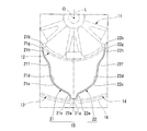
- FIG. 1 it is the schematic perspective view which decomposed
- the non-pneumatic tire 1 includes an attachment body 11 that is attached to an axle (not shown), an inner cylinder body 12 that is externally attached to the attachment body 11, and an outer cylinder body 13 that surrounds the inner cylinder body 12 from the outside in the tire radial direction.
- a plurality of ring members 14 are disposed along the tire circumferential direction between the inner cylindrical body 12 and the outer cylindrical body 13, and both the cylindrical bodies 12, 13 are connected to each other so as to be relatively elastically displaceable.
- a connecting member 15 and a tread member 16 disposed on the outer peripheral surface side of the outer cylindrical body 13 over the entire periphery thereof are provided.
- the attachment body 11, the inner cylinder body 12, the outer cylinder body 13, and the tread member 16 are each arranged coaxially with the common shaft.
- the common axis is referred to as an axis O
- a direction along the axis O is referred to as a tire width direction H
- a direction orthogonal to the axis O is referred to as a tire radial direction
- a direction around the axis O is referred to as a tire circumferential direction.
- the attachment body 11, the inner cylinder body 12, the outer cylinder body 13, and the tread member 16 are disposed such that the center portions in the tire width direction H are aligned with each other.
- the outer cylinder 13 is larger in size in the tire width direction H than the inner cylinder 12, that is, the width is larger.
- a plurality of protrusions 12a that protrude toward the inner side in the tire radial direction and extend over the entire length in the tire width direction H are disposed on the inner peripheral surface of the inner cylindrical body 12 at intervals in the tire circumferential direction. ing.
- the mounting body 11 includes a mounting cylinder portion 17 to which the front end portion of the axle is mounted, an outer ring portion 18 that surrounds the mounting cylinder portion 17 from the outside in the tire radial direction, and a mounting body 11 And a plurality of ribs 19 that connect the cylindrical portion 17 and the outer ring portion 18.
- the mounting cylinder portion 17, the outer ring portion 18, and the rib 19 are integrally formed of a metal material such as an aluminum alloy.
- the mounting cylinder portion 17 and the outer ring portion 18 are each formed in a cylindrical shape and arranged coaxially with the axis O.
- the plurality of ribs 19 are arranged point-symmetrically with respect to the axis O.
- a plurality of key groove portions 18a that are recessed toward the inside in the tire radial direction and that extend in the tire width direction H are formed on the outer peripheral surface of the outer ring portion 18 at intervals in the tire circumferential direction.
- the key groove portion 18 a is opened only on one side of both ends in the tire width direction H on the outer peripheral surface of the outer ring portion 18, and the other side is closed.
- the protrusions 12a of the inner cylinder 12 of the ring member 14 are fitted in these key groove portions 18a.
- the pair of side wall surfaces and the bottom wall surface facing each other in the tire circumferential direction form a right angle.
- a pair of side wall surfaces rising from the inner peripheral surface of the inner cylindrical body 12 and a top wall surface facing the inner side in the tire radial direction out of the outer surface of the protruding portion 12a form a right angle.
- the sizes of the protrusion 12a and the key groove 18a in the tire circumferential direction are equal to each other.
- a recess 18 b that is recessed toward the other side in the tire width direction H and into which the plate material 28 is fitted is located at a position corresponding to the key groove portion 18 a. Is formed.
- a through hole is formed in the plate material 28, and a female screw portion communicating with the through hole of the plate material 28 fitted in the recess 18b on a wall surface facing the one side in the tire width direction H among the wall surfaces defining the recess 18b. Is formed.
- a plurality of these internal thread portions and through holes are formed at intervals in the tire circumferential direction.
- the ring member 14 is bolted through the through hole of the plate member 28 fitted in the recess 18b in a state where the inner cylinder 12 is fitted on the attachment body 11 and the protrusion 12a is fitted in the key groove 18a. Is fixed to the attachment body 11 by screwing into the female thread portion.
- the protruding portion 12a is formed in the tire width direction H by the plate member 28 and the other wall surface facing the one side located at the other end in the tire width direction H among the wall surfaces defining the recess 18b. It is sandwiched.
- a plurality of hollow holes penetrating in the tire radial direction are arranged at intervals in the tire width direction H in a portion located between the key groove portions 18 a adjacent in the tire circumferential direction.
- a plurality of hole rows 18c are formed at intervals in the tire circumferential direction.
- the rib 19 is also formed with a hole 19a penetrating in the tire width direction H.
- the tread member 16 is formed in a cylindrical shape and integrally covers the outer peripheral surface side of the outer cylindrical body 13 of the ring member 14 over the entire area.
- the tread member 16 is made of, for example, vulcanized rubber obtained by vulcanizing natural rubber and / or a rubber composition, or a thermoplastic material.
- the thermoplastic material include a thermoplastic elastomer or a thermoplastic resin.
- the thermoplastic elastomer include amide-based thermoplastic elastomer (TPA), ester-based thermoplastic elastomer (TPC), olefin-based thermoplastic elastomer (TPO), styrene-based thermoplastic elastomer (TPS), and urethane as defined in JIS K6418.
- thermoplastic elastomer examples thereof include a thermoplastic elastomer (TPU), a crosslinked thermoplastic rubber (TPV), and other thermoplastic elastomers (TPZ).
- thermoplastic resin examples include urethane resin, olefin resin, vinyl chloride resin, and polyamide resin. From the viewpoint of wear resistance, it is preferable to form the tread member 16 from vulcanized rubber.
- the connecting member 15 connects the attachment body 11 and the outer cylinder body 13 so as to be relatively elastically displaceable.
- the connecting member 15 is connected to the attachment body 11 via the inner cylinder body 12.
- the connecting member 15 includes a first elastic connecting plate 21 and a second elastic connecting plate 22 that connect the inner cylinder 12 and the outer cylinder 13 in the ring member 14 to each other.
- a plurality of first elastic connecting plates 21 are arranged along a tire circumferential direction at predetermined positions along one tire width direction H, and the second elastic connecting plates 22 are arranged in the one tire width direction H.
- a plurality are provided along the tire circumferential direction so as to be arranged along the tire circumferential direction at other positions along the tire width direction H different from the predetermined positions along the tire. ing. That is, the plurality of first elastic connecting plates 21 are arranged at the same position in the tire width direction H along the tire circumferential direction, and the plurality of second elastic connecting plates 22 are separated from the first elastic connecting plate 21.
- a plurality of tires are arranged at predetermined positions along the tire width direction H that are separated in the tire width direction H along the tire circumferential direction.
- the first elastic connecting plate 21 and the second elastic connecting plate 22 are arranged with different predetermined positions along the tire width direction H, and the first elastic connecting plate 21 is on one side of the tire width direction H described above.
- the second elastic connecting plate 22 is located on the other side in the tire width direction H.
- the plurality of connecting members 15 are disposed between the inner cylinder 12 and the outer cylinder 13 of the ring member 14 at positions that are point-symmetric with respect to the axis O. All the connecting members 15 have the same shape and the same size. Furthermore, the width of the connecting member 15 is smaller than the width of the outer cylinder 13.
- the first elastic coupling plates 21 adjacent in the tire circumferential direction are not in contact with each other, and the second elastic coupling plates 22 adjacent in the tire circumferential direction are also in non-contact with each other. Further, the first elastic connecting plate 21 and the second elastic connecting plate 22 adjacent in the tire width direction H are also not in contact with each other.
- variety of each of the 1st elastic connection board 21 and the 2nd elastic connection board 22 is mutually equal. The thicknesses of the first elastic connecting plate 21 and the second elastic connecting plate 22 are also equal to each other.
- one end (outer end) 21a connected to the outer cylinder 13 is a tire than the other end (inner end) 21b connected to the inner cylinder 12.
- One end 22a of the second elastic connecting plate 22 connected to the outer cylinder 13 is located on one side in the circumferential direction, and the other end 22b connected to the inner cylinder 12 is the other in the tire circumferential direction.
- the respective one end portions 21 a and 22 a of the first elastic connecting plate 21 and the second elastic connecting plate 22 in one connecting member 15 are made to have different positions in the tire width direction H on the inner peripheral surface of the outer cylindrical body 13. And are connected to the same position in the tire circumferential direction.
- the other end portions 21b and 22b of the two elastic connecting plates 21 and 22 are in the tire radial direction as seen from the tire side when the tire 1 is viewed from the tire width direction H as shown in FIG.
- the imaginary line L that extends along the one end and passes through the one end portions 21a and 22a is arranged so as to be sandwiched between each other in the tire circumferential direction.
- each of the first elastic connecting plate 21 and the second elastic connecting plate 22 intermediate portions 21c and 22c positioned between the one end portions 21a and 22a and the other end portions 21b and 22b are arranged in the tire circumferential direction.
- a plurality of intermediate curved portions 21d to 21f and 22d to 22f that are curved are formed along the direction in which the elastic connecting plates 21 and 22 extend in a side view of the tire 1 when the tire 1 is viewed from the tire width direction H.
- the connecting plates 21 and 22 among the plurality of intermediate bending portions 21d to 21f and 22d to 22f, the bending directions of the intermediate bending portions 21d to 21f and 22d to 22f adjacent to each other in the extending direction are opposite to each other. It is facing.
- the plurality of intermediate curved portions 21d to 21f formed on the first elastic connecting plate 21 are a first intermediate curved portion 21d and a first intermediate curved portion 21d that are curved so as to protrude toward the other side in the tire circumferential direction. Between the first intermediate curved portion 21d and the other end portion 21b. The second intermediate curved portion 21e is curved between the first intermediate curved portion 21d and the other end portion 21b. A third intermediate curved portion 21f that is positioned and curved so as to project toward one side in the tire circumferential direction.
- the plurality of intermediate curved portions 22d to 22f formed on the second elastic connecting plate 22 are a first intermediate curved portion 22d and a first intermediate curved portion 22d that are curved so as to project toward one side in the tire circumferential direction. Between the first intermediate curved portion 22d and the other end portion 22b. The second intermediate curved portion 22e is located between the first intermediate curved portion 22a and the other end 22b. And a third intermediate curved portion 22f that is curved so as to project toward the other side in the tire circumferential direction.
- the first intermediate curved portions 21d and 22d are more than the second intermediate curved portions 21e and 22e and the third intermediate curved portions 21f and 22f.
- the visual radius of curvature is large.
- the first intermediate curved portions 21d and 22d are disposed at the center of the first elastic connecting plate 21 and the second elastic connecting plate 22 in the extending direction.
- the second intermediate curved portions 21e and 22e have a smaller radius of curvature in the tire side view than the third intermediate curved portions 21f and 22f.
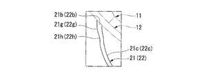
- the other end portions 21b, 22b of the both elastic connecting plates 21, 22 have end curved portions 21g, 21h, 22g, 22h that are curved in the tire circumferential direction, as described above in the tire side view.
- a plurality are formed along the extending direction.
- the bending directions of the end bending portions 21g, 21h, 22g, and 22h adjacent to each other in the extending direction are as follows. They are opposite to each other.
- the plurality of end curved portions 21g and 21h formed on the first elastic connecting plate 21 are curved so as to project toward the other side in the tire circumferential direction. It has an end curved portion 21g and a second end curved portion 21h curved so as to project toward one side in the tire circumferential direction.
- the first end curved portion 21g is located on the inner side in the tire radial direction and connected to the attachment body 11 via the inner cylinder 12, and the second end curved portion 21h is located on the outer side in the tire radial direction.
- the first elastic connecting plate 21 is connected to the intermediate portion 21c. As shown in FIG.
- the plurality of end curved portions 22g and 22h formed on the second elastic connecting plate 22 are curved so as to project toward one side in the tire circumferential direction. 22g and the 2nd end part curved part 22h curved so that it may protrude toward the other side of a tire peripheral direction.
- the second end curved portion 22g is located on the inner side in the tire radial direction and connected to the attachment body 11 via the inner cylindrical body 12, and the second end curved portion 22h is located on the outer side in the tire radial direction.
- the second elastic connecting plate 22 is connected to the intermediate portion 22c.
- first end curved portions 21g and 22g and the second end curved portions 21h and 22h have the same radius of curvature as viewed from the side of the tire for both the elastic connecting plates 21 and 22. ing. Further, the end curved portions 21g, 22g, 21h and 22h have a smaller radius of curvature in the tire side view than the intermediate curved portions 21d to 21f and 22d to 22f.
- the lengths of the two elastic connecting plates 21 and 22 are equal to each other, and the other end portions 21b and 22b of the two elastic connecting plates 21 and 22 are, as shown in FIG.
- the same angle for example, 20 ° or more
- the same angle on one side and the other side in the tire circumferential direction around the axis O from the position facing the one end portions 21a, 22a in the tire radial direction on the outer peripheral surface of the inner cylindrical body 12 135 [deg.] Or less).
- first intermediate bending portions 21d and 22d, the second intermediate bending portions 21e and 22e, and the third intermediate bending portions 21f and 22f of the first elastic connecting plate 21 and the second elastic connecting plate 22, respectively The direction of protrusion in the tire circumferential direction is opposite and the size is the same. Further, the first end curved portions 21g and 22g of the first elastic connecting plate 21 and the second elastic connecting plate 22 and the second end curved portions 21h and 22h are projected in the tire circumferential direction. Is the opposite and the size is the same.
- each connecting member 15 in the tire side view is line-symmetric with respect to the virtual line L as shown in FIG.
- the elastic connecting plates 21 and 22 gradually extend away from the virtual line L in the tire circumferential direction as they go from the one end 21a and 22a to the other end 21b and 22b, respectively.
- the thickness of one end side portion extending from the central portion in the extending direction to the one end portions 21a and 22a is equal to the other end side extending from the central portion to the other end portions 21b and 22b. It may be larger than the thickness of the portion.
- the strength of the one end side portion where a large load is easily applied to the first and second elastic connecting plates 21 and 22 is increased. Can be increased. Further, at this time, the one end side portion and the other end side portion may be smoothly connected without a step.
- the ring member 14 and the plurality of connecting members 15 are integrally formed. Further, in the present embodiment, as shown in FIG. 1, the ring member 14 is divided into one side split ring member 23 located on one side in the tire width direction H and the other side division located on the other side in the tire width direction H. It is divided into a ring member 24. In the illustrated example, the ring member 14 is divided at the center in the tire width direction H.
- the one-side split ring member 23 is formed integrally with the first elastic connecting plate 21, and the other-side split ring member 24 is formed integrally with the second elastic connecting plate 22. Further, in the present embodiment, the one-side split ring member 23 and the first elastic connecting plate 21, and the other-side split ring member 24 and the second elastic connecting plate 22 are integrally formed by casting or injection molding, respectively.
- a structure in which the one-side split ring member 23 and the first elastic connecting plate 21 are integrally formed is referred to as a first split case body 31, and the other-side split ring member 24 and the second elastic connecting plate 22 are integrally formed. This is referred to as a second divided case body 32.
- the injection molding may be a general method in which the entire first and second divided case bodies 31 and 32 are simultaneously molded, or in each of the first and second divided case bodies 31 and 32.
- one side or the other side split ring members 23 and 24 and one of the first and second elastic connecting plates 21 and 22 may be insert moldings, and the other may be injection molding, or so-called two-color molding, etc. It may be.
- the one side and the other side split ring members 23 and 24 and the first and second elastic connecting plates 21 and 22 are formed of different materials. Alternatively, the same material may be used.
- this material examples include a metal material and a resin material, but a resin material, particularly a thermoplastic resin is preferable from the viewpoint of weight reduction.
- a plurality of protrusions 12a formed on the inner cylindrical body 12 may be used as gate portions.
- the inner cylindrical body 12 has a width smaller than that of the outer cylindrical body 13, and each of the first elastic connecting plate 21 and the second elastic connecting plate 22. It is equivalent to the width.
- edges in the tire width direction H of the outer cylindrical body 13 of the one-side split ring member 23 and the outer cylindrical body 13 of the other-side split ring member 24 are connected by, for example, welding, fusion, or adhesion. Yes. Of these, in the case of welding, for example, hot plate welding or the like may be employed. Further, the edges in the tire width direction H of the inner cylinder 12 of the one-side split ring member 23 and the inner cylinder 12 of the other-side split ring member 24 are separated in the tire width direction H. Thereby, it is prevented that the burr
- first divided case body 31 and the second divided case body 32 have the same shape and the same size as each other as shown in FIG. 3 in a state before the connection of the 31 and 32 as described above. .
- each connecting member 15 in the tire circumferential direction of each of the first divided case body 31 and the second divided case body 32 is line-symmetric as described above in the tire side view.
- the outer casings 13 of the first split case body 31 and the second split case body 32 are in a state in which the directions of the tire width direction H of the split case bodies 31 and 32 are opposite to each other.
- the non-pneumatic tire 1 can be obtained by connecting the end edges in the tire width direction H while abutting each other.
- the end curved portions 21g, 21h, 22g, and 22h are formed on the other end portions 21b and 22b of the elastic coupling plates 21 and 22, respectively. Therefore, when an external force is applied to the non-pneumatic tire 1 and the attachment body 11 and the outer cylinder body 13 are relatively displaced, the other end portions 21b of the respective elastic coupling plates 21 and 22 according to the displacement. 22b, the plurality of end curved portions 21g, 21h, 22g, and 22h are elastically deformed.
- both elastic connecting plates 21 and 22 gradually extend away from the imaginary line L in the tire circumferential direction as they go from the one end 21a and 22a to the other end 21b and 22b, this non-pneumatic When an external force is applied to the tire 1 and the attachment body 11 and the outer cylinder body 13 are relatively displaced, the elastic connecting plates 21 and 22 can be suitably elastically deformed as a whole. Thereby, the external force applied to the non-pneumatic tire 1 can be easily dispersed effectively within the elastic connecting plates 21 and 22.
- first and second divided case bodies 31 and 32 are provided, for example, both end portions 21a, 22a, 21b, and 22b of the connecting member 15, the inner cylinder body 12 and the outer cylinder body 13 are connected to the fastening member.
- the weight can be reduced as compared with the case of connecting with the like.
- a plurality of first elastic connecting plates 21 are arranged along the tire circumferential direction at a position in one tire width direction H
- the second elastic connecting plates 22 are arranged around the tire circumference at other tire width direction H positions. Since a plurality of the members are arranged along the direction, it is possible to prevent the adjacent connecting members 15 from interfering with each other in the tire circumferential direction, and it is possible to suppress the restriction on the number of the arranged members.
- one end 21 a connected to the outer cylinder 13 is located on one side in the tire circumferential direction with respect to the other end 21 b connected to the inner cylinder 12, and the second Of the elastic connecting plate 22, one end 22 a connected to the outer cylinder 13 is located on the other side in the tire circumferential direction with respect to the other end 22 b connected to the inner cylinder 12.
- the first elastic connecting plate 21 and the second elastic connecting plate 22 can be easily elastically deformed, and the non-pneumatic tire 1 has good flexibility. Secure ride comfort.
- the first elastic connecting plate 21 and the second elastic connecting plate 22 are arranged between the outer cylindrical body 13 and the inner cylindrical body 12.
- the ring member 14 and the connecting member 15 are formed, only one of a plurality extending in a certain direction is disposed and the other extending in the other direction is not disposed in a side view of the tire.
- the entire ring member 14 and the connecting member 15 are integrally formed to form a case structure with a complicated structure. Compared to the case, the non-pneumatic tire 1 can be formed easily and reliably.
- the connecting member 15 is formed symmetrically with respect to the virtual line L in the tire side view, the spring constant along one side in the tire circumferential direction and the other side of the non-pneumatic tire 1 are along. It becomes possible to suppress a difference between the spring constant and good maneuverability.
- the bending direction of the intermediate bending portions 21d to 21f in the first elastic connecting plate 21 and the bending direction of the intermediate bending portions 22d to 22f in the second elastic connecting plate 22 are not limited to the above-described embodiment, and may be changed as appropriate. .
- the structure provided with the 1st elastic connection board 21 and the 2nd elastic connection board 22 each as the connection member 15 was shown, it replaced with this and the 1st connection member 15 is 1st.
- a configuration may be adopted in which a plurality of elastic connecting plates 21 and a plurality of second elastic connecting plates 22 are provided in different positions in the tire width direction H.
- a plurality of connecting members 15 may be provided along the tire width direction H between the inner cylinder 12 and the outer cylinder 13.
- the other end portions 21b and 22b of the first elastic connecting plate 21 and the second elastic connecting plate 22 are, for example, the axial line O in the tire radial direction on the outer peripheral surface of the inner cylinder 12 instead of the embodiment. It may be connected to each position opposite to each other, or on the outer peripheral surface of the inner cylindrical body 12, tires are connected to the respective one end portions 21a, 22a of the first elastic connecting plate 21 and the second elastic connecting plate 22. You may connect with the position etc. which oppose in radial direction. Further, instead of the above-described embodiment, the one end portions 21a and 22a of both the connecting plates 21 and 22 may be connected to the inner peripheral surface of the outer cylindrical body 13 at different positions in the tire circumferential direction.
- first and second divided case bodies 31 and 32 are not limited to the above embodiment, and may be formed by, for example, cutting.
- both the elastic connection plates 21 and 22 are extended so that it may be spaced apart from the said virtual line L in the tire circumferential direction gradually toward the other end parts 21b and 22b from the one end parts 21a and 22a, respectively. However, it is not limited to this.
- the ring member 14 and the plurality of connecting members 15 may not be integrally formed. Furthermore, the ring member 14 and the connecting member 15 are not limited to those shown in the embodiment.
- the inner cylindrical body may not be provided, and the outer cylindrical body and the attachment body may be directly connected via a connecting member so as to be relatively elastically displaceable.
- the strength of the connecting member of the non-pneumatic tire is improved.
Abstract
This non-pneumatic tire is provided with: an attachment body (11) attached to an axle; an outer tube body (13) that encircles the attachment body (11) from the outside in the radial direction of the tire; and a linking member (15) that displaceably links the attachment body (11) and the outer tube body (13). The linking member (15) is provided with elastic linking plates (21, 22) of which both ends (21a, 21b, 22a, 22b) are respectively linked to the attachment body (11) and the outer tube body (13). Of the elastic linking plates (21, 22), at the inner ends (21b, 22b) linked to the attachment body (11) are formed a plurality of end curved surface sections (21g, 21h, 22g, 22h) that are curved in the peripheral direction of the tire and that extend in the direction of extension of the elastic linking plates (21, 22) in a lateral view of the tire when the tire is seen from the direction of tire width. Of the end curved surface sections (21g, 21h, 22g, 22h), the direction of curvature of each adjacent end curved surface section (21g, 21h, 22g, 22h) alternates.
Description
本発明は、使用に際し内部に加圧空気の充填が不要な非空気入りタイヤに関する。
本願は、2012年11月5日に、日本に出願された特願2012-243826号に基づき優先権を主張し、その内容をここに援用する。 The present invention relates to a non-pneumatic tire that does not need to be filled with pressurized air when used.
This application claims priority based on Japanese Patent Application No. 2012-243826 for which it applied to Japan on November 5, 2012, and uses the content here.
内部に加圧空気が充填されて用いられる従来の空気入りタイヤでは、パンクの発生は構造上不可避的な問題となっている。このような問題を解決するために近年では、例えば下記特許文献1に示されるような、車軸に取り付けられる取り付け体と、取り付け体をタイヤ径方向の外側から囲む外筒体と、取り付け体と外筒体とを変位自在に連結する連結部材と、を備える非空気入りタイヤが提案されている。前記連結部材は、両端部が取り付け体および外筒体にそれぞれ連結された弾性連結板を備えている。
In a conventional pneumatic tire that is filled with pressurized air, the occurrence of puncture is an unavoidable problem due to its structure. In order to solve such problems, in recent years, for example, as shown in Patent Document 1 below, an attachment body attached to an axle, an outer cylinder surrounding the attachment body from the outside in the tire radial direction, an attachment body, and an outer There has been proposed a non-pneumatic tire including a connecting member that displaceably connects a cylindrical body. The connecting member includes an elastic connecting plate having both ends connected to an attachment body and an outer cylinder body, respectively.
しかしながら、前記従来の非空気入りタイヤでは、連結部材の強度を向上させることについて改善の余地がある。
However, the conventional non-pneumatic tire has room for improvement in improving the strength of the connecting member.
本発明は、前述した事情に鑑みてなされたものであって、連結部材の強度を向上させることができる非空気入りタイヤを提供することを目的とする。
The present invention has been made in view of the above-described circumstances, and an object thereof is to provide a non-pneumatic tire that can improve the strength of a connecting member.
本発明に係る、第1の態様の発明によれば、弾性連結板の内端部に、端部湾曲部が形成されているので、この非空気入りタイヤに外力が加えられて取り付け体と外筒体とが相対的に変位するときに、この変位に応じてそれぞれの弾性連結板の内端部で複数の端部湾曲部が弾性変形することとなる。したがって、このときに弾性連結板の内端部に集中して作用しようとする応力を分散させ易くすることが可能になり、弾性連結板内で局所的に大きな負荷が加わる部分が生ずるのを抑制できる。これにより、連結部材の強度を向上させることができるとともに、衝撃力を吸収させ易くして良好な乗り心地性を備えさせることができる。
According to the first aspect of the present invention, since the end curved portion is formed at the inner end portion of the elastic connecting plate, an external force is applied to the non-pneumatic tire and the attachment body and the outer When the cylinder body is relatively displaced, the plurality of end curved portions are elastically deformed at the inner end portions of the respective elastic connecting plates in accordance with the displacement. Therefore, it is possible to easily disperse the stress that tends to concentrate on the inner end portion of the elastic connecting plate at this time, and suppress the occurrence of a portion where a large load is locally applied in the elastic connecting plate. it can. Thereby, while being able to improve the intensity | strength of a connection member, it can make it easy to absorb impact force and can be equipped with favorable riding comfort.
本発明に係る、第2の態様の発明によれば、上記第1の態様において、両弾性連結板はそれぞれ、外端部から内端部に向かうに従い漸次、仮想線からタイヤ周方向に離間するように延びているので、この非空気入りタイヤに外力が加えられて取り付け体と外筒体とが相対的に変位するときに、弾性連結板を全体で好適に弾性変形させることができる。これにより、非空気入りタイヤに加えられた外力を、各弾性連結板内で効果的に分散させ易くすることができる。
According to the second aspect of the present invention, in the first aspect, both elastic connecting plates are gradually separated from the imaginary line in the tire circumferential direction as they go from the outer end to the inner end. Therefore, when an external force is applied to the non-pneumatic tire and the attachment body and the outer cylinder body are relatively displaced, the elastic connecting plate can be suitably elastically deformed as a whole. Thereby, the external force applied to the non-pneumatic tire can be easily dispersed effectively within each elastic connecting plate.
本発明に係る非空気入りタイヤによれば、連結部材の強度を向上させることができる。
According to the non-pneumatic tire according to the present invention, the strength of the connecting member can be improved.
以下、本発明に係る非空気入りタイヤの一実施形態を図1から図5を参照しながら説明する。
この非空気入りタイヤ1は、図示されない車軸に取り付けられる取り付け体11と、取り付け体11に外装される内筒体12、および内筒体12をタイヤ径方向の外側から囲む外筒体13を備えるリング部材14と、内筒体12と外筒体13との間にタイヤ周方向に沿って複数配設されるとともに、これらの両筒体12、13同士を相対的に弾性変位自在に連結する連結部材15と、外筒体13の外周面側にその全周にわたって配設されたトレッド部材16と、を備えている。 Hereinafter, an embodiment of a non-pneumatic tire according to the present invention will be described with reference to FIGS. 1 to 5.
Thenon-pneumatic tire 1 includes an attachment body 11 that is attached to an axle (not shown), an inner cylinder body 12 that is externally attached to the attachment body 11, and an outer cylinder body 13 that surrounds the inner cylinder body 12 from the outside in the tire radial direction. A plurality of ring members 14 are disposed along the tire circumferential direction between the inner cylindrical body 12 and the outer cylindrical body 13, and both the cylindrical bodies 12, 13 are connected to each other so as to be relatively elastically displaceable. A connecting member 15 and a tread member 16 disposed on the outer peripheral surface side of the outer cylindrical body 13 over the entire periphery thereof are provided.
この非空気入りタイヤ1は、図示されない車軸に取り付けられる取り付け体11と、取り付け体11に外装される内筒体12、および内筒体12をタイヤ径方向の外側から囲む外筒体13を備えるリング部材14と、内筒体12と外筒体13との間にタイヤ周方向に沿って複数配設されるとともに、これらの両筒体12、13同士を相対的に弾性変位自在に連結する連結部材15と、外筒体13の外周面側にその全周にわたって配設されたトレッド部材16と、を備えている。 Hereinafter, an embodiment of a non-pneumatic tire according to the present invention will be described with reference to FIGS. 1 to 5.
The
ここで、取り付け体11、内筒体12、外筒体13、およびトレッド部材16はそれぞれ、共通軸と同軸に配設されている。以下、この共通軸を軸線Oといい、この軸線Oに沿う方向をタイヤ幅方向Hといい、軸線Oに直交する方向をタイヤ径方向といい、軸線O回りに周回する方向をタイヤ周方向という。なお、取り付け体11、内筒体12、外筒体13、およびトレッド部材16は、タイヤ幅方向Hの中央部が互いに一致させられて配設されている。
Here, the attachment body 11, the inner cylinder body 12, the outer cylinder body 13, and the tread member 16 are each arranged coaxially with the common shaft. Hereinafter, the common axis is referred to as an axis O, a direction along the axis O is referred to as a tire width direction H, a direction orthogonal to the axis O is referred to as a tire radial direction, and a direction around the axis O is referred to as a tire circumferential direction. . In addition, the attachment body 11, the inner cylinder body 12, the outer cylinder body 13, and the tread member 16 are disposed such that the center portions in the tire width direction H are aligned with each other.
リング部材14のうち、外筒体13は内筒体12よりもタイヤ幅方向Hの大きさ、つまり幅が大きくなっている。また、内筒体12の内周面には、タイヤ径方向の内側に向けて突出するとともにタイヤ幅方向Hの全長にわたって延びる突条部12aが、タイヤ周方向に間隔をあけて複数配設されている。
Among the ring members 14, the outer cylinder 13 is larger in size in the tire width direction H than the inner cylinder 12, that is, the width is larger. A plurality of protrusions 12a that protrude toward the inner side in the tire radial direction and extend over the entire length in the tire width direction H are disposed on the inner peripheral surface of the inner cylindrical body 12 at intervals in the tire circumferential direction. ing.
取り付け体11は、図1および図2に示されるように、前記車軸の先端部が装着される装着筒部17と、装着筒部17をタイヤ径方向の外側から囲む外リング部18と、装着筒部17と外リング部18とを連結する複数のリブ19と、を備えている。
装着筒部17、外リング部18、およびリブ19は例えばアルミニウム合金等の金属材料で一体に形成されている。装着筒部17および外リング部18はそれぞれ、円筒状に形成され前記軸線Oと同軸に配設されている。複数のリブ19は、前記軸線Oを基準とする点対称に配置されている。 As shown in FIGS. 1 and 2, themounting body 11 includes a mounting cylinder portion 17 to which the front end portion of the axle is mounted, an outer ring portion 18 that surrounds the mounting cylinder portion 17 from the outside in the tire radial direction, and a mounting body 11 And a plurality of ribs 19 that connect the cylindrical portion 17 and the outer ring portion 18.
Themounting cylinder portion 17, the outer ring portion 18, and the rib 19 are integrally formed of a metal material such as an aluminum alloy. The mounting cylinder portion 17 and the outer ring portion 18 are each formed in a cylindrical shape and arranged coaxially with the axis O. The plurality of ribs 19 are arranged point-symmetrically with respect to the axis O.
装着筒部17、外リング部18、およびリブ19は例えばアルミニウム合金等の金属材料で一体に形成されている。装着筒部17および外リング部18はそれぞれ、円筒状に形成され前記軸線Oと同軸に配設されている。複数のリブ19は、前記軸線Oを基準とする点対称に配置されている。 As shown in FIGS. 1 and 2, the
The
外リング部18の外周面には、タイヤ径方向の内側に向けて窪み、かつタイヤ幅方向Hに延びるキー溝部18aがタイヤ周方向に間隔をあけて複数形成されている。キー溝部18aは、外リング部18の外周面において、タイヤ幅方向Hの両端のうちの一方側にのみ開口し他方側は閉じている。これらのキー溝部18aに、リング部材14における内筒体12の突条部12aがそれぞれ嵌合している。
なお、キー溝部18aを画成する壁面のうち、タイヤ周方向で互いに対向する一対の側壁面と底壁面とは直角をなしている。また、突条部12aの外表面のうち、内筒体12の内周面から立ち上がる一対の側壁面と、タイヤ径方向の内側を向く頂壁面と、は直角をなしている。突条部12aおよびキー溝部18aのタイヤ周方向の大きさは互いに同等になっている。 A plurality ofkey groove portions 18a that are recessed toward the inside in the tire radial direction and that extend in the tire width direction H are formed on the outer peripheral surface of the outer ring portion 18 at intervals in the tire circumferential direction. The key groove portion 18 a is opened only on one side of both ends in the tire width direction H on the outer peripheral surface of the outer ring portion 18, and the other side is closed. The protrusions 12a of the inner cylinder 12 of the ring member 14 are fitted in these key groove portions 18a.
Of the wall surfaces defining thekey groove portion 18a, the pair of side wall surfaces and the bottom wall surface facing each other in the tire circumferential direction form a right angle. In addition, a pair of side wall surfaces rising from the inner peripheral surface of the inner cylindrical body 12 and a top wall surface facing the inner side in the tire radial direction out of the outer surface of the protruding portion 12a form a right angle. The sizes of the protrusion 12a and the key groove 18a in the tire circumferential direction are equal to each other.
なお、キー溝部18aを画成する壁面のうち、タイヤ周方向で互いに対向する一対の側壁面と底壁面とは直角をなしている。また、突条部12aの外表面のうち、内筒体12の内周面から立ち上がる一対の側壁面と、タイヤ径方向の内側を向く頂壁面と、は直角をなしている。突条部12aおよびキー溝部18aのタイヤ周方向の大きさは互いに同等になっている。 A plurality of
Of the wall surfaces defining the
ここで、外リング部18におけるタイヤ幅方向Hの一方側の端縁において、キー溝部18aと対応する位置に、タイヤ幅方向Hの他方側に向けて窪み、かつ板材28が嵌め込まれる凹部18bが形成されている。板材28には貫通孔が形成されていて、凹部18bを画成する壁面のうち、タイヤ幅方向Hの一方側を向く壁面に、凹部18bに嵌め込まれた板材28の貫通孔に連通する雌ねじ部が形成されている。なお、これらの雌ねじ部および貫通孔はタイヤ周方向に間隔をあけて複数形成されている。
Here, at the edge of one side in the tire width direction H in the outer ring portion 18, a recess 18 b that is recessed toward the other side in the tire width direction H and into which the plate material 28 is fitted is located at a position corresponding to the key groove portion 18 a. Is formed. A through hole is formed in the plate material 28, and a female screw portion communicating with the through hole of the plate material 28 fitted in the recess 18b on a wall surface facing the one side in the tire width direction H among the wall surfaces defining the recess 18b. Is formed. A plurality of these internal thread portions and through holes are formed at intervals in the tire circumferential direction.
そして、リング部材14は、内筒体12が取り付け体11に外嵌され、かつ突条部12aがキー溝部18aに嵌合された状態で、凹部18bに嵌め込んだ板材28の貫通孔を通してボルトを雌ねじ部にねじ込むことにより、取り付け体11に固定されている。この状態において、突条部12aは、板材28と、凹部18bを画成する壁面のうち、タイヤ幅方向Hの他端に位置して一方側を向く他端壁面と、によりタイヤ幅方向Hに挟み込まれている。
なお、外リング部18において、タイヤ周方向で隣り合うキー溝部18a同士の間に位置する部分には、タイヤ径方向に貫通する肉抜き孔がタイヤ幅方向Hに間隔をあけて複数配置されてなる孔列18cが、タイヤ周方向に間隔をあけて複数形成されている。また、リブ19にも、タイヤ幅方向Hに貫通する肉抜き孔19aが形成されている。 Then, thering member 14 is bolted through the through hole of the plate member 28 fitted in the recess 18b in a state where the inner cylinder 12 is fitted on the attachment body 11 and the protrusion 12a is fitted in the key groove 18a. Is fixed to the attachment body 11 by screwing into the female thread portion. In this state, the protruding portion 12a is formed in the tire width direction H by the plate member 28 and the other wall surface facing the one side located at the other end in the tire width direction H among the wall surfaces defining the recess 18b. It is sandwiched.
In theouter ring portion 18, a plurality of hollow holes penetrating in the tire radial direction are arranged at intervals in the tire width direction H in a portion located between the key groove portions 18 a adjacent in the tire circumferential direction. A plurality of hole rows 18c are formed at intervals in the tire circumferential direction. The rib 19 is also formed with a hole 19a penetrating in the tire width direction H.
なお、外リング部18において、タイヤ周方向で隣り合うキー溝部18a同士の間に位置する部分には、タイヤ径方向に貫通する肉抜き孔がタイヤ幅方向Hに間隔をあけて複数配置されてなる孔列18cが、タイヤ周方向に間隔をあけて複数形成されている。また、リブ19にも、タイヤ幅方向Hに貫通する肉抜き孔19aが形成されている。 Then, the
In the
トレッド部材16は円筒状に形成され、リング部材14の外筒体13の外周面側を全域にわたって一体に覆っている。トレッド部材16は、例えば、天然ゴムまたは/およびゴム組成物が加硫された加硫ゴム、あるいは熱可塑性材料等で形成されている。熱可塑性材料として、例えば熱可塑性エラストマー若しくは熱可塑性樹脂等が挙げられる。熱可塑性エラストマーとしては、例えばJIS K6418に規定されるアミド系熱可塑性エラストマー(TPA)、エステル系熱可塑性エラストマー(TPC)、オレフィン系熱可塑性エラストマー(TPO)、スチレン系熱可塑性エラストマー(TPS)、ウレタン系熱可塑性エラストマー(TPU)、熱可塑性ゴム架橋体(TPV)、若しくはその他の熱可塑性エラストマー(TPZ)等が挙げられる。熱可塑性樹脂としては、例えばウレタン樹脂、オレフィン樹脂、塩化ビニル樹脂、若しくはポリアミド樹脂等が挙げられる。なお、耐摩耗性の観点ではトレッド部材16を加硫ゴムで形成するのが好ましい。
The tread member 16 is formed in a cylindrical shape and integrally covers the outer peripheral surface side of the outer cylindrical body 13 of the ring member 14 over the entire area. The tread member 16 is made of, for example, vulcanized rubber obtained by vulcanizing natural rubber and / or a rubber composition, or a thermoplastic material. Examples of the thermoplastic material include a thermoplastic elastomer or a thermoplastic resin. Examples of the thermoplastic elastomer include amide-based thermoplastic elastomer (TPA), ester-based thermoplastic elastomer (TPC), olefin-based thermoplastic elastomer (TPO), styrene-based thermoplastic elastomer (TPS), and urethane as defined in JIS K6418. Examples thereof include a thermoplastic elastomer (TPU), a crosslinked thermoplastic rubber (TPV), and other thermoplastic elastomers (TPZ). Examples of the thermoplastic resin include urethane resin, olefin resin, vinyl chloride resin, and polyamide resin. From the viewpoint of wear resistance, it is preferable to form the tread member 16 from vulcanized rubber.
連結部材15は、取り付け体11と外筒体13とを相対的に弾性変位自在に連結する。
連結部材15は、取り付け体11に内筒体12を介して連結されている。連結部材15は、リング部材14における内筒体12と外筒体13とを互いに連結する第1弾性連結板21および第2弾性連結板22を備えている。
連結部材15は、第1弾性連結板21が一のタイヤ幅方向Hに沿った所定の位置にタイヤ周方向に沿って複数配置され、かつ第2弾性連結板22が前記一のタイヤ幅方向Hに沿った所定の位置とは異なるタイヤ幅方向Hに沿った他の位置にタイヤ周方向に沿って複数配置されるように、タイヤ周方向に沿って複数(図示の例では60個)設けられている。
すなわち、複数の第1弾性連結板21は、タイヤ幅方向Hにおける同一の位置にタイヤ周方向に沿って複数配置されるとともに、複数の第2弾性連結板22は、第1弾性連結板21からタイヤ幅方向Hに離れた同一のタイヤ幅方向Hに沿った所定の位置にタイヤ周方向に沿って複数配置されている。第1弾性連結板21および第2弾性連結板22は、タイヤ幅方向Hに沿った所定の位置を互いに異ならせて配置され、第1弾性連結板21は、前述したタイヤ幅方向Hの一方側に位置し、第2弾性連結板22は、タイヤ幅方向Hの他方側に位置している。 The connectingmember 15 connects the attachment body 11 and the outer cylinder body 13 so as to be relatively elastically displaceable.
The connectingmember 15 is connected to the attachment body 11 via the inner cylinder body 12. The connecting member 15 includes a first elastic connecting plate 21 and a second elastic connecting plate 22 that connect the inner cylinder 12 and the outer cylinder 13 in the ring member 14 to each other.
In the connectingmember 15, a plurality of first elastic connecting plates 21 are arranged along a tire circumferential direction at predetermined positions along one tire width direction H, and the second elastic connecting plates 22 are arranged in the one tire width direction H. A plurality (60 in the illustrated example) are provided along the tire circumferential direction so as to be arranged along the tire circumferential direction at other positions along the tire width direction H different from the predetermined positions along the tire. ing.
That is, the plurality of first elastic connectingplates 21 are arranged at the same position in the tire width direction H along the tire circumferential direction, and the plurality of second elastic connecting plates 22 are separated from the first elastic connecting plate 21. A plurality of tires are arranged at predetermined positions along the tire width direction H that are separated in the tire width direction H along the tire circumferential direction. The first elastic connecting plate 21 and the second elastic connecting plate 22 are arranged with different predetermined positions along the tire width direction H, and the first elastic connecting plate 21 is on one side of the tire width direction H described above. The second elastic connecting plate 22 is located on the other side in the tire width direction H.
連結部材15は、取り付け体11に内筒体12を介して連結されている。連結部材15は、リング部材14における内筒体12と外筒体13とを互いに連結する第1弾性連結板21および第2弾性連結板22を備えている。
連結部材15は、第1弾性連結板21が一のタイヤ幅方向Hに沿った所定の位置にタイヤ周方向に沿って複数配置され、かつ第2弾性連結板22が前記一のタイヤ幅方向Hに沿った所定の位置とは異なるタイヤ幅方向Hに沿った他の位置にタイヤ周方向に沿って複数配置されるように、タイヤ周方向に沿って複数(図示の例では60個)設けられている。
すなわち、複数の第1弾性連結板21は、タイヤ幅方向Hにおける同一の位置にタイヤ周方向に沿って複数配置されるとともに、複数の第2弾性連結板22は、第1弾性連結板21からタイヤ幅方向Hに離れた同一のタイヤ幅方向Hに沿った所定の位置にタイヤ周方向に沿って複数配置されている。第1弾性連結板21および第2弾性連結板22は、タイヤ幅方向Hに沿った所定の位置を互いに異ならせて配置され、第1弾性連結板21は、前述したタイヤ幅方向Hの一方側に位置し、第2弾性連結板22は、タイヤ幅方向Hの他方側に位置している。 The connecting
The connecting
In the connecting
That is, the plurality of first elastic connecting
なお、複数の連結部材15は、リング部材14における内筒体12と外筒体13との間において、前記軸線Oを基準に互いに点対称となる位置にそれぞれ配置されている。また、全ての連結部材15は互いに同一形状かつ同一サイズとなっている。さらに、連結部材15の幅は外筒体13の幅より小さくなっている。
そして、タイヤ周方向で隣り合う第1弾性連結板21同士は互いに非接触とされ、タイヤ周方向で隣り合う第2弾性連結板22同士も互いに非接触となっている。さらに、タイヤ幅方向Hで隣り合う第1弾性連結板21および第2弾性連結板22同士も互いに非接触となっている。
なお、第1弾性連結板21および第2弾性連結板22それぞれの幅は互いに同等になっている。また、第1弾性連結板21および第2弾性連結板22それぞれの厚さも互いに同等になっている。 The plurality of connectingmembers 15 are disposed between the inner cylinder 12 and the outer cylinder 13 of the ring member 14 at positions that are point-symmetric with respect to the axis O. All the connecting members 15 have the same shape and the same size. Furthermore, the width of the connecting member 15 is smaller than the width of the outer cylinder 13.
The firstelastic coupling plates 21 adjacent in the tire circumferential direction are not in contact with each other, and the second elastic coupling plates 22 adjacent in the tire circumferential direction are also in non-contact with each other. Further, the first elastic connecting plate 21 and the second elastic connecting plate 22 adjacent in the tire width direction H are also not in contact with each other.
In addition, the width | variety of each of the 1stelastic connection board 21 and the 2nd elastic connection board 22 is mutually equal. The thicknesses of the first elastic connecting plate 21 and the second elastic connecting plate 22 are also equal to each other.
そして、タイヤ周方向で隣り合う第1弾性連結板21同士は互いに非接触とされ、タイヤ周方向で隣り合う第2弾性連結板22同士も互いに非接触となっている。さらに、タイヤ幅方向Hで隣り合う第1弾性連結板21および第2弾性連結板22同士も互いに非接触となっている。
なお、第1弾性連結板21および第2弾性連結板22それぞれの幅は互いに同等になっている。また、第1弾性連結板21および第2弾性連結板22それぞれの厚さも互いに同等になっている。 The plurality of connecting
The first
In addition, the width | variety of each of the 1st
ここで、第1弾性連結板21のうち、外筒体13に連結された一端部(外端部)21aは、内筒体12に連結された他端部(内端部)21bよりもタイヤ周方向の一方側に位置し、第2弾性連結板22のうち、外筒体13に連結された一端部22aは、内筒体12に連結された他端部22bよりもタイヤ周方向の他方側に位置している。
また、1つの連結部材15における第1弾性連結板21および第2弾性連結板22の各一端部21a、22aは、外筒体13の内周面において、タイヤ幅方向Hの位置を互いに異ならせて、タイヤ周方向における同一の位置に連結されている。
これにより、両弾性連結板21、22同士のうち、他端部21b、22b同士は、図4に示されるように、このタイヤ1をタイヤ幅方向Hから見たタイヤ側面視で、タイヤ径方向に沿って延びかつ各一端部21a、22aを通る仮想線Lを、互いの間にタイヤ周方向に挟むように配置されることとなる。 Here, in the first elastic connectingplate 21, one end (outer end) 21a connected to the outer cylinder 13 is a tire than the other end (inner end) 21b connected to the inner cylinder 12. One end 22a of the second elastic connecting plate 22 connected to the outer cylinder 13 is located on one side in the circumferential direction, and the other end 22b connected to the inner cylinder 12 is the other in the tire circumferential direction. Located on the side.
Further, the respective one end portions 21 a and 22 a of the first elastic connecting plate 21 and the second elastic connecting plate 22 in one connecting member 15 are made to have different positions in the tire width direction H on the inner peripheral surface of the outer cylindrical body 13. And are connected to the same position in the tire circumferential direction.
As a result, the other end portions 21b and 22b of the two elastic connecting plates 21 and 22 are in the tire radial direction as seen from the tire side when the tire 1 is viewed from the tire width direction H as shown in FIG. The imaginary line L that extends along the one end and passes through the one end portions 21a and 22a is arranged so as to be sandwiched between each other in the tire circumferential direction.
また、1つの連結部材15における第1弾性連結板21および第2弾性連結板22の各一端部21a、22aは、外筒体13の内周面において、タイヤ幅方向Hの位置を互いに異ならせて、タイヤ周方向における同一の位置に連結されている。
これにより、両弾性連結板21、22同士のうち、他端部21b、22b同士は、図4に示されるように、このタイヤ1をタイヤ幅方向Hから見たタイヤ側面視で、タイヤ径方向に沿って延びかつ各一端部21a、22aを通る仮想線Lを、互いの間にタイヤ周方向に挟むように配置されることとなる。 Here, in the first elastic connecting
Further, the respective one
As a result, the
図示の例では、第1弾性連結板21および第2弾性連結板22それぞれにおいて、一端部21a、22aと他端部21b、22bとの間に位置する中間部分21c、22cに、タイヤ周方向に湾曲する中間湾曲部21d~21f、22d~22fが、このタイヤ1をタイヤ幅方向Hから見たタイヤ側面視で、弾性連結板21、22が延びる方向に沿って複数形成されている。両連結板21、22それぞれにおいて、複数の中間湾曲部21d~21f、22d~22fのうち、前述の延びる方向で互いに隣り合う各中間湾曲部21d~21f、22d~22fの湾曲方向は、互いに逆向きになっている。
In the illustrated example, in each of the first elastic connecting plate 21 and the second elastic connecting plate 22, intermediate portions 21c and 22c positioned between the one end portions 21a and 22a and the other end portions 21b and 22b are arranged in the tire circumferential direction. A plurality of intermediate curved portions 21d to 21f and 22d to 22f that are curved are formed along the direction in which the elastic connecting plates 21 and 22 extend in a side view of the tire 1 when the tire 1 is viewed from the tire width direction H. In each of the connecting plates 21 and 22, among the plurality of intermediate bending portions 21d to 21f and 22d to 22f, the bending directions of the intermediate bending portions 21d to 21f and 22d to 22f adjacent to each other in the extending direction are opposite to each other. It is facing.
第1弾性連結板21に形成された複数の中間湾曲部21d~21fは、タイヤ周方向の他方側に向けて突となるように湾曲した第1中間湾曲部21dと、第1中間湾曲部21dと一端部21aとの間に位置しかつタイヤ周方向の一方側に向けて突となるように湾曲した第2中間湾曲部21eと、第1中間湾曲部21dと他端部21bとの間に位置しかつタイヤ周方向の一方側に向けて突となるように湾曲した第3中間湾曲部21fと、を有している。
第2弾性連結板22に形成された複数の中間湾曲部22d~22fは、タイヤ周方向の一方側に向けて突となるように湾曲した第1中間湾曲部22dと、第1中間湾曲部22dと一端部22aとの間に位置しかつタイヤ周方向の他方側に向けて突となるように湾曲した第2中間湾曲部22eと、第1中間湾曲部22dと他端部22bとの間に位置しかつタイヤ周方向の他方側に向けて突となるように湾曲した第3中間湾曲部22fと、を有している。 The plurality of intermediatecurved portions 21d to 21f formed on the first elastic connecting plate 21 are a first intermediate curved portion 21d and a first intermediate curved portion 21d that are curved so as to protrude toward the other side in the tire circumferential direction. Between the first intermediate curved portion 21d and the other end portion 21b. The second intermediate curved portion 21e is curved between the first intermediate curved portion 21d and the other end portion 21b. A third intermediate curved portion 21f that is positioned and curved so as to project toward one side in the tire circumferential direction.
The plurality of intermediatecurved portions 22d to 22f formed on the second elastic connecting plate 22 are a first intermediate curved portion 22d and a first intermediate curved portion 22d that are curved so as to project toward one side in the tire circumferential direction. Between the first intermediate curved portion 22d and the other end portion 22b. The second intermediate curved portion 22e is located between the first intermediate curved portion 22a and the other end 22b. And a third intermediate curved portion 22f that is curved so as to project toward the other side in the tire circumferential direction.
第2弾性連結板22に形成された複数の中間湾曲部22d~22fは、タイヤ周方向の一方側に向けて突となるように湾曲した第1中間湾曲部22dと、第1中間湾曲部22dと一端部22aとの間に位置しかつタイヤ周方向の他方側に向けて突となるように湾曲した第2中間湾曲部22eと、第1中間湾曲部22dと他端部22bとの間に位置しかつタイヤ周方向の他方側に向けて突となるように湾曲した第3中間湾曲部22fと、を有している。 The plurality of intermediate
The plurality of intermediate
図示の例では、両弾性連結板21、22のいずれについても、第1中間湾曲部21d、22dは、第2中間湾曲部21e、22eおよび第3中間湾曲部21f、22fよりも、前記タイヤ側面視の曲率半径が大きくなっている。第1中間湾曲部21d、22dは、第1弾性連結板21および第2弾性連結板22の前記延びる方向における中央部に配置されている。また第2中間湾曲部21e、22eは、第3中間湾曲部21f、22fよりも前記タイヤ側面視の曲率半径が小さくなっている。
In the illustrated example, for both of the elastic connecting plates 21 and 22, the first intermediate curved portions 21d and 22d are more than the second intermediate curved portions 21e and 22e and the third intermediate curved portions 21f and 22f. The visual radius of curvature is large. The first intermediate curved portions 21d and 22d are disposed at the center of the first elastic connecting plate 21 and the second elastic connecting plate 22 in the extending direction. Further, the second intermediate curved portions 21e and 22e have a smaller radius of curvature in the tire side view than the third intermediate curved portions 21f and 22f.
そして本実施形態では、両弾性連結板21、22の各他端部21b、22bには、タイヤ周方向に湾曲する端部湾曲部21g、21h、22g、22hが、前記タイヤ側面視で、前述の延びる方向に沿って複数形成されている。両連結板21、22それぞれにおいて、複数の端部湾曲部21g、21h、22g、22hのうち、前述の延びる方向で互いに隣り合う各端部湾曲部21g、21h、22g、22hの湾曲方向は、互いに逆向きになっている。
In the present embodiment, the other end portions 21b, 22b of the both elastic connecting plates 21, 22 have end curved portions 21g, 21h, 22g, 22h that are curved in the tire circumferential direction, as described above in the tire side view. A plurality are formed along the extending direction. In each of the connecting plates 21 and 22, among the plurality of end bending portions 21g, 21h, 22g, and 22h, the bending directions of the end bending portions 21g, 21h, 22g, and 22h adjacent to each other in the extending direction are as follows. They are opposite to each other.
図4および図5に示されるように、第1弾性連結板21に形成された複数の端部湾曲部21g、21hは、タイヤ周方向の他方側に向けて突となるように湾曲した第1端部湾曲部21gと、タイヤ周方向の一方側に向けて突となるように湾曲した第2端部湾曲部21hと、を有している。第1端部湾曲部21gは、タイヤ径方向の内側に位置して内筒体12を介して取り付け体11に接続され、第2端部湾曲部21hは、タイヤ径方向の外側に位置して第1弾性連結板21の中間部分21cに接続されている。
図4に示されるように、第2弾性連結板22に形成された複数の端部湾曲部22g、22hは、タイヤ周方向の一方側に向けて突となるように湾曲した第2端部湾曲部22gと、タイヤ周方向の他方側に向けて突となるように湾曲した第2端部湾曲部22hと、を有している。第2端部湾曲部22gは、タイヤ径方向の内側に位置して内筒体12を介して取り付け体11に接続され、第2端部湾曲部22hは、タイヤ径方向の外側に位置して第2弾性連結板22の中間部分22cに接続されている。
図示の例では、両弾性連結板21、22のいずれについても、第1端部湾曲部21g、22gおよび第2端部湾曲部21h、22hは、前記タイヤ側面視の曲率半径が互いに同等となっている。また端部湾曲部21g、22g、21h、22hは、中間湾曲部21d~21f、22d~22fよりも前記タイヤ側面視の曲率半径が小さくなっている。 As shown in FIGS. 4 and 5, the plurality of end curvedportions 21g and 21h formed on the first elastic connecting plate 21 are curved so as to project toward the other side in the tire circumferential direction. It has an end curved portion 21g and a second end curved portion 21h curved so as to project toward one side in the tire circumferential direction. The first end curved portion 21g is located on the inner side in the tire radial direction and connected to the attachment body 11 via the inner cylinder 12, and the second end curved portion 21h is located on the outer side in the tire radial direction. The first elastic connecting plate 21 is connected to the intermediate portion 21c.
As shown in FIG. 4, the plurality of end curved portions 22g and 22h formed on the second elastic connecting plate 22 are curved so as to project toward one side in the tire circumferential direction. 22g and the 2nd end part curved part 22h curved so that it may protrude toward the other side of a tire peripheral direction. The second end curved portion 22g is located on the inner side in the tire radial direction and connected to the attachment body 11 via the inner cylindrical body 12, and the second end curved portion 22h is located on the outer side in the tire radial direction. The second elastic connecting plate 22 is connected to the intermediate portion 22c.
In the illustrated example, the first end curvedportions 21g and 22g and the second end curved portions 21h and 22h have the same radius of curvature as viewed from the side of the tire for both the elastic connecting plates 21 and 22. ing. Further, the end curved portions 21g, 22g, 21h and 22h have a smaller radius of curvature in the tire side view than the intermediate curved portions 21d to 21f and 22d to 22f.
図4に示されるように、第2弾性連結板22に形成された複数の端部湾曲部22g、22hは、タイヤ周方向の一方側に向けて突となるように湾曲した第2端部湾曲部22gと、タイヤ周方向の他方側に向けて突となるように湾曲した第2端部湾曲部22hと、を有している。第2端部湾曲部22gは、タイヤ径方向の内側に位置して内筒体12を介して取り付け体11に接続され、第2端部湾曲部22hは、タイヤ径方向の外側に位置して第2弾性連結板22の中間部分22cに接続されている。
図示の例では、両弾性連結板21、22のいずれについても、第1端部湾曲部21g、22gおよび第2端部湾曲部21h、22hは、前記タイヤ側面視の曲率半径が互いに同等となっている。また端部湾曲部21g、22g、21h、22hは、中間湾曲部21d~21f、22d~22fよりも前記タイヤ側面視の曲率半径が小さくなっている。 As shown in FIGS. 4 and 5, the plurality of end curved
As shown in FIG. 4, the plurality of end curved
In the illustrated example, the first end curved
さらに、両弾性連結板21、22の各長さは互いに同等とされるとともに、両弾性連結板21、22の各他端部21b、22bは、図4に示されるように、前記タイヤ側面視で、内筒体12の外周面において前記各一端部21a、22aとタイヤ径方向で対向する位置から前記軸線Oを中心にタイヤ周方向における一方側および他方側にそれぞれ同じ角度(例えば20°以上135°以下)ずつ離れた各位置にそれぞれ連結されている。また、第1弾性連結板21および第2弾性連結板22それぞれの第1中間湾曲部21d、22d同士、第2中間湾曲部21e、22e同士、並びに第3中間湾曲部21f、22f同士は互いに、タイヤ周方向に突となる向きが逆で、かつ大きさが同等になっている。さらに、第1弾性連結板21および第2弾性連結板22それぞれの第1端部湾曲部21g、22g同士、並びに第2端部湾曲部21h、22h同士も互いに、タイヤ周方向に突となる向きが逆で、かつ大きさが同等になっている。
Further, the lengths of the two elastic connecting plates 21 and 22 are equal to each other, and the other end portions 21b and 22b of the two elastic connecting plates 21 and 22 are, as shown in FIG. Thus, the same angle (for example, 20 ° or more) on one side and the other side in the tire circumferential direction around the axis O from the position facing the one end portions 21a, 22a in the tire radial direction on the outer peripheral surface of the inner cylindrical body 12 135 [deg.] Or less). Further, the first intermediate bending portions 21d and 22d, the second intermediate bending portions 21e and 22e, and the third intermediate bending portions 21f and 22f of the first elastic connecting plate 21 and the second elastic connecting plate 22, respectively, The direction of protrusion in the tire circumferential direction is opposite and the size is the same. Further, the first end curved portions 21g and 22g of the first elastic connecting plate 21 and the second elastic connecting plate 22 and the second end curved portions 21h and 22h are projected in the tire circumferential direction. Is the opposite and the size is the same.
これにより、各連結部材15の前記タイヤ側面視の形状は、図4に示されるように、前記仮想線Lに対して線対称となっている。また図示の例では、両弾性連結板21、22はそれぞれ、一端部21a、22aから他端部21b、22bに向かうに従い漸次、前記仮想線Lからタイヤ周方向に離間するように延びている。
なお、両弾性連結板21、22それぞれにおいて、前述した延びる方向の中央部から前記一端部21a、22aにわたる一端側部分の厚さが、前記中央部から前記他端部21b、22bにわたる他端側部分の厚さより大きくなっていてもよい。これにより、連結部材15の重量の増大を抑えたり、連結部材15の柔軟性を確保したりしながら、第1、第2弾性連結板21、22において大きな負荷がかかり易い一端側部分の強度を高めることができる。さらにこのとき、これらの一端側部分と他端側部分とは段差なく滑らかに連なっていてもよい。 Thereby, the shape of each connectingmember 15 in the tire side view is line-symmetric with respect to the virtual line L as shown in FIG. In the illustrated example, the elastic connecting plates 21 and 22 gradually extend away from the virtual line L in the tire circumferential direction as they go from the one end 21a and 22a to the other end 21b and 22b, respectively.
In each of the elastic connecting plates 21 and 22, the thickness of one end side portion extending from the central portion in the extending direction to the one end portions 21a and 22a is equal to the other end side extending from the central portion to the other end portions 21b and 22b. It may be larger than the thickness of the portion. Thereby, while suppressing the increase in the weight of the connecting member 15 and ensuring the flexibility of the connecting member 15, the strength of the one end side portion where a large load is easily applied to the first and second elastic connecting plates 21 and 22 is increased. Can be increased. Further, at this time, the one end side portion and the other end side portion may be smoothly connected without a step.
なお、両弾性連結板21、22それぞれにおいて、前述した延びる方向の中央部から前記一端部21a、22aにわたる一端側部分の厚さが、前記中央部から前記他端部21b、22bにわたる他端側部分の厚さより大きくなっていてもよい。これにより、連結部材15の重量の増大を抑えたり、連結部材15の柔軟性を確保したりしながら、第1、第2弾性連結板21、22において大きな負荷がかかり易い一端側部分の強度を高めることができる。さらにこのとき、これらの一端側部分と他端側部分とは段差なく滑らかに連なっていてもよい。 Thereby, the shape of each connecting
In each of the elastic connecting
そして本実施形態では、リング部材14および複数の連結部材15は、一体に形成されている。
さらに本実施形態では、リング部材14は、図1に示されるように、タイヤ幅方向Hの一方側に位置する一方側分割リング部材23と、タイヤ幅方向Hの他方側に位置する他方側分割リング部材24と、に分割されている。なお図示の例では、リング部材14はタイヤ幅方向Hの中央部で分割されている。 In the present embodiment, thering member 14 and the plurality of connecting members 15 are integrally formed.
Further, in the present embodiment, as shown in FIG. 1, thering member 14 is divided into one side split ring member 23 located on one side in the tire width direction H and the other side division located on the other side in the tire width direction H. It is divided into a ring member 24. In the illustrated example, the ring member 14 is divided at the center in the tire width direction H.
さらに本実施形態では、リング部材14は、図1に示されるように、タイヤ幅方向Hの一方側に位置する一方側分割リング部材23と、タイヤ幅方向Hの他方側に位置する他方側分割リング部材24と、に分割されている。なお図示の例では、リング部材14はタイヤ幅方向Hの中央部で分割されている。 In the present embodiment, the
Further, in the present embodiment, as shown in FIG. 1, the
そして、一方側分割リング部材23は、第1弾性連結板21と一体に形成され、他方側分割リング部材24は、第2弾性連結板22と一体に形成されている。
さらに本実施形態では、一方側分割リング部材23および第1弾性連結板21、並びに他方側分割リング部材24および第2弾性連結板22はそれぞれ、鋳造若しくは射出成形により一体に形成されている。
以下、一方側分割リング部材23および第1弾性連結板21が一体に形成されたものを第1分割ケース体31といい、他方側分割リング部材24および第2弾性連結板22が一体に形成されたものを第2分割ケース体32という。 The one-sidesplit ring member 23 is formed integrally with the first elastic connecting plate 21, and the other-side split ring member 24 is formed integrally with the second elastic connecting plate 22.
Further, in the present embodiment, the one-sidesplit ring member 23 and the first elastic connecting plate 21, and the other-side split ring member 24 and the second elastic connecting plate 22 are integrally formed by casting or injection molding, respectively.
Hereinafter, a structure in which the one-sidesplit ring member 23 and the first elastic connecting plate 21 are integrally formed is referred to as a first split case body 31, and the other-side split ring member 24 and the second elastic connecting plate 22 are integrally formed. This is referred to as a second divided case body 32.
さらに本実施形態では、一方側分割リング部材23および第1弾性連結板21、並びに他方側分割リング部材24および第2弾性連結板22はそれぞれ、鋳造若しくは射出成形により一体に形成されている。
以下、一方側分割リング部材23および第1弾性連結板21が一体に形成されたものを第1分割ケース体31といい、他方側分割リング部材24および第2弾性連結板22が一体に形成されたものを第2分割ケース体32という。 The one-side
Further, in the present embodiment, the one-side
Hereinafter, a structure in which the one-side
ここで、射出成形としては、第1、第2分割ケース体31、32それぞれの全体を同時に成形する一般的な方法であってもよいし、第1、第2分割ケース体31、32それぞれにおいて、一方側、他方側分割リング部材23、24、並びに第1、第2弾性連結板21、22のうちの一方をインサート品として他方を射出成形するインサート成形でもよいし、あるいはいわゆる二色成形等であってもよい。
また、第1、第2分割ケース体31、32それぞれにおいて、一方側、他方側分割リング部材23、24と、第1、第2弾性連結板21、22と、は、互いに異なる材質で形成してもよいし、同一の材質で形成してもよい。なお、この材質としては、金属材料や樹脂材料等が挙げられるが、軽量化の観点から樹脂材料、特に熱可塑性樹脂が好ましい。
なお、第1、第2分割ケース体31、32それぞれの全体を同時に射出成形する場合には、内筒体12に形成された複数の突条部12aをゲート部分としてもよい。 Here, the injection molding may be a general method in which the entire first and second divided case bodies 31 and 32 are simultaneously molded, or in each of the first and second divided case bodies 31 and 32. In addition, one side or the other side split ring members 23 and 24 and one of the first and second elastic connecting plates 21 and 22 may be insert moldings, and the other may be injection molding, or so-called two-color molding, etc. It may be.
In each of the first and second split case bodies 31 and 32, the one side and the other side split ring members 23 and 24 and the first and second elastic connecting plates 21 and 22 are formed of different materials. Alternatively, the same material may be used. Examples of this material include a metal material and a resin material, but a resin material, particularly a thermoplastic resin is preferable from the viewpoint of weight reduction.
In the case where the entire first and second divided case bodies 31 and 32 are simultaneously injection-molded, a plurality of protrusions 12a formed on the inner cylindrical body 12 may be used as gate portions.
また、第1、第2分割ケース体31、32それぞれにおいて、一方側、他方側分割リング部材23、24と、第1、第2弾性連結板21、22と、は、互いに異なる材質で形成してもよいし、同一の材質で形成してもよい。なお、この材質としては、金属材料や樹脂材料等が挙げられるが、軽量化の観点から樹脂材料、特に熱可塑性樹脂が好ましい。
なお、第1、第2分割ケース体31、32それぞれの全体を同時に射出成形する場合には、内筒体12に形成された複数の突条部12aをゲート部分としてもよい。 Here, the injection molding may be a general method in which the entire first and second divided
In each of the first and second
In the case where the entire first and second divided
第1、第2分割ケース体31、32それぞれにおいて、第1、第2弾性連結板21、22のタイヤ幅方向Hの中央部と、外筒体13のタイヤ幅方向Hの中央部と、内筒体12のタイヤ幅方向Hの中央部と、は互いに一致し、内筒体12は、外筒体13よりも幅が小さく、かつ第1弾性連結板21および第2弾性連結板22の各幅と同等になっている。
In each of the first and second divided case bodies 31 and 32, the center portion of the first and second elastic connecting plates 21 and 22 in the tire width direction H, the center portion of the outer cylinder 13 in the tire width direction H, and the inner The central portion of the cylindrical body 12 in the tire width direction H coincides with each other, the inner cylindrical body 12 has a width smaller than that of the outer cylindrical body 13, and each of the first elastic connecting plate 21 and the second elastic connecting plate 22. It is equivalent to the width.
そして、一方側分割リング部材23の外筒体13、および他方側分割リング部材24の外筒体13それぞれのタイヤ幅方向Hの端縁同士が、例えば溶着、融着若しくは接着等により連結されている。なおこれらのうち、溶着の場合には例えば熱板溶着等を採用してもよい。
また、一方側分割リング部材23の内筒体12、および他方側分割リング部材24の内筒体12それぞれのタイヤ幅方向Hの端縁同士は、タイヤ幅方向Hに離れている。これにより、取り付け体11に外嵌される内筒体12の内周面にバリが生ずることが防止されている。 And the edges in the tire width direction H of the outercylindrical body 13 of the one-side split ring member 23 and the outer cylindrical body 13 of the other-side split ring member 24 are connected by, for example, welding, fusion, or adhesion. Yes. Of these, in the case of welding, for example, hot plate welding or the like may be employed.
Further, the edges in the tire width direction H of theinner cylinder 12 of the one-side split ring member 23 and the inner cylinder 12 of the other-side split ring member 24 are separated in the tire width direction H. Thereby, it is prevented that the burr | flash generate | occur | produces in the internal peripheral surface of the inner cylinder body 12 externally fitted by the attachment body 11. FIG.
また、一方側分割リング部材23の内筒体12、および他方側分割リング部材24の内筒体12それぞれのタイヤ幅方向Hの端縁同士は、タイヤ幅方向Hに離れている。これにより、取り付け体11に外嵌される内筒体12の内周面にバリが生ずることが防止されている。 And the edges in the tire width direction H of the outer
Further, the edges in the tire width direction H of the
また、第1分割ケース体31および第2分割ケース体32は、これら31、32を前述のように連結する前の状態では、図3に示されるように互いに同一形状かつ同一サイズとなっている。
そして、前述のように連結するに際し、各連結部材15が前記タイヤ側面視で前述のように線対称となるように、第1分割ケース体31および第2分割ケース体32それぞれのタイヤ周方向の位置を合わせつつ、これらの両分割ケース体31、32のタイヤ幅方向Hの向きを互いに逆向きにした状態で、第1分割ケース体31および第2分割ケース体32の各外筒体13のタイヤ幅方向Hの端縁同士を突き合わせて連結することにより、非空気入りタイヤ1が得られる。 Further, the first dividedcase body 31 and the second divided case body 32 have the same shape and the same size as each other as shown in FIG. 3 in a state before the connection of the 31 and 32 as described above. .
And when connecting as described above, each connectingmember 15 in the tire circumferential direction of each of the first divided case body 31 and the second divided case body 32 is line-symmetric as described above in the tire side view. While aligning the positions, the outer casings 13 of the first split case body 31 and the second split case body 32 are in a state in which the directions of the tire width direction H of the split case bodies 31 and 32 are opposite to each other. The non-pneumatic tire 1 can be obtained by connecting the end edges in the tire width direction H while abutting each other.
そして、前述のように連結するに際し、各連結部材15が前記タイヤ側面視で前述のように線対称となるように、第1分割ケース体31および第2分割ケース体32それぞれのタイヤ周方向の位置を合わせつつ、これらの両分割ケース体31、32のタイヤ幅方向Hの向きを互いに逆向きにした状態で、第1分割ケース体31および第2分割ケース体32の各外筒体13のタイヤ幅方向Hの端縁同士を突き合わせて連結することにより、非空気入りタイヤ1が得られる。 Further, the first divided
And when connecting as described above, each connecting
以上説明したように、本実施形態による非空気入りタイヤ1によれば、弾性連結板21、22の他端部21b、22bに、端部湾曲部21g、21h、22g、22hが形成されているので、この非空気入りタイヤ1に外力が加えられて取り付け体11と外筒体13とが相対的に変位するときに、この変位に応じてそれぞれの弾性連結板21、22の他端部21b、22bで複数の端部湾曲部21g、21h、22g、22hが弾性変形することとなる。したがって、このときに弾性連結板21、22の他端部21b、22bに集中して作用しようとする応力を分散させ易くすることが可能になり、弾性連結板21、22内で局所的に大きな負荷が加わる部分が生ずるのを抑制できる。これにより、連結部材15の強度を向上させることができるとともに、衝撃力を吸収させ易くして良好な乗り心地性を備えさせることができる。
As described above, according to the non-pneumatic tire 1 according to the present embodiment, the end curved portions 21g, 21h, 22g, and 22h are formed on the other end portions 21b and 22b of the elastic coupling plates 21 and 22, respectively. Therefore, when an external force is applied to the non-pneumatic tire 1 and the attachment body 11 and the outer cylinder body 13 are relatively displaced, the other end portions 21b of the respective elastic coupling plates 21 and 22 according to the displacement. 22b, the plurality of end curved portions 21g, 21h, 22g, and 22h are elastically deformed. Therefore, at this time, it is possible to easily disperse the stress that acts on the other end portions 21 b and 22 b of the elastic connecting plates 21 and 22, and it is locally large in the elastic connecting plates 21 and 22. It can suppress that the part to which a load is added arises. Thereby, while being able to improve the intensity | strength of the connection member 15, it can make it easy to absorb an impact force and can be equipped with favorable riding comfort.
また、両弾性連結板21、22はそれぞれ、一端部21a、22aから他端部21b、22bに向かうに従い漸次、仮想線Lからタイヤ周方向に離間するように延びているので、この非空気入りタイヤ1に外力が加えられて取り付け体11と外筒体13とが相対的に変位するときに、弾性連結板21、22を全体で好適に弾性変形させることができる。
これにより、非空気入りタイヤ1に加えられた外力を、各弾性連結板21、22内で効果的に分散させ易くすることができる。 Further, since both elastic connecting plates 21 and 22 gradually extend away from the imaginary line L in the tire circumferential direction as they go from the one end 21a and 22a to the other end 21b and 22b, this non-pneumatic When an external force is applied to the tire 1 and the attachment body 11 and the outer cylinder body 13 are relatively displaced, the elastic connecting plates 21 and 22 can be suitably elastically deformed as a whole.
Thereby, the external force applied to thenon-pneumatic tire 1 can be easily dispersed effectively within the elastic connecting plates 21 and 22.
これにより、非空気入りタイヤ1に加えられた外力を、各弾性連結板21、22内で効果的に分散させ易くすることができる。 Further, since both elastic connecting
Thereby, the external force applied to the
また、一方側分割リング部材23および第1弾性連結板21が一体に形成された第1分割ケース体31と、他方側分割リング部材24および第2弾性連結板22が一体に形成された第2分割ケース体32と、を備えているので、非空気入りタイヤ1の組み立てに際し、複数の連結部材15それぞれの両端部21a、22a、21b、22bを、内筒体12および外筒体13にそれぞれ連結しなくても、第1、第2分割ケース体31、32を取り付け体11に装着すれば足りるため、製造時間を短縮できる。
The first split case body 31 in which the one-side split ring member 23 and the first elastic connecting plate 21 are integrally formed, and the second split ring member 24 and the second elastic connecting plate 22 are integrally formed in the second. Since the non-pneumatic tire 1 is assembled, the both end portions 21a, 22a, 21b, and 22b of the plurality of connecting members 15 are respectively connected to the inner cylinder 12 and the outer cylinder 13 when the non-pneumatic tire 1 is assembled. Even if they are not connected, it is sufficient to attach the first and second divided case bodies 31 and 32 to the attachment body 11, so that the manufacturing time can be shortened.
また、第1、第2分割ケース体31、32を備えていることから、例えば、連結部材15の両端部21a、22a、21b、22bと内筒体12および外筒体13とを、締結部材等を用いて連結する場合と比べて重量を抑えることができる。
さらに、第1弾性連結板21が、一のタイヤ幅方向Hの位置にタイヤ周方向に沿って複数配置されるとともに、第2弾性連結板22が、他のタイヤ幅方向Hの位置にタイヤ周方向に沿って複数配置されているので、タイヤ周方向で隣り合う連結部材15同士が干渉し合うのを抑えることが可能になり、その配設個数に制限が生ずるのを抑制できる。 Further, since the first and second divided case bodies 31 and 32 are provided, for example, both end portions 21a, 22a, 21b, and 22b of the connecting member 15, the inner cylinder body 12 and the outer cylinder body 13 are connected to the fastening member. The weight can be reduced as compared with the case of connecting with the like.
Further, a plurality of first elastic connectingplates 21 are arranged along the tire circumferential direction at a position in one tire width direction H, and the second elastic connecting plates 22 are arranged around the tire circumference at other tire width direction H positions. Since a plurality of the members are arranged along the direction, it is possible to prevent the adjacent connecting members 15 from interfering with each other in the tire circumferential direction, and it is possible to suppress the restriction on the number of the arranged members.
さらに、第1弾性連結板21が、一のタイヤ幅方向Hの位置にタイヤ周方向に沿って複数配置されるとともに、第2弾性連結板22が、他のタイヤ幅方向Hの位置にタイヤ周方向に沿って複数配置されているので、タイヤ周方向で隣り合う連結部材15同士が干渉し合うのを抑えることが可能になり、その配設個数に制限が生ずるのを抑制できる。 Further, since the first and second divided
Further, a plurality of first elastic connecting
また、第1弾性連結板21のうち、外筒体13に連結された一端部21aが、内筒体12に連結された他端部21bよりもタイヤ周方向の一方側に位置し、第2弾性連結板22のうち、外筒体13に連結された一端部22aが、内筒体12に連結された他端部22bよりもタイヤ周方向の他方側に位置しているので、この非空気入りタイヤ1に外力が作用したときに、第1弾性連結板21および第2弾性連結板22を弾性変形させ易くすることが可能になり、この非空気入りタイヤ1に柔軟性を備えさせて良好な乗り心地性を確保できる。
Further, in the first elastic connecting plate 21, one end 21 a connected to the outer cylinder 13 is located on one side in the tire circumferential direction with respect to the other end 21 b connected to the inner cylinder 12, and the second Of the elastic connecting plate 22, one end 22 a connected to the outer cylinder 13 is located on the other side in the tire circumferential direction with respect to the other end 22 b connected to the inner cylinder 12. When an external force is applied to the entering tire 1, the first elastic connecting plate 21 and the second elastic connecting plate 22 can be easily elastically deformed, and the non-pneumatic tire 1 has good flexibility. Secure ride comfort.
さらに、第1分割ケース体31および第2分割ケース体32それぞれにおいて、外筒体13と内筒体12との間には、第1弾性連結板21および第2弾性連結板22のうち、前記タイヤ側面視で、一定の方向に延びるいずれか一方だけが複数配設されていて、他の方向に延びる他方が配設されていないので、リング部材14および連結部材15を形成するに際し、まず、構造が簡素で容易に形成できる第1、第2分割ケース体31、32をそれぞれ形成することによって、リング部材14および連結部材15の全体が一体に形成されて構造が複雑なケース体を形成する場合と比べて、この非空気入りタイヤ1を容易かつ確実に形成できる。
Further, in each of the first divided case body 31 and the second divided case body 32, the first elastic connecting plate 21 and the second elastic connecting plate 22 are arranged between the outer cylindrical body 13 and the inner cylindrical body 12. When the ring member 14 and the connecting member 15 are formed, only one of a plurality extending in a certain direction is disposed and the other extending in the other direction is not disposed in a side view of the tire. By forming the first and second divided case bodies 31 and 32 that have a simple structure and can be easily formed, the entire ring member 14 and the connecting member 15 are integrally formed to form a case structure with a complicated structure. Compared to the case, the non-pneumatic tire 1 can be formed easily and reliably.
また、第1、第2分割ケース体31、32がそれぞれ、鋳造若しくは射出成形により一体に形成されているので、この非空気入りタイヤ1をより一層容易に形成できる。
しかも、前述のように、各分割ケース体31、32において、外筒体13と内筒体12との間には、両弾性連結板21、22のうちの一方だけが配設されていることから、各分割ケース体31、32を鋳造若しくは射出成形により一体に形成するに際し、溶湯や溶融樹脂を、型の内部の隅々にまで確実に到達させ易くすることが可能になるとともに、型の構造が複雑になるのを抑えることも可能になり、この非空気入りタイヤ1をより一層容易かつ確実に形成できる。 Moreover, since the 1st, 2nd division | segmentation case bodies 31 and 32 are each integrally formed by casting or injection molding, this non-pneumatic tire 1 can be formed still more easily.
Moreover, as described above, in each of the divided case bodies 31 and 32, only one of the elastic coupling plates 21 and 22 is disposed between the outer cylinder body 13 and the inner cylinder body 12. Therefore, when the divided case bodies 31 and 32 are integrally formed by casting or injection molding, it becomes possible to easily make the molten metal or molten resin easily reach every corner of the mold. It is also possible to suppress the structure from becoming complicated, and the non-pneumatic tire 1 can be formed more easily and reliably.
しかも、前述のように、各分割ケース体31、32において、外筒体13と内筒体12との間には、両弾性連結板21、22のうちの一方だけが配設されていることから、各分割ケース体31、32を鋳造若しくは射出成形により一体に形成するに際し、溶湯や溶融樹脂を、型の内部の隅々にまで確実に到達させ易くすることが可能になるとともに、型の構造が複雑になるのを抑えることも可能になり、この非空気入りタイヤ1をより一層容易かつ確実に形成できる。 Moreover, since the 1st, 2nd division |
Moreover, as described above, in each of the divided
また、連結部材15が、前記タイヤ側面視で前記仮想線Lに対して線対称に形成されているので、この非空気入りタイヤ1におけるタイヤ周方向の一方側に沿うばね定数と他方側に沿うばね定数とで差が生ずるのを抑えることが可能になり、良好な操縦性を備えさせることができる。
Further, since the connecting member 15 is formed symmetrically with respect to the virtual line L in the tire side view, the spring constant along one side in the tire circumferential direction and the other side of the non-pneumatic tire 1 are along. It becomes possible to suppress a difference between the spring constant and good maneuverability.
なお、本発明の技術的範囲は前記実施の形態に限定されるものではなく、本発明の趣旨を逸脱しない範囲において種々の変更を加えることが可能である。
The technical scope of the present invention is not limited to the above-described embodiment, and various modifications can be made without departing from the spirit of the present invention.
例えば、第1弾性連結板21における中間湾曲部21d~21fの湾曲方向、および第2弾性連結板22における中間湾曲部22d~22fの湾曲方向は、前記実施形態に限らず適宜変更してもよい。
For example, the bending direction of the intermediate bending portions 21d to 21f in the first elastic connecting plate 21 and the bending direction of the intermediate bending portions 22d to 22f in the second elastic connecting plate 22 are not limited to the above-described embodiment, and may be changed as appropriate. .
また、前記実施形態では、連結部材15として第1弾性連結板21および第2弾性連結板22をそれぞれ1つずつ備えた構成を示したが、これに代えて、1つの連結部材15に第1弾性連結板21および第2弾性連結板22がそれぞれ複数ずつ、互いのタイヤ幅方向Hの位置を異ならせて備えられた構成を採用してもよい。
また、連結部材15を、内筒体12と外筒体13との間にタイヤ幅方向Hに沿って複数設けてもよい。 Moreover, in the said embodiment, although the structure provided with the 1stelastic connection board 21 and the 2nd elastic connection board 22 each as the connection member 15 was shown, it replaced with this and the 1st connection member 15 is 1st. A configuration may be adopted in which a plurality of elastic connecting plates 21 and a plurality of second elastic connecting plates 22 are provided in different positions in the tire width direction H.
A plurality of connectingmembers 15 may be provided along the tire width direction H between the inner cylinder 12 and the outer cylinder 13.
また、連結部材15を、内筒体12と外筒体13との間にタイヤ幅方向Hに沿って複数設けてもよい。 Moreover, in the said embodiment, although the structure provided with the 1st
A plurality of connecting
また、第1弾性連結板21および第2弾性連結板22それぞれの他端部21b、22bは、前記実施形態に代えて、例えば、内筒体12の外周面において前記軸線Oをタイヤ径方向で挟んで互いに反対となる各位置にそれぞれ連結してもよいし、あるいは、内筒体12の外周面において、第1弾性連結板21および第2弾性連結板22の各一端部21a、22aにタイヤ径方向で対向する位置等に連結してもよい。
また、前記実施形態に代えて、両連結板21、22の各一端部21a、22aを、外筒体13の内周面にタイヤ周方向位置を互いに異ならせて連結してもよい。 Further, the other end portions 21b and 22b of the first elastic connecting plate 21 and the second elastic connecting plate 22 are, for example, the axial line O in the tire radial direction on the outer peripheral surface of the inner cylinder 12 instead of the embodiment. It may be connected to each position opposite to each other, or on the outer peripheral surface of the inner cylindrical body 12, tires are connected to the respective one end portions 21a, 22a of the first elastic connecting plate 21 and the second elastic connecting plate 22. You may connect with the position etc. which oppose in radial direction.
Further, instead of the above-described embodiment, the one end portions 21a and 22a of both the connecting plates 21 and 22 may be connected to the inner peripheral surface of the outer cylindrical body 13 at different positions in the tire circumferential direction.
また、前記実施形態に代えて、両連結板21、22の各一端部21a、22aを、外筒体13の内周面にタイヤ周方向位置を互いに異ならせて連結してもよい。 Further, the
Further, instead of the above-described embodiment, the one
さらに、一方側分割リング部材23の内筒体12と、他方側分割リング部材24の内筒体12と、の間にタイヤ幅方向Hの隙間を設けなくてもよい。
また、リング部材14をタイヤ幅方向Hに3個以上分割してもよいし、分割しなくてもよい。
さらに、第1、第2分割ケース体31、32は、前記実施形態に限らず、例えば、切削加工等で形成してもよい。 Furthermore, it is not necessary to provide a gap in the tire width direction H between theinner cylinder 12 of the one-side split ring member 23 and the inner cylinder 12 of the other-side split ring member 24.
Further, three ormore ring members 14 may be divided in the tire width direction H or may not be divided.
Further, the first and second divided case bodies 31 and 32 are not limited to the above embodiment, and may be formed by, for example, cutting.
また、リング部材14をタイヤ幅方向Hに3個以上分割してもよいし、分割しなくてもよい。
さらに、第1、第2分割ケース体31、32は、前記実施形態に限らず、例えば、切削加工等で形成してもよい。 Furthermore, it is not necessary to provide a gap in the tire width direction H between the
Further, three or
Further, the first and second divided
また、第1弾性連結板21における端部湾曲部21g、21hの湾曲方向、および第2弾性連結板22における端部湾曲部22g、22hの湾曲方向は、前記実施形態に限らず適宜変更してもよい。
さらに前記実施形態では、両弾性連結板21、22はそれぞれ、一端部21a、22aから他端部21b、22bに向かうに従い漸次、前記仮想線Lからタイヤ周方向に離間するように延びているものとしたが、これに限られない。 Further, the bending directions of theend bending portions 21g and 21h in the first elastic connecting plate 21 and the bending directions of the end bending portions 22g and 22h in the second elastic connecting plate 22 are not limited to the above-described embodiment, and may be changed as appropriate. Also good.
Furthermore, in the said embodiment, both the elastic connection plates 21 and 22 are extended so that it may be spaced apart from the said virtual line L in the tire circumferential direction gradually toward the other end parts 21b and 22b from the one end parts 21a and 22a, respectively. However, it is not limited to this.
さらに前記実施形態では、両弾性連結板21、22はそれぞれ、一端部21a、22aから他端部21b、22bに向かうに従い漸次、前記仮想線Lからタイヤ周方向に離間するように延びているものとしたが、これに限られない。 Further, the bending directions of the
Furthermore, in the said embodiment, both the
また、リング部材14および複数の連結部材15が一体に形成されていなくてもよい。
さらにまた、リング部材14および連結部材15は、前記実施形態に示したものに限られない。例えば内筒体が備えられておらず、外筒体と取り付け体とが連結部材を介して相対的に弾性変位自在に直結されていてもよい。 Further, thering member 14 and the plurality of connecting members 15 may not be integrally formed.
Furthermore, thering member 14 and the connecting member 15 are not limited to those shown in the embodiment. For example, the inner cylindrical body may not be provided, and the outer cylindrical body and the attachment body may be directly connected via a connecting member so as to be relatively elastically displaceable.
さらにまた、リング部材14および連結部材15は、前記実施形態に示したものに限られない。例えば内筒体が備えられておらず、外筒体と取り付け体とが連結部材を介して相対的に弾性変位自在に直結されていてもよい。 Further, the
Furthermore, the
その他、本発明の趣旨を逸脱しない範囲で、上記した実施の形態における構成要素を周知の構成要素に置き換えることは適宜可能であり、また、上記した変形例を適宜組み合わせてもよい。
In addition, it is possible to appropriately replace the constituent elements in the above-described embodiments with well-known constituent elements without departing from the spirit of the present invention, and the above-described modified examples may be appropriately combined.
非空気入りタイヤの連結部材の強度を向上させる。
The strength of the connecting member of the non-pneumatic tire is improved.
1 非空気入りタイヤ
11 取り付け体
13 外筒体
15 連結部材
21、22 弾性連結板
21a、22a 一端部(外端部)
21b、22b 他端部(内端部)
21g、21h、22g、22h 端部湾曲部
L 仮想線 DESCRIPTION OFSYMBOLS 1 Non-pneumatic tire 11 Attachment body 13 Outer cylinder 15 Connection member 21, 22 Elastic connection board 21a, 22a One end part (outer end part)
21b, 22b The other end (inner end)
21g, 21h, 22g, 22h End curved portion L Virtual line
11 取り付け体
13 外筒体
15 連結部材
21、22 弾性連結板
21a、22a 一端部(外端部)
21b、22b 他端部(内端部)
21g、21h、22g、22h 端部湾曲部
L 仮想線 DESCRIPTION OF
21b, 22b The other end (inner end)
21g, 21h, 22g, 22h End curved portion L Virtual line
Claims (2)
- 車軸に取り付けられる取り付け体と、
前記取り付け体をタイヤ径方向の外側から囲む外筒体と、
前記取り付け体と前記外筒体とを変位自在に連結する連結部材と、を備え、
前記連結部材は、両端部が前記取り付け体および前記外筒体にそれぞれに連結された弾性連結板を備える非空気入りタイヤであって、
前記弾性連結板のうち、前記取り付け体に連結された内端部には、タイヤ周方向に湾曲する端部湾曲部が、このタイヤをタイヤ幅方向から見たタイヤ側面視で、前記弾性連結板が延びる方向に沿って複数形成され、
これらの端部湾曲部のうち、互いに隣り合う各端部湾曲部の湾曲方向は、互いに逆向きである非空気入りタイヤ。 An attachment attached to the axle;
An outer cylinder surrounding the mounting body from the outside in the tire radial direction;
A connecting member that displaceably connects the attachment body and the outer cylindrical body,
The connecting member is a non-pneumatic tire provided with an elastic connecting plate having both ends connected to the attachment body and the outer cylinder body, respectively.
Among the elastic connecting plates, an inner end portion connected to the attachment body has an end curved portion that curves in the tire circumferential direction, and the elastic connecting plate is a side view of the tire when viewed from the tire width direction. Are formed along the extending direction,
Among these end curved portions, non-pneumatic tires in which the curved directions of the adjacent end curved portions are opposite to each other. - 請求項1記載の非空気入りタイヤであって、
前記弾性連結板には、タイヤ幅方向の位置を互いに異ならせた第1弾性連結板および第2弾性連結板が備えられ、
これらの両弾性連結板同士のうち、前記外筒体に連結された外端部同士は、タイヤ周方向における同一の位置に連結され、
前記両弾性連結板同士のうち、内端部同士は、このタイヤをタイヤ幅方向から見たタイヤ側面視で、タイヤ径方向に沿って延びかつ前記外端部同士を通る仮想線を、互いの間にタイヤ周方向に挟むように配置され、
前記両弾性連結板はそれぞれ、外端部から内端部に向かうに従い漸次、前記仮想線からタイヤ周方向に離間するように延びている非空気入りタイヤ。 The non-pneumatic tire according to claim 1,
The elastic connecting plate is provided with a first elastic connecting plate and a second elastic connecting plate having different positions in the tire width direction,
Out of these two elastic connecting plates, the outer ends connected to the outer cylinder are connected to the same position in the tire circumferential direction,
Among the two elastic connecting plates, the inner ends are imaginary lines extending along the tire radial direction and passing through the outer ends in a tire side view when the tire is viewed from the tire width direction. It is arranged to be sandwiched in the tire circumferential direction between,
Each of the elastic connecting plates is a non-pneumatic tire that gradually extends away from the virtual line in the tire circumferential direction as it goes from the outer end to the inner end.
Priority Applications (3)
| Application Number | Priority Date | Filing Date | Title |
|---|---|---|---|
| CN201380056939.3A CN104781089B (en) | 2012-11-05 | 2013-11-05 | Non-inflatable tyre |
| EP13851142.3A EP2902217B1 (en) | 2012-11-05 | 2013-11-05 | Non-pneumatic tire |
| US14/439,257 US9931890B2 (en) | 2012-11-05 | 2013-11-05 | Non-pneumatic tire |
Applications Claiming Priority (2)
| Application Number | Priority Date | Filing Date | Title |
|---|---|---|---|
| JP2012243826A JP6061625B2 (en) | 2012-11-05 | 2012-11-05 | Non pneumatic tire |
| JP2012-243826 | 2012-11-05 |
Publications (1)
| Publication Number | Publication Date |
|---|---|
| WO2014069653A1 true WO2014069653A1 (en) | 2014-05-08 |
Family
ID=50627545
Family Applications (1)
| Application Number | Title | Priority Date | Filing Date |
|---|---|---|---|
| PCT/JP2013/079845 WO2014069653A1 (en) | 2012-11-05 | 2013-11-05 | Non-pneumatic tire |
Country Status (5)
| Country | Link |
|---|---|
| US (1) | US9931890B2 (en) |
| EP (1) | EP2902217B1 (en) |
| JP (1) | JP6061625B2 (en) |
| CN (1) | CN104781089B (en) |
| WO (1) | WO2014069653A1 (en) |
Cited By (2)
| Publication number | Priority date | Publication date | Assignee | Title |
|---|---|---|---|---|
| WO2015198387A1 (en) * | 2014-06-24 | 2015-12-30 | 株式会社ブリヂストン | Non-pneumatic tire |
| EP3162591A4 (en) * | 2014-06-26 | 2017-12-13 | Bridgestone Corporation | Non-pneumatic tire |
Families Citing this family (18)
| Publication number | Priority date | Publication date | Assignee | Title |
|---|---|---|---|---|
| US9751270B2 (en) | 2013-06-15 | 2017-09-05 | Advancing Mobility, Llc | Annular ring and non-pneumatic tire |
| JP6221113B2 (en) * | 2013-11-15 | 2017-11-01 | 株式会社ブリヂストン | Non pneumatic tire |
| EP3069898B1 (en) * | 2013-11-15 | 2018-05-16 | Bridgestone Corporation | Non-pneumatic tire |
| WO2016114168A1 (en) * | 2015-01-15 | 2016-07-21 | 株式会社ブリヂストン | Non-pneumatic tire |
| EP3246180B1 (en) * | 2015-01-15 | 2019-06-26 | Bridgestone Corporation | Non-pneumatic wheel |
| EP3253591B1 (en) | 2015-02-04 | 2021-06-30 | Camso Inc. | Non-pneumatic tire and other annular devices |
| JP6618693B2 (en) * | 2015-03-18 | 2019-12-11 | 株式会社ブリヂストン | Non pneumatic tire |
| JP6746598B2 (en) * | 2015-10-09 | 2020-08-26 | 株式会社ブリヂストン | Non-pneumatic tire |
| JP6605945B2 (en) * | 2015-12-21 | 2019-11-13 | 株式会社ブリヂストン | Non pneumatic tire |
| WO2017116385A1 (en) * | 2015-12-28 | 2017-07-06 | Compagnie Generale Des Etablissements Michelin | Method of forming non-pneumatic tire including pressure application between an intermediate section and an outer shear band ring |
| WO2017116384A1 (en) * | 2015-12-28 | 2017-07-06 | Campagnie Generale Des Etablissements Michelin | Method of forming non-pneumatic tire using support structure deformation |
| EP3507105A4 (en) * | 2016-09-02 | 2020-04-08 | Razor USA LLC | Airless tire |
| CN110198846B (en) * | 2016-12-22 | 2022-08-30 | 米其林集团总公司 | Method of mounting a non-pneumatic tire on a wheel hub |
| EP3638515B1 (en) | 2017-06-15 | 2023-04-05 | Camso Inc. | Wheel comprising a non-pneumatic tire |
| WO2019118225A1 (en) | 2017-12-14 | 2019-06-20 | Bridgestone Americas Tire Operations, Llc | Non-pneumatic tire with multi-piece web |
| CN108749490A (en) * | 2018-06-01 | 2018-11-06 | 庄铭沛 | Without gas vibration damping tire and its more assembling tyre wheels |
| JP7329536B2 (en) | 2018-11-22 | 2023-08-18 | 株式会社ブリヂストン | tire |
| US20220234391A1 (en) * | 2019-06-20 | 2022-07-28 | Bridgestone Americas Tire Operations, Llc | Tire having a modular tread |
Citations (7)
| Publication number | Priority date | Publication date | Assignee | Title |
|---|---|---|---|---|
| US396872A (en) * | 1889-01-29 | Vehicle-wheel | ||
| WO1999064256A1 (en) * | 1998-06-08 | 1999-12-16 | Paciello Fredy P | Polyform wheel |
| WO2006112574A1 (en) * | 2005-01-17 | 2006-10-26 | S-Wheel Inc. | Spring wheel |
| JP2008539113A (en) * | 2005-04-29 | 2008-11-13 | ビッグ タイア プロプライエタリー リミテッド | Non-pneumatic tire assembly |
| WO2010012091A1 (en) * | 2008-08-01 | 2010-02-04 | Mindmatter Innovates Inc. | Reactive planar suspension for a wheel |
| JP2011156905A (en) | 2010-01-29 | 2011-08-18 | Bridgestone Corp | Non-pneumatic tire |
| WO2012017202A1 (en) * | 2010-08-04 | 2012-02-09 | Jelly Products Limited | Resilient wheel |
Family Cites Families (21)
| Publication number | Priority date | Publication date | Assignee | Title |
|---|---|---|---|---|
| FR367459A (en) * | 1906-01-23 | 1906-10-30 | Arthur Robert Hubbard | Elastic tire for wheels |
| FR365022A (en) | 1906-04-07 | 1906-09-01 | Auguste Debargue | Elastic tire with zigzag multiple transverse springs for automobile and other car wheels, cycles, etc. |
| US1118487A (en) * | 1911-08-04 | 1914-11-24 | John D Hayman | Spring-spoke wheel. |
| US1160981A (en) | 1914-07-02 | 1915-11-16 | August Gerleit | Spring-wheel. |
| GB117698A (en) | 1917-08-07 | 1918-08-01 | Arthur Woosnam | Improvements in Resilient Wheels. |
| US1452782A (en) | 1921-06-28 | 1923-04-24 | Beisel William Jakob | Spring wheel |
| US1543728A (en) | 1924-03-17 | 1925-06-30 | John H Schulz | Resilient wheel |
| CN1400115A (en) | 2001-08-01 | 2003-03-05 | 范泽林 | Inflation-free spring wheel |
| US7013939B2 (en) * | 2001-08-24 | 2006-03-21 | Michelin Recherche Et Technique S.A. | Compliant wheel |
| US20040069385A1 (en) * | 2002-07-01 | 2004-04-15 | Sean Timoney | Wheel |
| KR100795892B1 (en) * | 2005-01-17 | 2008-01-21 | 조성욱 | Spring wheel |
| CN101448650A (en) * | 2006-09-20 | 2009-06-03 | 米其林技术公司 | Variable stiffness spoke for a non-pneumatic assembly |
| WO2009031650A1 (en) * | 2007-09-05 | 2009-03-12 | Bridgestone Corporation | Non-pneumatic tire |
| FR2928859B1 (en) * | 2008-03-19 | 2010-03-19 | Michelin Soc Tech | COMPOSITE LAMINATE PRODUCT |
| FR2928865B1 (en) * | 2008-03-19 | 2010-03-19 | Michelin Soc Tech | NON-PNEUMATIC ELASTIC WHEEL |
| JP2009286208A (en) * | 2008-05-28 | 2009-12-10 | Yokohama Rubber Co Ltd:The | Non-pneumatic tire |
| JP5436018B2 (en) * | 2008-07-09 | 2014-03-05 | 株式会社ブリヂストン | Non pneumatic tire |
| CH699293A1 (en) * | 2008-08-06 | 2010-02-15 | Edgar Carrasco | Vehicle wheel with resilient spokes. |
| JP5879089B2 (en) | 2011-10-20 | 2016-03-08 | 株式会社ブリヂストン | Non-pneumatic tire manufacturing method |
| JP6043582B2 (en) | 2012-10-22 | 2016-12-14 | 株式会社ブリヂストン | Non pneumatic tire |
| JP5930941B2 (en) | 2012-10-31 | 2016-06-08 | 株式会社ブリヂストン | Non pneumatic tire |
-
2012
- 2012-11-05 JP JP2012243826A patent/JP6061625B2/en not_active Expired - Fee Related
-
2013
- 2013-11-05 EP EP13851142.3A patent/EP2902217B1/en active Active
- 2013-11-05 CN CN201380056939.3A patent/CN104781089B/en active Active
- 2013-11-05 US US14/439,257 patent/US9931890B2/en active Active
- 2013-11-05 WO PCT/JP2013/079845 patent/WO2014069653A1/en active Application Filing
Patent Citations (7)
| Publication number | Priority date | Publication date | Assignee | Title |
|---|---|---|---|---|
| US396872A (en) * | 1889-01-29 | Vehicle-wheel | ||
| WO1999064256A1 (en) * | 1998-06-08 | 1999-12-16 | Paciello Fredy P | Polyform wheel |
| WO2006112574A1 (en) * | 2005-01-17 | 2006-10-26 | S-Wheel Inc. | Spring wheel |
| JP2008539113A (en) * | 2005-04-29 | 2008-11-13 | ビッグ タイア プロプライエタリー リミテッド | Non-pneumatic tire assembly |
| WO2010012091A1 (en) * | 2008-08-01 | 2010-02-04 | Mindmatter Innovates Inc. | Reactive planar suspension for a wheel |
| JP2011156905A (en) | 2010-01-29 | 2011-08-18 | Bridgestone Corp | Non-pneumatic tire |
| WO2012017202A1 (en) * | 2010-08-04 | 2012-02-09 | Jelly Products Limited | Resilient wheel |
Non-Patent Citations (1)
| Title |
|---|
| See also references of EP2902217A4 |
Cited By (4)
| Publication number | Priority date | Publication date | Assignee | Title |
|---|---|---|---|---|
| WO2015198387A1 (en) * | 2014-06-24 | 2015-12-30 | 株式会社ブリヂストン | Non-pneumatic tire |
| US20170136814A1 (en) * | 2014-06-24 | 2017-05-18 | Bridgestone Corporation | Non-pneumatic tire |
| US10486462B2 (en) | 2014-06-24 | 2019-11-26 | Bridgestone Corporation | Non-pneumatic tire |
| EP3162591A4 (en) * | 2014-06-26 | 2017-12-13 | Bridgestone Corporation | Non-pneumatic tire |
Also Published As
| Publication number | Publication date |
|---|---|
| JP2014091453A (en) | 2014-05-19 |
| US20150273946A1 (en) | 2015-10-01 |
| CN104781089B (en) | 2017-03-08 |
| EP2902217A1 (en) | 2015-08-05 |
| JP6061625B2 (en) | 2017-01-18 |
| CN104781089A (en) | 2015-07-15 |
| EP2902217A4 (en) | 2016-06-22 |
| EP2902217B1 (en) | 2019-06-12 |
| US9931890B2 (en) | 2018-04-03 |
Similar Documents
| Publication | Publication Date | Title |
|---|---|---|
| JP6061625B2 (en) | Non pneumatic tire | |
| JP5879089B2 (en) | Non-pneumatic tire manufacturing method | |
| JP6027392B2 (en) | Non pneumatic tire | |
| JP6043582B2 (en) | Non pneumatic tire | |
| JP6293060B2 (en) | Non pneumatic tire | |
| JP6051037B2 (en) | Non pneumatic tire | |
| JP6242015B2 (en) | Non pneumatic tire | |
| JP6221113B2 (en) | Non pneumatic tire | |
| WO2014103419A1 (en) | Non-pneumatic tyre | |
| JP6106428B2 (en) | Non pneumatic tire | |
| JP6358733B2 (en) | Non pneumatic tire | |
| WO2015072183A1 (en) | Non-pneumatic tire | |
| JP6221114B2 (en) | Non pneumatic tire | |
| JP5894964B2 (en) | Non pneumatic tire | |
| JP5914409B2 (en) | Non-pneumatic tire and method for manufacturing non-pneumatic tire | |
| JP5851449B2 (en) | Non pneumatic tire | |
| JP6134204B2 (en) | Non pneumatic tire | |
| JP5851450B2 (en) | Non pneumatic tire | |
| JP5938366B2 (en) | Non pneumatic tire | |
| JP5894966B2 (en) | Non-pneumatic tire and method for manufacturing non-pneumatic tire | |
| JP2013199274A (en) | Non-pneumatic tire | |
| JP5879184B2 (en) | Mounting body and non-pneumatic tire |
Legal Events
| Date | Code | Title | Description |
|---|---|---|---|
| 121 | Ep: the epo has been informed by wipo that ep was designated in this application |
Ref document number: 13851142 Country of ref document: EP Kind code of ref document: A1 |
|
| WWE | Wipo information: entry into national phase |
Ref document number: 2013851142 Country of ref document: EP |
|
| WWE | Wipo information: entry into national phase |
Ref document number: 14439257 Country of ref document: US |
|
| NENP | Non-entry into the national phase |
Ref country code: DE |