WO2014069404A1 - Multi-directional switch - Google Patents
Multi-directional switch Download PDFInfo
- Publication number
- WO2014069404A1 WO2014069404A1 PCT/JP2013/079141 JP2013079141W WO2014069404A1 WO 2014069404 A1 WO2014069404 A1 WO 2014069404A1 JP 2013079141 W JP2013079141 W JP 2013079141W WO 2014069404 A1 WO2014069404 A1 WO 2014069404A1
- Authority
- WO
- WIPO (PCT)
- Prior art keywords
- knob
- reference axis
- switch
- pressing
- contact
- Prior art date
Links
Images


Classifications
-
- H—ELECTRICITY
- H01—ELECTRIC ELEMENTS
- H01H—ELECTRIC SWITCHES; RELAYS; SELECTORS; EMERGENCY PROTECTIVE DEVICES
- H01H25/00—Switches with compound movement of handle or other operating part
- H01H25/008—Operating part movable both angularly and rectilinearly, the rectilinear movement being perpendicular to the axis of angular movement
-
- H—ELECTRICITY
- H01—ELECTRIC ELEMENTS
- H01H—ELECTRIC SWITCHES; RELAYS; SELECTORS; EMERGENCY PROTECTIVE DEVICES
- H01H25/00—Switches with compound movement of handle or other operating part
- H01H25/04—Operating part movable angularly in more than one plane, e.g. joystick
- H01H25/041—Operating part movable angularly in more than one plane, e.g. joystick having a generally flat operating member depressible at different locations to operate different controls
-
- H—ELECTRICITY
- H01—ELECTRIC ELEMENTS
- H01H—ELECTRIC SWITCHES; RELAYS; SELECTORS; EMERGENCY PROTECTIVE DEVICES
- H01H2221/00—Actuators
- H01H2221/008—Actuators other then push button
- H01H2221/012—Joy stick type
-
- H—ELECTRICITY
- H01—ELECTRIC ELEMENTS
- H01H—ELECTRIC SWITCHES; RELAYS; SELECTORS; EMERGENCY PROTECTIVE DEVICES
- H01H2221/00—Actuators
- H01H2221/024—Transmission element
- H01H2221/03—Stoppers for on or off position
Definitions
- the present invention relates to a multidirectional switch that selectively turns on a switch element by tilting a knob in a predetermined direction.
- Patent Document 1 discloses a multidirectional switch that selectively turns on a switch element in a housing by tilting a knob in a predetermined direction.
- FIG. 9 is an exploded perspective view showing a main part of a conventional multidirectional switch.
- a movable contact 102 is attached to a support portion 101 of an elastic support member 100, and this support portion 101 is pushed by a rod-like operation member 103 that moves forward and backward in conjunction with the operation of a knob.
- the movable contact 102 supported by the support portion 101 comes into contact with and is separated from the fixed contact 105 provided on the surface of the printed circuit board 104.
- a plurality of fixed contacts 105 are provided at predetermined intervals in the circumferential direction around the reference axis X of the knob, and are arranged in a ring shape when viewed from the axial direction of the reference axis X.
- a plurality of movable contacts 102 and operation members 103 are also provided at a predetermined interval in the circumferential direction around the reference axis X of the knob, and are arranged in a ring shape when viewed from the axial direction of the reference axis X.
- each operation member 103 is independent, the assembling property of the multi-directional switch is deteriorated. Therefore, each operation member 103 is formed in a thin plate shape with another operation member 103 adjacent in the circumferential direction of the reference axis X. The connection pieces 106 and 107 are connected.
- connection piece 107 bypasses the reference axis X side and connects adjacent operation members 103 to ensure the length. is doing. Therefore, the connection piece 107 is formed in a substantially V shape when viewed in the axial direction, and the sharp bent portion 107 a is located in the vicinity of the reference axis X.
- a concave moderation groove is provided in the center of a pole board (not shown) that supports the printed circuit board, and a moderation pin extending from the knob is engaged with the moderation groove on the reference axis.
- the moderation groove 108 is arranged at a position indicated by a virtual line in FIG. 9C. Then, the bent portion 107a of the connection piece 107 protruding toward the reference axis X side interferes with the moderation groove 108.
- the pressing portion located on the operation direction side of the knob moves in the axial direction of the reference axis.
- the switch elements and the pressing portions are provided in equal numbers at predetermined intervals in the circumferential direction around the reference axis,
- the pressing portions adjacent in the circumferential direction around the reference axis are connected to each other by a flexible connection piece formed in a wave shape when viewed from the radial direction of the reference axis. .
- the connecting piece that connects the operation units adjacent in the circumferential direction around the reference axis is formed in a wave shape when viewed from the radial direction of the reference axis, the operation unit positioned in the tilting direction of the operation knob is provided.
- the connection piece extends when moved in the axial direction of the reference axis, it is possible to prevent other operation units adjacent to the moved operation unit from following and moving. This can prevent the switch element from being turned on by mistake.
- the connection piece since the connection piece has a formation that undulates in the axial direction of the reference axis, it is not necessary to provide a space for accommodating the connection piece on the reference axis side even if the length of the connection piece is increased. A space for providing a moderation mechanism on the reference shaft side can be secured.
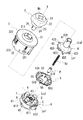
- FIG. 1 is a diagram for explaining a multidirectional switch 1
- (A) is a perspective view of the multidirectional switch 1
- (B) is a plane that passes through the reference axis X in FIG.
- FIG. 3 is a cross-sectional view of the multidirectional switch 1 cut away.
- 2 is a cross-sectional view of the multidirectional switch 1
- FIG. 2A is a cross-sectional view of the multidirectional switch 1 cut along a plane B in FIG. 1A
- FIG. FIG. 6 is a cross-sectional view taken along the line AA, with members (springs Sp and pins P) located inside the cylindrical portion 63 of the pole board 6 omitted.
- FIG. 3 is an exploded perspective view of the multidirectional switch 1.
- the knob 2 side in FIG. 1B is referred to as “upper”
- the pole board 6 side is referred to as “lower”.
- the multidirectional switch 1 includes a knob 2, a case 3, a movable board 4, an operation member 5, and a pole board 6.
- the pole board 6 which has the board
- tact switches A to D are arranged at intervals of 90 degrees in the circumferential direction around the reference axis X.
- Each of the tact switches A to D includes pressing portions 51A to 51D of the operation member 5. Is placed.
- the multidirectional switch 1 when the knob 2 in the neutral position is operated and tilted with respect to the reference axis X, the movable platen 4 connected to the knob 2 is pressed by the pressing portions 51A to 51D on the operation direction side of the knob 2.
- the corresponding tact switches A to D are selectively turned on by depressing.
- the knob 2 includes a head portion 21 having a mark Mk indicating an operation direction of the knob 2 on the upper surface, and a peripheral wall portion 22 that surrounds the outer periphery of the head portion 21 over the entire circumference.
- a cylindrical wall portion 23 extending from the inner diameter side of the peripheral wall portion 22 to the lower side of the electrode plate 6 side than the peripheral wall portion 22, and a cylindrical shape extending from the center of the head portion 21 toward the electrode plate 6 side along the reference axis X.
- a shaft portion 24 is extending from the inner diameter side of the peripheral wall portion 22 to the lower side of the electrode plate 6 side than the peripheral wall portion 22.
- a cylindrical locking portion 24 a extends downward from the head portion 21, and one end of a spring Sp is extrapolated to the locking portion 24 a.
- a pin P having a U-shaped cross section is attached to the other end side of the spring Sp.
- the pin P protrudes downward from the lower end of the shaft portion 24 and has a semicircular spherical tip portion.
- the contact portion 631 of the pole board 6 to be described later is in contact.
- Locking holes 25 and 25 are provided below the shaft portion 24 so as to penetrate the shaft portion 24 in the radial direction.
- the locking holes 25 and 25 are provided at an interval of 180 degrees in the circumferential direction around the reference axis X.
- FIG. 4A and 4B are diagrams illustrating the movable platen 4, where FIG. 4A is a perspective view seen from the lower side of the pole board 6, and FIG. 4B is a plan view seen from the lower side of the pole board 6. ) Is a plan view seen from above the knob 2 side, and (D) is a side view seen from the direction of arrows AA in (C).
- the movable platen 4 includes a cylindrical connecting portion 41 and an operation portion 42 extending in the radial direction from the lower portion of the connecting portion 41 on the pole plate 6 side.
- the operation unit 42 has a square basic shape when viewed from the axial direction, and is provided with chamfered portions 421 at four corners.
- Each of the side edge portions 422 facing each other across the reference axis X of the operation portion 42 is provided with a guide piece 423 protruding outward in the radial direction.
- the guide pieces 423 have a substantially rectangular shape when viewed from the axial direction, and extend from the central portion in the longitudinal direction of the side edge portion 422 with equal widths. These guide pieces 423 are located on the preset tilt direction side of the knob 2, and in the embodiment, they are located on the line segments Ln1 and Ln2 that pass through the reference axis X and are orthogonal to each other.
- these guide pieces 423 are inserted between guide walls 316a and 316a (see FIG. 5B) of a guide portion 316 described later when the movable platen 4 is assembled to the case 3, and the movable platen 423 is inserted. 4 is prevented from rotating around the reference axis X, and the tilt of the movable platen 4 with respect to the reference axis X is guided by the guide piece 423 moving up and down between the guide walls 316a and 316a. Yes.
- a semicircular protrusion 424 is provided on the inner diameter side of the guide piece 423 so as to protrude downward on the pole board 6 side.
- the protrusions 424 are provided in the same number as the tact switches A to D. In the embodiment, four protrusions 424 are provided at intervals of 90 degrees in the circumferential direction around the reference axis X.
- the protrusion 424 is also located on the tilting direction side of the knob 2, and is located on the line segments Ln1 and Ln2 that pass through the reference axis X and are orthogonal to each other in the embodiment. Further, each of the protrusions 424 comes into contact with the pressing portions 51A to 51D of the operation member 5 described later from the axial direction of the reference axis X when the movable platen 4 is assembled to the case 3. .
- the projections 424 located on the tilting direction side push the corresponding pressing portions 51A to 51D of the operating member 5 downward on the pole plate 6 side. It is supposed to be.
- a restricting portion 425 for guiding the tilting direction of the knob 2 in a predetermined direction is provided so as to protrude downward on the pole board 6 side.
- Four restricting portions 425 are provided at intervals of 90 degrees in the circumferential direction around the reference axis X, and the tilting direction determined in advance is restricted by tilting the knob 2 in the direction in which the restricting portion 425 is provided. It is provided for guiding in the direction of the line segments Ln1 and Ln2. The operation of the restricting portion 425 will be described in detail later.
- a slit 426 extending in the axial direction along the reference axis X is formed at the upper end of the connecting portion 41.
- Three slits 426 are provided at intervals of 90 degrees in the circumferential direction around the reference axis X, and the guide piece 423 is located on the radially outer side of the slit 426 when viewed from the axial direction of the reference axis X.
- an engaging portion 427 extending downward on the pole board 6 side is connected to the lower end of the connecting portion 41.
- Two engaging portions 427 are provided at intervals of 180 ° in the circumferential direction around the reference axis X, and a claw 427 a is formed at the tip of the engaging portion 427 so as to protrude toward the reference axis X side.
- the claw 427 a of the engaging portion 427 engages with a locking hole 25 provided in the shaft portion 24 of the knob 2 when the movable platen 4 and the knob 2 are connected.
- the knob 2 is prevented from falling off the movable platen 4.
- An arc-shaped wall portion 429 formed in an arc shape when viewed from the axial direction is provided in a portion between the engaging portions 427 and 427 at the lower portion of the connecting portion 41.
- spherical contact portions 430 are provided in cross-sectional view, and three contact portions 430 are provided at equal intervals in the circumferential direction around the reference axis X. .
- These contact portions 430 come into contact with the sliding portion 632 provided on the pole plate 6 from the axial direction of the reference axis X when the movable platen 4 is incorporated in the main body case 8 (FIG. 2). (See (A)).
- a diameter-increasing portion 428 that increases in diameter as it goes downward on the pole board 6 side is provided on the operation portion 42 side of the connecting portion 41.
- the connecting portion 41 is connected to the operation portion 42 through the enlarged diameter portion 428.
- the outer peripheral surface 428 a of the enlarged diameter portion 428 has a curved surface shape.
- the movable platen 4 contacts the outer peripheral surface 428 a of the enlarged diameter portion 428 with the contact portion 314 of the case 3. It is provided in contact.
- the contact portion 314 of the case 3 slides on the outer peripheral surface 428a (see FIG. 1B).
- FIG. 5A and 5B are diagrams for explaining the case 3, wherein FIG. 5A is a perspective view seen from the lower side of the pole board 6 side, FIG. 5B is a plan view seen from the lower side of the pole board 6 side, and FIG. These are the top views seen from the upper part by the side of the knob 2, (D) is a side view.
- the basic shape of the case 3 is a bottomed cylindrical shape, and the ring-shaped wall portion 31 that constitutes the upper wall portion of the main body case 8, and from the outer peripheral side of the wall portion 31 to the lower side on the pole board 6 side. And a cylindrical peripheral wall portion 32 that extends.
- a through hole 310 is provided in the central portion of the wall portion 31 so as to penetrate the wall portion 31 in the thickness direction, and a boss portion that surrounds the through hole 310 over the entire circumference on the upper surface of the wall portion 31. 311 is formed to protrude upward on the knob 2 side.
- the radial width W of the boss portion 311 in a cross-sectional view becomes narrower toward the upper side.
- the upper end 311a side of the boss portion 311 is located on the inner diameter side of the cylindrical wall portion 23 of the knob 2, and prevents foreign matters such as dust from entering the through hole 310 side.
- a concave groove 312 surrounding the through hole 310 is formed on the lower surface of the boss portion 311, and the inner diameter side of the concave groove 312 serves as an abutting portion 313 with the enlarged diameter portion 428 of the movable platen 4. Yes.
- a contact portion 314 with the enlarged-diameter portion 428 of the movable platen 4 is provided at a lower portion on the inner diameter side of the abutting portion 313, and a surface facing the enlarged-diameter portion 428 of the contact portion 314 has an enlarged diameter. It is formed in an arc shape so as to match the outer diameter of the portion 428.
- the abutment portion 313 is cantilevered by the wall portion 31 by the concave groove 312 provided in the wall portion 31, and the contact portion 314 of the abutment portion 313 is provided below.
- the side can be displaced in the radial direction. Therefore, the diameter-enlarged portion 428 of the movable platen 4 is elastically supported by the contact portion 313 so that the tilting of the movable platen 4 that is interlocked with the operation of the knob 2 is not hindered.
- a rib 315 extending to the tilting direction side of the knob 2 is connected to the contact portion 313, and the rib 315 connects the contact portion 313 on the contact portion 314 side. The amount of displacement is prevented from becoming too large.
- the peripheral wall 32 extends downward from the outer periphery of the wall 31 toward the inner diameter side, and extends downward on the pole board 6 side.
- a locking hole 321 that penetrates the peripheral wall portion 32 in the thickness direction and a notch 323 are provided.
- the locking holes 321 are provided at three locations spaced in the circumferential direction around the reference axis X.
- each of the locking holes 321 is provided with the pole board 6.
- a locking claw 611 (see FIG. 3) engages to prevent the case 3 from falling off the pole board 6.
- two notches 323 are provided at intervals in the circumferential direction around the reference axis X.
- the mating protrusion 612 (see FIG. 3) is engaged so that the case 3 is prevented from rotating with respect to the pole board 6.
- each guide portion 316 includes a pair of guide walls 316 a and 316 a, and these guide walls 316 a and 316 a extend downward along the inner periphery of the peripheral wall portion 32 on the pole board 6 side.
- the guide walls 316a and 316a are formed with a length extending in the vicinity of the tact switches A to D of the pole board 6 (see FIG. 2A), and a movable board is interposed between the guide walls 316a and 316a.
- the guide unit 316 guides the movement (tilt) of the movable plate 4 in the axial direction of the movable platen 4 that is tilted in conjunction with the operation of the knob 2, and the circumference of the movable platen 4 around the reference axis X It is provided to regulate the rotation of the direction.
- a locking claw 322 for fixing the multidirectional switch 1 to the counterpart member is provided at a position that is symmetrical with respect to the reference axis X.
- Two locking claws 322 are provided at intervals of 180 degrees in the circumferential direction around the reference axis X, and when viewed from the axial direction of the reference axis X, the locking claws 322 are adjacent to the guide portions 316, 316, 316.
- Each locking claw 322 is cantilevered by the peripheral wall portion 32 at the lower side on the pole board 6 side, and the upper side at the wall portion 31 side can be elastically deformed in the radial direction of the reference axis X.
- the electrode plate 6 has a base 61 to which a substrate 7 is attached on the surface facing the case 3, and a lower portion of the base 61 opens in the radial direction of the reference axis X.
- a connector portion 62 is provided.
- the connection terminal 621 extending from the connector portion 62 is embedded in the pole board 6 by insert molding, and the distal end side of the connection terminal 621 extends in the axial direction of the reference axis X. After that, it is soldered to the upper surface of the substrate 7 (see FIG. 2B).
- Tact switches A to D are attached to the upper surface of the substrate 7 on the case 3 side.
- the tact switches A to D are push-type switch elements that are turned on when they are pressed and moved in the axial direction of the reference axis X.
- an opening 71 (see FIG. 2B) through which the cylindrical portion 63 extending upward from the pole board 6 on the case 3 side is inserted is provided. It is provided so as to surround (cylindrical portion 63).
- the tact switches A to D are provided at intervals of 90 degrees in the circumferential direction around the reference axis X.
- the inside of the cylindrical portion 63 is recessed in a mortar shape, the central portion on the reference axis X side is the contact portion 631 of the pin P supported by the shaft portion 24 of the knob 2, and the periphery of the contact portion 631 is The sliding portion 632 of the contact portion 430 provided on the arc-shaped wall portion 429 of the knob 2 is formed.
- a groove 631a is formed in a cross shape in a plan view when viewed from above on the knob 2 side, and the pin P slides along the groove 631a when the knob 2 is tilted.
- the tilting direction of the knob 2 is set so as to be along the groove 631a. Therefore, in the embodiment, one of the tact switches A to D is positioned on the extension of the groove 631a.
- a pointed protrusion 64 is provided on the outer peripheral surface of the cylindrical portion 63 as viewed from the axial direction of the reference axis X so as to protrude radially outward.
- Four protrusions 64 are provided at intervals of 90 degrees in the circumferential direction around the reference axis X, and the protrusions 64 and the restricting portions 425 are arranged to face each other in the circumferential direction around the reference axis X.
- the knob 2 is tilted in four directions along the axis lines Ln1 and Ln2 to turn on the tact switches A to D.
- the knob 2 is movable.
- the restricting portion 425 of the board 4 comes into contact with the protruding portion 64 of the cylindrical portion 63 so that the movement of the knob 2 in that direction is restricted.
- FIG. 6A and 6B are diagrams for explaining the operation of the restricting portion 425.
- FIG. 6A shows a case where the knob 2 is tilted in a direction other than the preset tilt direction (in the direction of the line segment Ln3). It is a figure explaining the case where the knob 2 is tilted in the preset tilt direction (the direction of the line segment Ln2 and the direction in which the tact switch B is turned on).
- the knob 2 is further operated so that the restricting portion 425 is on the black arrow F side.
- the tip end portion 425a moves along one of the inclined surfaces 64a and 64b of the protruding portion 64.
- the restricting portion 425 moves in the direction of the arrows Fa and Fb in the drawing, that is, the direction in which the knob 2 is moved in a preset direction (direction of the line segment Ln1 or Ln2).
- the tact switches A to D positioned on the operation direction side are turned on.
- the restricting portion 425 comes into contact with the protruding portion 64, so that the operation of the knob 2 in that direction is prevented, and then the slope of the protruding portion 64
- the knob 2 is guided in a preset direction by 64a and 64b.
- the pressing portions 51 (51A to 51D) of the operation member 5 are placed on the upper surface on the case 3 side.
- FIG. 7A and 7B are diagrams illustrating the operation member 5, where FIG. 7A is a perspective view seen from the lower side of the pole board 6 side, and FIG. 7B is a plan view seen from the lower side of the pole board 6 side. ) Is a plan view seen from above the knob 2 side, (D) is a side view, and (E) is a state of the operation member 5 when the pressing portion 51C is moved downward on the substrate 7 side. It is a figure to do.
- the pressing portion 51 of the operation member 5 is provided to uniformly transmit the urging force acting from the protrusion 424 of the movable platen 4 to the upper surfaces of the tact switches A to D.
- the operation member 5 includes a placement portion 510 placed on the upper surfaces of the duct switches A to D, and side wall portions 511 and 511 extending downward from both sides of the placement portion 510 in the circumferential direction around the reference axis X toward the substrate 7 side. And leg portions 512 and 512 projecting toward the substrate 7 from the lower ends of the side wall portions 511 and 511 on the substrate 7 side, and these are integrally formed from a flexible material.
- the protrusion 424 of the movable platen 4 protrudes from the lower surface of the operation unit 42 on the pole plate 6 side. Therefore, if the urging force (operation force) input from the operation unit 42 is directly input from the protrusion 424 to the corresponding tact switches A to D without providing the operation member 5, the protrusion 424 responds. Since the tactile switches A to D are brought into point contact with each other, the input urging force is concentrated on one point, and the tact switches A to D may be damaged.
- the operation member 5 (pressing part 51) made of a flexible material is interposed between the protrusion 424 and the tact switches A to D, so that the input urging force is applied to the tact switch. The tact switches A to D are prevented from being damaged while being uniformly transmitted to the upper surfaces of A to D.
- the mounting portion 510 has a substantially rectangular shape in plan view, and projections 513 and 513 are formed on the opposing surfaces of the side wall portions 511 and 511 extending downward from the mounting portion 510 on the pole board 6 side. Is provided.
- the projection part 513 is provided in the side wall part 511, and the projection part 513, 513 of one side wall part 511 and the projection of the other side wall part 511 in plan view. The parts 513 and 513 hold the rectangular corners of the tact switches A to D.
- the pressing portions 51 are provided at 90 degree intervals in the circumferential direction around the reference axis X, and the pressing portions 51 and 51 adjacent in the circumferential direction are wavy when viewed from the radial direction of the reference axis X.
- the flexible connection pieces 55 are connected to each other.
- the connection piece 55 has an arc shape when viewed from the axial direction of the reference axis X, and has a shape along a virtual circle Im1 having a predetermined radius r centered on the reference axis X ((C in FIG. 7). )reference).
- the pressing portions 51 (51A to 51D) are provided so as to protrude to the inner diameter side from the virtual circle Im1, and a space for providing the cylindrical portion 63 of the pole board 6 is secured on the inner diameter side of these pressing portions 51. ing.
- the connecting piece 55 has a wave shape in which peaks and valleys are alternately continuous in the circumferential direction of the reference axis X (a shape that undulates in the axial direction of the reference axis X).
- the pressing portions 51 (51A to 51D) can be moved independently in the axial direction of the reference axis X. For example, when the pressing portion 51C is pressed downward on the substrate 7 (electrode board 6) side by the operation of the knob 2, as shown in FIG.
- connection piece 55 extending from the pressing portion 51C
- the other pressing parts 51B and 51D adjacent to the pressing part 51C do not move downward on the substrate 7 side following the movement of the pressing part 51C. Yes.
- the side walls 511 of the pressing portion 51C are provided with leg portions 512 and 512 protruding downward on the substrate 7 side, when the pressing portion 51C moves to the substrate 7 side by the operation of the knob 2, the pressing portion 51C The movement of the portion 51C ends at a position where the leg portions 512 and 512 are in contact with the substrate 7.
- the tact switches A to D are pushed more than necessary and are damaged. Is preventing. Specifically, the length L from the mounting portion 510 to the tip of the leg portion 512 (see FIG. 7D), the pressing portion 51 (51A to 51D), and the tact switches A to D on the substrate 7 side.
- the tact switches A to D having been stroked are turned on, the length is set such that the leg 512 abuts against the substrate 7.
- the recessed parts 510a and 510a are provided in the both sides in the width direction.
- the concave portions 510a and 510a are recessed below the contact plate 510 side with respect to the contact portion 510b with which the protrusion 424 of the movable plate 4 contacts, and overlap the connection piece 55 when viewed from the axial direction of the reference axis X. It is located on the virtual circle Im1.
- the recesses 510a and 510a of the pressing portion 51A are guide pieces located on the pressing portion 51A side of the movable platen 4 when the movable platen 4 is tilted in a direction to push the pressing portion 51B or the pressing portion 51D down to the pole plate 6 side. 423 (see FIG. 4C) is provided to prevent interference with the placement portion 510.
- FIGS. 8A and 8B are diagrams for explaining a case where the knob 2 is tilted in the direction in which the tact switch D is turned on.
- FIG. 8A is a cross-sectional view of the multi-directional switch 1
- FIG. FIG. 6 is a diagram for explaining the relationship between the control member and the operating member.
- the movable board 4 connected to the knob 2 moves the guide piece 423 on the tact switch D side to the pole board 6 side. Tilt in the direction to move it down. Then, the pin P biased by the spring Sp slides on the contact portion 631 of the pole board 6 so that a sense of moderation is imparted to the operation of the knob 2.
- the operation unit 42 is tilted while moving the guide piece 423 downward between the guide walls 316 a and 316 a provided in the case 3, and the projecting portion 424 provided at the lower part of the operation unit 42 is operated by the operation member 42.
- the five pressing portions 51D (mounting portion 510) and the tact switch D on which the pressing portions 51D are mounted are moved downward on the pole board 6 side to turn on the tact switch D.
- the pressing portion 51D is connected to another pressing portion 51C and a pressing portion 51A (not shown) adjacent in the circumferential direction around the reference axis X via a connection piece 55.
- the connecting piece 55 extending from the pressing part 51D extends in the longitudinal direction while reducing the amplitude of the wave shape, so that the other pressing parts 51C and 51A adjacent to the pressing part 51D are provided.
- the pressing portion 51D it does not move downward on the pole board 6 side.
- the concave portions 510a are provided on both sides in the width direction of the placement portion 510, so that the operation portion 42 is tilted.
- the guide piece 423 on the pressing portion 51C side that is inclined in this manner interferes with the pressing portion 51C so as not to turn on the tact switch C located below the pressing portion 51C. Therefore, the other tact switches A and C adjacent to the tact switch D that should be turned on can be prevented from being turned on.
- the pressing portion 51 positioned on the operation direction side of the knob 2. (51A to 51D) is moved in the axial direction of the reference axis X, and the tactile switches A to D (switch elements) corresponding to the moved pressing portions 51 (51A to 51D) are selectively turned on.
- the tactile switches A to D and four pressing portions 51 (51A to 51D) are provided in the circumferential direction around the reference axis X at intervals of 90 degrees, and the pressing portions 51 (51A to 51D) are provided with reference shafts.
- a multi-directional configuration in which the other pressing portions 51 (51A to 51d) adjacent in the circumferential direction of X are connected to each other by a flexible connecting piece 55 formed in a wave shape when viewed from the radial direction of the reference axis X Switch 1 was designated.
- the knob 2 When the knob 2 is in the neutral position, it has an operation portion 42 that is positioned orthogonal to the reference axis X, and when the knob 2 is operated, the operation portion 42 side of the knob 2 in the operation portion 42 is viewed from the reference axis X.
- a movable platen 4 (movable member) that is tilted by moving it toward the pole plate 6 in the axial direction of the reference axis X
- a protruding portion 424 (abutted on the pressing portion 51 (51A to 51D) on the direction side (on the line segments Ln1 and Ln2) preset as the operation direction of the knob 2
- a restricting portion 425 (blocking portion) that prevents the movable platen 4 from being tilted is provided on a direction side that is not preset as the operation direction of the knob 2, and the knob 2 is connected to the knob 2.
- the restricting portion 425 comes into contact with the protruding portion 64 (fixed-side stopper) of the pole board 6 and the knob 2 is not set in the predetermined direction side.
- the inclined surface 64a that guides the tilting direction of the movable platen 4 to the direction set in advance as the operation direction of the knob 2 on the contact surface of the projecting portion 64 with the restricting portion 425. , 64b is provided.
- the tact switches A to D are switch elements configured to be turned on when a predetermined amount of stroke is applied to the substrate 7 by the pressing portions 51 (51A to 51D).
- the pressing portions 51 (51A to 51D) are provided with a mounting portion 510 (contact portion) placed on the upper surface opposite to the substrate 7 of the tact switches A to D, and a tact switch from the side edge of the placement portion 510.
- a leg portion 512 extending to the side of the substrate 7 through the sides A to D;
- the length L of the leg portion 512 from the placement portion 510 is in contact with the substrate 7 when the tact switches A to D are pressed toward the substrate 7 and stroked by a predetermined amount, so that the pressing portions 51 (51A to 51D) It was set as the structure formed in the length which prevents the movement to the board
Landscapes
- Switches With Compound Operations (AREA)
Abstract
[Problem] To provide a clicking mechanism on the central shaft of a knob without increasing the size of a multi-directional switch in the radial direction.
[Solution] A multi-directional switch (1) is configured such that when a knob (2) at a neutral position is manipulated and tilted with respect to a reference axis (X) for the neutral position of the knob, a pressing part (51) (51A - 51D) located on the side in the manipulation direction moves in the axial direction of the reference axis (X) so that the pressing part selectively turns on a tactile switch (A - D) (switching element) corresponding to the pressing part (51) (51A - 51D) that moved. Four tactile switches (A - D) and four pressing parts (51) (51A - 51D) are respectively provided circumferentially around the reference axis (X) at an interval of 90 degrees, and a pressing part (51) (51A - 51D) and another pressing part (51) (51A - 51D) adjacent thereto in the circumferential direction of the reference axis (X) are connected to each other via a flexible connection piece (55) that is formed into a corrugated shape when viewed from a radial direction of the reference axis (X).
Description
本発明は、ノブを所定方向に傾倒操作することで、スイッチ素子を選択的にオンさせる多方向スイッチに関する。
The present invention relates to a multidirectional switch that selectively turns on a switch element by tilting a knob in a predetermined direction.
特許文献1には、ノブを所定方向に傾倒操作することで、ハウジング内のスイッチ素子を選択的にオンさせる多方向スイッチが開示されている。
Patent Document 1 discloses a multidirectional switch that selectively turns on a switch element in a housing by tilting a knob in a predetermined direction.
図9は、従来の多方向スイッチの要部を分解して示す斜視図である。
この多方向スイッチでは、弾性の支持部材100の支持部101に可動接点102が取り付けられており、この支持部101が、ノブの操作に連動して進退移動する棒状の操作部材103により押されて移動することで、支持部101に支持された可動接点102が、プリント基板104の表面に設けられた固定接点105に対して接離するようになっている。 FIG. 9 is an exploded perspective view showing a main part of a conventional multidirectional switch.
In this multidirectional switch, amovable contact 102 is attached to a support portion 101 of an elastic support member 100, and this support portion 101 is pushed by a rod-like operation member 103 that moves forward and backward in conjunction with the operation of a knob. By moving, the movable contact 102 supported by the support portion 101 comes into contact with and is separated from the fixed contact 105 provided on the surface of the printed circuit board 104.
この多方向スイッチでは、弾性の支持部材100の支持部101に可動接点102が取り付けられており、この支持部101が、ノブの操作に連動して進退移動する棒状の操作部材103により押されて移動することで、支持部101に支持された可動接点102が、プリント基板104の表面に設けられた固定接点105に対して接離するようになっている。 FIG. 9 is an exploded perspective view showing a main part of a conventional multidirectional switch.
In this multidirectional switch, a
プリント基板104において固定接点105は、ノブの基準軸X周りの周方向に所定間隔で複数設けられており、基準軸Xの軸方向から見てリング状に配置されている。
可動接点102と操作部材103もまた、ノブの基準軸X周りの周方向に所定間隔で複数設けられており、基準軸Xの軸方向から見てリング状に配置されている。 In theprinted circuit board 104, a plurality of fixed contacts 105 are provided at predetermined intervals in the circumferential direction around the reference axis X of the knob, and are arranged in a ring shape when viewed from the axial direction of the reference axis X.
A plurality ofmovable contacts 102 and operation members 103 are also provided at a predetermined interval in the circumferential direction around the reference axis X of the knob, and are arranged in a ring shape when viewed from the axial direction of the reference axis X.
可動接点102と操作部材103もまた、ノブの基準軸X周りの周方向に所定間隔で複数設けられており、基準軸Xの軸方向から見てリング状に配置されている。 In the
A plurality of
そのため、ノブが所定方向に傾倒操作されて、操作方向側に位置する操作部材103が基準軸Xの軸方向に移動すると、移動した操作部材103により押された支持部101の可動接点102が、固定接点105に接するようになっている。
Therefore, when the knob is tilted in a predetermined direction and the operation member 103 located on the operation direction side moves in the axial direction of the reference axis X, the movable contact 102 of the support portion 101 pressed by the moved operation member 103 is It comes in contact with the fixed contact 105.
ここで、各操作部材103が独立していると、多方向スイッチの組付け性が悪くなるので、各操作部材103は、基準軸Xの周方向で隣接する他の操作部材103に、薄板状の接続片106、107を介して接続されている。
Here, when each operation member 103 is independent, the assembling property of the multi-directional switch is deteriorated. Therefore, each operation member 103 is formed in a thin plate shape with another operation member 103 adjacent in the circumferential direction of the reference axis X. The connection pieces 106 and 107 are connected.
しかし、基準軸Xの周方向で隣接する操作部材103同士を単純に接続すると、ある操作部材103が基準軸Xの軸方向に移動した際に、この操作部材103に隣接する他の操作部材103が引っ張られて、移動した操作部材103と同方向に移動してしまうことがある。
かかる場合、本来接触させるべき可動接点102点の他に、この可動接点102に隣接する他の可動接点102も、対応する固定接点105に接触してしまうことがある。 However, when theoperation members 103 adjacent in the circumferential direction of the reference axis X are simply connected, when another operation member 103 moves in the axial direction of the reference axis X, another operation member 103 adjacent to the operation member 103 is obtained. May be pulled in the same direction as the operation member 103 that has moved.
In such a case, in addition to themovable contact 102 that should be originally contacted, another movable contact 102 adjacent to the movable contact 102 may also come into contact with the corresponding fixed contact 105.
かかる場合、本来接触させるべき可動接点102点の他に、この可動接点102に隣接する他の可動接点102も、対応する固定接点105に接触してしまうことがある。 However, when the
In such a case, in addition to the
そのため、特許文献1の場合、接続片106、107のうちの一方の接続片107を長くして、ある操作部材103が移動したときに、この操作部材103の移動に追従して、隣接する他の操作部材103が移動しないようにしている。
Therefore, in the case of Patent Document 1, when one operation member 103 is moved by lengthening one of the connection pieces 106 and 107, the movement of the operation member 103 is followed and the other The operation member 103 is prevented from moving.
ここで、多方向スイッチの径方向の大きさは限られているので、接続片107は、その長さを確保するために、基準軸X側を迂回して、隣接する操作部材103同士を接続している。そのため、接続片107は、軸方向から見て略V字形状に形成されており、その尖状の屈曲部107aは、基準軸Xの近傍に位置している。
Here, since the radial size of the multidirectional switch is limited, the connection piece 107 bypasses the reference axis X side and connects adjacent operation members 103 to ensure the length. is doing. Therefore, the connection piece 107 is formed in a substantially V shape when viewed in the axial direction, and the sharp bent portion 107 a is located in the vicinity of the reference axis X.
ここで、多方向スイッチにおいて、プリント基板を支持する極盤(図示せず)の中央に凹状の節度溝を設け、この節度溝に、ノブから延びる節度ピンを基準軸上で係合させて、ノブの傾倒操作に節度感を持たせようとすると、例えば、図9の(C)において仮想線で示す位置に節度溝108が配置されることになる。
そうすると、基準軸X側に突出する接続片107の屈曲部107aが、節度溝108に干渉してしまう。
かかる場合、節度溝108との干渉を避けるために、接続片107を短くして基準軸X側への突出量を抑えることが考えられる。しかし、接続片107が短くなると、ある操作部材103の移動に追従して隣接する他の操作部材103が移動することを防止できなくなり、予定していない可動接点102が対応する固定接点105に接触してしまう虞がある。
また、接続片107を径方向外側に延ばすことが考えられるが、この場合には、多方向スイッチが径方向に大型化してしまう。 Here, in the multi-directional switch, a concave moderation groove is provided in the center of a pole board (not shown) that supports the printed circuit board, and a moderation pin extending from the knob is engaged with the moderation groove on the reference axis. In order to give a sense of moderation to the tilting operation of the knob, for example, the moderation groove 108 is arranged at a position indicated by a virtual line in FIG. 9C.
Then, thebent portion 107a of the connection piece 107 protruding toward the reference axis X side interferes with the moderation groove 108.
In such a case, in order to avoid interference with the moderation groove 108, it is conceivable to shorten the connectingpiece 107 to suppress the amount of protrusion toward the reference axis X side. However, if the connecting piece 107 is shortened, it becomes impossible to prevent the movement of the other adjacent operation member 103 following the movement of a certain operation member 103, and the unscheduled movable contact 102 contacts the corresponding fixed contact 105. There is a risk of it.
Although it is conceivable to extend the connectingpiece 107 radially outward, in this case, the multi-directional switch is enlarged in the radial direction.
そうすると、基準軸X側に突出する接続片107の屈曲部107aが、節度溝108に干渉してしまう。
かかる場合、節度溝108との干渉を避けるために、接続片107を短くして基準軸X側への突出量を抑えることが考えられる。しかし、接続片107が短くなると、ある操作部材103の移動に追従して隣接する他の操作部材103が移動することを防止できなくなり、予定していない可動接点102が対応する固定接点105に接触してしまう虞がある。
また、接続片107を径方向外側に延ばすことが考えられるが、この場合には、多方向スイッチが径方向に大型化してしまう。 Here, in the multi-directional switch, a concave moderation groove is provided in the center of a pole board (not shown) that supports the printed circuit board, and a moderation pin extending from the knob is engaged with the moderation groove on the reference axis. In order to give a sense of moderation to the tilting operation of the knob, for example, the moderation groove 108 is arranged at a position indicated by a virtual line in FIG. 9C.
Then, the
In such a case, in order to avoid interference with the moderation groove 108, it is conceivable to shorten the connecting
Although it is conceivable to extend the connecting
そのため、多方向スイッチにおいて、スイッチ素子が誤ってオンされないようにしつつ、かつ径方向に大型化させることなく、ノブの基準軸上に節度機構を設けられるようにすることが求められている。
Therefore, in a multidirectional switch, it is required to provide a moderation mechanism on the reference axis of the knob while preventing the switch element from being turned on accidentally and without increasing the size in the radial direction.
本発明は、
中立位置にあるノブが操作されて、前記ノブが前記中立位置にあるときの基準軸に対して傾くと、前記ノブの操作方向側に位置する押圧部が前記基準軸の軸方向に移動して、当該押圧部に対応するスイッチ素子を選択的にオンさせる多方向スイッチにおいて、
前記スイッチ素子と前記押圧部は、前記基準軸回りの周方向に所定間隔で、同数ずつ設けられており、
前記基準軸回りの周方向で隣接する押圧部同士は、基準軸の径方向から見て波状に形成された可撓性の接続片で互いに接続されていることを特徴とする多方向スイッチとした。 The present invention
When the knob in the neutral position is operated and the knob is tilted with respect to the reference axis when the knob is in the neutral position, the pressing portion located on the operation direction side of the knob moves in the axial direction of the reference axis. In the multi-directional switch that selectively turns on the switch element corresponding to the pressing portion,
The switch elements and the pressing portions are provided in equal numbers at predetermined intervals in the circumferential direction around the reference axis,
The pressing portions adjacent in the circumferential direction around the reference axis are connected to each other by a flexible connection piece formed in a wave shape when viewed from the radial direction of the reference axis. .
本発明によれば、基準軸周りの周方向で隣接する操作部同士を接続する接続片を、基準軸の径方向から見て波状に形成したので、操作ノブの傾倒方向に位置する操作部が基準軸の軸方向に移動したときに、接続片が延びることで、この移動した操作部に隣接する他の操作部が追従して移動することを防止できる。これによりスイッチ素子が誤ってオンされることを防止できる。
また、接続片が基準軸の軸方向に波打つような形成を有しているので、接続片の長さを長くしても、接続片を収容する空間を基準軸側に設ける必要がないので、基準軸側に節度機構を設けるための空間を確保できる。 According to the present invention, since the connecting piece that connects the operation units adjacent in the circumferential direction around the reference axis is formed in a wave shape when viewed from the radial direction of the reference axis, the operation unit positioned in the tilting direction of the operation knob is provided. When the connection piece extends when moved in the axial direction of the reference axis, it is possible to prevent other operation units adjacent to the moved operation unit from following and moving. This can prevent the switch element from being turned on by mistake.
In addition, since the connection piece has a formation that undulates in the axial direction of the reference axis, it is not necessary to provide a space for accommodating the connection piece on the reference axis side even if the length of the connection piece is increased. A space for providing a moderation mechanism on the reference shaft side can be secured.
図1は、多方向スイッチ1を説明する図であり、(A)は、多方向スイッチ1の斜視図であり、(B)は、(A)における基準軸Xを通り面Aに直交する面で、多方向スイッチ1を、切断した断面図である。
図2は、多方向スイッチ1の断面図であり、(A)は、図1の(A)における面Bで多方向スイッチ1を切断した断面図であり、(B)は、(A)におけるA-A断面図であって、極盤6の円筒部63の内側に位置する部材(スプリングSp、ピンP)の図示を省略した図である。
図3は、多方向スイッチ1の分解斜視図である。
なお、以下の説明では、説明の便宜上、図1の(B)におけるノブ2側を「上方」、極盤6側を「下方」と表記する。 FIG. 1 is a diagram for explaining amultidirectional switch 1, (A) is a perspective view of the multidirectional switch 1, and (B) is a plane that passes through the reference axis X in FIG. FIG. 3 is a cross-sectional view of the multidirectional switch 1 cut away.
2 is a cross-sectional view of themultidirectional switch 1, FIG. 2A is a cross-sectional view of the multidirectional switch 1 cut along a plane B in FIG. 1A, and FIG. FIG. 6 is a cross-sectional view taken along the line AA, with members (springs Sp and pins P) located inside the cylindrical portion 63 of the pole board 6 omitted.
FIG. 3 is an exploded perspective view of themultidirectional switch 1.
In the following description, for convenience of description, theknob 2 side in FIG. 1B is referred to as “upper”, and the pole board 6 side is referred to as “lower”.
図2は、多方向スイッチ1の断面図であり、(A)は、図1の(A)における面Bで多方向スイッチ1を切断した断面図であり、(B)は、(A)におけるA-A断面図であって、極盤6の円筒部63の内側に位置する部材(スプリングSp、ピンP)の図示を省略した図である。
図3は、多方向スイッチ1の分解斜視図である。
なお、以下の説明では、説明の便宜上、図1の(B)におけるノブ2側を「上方」、極盤6側を「下方」と表記する。 FIG. 1 is a diagram for explaining a
2 is a cross-sectional view of the
FIG. 3 is an exploded perspective view of the
In the following description, for convenience of description, the
図1から図3に示すように、実施の形態にかかる多方向スイッチ1は、ノブ2と、ケース3と、可動盤4と、操作部材5と、極盤6とを備えており、ケース3と、このケース3との対向面に基板7を有する極盤6とが、ノブ2の基準軸X(中立軸)の軸方向で組み付けられて本体ケース8を構成している。
As shown in FIGS. 1 to 3, the multidirectional switch 1 according to the embodiment includes a knob 2, a case 3, a movable board 4, an operation member 5, and a pole board 6. And the pole board 6 which has the board | substrate 7 in the surface facing this case 3 is assembled | attached by the axial direction of the reference axis X (neutral axis) of the knob 2, and the main body case 8 is comprised.
基板7の上面には、基準軸X回りの周方向に90度間隔で、タクトスイッチA~Dが配置されており、タクトスイッチA~Dの各々には、操作部材5の押圧部51A~51Dが載置されている。
多方向スイッチ1では、中立位置にあるノブ2が操作されて基準軸Xに対して傾くと、このノブ2に連結された可動盤4が、ノブ2の操作方向側にある押圧部51A~51Dを押し下げて、対応するタクトスイッチA~Dを選択的にオンさせるようになっている。 On the upper surface of thesubstrate 7, tact switches A to D are arranged at intervals of 90 degrees in the circumferential direction around the reference axis X. Each of the tact switches A to D includes pressing portions 51A to 51D of the operation member 5. Is placed.
In themultidirectional switch 1, when the knob 2 in the neutral position is operated and tilted with respect to the reference axis X, the movable platen 4 connected to the knob 2 is pressed by the pressing portions 51A to 51D on the operation direction side of the knob 2. The corresponding tact switches A to D are selectively turned on by depressing.
多方向スイッチ1では、中立位置にあるノブ2が操作されて基準軸Xに対して傾くと、このノブ2に連結された可動盤4が、ノブ2の操作方向側にある押圧部51A~51Dを押し下げて、対応するタクトスイッチA~Dを選択的にオンさせるようになっている。 On the upper surface of the
In the
以下、多方向スイッチ1の各構成要素を説明する。
[ノブ2]
図1および図2に示すように、ノブ2は、上面に当該ノブ2の操作方向を示すマークMkが付されたヘッド部21と、ヘッド部21の外周を全周に亘って囲む周壁部22と、周壁部22の内径側から周壁部22よりも極盤6側の下方に延びる筒状壁部23と、ヘッド部21の中心から基準軸Xに沿って極盤6側に延びる円筒形状の軸部24とを有している。 Hereinafter, each component of themultidirectional switch 1 will be described.
[Knob 2]
As shown in FIGS. 1 and 2, theknob 2 includes a head portion 21 having a mark Mk indicating an operation direction of the knob 2 on the upper surface, and a peripheral wall portion 22 that surrounds the outer periphery of the head portion 21 over the entire circumference. A cylindrical wall portion 23 extending from the inner diameter side of the peripheral wall portion 22 to the lower side of the electrode plate 6 side than the peripheral wall portion 22, and a cylindrical shape extending from the center of the head portion 21 toward the electrode plate 6 side along the reference axis X. And a shaft portion 24.
[ノブ2]
図1および図2に示すように、ノブ2は、上面に当該ノブ2の操作方向を示すマークMkが付されたヘッド部21と、ヘッド部21の外周を全周に亘って囲む周壁部22と、周壁部22の内径側から周壁部22よりも極盤6側の下方に延びる筒状壁部23と、ヘッド部21の中心から基準軸Xに沿って極盤6側に延びる円筒形状の軸部24とを有している。 Hereinafter, each component of the
[Knob 2]
As shown in FIGS. 1 and 2, the
軸部24内では、円柱形状の係止部24aが、ヘッド部21から下方に向けて延びており、この係止部24aには、スプリングSpの一端が外挿されている。
スプリングSpの他端側には、断面U字形状のピンPが外挿されて取り付けられており、このピンPは、軸部24の下端から下方に突出して、その半円球状の先端部を、後記する極盤6の当接部631に当接させている。 In theshaft portion 24, a cylindrical locking portion 24 a extends downward from the head portion 21, and one end of a spring Sp is extrapolated to the locking portion 24 a.
A pin P having a U-shaped cross section is attached to the other end side of the spring Sp. The pin P protrudes downward from the lower end of theshaft portion 24 and has a semicircular spherical tip portion. The contact portion 631 of the pole board 6 to be described later is in contact.
スプリングSpの他端側には、断面U字形状のピンPが外挿されて取り付けられており、このピンPは、軸部24の下端から下方に突出して、その半円球状の先端部を、後記する極盤6の当接部631に当接させている。 In the
A pin P having a U-shaped cross section is attached to the other end side of the spring Sp. The pin P protrudes downward from the lower end of the
軸部24の下側には、軸部24を径方向に貫通して係止孔25、25が設けられている。係止孔25、25は、基準軸X回りの周方向に180度間隔で設けられており、これら係止孔25、25には、ノブ2を可動盤4に組み付けた際に、可動盤4の係止部427の爪427aが径方向から係止されて、ノブ2と可動盤4とが連結されるようになっている。
Locking holes 25 and 25 are provided below the shaft portion 24 so as to penetrate the shaft portion 24 in the radial direction. The locking holes 25 and 25 are provided at an interval of 180 degrees in the circumferential direction around the reference axis X. When the knob 2 is assembled to the movable plate 4, the movable plate 4 is inserted into the locking holes 25 and 25. The claw 427a of the locking portion 427 is locked from the radial direction so that the knob 2 and the movable platen 4 are connected.
[可動盤4]
図4は、可動盤4を説明する図であり、(A)は、極盤6側の下方から見た斜視図、(B)は、極盤6側の下方から見た平面図、(C)は、ノブ2側の上方から見た平面図、(D)は、(C)におけるA-A矢視方向から見た側面図である。 [Moving platen 4]
4A and 4B are diagrams illustrating themovable platen 4, where FIG. 4A is a perspective view seen from the lower side of the pole board 6, and FIG. 4B is a plan view seen from the lower side of the pole board 6. ) Is a plan view seen from above the knob 2 side, and (D) is a side view seen from the direction of arrows AA in (C).
図4は、可動盤4を説明する図であり、(A)は、極盤6側の下方から見た斜視図、(B)は、極盤6側の下方から見た平面図、(C)は、ノブ2側の上方から見た平面図、(D)は、(C)におけるA-A矢視方向から見た側面図である。 [Moving platen 4]
4A and 4B are diagrams illustrating the
図1の(B)に示すように、可動盤4は、円筒形状の連結部41と、連結部41の極盤6側の下部から径方向に延びる操作部42とを備える。
図4に示すように、操作部42は、軸方向から見た基本形状が正方形であり、四隅に面取り部421が設けられている。この操作部42の基準軸Xを挟んで対向する側縁部422の各々には、径方向外側に突出してガイド片423が設けられている。 As shown in FIG. 1B, themovable platen 4 includes a cylindrical connecting portion 41 and an operation portion 42 extending in the radial direction from the lower portion of the connecting portion 41 on the pole plate 6 side.
As shown in FIG. 4, theoperation unit 42 has a square basic shape when viewed from the axial direction, and is provided with chamfered portions 421 at four corners. Each of the side edge portions 422 facing each other across the reference axis X of the operation portion 42 is provided with a guide piece 423 protruding outward in the radial direction.
図4に示すように、操作部42は、軸方向から見た基本形状が正方形であり、四隅に面取り部421が設けられている。この操作部42の基準軸Xを挟んで対向する側縁部422の各々には、径方向外側に突出してガイド片423が設けられている。 As shown in FIG. 1B, the
As shown in FIG. 4, the
ガイド片423は、軸方向から見て略矩形形状を有しており、側縁部422の長手方向における中央部から、それぞれ等幅で延びている。
これらガイド片423は、ノブ2の予め設定された傾倒方向側に位置しており、実施の形態では、基準軸Xを通り互いに直交する線分Ln1、Ln2上に位置している。 Theguide pieces 423 have a substantially rectangular shape when viewed from the axial direction, and extend from the central portion in the longitudinal direction of the side edge portion 422 with equal widths.
These guidepieces 423 are located on the preset tilt direction side of the knob 2, and in the embodiment, they are located on the line segments Ln1 and Ln2 that pass through the reference axis X and are orthogonal to each other.
これらガイド片423は、ノブ2の予め設定された傾倒方向側に位置しており、実施の形態では、基準軸Xを通り互いに直交する線分Ln1、Ln2上に位置している。 The
These guide
さらに、これらガイド片423は、可動盤4がケース3に組み付けられた際に、後記するガイド部316のガイド壁316a、316a(図5の(B)参照)の間に挿入されて、可動盤4の基準軸X周りの回転を阻止すると共に、可動盤4の基準軸Xに対する傾倒が、このガイド片423がガイド壁316a、316aの間を上下に移動することでガイドされるようになっている。
Furthermore, these guide pieces 423 are inserted between guide walls 316a and 316a (see FIG. 5B) of a guide portion 316 described later when the movable platen 4 is assembled to the case 3, and the movable platen 423 is inserted. 4 is prevented from rotating around the reference axis X, and the tilt of the movable platen 4 with respect to the reference axis X is guided by the guide piece 423 moving up and down between the guide walls 316a and 316a. Yes.
操作部42の極盤6側の下面では、ガイド片423の内径側に、断面視において半円形状の突部424が、極盤6側の下方に突出して設けられている。
突部424は、タクトスイッチA~Dと同数設けられており、実施の形態では、基準軸X回りの周方向で、90度間隔で4つ設けられている。 On the lower surface of theoperation unit 42 on the pole board 6 side, a semicircular protrusion 424 is provided on the inner diameter side of the guide piece 423 so as to protrude downward on the pole board 6 side.
Theprotrusions 424 are provided in the same number as the tact switches A to D. In the embodiment, four protrusions 424 are provided at intervals of 90 degrees in the circumferential direction around the reference axis X.
突部424は、タクトスイッチA~Dと同数設けられており、実施の形態では、基準軸X回りの周方向で、90度間隔で4つ設けられている。 On the lower surface of the
The
突部424もまた、ノブ2の傾倒方向側に位置しており、実施の形態では、基準軸Xを通り互いに直交する線分Ln1、Ln2上に位置している。
さらに、これら突部424の各々は、可動盤4がケース3に組み付けられた際に、後記する操作部材5の押圧部51A~51Dに、基準軸Xの軸方向から接触するようになっている。
そして、ノブ2の操作に連動して可動盤4が傾倒させられると、傾倒方向側に位置する突部424が、操作部材5の対応する押圧部51A~51Dを極盤6側の下方に押圧するようになっている。 Theprotrusion 424 is also located on the tilting direction side of the knob 2, and is located on the line segments Ln1 and Ln2 that pass through the reference axis X and are orthogonal to each other in the embodiment.
Further, each of theprotrusions 424 comes into contact with the pressing portions 51A to 51D of the operation member 5 described later from the axial direction of the reference axis X when the movable platen 4 is assembled to the case 3. .
When themovable platen 4 is tilted in conjunction with the operation of the knob 2, the projections 424 located on the tilting direction side push the corresponding pressing portions 51A to 51D of the operating member 5 downward on the pole plate 6 side. It is supposed to be.
さらに、これら突部424の各々は、可動盤4がケース3に組み付けられた際に、後記する操作部材5の押圧部51A~51Dに、基準軸Xの軸方向から接触するようになっている。
そして、ノブ2の操作に連動して可動盤4が傾倒させられると、傾倒方向側に位置する突部424が、操作部材5の対応する押圧部51A~51Dを極盤6側の下方に押圧するようになっている。 The
Further, each of the
When the
基準軸Xの周方向における突部424、424の間の位置には、ノブ2の傾倒方向を予め決められた方向に誘導する規制部425が、極盤6側の下方に突出して設けられている。規制部425は、基準軸X回りの周方向で、90度間隔で4つ設けられており、ノブ2の規制部425が設けられた方向への傾倒を規制して、予め決められた傾倒方向(線分Ln1、Ln2方向)に誘導するために設けられている。
なお、この規制部425の作用は、後に詳細に説明をする。 At a position between the protrusions 424 and 424 in the circumferential direction of the reference axis X, a restricting portion 425 for guiding the tilting direction of the knob 2 in a predetermined direction is provided so as to protrude downward on the pole board 6 side. Yes. Four restricting portions 425 are provided at intervals of 90 degrees in the circumferential direction around the reference axis X, and the tilting direction determined in advance is restricted by tilting the knob 2 in the direction in which the restricting portion 425 is provided. It is provided for guiding in the direction of the line segments Ln1 and Ln2.
The operation of the restrictingportion 425 will be described in detail later.
なお、この規制部425の作用は、後に詳細に説明をする。 At a position between the
The operation of the restricting
連結部41の上端には、基準軸Xに沿って軸方向に延びるスリット426が形成されている。スリット426は、基準軸X回りの周方向に90度間隔で3つ設けられており、基準軸Xの軸方向から見て、スリット426の径方向外側にガイド片423が位置している。
スリット426には、可動盤4とノブ2とを連結した際に、ノブ2の補強リブ210(図2の(A)参照)が挿入されて、可動盤4とノブ2の基準軸X周りの相対回転が、スリット426に係合させた補強リブ210により阻止されるようになっている。 Aslit 426 extending in the axial direction along the reference axis X is formed at the upper end of the connecting portion 41. Three slits 426 are provided at intervals of 90 degrees in the circumferential direction around the reference axis X, and the guide piece 423 is located on the radially outer side of the slit 426 when viewed from the axial direction of the reference axis X.
When themovable platen 4 and the knob 2 are connected to each other, the slit 426 is inserted with a reinforcing rib 210 (see FIG. 2A) of the knob 2 around the reference axis X of the movable platen 4 and the knob 2. Relative rotation is prevented by the reinforcing rib 210 engaged with the slit 426.
スリット426には、可動盤4とノブ2とを連結した際に、ノブ2の補強リブ210(図2の(A)参照)が挿入されて、可動盤4とノブ2の基準軸X周りの相対回転が、スリット426に係合させた補強リブ210により阻止されるようになっている。 A
When the
図4の(A)、(B)に示すように、連結部41の下端には、極盤6側の下方に延びる係合部427が接続されている。係合部427は、基準軸X回りの周方向で180°間隔で二つ設けられており、係合部427の先端には、基準軸X側に突出して爪427aが形成されている。
図1の(B)に示すように、係合部427の爪427aは、可動盤4とノブ2とを連結した際に、ノブ2の軸部24に設けられた係止孔25に係合して、ノブ2の可動盤4からの脱落を阻止するようになっている。 As shown in FIGS. 4A and 4B, an engagingportion 427 extending downward on the pole board 6 side is connected to the lower end of the connecting portion 41. Two engaging portions 427 are provided at intervals of 180 ° in the circumferential direction around the reference axis X, and a claw 427 a is formed at the tip of the engaging portion 427 so as to protrude toward the reference axis X side.
As shown in FIG. 1B, theclaw 427 a of the engaging portion 427 engages with a locking hole 25 provided in the shaft portion 24 of the knob 2 when the movable platen 4 and the knob 2 are connected. Thus, the knob 2 is prevented from falling off the movable platen 4.
図1の(B)に示すように、係合部427の爪427aは、可動盤4とノブ2とを連結した際に、ノブ2の軸部24に設けられた係止孔25に係合して、ノブ2の可動盤4からの脱落を阻止するようになっている。 As shown in FIGS. 4A and 4B, an engaging
As shown in FIG. 1B, the
連結部41の下部における係合部427、427の間の部分には、軸方向から見て弧状に形成された弧状壁部429が設けられている。
弧状壁部429の下端には、断面視において球面形状の当接部430が設けられており、この当接部430は、基準軸X回りの周方向で、等間隔で三つ設けられている。
これら当接部430は、可動盤4が本体ケース8内に組み込まれた際に、極盤6に設けた摺動部632に基準軸Xの軸方向から当接するようになっている(図2の(A)参照)。 An arc-shapedwall portion 429 formed in an arc shape when viewed from the axial direction is provided in a portion between the engaging portions 427 and 427 at the lower portion of the connecting portion 41.
At the lower end of the arc-shapedwall portion 429, spherical contact portions 430 are provided in cross-sectional view, and three contact portions 430 are provided at equal intervals in the circumferential direction around the reference axis X. .
Thesecontact portions 430 come into contact with the sliding portion 632 provided on the pole plate 6 from the axial direction of the reference axis X when the movable platen 4 is incorporated in the main body case 8 (FIG. 2). (See (A)).
弧状壁部429の下端には、断面視において球面形状の当接部430が設けられており、この当接部430は、基準軸X回りの周方向で、等間隔で三つ設けられている。
これら当接部430は、可動盤4が本体ケース8内に組み込まれた際に、極盤6に設けた摺動部632に基準軸Xの軸方向から当接するようになっている(図2の(A)参照)。 An arc-shaped
At the lower end of the arc-shaped
These
図1の(B)および図4(D)に示すように、連結部41の操作部42側には、極盤6側の下方に向かうに連れて拡径する拡径部428が設けられており、連結部41は、この拡径部428を介して操作部42に接続されている。
断面視において拡径部428は、その外周面428aが曲面状を成しており、多方向スイッチ1において可動盤4は、拡径部428の外周面428aを、ケース3の接触部314に当接させた状態で設けられている。
そして、可動盤4がノブ2の操作に連動して傾倒する際に、この外周面428aを、ケース3の接触部314が摺動するようになっている(図1の(B)参照)。 As shown in FIG. 1B and FIG. 4D, a diameter-increasingportion 428 that increases in diameter as it goes downward on the pole board 6 side is provided on the operation portion 42 side of the connecting portion 41. The connecting portion 41 is connected to the operation portion 42 through the enlarged diameter portion 428.
In the cross-sectional view, the outerperipheral surface 428 a of the enlarged diameter portion 428 has a curved surface shape. In the multidirectional switch 1, the movable platen 4 contacts the outer peripheral surface 428 a of the enlarged diameter portion 428 with the contact portion 314 of the case 3. It is provided in contact.
When themovable platen 4 tilts in conjunction with the operation of the knob 2, the contact portion 314 of the case 3 slides on the outer peripheral surface 428a (see FIG. 1B).
断面視において拡径部428は、その外周面428aが曲面状を成しており、多方向スイッチ1において可動盤4は、拡径部428の外周面428aを、ケース3の接触部314に当接させた状態で設けられている。
そして、可動盤4がノブ2の操作に連動して傾倒する際に、この外周面428aを、ケース3の接触部314が摺動するようになっている(図1の(B)参照)。 As shown in FIG. 1B and FIG. 4D, a diameter-increasing
In the cross-sectional view, the outer
When the
[ケース3]
図5は、ケース3を説明する図であり、(A)は、極盤6側の下方から見た斜視図、(B)は、極盤6側の下方から見た平面図、(C)は、ノブ2側の上方から見た平面図、(D)は、側面図である。 [Case 3]
5A and 5B are diagrams for explaining thecase 3, wherein FIG. 5A is a perspective view seen from the lower side of the pole board 6 side, FIG. 5B is a plan view seen from the lower side of the pole board 6 side, and FIG. These are the top views seen from the upper part by the side of the knob 2, (D) is a side view.
図5は、ケース3を説明する図であり、(A)は、極盤6側の下方から見た斜視図、(B)は、極盤6側の下方から見た平面図、(C)は、ノブ2側の上方から見た平面図、(D)は、側面図である。 [Case 3]
5A and 5B are diagrams for explaining the
ケース3は、その基本形状が有底円筒形状を成しており、本体ケース8の上壁部を構成するリング状の壁部31と、壁部31の外周側から極盤6側の下方に延びる筒状の周壁部32と、を備えて構成される。
壁部31の中央部には、当該壁部31を厚み方向に貫通して貫通孔310が設けられており、壁部31の上面には、この貫通孔310を全周に亘って囲むボス部311が、ノブ2側の上方に突出して形成されている。 The basic shape of thecase 3 is a bottomed cylindrical shape, and the ring-shaped wall portion 31 that constitutes the upper wall portion of the main body case 8, and from the outer peripheral side of the wall portion 31 to the lower side on the pole board 6 side. And a cylindrical peripheral wall portion 32 that extends.
A throughhole 310 is provided in the central portion of the wall portion 31 so as to penetrate the wall portion 31 in the thickness direction, and a boss portion that surrounds the through hole 310 over the entire circumference on the upper surface of the wall portion 31. 311 is formed to protrude upward on the knob 2 side.
壁部31の中央部には、当該壁部31を厚み方向に貫通して貫通孔310が設けられており、壁部31の上面には、この貫通孔310を全周に亘って囲むボス部311が、ノブ2側の上方に突出して形成されている。 The basic shape of the
A through
図1の(B)および図2の(A)に示すように、断面視におけるボス部311の径方向幅Wは、上方側に向かうにつれて狭くなっている。ボス部311の上端311a側は、ノブ2の筒状壁部23の内径側に位置しており、埃などの異物が貫通孔310側に進入することを阻止している。
ボス部311の下面には、貫通孔310を囲む凹溝312が形成されており、この凹溝312よりも内径側が、前記した可動盤4の拡径部428との当接部313となっている。
この当接部313の内径側の下部には、可動盤4の拡径部428との接触部314が設けられており、この接触部314の拡径部428との対向面は、当該拡径部428の外径と整合するように円弧状に形成されている。 As shown in FIG. 1B and FIG. 2A, the radial width W of theboss portion 311 in a cross-sectional view becomes narrower toward the upper side. The upper end 311a side of the boss portion 311 is located on the inner diameter side of the cylindrical wall portion 23 of the knob 2, and prevents foreign matters such as dust from entering the through hole 310 side.
Aconcave groove 312 surrounding the through hole 310 is formed on the lower surface of the boss portion 311, and the inner diameter side of the concave groove 312 serves as an abutting portion 313 with the enlarged diameter portion 428 of the movable platen 4. Yes.
Acontact portion 314 with the enlarged-diameter portion 428 of the movable platen 4 is provided at a lower portion on the inner diameter side of the abutting portion 313, and a surface facing the enlarged-diameter portion 428 of the contact portion 314 has an enlarged diameter. It is formed in an arc shape so as to match the outer diameter of the portion 428.
ボス部311の下面には、貫通孔310を囲む凹溝312が形成されており、この凹溝312よりも内径側が、前記した可動盤4の拡径部428との当接部313となっている。
この当接部313の内径側の下部には、可動盤4の拡径部428との接触部314が設けられており、この接触部314の拡径部428との対向面は、当該拡径部428の外径と整合するように円弧状に形成されている。 As shown in FIG. 1B and FIG. 2A, the radial width W of the
A
A
実施の形態では、壁部31に設けた凹溝312により、当接部313が壁部31で片持ち支持された状態となっており、この当接部313の接触部314が設けられた下側が、径方向に変位可能とされている。そのため、可動盤4の拡径部428が、この当接部313により弾性的に支持されて、ノブ2の操作に連動する可動盤4の傾倒が阻害されないようになっている。
なお、図5の(B)に示すように、当接部313には、ノブ2の傾倒方向側に延びるリブ315が接続されており、このリブ315により当接部313の接触部314側の変位量が大きくなりすぎないようにされている。 In the embodiment, theabutment portion 313 is cantilevered by the wall portion 31 by the concave groove 312 provided in the wall portion 31, and the contact portion 314 of the abutment portion 313 is provided below. The side can be displaced in the radial direction. Therefore, the diameter-enlarged portion 428 of the movable platen 4 is elastically supported by the contact portion 313 so that the tilting of the movable platen 4 that is interlocked with the operation of the knob 2 is not hindered.
As shown in FIG. 5B, arib 315 extending to the tilting direction side of the knob 2 is connected to the contact portion 313, and the rib 315 connects the contact portion 313 on the contact portion 314 side. The amount of displacement is prevented from becoming too large.
なお、図5の(B)に示すように、当接部313には、ノブ2の傾倒方向側に延びるリブ315が接続されており、このリブ315により当接部313の接触部314側の変位量が大きくなりすぎないようにされている。 In the embodiment, the
As shown in FIG. 5B, a
図1の(B)および図2の(A)に示すように、周壁部32は、壁部31の外周から内径側にオフセットした位置から、極盤6側の下方に延びており、周壁部32の下方側には、図5の(A)に示すように、当該周壁部32を厚み方向に貫通する係止孔321や、切欠き323が設けられている。
As shown in FIG. 1B and FIG. 2A, the peripheral wall 32 extends downward from the outer periphery of the wall 31 toward the inner diameter side, and extends downward on the pole board 6 side. On the lower side of 32, as shown in FIG. 5A, a locking hole 321 that penetrates the peripheral wall portion 32 in the thickness direction and a notch 323 are provided.
係止孔321は、基準軸X回りの周方向に間隔をあけて3カ所設けられており、係止孔321の各々には、ケース3を極盤6に組み付けた際に、極盤6の係止爪611(図3参照)が係合して、ケース3の極盤6からの脱落が阻止されるようになっている。
また、切欠き323は、基準軸X回りの周方向で間隔をあけて2カ所設けられており、これら切欠き323には、ケース3を極盤6に組み付けた際に、極盤6の係合突起612(図3参照)が係合して、ケース3が極盤6に対して回り止めされるようになっている。 The locking holes 321 are provided at three locations spaced in the circumferential direction around the reference axis X. When thecase 3 is assembled to the pole board 6, each of the locking holes 321 is provided with the pole board 6. A locking claw 611 (see FIG. 3) engages to prevent the case 3 from falling off the pole board 6.
In addition, twonotches 323 are provided at intervals in the circumferential direction around the reference axis X. When the case 3 is assembled to the pole board 6, the notches 323 are connected to the pole board 6. The mating protrusion 612 (see FIG. 3) is engaged so that the case 3 is prevented from rotating with respect to the pole board 6.
また、切欠き323は、基準軸X回りの周方向で間隔をあけて2カ所設けられており、これら切欠き323には、ケース3を極盤6に組み付けた際に、極盤6の係合突起612(図3参照)が係合して、ケース3が極盤6に対して回り止めされるようになっている。 The locking holes 321 are provided at three locations spaced in the circumferential direction around the reference axis X. When the
In addition, two
図5の(B)に示すように、壁部31の極盤6側の下面には、前記した可動盤4のガイド片423支持するガイド部316が、基準軸X周りの周方向に90度間隔で4つ設けられている。
各ガイド部316は、一対のガイド壁316a、316aから構成されており、これらガイド壁316a、316aは、周壁部32の内周に沿って極盤6側の下方に延びている。
ガイド壁316a、316aは、極盤6のタクトスイッチA~Dの近傍に及ぶ長さで形成されており(図2の(A)参照)、これらガイド壁316a、316aの間には、可動盤4のガイド片423が挿入されるようになっている。
実施の形態においてガイド部316は、ノブ2の操作に連動して傾倒する可動盤4の基準軸Xの軸方向への移動(傾倒)をガイドすると共に、可動盤4の基準軸X回りの周方向の回転を規制するために設けられている。 As shown in FIG. 5B, theguide portion 316 that supports the guide piece 423 of the movable platen 4 on the lower surface of the wall portion 31 on the pole plate 6 side is 90 degrees in the circumferential direction around the reference axis X. Four are provided at intervals.
Eachguide portion 316 includes a pair of guide walls 316 a and 316 a, and these guide walls 316 a and 316 a extend downward along the inner periphery of the peripheral wall portion 32 on the pole board 6 side.
The guide walls 316a and 316a are formed with a length extending in the vicinity of the tact switches A to D of the pole board 6 (see FIG. 2A), and a movable board is interposed between the guide walls 316a and 316a. Four guide pieces 423 are inserted.
In the embodiment, theguide unit 316 guides the movement (tilt) of the movable plate 4 in the axial direction of the movable platen 4 that is tilted in conjunction with the operation of the knob 2, and the circumference of the movable platen 4 around the reference axis X It is provided to regulate the rotation of the direction.
各ガイド部316は、一対のガイド壁316a、316aから構成されており、これらガイド壁316a、316aは、周壁部32の内周に沿って極盤6側の下方に延びている。
ガイド壁316a、316aは、極盤6のタクトスイッチA~Dの近傍に及ぶ長さで形成されており(図2の(A)参照)、これらガイド壁316a、316aの間には、可動盤4のガイド片423が挿入されるようになっている。
実施の形態においてガイド部316は、ノブ2の操作に連動して傾倒する可動盤4の基準軸Xの軸方向への移動(傾倒)をガイドすると共に、可動盤4の基準軸X回りの周方向の回転を規制するために設けられている。 As shown in FIG. 5B, the
Each
The
In the embodiment, the
周壁部32では、基準軸Xを挟んで対称となる位置に多方向スイッチ1を相手側部材に固定するための係止爪322が設けられている。係止爪322は、基準軸X周りの周方向に180度間隔で2つ設けられており、基準軸Xの軸方向から見て、係止爪322は、周方向で隣接するガイド部316、316の間に位置している。
各係止爪322は、極盤6側の下方が周壁部32で片持ち支持されており、壁部31側の上方が基準軸Xの径方向に弾性変形可能となっている。 In theperipheral wall portion 32, a locking claw 322 for fixing the multidirectional switch 1 to the counterpart member is provided at a position that is symmetrical with respect to the reference axis X. Two locking claws 322 are provided at intervals of 180 degrees in the circumferential direction around the reference axis X, and when viewed from the axial direction of the reference axis X, the locking claws 322 are adjacent to the guide portions 316, 316, 316.
Each lockingclaw 322 is cantilevered by the peripheral wall portion 32 at the lower side on the pole board 6 side, and the upper side at the wall portion 31 side can be elastically deformed in the radial direction of the reference axis X.
各係止爪322は、極盤6側の下方が周壁部32で片持ち支持されており、壁部31側の上方が基準軸Xの径方向に弾性変形可能となっている。 In the
Each locking
[極盤6]
図3に示すように極盤6は、ケース3との対向面に基板7が取り付けられた基部61を有しており、この基部61の下部には、基準軸Xの径方向に開口してコネクタ部62が設けられている。
図1および図2に示すように、コネクタ部62から延びる接続端子621は、インサート成型により極盤6内に埋め込まれており、接続端子621の先端側は、基準軸Xの軸方向に延びたのち、基板7の上面に半田付けされている(図2の(B)参照)。 [Pole 6]
As shown in FIG. 3, theelectrode plate 6 has a base 61 to which a substrate 7 is attached on the surface facing the case 3, and a lower portion of the base 61 opens in the radial direction of the reference axis X. A connector portion 62 is provided.
As shown in FIGS. 1 and 2, theconnection terminal 621 extending from the connector portion 62 is embedded in the pole board 6 by insert molding, and the distal end side of the connection terminal 621 extends in the axial direction of the reference axis X. After that, it is soldered to the upper surface of the substrate 7 (see FIG. 2B).
図3に示すように極盤6は、ケース3との対向面に基板7が取り付けられた基部61を有しており、この基部61の下部には、基準軸Xの径方向に開口してコネクタ部62が設けられている。
図1および図2に示すように、コネクタ部62から延びる接続端子621は、インサート成型により極盤6内に埋め込まれており、接続端子621の先端側は、基準軸Xの軸方向に延びたのち、基板7の上面に半田付けされている(図2の(B)参照)。 [Pole 6]
As shown in FIG. 3, the
As shown in FIGS. 1 and 2, the
基板7のケース3側の上面には、タクトスイッチA~Dが取り付けられている。タクトスイッチA~Dは、プッシュ型のスイッチ素子であり、基準軸Xの軸方向に押圧されて移動すると、スイッチ素子がオンされるようになっている。
基板7の中央には、極盤6からケース3側の上方に延びる円筒部63を挿通させる開口71(図2の(B)参照)が設けられており、タクトスイッチA~Dは、開口71(円筒部63)を囲むように設けられている。
実施の形態では、基準軸Xの軸方向から見て、タクトスイッチA~Dは、基準軸X回りの周方向に90度間隔で設けられている。 Tact switches A to D are attached to the upper surface of thesubstrate 7 on the case 3 side. The tact switches A to D are push-type switch elements that are turned on when they are pressed and moved in the axial direction of the reference axis X.
In the center of thesubstrate 7, an opening 71 (see FIG. 2B) through which the cylindrical portion 63 extending upward from the pole board 6 on the case 3 side is inserted is provided. It is provided so as to surround (cylindrical portion 63).
In the embodiment, when viewed from the axial direction of the reference axis X, the tact switches A to D are provided at intervals of 90 degrees in the circumferential direction around the reference axis X.
基板7の中央には、極盤6からケース3側の上方に延びる円筒部63を挿通させる開口71(図2の(B)参照)が設けられており、タクトスイッチA~Dは、開口71(円筒部63)を囲むように設けられている。
実施の形態では、基準軸Xの軸方向から見て、タクトスイッチA~Dは、基準軸X回りの周方向に90度間隔で設けられている。 Tact switches A to D are attached to the upper surface of the
In the center of the
In the embodiment, when viewed from the axial direction of the reference axis X, the tact switches A to D are provided at intervals of 90 degrees in the circumferential direction around the reference axis X.
円筒部63の内側は、すり鉢状に窪んでおり、基準軸X側の中央部が、ノブ2の軸部24で支持されたピンPの当接部631、この当接部631の周りが、ノブ2の弧状壁部429に設けられた当接部430の摺動部632となっている。
The inside of the cylindrical portion 63 is recessed in a mortar shape, the central portion on the reference axis X side is the contact portion 631 of the pin P supported by the shaft portion 24 of the knob 2, and the periphery of the contact portion 631 is The sliding portion 632 of the contact portion 430 provided on the arc-shaped wall portion 429 of the knob 2 is formed.
ノブ2側の上方から見て当接部631には、平面視において十字状に溝631aが形成されており、ノブ2が傾倒操作された際に、ピンPが溝631aに沿って摺動することで、ノブ2の傾倒方向が溝631aに沿う方向になるように設定されている。
そのため、実施の形態では、溝631aの延長上には、何れかのタクトスイッチA~Dが位置している。 Agroove 631a is formed in a cross shape in a plan view when viewed from above on the knob 2 side, and the pin P slides along the groove 631a when the knob 2 is tilted. Thus, the tilting direction of the knob 2 is set so as to be along the groove 631a.
Therefore, in the embodiment, one of the tact switches A to D is positioned on the extension of thegroove 631a.
そのため、実施の形態では、溝631aの延長上には、何れかのタクトスイッチA~Dが位置している。 A
Therefore, in the embodiment, one of the tact switches A to D is positioned on the extension of the
図2の(B)に示すように、基準軸Xの軸方向から見て円筒部63の外周面には、径方向外側に突出して尖状の突出部64が設けられている。突出部64は、基準軸X回りの周方向に90度間隔で4つ設けられており、基準軸X回りの周方向で、突出部64と規制部425とが対向して配置されている。
As shown in FIG. 2B, a pointed protrusion 64 is provided on the outer peripheral surface of the cylindrical portion 63 as viewed from the axial direction of the reference axis X so as to protrude radially outward. Four protrusions 64 are provided at intervals of 90 degrees in the circumferential direction around the reference axis X, and the protrusions 64 and the restricting portions 425 are arranged to face each other in the circumferential direction around the reference axis X.
実施の形態では、ノブ2が、軸線Ln1、Ln2に沿う4方向に傾倒してタクトスイッチA~Dがオンされるようになっており、ノブ2がこれら4方向以外に操作されたときには、可動盤4の規制部425が、円筒部63の突出部64に当接して、その方向へのノブ2の移動が規制されるようになっている。
In the embodiment, the knob 2 is tilted in four directions along the axis lines Ln1 and Ln2 to turn on the tact switches A to D. When the knob 2 is operated in directions other than these four directions, the knob 2 is movable. The restricting portion 425 of the board 4 comes into contact with the protruding portion 64 of the cylindrical portion 63 so that the movement of the knob 2 in that direction is restricted.
図6は、規制部425の作用を説明する図であり、(A)は、ノブ2が予め設定された傾倒方向以外(線分Ln3方向)に傾倒させられた場合を、(B)は、ノブ2が予め設定された傾倒方向(線分Ln2の方向であって、タクトスイッチBをオンさせる方向)に傾倒させられた場合を、説明する図である。
6A and 6B are diagrams for explaining the operation of the restricting portion 425. FIG. 6A shows a case where the knob 2 is tilted in a direction other than the preset tilt direction (in the direction of the line segment Ln3). It is a figure explaining the case where the knob 2 is tilted in the preset tilt direction (the direction of the line segment Ln2 and the direction in which the tact switch B is turned on).
ノブ2が、図2の(B)において左斜め上方側に傾倒させられて、図中左斜め上方にある可動盤4の規制部425が、図中黒矢印で示す右斜め下方に移動した場合を例に挙げて説明をする。
かかる場合、規制部425の右斜め下方に、極盤6の円筒部63から突出する突出部64が位置しているので、図6の(A)に示すように、図中黒矢印F方向に移動した規制部425は、その尖状の先端部425aが突出部64に当接して、右斜め下方への移動が阻止される。これにより、規制部425を右斜め下方に移動させる方向へのノブ2の操作も、阻止されることになる。 In the case where theknob 2 is tilted obliquely upward to the left in FIG. 2B, and the restricting portion 425 of the movable platen 4 that is obliquely upward to the left in the drawing moves to the diagonally downward to the right indicated by the black arrow in the drawing. Is described as an example.
In such a case, since the protrudingportion 64 protruding from the cylindrical portion 63 of the pole board 6 is located obliquely below and to the right of the restricting portion 425, as shown in FIG. The moved restricting portion 425 has its pointed tip portion 425a abutted against the protruding portion 64, and is prevented from moving obliquely downward to the right. Thereby, the operation of the knob 2 in the direction in which the restricting portion 425 is moved obliquely downward to the right is also prevented.
かかる場合、規制部425の右斜め下方に、極盤6の円筒部63から突出する突出部64が位置しているので、図6の(A)に示すように、図中黒矢印F方向に移動した規制部425は、その尖状の先端部425aが突出部64に当接して、右斜め下方への移動が阻止される。これにより、規制部425を右斜め下方に移動させる方向へのノブ2の操作も、阻止されることになる。 In the case where the
In such a case, since the protruding
ここで、規制部425の先端部425aの角度θが、突出部64の先端側の角度θ1よりも鋭角に形成されているので、ノブ2がさらに操作されて、規制部425が黒矢印F側に押されると、先端部425aが、突出部64の何れかの斜面64a、64bに沿って移動することになる。これにより規制部425は、図中矢印Fa、Fbの何れかの方向、すなわちノブ2を予め設定された方向(線分Ln1またはLn2方向)に移動させる方向に移動することになる。
Here, since the angle θ of the tip end portion 425a of the restricting portion 425 is formed at an acute angle with respect to the angle θ1 on the tip end side of the protruding portion 64, the knob 2 is further operated so that the restricting portion 425 is on the black arrow F side. When pushed, the tip end portion 425a moves along one of the inclined surfaces 64a and 64b of the protruding portion 64. As a result, the restricting portion 425 moves in the direction of the arrows Fa and Fb in the drawing, that is, the direction in which the knob 2 is moved in a preset direction (direction of the line segment Ln1 or Ln2).
このように、実施の形態では、図中上下方向と左右方向にノブ2を操作すると、操作方向側に位置するタクトスイッチA~Dがオンされるようになっているので、予め設定された方向(図中、上下左右方向)以外にノブ2が操作されると、規制部425が突出部64に当接することで、その方向へのノブ2の操作が阻止されたのち、突出部64の斜面64a、64bにより、ノブ2が予め設定された方向に誘導されるようになっている。
As described above, in the embodiment, when the knob 2 is operated in the vertical and horizontal directions in the figure, the tact switches A to D positioned on the operation direction side are turned on. When the knob 2 is operated in a direction other than (in the drawing, up, down, left, and right directions), the restricting portion 425 comes into contact with the protruding portion 64, so that the operation of the knob 2 in that direction is prevented, and then the slope of the protruding portion 64 The knob 2 is guided in a preset direction by 64a and 64b.
図3に示すように、タクトスイッチA~Dの各々には、ケース3側の上面に、操作部材5の押圧部51(51A~51D)が載置されるようになっている。
As shown in FIG. 3, in each of the tact switches A to D, the pressing portions 51 (51A to 51D) of the operation member 5 are placed on the upper surface on the case 3 side.
[操作部材5]
以下、操作部材5を説明する。
図7は、操作部材5を説明する図であり、(A)は、極盤6側の下方から見た斜視図、(B)は、極盤6側の下方から見た平面図、(C)は、ノブ2側の上方から見た平面図、(D)は、側面図、(E)は、押圧部51Cが基板7側の下方に移動させられたときの操作部材5の状態を説明する図である。 [Operation member 5]
Hereinafter, theoperation member 5 will be described.
7A and 7B are diagrams illustrating theoperation member 5, where FIG. 7A is a perspective view seen from the lower side of the pole board 6 side, and FIG. 7B is a plan view seen from the lower side of the pole board 6 side. ) Is a plan view seen from above the knob 2 side, (D) is a side view, and (E) is a state of the operation member 5 when the pressing portion 51C is moved downward on the substrate 7 side. It is a figure to do.
以下、操作部材5を説明する。
図7は、操作部材5を説明する図であり、(A)は、極盤6側の下方から見た斜視図、(B)は、極盤6側の下方から見た平面図、(C)は、ノブ2側の上方から見た平面図、(D)は、側面図、(E)は、押圧部51Cが基板7側の下方に移動させられたときの操作部材5の状態を説明する図である。 [Operation member 5]
Hereinafter, the
7A and 7B are diagrams illustrating the
操作部材5の押圧部51は、可動盤4の突部424から作用する付勢力を、タクトスイッチA~Dの上面に均等に伝達するために設けられている。
操作部材5は、ダクトスイッチA~Dの上面に載置される載置部510と、基準軸X周りの周方向における載置部510の両側から基板7側の下方に延びる側壁部511、511と、側壁部511、511の基板7側の下端から、基板7側に突出する脚部512、512と、を備えており、これらは、可撓性の材料から一体に形成されている。 The pressing portion 51 of theoperation member 5 is provided to uniformly transmit the urging force acting from the protrusion 424 of the movable platen 4 to the upper surfaces of the tact switches A to D.
Theoperation member 5 includes a placement portion 510 placed on the upper surfaces of the duct switches A to D, and side wall portions 511 and 511 extending downward from both sides of the placement portion 510 in the circumferential direction around the reference axis X toward the substrate 7 side. And leg portions 512 and 512 projecting toward the substrate 7 from the lower ends of the side wall portions 511 and 511 on the substrate 7 side, and these are integrally formed from a flexible material.
操作部材5は、ダクトスイッチA~Dの上面に載置される載置部510と、基準軸X周りの周方向における載置部510の両側から基板7側の下方に延びる側壁部511、511と、側壁部511、511の基板7側の下端から、基板7側に突出する脚部512、512と、を備えており、これらは、可撓性の材料から一体に形成されている。 The pressing portion 51 of the
The
ここで、前記したように、可動盤4の突部424は、操作部42の極盤6側の下面から突出している。そのため、操作部材5を設けずに、操作部42から入力される付勢力(操作力)が、突部424から対応するタクトスイッチA~Dに直接入力されるようにすると、突部424が対応するタクトスイッチA~Dに点接触するため、入力される付勢力が一点に集中して、タクトスイッチA~Dが破損する虞がある。
実施の形態では、可撓性の材料から構成された操作部材5(押圧部51)を、突部424とタクトスイッチA~Dとの間に介在させることで、入力される付勢力がタクトスイッチA~Dの上面に均等に伝達されるようにしつつ、タクトスイッチA~Dの破損を防止している。 Here, as described above, theprotrusion 424 of the movable platen 4 protrudes from the lower surface of the operation unit 42 on the pole plate 6 side. Therefore, if the urging force (operation force) input from the operation unit 42 is directly input from the protrusion 424 to the corresponding tact switches A to D without providing the operation member 5, the protrusion 424 responds. Since the tactile switches A to D are brought into point contact with each other, the input urging force is concentrated on one point, and the tact switches A to D may be damaged.
In the embodiment, the operation member 5 (pressing part 51) made of a flexible material is interposed between theprotrusion 424 and the tact switches A to D, so that the input urging force is applied to the tact switch. The tact switches A to D are prevented from being damaged while being uniformly transmitted to the upper surfaces of A to D.
実施の形態では、可撓性の材料から構成された操作部材5(押圧部51)を、突部424とタクトスイッチA~Dとの間に介在させることで、入力される付勢力がタクトスイッチA~Dの上面に均等に伝達されるようにしつつ、タクトスイッチA~Dの破損を防止している。 Here, as described above, the
In the embodiment, the operation member 5 (pressing part 51) made of a flexible material is interposed between the
載置部510は、平面視において略矩形形状を成しており、この載置部510から極盤6側の下方に延びる側壁部511、511の互いの対向面には、突起部513、513が設けられている。側壁部511において突起部513は、当該側壁部511の長手方向に間隔をあけて設けられており、平面視において、一方の側壁部511の突起部513、513と、他方の側壁部511の突起部513、513とが、タクトスイッチA~Dの矩形形状の四隅を保持するようになっている。
The mounting portion 510 has a substantially rectangular shape in plan view, and projections 513 and 513 are formed on the opposing surfaces of the side wall portions 511 and 511 extending downward from the mounting portion 510 on the pole board 6 side. Is provided. In the side wall part 511, the projection part 513 is provided at intervals in the longitudinal direction of the side wall part 511, and the projection part 513, 513 of one side wall part 511 and the projection of the other side wall part 511 in plan view. The parts 513 and 513 hold the rectangular corners of the tact switches A to D.
押圧部51(51A~51D)は、基準軸X周りの周方向に90度間隔で設けられており、周方向で隣接する押圧部51、51は、基準軸Xの径方向から見て波状に形成された可撓性の接続片55で互いに接続されている。
基準軸Xの軸方向から見て接続片55は、円弧形状を成しており、基準軸Xを中心とした所定半径rの仮想円Im1に沿う形状を有している(図7の(C)参照)。
押圧部51(51A~51D)は、この仮想円Im1よりも内径側に突出して設けられており、これら押圧部51の内径側に、極盤6の円筒部63を設けるための空間が確保されている。 The pressing portions 51 (51A to 51D) are provided at 90 degree intervals in the circumferential direction around the reference axis X, and the pressing portions 51 and 51 adjacent in the circumferential direction are wavy when viewed from the radial direction of the reference axis X. Theflexible connection pieces 55 are connected to each other.
Theconnection piece 55 has an arc shape when viewed from the axial direction of the reference axis X, and has a shape along a virtual circle Im1 having a predetermined radius r centered on the reference axis X ((C in FIG. 7). )reference).
The pressing portions 51 (51A to 51D) are provided so as to protrude to the inner diameter side from the virtual circle Im1, and a space for providing thecylindrical portion 63 of the pole board 6 is secured on the inner diameter side of these pressing portions 51. ing.
基準軸Xの軸方向から見て接続片55は、円弧形状を成しており、基準軸Xを中心とした所定半径rの仮想円Im1に沿う形状を有している(図7の(C)参照)。
押圧部51(51A~51D)は、この仮想円Im1よりも内径側に突出して設けられており、これら押圧部51の内径側に、極盤6の円筒部63を設けるための空間が確保されている。 The pressing portions 51 (51A to 51D) are provided at 90 degree intervals in the circumferential direction around the reference axis X, and the pressing portions 51 and 51 adjacent in the circumferential direction are wavy when viewed from the radial direction of the reference axis X. The
The
The pressing portions 51 (51A to 51D) are provided so as to protrude to the inner diameter side from the virtual circle Im1, and a space for providing the
ここで、図7の(D)に示すように、接続片55は、山部と谷部が基準軸Xの周方向に交互に連続した波形状(基準軸Xの軸方向に波打つような形状)を成しており、押圧部51(51A~51D)は、それぞれ独立して基準軸Xの軸方向に移動可能とされている。
例えば、ノブ2の操作により、押圧部51Cが基板7(極盤6)側の下方に押されると、図7の(D)に示すように、この押圧部51Cから延びる接続片55が、波形状の振幅を小さくしつつ長手方向に延びることで、押圧部51Cに隣接する他の押圧部51B、51Dが、押圧部51Cの移動に追従して基板7側の下方に移動しないようになっている。 Here, as shown in FIG. 7D, the connectingpiece 55 has a wave shape in which peaks and valleys are alternately continuous in the circumferential direction of the reference axis X (a shape that undulates in the axial direction of the reference axis X). The pressing portions 51 (51A to 51D) can be moved independently in the axial direction of the reference axis X.
For example, when thepressing portion 51C is pressed downward on the substrate 7 (electrode board 6) side by the operation of the knob 2, as shown in FIG. 7D, the connection piece 55 extending from the pressing portion 51C By extending in the longitudinal direction while reducing the amplitude of the shape, the other pressing parts 51B and 51D adjacent to the pressing part 51C do not move downward on the substrate 7 side following the movement of the pressing part 51C. Yes.
例えば、ノブ2の操作により、押圧部51Cが基板7(極盤6)側の下方に押されると、図7の(D)に示すように、この押圧部51Cから延びる接続片55が、波形状の振幅を小さくしつつ長手方向に延びることで、押圧部51Cに隣接する他の押圧部51B、51Dが、押圧部51Cの移動に追従して基板7側の下方に移動しないようになっている。 Here, as shown in FIG. 7D, the connecting
For example, when the
なお、押圧部51Cの側壁部511には、基板7側の下方に突出する脚部512、512が設けられているので、ノブ2の操作により押圧部51Cが基板7側に移動すると、この押圧部51Cの移動は、脚部512、512が基板7に当接した位置で終了する。
実施の形態では、脚部512の載置部510からの長さを、タクトスイッチA~Dのストローク量に応じて設定することで、タクトスイッチA~Dが必要以上に押し込まれて破損することを防止している。
具体的には、載置部510から脚部512の先端までの長さL(図7の(D)参照)を、押圧部51(51A~51D)が、タクトスイッチA~Dを基板7側に押圧して、ストロークしたタクトスイッチA~Dがオンされたときに、脚部512が基板7に当接する長さに設定している。 Since theside walls 511 of the pressing portion 51C are provided with leg portions 512 and 512 protruding downward on the substrate 7 side, when the pressing portion 51C moves to the substrate 7 side by the operation of the knob 2, the pressing portion 51C The movement of the portion 51C ends at a position where the leg portions 512 and 512 are in contact with the substrate 7.
In the embodiment, by setting the length of theleg portion 512 from the placement portion 510 according to the stroke amount of the tact switches A to D, the tact switches A to D are pushed more than necessary and are damaged. Is preventing.
Specifically, the length L from the mountingportion 510 to the tip of the leg portion 512 (see FIG. 7D), the pressing portion 51 (51A to 51D), and the tact switches A to D on the substrate 7 side. When the tact switches A to D having been stroked are turned on, the length is set such that the leg 512 abuts against the substrate 7.
実施の形態では、脚部512の載置部510からの長さを、タクトスイッチA~Dのストローク量に応じて設定することで、タクトスイッチA~Dが必要以上に押し込まれて破損することを防止している。
具体的には、載置部510から脚部512の先端までの長さL(図7の(D)参照)を、押圧部51(51A~51D)が、タクトスイッチA~Dを基板7側に押圧して、ストロークしたタクトスイッチA~Dがオンされたときに、脚部512が基板7に当接する長さに設定している。 Since the
In the embodiment, by setting the length of the
Specifically, the length L from the mounting
また、図7の(C)に示すように、載置部510の可動盤4側の上面では、幅方向における両側に凹部510a、510aが設けられている。これら凹部510a、510aは、可動盤4の突部424が当接する当接部510bよりも、極盤6側の下方に窪んでおり、基準軸Xの軸方向から見て、接続片55に重なる仮想円Im1上に位置している。
例えば、押圧部51Aの凹部510a、510aは、可動盤4が押圧部51Bまたは押圧部51Dを極盤6側に押し下げる方向に傾倒した際に、可動盤4の押圧部51A側に位置するガイド片423(図4の(C)参照)が、載置部510と干渉することを防止するために設けられている。 Moreover, as shown to (C) of FIG. 7, in the upper surface by the side of themovable board 4 of the mounting part 510, the recessed parts 510a and 510a are provided in the both sides in the width direction. The concave portions 510a and 510a are recessed below the contact plate 510 side with respect to the contact portion 510b with which the protrusion 424 of the movable plate 4 contacts, and overlap the connection piece 55 when viewed from the axial direction of the reference axis X. It is located on the virtual circle Im1.
For example, the recesses 510a and 510a of the pressing portion 51A are guide pieces located on the pressing portion 51A side of the movable platen 4 when the movable platen 4 is tilted in a direction to push the pressing portion 51B or the pressing portion 51D down to the pole plate 6 side. 423 (see FIG. 4C) is provided to prevent interference with the placement portion 510.
例えば、押圧部51Aの凹部510a、510aは、可動盤4が押圧部51Bまたは押圧部51Dを極盤6側に押し下げる方向に傾倒した際に、可動盤4の押圧部51A側に位置するガイド片423(図4の(C)参照)が、載置部510と干渉することを防止するために設けられている。 Moreover, as shown to (C) of FIG. 7, in the upper surface by the side of the
For example, the
図8は、タクトスイッチDをオンさせる方向にノブ2を傾倒させた場合を説明する図であり、(A)は、多方向スイッチ1の断面図、(B)は、このときの可動盤4と操作部材5との関係を説明する図である。
8A and 8B are diagrams for explaining a case where the knob 2 is tilted in the direction in which the tact switch D is turned on. FIG. 8A is a cross-sectional view of the multi-directional switch 1, and FIG. FIG. 6 is a diagram for explaining the relationship between the control member and the operating member.
ノブ2がタクトスイッチDをオンさせる方向(図8の(A)における右側)に操作されると、ノブ2に連結された可動盤4は、タクトスイッチD側のガイド片423を極盤6側の下方に移動させる方向に傾倒する。
そうすると、スプリングSpにより付勢されたピンPが、極盤6の当接部631を摺動して、ノブ2の操作に節度感が付与されるようになっている。 When theknob 2 is operated in the direction in which the tact switch D is turned on (the right side in FIG. 8A), the movable board 4 connected to the knob 2 moves the guide piece 423 on the tact switch D side to the pole board 6 side. Tilt in the direction to move it down.
Then, the pin P biased by the spring Sp slides on thecontact portion 631 of the pole board 6 so that a sense of moderation is imparted to the operation of the knob 2.
そうすると、スプリングSpにより付勢されたピンPが、極盤6の当接部631を摺動して、ノブ2の操作に節度感が付与されるようになっている。 When the
Then, the pin P biased by the spring Sp slides on the
この際、操作部42は、ガイド片423を、ケース3に設けたガイド壁316a、316aの間を下方側に移動させながら傾いて、操作部42の下部に設けた突部424で、操作部材5の押圧部51D(載置部510)とこの押圧部51Dが載置されたタクトスイッチDを極盤6側の下方に移動させて、タクトスイッチDをオンさせる。
At this time, the operation unit 42 is tilted while moving the guide piece 423 downward between the guide walls 316 a and 316 a provided in the case 3, and the projecting portion 424 provided at the lower part of the operation unit 42 is operated by the operation member 42. The five pressing portions 51D (mounting portion 510) and the tact switch D on which the pressing portions 51D are mounted are moved downward on the pole board 6 side to turn on the tact switch D.
ここで、押圧部51Dは、基準軸X周りの周方向で隣接する他の押圧部51C、押圧部51A(図示せず)に、接続片55を介して接続されているが、押圧部51Cが極盤6側の下方に移動する際に、押圧部51Dから延びる接続片55が、波形状の振幅を小さくしつつ長手方向に延びることで、押圧部51Dに隣接する他の押圧部51C、51Aが、押圧部51Dの移動に追従して極盤6側の下方に移動しないようになっている。
Here, the pressing portion 51D is connected to another pressing portion 51C and a pressing portion 51A (not shown) adjacent in the circumferential direction around the reference axis X via a connection piece 55. When moving downward on the pole board 6 side, the connecting piece 55 extending from the pressing part 51D extends in the longitudinal direction while reducing the amplitude of the wave shape, so that the other pressing parts 51C and 51A adjacent to the pressing part 51D are provided. However, following the movement of the pressing portion 51D, it does not move downward on the pole board 6 side.
なお、押圧部51Dから下方に延びる脚部512、512が、基板7に当接した位置で、ノブ2の傾動が止められるので、タクトスイッチDが必要以上に押し込まれて破損しないようになっている。
In addition, since the tilting of the knob 2 is stopped at the position where the leg portions 512 and 512 extending downward from the pressing portion 51D are in contact with the substrate 7, the tact switch D is pushed more than necessary and is not damaged. Yes.
また、図8の(B)に示すように、押圧部51Dに隣接する押圧部51Cでは、載置部510の幅方向における両側に凹部510aが設けられているので、操作部42の傾倒に伴って傾くことになる押圧部51C側のガイド片423が、押圧部51Cと干渉して、押圧部51Cの下方に位置するタクトスイッチCをオンさせないようになっている。
よって、本来オンさせるべきタクトスイッチDに隣接する他のタクトスイッチA、Cをオンさせないようにすることができる。 Further, as shown in FIG. 8B, in thepressing portion 51C adjacent to the pressing portion 51D, the concave portions 510a are provided on both sides in the width direction of the placement portion 510, so that the operation portion 42 is tilted. The guide piece 423 on the pressing portion 51C side that is inclined in this manner interferes with the pressing portion 51C so as not to turn on the tact switch C located below the pressing portion 51C.
Therefore, the other tact switches A and C adjacent to the tact switch D that should be turned on can be prevented from being turned on.
よって、本来オンさせるべきタクトスイッチDに隣接する他のタクトスイッチA、Cをオンさせないようにすることができる。 Further, as shown in FIG. 8B, in the
Therefore, the other tact switches A and C adjacent to the tact switch D that should be turned on can be prevented from being turned on.
以上の通り、実施の形態では、中立位置にあるノブ2が操作されて、ノブ2が中立位置にあるときの基準軸Xに対して傾くと、ノブ2の操作方向側に位置する押圧部51(51A~51D)が基準軸Xの軸方向に移動して、移動した押圧部51(51A~51D)に対応するタクトスイッチA~D(スイッチ素子)を選択的にオンさせる多方向スイッチ1において、
タクトスイッチA~Dと、押圧部51(51A~51D)は、基準軸X回りの周方向に、90度間隔で4つずつ設けられており、押圧部51(51A~51D)は、基準軸Xの周方向で隣接する他の押圧部51(51A~51d)と、基準軸Xの径方向から見て波状に形成された可撓性の接続片55で互いに接続されている構成の多方向スイッチ1とした。 As described above, in the embodiment, when theknob 2 in the neutral position is operated and tilted with respect to the reference axis X when the knob 2 is in the neutral position, the pressing portion 51 positioned on the operation direction side of the knob 2. (51A to 51D) is moved in the axial direction of the reference axis X, and the tactile switches A to D (switch elements) corresponding to the moved pressing portions 51 (51A to 51D) are selectively turned on. ,
Four tact switches A to D and four pressing portions 51 (51A to 51D) are provided in the circumferential direction around the reference axis X at intervals of 90 degrees, and the pressing portions 51 (51A to 51D) are provided with reference shafts. A multi-directional configuration in which the other pressing portions 51 (51A to 51d) adjacent in the circumferential direction of X are connected to each other by a flexible connectingpiece 55 formed in a wave shape when viewed from the radial direction of the reference axis X Switch 1 was designated.
タクトスイッチA~Dと、押圧部51(51A~51D)は、基準軸X回りの周方向に、90度間隔で4つずつ設けられており、押圧部51(51A~51D)は、基準軸Xの周方向で隣接する他の押圧部51(51A~51d)と、基準軸Xの径方向から見て波状に形成された可撓性の接続片55で互いに接続されている構成の多方向スイッチ1とした。 As described above, in the embodiment, when the
Four tact switches A to D and four pressing portions 51 (51A to 51D) are provided in the circumferential direction around the reference axis X at intervals of 90 degrees, and the pressing portions 51 (51A to 51D) are provided with reference shafts. A multi-directional configuration in which the other pressing portions 51 (51A to 51d) adjacent in the circumferential direction of X are connected to each other by a flexible connecting
このように構成すると、ノブ2の操作により、例えば押圧部51Cが基板7(極盤6)側の下方に押されると、図7の(E)に示すように、この押圧部51Cから延びる接続片55が、波形状の振幅を小さくしつつ長手方向に延びることで、押圧部51Cに隣接する他の押圧部51B、51Dが、押圧部51Cの移動に追従して基板7側の下方に移動することを防止できる。
また、接続片55が、基準軸Xの軸方向に波打つような形状を有しているので、接続片55の長さを長くしても、接続片55を収容する空間を、軸方向から見てリング状の仮想円Im1に沿って設けられた接続片55の内径側、すなわち基準軸X側に設ける必要がないので、基準軸X側に、節度機構(円筒部63)設けるための空間を確保できる。
よって、スプリングSpにより付勢されたピンPを、極盤6の中心に設けた円筒部63の当接部631に当接させてノブ2の操作時に節度感を与えるようにした節度機構を、多方向スイッチの中心部(基準軸X上)に設けるにあたり、多方向スイッチ1の本体ケース8を、径方向に大型化させる必要がない。 With this configuration, when thepressing portion 51C is pressed downward on the substrate 7 (electrode board 6) side by the operation of the knob 2, as shown in FIG. 7E, the connection extending from the pressing portion 51C. Since the piece 55 extends in the longitudinal direction while reducing the amplitude of the wave shape, the other pressing parts 51B and 51D adjacent to the pressing part 51C follow the movement of the pressing part 51C and move downward on the substrate 7 side. Can be prevented.
Further, since the connectingpiece 55 has a shape that undulates in the axial direction of the reference axis X, the space for accommodating the connecting piece 55 can be seen from the axial direction even if the length of the connecting piece 55 is increased. Since there is no need to provide the connecting piece 55 provided along the ring-shaped virtual circle Im1 on the inner diameter side, that is, on the reference axis X side, a space for providing the moderation mechanism (cylindrical portion 63) is provided on the reference axis X side. It can be secured.
Therefore, the moderation mechanism in which the pin P biased by the spring Sp is brought into contact with thecontact portion 631 of the cylindrical portion 63 provided at the center of the pole board 6 so as to give a feeling of moderation when the knob 2 is operated. When the multi-directional switch is provided at the center (on the reference axis X), the main body case 8 of the multi-directional switch 1 does not need to be enlarged in the radial direction.
また、接続片55が、基準軸Xの軸方向に波打つような形状を有しているので、接続片55の長さを長くしても、接続片55を収容する空間を、軸方向から見てリング状の仮想円Im1に沿って設けられた接続片55の内径側、すなわち基準軸X側に設ける必要がないので、基準軸X側に、節度機構(円筒部63)設けるための空間を確保できる。
よって、スプリングSpにより付勢されたピンPを、極盤6の中心に設けた円筒部63の当接部631に当接させてノブ2の操作時に節度感を与えるようにした節度機構を、多方向スイッチの中心部(基準軸X上)に設けるにあたり、多方向スイッチ1の本体ケース8を、径方向に大型化させる必要がない。 With this configuration, when the
Further, since the connecting
Therefore, the moderation mechanism in which the pin P biased by the spring Sp is brought into contact with the
ノブ2が中立位置にある時に基準軸Xに対して直交位置される操作部42を有すると共に、ノブ2が操作されると、基準軸Xから見て、操作部42におけるノブ2の操作方向側を、基準軸Xの軸方向における極盤6側に移動させて傾倒する可動盤4(可動部材)をさらに備え、
操作部42では、基準軸Xから見て、ノブ2の操作方向として予め設定された方向側(線分Ln1、Ln2上)に押圧部51(51A~51D)に当接させた突部424(当接部)が、ノブ2の操作方向として予め設定されていない方向側に、可動盤4の傾倒を阻止する規制部425(阻止部)が、設けられており、ノブ2が、当該ノブ2の操作方向として予め設定されていない方向側に操作されると、規制部425が、極盤6の突出部64(固定側のストッパ)に当接して、ノブ2の予め設定されていない方向側への操作を阻止する構成とし、突出部64の規制部425との当接面には、可動盤4の傾倒方向を、ノブ2の操作方向として予め設定されている方向側に誘導する斜面64a、64bが設けられている構成とした。 When theknob 2 is in the neutral position, it has an operation portion 42 that is positioned orthogonal to the reference axis X, and when the knob 2 is operated, the operation portion 42 side of the knob 2 in the operation portion 42 is viewed from the reference axis X. Is further provided with a movable platen 4 (movable member) that is tilted by moving it toward the pole plate 6 in the axial direction of the reference axis X,
In theoperation unit 42, as seen from the reference axis X, a protruding portion 424 (abutted on the pressing portion 51 (51A to 51D) on the direction side (on the line segments Ln1 and Ln2) preset as the operation direction of the knob 2 ( A restricting portion 425 (blocking portion) that prevents the movable platen 4 from being tilted is provided on a direction side that is not preset as the operation direction of the knob 2, and the knob 2 is connected to the knob 2. When the operation direction is not set in advance as the operation direction, the restricting portion 425 comes into contact with the protruding portion 64 (fixed-side stopper) of the pole board 6 and the knob 2 is not set in the predetermined direction side. The inclined surface 64a that guides the tilting direction of the movable platen 4 to the direction set in advance as the operation direction of the knob 2 on the contact surface of the projecting portion 64 with the restricting portion 425. , 64b is provided.
操作部42では、基準軸Xから見て、ノブ2の操作方向として予め設定された方向側(線分Ln1、Ln2上)に押圧部51(51A~51D)に当接させた突部424(当接部)が、ノブ2の操作方向として予め設定されていない方向側に、可動盤4の傾倒を阻止する規制部425(阻止部)が、設けられており、ノブ2が、当該ノブ2の操作方向として予め設定されていない方向側に操作されると、規制部425が、極盤6の突出部64(固定側のストッパ)に当接して、ノブ2の予め設定されていない方向側への操作を阻止する構成とし、突出部64の規制部425との当接面には、可動盤4の傾倒方向を、ノブ2の操作方向として予め設定されている方向側に誘導する斜面64a、64bが設けられている構成とした。 When the
In the
このように構成すると、ノブ2が、ノブ2の操作方向として予め設定されていない方向側に操作されても、ノブ2の操作方向が、ノブ2の操作方向として予め設定されている方向に誘導されるので、予め設定された所定のタクトスイッチA~Dのみを、オンさせることができる。
With this configuration, even if the knob 2 is operated in a direction that is not set in advance as the operation direction of the knob 2, the operation direction of the knob 2 is guided in a direction set in advance as the operation direction of the knob 2. Therefore, only predetermined tact switches A to D set in advance can be turned on.
タクトスイッチA~Dは、押圧部51(51A~51D)により基板7側に所定量ストロークするとオンされるように構成されたスイッチ素子であり、
押圧部51(51A~51D)は、タクトスイッチA~Dの基板7とは反対側の上面に載置される載置部510(接触部)と、載置部510の側縁から、タクトスイッチA~Dの側方を通って、基板7側に延びる脚部512と、を有しており、
脚部512の載置部510からの長さLは、タクトスイッチA~Dが基板7側に押圧されて所定量ストロークしたときに基板7に当接して、押圧部51(51A~51D)の基板7側への移動を阻止する長さに形成されている構成とした。 The tact switches A to D are switch elements configured to be turned on when a predetermined amount of stroke is applied to thesubstrate 7 by the pressing portions 51 (51A to 51D).
The pressing portions 51 (51A to 51D) are provided with a mounting portion 510 (contact portion) placed on the upper surface opposite to thesubstrate 7 of the tact switches A to D, and a tact switch from the side edge of the placement portion 510. A leg portion 512 extending to the side of the substrate 7 through the sides A to D;
The length L of theleg portion 512 from the placement portion 510 is in contact with the substrate 7 when the tact switches A to D are pressed toward the substrate 7 and stroked by a predetermined amount, so that the pressing portions 51 (51A to 51D) It was set as the structure formed in the length which prevents the movement to the board | substrate 7 side.
押圧部51(51A~51D)は、タクトスイッチA~Dの基板7とは反対側の上面に載置される載置部510(接触部)と、載置部510の側縁から、タクトスイッチA~Dの側方を通って、基板7側に延びる脚部512と、を有しており、
脚部512の載置部510からの長さLは、タクトスイッチA~Dが基板7側に押圧されて所定量ストロークしたときに基板7に当接して、押圧部51(51A~51D)の基板7側への移動を阻止する長さに形成されている構成とした。 The tact switches A to D are switch elements configured to be turned on when a predetermined amount of stroke is applied to the
The pressing portions 51 (51A to 51D) are provided with a mounting portion 510 (contact portion) placed on the upper surface opposite to the
The length L of the
このように構成すると、押圧部51Dから下方に延びる脚部512、512が、基板7に当接した位置で、タクトスイッチDの押し込みが止まるので、タクトスイッチDが必要以上に押し込まれて破損することを防止できる。
With this configuration, since the tact switch D stops being pushed at the positions where the legs 512 and 512 extending downward from the pressing portion 51D are in contact with the substrate 7, the tact switch D is pushed more than necessary and is damaged. Can be prevented.
1 多方向スイッチ
2 ノブ
21 ヘッド部
210 補強リブ
22 周壁部
23 筒状壁部
24 軸部
24a 係止部
25 係止孔
3 ケース
31 壁部
310 貫通孔
311 ボス部
311a 上端
312 凹溝
313 当接部
314 接触部
315 リブ
316 ガイド部
316a ガイド壁
32 周壁部
321 係止孔
322 係止爪
323 切欠き
4 可動盤
41 連結部
42 操作部
421 面取り部
422 側縁部
423 ガイド片
424 突部
425 規制部
425a 先端部
426 スリット
427 係合部
427 係止部
427a 爪
428 拡径部
428a 外周面
429 弧状壁部
430 当接部
5 操作部材
51(51A~51D)押圧部
510 載置部
510a 凹部
510b 当接部
511 側壁部
512 脚部
513 突起部
55 接続片
6 極盤
61 基部
611 係止爪
612 係合突起
62 コネクタ部
621 接続端子
63 円筒部
631 当接部
631a 溝
632 摺動部
64 突出部
64a、64b 斜面
7 基板
71 開口
8 本体ケース
A~D タクトスイッチ
Mk マーク
P ピン
Sp スプリング
X 基準軸 DESCRIPTION OFSYMBOLS 1 Multidirectional switch 2 Knob 21 Head part 210 Reinforcement rib 22 Peripheral wall part 23 Cylindrical wall part 24 Shaft part 24a Locking part 25 Locking hole 3 Case 31 Wall part 310 Through-hole 311 Boss part 311a Upper end 312 Groove 313 Contact Part 314 contact part 315 rib 316 guide part 316a guide wall 32 peripheral wall part 321 locking hole 322 locking claw 323 notch 4 movable platen 41 connecting part 42 operating part 421 chamfered part 422 side edge 423 guide piece 424 protrusion 425 regulation Part 425a Tip part 426 Slit 427 Engagement part 427 Locking part 427a Claw 428 Expanded part 428a Outer peripheral surface 429 Arc-shaped wall part 430 Abutting part 5 Operation member 51 (51A to 51D) Pressing part 510 Mounting part 510a Recessing part 510b Contact part 511 Side wall part 512 Leg part 513 Protrusion part 5 Connection piece 6 Electrode board 61 Base 611 Locking claw 612 Engagement protrusion 62 Connector part 621 Connection terminal 63 Cylindrical part 631 Abutting part 631a Groove 632 Sliding part 64 Protruding part 64a, 64b Slope 7 Substrate 71 Opening 8 Main body case A to D tact switch Mk mark P pin Sp spring X Reference axis
2 ノブ
21 ヘッド部
210 補強リブ
22 周壁部
23 筒状壁部
24 軸部
24a 係止部
25 係止孔
3 ケース
31 壁部
310 貫通孔
311 ボス部
311a 上端
312 凹溝
313 当接部
314 接触部
315 リブ
316 ガイド部
316a ガイド壁
32 周壁部
321 係止孔
322 係止爪
323 切欠き
4 可動盤
41 連結部
42 操作部
421 面取り部
422 側縁部
423 ガイド片
424 突部
425 規制部
425a 先端部
426 スリット
427 係合部
427 係止部
427a 爪
428 拡径部
428a 外周面
429 弧状壁部
430 当接部
5 操作部材
51(51A~51D)押圧部
510 載置部
510a 凹部
510b 当接部
511 側壁部
512 脚部
513 突起部
55 接続片
6 極盤
61 基部
611 係止爪
612 係合突起
62 コネクタ部
621 接続端子
63 円筒部
631 当接部
631a 溝
632 摺動部
64 突出部
64a、64b 斜面
7 基板
71 開口
8 本体ケース
A~D タクトスイッチ
Mk マーク
P ピン
Sp スプリング
X 基準軸 DESCRIPTION OF
Claims (3)
- 中立位置にあるノブが操作されて、前記ノブが前記中立位置にあるときの基準軸に対して傾くと、前記ノブの操作方向側に位置する押圧部が前記基準軸の軸方向に移動して、当該押圧部に対応するスイッチ素子を選択的にオンさせる多方向スイッチにおいて、
前記スイッチ素子と前記押圧部は、前記基準軸回りの周方向に所定間隔で、同数ずつ設けられており、
前記基準軸回りの周方向で隣接する押圧部同士は、前記基準軸の径方向から見て波状に形成された可撓性の接続片で互いに接続されていることを特徴とする多方向スイッチ。 When the knob in the neutral position is operated and the knob is tilted with respect to the reference axis when the knob is in the neutral position, the pressing portion located on the operation direction side of the knob moves in the axial direction of the reference axis. In the multi-directional switch that selectively turns on the switch element corresponding to the pressing portion,
The switch elements and the pressing portions are provided in equal numbers at predetermined intervals in the circumferential direction around the reference axis,
The multi-directional switch is characterized in that the pressing parts adjacent in the circumferential direction around the reference axis are connected to each other by a flexible connecting piece formed in a wave shape when viewed from the radial direction of the reference axis. - 前記ノブが前記中立位置にある時に前記基準軸に対して直交配置される操作部を有すると共に、前記ノブが操作されると、前記基準軸から見て、前記操作部における前記ノブの操作方向側を、前記軸方向に移動させて傾倒する可動部材をさらに備え、
前記操作部では、前記基準軸から見て、前記ノブの操作方向として予め設定された方向側に、前記押圧部に当接させた当接部が、前記ノブの操作方向として予め設定されていない方向側に、前記可動部材の傾倒を阻止する阻止部が、設けられており、
前記ノブが、当該ノブの操作方向として予め設定されていない方向側に操作されると、前記阻止部が固定側のストッパに当接して、前記可動部材の傾倒を阻止すると共に、
前記ストッパの前記阻止部との当接面には、前記可動部材の傾倒方向を、前記ノブの操作方向として予め設定された方向に対応する傾倒方向に誘導する誘導部が設けられていることを特徴とする請求項1に記載の多方向スイッチ。 When the knob is in the neutral position, the knob has an operation portion that is arranged orthogonal to the reference axis, and when the knob is operated, the operation portion of the knob in the operation portion is viewed from the reference axis. Is further provided with a movable member that tilts by moving in the axial direction,
In the operation portion, the contact portion that is in contact with the pressing portion is not preset as the operation direction of the knob on the direction side preset as the operation direction of the knob as viewed from the reference axis. On the direction side, a blocking portion that prevents the movable member from tilting is provided,
When the knob is operated in a direction that is not set in advance as the operation direction of the knob, the blocking portion abuts against a fixed-side stopper to prevent the movable member from tilting,
The contact surface of the stopper with the blocking portion is provided with a guide portion that guides the tilt direction of the movable member in a tilt direction corresponding to a direction set in advance as the operation direction of the knob. The multi-directional switch according to claim 1, wherein the switch is a multi-directional switch. - 前記スイッチ素子は、前記押圧部により前記スイッチ素子が設けられた基板側に所定量押圧されるとオンされるように構成されており、
前記押圧部は、
前記スイッチ素子の前記基板とは反対側の面に接触する接触部と、
前記接触部の側縁から、前記スイッチ素子の側方を通って前記基板側に延びる脚部と、を有しており、
前記脚部は、前記スイッチ素子が前記基板側に所定量押圧されたときに前記基板に当接して、前記接触部の前記基板側への移動を阻止する長さで形成されていることを特徴とする請求項1または請求項2に記載の多方向スイッチ。 The switch element is configured to be turned on when a predetermined amount is pressed by the pressing portion toward the substrate side on which the switch element is provided,
The pressing portion is
A contact portion that contacts a surface of the switch element opposite to the substrate;
A leg portion extending from a side edge of the contact portion to a side of the substrate through a side of the switch element;
The leg portion is formed with a length that abuts against the substrate when the switch element is pressed to the substrate side by a predetermined amount and prevents the contact portion from moving toward the substrate side. The multidirectional switch according to claim 1 or 2.
Priority Applications (2)
| Application Number | Priority Date | Filing Date | Title |
|---|---|---|---|
| US14/439,475 US9653234B2 (en) | 2012-10-31 | 2013-10-28 | Multidirectional switch |
| CN201380056538.8A CN104756216B (en) | 2012-10-31 | 2013-10-28 | Multi-direction switch |
Applications Claiming Priority (2)
| Application Number | Priority Date | Filing Date | Title |
|---|---|---|---|
| JP2012-241318 | 2012-10-31 | ||
| JP2012241318A JP6009908B2 (en) | 2012-10-31 | 2012-10-31 | Multi-directional switch |
Publications (1)
| Publication Number | Publication Date |
|---|---|
| WO2014069404A1 true WO2014069404A1 (en) | 2014-05-08 |
Family
ID=50627309
Family Applications (1)
| Application Number | Title | Priority Date | Filing Date |
|---|---|---|---|
| PCT/JP2013/079141 WO2014069404A1 (en) | 2012-10-31 | 2013-10-28 | Multi-directional switch |
Country Status (4)
| Country | Link |
|---|---|
| US (1) | US9653234B2 (en) |
| JP (1) | JP6009908B2 (en) |
| CN (1) | CN104756216B (en) |
| WO (1) | WO2014069404A1 (en) |
Families Citing this family (6)
| Publication number | Priority date | Publication date | Assignee | Title |
|---|---|---|---|---|
| JP6245617B1 (en) * | 2016-09-20 | 2017-12-13 | 株式会社東海理化電機製作所 | Multi-directional operation device |
| US10025694B1 (en) * | 2016-12-22 | 2018-07-17 | SafeDK Mobile Ltd. | Monitoring activity of software development kits using stack trace analysis |
| KR20180092042A (en) * | 2017-02-08 | 2018-08-17 | 알프스 덴키 가부시키가이샤 | 4 Way Switch Having Structure For Prevention of Wrong Operation |
| JP6708885B2 (en) * | 2018-03-26 | 2020-06-10 | 株式会社ニックス | Operating mechanism and manufacturing method of operating mechanism |
| IT201900015983A1 (en) * | 2019-09-10 | 2021-03-10 | Te Connectivity Italia Distribution Srl | DEVICE FOR CHECKING AND / OR PROVIDING INFORMATION ON A CHARGING OPERATION OF AN ELECTRIC CAR OR A HYBRID MOTOR VEHICLE |
| KR102245191B1 (en) * | 2019-10-24 | 2021-04-27 | 주식회사 서연이화 | Fixing structure of lugguge board for a car |
Citations (4)
| Publication number | Priority date | Publication date | Assignee | Title |
|---|---|---|---|---|
| JPH0471128A (en) * | 1990-07-10 | 1992-03-05 | Mitsubishi Electric Corp | Push button system |
| US5698825A (en) * | 1994-11-08 | 1997-12-16 | Lucas Industries | Electrical switch |
| JP2000322981A (en) * | 1999-05-17 | 2000-11-24 | Alps Electric Co Ltd | Multidirectional switch |
| JP2002050258A (en) * | 2000-08-02 | 2002-02-15 | Shin Etsu Polymer Co Ltd | Push button sheet material |
Family Cites Families (4)
| Publication number | Priority date | Publication date | Assignee | Title |
|---|---|---|---|---|
| JPS59119536U (en) * | 1983-01-31 | 1984-08-11 | ミツミ電機株式会社 | multi-directional switch device |
| JP4417789B2 (en) * | 2004-06-18 | 2010-02-17 | ソニー・エリクソン・モバイルコミュニケーションズ株式会社 | Switch device and portable terminal device |
| JP4765855B2 (en) * | 2006-09-13 | 2011-09-07 | パナソニック株式会社 | Switch device |
| JP4985075B2 (en) * | 2007-04-20 | 2012-07-25 | 株式会社デンソーウェーブ | Cursor key switch device |
-
2012
- 2012-10-31 JP JP2012241318A patent/JP6009908B2/en active Active
-
2013
- 2013-10-28 WO PCT/JP2013/079141 patent/WO2014069404A1/en active Application Filing
- 2013-10-28 US US14/439,475 patent/US9653234B2/en active Active
- 2013-10-28 CN CN201380056538.8A patent/CN104756216B/en not_active Expired - Fee Related
Patent Citations (4)
| Publication number | Priority date | Publication date | Assignee | Title |
|---|---|---|---|---|
| JPH0471128A (en) * | 1990-07-10 | 1992-03-05 | Mitsubishi Electric Corp | Push button system |
| US5698825A (en) * | 1994-11-08 | 1997-12-16 | Lucas Industries | Electrical switch |
| JP2000322981A (en) * | 1999-05-17 | 2000-11-24 | Alps Electric Co Ltd | Multidirectional switch |
| JP2002050258A (en) * | 2000-08-02 | 2002-02-15 | Shin Etsu Polymer Co Ltd | Push button sheet material |
Also Published As
| Publication number | Publication date |
|---|---|
| CN104756216A (en) | 2015-07-01 |
| US9653234B2 (en) | 2017-05-16 |
| JP2014093133A (en) | 2014-05-19 |
| JP6009908B2 (en) | 2016-10-19 |
| CN104756216B (en) | 2017-03-08 |
| US20150255234A1 (en) | 2015-09-10 |
Similar Documents
| Publication | Publication Date | Title |
|---|---|---|
| WO2014069404A1 (en) | Multi-directional switch | |
| US10768658B2 (en) | Multi-directional input device | |
| US7288732B2 (en) | Multidirectional input device | |
| JP4777911B2 (en) | Combined operation type input device | |
| JP5628715B2 (en) | Switch device | |
| JP5180255B2 (en) | Electrical connector for connection | |
| JP4832317B2 (en) | Combined operation type input device | |
| US11152170B2 (en) | Input device | |
| JP5611742B2 (en) | Multi-directional input device | |
| JP2010003424A (en) | Multi-directional input device | |
| JP4147481B2 (en) | push button | |
| JP6209575B2 (en) | Multi-directional input device | |
| US10796861B2 (en) | Key module | |
| WO2015190177A1 (en) | Operator operation detection device | |
| KR20140125318A (en) | Push switch | |
| JP2006286583A (en) | Rotary electrical component with push switch | |
| TWI725214B (en) | Switch device for variable resistor | |
| JP6830210B2 (en) | Switch device | |
| JP2007193958A (en) | Rotary electrical component | |
| JP6604756B2 (en) | Switch structure | |
| JP2016225010A (en) | Seesaw type switch device | |
| JP2021064614A (en) | Switch device | |
| JP6481385B2 (en) | Switch device | |
| JP6214231B2 (en) | Multi-directional input device | |
| JP2006302717A (en) | Switch device |
Legal Events
| Date | Code | Title | Description |
|---|---|---|---|
| 121 | Ep: the epo has been informed by wipo that ep was designated in this application |
Ref document number: 13851318 Country of ref document: EP Kind code of ref document: A1 |
|
| WWE | Wipo information: entry into national phase |
Ref document number: 14439475 Country of ref document: US |
|
| NENP | Non-entry into the national phase |
Ref country code: DE |
|
| 122 | Ep: pct application non-entry in european phase |
Ref document number: 13851318 Country of ref document: EP Kind code of ref document: A1 |