WO2014069386A1 - Ct装置及びct画像生成方法 - Google Patents
Ct装置及びct画像生成方法 Download PDFInfo
- Publication number
- WO2014069386A1 WO2014069386A1 PCT/JP2013/079080 JP2013079080W WO2014069386A1 WO 2014069386 A1 WO2014069386 A1 WO 2014069386A1 JP 2013079080 W JP2013079080 W JP 2013079080W WO 2014069386 A1 WO2014069386 A1 WO 2014069386A1
- Authority
- WO
- WIPO (PCT)
- Prior art keywords
- image
- projection
- dimensional
- predicted
- slide
- Prior art date
- Legal status (The legal status is an assumption and is not a legal conclusion. Google has not performed a legal analysis and makes no representation as to the accuracy of the status listed.)
- Ceased
Links
Images






Classifications
-
- A—HUMAN NECESSITIES
- A61—MEDICAL OR VETERINARY SCIENCE; HYGIENE
- A61B—DIAGNOSIS; SURGERY; IDENTIFICATION
- A61B6/00—Apparatus or devices for radiation diagnosis; Apparatus or devices for radiation diagnosis combined with radiation therapy equipment
- A61B6/02—Arrangements for diagnosis sequentially in different planes; Stereoscopic radiation diagnosis
- A61B6/03—Computed tomography [CT]
- A61B6/032—Transmission computed tomography [CT]
-
- A—HUMAN NECESSITIES
- A61—MEDICAL OR VETERINARY SCIENCE; HYGIENE
- A61B—DIAGNOSIS; SURGERY; IDENTIFICATION
- A61B6/00—Apparatus or devices for radiation diagnosis; Apparatus or devices for radiation diagnosis combined with radiation therapy equipment
- A61B6/52—Devices using data or image processing specially adapted for radiation diagnosis
- A61B6/5205—Devices using data or image processing specially adapted for radiation diagnosis involving processing of raw data to produce diagnostic data
-
- G—PHYSICS
- G06—COMPUTING OR CALCULATING; COUNTING
- G06T—IMAGE DATA PROCESSING OR GENERATION, IN GENERAL
- G06T12/00—Tomographic reconstruction from projections
- G06T12/20—Inverse problem, i.e. transformations from projection space into object space
-
- G—PHYSICS
- G06—COMPUTING OR CALCULATING; COUNTING
- G06T—IMAGE DATA PROCESSING OR GENERATION, IN GENERAL
- G06T2211/00—Image generation
- G06T2211/40—Computed tomography
- G06T2211/428—Real-time
Definitions
- the present invention relates to a CT apparatus and a CT image generation method, and more particularly to a CT apparatus and a CT image generation method for CT image reconstruction, in particular, parallel reconstruction.
- Computer tomography is widely applied in the field of medical imaging.
- Computer tomography is a scanning method that reconstructs a tomographic scan image of an object to be measured using computer technology to obtain a three-dimensional tomographic image.
- the scanning method penetrates an object to be measured by radiation of a single axis surface, collects transmitted radiation by a computer based on the difference in absorption and transmittance of each part of the object to be measured with respect to radiation, and captures an image in three dimensions. Reconfigure.
- Analytical reconstruction and iterative reconstruction are two basic methods of CT image reconstruction.
- Filtered backprojection is the main algorithm for analytical reconstruction, has a fast reconstruction speed, and is widely applied in current CT products.
- projection measurement data for each time is accurately quantified and is required to be complete data.
- Filtered backprojection is greatly affected by statistical variations in X-ray photons and is very sensitive to noise and artifacts. When the radiation dose is reduced or the collection of projection data is insufficient, the quality of the reconstructed image is not good, and therefore it is impossible to significantly reduce the radiation dose using filtered back projection.
- Patent Document 1 discloses a method for performing CT filter backprojection reconstruction calculation using GPU multithreading.
- the method divides a CT image that needs to be reconstructed into several block areas, and multi-threads of multiple kernels of each GPU reconstruct different block areas of the image, thereby reconstructing the CT image. Increase configuration speed.
- the technology is based on a parallel reconfiguration system of GPU clusters, where the central node and the computing node need to exchange data frequently, and the processing speed is limited by the bandwidth. In the technique, there is a condition for a block area block of the reconstructed CT image, and if the condition is not satisfied, a conflict of the GPU memory address occurs.
- An object of the present invention is to provide a CT apparatus and a CT image generation method capable of increasing the calculation speed of the iterative reconstruction when iterative reconstruction is used in the CT image reconstruction.
- the present invention is a CT apparatus that scans a scan object with X-rays and outputs a three-dimensional CT image of the scan object, and scans the scan object with X-rays.
- a CT scanner that obtains a projection image of the scan object, a storage device that sequentially stores data of the projection image according to a first predetermined direction in the projection image, and a storage device that utilizes a multi-core processor.
- each thread sequentially processes the projection image data stored in the image according to a direction orthogonal to the first predetermined direction in the projection image.
- a back projection unit that obtains a three-dimensional CT image, and three images obtained by the back projection unit are obtained. Characterized in that it comprises an output unit for outputting the original CT image.
- the CT apparatus by using a multi-core processor such as a GPU, it is possible to realize parallel calculation without requiring a GPU cluster in the conventional technology with high flexibility and less restrictions.
- the technical problem that the processing speed is limited to the bandwidth in the conventional technique has been solved.
- the backprojection unit uses a multi-core processor to process the data, it takes into account the rules for multi-thread memory access of multi-core processors such as GPUs, and hits the cache.
- the rate can be improved, coreless access can be realized, and the memory access speed can be greatly improved.
- the calculation capability of the processor can be fully utilized in CT image reconstruction, and the calculation speed of CT image reconstruction can be greatly improved.
- the storage device stores the predicted three-dimensional CT image as a plurality of mutually parallel two-dimensional CT image slides, and the CT images according to a second predetermined direction in each CT image slide.
- the CT apparatus sequentially stores slide data, and the CT apparatus uses a multi-core processor to process each second thread in the CT image slide with respect to the CT image slide data stored in the storage apparatus.
- the projection image of the CT image slide is obtained by performing projection on the CT image slide in parallel by multi-thread so as to sequentially process according to the direction orthogonal to the direction of the plurality of CT image slides.
- the projection unit that obtains the projection image of the predicted three-dimensional CT image by cumulatively adding the projection images of
- a comparison unit that compares the projection image of the predicted three-dimensional CT image acquired by the projection unit with the projection image of the scan target acquired by the CT scanner, and calculates a projection error
- the backprojection unit backprojects the projection error onto a predicted three-dimensional CT image, corrects the predicted three-dimensional CT image, and uses the corrected predicted three-dimensional CT image as the original predicted three-dimensional CT image.
- the output unit may output a corrected predicted three-dimensional CT image when the projection error becomes smaller than a predetermined threshold.
- the technical solution of the present invention is applied to iterative reconstruction, which is a future trend in the field of CT image reconstruction.
- the two core contents in the iterative reconstruction are the projection process and the backprojection process, and the projection process and the backprojection process occupy most of the processing time in the iterative reconstruction.
- the storage device further sequentially stores data of the projection image of the CT image slide according to a third predetermined direction in the projection image of the CT image slide
- the projection unit includes a plurality of CTs.
- each thread uses the multi-core processor to store the projection image data of the CT image slides stored in the storage device.
- the projection images of a plurality of CT image slides are cumulatively added in parallel by multithreading so that the projection values of the corresponding positions in the projection image are cumulatively added.
- the projection images in the third predetermined direction are added. Threads that cumulatively add projection values at adjacent positions may be adjacent to each other.
- a multi-core processor is used so that each thread can calculate the projection cumulative value of one projection point in the reception apparatus.
- the calculation is simple and only the operation for obtaining the sum is performed.
- Calculations between the threads are independent of each other, and the parallel scale is the number of points of the receiving apparatus, that is, the size of the projection image. Threads that process projection data in the same column are adjacent to each other, and multiple threads satisfy the condition for coreless access to the memory. Therefore, the memory access speed is further improved, and the calculation speed of projection processing and iterative reconstruction is increased. be able to.
- the storage device stores the predicted three-dimensional CT image by various storage methods, and the directions of the planes on which the CT image slides are different from each other between the storage methods, and the projection Based on the scan direction of the CT scanner, the unit can store various storage methods so that the plane in which the CT image slide is located in the predicted 3D CT image in the selected storage method and the scan direction are closest to each other. The selection may be performed on the predicted three-dimensional CT image stored in the storage device.
- 3D CT data is stored as a series (N) of parallel 2D CT image slides, and a corresponding CT data storage method is selected based on different projection directions.
- the direction of the selected CT image slide is made as vertical as possible to the X-ray projection direction.
- the backprojection unit performs backprojection along a first predetermined direction and a direction orthogonal to the first predetermined direction using a distance driving method
- the projection unit may perform projection along a second predetermined direction and a direction orthogonal to the second predetermined direction by using a distance driving method.
- the technical solution of the present invention is specifically applied to a distance driving method which is one of the main methods for realizing iterative reconstruction. This further improves the practicality of the iterative reconstruction of the CT apparatus of the present invention.
- a thread close to the multi-core processor may be capable of coreless access to data having a storage location close to the storage device.
- the storage device (memory) access rule of the multi-core processor used allows a thread close to the multi-core processor to perform coreless access to data at a storage location close to the storage device. Therefore, by adopting the data storage method of the storage device of the present invention and the parallel processing method of the processor, the cache hit rate can be improved, the coreless access can be realized, and the memory access speed can be greatly improved. . Thereby, the calculation capability of the processor can be fully utilized in CT image reconstruction, and the calculation speed of CT image reconstruction can be greatly improved.
- the multi-core processor may be a GPU, that is, an image processing apparatus.
- a GPU that is, an image processing apparatus is adopted as a multi-core processor. Since the GPU has a large number of cores for other processors and a large number of threads that can be processed simultaneously, the above-described advantages of the present invention can be further utilized.
- the present invention further relates to a CT image generation method for generating a three-dimensional CT image of the scan object by scanning the scan object with X-rays, Scanning an object, obtaining a projected image of the scan object, and storing a predicted three-dimensional CT image as a plurality of parallel two-dimensional CT image slides, and according to a predetermined direction in each CT image slide A step of sequentially storing the CT image slide data and a direction in which each thread is orthogonal to the predetermined direction in the CT image slide with respect to the stored CT image slide data by using a multi-core processor. To the CT image slide by multi-threading.
- the projection error is backprojected in parallel to the predicted 3D CT image by multithreading so as to sequentially process according to the direction to be corrected, the predicted 3D CT image is corrected, and the corrected predicted 3D
- the CT image replaces the original predicted 3D CT image, thereby completing a one-time projection-backprojection iteration process, wherein the projection error is a predetermined threshold value.
- a step of performing the projection-backprojection iteration process at least once until the projection error becomes smaller, and a step of outputting a corrected predicted three-dimensional CT image when the projection
- the CT image generation method by using a multi-core processor such as a GPU, it is possible to realize parallel computation without requiring a GPU cluster in the conventional technology with high flexibility and less restrictions.
- a multi-core processor such as a GPU
- the calculation capability of the processor can be fully utilized in CT image reconstruction, and the calculation speed of CT image reconstruction can be greatly improved.
- FIG. 1 is a block diagram showing a schematic structure of a CT apparatus according to a first embodiment of the present invention.
- 3 is a schematic diagram showing back projection processing according to the first embodiment of the present invention.
- 4 is a schematic diagram showing an arithmetic process of each thread in the back projection processing according to the first embodiment of the present invention.
- It is a block diagram which shows schematic structure of CT apparatus concerning the 2nd Embodiment of this invention.
- 6 is a schematic diagram illustrating a projection process according to a second embodiment of the present invention. It is the schematic which shows the calculation process of each thread
- 10 is a schematic diagram illustrating a relationship between an X-ray scan direction and a CT data storage method according to a
- FIG. 1 is a block diagram showing a schematic structure of a CT apparatus according to the first embodiment of the present invention.
- the CT apparatus according to the first embodiment scans a scan object with X-rays, outputs a three-dimensional CT image of the scan object, and includes a CT scanner, a storage device, a back projection unit, An output unit is provided.
- the storage device and the back projection unit constitute a CT image generation device.
- each structure of the CT apparatus will be described in detail.
- the CT scanner scans the scan target with X-rays and acquires a projection image of the scan target. More specifically, a projection image of the scan object is acquired by penetrating the scan object by radiation of a single axial plane, and the difference in absorption and transmittance of each part of the scan object with respect to X-rays.
- the storage device sequentially stores the data of the projection image according to the first predetermined direction in the projection image.
- the storage device is realized by a storage device such as a memory.
- the projection image is, for example, a two-dimensional image, and data therein is sequentially stored in the storage device in accordance with a first predetermined direction (for example, a column direction). That is, the first column is stored first, the second column is stored thereafter, and so on.
- the back projection unit sequentially processes the projection image data stored in the storage device according to the direction in which each thread is orthogonal to the first predetermined direction in the projection image, using a multi-core processor.
- a multi-core processor is, for example, a GPU (image processing apparatus), has hundreds of cores as a GPU that is often used at present, and realizes multi-thread parallel processing by a plurality of cores.
- the multicore processor performs backprojection on the projected image in parallel by multithreading.
- each thread in the multi-thread sequentially processes according to a direction (for example, a row direction) orthogonal to a first predetermined direction (for example, a column direction) in the projection image.
- a direction for example, a row direction
- a first predetermined direction for example, a column direction
- the output unit outputs the 3D CT image acquired by the back projection unit.
- the output unit is a CT image display device, for example, which is realized by a display device such as a liquid crystal display or a touch panel, and displays the generated three-dimensional CT image.
- the output unit may be a printing device that prints out the generated three-dimensional CT image.
- the output unit only needs to be able to output the generated three-dimensional CT image, and may be a general-purpose I / O interface.
- FIG. 2 is a schematic diagram showing the back projection processing according to the first embodiment of the present invention. As shown in FIG. 2, the specific backprojection process is as described below.
- the back projection unit starts the GPU kernel (Kernel) and calculates the back projection result on the CT slide (S1, S2,..., Sn) of the projection image stored in the storage device.
- the projection image data acquired by the CT scanner is stored, for example, along the column direction in the figure.
- CT data Si is also stored along the column direction in the figure.
- the projection image Pi generated in the back projection process data is also stored along the column direction in the figure.
- each GPU thread calculates one row of data in CT slide Si, and the row is perpendicular to the storage direction column of CT data.
- the parallel scale (that is, the number of parallel threads) of the GPU kernel is CT slide row number * CT slide number n.
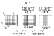
- FIG. 3 is a schematic diagram showing the calculation process of each thread in the backprojection processing according to the first embodiment of the present invention.
- each GPU thread calculates one row of data, and the data accessed simultaneously by adjacent threads is in a line and is adjacent in memory, so the threads in one warp (the smallest unit in which GPU threads are parallel) access
- the data to be processed can achieve coreless access. Since each point on one line of the image corresponds to an equally spaced point on the receiving apparatus, the projection interpolation parameter is the same and the amount of calculation is small.
- each GPU thread calculates one row of data, and the data accessed simultaneously by adjacent threads is in a line and is adjacent in memory, so the threads in one warp (the smallest unit in which GPU threads are parallel) access
- the data to be processed can achieve coreless access.
- the adjacent points on one line of the image correspond to unequally spaced points on the receiving apparatus, but since the projection interpolation parameters are the same, they can be calculated in the same way and the calculation amount is small.
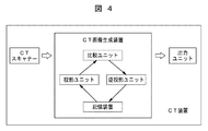
- FIG. 4 is a block diagram showing a schematic structure of a CT apparatus according to the second embodiment of the present invention.
- the CT apparatus according to the second embodiment of the present invention further includes a projection unit and a comparison unit based on the CT apparatus according to the first embodiment.
- the comparison unit, the projection unit, the storage device, and the back projection device constitute a CT image generation device.
- the storage device stores the predicted three-dimensional CT image as a plurality of mutually parallel two-dimensional CT image slides, and the second CT in each CT image slide.
- the CT image slide data is sequentially stored according to a predetermined direction (for example, a column direction).
- the projection unit uses a multi-core processor to make each thread orthogonal to the second predetermined direction (for example, the column direction) in the CT image slide with respect to the CT image slide data stored in the storage device.
- a projection image of the CT image slide is obtained, and a plurality of CT image slides are obtained.
- a projection image of the predicted three-dimensional CT image is acquired by cumulatively adding the projection images. The detailed situation of the projection processing performed by the projection unit will be described later.
- the comparison unit compares the projection image of the predicted 3D CT image acquired by the projection unit with the projection image of the scan target acquired by the CT scanner, and calculates a projection error.
- the back projection unit of the CT apparatus projects the projection error calculated by the comparison unit onto the predicted 3D CT image, corrects the predicted 3D CT image, and corrects the predicted third order corrected in the storage device.
- the original CT image replaces the original predicted 3D CT image, thereby completing a single projection-backprojection iteration process.
- the projection unit continuously performs the above-described processing on the corrected predicted three-dimensional CT image stored in the storage device, and the comparison unit and the back projection unit also By performing the above-described process, the projection-backprojection iteration process is performed again.
- the projection error satisfies a condition (for example, smaller than a predetermined threshold)
- the iterative projection-backprojection process is stopped, and the corrected predicted 3D CT image at this time is output by the output unit.
- FIG. 5 is a flowchart showing a CT image generation method according to the second embodiment of the present invention.
- step S ⁇ b> 1 the CT scanner scans the scan target with X-rays and acquires a projection image of the scan target. That is, the actual measurement projection value P measurement by an actual CT scanner is acquired.
- the storage device stores the predicted three-dimensional CT image as a plurality of parallel two-dimensional CT image slides, and data of the CT image slides according to a predetermined direction (for example, column direction) in each CT image slide.
- a predetermined direction for example, column direction
- the predicted value f of the three-dimensional CT image is initialized, and the CT data is stored as a series (N) of parallel two-dimensional CT slides (S1, S2,..., Sn).
- a projection direction that is as perpendicular to the X-ray as possible is selected as the direction of the CT slide.
- the storage method of each CT slide is stored according to the column. That is, the first column is stored first, and then the second column is stored. The same applies hereinafter.
- step 3 the projection unit sequentially processes the stored CT image slide data according to a direction in which each thread is orthogonal to a predetermined direction in the CT image slide using a multi-core processor.
- a projection image of the CT image slide is obtained, and cumulative projection addition of the projection images of a plurality of CT image slides is performed, thereby predicting three-dimensional A projection image of the CT image is acquired.
- FIG. 6 is a schematic diagram showing a projection process according to the second embodiment of the present invention. As shown in FIG. 6, the specific implementation steps of the projection unit are as follows.
- the projection unit starts the GPU kernel 1 and calculates the projection images (P1, P2,..., Pn) of all CT slides (S1, S2,..., Sn). Both the CT data Si and the projection image Pi are stored in the column direction.
- each GPU thread calculates a projection value of one row of the projection image Pi, and the row is perpendicular to the storage direction column of CT data.
- the parallel scale (that is, the number of parallel threads) of the GPU kernel is the number of projected image rows * the number of CT slides n.
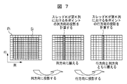
- FIG. 7 is a schematic diagram showing the calculation process of each thread in the projection processing according to the second embodiment of the present invention.
- projection is performed in the column direction by using a distance-drive method. Similar to backprojection processing, CT data accessed simultaneously by adjacent threads is adjacent on the memory, so data accessed by threads within one warp (minimum unit with parallel GPU threads) realizes coreless access Is possible. For each point on one line of the image, the projection interpolation parameters are the same and the amount of calculation is small.
- the projection is performed in the row direction using a distance-drive method. Similar to backprojection processing, data accessed simultaneously by adjacent threads are adjacent in storage, so data accessed by threads within one warp (the smallest unit in which GPU threads are parallel) realizes coreless access. It is possible. Projection interpolation parameters are related to adjacent points on one line of the image, and can be calculated in the same manner, and the amount of calculation is small.
- obtaining projection unit invokes the GPU kernel 2, the projection images (P1, P2, ⁇ ⁇ ⁇ , Pn) calculates the cumulative value of the final projected result image P sense To do.
- the storage device sequentially stores the data of the projection image according to a third predetermined direction (for example, the column direction) in the projection image.
- the projection unit cumulatively adds a plurality of projection images, using a multi-core processor, the projection value of each corresponding position in the projection image for each projection image data stored in the storage device So that a plurality of projection images are cumulatively added in parallel by multi-threads, and in the multi-threads, threads that cumulatively add projection values at adjacent positions in the third predetermined direction are adjacent to each other. .
- each of the GPU thread calculates projection values of each point of the projected image P sense, thread adjacent to process projection data in the same column.
- the value of the corresponding position of each Pi image is read to find the sum. Since the data on the projected image Pi that is simultaneously accessed by adjacent threads are adjacent in storage, the data accessed by the threads in one warp (the smallest unit in which GPU threads are parallel) can achieve coreless access. Is possible.
- step S4 the projection image of the predicted three-dimensional CT image is compared with the projection image of the scan object, and a projection error is calculated. That is, the theoretical projection value P theory and the actual measurement projection value P measurement are compared to obtain a projection error value ⁇ P.
- step S5 it is determined whether or not the projection error satisfies a condition, that is, whether or not the projection error is smaller than a predetermined threshold value. If the condition is satisfied, that is, if the projection error is smaller than the predetermined threshold, step S6 is executed. If the condition is not satisfied, that is, if the projection error is greater than or equal to a predetermined threshold, step 7 is executed.
- step S6 the output unit outputs the predicted three-dimensional CT image at this time. That is, the predicted value f at this time is output as the final CT image iterative reconstruction result.
- the backprojection unit uses a multi-core processor to project the projection error by multi-thread so that each thread sequentially processes according to a direction orthogonal to a predetermined direction (for example, column direction) in the CT image slide.
- a direction orthogonal to a predetermined direction for example, column direction
- the backprojection unit backprojects the projection error value ⁇ P onto the CT image, corrects the original predicted value f based on a certain principle, and corrects the predicted value f of the corrected CT image. To get.
- the backprojection unit starts the GPU kernel and calculates the backprojection result of the projection error value ⁇ P for all CT slides (S1, S2,..., Sn). Both the CT data Si and the projection image Pi are stored in the column direction.
- each GPU thread calculates data in one row of the CT slide Si, and the row is perpendicular to the storage direction column of CT data.
- the parallel scale (that is, the number of parallel threads) of the GPU kernel is CT slide row number * CT slide number n. Each thread is as shown in FIG.
- back projection is performed in the column direction using a distance-driving method.
- data accessed simultaneously by adjacent threads is adjacent in memory, so data accessed by threads within one warp (the minimum unit in parallel with GPU threads) realizes coreless access. Is possible.
- the projection interpolation parameter is the same and the amount of calculation is small.
- back projection is performed in the row direction using a distance-driving method.
- data accessed simultaneously by adjacent threads is adjacent in memory, so data accessed by threads within one warp (the minimum unit in parallel with GPU threads) realizes coreless access. Is possible.
- Projection interpolation parameters are related to adjacent points on one line of the image, and can be calculated in the same manner, and the amount of calculation is small.
- the one-time projection-backprojection iteration process is completed.
- the iterative process is repeated according to the process shown in FIG. 5, and the iteration is stopped when the projection error ⁇ P in Step 5 satisfies the iteration stop condition (for example, smaller than a predetermined threshold).
- the predicted value f of the image used in the last one iteration is the final CT image iteration reconstruction result.
- the parallel processing method on the GPU is shown for the projection process and the backprojection process, which are the two core steps during the iterative reconstruction.
- the iterative reconstruction process at the start of the iteration, first, an initial three-dimensional CT image is assumed, a projection operation is performed on the image, and then the projection result and the actual CT scanner result are compared. Subsequently, the comparison difference is back projected onto the CT image space, and the initial CT image is corrected and updated. In this way, one iteration is completed. If the difference between the calculated value and the actual measured value is smaller than a certain threshold value, the iteration is stopped.
- each thread processes data in a predetermined direction (for example, one row), and the data in the row is sequentially processed one by one by the thread.
- a predetermined direction for example, one row
- the data in the row is sequentially processed one by one by the thread.
- data points located in the same row are partly the same in the projection / backprojection conversion, and use the calculation result of the previous point when calculating the parameters of the next point. Therefore, when one thread processes one line and one thread processes only one point, iterative computation when processing data points on the same line is suppressed, and the calculation speed is reduced. Can be increased.
- data storage and access correspond to each other so that adjacent memory is simultaneously accessed by adjacent threads, thereby realizing coreless access to the memory by a plurality of threads.
- Speed can be increased.
- the CT slide in the present invention is stored in a certain direction (for example, the column direction)
- the CT slide data is read from the memory into the buffer memory in the column order.
- each thread processes one row, the data in the row is processed point by point by the thread, and a column of adjacent data is accessed simultaneously by the adjacent thread.
- thread 1 processes the data in the first row
- thread 2 processes the data in the second row
- thread 1 first reads and processes the points in the first column of the first row, and at the same time
- thread 2 Read the point in the first column of the row and process it.
- thread 1 reads and processes the points in the second column of the first row, and at the same time
- thread 2 The point is read and processed, and so on. Therefore, adjacent threads belonging to the minimum parallel unit simultaneously read data located in the same column, and data located in the same column other than data used during processing of the thread 1 is also in the buffer memory, and the thread 2 is transferred from the buffer memory to the column.
- Data can be directly called, it is not necessary to frequently access memory, coreless access to the memory of a plurality of threads is realized, and the memory access speed is increased.
- the technical solution of the present invention is applied to iterative reconstruction, which is a future trend in the CT image reconstruction field.
- iterative reconstruction which is a future trend in the CT image reconstruction field.
- each thread calculates the projection cumulative addition value of one projection point in the receiving apparatus, and the calculation is simple and only the calculation for obtaining the sum.
- the calculations between the threads are independent from each other, and the parallel scale is the number of points of the receiving device (that is, the size of the projection image). Since threads that process projection data in the same column are adjacent and a plurality of threads satisfy the condition of coreless access to the memory, the access speed to the memory can be improved.
- the third embodiment is an improvement based on the first embodiment and the second embodiment, and provides a specific method for storing CT image slides.
- the difference between the third embodiment, the first embodiment, and the second embodiment will be mainly described.
- the storage device stores the predicted three-dimensional CT image by various storage methods, and the directions of the planes where the CT image slide is located are different between the storage methods.
- the projection unit stores in various storage methods according to the scanning direction of the CT scanner so that the plane in which the CT image slide is located in the predicted 3D CT image in the selected storage method and the scanning direction are closest to each other. Selection is performed on the predicted three-dimensional CT image stored in the apparatus.
- FIG. 8 is a schematic diagram showing a CT data storage method according to the third embodiment of the present invention. The storage method is as shown in FIG.
- CT data is stored in the x direction, the first dimension is x, the second dimension is z, and the third dimension is y.
- the CT data is composed of a series of CT slides (S1, S2,..., Sn) parallel to the xz plane, and the number n of CT slides is the size of the third dimension y, which is called CT - x data,
- the x direction of the CT slide is referred to as a column and the z direction is referred to as a row, and the CT slide is stored in the column direction.
- CT data is stored in the y direction, the first dimension is y, the second dimension is z, and the third dimension is x.
- CT data is composed of a series of CT slides (S1, S2,..., Sn) parallel to the yz plane, and the number n of CT slides is the size of the third dimension x, which is referred to as CT - y data,
- the y direction of the CT slide is referred to as a column and the z direction is referred to as a row, and the CT slide is stored in the column direction.
- the X-ray source projects around the CT data (which is a patient during an actual CT scan) from each angle to calculate the projection result.
- the type of CT data stored in the X-ray source is determined depending on the angle where the X-ray source is located.
- FIG. 9 is a schematic diagram showing the relationship between the X-ray scan direction and the CT data storage method in the third embodiment of the present invention. The relationship is as shown in FIG.
- the radiation source is located between 315 and 45 degrees, or between 135 and 225 degrees, read the CT - x data.
- the CT - y data is read.
- the present invention is not limited to this, and various storage methods can be used.
- the more storage methods the more it is possible to select a CT slide whose direction is more perpendicular to the X-ray, but at the same time a larger storage space is required. Therefore, a suitable number of storage methods can be selected based on CT image reconstruction conditions and the performance of the CT apparatus.
- 3D CT data is stored as a series (N) of parallel 2D CT image slides, and corresponding CT data based on different projection directions.
- N the direction of the selected CT image slide is made as perpendicular as possible to the X-ray projection direction.
- the projection interpolation parameter in the calculation direction of each point on each CT image slide is the same or related, the calculation amount of the projection processing can be reduced, and the calculation speed of the iterative reconstruction can be further increased.
- the distance driving method is adopted as a specific iterative reconstruction algorithm, but the present invention is not limited to this, and the projection unit and backprojection unit of the present invention can be used for any iterative reconstruction. It can also be applied to configuration algorithms.
- the parallel method of the projection unit and backprojection unit of the present invention is not limited to a specific projection algorithm and backprojection algorithm, and is separated from the distance-driven projection algorithm described in the embodiment of the present invention. It can also be used for other projection algorithms such as a possible footprint (Separable-Footprint).
- the present invention has been described as being realized by the CT apparatus, but the present invention can also be realized by the CT image generating apparatus described in each of the above-described embodiments.
- the present invention can also be realized by the CT image generating apparatus described in each of the above-described embodiments.
- by replacing the CT scanner in the above-described CT apparatus with a CT scan projection data receiving apparatus it can also be realized as a CT scan projection data processing apparatus for receiving and processing CT scan projection data.
- each of the predetermined directions related to storage, projection, and backprojection is a row direction, but the present invention is not limited to this, and each of the predetermined directions described above is not limited thereto. Are optional and each may be the same or different.
- a GPU processor is used.
- the present invention is not limited to this, and any multi-core processor capable of parallel multi-thread processing can be used to implement the present invention. Can do.
Landscapes
- Health & Medical Sciences (AREA)
- Engineering & Computer Science (AREA)
- Life Sciences & Earth Sciences (AREA)
- Medical Informatics (AREA)
- Physics & Mathematics (AREA)
- Pathology (AREA)
- Biomedical Technology (AREA)
- Biophysics (AREA)
- High Energy & Nuclear Physics (AREA)
- Theoretical Computer Science (AREA)
- Nuclear Medicine, Radiotherapy & Molecular Imaging (AREA)
- Optics & Photonics (AREA)
- Veterinary Medicine (AREA)
- Radiology & Medical Imaging (AREA)
- Public Health (AREA)
- Heart & Thoracic Surgery (AREA)
- Molecular Biology (AREA)
- Surgery (AREA)
- Animal Behavior & Ethology (AREA)
- General Health & Medical Sciences (AREA)
- Computer Vision & Pattern Recognition (AREA)
- General Physics & Mathematics (AREA)
- Pulmonology (AREA)
- Apparatus For Radiation Diagnosis (AREA)
Abstract
処理対象物の画像において所定の方向にしたがって該画像のデータを順次記憶し、マルチコアプロセッサを利用して、それぞれのスレッドが所定の方向と直交になる方向に順次処理するように、複数のスレッドによって逆投影/投影処理を並行して行なうことで、三次元CT画像を取得して出力する。これにより、GPUなどマルチコアプロセッサを利用することで、柔軟性が高く、制限が少なく、処理速度がバンド幅に制限される技術課題を解決した。同時に、記憶及び逆投影/投影処理においてマルチコアプロセッサを利用してデータを処理する際に、GPUなどマルチコアプロセッサのマルチスレッドメモリアクセスの規則を十分に考慮して、キャッシュヒット率を向上させ、コアレスドアクセスを実現し、メモリのアクセス速度を大幅に向上させた。
Description
本発明はCT装置及びCT画像生成方法に関し、特にCT画像再構成、中でもパラレル再構成のためのCT装置及びCT画像生成方法に関する。
コンピュータトモグラフィー(CT)は医学画像分野に幅広く応用されている。コンピュータトモグラフィー(CT)は、コンピュータ技術を利用して被測定物体の断層スキャン画像に対して再構成を行って三次元断層画像を取得するスキャン方法である。該スキャン方法は、単一軸面の放射線によって被測定物体を貫通し、放射線に対する被測定物体の各部分の吸収と透過率の相違に基づいて、コンピュータにより透過放射線を収集し、三次元によって画像を再構成する。
解析的再構成と反復再構成はCT画像再構成の二つの基本方法である。フィルタ補正逆投影は解析的再構成の主なアルゴリズムであり、再構成速度が速く、現在のCT製品において幅広く応用されている。しかしながら、フィルタ補正逆投影では毎回の投影測定データが正確に定量化されて、完全なデータであることが求められている。フィルタ補正逆投影は、X線光子の統計変動に大きく影響され、ノイズとアーティファクトに対して非常に敏感である。放射線量が低下したり投影データの収集が不足したりした場合、再構成した画像の品質が良くないため、フィルタ補正逆投影を利用すると放射線量を大幅に低下させることは不可能である。
CT放射線の被ばくに対する考慮より、CT放射線量を制御し低下させるために多くのCT科学者、製造業者及び臨床スタッフが長年にわたり努力を重ねてきた。低放射線量CTは今後の傾向である。現在、多列CTの製造業者はいずれも反復再構成アルゴリズムの研究に一層力を入れており、反復再構成アルゴリズムの放射線量が、画像品質の安定を保証することを前提で、現在のフィルタ補正逆投影アルゴリズムよりも60%~80%低くなると予想されている。反復再構成は、投影と逆投影の計算を繰り返し行なう必要があり、計算量が大きく、速度が遅いため、CT製品に応用されるためには、反復再構成の処理速度を高めることが、早急に解決すべき課題になっている。
他方、近年において、画像プロセッサ(GPU)の高性能数値演算能力が迅速に発展を遂げている。NVIDIA会社が2007年に正式に発表したCUDA(Computer Unified Device Architecture、コンピュータユニファイドデバイスアーキテクチャ)は、類似C言語(従来のC言語をサポートする上で、一部を拡張した)を使用することで開発の作業がより簡単になった。GPUは図形処理に限らず、汎用数値計算にも応用され、特にパラレル度が高く数値演算量が大きい演算に適する。
特許文献1では、GPUマルチスレッドを利用してCTフィルタ逆投影再構成計算を行なう方法が開示されている。該方法は、再構成の必要があるCT画像を幾つかのブロック(Block)区域に分け、それぞれのGPUの複数のカーネルのマルチスレッドが画像の異なるブロック区域の再構成を行なうことでCT画像再構成の速度を高める。該技術はGPUクラスタのパラレル再構成システムに基づくものであり、中心ノードと計算ノードはデータを頻繁に交換する必要があり、処理速度がバンド幅に制限される。また、該技術は、再構成CT画像のブロック区域の区画に対して条件があり、該条件を満たさないとGPUメモリアドレスのコンフリクトが発生する。
上述のように、特許文献1などの従来の技術において、GPUなどパラレル度が高く数値演算量が大きい演算に適するマルチコアプロセッサをCT画像再構成に用いた場合、処理速度がバンド幅に制限されたり、メモリアドレスがコンフリクトしたりするなどの技術課題が依然として存在し、CT画像再構成においてプロセッサの演算能力を十分に生かすことができない。特に、今後の傾向である反復再構成において、反復過程における演算速度、特に並列演算速度の向上が求められるが、従来の技術では上記の条件を十分に満たすことができない。
本発明は、従来の技術におけるCT画像再構成に存在する上述の技術課題を鑑みてなされたものであり、マルチコアプロセッサを利用することによって、CT画像再構成における演算速度を高めることができ、特にCT画像再構成において反復再構成を使用した場合、反復再構成の演算速度を高めることができるCT装置及びCT画像生成方法を提供することを目的とする。
上述の技術課題を解決するために、本発明は、X線によってスキャン対象物をスキャンし、前記スキャン対象物の三次元CT画像を出力するCT装置であって、X線によってスキャン対象物をスキャンし、前記スキャン対象物の投影画像を取得するCTスキャナーと、投影画像における第1の所定の方向にしたがって該投影画像のデータを順次記憶する記憶装置と、マルチコアプロセッサを利用して、前記記憶装置に記憶されている投影画像のデータに対して、それぞれのスレッドが投影画像において前記第1の所定の方向と直交になる方向にしたがって順次処理するように、マルチスレッドによって投影画像に対して並行して逆投影を行なうことで、三次元CT画像を取得する逆投影ユニットと、前記逆投影ユニットによって取得した三次元CT画像を出力する出力ユニットと、を備えることを特徴とする。
本発明に係るCT装置によれば、GPUなどマルチコアプロセッサを利用することで、柔軟性が高く、制限が少なく、従来の技術におけるGPUクラスタを必要とせずに並列計算を実現することが可能であり、従来の技術において処理速度がバンド幅に制限される技術課題を解決した。また、記憶装置にデータを記憶したり、逆投影ユニットがマルチコアプロセッサを利用してデータを処理したりする際に、GPUなどマルチコアプロセッサのマルチスレッドメモリアクセスの規則を十分に考慮して、キャッシュヒット率を向上させ、コアレスドアクセスを実現し、メモリのアクセス速度を大幅に向上させることができる。これにより、CT画像再構成においてプロセッサの演算能力を十分に生かし、CT画像再構成の演算速度を大幅に向上させることができる。
本発明によるCT装置において、前記記憶装置は、予測三次元CT画像を複数の互いに平行する二次元のCT画像スライドとして記憶し、それぞれのCT画像スライドにおける第2の所定の方向にしたがって該CT画像スライドのデータを順次記憶し、前記CT装置は、マルチコアプロセッサを利用して、前記記憶装置に記憶されているCT画像スライドのデータに対して、それぞれのスレッドがCT画像スライドにおいて前記第2の所定の方向と直交になる方向にしたがって順次処理するように、マルチスレッドによって該CT画像スライドに対して並行して投影を行なうことで、該CT画像スライドの投影画像を取得し、複数のCT画像スライドの投影画像を累積加算することで、予測三次元CT画像の投影画像を取得する投影ユニットと、前記投影ユニットによって取得した予測三次元CT画像の投影画像と前記CTスキャナーによって取得した前記スキャン対象物の投影画像とを比較して投影誤差を計算する比較ユニットと、をさらに備え、前記CT装置において、前記逆投影ユニットは、前記投影誤差を予測三次元CT画像に逆投影するとともに、予測三次元CT画像に対して修正を行い、修正された予測三次元CT画像で元の予測三次元CT画像を代替し、これにより一回の投影-逆投影の反復処理が完成し、前記投影誤差が所定の閾値よりも小さくなるまでに、前記投影-逆投影の反復処理を少なくとも一回行い、前記出力ユニットは、前記投影誤差が所定の閾値よりも小さくなったときの修正後の予測三次元CT画像を出力してもよい。
上述のCT装置によれば、本発明の技術案をCT画像再構成分野における今後の傾向である反復再構成に適用する。具体的には、反復再構成における二つのコア内容は投影処理と逆投影処理であり、投影処理と逆投影処理が反復再構成において大部分の処理時間を占める。上述のCT装置により、投影処理と逆投影処理においてそれぞれGPUなどマルチコアプロセッサのマルチスレッドメモリアクセスの規則を考慮し、マルチコアプロセッサを利用して並列処理を実現することで、反復再構成の演算速度を大幅に向上させ、反復再構成の低放射線量CT製品への応用を可能にした。
本発明によるCT装置において、前記記憶装置はさらに、前記CT画像スライドの投影画像における第3の所定の方向にしたがって該CT画像スライドの投影画像のデータを順次記憶し、前記投影ユニットが複数のCT画像スライドの投影画像を累積加算する際に、マルチコアプロセッサを利用して、前記記憶装置に記憶されているCT画像スライドの投影画像のデータに対して、それぞれのスレッドが前記複数のCT画像スライドの投影画像におけるそれぞれの対応位置の投影値を累積加算するように、マルチスレッドによって複数のCT画像スライドの投影画像を並行して累積加算し、該マルチスレッドにおいて、前記第3の所定の方向上の隣接する位置の投影値を累積加算するスレッドが互いに隣接してもよい。
上述のCT装置によれば、投影処理において複数のCT画像スライドの投影画像を累積加算する際に、マルチコアプロセッサを利用することで、それぞれのスレッドが受信装置内の一つの投影ポイントの投影累積値を計算し、その計算は簡単で、和を求める演算のみである。それぞれのスレッド間の計算は互いに独立し、並列規模は受信装置のポイントの数つまり投影画像の大きさである。同一列の投影データを処理するスレッドが隣接し、複数のスレッドがメモリにコアレスドアクセスする条件を同様に満足するため、メモリアクセス速度をさらに向上させ、投影処理及び反復再構成の演算速度を高めることができる。
本発明によるCT装置において、前記記憶装置は、予測三次元CT画像を様々な記憶方法で記憶し、それぞれの記憶方法の間において、前記CT画像スライドの所在する平面の方向が互いに異なり、前記投影ユニットは、選択された記憶方法での予測三次元CT画像におけるCT画像スライドの所在する平面と前記スキャン方向とが最も垂直に近いように、前記CTスキャナーのスキャン方向に基づいて、様々な記憶方法で前記記憶装置に記憶されている予測三次元CT画像に対して選択を行なってもよい。
上述のCT装置によれば、データの記憶については、三次元CTデータを一連(N個)の平行する二次元CT画像スライドとして記憶し、異なる投影方向に基づいて対応するCTデータ記憶方法を選択することにより、選択されたCT画像スライドの方向をできる限りX線の投影方向に垂直になるようにする。これにより、各CT画像スライド上の各ポイントの演算方向における投影補間パラメータが同じであるかまたは関連し、投影処理の計算量を減らし、反復再構成の演算速度をさらに高めることができる。
本発明によるCT装置において、前記逆投影ユニットは、距離駆動方法を使用して、それぞれ第1の所定の方向と該第1の所定の方向と直交になる方向に沿って逆投影を行ない、及び/または前記投影ユニットは、距離駆動方法を使用して、それぞれ第2の所定の方向と該第2の所定の方向と直交になる方向に沿って投影を行なってもよい。
上述のCT装置によれば、本発明の技術案を反復再構成の主な実現方法の一つである距離駆動方法に具体的に適用する。これにより、本発明のCT装置の反復再構成の実用性をさらに向上させる。
本発明によるCT装置において、前記マルチコアプロセッサが記憶装置にアクセスする際に、前記マルチコアプロセッサにおける近いスレッドが前記記憶装置において記憶位置の近いデータをコアレスドアクセス可能であってもよい。
上述のCT装置によれば、利用されるマルチコアプロセッサの記憶装置(メモリ)アクセス規則は、マルチコアプロセッサにおける近いスレッドが前記記憶装置において記憶位置の近いデータをコアレスドアクセスすることができる。したがって、本発明の記憶装置のデータ記憶方法とプロセッサの並列処理方法とを採用することで、キャッシュヒット率を向上させ、コアレスドアクセスを実現し、メモリのアクセス速度を大幅に向上させることができる。これにより、CT画像再構成においてプロセッサの演算能力を十分に生かし、CT画像再構成の演算速度を大幅に向上させることができる。
本発明によるCT装置において、前記マルチコアプロセッサはGPU、すなわち画像処理装置であってもよい。
上述のCT装置によれば、マルチコアプロセッサとしてGPU、すなわち画像処理装置を採用する。GPUがその他のプロセッサに対してはコア(core)の数が多く、同時処理可能なスレッド数が多いため、本発明の上述の利点をさらに生かすことができる。
上述の技術課題を解決するために、本発明はさらに、X線によってスキャン対象物をスキャンし、前記スキャン対象物の三次元CT画像を生成するCT画像生成方法であって、X線によってスキャン対象物をスキャンし、前記スキャン対象物の投影画像を取得するステップと、予測三次元CT画像を複数の互いに平行する二次元のCT画像スライドとして記憶し、それぞれのCT画像スライドにおける所定の方向にしたがって該CT画像スライドのデータを順次記憶するステップと、マルチコアプロセッサを利用して、記憶されているCT画像スライドのデータに対して、それぞれのスレッドがCT画像スライドにおいて前記所定の方向と直交になる方向にしたがって順次処理するように、マルチスレッドによって該CT画像スライドに対して並行して投影を行なうことで、該CT画像スライドの投影画像を取得し、複数のCT画像スライドの投影画像を累積加算することで、予測三次元CT画像の投影画像を取得するステップと、予測三次元CT画像の投影画像と前記スキャン対象物の投影画像とを比較して投影誤差を計算するステップと、マルチコアプロセッサを利用して、それぞれのスレッドがCT画像スライドにおいて前記所定の方向と直交になる方向にしたがって順次処理するように、マルチスレッドによって前記投影誤差を予測三次元CT画像に並行して逆投影するとともに、予測三次元CT画像に対して修正を行い、修正された予測三次元CT画像で元の予測三次元CT画像を代替し、これにより一回の投影-逆投影の反復処理が完成し、前記投影誤差が所定の閾値よりも小さくなるまでに、前記投影-逆投影の反復処理を少なくとも一回行なうステップと、前記投影誤差が所定の閾値よりも小さくなったときの修正後の予測三次元CT画像を出力するステップと、を含むことを特徴とする。
本発明に係るCT画像生成方法によれば、GPUなどマルチコアプロセッサを利用することで、柔軟性が高く、制限が少なく、従来の技術におけるGPUクラスタを必要とせずに並列計算を実現することが可能であり、従来の技術において処理速度がバンド幅に制限される技術課題を解決した。同時に、記憶装置にデータを記憶したり、逆投影ユニットがマルチコアプロセッサを利用してデータを処理したりする際に、GPUなどマルチコアプロセッサのマルチスレッドメモリアクセスの規則を十分に考慮して、キャッシュヒット率を向上させ、コアレスドアクセスを実現し、メモリのアクセス速度を大幅に向上させた。これにより、CT画像再構成においてプロセッサの演算能力を十分に生かし、CT画像再構成の演算速度を大幅に向上することができた。特に、CT画像再構成分野において今後の傾向である反復再構成に適用することで、投影処理と逆投影処理においてそれぞれGPUなどマルチコアプロセッサのマルチスレッドメモリアクセスの規則を考慮し、マルチコアプロセッサを利用して並列処理を実現することで、反復再構成の演算速度を大幅に向上させ、反復再構成の低放射線量CT製品への応用を可能にした。
以下、図面に基づいて本発明のそれぞれの実施形態について説明する。それぞれの実施形態は、本発明の最適な形態の実現について説明するだけのものであって、本発明を限定するものではない。
まず、本発明の第1の実施形態について説明する。図1は本発明の第1の実施形態に係わるCT装置の概略構造を示すブロック図である。図1に示すように、第1の実施形態に係わるCT装置は、X線によってスキャン対象物をスキャンし、スキャン対象物の三次元CT画像を出力し、CTスキャナー、記憶装置、逆投影ユニット及び出力ユニットを備える。そのうち、記憶装置と逆投影ユニットはCT画像生成装置を構成する。以下、CT装置の各構造について詳しく説明する。
CTスキャナーは、X線によってスキャン対象物をスキャンし、スキャン対象物の投影画像を取得する。具体的には、単一軸面の放射線によってスキャン対象物を貫通し、X線に対するスキャン対象物の各部分の吸収と透過率の相違により、スキャン対象物の投影画像を取得する。
記憶装置は投影画像における第1の所定の方向にしたがって該投影画像のデータを順次記憶する。該記憶装置はメモリなどのような記憶装置によって実現される。投影画像は例えば二次元画像であり、その中のデータが第1の所定の方向(例えば列方向)にしたがって記憶装置に順次記憶される。すなわち、先に一列目を記憶し、その後二列目を記憶し、以下同様である。
逆投影ユニットは、マルチコアプロセッサを利用して、記憶装置に記憶されている投影画像のデータに対して、それぞれのスレッドが投影画像において第1の所定の方向と直交になる方向にしたがって順次処理するように、マルチスレッドによって投影画像に対して並行して逆投影を行なうことで、三次元CT画像を取得する。マルチコアプロセッサは、例えばGPU(画像処理装置)であり、現在よく利用されているGPUとして、何百個のコア(core)を有し、複数のコアによってマルチスレッド並列処理を実現する。ここでは、マルチコアプロセッサがマルチスレッドによって投影画像に対して並行して逆投影を行なう。そのうち、マルチスレッドにおける各スレッドがそれぞれ投影画像において第1の所定の方向(例えば列方向)と直交になる方向(例えば行方向)にしたがって順次処理する。逆投影ユニットによって行われる逆投影処理については後で説明する。
出力ユニットは、逆投影ユニットによって取得した三次元CT画像を出力する。ここで、出力ユニットは、例えばCT画像表示装置であり、液晶ディスプレイまたはタッチパネルなどのディスプレイ装置によって実現し、生成された三次元CT画像を表示する。また、出力ユニットは、生成された三次元CT画像をプリントアウトする印刷装置などであってもよい。もちろん、出力ユニットは、生成された三次元CT画像を出力可能でさえあればよく、汎用のI/Oインターフェースであってもよい。
続いて、本発明の第1の実施形態の逆投影処理について詳しく説明する。図2は本発明の第1の実施形態に係わる逆投影処理を示す略図である。図2に示すように、具体的な逆投影処理は以下の説明のとおりである。
逆投影ユニットはGPUカーネル(Kernel)を起動して、記憶装置によって記憶されている投影画像のCTスライド(S1、S2、…、Sn)上の逆投影結果を計算する。記憶装置において、CTスキャナーによって取得した投影画像データは、例えば図中の列方向に沿って記憶される。逆投影結果である三次元CTデータにおいて、CTデータSiは同じく図中の列方向に沿って記憶される。逆投影プロセスにおいて生成された投影画像Piにおいて、データは同じく図中の列方向に沿って記憶される。GPUスレッドの並列方法はそれぞれのGPUスレッドがCTスライドSiにおける一行のデータを計算し、該行はCTデータの記憶方向列と垂直になる。該GPUカーネルの並列規模(すなわち並列スレッド数)は、CTスライド行数*CTスライド数nである。
以下、図3に基づいてそれぞれのスレッドの演算プロセスについて説明する。図3は本発明の第1の実施形態に係わる逆投影処理においてそれぞれのスレッドの演算プロセスを示す略図である。
図3に示すように、まず、距離駆動(Distance-Driven)の方法を用いて列方向に逆投影する。それぞれのGPUスレッドが一行のデータを計算し、隣接スレッドが同時にアクセスするデータは一列にあり、記憶上で隣接しているため、一つのwarp(GPUスレッドが並列する最小単位)内のスレッドがアクセスするデータはコアレスドアクセスを実現することが可能である。画像の一列上のそれぞれのポイントに対しては、受信装置上の等間隔のポイントに対応するため、投影補間パラメータが同じであり、計算量が少ない。
そして、距離駆動(Distance-Driven)の方法を用いて行方向に逆投影する。それぞれのGPUスレッドが一行のデータを計算し、隣接スレッドが同時にアクセスするデータが一列にあり、記憶上で隣接しているため、一つのwarp(GPUスレッドが並列する最小単位)内のスレッドがアクセスするデータはコアレスドアクセスを実現することが可能である。画像の一行上の隣接ポイントに対しては、受信装置上の不等間隔のポイントに対応するが、投影補間パラメータが同じであるため、同様に計算することができ、計算量が少ない。
本発明の第1の実施形態に係わるCT装置により、GPUなどマルチコアプロセッサを利用することで、柔軟性が高く、制限が少なく、従来の技術におけるGPUクラスタを必要とせずに並列計算を実現することが可能であり、従来の技術において処理速度がバンド幅に制限される技術課題を解決した。同時に、記憶装置にデータを記憶したり、逆投影ユニットがマルチコアプロセッサを利用してデータを処理したりする際に、GPUなどマルチコアプロセッサのマルチスレッドメモリアクセスの規則を十分に考慮して、キャッシュヒット率を向上させ、コアレスドアクセスを実現し、メモリのアクセス速度を大幅に向上させた。これにより、CT画像再構成においてプロセッサの演算能力を十分に生かし、CT画像再構成の演算速度を大幅に向上することができる。
続いて、本発明の第2の実施形態について説明する。第2の実施形態と第1の実施形態の異なる点は、本発明の技術案をCT画像再構成分野の反復再構成に適用したことである。以下、第2の実施形態と第1の実施形態の異なる点を中心にして説明をする。
図4は本発明の第2の実施形態に係わるCT装置の概略構造を示すブロック図である。図4に示すように、本発明の第2の実施形態のCT装置は、第1の実施形態のCT装置を基に、さらに投影ユニットと比較ユニットとを備える。そのうち、比較ユニット、投影ユニット、記憶装置及び逆投影装置はCT画像生成装置を構成する。
具体的には、第2の実施形態に係わるCT装置において、記憶装置は、予測した三次元CT画像を複数の互いに平行する二次元CT画像スライドとして記憶し、それぞれのCT画像スライドにおける第2の所定の方向(例えば列方向)にしたがって該CT画像スライドのデータを順次記憶する。
投影ユニットは、マルチコアプロセッサを利用して、記憶装置に記憶されているCT画像スライドのデータに対して、それぞれのスレッドがCT画像スライドにおいて第2の所定の方向(例えば列方向)と直交になる方向(例えば行方向)にしたがって順次処理するように、マルチスレッドによって該CT画像スライドに対して並行して投影を行なうことで、該CT画像スライドの投影画像を取得し、複数のCT画像スライドの投影画像を累積加算することで、予測三次元CT画像の投影画像を取得する。投影ユニットによって行われる投影処理の詳しい状況については後で説明する。
比較ユニットは、投影ユニットによって取得した予測三次元CT画像の投影画像とCTスキャナーによって取得したスキャン対象物の投影画像とを比較して投影誤差を計算する。
続いて、CT装置の逆投影ユニットは、比較ユニットによって計算された投影誤差を予測三次元CT画像に投影するとともに、予測三次元CT画像に対して修正を行い、記憶装置において修正された予測三次元CT画像で元の予測三次元CT画像を代替し、これにより一回の投影-逆投影の反復処理が完成する。
続いて、投影誤差が条件を満たさない場合、投影ユニットは、記憶装置に記憶されている修正後の予測三次元CT画像に対して上述の処理を継続して行い、比較ユニットと逆投影ユニットも上述の処理を行なうことで、投影-逆投影の反復処理を再度行なう。投影誤差が条件(例えば所定の閾値よりも小さい)を満たした場合、投影-逆投影の反復処理を停止し、出力ユニットによってこのときの修正後の予測三次元CT画像を出力する。
以下、本発明の第2の実施形態に係わるCT画像生成方法について説明する。図5は本発明の第2の実施形態に係わるCT画像生成方法を示すフローチャートである。
図5に示すように、ステップS1において、CTスキャナーはX線によってスキャン対象物をスキャンし、前記スキャン対象物の投影画像を取得する。すなわち、実際のCTスキャナーによる実測投影値P測を取得する。
ステップS2において、記憶装置は、予測三次元CT画像を複数の互いに平行する二次元CT画像スライドとして記憶し、それぞれのCT画像スライドにおける所定の方向(例えば列方向)にしたがって該CT画像スライドのデータを順次記憶する。具体的には、三次元CT画像の予測値fを初期化し、該CTデータを一連(N個)の平行する二次元CTスライド(S1、S2、・・・、Sn)として記憶する。そのうち、CTスライドの方向はできる限りX線と垂直になる投影方向を選択する。それぞれのCTスライドの記憶方法は列にしたがって記憶する。すなわち、先に一列目を記憶してから二列目を記憶する。以下同様である。
ステップ3において、投影ユニットは、マルチコアプロセッサを利用して、記憶されているCT画像スライドのデータに対して、それぞれのスレッドがCT画像スライドにおいて所定の方向と直交になる方向にしたがって順次処理するように、マルチスレッドによって該CT画像スライドに対して並行して投影を行なうことで、該CT画像スライドの投影画像を取得し、複数のCT画像スライドの投影画像を累積加算することで、予測三次元CT画像の投影画像を取得する。
具体的には、投影ユニットがCT画像の予測値fに対して理論投影計算を行ない、理論投影値P理を取得する。図6は本発明の第2の実施形態に係わる投影処理を示す略図である。図6に示すように、投影ユニットの具体的な実施ステップは以下のとおりである。
(1)投影ユニットはGPUカーネル1を起動して、すべてのCTスライド(S1、S2、・・・、Sn)の投影画像(P1、P2、…、Pn)を計算する。CTデータSi及び投影画像Piはともに列方向に記憶される。GPUスレッドの並行方法は、それぞれのGPUスレッドが投影画像Piの一行の投影値を計算し、該行はCTデータの記憶方向列と垂直になる。該GPUカーネルの並列規模(すなわち並列スレッド数)は投影画像行数*CTスライド数nである。
以下、図7に基づいてそれぞれのスレッドの演算プロセスについて説明する。図7は本発明の第2の実施形態に係わる投影処理においてそれぞれのスレッドの演算プロセスを示す略図である。
図7に示すように、まず、距離駆動(Distance-Driven)の方法を用いて列方向に投影する。逆投影処理と同様に、隣接スレッドが同時にアクセスするCTデータは記憶上で隣接しているため、一つのwarp(GPUスレッドが並行する最小単位)内のスレッドがアクセスするデータはコアレスドアクセスを実現することが可能である。画像の一列上のそれぞれのポイントに対しては、投影補間パラメータが同じであり、計算量が少ない。
続いて、距離駆動(Distance-Driven)の方法を用いて行方向に投影する。逆投影処理と同様に、隣接スレッドが同時アクセスするデータは記憶上で隣接しているため、一つのwarp(GPUスレッドが並行する最小単位)内のスレッドがアクセスするデータはコアレスドアクセスを実現することが可能である。画像の一行上の隣接ポイントに対しては、投影補間パラメータが関連し、同様に計算することができ、計算量が少ない。
(2)図6に戻り、投影ユニットはGPUカーネル2を起動して、投影画像(P1、P2、・・・、Pn)の累積加算値を計算し、最終的な投影結果画像P理を取得する。このとき、記憶装置は投影画像における第3の所定の方向(例えば列方向)にしたがって該投影画像のデータを順次記憶する。投影ユニットが複数の投影画像を累積加算する際に、マルチコアプロセッサを利用して、記憶装置に記憶されている投影画像のデータに対して、それぞれのスレッドが投影画像におけるそれぞれの対応位置の投影値を累積加算するように、マルチスレッドによって複数の投影画像を並行して累積加算し、該マルチスレッドにおいて、第3の所定の方向上の隣接する位置の投影値を累積加算するスレッドは互いに隣接する。
具体的には、GPUスレッドの並行方法は、それぞれのGPUスレッドが投影画像P理の各ポイントの投影値を計算し、同一列の投影データを処理するスレッドは隣接する。該GPUカーネルの並列規模(すなわち並行スレッド数)は、投影画像大きさ=列数*行数である。それぞれのスレッドに対してそれぞれのPi画像の対応位置の値を読み取って和を求める。隣接スレッドが同時にアクセスする投影画像Pi上のデータが記憶上で隣接しているため、一つのwarp(GPUスレッドが並行する最小単位)内のスレッドがアクセスするデータはコアレスドアクセスを実現することが可能である。
図5に戻って引き続き説明する。ステップS4において、予測三次元CT画像の投影画像とスキャン対象物の投影画像とを比較し、投影誤差を計算する。すなわち、理論投影値P理と実測投影値P測とを比較し、投影誤差値△Pを取得する。
ステップS5において、投影誤差が条件を満たすか否か、すなわち投影誤差が所定の閾値よりも小さいか否かを判定する。条件を満たしている場合、すなわち投影誤差が所定の閾値よりも小さい場合は、ステップS6を実行する。条件を満たしていない場合、すなわち投影誤差が所定の閾値以上である場合は、ステップ7を実行する。
ステップS6において、出力ユニットはこの時の予測三次元CT画像を出力する。すなわち、この時の予測値fが最終的なCT画像反復再構成結果として出力される。
ステップS7において、逆投影ユニットは、マルチコアプロセッサを利用して、それぞれのスレッドがCT画像スライドにおいて所定の方向(例えば列方向)と直交になる方向にしたがって順次処理するように、マルチスレッドによって投影誤差を予測三次元CT画像に並行して逆投影するとともに、予測三次元CT画像に対して修正を行い、修正された予測三次元CT画像で元の予測三次元CT画像を代替する。具体的には、逆投影ユニットは投影誤差値△PをCT画像に逆投影するとともに、一定の原則に基づいて元の予測値fに対して修正を行い、修正されたCT画像の予測値fを取得する。
逆投影ユニットの具体的な実施ステップは第1の実施形態における逆投影処理に類似しており、図2と図3に基づいて説明する。
まず、逆投影ユニットは、GPUカーネルを起動して、すべてのCTスライド(S1、S2、・・・、Sn)に対する投影誤差値△Pの逆投影結果を計算する。CTデータSi及び投影画像Piはともに列方向に記憶される。GPUスレッドの並行方法は、それぞれのGPUスレッドがCTスライドSiの一行内のデータを計算し、該行はCTデータの記憶方向列と垂直になる。該GPUカーネルの並列規模(すなわち並列スレッド数)は、CTスライド行数*CTスライド数nである。それぞれのスレッドについては図3に示すとおりである。
まず、距離駆動(Distance-Driven)の方法を用いて列方向に逆投影する。第1の実施形態と同様に、隣接スレッドが同時にアクセスするデータが記憶上で隣接しているため、一つのwarp(GPUスレッド並行の最小単位)内のスレッドがアクセスするデータはコアレスドアクセスを実現することが可能である。画像の一列上の各ポイントに対しては、投影補間パラメータが同じであり、計算量が少ない。
続いて、距離駆動(Distance-Driven)の方法を用いて行方向に逆投影する。第1の実施形態と同様に、隣接スレッドが同時にアクセスするデータは記憶上で隣接しているため、一つのwarp(GPUスレッド並行の最小単位)内のスレッドがアクセスするデータはコアレスドアクセスを実現することが可能である。画像の一行上の隣接ポイントに対しては、投影補間パラメータが関連し、同様に計算することができ、計算量が少ない。
ステップS2~S4、S7を通じて、一回の投影-逆投影の反復処理が完成する。図5に示すプロセスにより反復処理を繰り返し行ない、ステップ5における投影誤差△Pが反復中止条件(例えば所定の閾値よりも小さい)を満たした場合に反復を中止する。最後一回の反復に使用された画像の予測値fが最終的なCT画像反復再構成結果になる。
第2の実施形態では、反復再構成中の二つのコアステップである投影処理と逆投影処理に対して、GPU上の並行処理方法が示された。反復再構成のプロセスは、反復開始時に、まずは初期三次元CT画像を一つ仮定して、それに対して投影演算を行い、その後投影結果と実際のCTスキャナー結果とを比較する。続いて、比較差異をCT画像空間に逆投影し、初期CT画像に対して修正更新を行なう。このようにして一回の反復が完成する。計算値と実際測定値との差がある閾値よりも小さい場合は、反復を中止する。CT画像の反復再構成は、反復によって投影と逆投影の計算をすることで実現するため、投影と逆投影の計算が反復再構成の大部分の処理時間を占める。投影プロセスと逆投影プロセスに対してそれぞれ並列計算が完成すると、反復再構成の並行計算を実現したことになる。
また、上述の投影処理と逆投影処理においては、それぞれのスレッドが所定の方向(例えば一行)のデータを処理し、該行内のデータは該スレッドによってデータポイントが一つずつ順次処理される。このような処理には二つの利点がある。
一つ目は、同一行に位置するデータポイントは、投影/逆投影の変換において一部の計算は同じであり、次のポイントのパラメータを計算するときに前のポイントの計算結果を利用することができるため、一つのスレッドが一行を処理することと一つのスレッドが一つのポイントのみを処理することとを比べると、同一行のデータポイントを処理するときの反復計算が抑えられて、計算速度を高めることができる。
二つ目は、本発明において、隣接メモリが隣接スレッドに同時にアクセスされるように、データ記憶とアクセスが互いに対応し、これにより複数のスレッドによるメモリへのコアレスドアクセスを実現し、メモリアクセスの速度を高めることができる。具体的には、本発明におけるCTスライドがある方向(例えば列方向)に記憶されているため、CTスライドデータは列順に、メモリからバッファメモリに読み込まれる。投影と逆投影処理においては、それぞれのスレッドが一行を処理し、該行のデータは該スレッドによって一ポイントずつ処理され、一列の隣接データが隣接スレッドによって同時にアクセスされる。例えば、スレッド1は一行目のデータを処理し、スレッド2は二行目のデータを処理し、スレッド1はまず一行目の第一列のポイントを読み取って処理し、これと同時にスレッド2は二行目の第一列のポイントを読み取って処理する。最少並列単位に属するすべてのスレッドが第一列のポイントを処理した後に、スレッド1が一行目の第二列のポイントを読み取って処理し、これと同時にスレッド2が二行目の第二列のポイントを読み取って処理し、以下同様である。したがって、最少並列単位に属する隣接スレッドは同一列に位置するデータを同時に読み取り、スレッド1の処理時に使用するデータ以外の同一列に位置するデータもバッファメモリにあり、スレッド2はバッファメモリから該列データを直接呼び出すことができ、メモリアクセスを頻繁に行なう必要がなく、複数のスレッドのメモリへのコアレスドアクセスを実現し、メモリアクセス速度を高める。
本発明の第2の実施形態により、本発明の技術案をCT画像再構成分野における今後の傾向である反復再構成に適用する。投影処理と逆投影処理においてそれぞれGPUなどマルチコアプロセッサのマルチスレッドメモリアクセスの規則を考慮し、マルチコアプロセッサを利用して並列処理を実現することにより、反復再構成の演算速度を大幅に向上させ、反復再構成の低線量CT製品への応用を可能にした。
また、第2の実施形態では、投影処理の累積加算の演算において、それぞれのスレッドが受信装置内の一つの投影ポイントの投影累積加算値を計算し、その計算は簡単で、和を求める演算のみであり、それぞれのスレッド間の計算は互いに独立し、並列規模は受信装置のポイントの数(つまり投影画像の大きさ)である。同一列の投影データを処理するスレッドが隣接し、複数のスレッドがメモリにコアレスドアクセスする条件を同様に満足するため、メモリへのアクセス速度を向上させることができる。
続いて、本発明の第3の実施形態について説明する。第3の実施形態は、第1の実施形態と第2の実施形態を基に改善されたものであり、CT画像スライドの具体的な記憶方法を提供する。以下、第3の実施形態と第1の実施形態及び第2の実施形態との相違点を中心に説明する。
本発明の第3の実施形態において、記憶装置は、予測三次元CT画像を様々な記憶方法で記憶し、それぞれの記憶方法の間において、CT画像スライドの所在する平面の方向が互いに異なる。投影ユニットは、選択された記憶方法での予測三次元CT画像におけるCT画像スライドの所在する平面とスキャン方向とが最も垂直に近いように、CTスキャナーのスキャン方向にしたがって、様々な記憶方法で記憶装置に記憶されている予測三次元CT画像に対して選択を行なう。
以下、第2の実施形態を基に本実施形態に係わる様々な記憶方法の例について具体的に説明する。ここでは、図5に基づいて説明する。第3の実施形態と第2の実施形態との相違点は図5のプロセスにおけるステップS2、S3である。
第3の実施形態の図5のステップS2に対応するステップにおいて、三次元CT画像の予測値fを初期化し、CTデータを二つの方法で記憶する。図8は本発明の第3の実施形態におけるCTデータの記憶方法を示す略図である。その記憶方法については図8に示すとおりである。
方法1:CTデータはx方向に記憶され、第1次元はx、第2次元はz、第3次元はyである。CTデータはxz平面に平行する一連のCTスライド(S1、S2、…、Sn)から構成され、CTスライドの数nは第3次元yの大きさであり、これをCT-xデータと称し、CTスライドのx方向を列、z方向を行と称し、CTスライドは列方向に記憶される。
方法2:CTデータはy方向に記憶され、第1次元はy、第2次元はz、第3次元はxである。CTデータはyz平面に平行する一連のCTスライド(S1、S2、…、Sn)から構成され、CTスライドの数nは第3次元xの大きさであり、これをCT-yデータと称し、CTスライドのy方向を列、z方向を行と称し、CTスライドは列方向に記憶される。
第3の実施形態の図5のステップS3に対応するステップにおいて、X線ソースはCTデータ(実際のCTスキャン時には患者である)の周りをそれぞれの角度から投影して投影結果を計算する。X線ソースの所在するそれぞれの角度については、X線ソースの所在角度によってどの種類に記憶されているCTデータを読み取るかを決定する。図9は本発明の第3の実施形態におけるX線スキャン方向とCTデータ記憶方法との間の関係を示す略図である。その関係については図9に示すとおりである。
放射線ソースが315度~45度の間、または135度~225度の間に位置する場合は、CT-xデータを読み取る。
放射線ソースが45度~135度の間、または225度~315度の間に位置する場合は、CT-yデータを読み取る。
これにより、CTスライドの方向はできる限りX線に垂直になる投影方向を選択することを保証する。
また、その他の処理ついては第2の実施形態と同じあり、ここでは説明を省略する。
以上では、二つの記憶方法を用いた例について説明したが、本発明はこれに限定されるものではなく、様々な記憶方法を用いることもできる。記憶方法が多いほど、方向がX線にもっと垂直になるCTスライドを選択することが可能であるが、同時により大きい記憶空間も必要である。したがって、CT画像再構成の条件とCT装置の性能に基づいて好適な記憶方法の数を選択することができる。
以上では、本実施形態の様々な記憶方法を第2の実施形態に用いる例について説明したが、本実施形態の様々な記憶方法を第1の実施形態にも用いられることは明らかである。
本発明の第3の実施形態によると、データの記憶に対して、三次元CTデータを一連(N個)の平行する二次元CT画像スライドとして記憶し、異なる投影方向に基づいて対応するCTデータ記憶方法を選択することにより、選択されたCT画像スライドの方向をできる限りX線の投影方向に垂直になるようにする。これにより、各CT画像スライド上の各ポイントの演算方向における投影補間パラメータが同じであるかまたは関連し、投影処理の計算量を減らし、反復再構成の演算速度をさらに高めることができる。
以上、本発明のいくつかの具体的な実施形態について説明したが、本発明は上述の実施形態に限定されるものではなく、本発明の発明趣旨の範囲内でさらに様々な変更、または実施形態に対する組み合わせを行なうことも可能である。
例えば、第2の実施形態では、具体的な反復再構成アルゴリズムとして距離駆動方法を採用したが、本発明はこれに限定されるものではなく、本発明の投影ユニットと逆投影ユニットは如何なる反復再構成アルゴリズムにも適用可能である。本発明の投影ユニットと逆投影ユニットの並列方法も具体的な投影アルゴリズムと逆投影アルゴリズムに限定されず、本発明の実施形態に記載された距離駆動(Distance-Driven)投影アルゴリズムの外に、分離可能なフットプリント(Separable-Footprint)などのその他の投影アルゴリズムにも用いることができる。
例えば、上述の各実施形態では、CT装置によって本発明を実現することについて説明したが、本発明は上述の各実施形態において説明したCT画像生成装置によっても実現することができる。同時に、上述のCT装置におけるCTスキャナーをCTスキャン投影データ受信装置で代替することで、CTスキャン投影データを受信して処理するCTスキャン投影データ処理装置としても実現することができる。
例えば、上述の各実施形態では、記憶、投影及び逆投影に係わるそれぞれの所定の方向がいずれも列方向であるが、本発明はこれに限定されるものではなく、上述のそれぞれの所定の方向は任意選択可能であり、それぞれが同じであってもよく、異なってもよい。
例えば、上述の各実施形態では、GPUプロセッサを利用したが、本発明はこれに限定されるものではなく、並列マルチスレッド処理が可能なマルチコアプロセッサであれば、いずれも本発明の実現に用いることができる。
Claims (8)
- X線によってスキャン対象物をスキャンし、前記スキャン対象物の三次元CT画像を出力するCT装置であって、
X線によってスキャン対象物をスキャンし、前記スキャン対象物の投影画像を取得するCTスキャナーと、
投影画像における第1の所定の方向にしたがって該投影画像のデータを順次記憶する記憶装置と、
マルチコアプロセッサを利用して、前記記憶装置に記憶されている投影画像のデータに対して、それぞれのスレッドが投影画像において前記第1の所定の方向と直交になる方向にしたがって順次処理するように、マルチスレッドによって投影画像に対して並行して逆投影を行なうことで、三次元CT画像を取得する逆投影ユニットと、
前記逆投影ユニットによって取得した三次元CT画像を出力する出力ユニットと、を備えることを特徴とするCT装置。 - 前記記憶装置は、予測三次元CT画像を複数の互いに平行する二次元CT画像スライドとして記憶し、それぞれのCT画像スライドにおける第2の所定の方向にしたがって該CT画像スライドのデータを順次記憶し、
前記CT装置は、
マルチコアプロセッサを利用して、前記記憶装置に記憶されているCT画像スライドのデータに対して、それぞれのスレッドがCT画像スライドにおいて前記第2の所定の方向と直交になる方向にしたがって順次処理するように、マルチスレッドによって該CT画像スライドに対して並行して投影を行なうことで、該CT画像スライドの投影画像を取得し、複数のCT画像スライドの投影画像を累積加算することで、予測三次元CT画像の投影画像を取得する投影ユニットと、
前記投影ユニットによって取得した予測三次元CT画像の投影画像と前記CTスキャナーによって取得した前記スキャン対象物の投影画像とを比較して投影誤差を計算する比較ユニットと、をさらに備え、
前記CT装置において、前記逆投影ユニットは、前記投影誤差を予測三次元CT画像に逆投影するとともに、予測三次元CT画像に対して修正を行い、修正された予測三次元CT画像で元の予測三次元CT画像を代替し、これにより一回の投影-逆投影の反復処理が完成し、前記投影誤差が所定の閾値よりも小さくなるまでに、前記投影-逆投影の反復処理を少なくとも一回行い、
前記出力ユニットは、前記投影誤差が所定の閾値よりも小さくなったときの修正後の予測三次元CT画像を出力することを特徴とする請求項1に記載のCT装置。 - 前記記憶装置はさらに、前記CT画像スライドの投影画像における第3の所定の方向にしたがって該CT画像スライドの投影画像のデータを順次記憶し、
前記投影ユニットが複数のCT画像スライドの投影画像を累積加算する際に、マルチコアプロセッサを利用して、前記記憶装置に記憶されているCT画像スライドの投影画像のデータに対して、それぞれのスレッドが前記複数のCT画像スライドの投影画像におけるそれぞれの対応位置の投影値を累積加算するように、マルチスレッドによって複数のCT画像スライドの投影画像を並行して累積加算し、該マルチスレッドにおいて、前記第3の所定の方向上の隣接する位置の投影値を累積加算するスレッドが互いに隣接することを特徴とする請求項2に記載のCT装置。 - 前記記憶装置は、予測三次元CT画像を様々な記憶方法で記憶し、それぞれの記憶方法の間において、前記CT画像スライドの所在する平面の方向が互いに異なり、
前記投影ユニットは、選択された記憶方法での予測三次元CT画像におけるCT画像スライドの所在する平面と前記スキャン方向とが最も垂直に近いように、前記CTスキャナーのスキャン方向に基づいて、様々な記憶方法で前記記憶装置に記憶されている予測三次元CT画像に対して選択を行なうことを特徴とする請求項2に記載のCT装置。 - 前記逆投影ユニットは、距離駆動方法を使用して、それぞれ第1の所定の方向と該第1の所定の方向と直交になる方向に沿って逆投影を行ない、及び/または
前記投影ユニットは、距離駆動方法を使用して、それぞれ第2の所定の方向と該第2の所定の方向と直交になる方向に沿って投影を行なうことを特徴とする請求項2に記載のCT装置。 - 前記マルチコアプロセッサが記憶装置にアクセスする際に、前記マルチコアプロセッサにおける近いスレッドが前記記憶装置において記憶位置の近いデータをコアレスドアクセスすることができることを特徴とする請求項1~5のいずれかに記載のCT装置。
- 前記マルチコアプロセッサは、GPU、すなわち画像処理プロセッサであることを特徴とする請求項1~5のいずれかに記載のCT装置。
- X線によってスキャン対象物をスキャンし、前記スキャン対象物の三次元CT画像を生成するCT画像生成方法であって、
X線によってスキャン対象物をスキャンし、前記スキャン対象物の投影画像を取得するステップと、
予測三次元CT画像を複数の互いに平行する二次元CT画像スライドとして記憶し、それぞれのCT画像スライドにおける所定の方向にしたがって該CT画像スライドのデータを順次記憶するステップと、
マルチコアプロセッサを利用して、記憶されているCT画像スライドのデータに対して、それぞれのスレッドがCT画像スライドにおいて前記所定の方向と直交になる方向にしたがって順次処理するように、マルチスレッドによって該CT画像スライドに対して並行して投影を行なうことで、該CT画像スライドの投影画像を取得し、複数のCT画像スライドの投影画像を累積加算することで、予測三次元CT画像の投影画像を取得するステップと、
予測三次元CT画像の投影画像と前記スキャン対象物の投影画像とを比較して投影誤差を計算するステップと、
マルチコアプロセッサを利用して、それぞれのスレッドがCT画像スライドにおいて前記所定の方向と直交になる方向にしたがって順次処理するように、マルチスレッドによって前記投影誤差を予測三次元CT画像に並行して逆投影するとともに、予測三次元CT画像に対して修正を行い、修正された予測三次元CT画像で元の予測三次元CT画像を代替し、これにより一回の投影-逆投影の反復処理が完成し、前記投影誤差が所定の閾値よりも小さくなるまでに、前記投影-逆投影の反復処理を少なくとも一回行なうステップと、
前記投影誤差が所定の閾値よりも小さくなったときの修正後の予測三次元CT画像を出力するステップと、を含むことを特徴とするCT画像生成方法。
Priority Applications (1)
| Application Number | Priority Date | Filing Date | Title |
|---|---|---|---|
| JP2014544487A JP6081477B2 (ja) | 2012-10-29 | 2013-10-28 | Ct装置及びct画像生成方法 |
Applications Claiming Priority (2)
| Application Number | Priority Date | Filing Date | Title |
|---|---|---|---|
| CN201210422016.2 | 2012-10-29 | ||
| CN201210422016.2A CN103784158B (zh) | 2012-10-29 | 2012-10-29 | Ct装置及ct图像生成方法 |
Publications (1)
| Publication Number | Publication Date |
|---|---|
| WO2014069386A1 true WO2014069386A1 (ja) | 2014-05-08 |
Family
ID=50627292
Family Applications (1)
| Application Number | Title | Priority Date | Filing Date |
|---|---|---|---|
| PCT/JP2013/079080 Ceased WO2014069386A1 (ja) | 2012-10-29 | 2013-10-28 | Ct装置及びct画像生成方法 |
Country Status (3)
| Country | Link |
|---|---|
| JP (1) | JP6081477B2 (ja) |
| CN (1) | CN103784158B (ja) |
| WO (1) | WO2014069386A1 (ja) |
Cited By (4)
| Publication number | Priority date | Publication date | Assignee | Title |
|---|---|---|---|---|
| JP2016202250A (ja) * | 2015-04-15 | 2016-12-08 | キヤノン株式会社 | 画像処理装置、画像処理方法、およびプログラム |
| JP2017196147A (ja) * | 2016-04-27 | 2017-11-02 | キヤノン株式会社 | 画像処理装置、画像再構成方法及びプログラム |
| CN108733480A (zh) * | 2017-09-23 | 2018-11-02 | 沈阳晟诺科技有限公司 | 一种ct重建架构设计方法 |
| JP2021530050A (ja) * | 2018-06-29 | 2021-11-04 | ウニベルシテイト・アントウェルペン | 反復投影マッチング法を用いた放射線イメージングによる物品検査 |
Families Citing this family (7)
| Publication number | Priority date | Publication date | Assignee | Title |
|---|---|---|---|---|
| CN105844690A (zh) * | 2016-03-29 | 2016-08-10 | 中北大学 | 基于gpu的快速三维ct迭代重建系统 |
| CN105931280A (zh) * | 2016-03-29 | 2016-09-07 | 中北大学 | 基于gpu的快速三维ct迭代重建方法 |
| CN105931251A (zh) * | 2016-05-12 | 2016-09-07 | 中国科学院深圳先进技术研究院 | 一种ct图像扫描床去除方法及装置 |
| CN110811667B (zh) * | 2019-12-14 | 2023-08-15 | 深圳先进技术研究院 | 一种基于gpu加速的高精度pet重建方法及装置 |
| CN111754436B (zh) * | 2020-06-24 | 2024-05-03 | 上海联影医疗科技股份有限公司 | 医学图像伪影校正的加速方法、计算机设备和存储介质 |
| CN112463388B (zh) * | 2020-12-09 | 2023-03-10 | 广州科莱瑞迪医疗器材股份有限公司 | 一种基于多线程的sgrt数据处理方法及装置 |
| CN113077474B (zh) * | 2021-03-02 | 2024-05-17 | 心医国际数字医疗系统(大连)有限公司 | 基于ct影像的床板去除方法、系统、电子设备及存储介质 |
Citations (1)
| Publication number | Priority date | Publication date | Assignee | Title |
|---|---|---|---|---|
| JP2007117740A (ja) * | 2005-10-27 | 2007-05-17 | Siemens Ag | 対象の断層撮影画像の再構成方法および断層撮影装置 |
Family Cites Families (5)
| Publication number | Priority date | Publication date | Assignee | Title |
|---|---|---|---|---|
| CN101596113B (zh) * | 2008-06-06 | 2011-09-07 | 中国科学院过程工程研究所 | 一种ct并行重建系统及成像方法 |
| JP5461803B2 (ja) * | 2008-08-22 | 2014-04-02 | 株式会社東芝 | X線ct装置 |
| JP5495836B2 (ja) * | 2010-02-16 | 2014-05-21 | 株式会社東芝 | X線ct装置及び演算処理構成設定用制御プログラム |
| KR20120055174A (ko) * | 2010-11-23 | 2012-05-31 | 한국전자통신연구원 | Gpu의 색상 채널을 이용한 ct 영상 재구성 장치 및 방법 |
| CN102609978B (zh) * | 2012-01-13 | 2014-01-22 | 中国人民解放军信息工程大学 | 基于cuda架构的gpu加速锥束ct图像重建的方法 |
-
2012
- 2012-10-29 CN CN201210422016.2A patent/CN103784158B/zh not_active Expired - Fee Related
-
2013
- 2013-10-28 JP JP2014544487A patent/JP6081477B2/ja not_active Expired - Fee Related
- 2013-10-28 WO PCT/JP2013/079080 patent/WO2014069386A1/ja not_active Ceased
Patent Citations (1)
| Publication number | Priority date | Publication date | Assignee | Title |
|---|---|---|---|---|
| JP2007117740A (ja) * | 2005-10-27 | 2007-05-17 | Siemens Ag | 対象の断層撮影画像の再構成方法および断層撮影装置 |
Non-Patent Citations (3)
| Title |
|---|
| DE MAN, B. ET AL.: "Distance-driven projection and backprojection", NUCLEAR SCIENCE SYMPOSIUM CONFERENCE RECORD, vol. 3, 10 November 2002 (2002-11-10), pages 1477 - 1480 * |
| KAI ZENG ET AL.: "A Fast CT Reconstruction Scheme for a General Multi-Core PC", INTERNATIONAL JOURNAL OF BIOMEDICAL IMAGING, vol. 2007, 2007, pages 1 - 9 * |
| TAIGA KATAYAMA ET AL.: "Acceleration and Accuracy Evaluation of OSEM Reconstruction on the GPU", THE IEICE TRANSACTIONS ON INFORMATION AND SYSTEMS (JAPANESE EDITION), vol. J93-D, 1 October 2010 (2010-10-01), pages 1958 - 1968 * |
Cited By (6)
| Publication number | Priority date | Publication date | Assignee | Title |
|---|---|---|---|---|
| JP2016202250A (ja) * | 2015-04-15 | 2016-12-08 | キヤノン株式会社 | 画像処理装置、画像処理方法、およびプログラム |
| JP2017196147A (ja) * | 2016-04-27 | 2017-11-02 | キヤノン株式会社 | 画像処理装置、画像再構成方法及びプログラム |
| CN108733480A (zh) * | 2017-09-23 | 2018-11-02 | 沈阳晟诺科技有限公司 | 一种ct重建架构设计方法 |
| CN108733480B (zh) * | 2017-09-23 | 2022-04-05 | 沈阳晟诺科技有限公司 | 一种ct重建架构设计方法 |
| JP2021530050A (ja) * | 2018-06-29 | 2021-11-04 | ウニベルシテイト・アントウェルペン | 反復投影マッチング法を用いた放射線イメージングによる物品検査 |
| JP7438150B2 (ja) | 2018-06-29 | 2024-02-26 | デルタレイ・ベーフェー | 反復投影マッチング法を用いた放射線イメージングによる物品検査 |
Also Published As
| Publication number | Publication date |
|---|---|
| JP6081477B2 (ja) | 2017-02-15 |
| CN103784158A (zh) | 2014-05-14 |
| JPWO2014069386A1 (ja) | 2016-09-08 |
| CN103784158B (zh) | 2016-08-03 |
Similar Documents
| Publication | Publication Date | Title |
|---|---|---|
| JP6081477B2 (ja) | Ct装置及びct画像生成方法 | |
| Hsieh et al. | Recent advances in CT image reconstruction | |
| JP7463317B2 (ja) | ホモグラフィ再サンプリング変換による再投影および逆投影のためのシステムおよび方法 | |
| Liu et al. | GPU-based branchless distance-driven projection and backprojection | |
| Matenine et al. | GPU‐accelerated regularized iterative reconstruction for few‐view cone beam CT | |
| JP6259531B2 (ja) | 画像フィルタリング方法及びctシステム | |
| US20080095300A1 (en) | System and method for iterative reconstruction using parallel processing | |
| Chen et al. | A hybrid architecture for compressive sensing 3-D CT reconstruction | |
| Chen et al. | Scalable FBP decomposition for cone-beam CT reconstruction | |
| JP6101209B2 (ja) | コンピュータ断層撮影(ct)のための逆投影の最適化実装 | |
| Zhang et al. | Artificial intelligence in computed tomography image reconstruction: a review of recent advances | |
| Liu et al. | GPU-based acceleration for interior tomography | |
| US9495770B2 (en) | Practical model based CT construction | |
| Xie et al. | An effective CUDA parallelization of projection in iterative tomography reconstruction | |
| US20080085040A1 (en) | System and method for iterative reconstruction using mask images | |
| JP6548441B2 (ja) | 画像処理装置、画像処理方法、およびプログラム | |
| CN118512193A (zh) | 能谱ct成像的方法、装置和ct扫描成像系统 | |
| Heigl et al. | High-speed reconstruction for C-arm computed tomography | |
| Weinlich et al. | Comparison of high-speed ray casting on GPU using CUDA and OpenGL | |
| Vintache et al. | Iterative reconstruction for transmission tomography on GPU using Nvidia CUDA | |
| Sampson et al. | Investigating multi-threaded SIMD for helical CT reconstruction on a CPU | |
| Serrano et al. | Accelerated iterative image reconstruction for cone-beam computed tomography through Big Data frameworks | |
| Steckmann et al. | High performance cone-beam spiral backprojection with voxel-specific weighting | |
| US20180025514A1 (en) | Tomography system | |
| Käseberg et al. | OpenCL accelerated multi-GPU cone-beam reconstruction |
Legal Events
| Date | Code | Title | Description |
|---|---|---|---|
| 121 | Ep: the epo has been informed by wipo that ep was designated in this application |
Ref document number: 13850038 Country of ref document: EP Kind code of ref document: A1 |
|
| ENP | Entry into the national phase |
Ref document number: 2014544487 Country of ref document: JP Kind code of ref document: A |
|
| NENP | Non-entry into the national phase |
Ref country code: DE |
|
| 122 | Ep: pct application non-entry in european phase |
Ref document number: 13850038 Country of ref document: EP Kind code of ref document: A1 |