WO2014069175A1 - Heat exchanger tube - Google Patents
Heat exchanger tube Download PDFInfo
- Publication number
- WO2014069175A1 WO2014069175A1 PCT/JP2013/077244 JP2013077244W WO2014069175A1 WO 2014069175 A1 WO2014069175 A1 WO 2014069175A1 JP 2013077244 W JP2013077244 W JP 2013077244W WO 2014069175 A1 WO2014069175 A1 WO 2014069175A1
- Authority
- WO
- WIPO (PCT)
- Prior art keywords
- heat exchanger
- exchanger tube
- tube
- flow path
- wavy
- Prior art date
Links
Images

Classifications
-
- F—MECHANICAL ENGINEERING; LIGHTING; HEATING; WEAPONS; BLASTING
- F28—HEAT EXCHANGE IN GENERAL
- F28F—DETAILS OF HEAT-EXCHANGE AND HEAT-TRANSFER APPARATUS, OF GENERAL APPLICATION
- F28F1/00—Tubular elements; Assemblies of tubular elements
- F28F1/10—Tubular elements and assemblies thereof with means for increasing heat-transfer area, e.g. with fins, with projections, with recesses
- F28F1/40—Tubular elements and assemblies thereof with means for increasing heat-transfer area, e.g. with fins, with projections, with recesses the means being only inside the tubular element
-
- F—MECHANICAL ENGINEERING; LIGHTING; HEATING; WEAPONS; BLASTING
- F28—HEAT EXCHANGE IN GENERAL
- F28F—DETAILS OF HEAT-EXCHANGE AND HEAT-TRANSFER APPARATUS, OF GENERAL APPLICATION
- F28F3/00—Plate-like or laminated elements; Assemblies of plate-like or laminated elements
- F28F3/02—Elements or assemblies thereof with means for increasing heat-transfer area, e.g. with fins, with recesses, with corrugations
- F28F3/04—Elements or assemblies thereof with means for increasing heat-transfer area, e.g. with fins, with recesses, with corrugations the means being integral with the element
- F28F3/042—Elements or assemblies thereof with means for increasing heat-transfer area, e.g. with fins, with recesses, with corrugations the means being integral with the element in the form of local deformations of the element
- F28F3/046—Elements or assemblies thereof with means for increasing heat-transfer area, e.g. with fins, with recesses, with corrugations the means being integral with the element in the form of local deformations of the element the deformations being linear, e.g. corrugations
-
- F—MECHANICAL ENGINEERING; LIGHTING; HEATING; WEAPONS; BLASTING
- F28—HEAT EXCHANGE IN GENERAL
- F28D—HEAT-EXCHANGE APPARATUS, NOT PROVIDED FOR IN ANOTHER SUBCLASS, IN WHICH THE HEAT-EXCHANGE MEDIA DO NOT COME INTO DIRECT CONTACT
- F28D1/00—Heat-exchange apparatus having stationary conduit assemblies for one heat-exchange medium only, the media being in contact with different sides of the conduit wall, in which the other heat-exchange medium is a large body of fluid, e.g. domestic or motor car radiators
- F28D1/02—Heat-exchange apparatus having stationary conduit assemblies for one heat-exchange medium only, the media being in contact with different sides of the conduit wall, in which the other heat-exchange medium is a large body of fluid, e.g. domestic or motor car radiators with heat-exchange conduits immersed in the body of fluid
- F28D1/03—Heat-exchange apparatus having stationary conduit assemblies for one heat-exchange medium only, the media being in contact with different sides of the conduit wall, in which the other heat-exchange medium is a large body of fluid, e.g. domestic or motor car radiators with heat-exchange conduits immersed in the body of fluid with plate-like or laminated conduits
- F28D1/0308—Heat-exchange apparatus having stationary conduit assemblies for one heat-exchange medium only, the media being in contact with different sides of the conduit wall, in which the other heat-exchange medium is a large body of fluid, e.g. domestic or motor car radiators with heat-exchange conduits immersed in the body of fluid with plate-like or laminated conduits the conduits being formed by paired plates touching each other
- F28D1/0325—Heat-exchange apparatus having stationary conduit assemblies for one heat-exchange medium only, the media being in contact with different sides of the conduit wall, in which the other heat-exchange medium is a large body of fluid, e.g. domestic or motor car radiators with heat-exchange conduits immersed in the body of fluid with plate-like or laminated conduits the conduits being formed by paired plates touching each other the plates having lateral openings therein for circulation of the heat-exchange medium from one conduit to another
- F28D1/0333—Heat-exchange apparatus having stationary conduit assemblies for one heat-exchange medium only, the media being in contact with different sides of the conduit wall, in which the other heat-exchange medium is a large body of fluid, e.g. domestic or motor car radiators with heat-exchange conduits immersed in the body of fluid with plate-like or laminated conduits the conduits being formed by paired plates touching each other the plates having lateral openings therein for circulation of the heat-exchange medium from one conduit to another the plates having integrated connecting members
- F28D1/0341—Heat-exchange apparatus having stationary conduit assemblies for one heat-exchange medium only, the media being in contact with different sides of the conduit wall, in which the other heat-exchange medium is a large body of fluid, e.g. domestic or motor car radiators with heat-exchange conduits immersed in the body of fluid with plate-like or laminated conduits the conduits being formed by paired plates touching each other the plates having lateral openings therein for circulation of the heat-exchange medium from one conduit to another the plates having integrated connecting members with U-flow or serpentine-flow inside the conduits
-
- F—MECHANICAL ENGINEERING; LIGHTING; HEATING; WEAPONS; BLASTING
- F28—HEAT EXCHANGE IN GENERAL
- F28D—HEAT-EXCHANGE APPARATUS, NOT PROVIDED FOR IN ANOTHER SUBCLASS, IN WHICH THE HEAT-EXCHANGE MEDIA DO NOT COME INTO DIRECT CONTACT
- F28D1/00—Heat-exchange apparatus having stationary conduit assemblies for one heat-exchange medium only, the media being in contact with different sides of the conduit wall, in which the other heat-exchange medium is a large body of fluid, e.g. domestic or motor car radiators
- F28D1/02—Heat-exchange apparatus having stationary conduit assemblies for one heat-exchange medium only, the media being in contact with different sides of the conduit wall, in which the other heat-exchange medium is a large body of fluid, e.g. domestic or motor car radiators with heat-exchange conduits immersed in the body of fluid
- F28D1/04—Heat-exchange apparatus having stationary conduit assemblies for one heat-exchange medium only, the media being in contact with different sides of the conduit wall, in which the other heat-exchange medium is a large body of fluid, e.g. domestic or motor car radiators with heat-exchange conduits immersed in the body of fluid with tubular conduits
- F28D1/047—Heat-exchange apparatus having stationary conduit assemblies for one heat-exchange medium only, the media being in contact with different sides of the conduit wall, in which the other heat-exchange medium is a large body of fluid, e.g. domestic or motor car radiators with heat-exchange conduits immersed in the body of fluid with tubular conduits the conduits being bent, e.g. in a serpentine or zig-zag
- F28D1/0471—Heat-exchange apparatus having stationary conduit assemblies for one heat-exchange medium only, the media being in contact with different sides of the conduit wall, in which the other heat-exchange medium is a large body of fluid, e.g. domestic or motor car radiators with heat-exchange conduits immersed in the body of fluid with tubular conduits the conduits being bent, e.g. in a serpentine or zig-zag the conduits having a non-circular cross-section
-
- F—MECHANICAL ENGINEERING; LIGHTING; HEATING; WEAPONS; BLASTING
- F28—HEAT EXCHANGE IN GENERAL
- F28F—DETAILS OF HEAT-EXCHANGE AND HEAT-TRANSFER APPARATUS, OF GENERAL APPLICATION
- F28F1/00—Tubular elements; Assemblies of tubular elements
- F28F1/10—Tubular elements and assemblies thereof with means for increasing heat-transfer area, e.g. with fins, with projections, with recesses
- F28F1/12—Tubular elements and assemblies thereof with means for increasing heat-transfer area, e.g. with fins, with projections, with recesses the means being only outside the tubular element
- F28F1/14—Tubular elements and assemblies thereof with means for increasing heat-transfer area, e.g. with fins, with projections, with recesses the means being only outside the tubular element and extending longitudinally
- F28F1/16—Tubular elements and assemblies thereof with means for increasing heat-transfer area, e.g. with fins, with projections, with recesses the means being only outside the tubular element and extending longitudinally the means being integral with the element, e.g. formed by extrusion
- F28F1/18—Tubular elements and assemblies thereof with means for increasing heat-transfer area, e.g. with fins, with projections, with recesses the means being only outside the tubular element and extending longitudinally the means being integral with the element, e.g. formed by extrusion the element being built-up from finned sections
-
- F—MECHANICAL ENGINEERING; LIGHTING; HEATING; WEAPONS; BLASTING
- F28—HEAT EXCHANGE IN GENERAL
- F28F—DETAILS OF HEAT-EXCHANGE AND HEAT-TRANSFER APPARATUS, OF GENERAL APPLICATION
- F28F1/00—Tubular elements; Assemblies of tubular elements
- F28F1/10—Tubular elements and assemblies thereof with means for increasing heat-transfer area, e.g. with fins, with projections, with recesses
- F28F1/12—Tubular elements and assemblies thereof with means for increasing heat-transfer area, e.g. with fins, with projections, with recesses the means being only outside the tubular element
- F28F1/14—Tubular elements and assemblies thereof with means for increasing heat-transfer area, e.g. with fins, with projections, with recesses the means being only outside the tubular element and extending longitudinally
- F28F1/22—Tubular elements and assemblies thereof with means for increasing heat-transfer area, e.g. with fins, with projections, with recesses the means being only outside the tubular element and extending longitudinally the means having portions engaging further tubular elements
Definitions
- the present invention relates to a heat exchanger tube.
- Patent Document 1 and Patent Document 2 As conventional heat exchanger tubes, those described in Patent Document 1 and Patent Document 2 are known. These conventional heat exchanger tubes have tube members formed on both outer sides with beads except for the entrance and exit, with a partition bead provided at the center, and a flow path through which the medium flows in a U-shape. ing. The flow path is provided with a number of protrusions protruding inward to stir the circulating medium and improve the heat dissipation performance. The two tube plates formed in this way are assembled together to form a tube.
- the present invention has been made paying attention to the above-mentioned problem, and the object of the present invention is to provide a heat exchanger tube that can improve heat dissipation performance while suppressing an increase in flow resistance when a medium flows. It is to provide.
- the heat exchanger tube according to the invention is A medium inlet, A media outlet; An upstream straight flow path section and a downstream straight flow path section through which the medium flows, connecting the inlet section and the outlet section,
- a heat exchanger tube with At least one of the upstream linear flow channel portion and the downstream linear flow channel portion is disposed in the flow channel, and is provided with a wave-shaped portion that extends in the longitudinal direction of the tube and continuously guides the medium. It is characterized by that.
- the wave-shaped portion since the wave-shaped portion is provided, the flow resistance when the medium flows can be suppressed, and the heat dissipation performance can be improved by stirring the medium by the wave-shaped portion.
- the heat exchanger tube 1 of the first embodiment is attached to the internal combustion engine in this embodiment, and the compressed air of a charger (turbocharger or supercharger) that compresses intake air is cooled by the engine. Used in water-cooled charge air coolers that cool with water.
- the heat exchanger tube 1 is configured by assembling half of the tube plate.
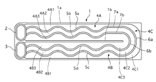
- the tube 1 is provided with an outer peripheral rib portion 1a that protrudes inward in the thickness direction (height direction) along the outer periphery thereof except for the inlet portion 2 and the outlet portion 3.
- a partition rib portion (corresponding to the partition portion) 1b is provided.
- the rib portion 1b extends on the other end side of the tube 1 to the vicinity of a U-turn flow path portion 4C described later.
- the rib portion 1b divides the tube 1 into two regions in the width direction, that is, an upstream linear flow channel portion 4A and a downstream linear flow channel portion 4B.
- the downstream end of the upstream linear flow path portion 4A and the upstream end of the downstream linear flow path portion 4B are communicated with each other on the other end side of the tube 1 through a U-turn flow path portion 4C.
- the inlet portion 2 and the outlet portion 3 are provided side by side in the width direction of the tube 1.
- a parallel circuit in which a part of engine cooling water or engine cooling water as a medium is introduced through the through hole of the inlet part 2 and the through hole of the outlet part 3, or an independent circuit different from the engine cooling water (for example, A cooling water circuit for the charger air cooler).
- the inlet portion 2 is connected to the upstream end of the upstream linear flow passage portion 4A, and the outlet portion 3 is connected to the downstream end of the downstream straight flow passage portion 4B.
- upstream flow paths 4A1, 4A2, and 4A3 are formed between the upper outer peripheral rib portion 1a and the partition rib portion 1b in FIG.
- the upstream flow paths 4A1, 4A2, and 4A3 protrude between the outer peripheral rib portion 1a and the partition rib portion 1b inward in the thickness direction (front side with respect to FIG. 1), and are wavy protruding portions that are wavy when viewed from above in the thickness direction.
- 5a and 5b are provided in parallel in a plurality of rows.
- three downstream flow paths 4B1, 4B2, and 4B3 are formed in the downstream straight flow path section 4B between the lower outer peripheral rib section 1a and the partition rib section 1b in FIG.
- the downstream flow paths 4B1, 4B2, and 4B3 protrude in the thickness direction between the outer peripheral rib portion 1a and the partition rib portion 1b, and are provided with a plurality of rows of wavy protruding portions 5c and 5d that are undulated when viewed from above in the thickness direction. .
- the wavy protrusions 5a, 5b, 5c, and 5d correspond to the wavy portions of the present invention.
- the U-turn channel portion 4C is provided inside the outer peripheral rib portion 1a on the other end side of the tube 1 and protrudes inward in the thickness direction, and has a plurality of arc-shaped protruding portions 6a that form an arc shape when viewed from above in the thickness direction. 6b are provided.
- the curvature is set so that the arcuate protrusion 6a is larger than the arcuate protrusion 6b.
- U-turn channel portion 4C between the outer peripheral rib portion 1a and the outer arc-shaped protruding portion 6a, between the outer arc-shaped protruding portion 6a and the inner arc-shaped protruding portion 6b, and between the inner arc-shaped protruding portion 6b and A total of three U-turn passages 4C1, 4C2, and 4C3 are formed between the partition rib portion 1b and the other end of the partition rib portion 1b.
- the curvatures of these U-turn passages 4C1, 4C2, and 4C3 are set so as to change the inflow direction and the outflow direction of the medium by 180 degrees.
- both end portions of the outer arcuate protrusion 6a are respectively connected to the downstream end of the wave-like protrusion 5a and the upstream end of the wave-like protrusion 5d.
- the medium flows through the inlet portion 2, the outer upstream channel 4A1, the outer U-turn channel 4C1, the outer downstream channel 4B1, and the outlet unit 3.
- both end portions of the inner arc-shaped protruding portion 6b are continuous with the downstream end of the wave-shaped protruding portion 5b and the upstream end of the wave-shaped protruding portion 5c, respectively.
- the medium passes through the inlet portion 2, the central upstream channel 4A2, the central U-turn channel 4C2, the central downstream channel 4B2, the outlet unit 3, and the inlet unit 2, the inner upstream channel 4A3.
- another tube plate is formed by molding.
- This other tube plate has a wave-like protrusion and an arc-like protrusion that become the shape and position of the image mirror-reflected by a mirror arranged in parallel above this toward FIG.
- the tube plate having the shape shown in FIG. 1 and the other tube plate are assembled.
- the corrugated protrusions, the arc-shaped protrusions, and the linear protrusions of both the tubes and plates face each other at the same position.
- both the tube plates are fixed to each other by brazing or the like such that the wavy protrusions, the arc-shaped protrusions, the linear protrusions, the outer peripheral ribs, and the partitioning ribs are fixed together by brazing or the like. can get.
- the cooling water flowing in from the inlet portion 2 is controlled by the wavy protrusions 5a and 5b in the upstream linear flow passage portion 4A, and the three upstream flows It flows meandering along the paths 4A1, 4A2, and 4A3, and flows into the U-turn flow path section 4C along the straight protrusions 7a and 7b.
- the flow direction of the cooling water is gradually changed by 180 degrees in the arcuate three U-turn passages 4C1, 4C2, and 4C3 along the arcuate protrusions 6a and 6b, and the three downstream parts Lead to side flow paths 4B1, 4B2, 4B3.
- the medium is meandering through the three corrugated downstream channels 4B1, 4B2, and 4B3 while being controlled by the corrugated protrusions 5c and 5d, and flows out from the outlet 3.
- the cooling water is stirred like a conventional dimple and flows through the tube. Since the cooling water meanders in a wavy manner, heat dissipation performance is ensured while suppressing an increase in flow resistance. In addition, as described above, the direction is gradually changed even in the U-turn portion. For this reason, it is suppressed that the cooling water hits strongly at this end portion of the tube and is damaged by erosion.
- the high-temperature compressed air flowing outside the tube is cooled by exchanging heat with cooling water when passing through the tube. Fuel is blown into this air, and this air-fuel mixture is burned in the combustion chamber of the engine.
- the tube of the heat exchanger according to the first embodiment can obtain the following effects. That is, since the upstream straight flow path portion 4A and the downstream straight flow path portion 4B are provided with the wave-like protrusions 5a, 5b, 5c, and 5d, respectively, the flow resistance when cooling water flows is suppressed and cooling is performed. The heat dissipation performance can be improved by allowing water to flow along the wavy protrusions 5a, 5b, 5c, and 5d.
- the tube 1 Since the tube 1 is manufactured by assembling the half-divided tube plates with each other, the tube 1 can be manufactured easily and inexpensively. Also, in this case, the wavy protrusions 5a, 5b, 5c, 5d of both tube plates are arranged at the same position so that the wavy protrusions 5a, 5b, 5c, 5d face each other continuously. So you can meander. Further, since the end portions of the arc-shaped projecting portions 6a and 6b of the U-turn channel portion 4C are arranged so as to straddle the downstream end of the partition rib portion 1b, the disturbance of the cooling water here can be suppressed. That is, the flow between the straight flow passage portions (between the upstream straight flow passage portion 4A and the downstream straight flow passage portion 4B) is smoothly performed, and the flow resistance can be suppressed.
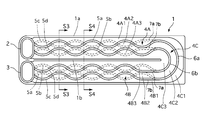
- FIG. 2 shows a tube 1 of the heat exchanger according to the second embodiment.
- the tube 1 of the heat exchanger of the second embodiment two tube plates having the same configuration as the first embodiment are prepared.
- One of the tubes is inverted and assembled to the other to form the tube 1.
- the arcuate protrusions 6a and 6b of the 5b, 5c and 5d and the U-turn channel 4C are as shown by broken lines in FIG.
- the wavy protrusions 5a, 5b, 5c and 5d of both tube plates and the straight protrusions 7a and 7b are only partly facing each other, and the other parts are shifted from each other in the width direction of the tube 1. It becomes like this.
- the arc-shaped protrusions 6a and 6b of the U-turn channel 4C are in the same position and continuously face each other. That is, a pair of corrugated protrusions 5a and 5b and corrugated protrusions 5c and 5d are alternately arranged in parallel.
- each of the corrugated protrusions 5a and 5b (or the corrugated protrusions 5c and 5d), which is a pair of corrugated parts, crosses the corrugated part, and only the parts face each other.
- Other configurations are the same as those of the first embodiment.
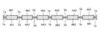
- FIG. 3 is a cross-sectional view taken along the line S3-S3 passing through the non-facing portions in FIG. 2
- FIG. 4 is a cross-sectional view taken along the line S4-S4 passing through the portions facing each other. .
- the cooling water is not greatly agitated unlike many dimples in the prior art.
- the tube 1 of the heat exchanger according to the second embodiment since the agitation can be performed as compared with the first embodiment, the heat radiation performance is improved. In this case, the flow resistance is slightly increased as compared with the first embodiment. However, since the same tube plate can be used for both tube plates to be assembled, the tube 1 can be manufactured at a lower cost than in the case of the first embodiment.
- the present invention has been described based on the above-described embodiments.
- the present invention is not limited to the above-described embodiments, and is included in the present invention even when there is a design change or the like without departing from the gist of the present invention.
- the wavy protrusions 5a, 5b, 5c, and 5d are provided in both the upstream linear flow path portion 4A and the downstream straight flow path portion 4B, but only in one of them. Also good.
- the medium may be guided using inner fins in place of the wavy protrusions 5a, 5b, 5c, 5d and the arc-shaped protrusions 6a, 6b. By configuring the inner fin, the degree of freedom in setting the wavy shape is increased.
- both tubes of the same shape By assembling the plates, the tube 1 can be manufactured at a lower cost.
- tube of the heat exchanger of the present invention is used for the water-cooled charge air cooler, it is not limited to this and may be used for other heat exchangers.
- Tube (heat exchanger tube) 1a Outer peripheral rib 1b Partition rib (partition) 2 Inlet 3 Outlet 4A Upstream straight channel 4B Downstream straight channel 4C U-turn channel 4A1, 4A2, 4A3 Upstream channel 4B1, 4B2, 4B3 Downstream channel 4C1, 4C2, 4C3 U Turn passage 5a, 5b, 5c, 5d Corrugated protrusion 6a, 6b Arc-shaped protrusion 7a, 7b Linear protrusion
Abstract
Description
これらの従来の熱交換器用チューブは、両外側が出入口を除いてビードで形成され、その中央部に仕切りビードが設けられて媒体がU字状に流れる流路が形成されたチューブ部材を有している。この流路には、流通する媒体を撹拌して放熱性能を向上させるために、内側へ向けて突出される多数の突出部が設けられている。このように形成された2個のチューブ・プレートは、互いに組み付けられてチューブを構成する。 As conventional heat exchanger tubes, those described in
These conventional heat exchanger tubes have tube members formed on both outer sides with beads except for the entrance and exit, with a partition bead provided at the center, and a flow path through which the medium flows in a U-shape. ing. The flow path is provided with a number of protrusions protruding inward to stir the circulating medium and improve the heat dissipation performance. The two tube plates formed in this way are assembled together to form a tube.
媒体の入口部と、
媒体の出口部と、
入口部および出口部間を結び、媒体が流通する上流側直線流路部および下流側直線流路部と、
を備えた熱交換器用チューブにおいて、
上流側直線流路部および下流側直線流路部の少なくとも一方に、流路内に配置し、チューブの長手方向に延在、かつ連続し媒体を導く波状部を設けた、
ことを特徴とする。 For this purpose, the heat exchanger tube according to the invention is
A medium inlet,
A media outlet;
An upstream straight flow path section and a downstream straight flow path section through which the medium flows, connecting the inlet section and the outlet section,
In a heat exchanger tube with
At least one of the upstream linear flow channel portion and the downstream linear flow channel portion is disposed in the flow channel, and is provided with a wave-shaped portion that extends in the longitudinal direction of the tube and continuously guides the medium.
It is characterized by that.
図1に示すように、実施例1の熱交換器用チューブ1は、本実施例では、内燃機関エンジンに付属され、吸入空気を圧縮するチャージャ(ターボチャージャやスーパーチャージャ)の圧縮空気をエンジンの冷却水で冷却する水冷式チャージ・エア・クーラに用いられる。 First, the overall configuration of the heat exchanger tube of Example 1 will be described.
As shown in FIG. 1, the
チューブ1は、入口部2と出口部3とを除き、その外周に沿って、その厚さ方向(高さ方向)内方に向けて突出した外周リブ部1aが設けられている。
また、チューブ1の一端側に配置した入口部2と出口部3の間からチューブの長手方向(図1の左右方向)に向けて、チューブ1の幅方向(図1の上下方向)の中央位置で、仕切りリブ部(仕切り部に相当)1bが設けられている。リブ部1bは、チューブ1の他端側で、後で説明するUターン流路部4C付近まで延在されている。リブ部1bは、チューブ1を幅方向に2つの領域、すなわち上流側直線流路部4Aと、下流側直線流路部4Bとに区分する。 The
The
In addition, the central position of the
一方、入口部2と出口部3とは、チューブ1の幅方向に並べて設けられている。入口部2の貫通孔と出口部3の貫通孔を介して媒体であるエンジンの冷却水やエンジンの冷却水の一部を導入した並列回路、又はエンジンの冷却水とは異なる独立した回路(例えばチャージャ・エア・クーラ用の冷却水回路)が出入りすることができるようにしてある。入口部2は上流側直線流路部4Aの上流側端に、また出口部3は下流側直線流路部4Bの下流側端にそれぞれ連続するように接続される。 The downstream end of the upstream linear
On the other hand, the
同様に、下流側直線流路部4Bには、図1の下側の外周リブ部1aと仕切りリブ部1bとの間に3本の下流側流路4B1、4B2、4B3が形成される。下流側流路4B1、4B2、4B3は、外周リブ部1a、仕切りリブ部1b間に厚さ方向に突出し、厚さ方向上方からみて波状をなす波状突出部5c、5dが複数列並行に設けられる。
なお、波状突出部5a、5b、5c、5dは、本発明の波状部に相当する。 In the upstream straight
Similarly, three downstream flow paths 4B1, 4B2, and 4B3 are formed in the downstream straight
The
したがって、Uターン流路部4Cでは、外周リブ部1aと外側の弧状突出部6aとの間、外側の弧状突出部6aと内側の弧状突出部6bとの間、および内側の弧状突出部6bと仕切りリブ部1bの他端側端部との間に、それぞれ合計3本のUターン通路4C1、4C2、4C3の流路が形成される。なお、これらのUターン通路4C1、4C2、4C3は、媒体の流入方向と流出方向を180度方向転換させるようにそれらの曲率が設定されている。 On the other hand, the U-turn
Therefore, in the
また、内側の弧状突出部6bの両端部は、波状突出部5bの下流側端と波状突出部5cの上流側端にそれぞれ連続する。これにより、媒体は、入口部2、中央の上流側流路4A2、中央のUターン通路4C2、中央の下流側流路4B2、出口部3を、また入口部2、内側の上流側流路4A3、内側のUターン通路4C3、外側の下流側流路4B3、出口部3を流れる。 In this case, both end portions of the outer
Further, both end portions of the inner arc-
そうして、図1の形状のチューブ・プレートと上記別のチューブ・プレートとが、組み付けられる。この組み付け状態では、両チューブ・プレートの波状突出部同士、弧状突出部同士、直線突出部同士は、同じ位置で互いに対面した状態となる。
この状態で、両チューブ・プレートは、これらの波状突出部同士、弧状突出部同士、直線突出部同士、外周リブ部同士、仕切りリブ部同士がロウ付け等で固着されることで、チューブ1が得られる。 Although not shown, another tube plate is formed by molding. This other tube plate has a wave-like protrusion and an arc-like protrusion that become the shape and position of the image mirror-reflected by a mirror arranged in parallel above this toward FIG.
Thus, the tube plate having the shape shown in FIG. 1 and the other tube plate are assembled. In this assembled state, the corrugated protrusions, the arc-shaped protrusions, and the linear protrusions of both the tubes and plates face each other at the same position.
In this state, both the tube plates are fixed to each other by brazing or the like such that the wavy protrusions, the arc-shaped protrusions, the linear protrusions, the outer peripheral ribs, and the partitioning ribs are fixed together by brazing or the like. can get.
Uターン流路部4Cでは、弧状突出部6a、6bに沿って円弧の3本のUターン通路4C1、4C2、4C3内で、冷却水の流れ方向を徐々に180度変更し、3本の下流側流路4B1、4B2、4B3へ導く。
その後、媒体は、波状突出部5c、5dでコントロールされながら、3本の波状の下流側流路4B1、4B2、4B3内を蛇行して進み、出口部3から流出される。 In the heat exchanger tube configured as described above, the cooling water flowing in from the
In the U-turn
Thereafter, the medium is meandering through the three corrugated downstream channels 4B1, 4B2, and 4B3 while being controlled by the
一方、このチューブの外側を流れる高温の圧縮空気は、チューブを通るとき、冷却水と熱交換を行うことで、冷却される。この空気には、燃料が吹き込まれて、この混合気がエンジンの燃焼室で燃焼される。 In this manner, the cooling water is stirred like a conventional dimple and flows through the tube. Since the cooling water meanders in a wavy manner, heat dissipation performance is ensured while suppressing an increase in flow resistance. In addition, as described above, the direction is gradually changed even in the U-turn portion. For this reason, it is suppressed that the cooling water hits strongly at this end portion of the tube and is damaged by erosion.
On the other hand, the high-temperature compressed air flowing outside the tube is cooled by exchanging heat with cooling water when passing through the tube. Fuel is blown into this air, and this air-fuel mixture is burned in the combustion chamber of the engine.
すなわち、上流側直線流路部4Aと下流側直線流路部4Bとに、それぞれ波状突出部5a、5b、5c、5dを設けたので、冷却水が流れる場合の流通抵抗を抑制し、かつ冷却水が波状突出部5a、5b、5c、5dに沿って流れることで放熱性能を向上させることできる。 As described above, the tube of the heat exchanger according to the first embodiment can obtain the following effects.
That is, since the upstream straight
また、この場合、両チューブ・プレートの波状突出部5a、5b、5c、5dが同じ位置となるように配置し、波状突出部5a、5b、5c、5d同士が連続して対面するようにしたので蛇行するようにすることができる。
また、Uターン流路部4Cの弧状突出部6a、6bの端部が、仕切りリブ部1bの下流側端を跨ぐように配置したので、ここでの冷却水の乱れを抑制することができる。すなわち、直線流路部間(上流側直線流路部4Aと下流側直線流路部4Bの間)の流れがスムーズに行われ、流通抵抗を抑制することができる。 Since the
Also, in this case, the
Further, since the end portions of the arc-shaped projecting
そして、一方が反転されて他方に組み付けられてチューブ1が構成される。
この場合、実施例1の鏡面反射した別チューブ・プレートを用いるわけではないので、他方のチューブ・プレートに形成した上流側直線流路部4A、下流側直線流路部4Bの波状突出部5a、5b、5c、5dやUターン流路部4Cの弧状突出部6a、6bは、図2に破線で示すようになる。 FIG. 2 shows a
One of the tubes is inverted and assembled to the other to form the
In this case, since the mirror-reflected separate tube plate of Example 1 is not used, the upstream linear
つまり、一対の波状部である波状突出部5a、5bと波状突出部5c、5dとが、交互に並列配置した状態になる。これにより、波状部は、一対の波状部である波状突出部5a、5b(または、波状突出部5c、5d)のそれぞれの一部分のみが交差し、該一部分同士のみが対面する。
その他の構成は、実施例1と同様である。 In this case, the
That is, a pair of
Other configurations are the same as those of the first embodiment.
この断面形状をみて分かるように、従来技術の多数のディンプルのように、冷却水を大きく撹拌するようなことはない。 3 is a cross-sectional view taken along the line S3-S3 passing through the non-facing portions in FIG. 2, and FIG. 4 is a cross-sectional view taken along the line S4-S4 passing through the portions facing each other. .
As can be seen from this cross-sectional shape, the cooling water is not greatly agitated unlike many dimples in the prior art.
ただし、組み付ける両チューブ・プレートとも同じチューブ・プレートを用いることができるので、実施例1の場合より安価にチューブ1を製造することができるようになる。 In the
However, since the same tube plate can be used for both tube plates to be assembled, the
また、波状突出部5a、5b、5c、5dや弧状突出部6a、6bに代えて、インナ・フィンを用いて媒体を導くようにしてもよい。インナ・フィンで構成することにより、波状部形状の設定自由度が高まる。 For example, in the first embodiment, the
Further, the medium may be guided using inner fins in place of the
1a 外周リブ部
1b 仕切りリブ部(仕切り部)
2 入口部
3 出口部
4A 上流側直線流路部
4B 下流側直線流路部
4C Uターン流路部
4A1、4A2、4A3 上流側流路
4B1、4B2、4B3 下流側流路
4C1、4C2、4C3 Uターン通路
5a、5b、5c、5d 波状突出部
6a、6b 弧状突出部
7a、7b 直線突出部 1 Tube (heat exchanger tube)
1a Outer
2
Claims (10)
- 媒体の入口部と、
前記媒体の出口部と、
前記入口部および前記出口部間を結び、媒体が流通する上流側直線流路部および下流側直線流路部と、
を備えた熱交換器用チューブにおいて、
前記上流側直線流路部および前記下流側直線流路部の少なくとも一方に、流路内に配置し、チューブの長手方向に延在、かつ連続し媒体を導く波状部を設けた、
ことを特徴とする熱交換器用チューブ。 A medium inlet,
An outlet portion of the medium;
An upstream straight flow path section and a downstream straight flow path section through which the medium flows through the inlet section and the outlet section,
In a heat exchanger tube with
At least one of the upstream linear flow channel portion and the downstream linear flow channel portion is provided in the flow channel, and provided with a wave-shaped portion that extends in the longitudinal direction of the tube and continuously guides the medium.
This is a heat exchanger tube. - 請求項1に記載の熱交換器用チューブにおいて、
前記波状部は、前記チューブの内側に突出する突出部である、
ことを特徴とする熱交換器用チューブ。 In the heat exchanger tube according to claim 1,
The wavy portion is a protruding portion that protrudes to the inside of the tube.
This is a heat exchanger tube. - 請求項2に記載の熱交換器用チューブにおいて、
波状の前記突出部は、インナ・フィンである、
ことを特徴とする熱交換器用チューブ。 The heat exchanger tube according to claim 2,
The wavy protrusion is an inner fin,
This is a heat exchanger tube. - 請求項1乃至請求項3のいずれか1項に記載の熱交換器用チューブにおいて、
前記入口部と前記出口部とは、前記チューブの一端側に配置し、該チューブの他端側には前記上流側直線流路部および前記下流側直線流路部をつなぐUターン流路部を設け、該Uターン流路部には前記チューブの内側に突出し、前記上流側直線流路部および前記下流側直線流路部の少なくとも一方に設けた前記波状部に連続する弧状の突出部を設けた、
ことを特徴とする熱交換器用チューブ。 In the heat exchanger tube according to any one of claims 1 to 3,
The inlet portion and the outlet portion are arranged on one end side of the tube, and a U-turn flow passage portion that connects the upstream straight flow passage portion and the downstream straight flow passage portion to the other end side of the tube. The U-turn flow path is provided with an arc-shaped protrusion that protrudes inside the tube and continues to the wave-shaped part provided in at least one of the upstream straight flow path and the downstream straight flow path. The
This is a heat exchanger tube. - 請求項1乃至請求項4のいずれか1項に記載の熱交換器用チューブにおいて、
前記波状部は、前記チューブの厚さ方向に配置した、複数の波状部からなる、
ことを特徴とする熱交換器用チューブ。 In the heat exchanger tube according to any one of claims 1 to 4,
The wavy portion is composed of a plurality of wavy portions arranged in the thickness direction of the tube.
This is a heat exchanger tube. - 請求項5に記載の熱交換器用チューブにおいて、
一対の前記波状部が同じ位置となるように配置し、該波状部同士が連続して対面するようにした、
ことを特徴とする熱交換器用チューブ。 In the heat exchanger tube according to claim 5,
A pair of the wavy portions are arranged at the same position, and the wavy portions are continuously facing each other.
This is a heat exchanger tube. - 請求項5に記載の熱交換器用チューブにおいて、
前記波状部は、前記一対の波状部のそれぞれの一部分のみが交差し、該一部分同士のみが対面する、
ことを特徴とする熱交換器用チューブ。 In the heat exchanger tube according to claim 5,
The wavy portions intersect only a part of each of the pair of wavy portions, and only the portions face each other.
This is a heat exchanger tube. - 請求項5に記載の熱交換器用チューブにおいて、
前記一対の波状部は、交互に並列配置した、
ことを特徴とする熱交換器用チューブ。 In the heat exchanger tube according to claim 5,
The pair of wavy portions are alternately arranged in parallel.
This is a heat exchanger tube. - 請求項1乃至8のいずれか1項に記載の熱交換器用チューブにおいて、
前記Uターン流路部の弧状突出部の端部は、前記上流側直線流路部および前記下流側直線流路部を分ける仕切り部の下流側端を、内方に跨ぐように配置した、
ことを特徴とする熱交換器用チューブ。 In the heat exchanger tube according to any one of claims 1 to 8,
The end of the arcuate protrusion of the U-turn channel is arranged so as to straddle the downstream end of the partition that divides the upstream linear channel and the downstream linear channel.
This is a heat exchanger tube. - 請求項1乃至9のいずれか1項に記載の熱交換器用チューブにおいて、
前記チューブ内を流通する媒体は、冷却水であり、
前記熱交換器用チューブは、前記冷却水と前記チューブの外側を流通する圧縮空気とが熱交換して圧縮空気を冷却する水冷式チャージ・エア・クーラのチューブである、
ことを特徴とする熱交換器用チューブ。 In the heat exchanger tube according to any one of claims 1 to 9,
The medium circulating in the tube is cooling water,
The heat exchanger tube is a tube of a water-cooled charge air cooler in which the cooling water and compressed air flowing outside the tube exchange heat to cool the compressed air.
This is a heat exchanger tube.
Priority Applications (3)
| Application Number | Priority Date | Filing Date | Title |
|---|---|---|---|
| US14/438,893 US20150300755A1 (en) | 2012-10-30 | 2013-10-07 | Heat exchanger tube |
| DE112013005192.3T DE112013005192T5 (en) | 2012-10-30 | 2013-10-07 | heat exchanger tube |
| CN201380057125.1A CN104769381A (en) | 2012-10-30 | 2013-10-07 | Heat exchanger tube |
Applications Claiming Priority (2)
| Application Number | Priority Date | Filing Date | Title |
|---|---|---|---|
| JP2012-239052 | 2012-10-30 | ||
| JP2012239052A JP5921413B2 (en) | 2012-10-30 | 2012-10-30 | Tube for heat exchanger |
Publications (1)
| Publication Number | Publication Date |
|---|---|
| WO2014069175A1 true WO2014069175A1 (en) | 2014-05-08 |
Family
ID=50627091
Family Applications (1)
| Application Number | Title | Priority Date | Filing Date |
|---|---|---|---|
| PCT/JP2013/077244 WO2014069175A1 (en) | 2012-10-30 | 2013-10-07 | Heat exchanger tube |
Country Status (5)
| Country | Link |
|---|---|
| US (1) | US20150300755A1 (en) |
| JP (1) | JP5921413B2 (en) |
| CN (1) | CN104769381A (en) |
| DE (1) | DE112013005192T5 (en) |
| WO (1) | WO2014069175A1 (en) |
Cited By (1)
| Publication number | Priority date | Publication date | Assignee | Title |
|---|---|---|---|---|
| WO2017115436A1 (en) * | 2015-12-28 | 2017-07-06 | 国立大学法人東京大学 | Heat exchanger |
Families Citing this family (5)
| Publication number | Priority date | Publication date | Assignee | Title |
|---|---|---|---|---|
| CN106796050B (en) * | 2014-10-08 | 2019-08-09 | 贝卡尔特燃烧技术股份有限公司 | Heat exchanger |
| JP6531325B2 (en) * | 2015-02-18 | 2019-06-19 | 有限会社和氣製作所 | Heat exchanger |
| DE102016205353A1 (en) * | 2016-03-31 | 2017-10-05 | Mahle International Gmbh | The stacked-plate heat exchanger |
| JP2018013262A (en) * | 2016-07-19 | 2018-01-25 | カルソニックカンセイ株式会社 | Heat exchanger |
| JP2019100565A (en) * | 2017-11-29 | 2019-06-24 | パナソニックIpマネジメント株式会社 | Heat exchanger and refrigeration system using the same |
Citations (4)
| Publication number | Priority date | Publication date | Assignee | Title |
|---|---|---|---|---|
| JPS6273095A (en) * | 1985-09-25 | 1987-04-03 | Nippon Denso Co Ltd | Lamination type heat exchanger |
| JP2005195190A (en) * | 2003-12-26 | 2005-07-21 | Toyo Radiator Co Ltd | Multiplate heat exchanger |
| JP2008144997A (en) * | 2006-12-07 | 2008-06-26 | T Rad Co Ltd | Pressure-proof heat exchanger |
| WO2009013802A1 (en) * | 2007-07-23 | 2009-01-29 | Tokyo Roki Co. Ltd. | Plate laminate type heat exchanger |
Family Cites Families (7)
| Publication number | Priority date | Publication date | Assignee | Title |
|---|---|---|---|---|
| JP2615730B2 (en) * | 1987-12-26 | 1997-06-04 | アイシン精機株式会社 | Plate heat exchanger |
| KR100200657B1 (en) * | 1996-12-19 | 1999-06-15 | 신영주 | Tube for heat exchanger |
| JP4122670B2 (en) * | 1999-01-28 | 2008-07-23 | 株式会社デンソー | Heat exchanger |
| JP2005180714A (en) * | 2003-12-16 | 2005-07-07 | Calsonic Kansei Corp | Heat exchanger and inner fin used by it |
| JP4999146B2 (en) * | 2006-01-13 | 2012-08-15 | 株式会社ティラド | Inner fin and heat sink equipped with the inner fin |
| JP2010127143A (en) * | 2008-11-26 | 2010-06-10 | Calsonic Kansei Corp | Charge air cooler |
| DE102008064090A1 (en) * | 2008-12-19 | 2010-08-12 | Mahle International Gmbh | exhaust gas cooler |
-
2012
- 2012-10-30 JP JP2012239052A patent/JP5921413B2/en active Active
-
2013
- 2013-10-07 WO PCT/JP2013/077244 patent/WO2014069175A1/en active Application Filing
- 2013-10-07 US US14/438,893 patent/US20150300755A1/en not_active Abandoned
- 2013-10-07 DE DE112013005192.3T patent/DE112013005192T5/en active Pending
- 2013-10-07 CN CN201380057125.1A patent/CN104769381A/en active Pending
Patent Citations (4)
| Publication number | Priority date | Publication date | Assignee | Title |
|---|---|---|---|---|
| JPS6273095A (en) * | 1985-09-25 | 1987-04-03 | Nippon Denso Co Ltd | Lamination type heat exchanger |
| JP2005195190A (en) * | 2003-12-26 | 2005-07-21 | Toyo Radiator Co Ltd | Multiplate heat exchanger |
| JP2008144997A (en) * | 2006-12-07 | 2008-06-26 | T Rad Co Ltd | Pressure-proof heat exchanger |
| WO2009013802A1 (en) * | 2007-07-23 | 2009-01-29 | Tokyo Roki Co. Ltd. | Plate laminate type heat exchanger |
Cited By (1)
| Publication number | Priority date | Publication date | Assignee | Title |
|---|---|---|---|---|
| WO2017115436A1 (en) * | 2015-12-28 | 2017-07-06 | 国立大学法人東京大学 | Heat exchanger |
Also Published As
| Publication number | Publication date |
|---|---|
| CN104769381A (en) | 2015-07-08 |
| DE112013005192T5 (en) | 2015-08-27 |
| JP5921413B2 (en) | 2016-05-24 |
| US20150300755A1 (en) | 2015-10-22 |
| JP2014088994A (en) | 2014-05-15 |
Similar Documents
| Publication | Publication Date | Title |
|---|---|---|
| WO2014069175A1 (en) | Heat exchanger tube | |
| US9951995B2 (en) | Heat exchanger with self-retaining bypass seal | |
| JP4756585B2 (en) | Heat exchanger tube for heat exchanger | |
| US9328968B2 (en) | Low profile, split flow charge air cooler with uniform flow exit manifold | |
| US8069905B2 (en) | EGR gas cooling device | |
| US10047663B2 (en) | Charge air cooler with multi-piece plastic housing | |
| WO2018180058A1 (en) | Heat exchanger | |
| JP4175340B2 (en) | Heat exchanger | |
| US20070193732A1 (en) | Heat exchanger | |
| JP5395783B2 (en) | Heat exchanger with tube bundle | |
| US9874407B2 (en) | Heat exchanger | |
| CA3037066A1 (en) | Heat exchanger having aerodynamic features to improve performance | |
| JP2015532708A (en) | Improved exhaust gas recirculation device and method for forming the same | |
| JP2006336890A (en) | Intercooler | |
| JP6577282B2 (en) | Heat exchanger | |
| JP6197190B2 (en) | Tube for heat exchanger | |
| JP2013213424A (en) | Exhaust gas heat exchanger | |
| JP6706713B1 (en) | Heat exchanger | |
| JP6496067B1 (en) | Heat exchanger | |
| US20180266367A1 (en) | Exhaust heat recovery device | |
| JP2014088995A (en) | Tube for heat exchanger | |
| JP6687649B2 (en) | Exhaust heat recovery device | |
| JP6699588B2 (en) | Heat exchanger | |
| JP2016200071A (en) | EGR gas cooler | |
| KR20080065846A (en) | Oil cooler |
Legal Events
| Date | Code | Title | Description |
|---|---|---|---|
| 121 | Ep: the epo has been informed by wipo that ep was designated in this application |
Ref document number: 13850497 Country of ref document: EP Kind code of ref document: A1 |
|
| WWE | Wipo information: entry into national phase |
Ref document number: 14438893 Country of ref document: US |
|
| WWE | Wipo information: entry into national phase |
Ref document number: 1120130051923 Country of ref document: DE Ref document number: 112013005192 Country of ref document: DE |
|
| 122 | Ep: pct application non-entry in european phase |
Ref document number: 13850497 Country of ref document: EP Kind code of ref document: A1 |