WO2014068630A1 - 中継装置および送受信方法 - Google Patents
中継装置および送受信方法 Download PDFInfo
- Publication number
- WO2014068630A1 WO2014068630A1 PCT/JP2012/077825 JP2012077825W WO2014068630A1 WO 2014068630 A1 WO2014068630 A1 WO 2014068630A1 JP 2012077825 W JP2012077825 W JP 2012077825W WO 2014068630 A1 WO2014068630 A1 WO 2014068630A1
- Authority
- WO
- WIPO (PCT)
- Prior art keywords
- video data
- relay device
- relay
- video
- message
- Prior art date
- Legal status (The legal status is an assumption and is not a legal conclusion. Google has not performed a legal analysis and makes no representation as to the accuracy of the status listed.)
- Ceased
Links
Images







Classifications
-
- H—ELECTRICITY
- H04—ELECTRIC COMMUNICATION TECHNIQUE
- H04N—PICTORIAL COMMUNICATION, e.g. TELEVISION
- H04N21/00—Selective content distribution, e.g. interactive television or video on demand [VOD]
- H04N21/60—Network structure or processes for video distribution between server and client or between remote clients; Control signalling between clients, server and network components; Transmission of management data between server and client, e.g. sending from server to client commands for recording incoming content stream; Communication details between server and client
- H04N21/65—Transmission of management data between client and server
- H04N21/658—Transmission by the client directed to the server
- H04N21/6587—Control parameters, e.g. trick play commands, viewpoint selection
-
- H—ELECTRICITY
- H04—ELECTRIC COMMUNICATION TECHNIQUE
- H04N—PICTORIAL COMMUNICATION, e.g. TELEVISION
- H04N21/00—Selective content distribution, e.g. interactive television or video on demand [VOD]
- H04N21/20—Servers specifically adapted for the distribution of content, e.g. VOD servers; Operations thereof
- H04N21/23—Processing of content or additional data; Elementary server operations; Server middleware
- H04N21/234—Processing of video elementary streams, e.g. splicing of video streams or manipulating encoded video stream scene graphs
- H04N21/2343—Processing of video elementary streams, e.g. splicing of video streams or manipulating encoded video stream scene graphs involving reformatting operations of video signals for distribution or compliance with end-user requests or end-user device requirements
- H04N21/23439—Processing of video elementary streams, e.g. splicing of video streams or manipulating encoded video stream scene graphs involving reformatting operations of video signals for distribution or compliance with end-user requests or end-user device requirements for generating different versions
Definitions
- the technical field relates to transmission and reception of video signals.
- Patent Document 1 describes “a digital display monitor having two VESA-DP connectors” regarding “serial transmission of a high-definition video signal from a source device to one or more sink devices” (see Patent Document 1 [0001]). One of which receives a plurality of serial video lane signals in a pluggable manner, and the other receives the received video in a further monitor detachably connected in a daisy chain manner to a first monitor. “Transfer (relay) all of the signal” (see Patent Document 1 [0012]), “Selectively respond to a part of data passed through and display it locally” (see Patent Document 1 [0013]) ) Is disclosed.
- any prior art document it is considered that a plurality of video sources (or relay devices connected to the video sources) and a plurality of display devices (or relay devices connected to the display devices) are daisy chain connected. Not.
- the present application includes a plurality of means for solving the above-mentioned problems.
- a relay device having an input unit capable of inputting video data and an output unit capable of outputting video data is input to the input unit.
- the information about the amount of video data that can be transmitted by the relay device and the information about the amount of video data transmitted by the relay device are added to the message and output from the output unit.
- Example of message in the first embodiment An example of a video transmission / reception system configuration of the second embodiment.
- the video data output from the video source is the maximum, so the video data output from the display device connected to the daisy chain to the next display device is the video data output from the video source. Do not exceed the amount. Therefore, the video source can easily manage the display capability of each display device and each transmission amount of the daisy chain connection.
- video data output from the plurality of video sources may pass through the same daisy chain connection device. Depending on the relay capability of the daisy chain connection device, the video source may need to adjust the amount of output data according to the output data of the other video source.
- the amount of data output from the video source is determined after obtaining information on the relay capability of the daisy chain connection device on the path from the video source to the display device and the usage status thereof. Further, when the relay capability is insufficient, the output data of other video sources is adjusted.
- FIG. 1 is a block diagram showing an example of a video transmission / reception system configuration of the present embodiment.
- PC Personal Computer
- PC 112 Player 113 that reproduces video recorded on a recording medium such as an optical disc
- STB Set Top Box
- STB Set Top Box
- the relay apparatuses 101 to 106 include input terminals for inputting video data output from the video sources 111 to 116 in addition to the input / output terminals for daisy chain connection.
- the video sources 111 to 116 may be provided with the functions of the relay apparatuses 101 to 106, and may be video sources compatible with daisy chain connection.
- the relay devices 107 to 110 are provided with output terminals for outputting video data to the display devices 117 to 120 in addition to the input / output terminals for daisy chain connection.
- the display devices 117 to 120 may be provided with the functions of the relay devices 107 to 110, and may be display devices compatible with daisy chain connection.
- Relay devices 101 to 110 are daisy chain connected via cables 121 to 129.
- the relay device 101 at the end of the daisy chain connection has an input terminal, and the relay device 110 has an output terminal that is not connected to another relay device.
- FIG. 2 shows a configuration example of the relay apparatuses 101 to 106 connected to the video source.
- the relay device 101 is shown, but the configurations 102 to 106 have the same configuration.
- the relay apparatus 101 has an input terminal 221 for inputting video data from a video source, an input terminal 211 for daisy chain connection, and an output terminal 212.
- the input terminal 211 has four lanes 136 to 139 for inputting video data and a communication lane 140.
- the output terminal 212 includes four lanes 131 to 134 for outputting video data and a communication lane 135.
- 156 to 159 are input circuits
- 151 to 154 are switches
- 141 to 144 are output circuits
- 170 is a communication unit.
- Reference numeral 167 denotes a receiving unit
- 168 denotes an encryption unit
- 165 denotes an output selection unit.
- the video data input from the input terminal 211 to the four lanes 136 to 139 is, for example, differential data of serial data, and the input circuits 156 to 159 reproduce digital data from signals whose waveforms are deteriorated during cable transmission. If the switches 152 to 154 are in the ON state, those digital data are output to the lanes 132 to 134 through the output circuits 142 to 144.
- the video data input from the video source to the input terminal 221 is received by the receiving unit 167, and then encrypted by the encryption unit 168 if necessary for content protection or the like.
- the output data of the encryption unit 168 is sent to the output circuit 141 by the output selection unit 165.
- the output circuit 141 outputs only the output from the output selection unit 165 to the lane 131.
- the video data of the video source input to the input terminal 221 is output from the lane 131, and the video data of the lanes 137 to 139 input to the input terminal 211 is output from the lanes 132 to 134.
- the communication unit 170 outputs the video data input from the video source to the input terminal 221 to which lane of the output terminal 212, or outputs the video data of each lane input to the input terminal 211 to each lane of the output terminal. In order to obtain information necessary to determine whether or not, a message exchanged with another relay apparatus is performed.
- FIG. 3 shows another configuration example of the relay apparatuses 101 to 106 connected to the video source. Similar to FIG. 2, the relay device 101 is shown in FIG. 3, but 102 to 106 have the same configuration. The same functions and configurations as those in FIG. 2 are denoted by the same reference numerals, and the description thereof is omitted.
- the input circuit 156 reproduces the video data input from the lane 136 of the input terminal 211 into digital data, and the video data is transmitted to the code decoding unit 155 through the input selection unit 166.
- the encoding / decoding unit 155 decodes video data encoded by, for example, an 8B / 10B system (a system in which 8-bit data is converted into 10-bit data and transferred) for cable transmission (encryption for content protection or the like). If processing is in progress, encryption / decryption is not performed).
- the multiplex encoding unit 169 performs multiplexing and encoding processing suitable for cable transmission on the encrypted video data from the encoding / decoding unit 155 and the encrypted video data from the encryption unit 168, and This is transmitted to the output circuit of the lane to be transmitted via the output selection unit 165. In FIG. 3, the output circuit 141 selected by the output selection unit 165 outputs to the lane 131 of the output terminal 212.
- the video data output from the lane 131 is only the video data input to the input terminal 221, but in FIG. 3, it can be output together with the video data input to the lane 136 of the input terminal 211.
- Effective use of lanes When sending two video data in one lane, it is preferable to set each video source to send a video format that does not exceed the maximum transmission capacity of the lane. If the video source cannot adjust the video data amount, the receiving unit 167 may perform video format conversion or data amount compression processing. If it is necessary to reduce the amount of data in the lane 156 of the video input terminal 211, the encryption processing is performed after performing video format conversion or data amount compression processing after performing encryption / decryption in addition to the encoding / decoding unit 155. Good.
- the video data composition unit 160 including the switches 151 to 154, the input selection unit 166, the code decoding unit 155, the multiplex coding unit 169, and the output selection unit 165 includes the input video data at the input terminal 211 and the input video at the input terminal 221. Synthesize the data.
- the video data synthesizing unit 160 is the same not only when outputting the video data of the input terminal 221 to one lane but also when outputting one video data using a plurality of lanes such as two or four. It can be realized by configuration.
- an encoding / decoding unit for cable transmission and a re-encoding unit may be added between the input circuits 157 to 159 and the output circuits 142 to 144 in FIG.
- Video data may be delayed due to decoding and re-encoding.
- the generated delay time is added to the delay time assigned to the received video data and output, and the relay device connected to the display device adds the delay time given to the video data and the display delay time of the display device.
- the video source can grasp the display delay time of the display device.
- the video source may send a message instructing the total value of the video data transmission delay time and the display delay time to each display device, and each display device may display according to the display delay time.
- FIG. 4 shows a configuration example of the relay devices 107 to 110 connected to the display device.
- the relay device 107 is shown, but the configurations 108 to 110 have the same configuration.
- the relay device 107 has an input terminal 215 and an output terminal 216 for daisy chain connection, and an output terminal 222 for outputting video data to the display device.
- the input terminal 215 has four lanes 171 to 174 for inputting video data and a communication lane 175.
- the output terminal 216 has four lanes 176 to 179 for outputting video data and a communication lane 180.
- 181 to 184 are input circuits, 196 to 199 are output circuits, and 195 is a communication unit.
- Reference numerals 185 and 187 are input selection units, 188 and 190 are coding / decoding units, 189 and 191 are encryption / decryption units, 192 is a two-screen synthesis circuit, 193 is a transmission unit, and 185 is a video data extraction unit.
- the operation of the relay apparatus 203 in FIG. 4 will be described.
- the video data input to the four lanes 171 to 174 from the input terminal 215 is, for example, differential data of serial data, and digital data is reproduced from signals whose waveforms are deteriorated during cable transmission by the input circuits 181 to 184. These reproduced digital data are output to the four lanes 176 to 179 by the output circuits 196 to 199.
- the input selectors 186 and 187 select, for example, the outputs of the input circuits 181 and 182 among the input circuits 181 to 184 and input them to the code decoders 188 and 189, respectively.
- the encoding / decoding units 188 and 190 perform decoding / decoding of the digital data encoded for cable transmission, and transmit it to the encryption / decryption units 189 and 191.
- the encryption / decryption units 189 and 191 decrypt the encryption process performed for the purpose of content protection or the like and transmit it to the two-screen composition circuit 192.
- the two-screen composition unit 192 performs a process for synthesizing two pieces of video data, and transmits them to the transmission unit 193.
- the transmission unit 193 outputs the synthesized video data to the display device through the output terminal 222.
- the two-screen composition circuit 192 may have a function of reconfiguring the video data for two lanes as one video data. .
- the video data input to the input terminal 215 is output to the output terminal 216 as it is, but the video data of the lanes 171 and 172 input to the input terminal 211 is output to the output terminal 222 and output. If unnecessary at the terminal 216, the circuit operation of the output circuits 196 and 197 may be stopped or power supply may be stopped to reduce power consumption.
- the communication unit 195 is necessary to determine which of the video data input to the four lanes 171 to 174 of the input terminal 215 is to be output to the four lanes 176 to 179 of the output terminal 222 and the output terminal 216. In order to obtain correct information, messages are exchanged with other relay devices.
- FIG. 4 shows an example in which the video data for two lanes is output to the encryption / decryption units 189 and 191 and sent from the output terminal 222 to the display device, but is extracted from all three lanes or all four lanes.
- a configuration may be adopted, and when a plurality of video data are included in one lane, a part of them may be extracted.
- FIG. 5 shows an example of a video data transmission route.
- the video sources connected to each of the relay apparatuses 101 to 106 output FHD (FullHDHD, 1080p), 720p, 4k2k, 1080i, FHD, and FHD video data, respectively.
- the display devices 117 to 120 connected to the relay devices 107 to 110 can display FHD, 720p, 4k2k, and FHD video data, respectively.
- FIG. 5 shows an example in which video data 692 to 696 output from the video sources 112 to 115 are transmitted from the relay device 102 to the relay device 105 to the relay devices 107 to 110 and displayed on the display devices 117 to 120.
- the cables 121 to 129 for daisy chain connection between the relay apparatuses 101 to 110 the number of lanes shown in the lower part of the cell of each cable number is used for video data transmission.
- Information necessary for constructing the video data transmission route is obtained through message communication between the relay devices. An example of message communication for securing a video data transmission route will be described with reference to FIGS.
- the relay device 103 connected to the video source 113 sends a message for consulting the video transmission route to the relay device 109 connected to the display device 119. Since the communication path between the relay apparatuses is communication between adjacent relay apparatuses, the messages from the relay apparatus 103 to the relay apparatus 109 are sequentially transferred by the intermediary relay apparatuses 104 to 108 and transmitted as messages 601 to 605.
- the relay device that enters the route from the video source 113 to the display device 119 receives the message 605 by adding the unique name or address of the relay device as route information when relaying the message, and sequentially transferring it.
- the relay device 109 can know the communication route from the relay device 103 to which the video source 113 is connected to the relay device 109.
- the description of the relay device 106 is omitted, but the relay device 106 is interposed between the relay device 105 and the relay device 107 to relay a message in the same manner as other relay devices. ing. In the following description, description regarding the relay device 106 is omitted.
- the relay device 109 receives information related to the display capability of the video display device 119 (for example, information that the number of pixels is 4k2k and the display size is 70 type) and information related to the reception capability of the relay device 109 (received by the relay device 109 per unit time).
- Information indicating possible data amount for example, information indicating that there are four lanes having a reception capacity of 5.4 Gbps
- a message 606 describing communication route information for returning the message is sent to the relay device 108.
- the relay device 108 determines the relay device 108, the relay device 109, and the relay device 108 based on its own transmission capability (the amount of data that the relay device 108 can transmit per unit time) and information related to the reception capability of the relay device 109 described in the message 606.
- the amount of data that can be transmitted per unit time (hereinafter referred to as transmission capability) is determined.
- a message 607 generated by adding information on the name and address (hereinafter referred to as a transmission capability using device) and information on the reception capability of the relay device 108 to the message 606 is sent to the relay device 107. Thereafter, similarly, the relay apparatuses 107 to 104 relay messages 608 to 610 to which information on transmission capability and the like are added, and transmit them to the relay apparatus 103.
- the messages 611 to 615 may be omitted if the video data 691 is added with route reservation information including information on the lane to be used and information on the relay device through which the video data 691 is routed.
- route reservation information including information on the lane to be used and information on the relay device through which the video data 691 is routed.
- an error message indicating that the route cannot be secured is displayed in the video. It may be returned to the relay apparatus 103 connected to the source.
- the relay apparatus 110 includes a message 625 in which information regarding the display capability of the video display apparatus 120 (for example, information indicating that the number of pixels is an FHD projector), information regarding the reception capability of the relay apparatus, and communication route information for returning the message is described. Is sent to the relay device 109.
- the relay devices 109 to 107 sequentially add the transmission capability, the busy transmission capability, the transmission capability using device, the information about the reception capability of the relay device, and the like, and then transmit the messages 626 to 628. Then, the relay apparatus 105 receives the message 628.
- the relay apparatus 105 sends a message 631 requesting use of the transmission lane between the relay apparatuses 105 to 109 to the relay apparatus 103, and the relay apparatus 104 transfers the message 632 to the relay apparatus 103.
- the message 631 may include information indicating the priority of use of the transmission lane.
- the relay apparatus 103 determines which of the transmission lane use by the relay apparatus 103 and the use of the transmission lane by the relay apparatus 105 is prioritized. This determination is made based on, for example, information indicating the priority of the relay apparatus 103 and information indicating the priority included in the messages 631 and 632.
- the priority of the relay device 103 may be set in advance by the user, or the relay device 103 may acquire priority information from the video source 113.
- the relay device 103 may transmit a transmission lane use request from the relay device 105 to the video source 113, and may decide which one has priority according to the response.
- the information is sequentially transmitted to the relay device 104 to the relay device 109 as messages 635 to 639.
- Message 633 and message 634 and messages 635 and 636 may be common messages and the number of messages may be reduced.
- the transmission lane on the distribution route may be released by sending a message indicating that the transmission lane is released. Also, when the distribution of video data for a predetermined time, such as 2 seconds or longer, stops, the corresponding transmission lane may be released without receiving a message indicating that the transmission lane is released.
- the transmission lanes can be used effectively, and the unused transmission lanes can be opened more quickly, which has the effect of reducing power consumption.
- the relay apparatus 103 compresses the 4k2k video data output from the video source 113 to, for example, 1 ⁇ 2, and transmits the video data 692 that can be transmitted in two lanes from the relay apparatus 103 to the relay apparatus 109.
- Each relay device may prevent the display screen of the display device 119 from being interrupted by continuously sending the previous video data 691 until new video data 692 arrives. Note that if the information included in the messages 635 to 639 is added to the video data 692, the messages 635 to 639 may be omitted.
- the relay apparatus 105 that has received the message 634 that the relay apparatus 103 has decided to limit the video data transmission to two lanes or the lane reservation message 636 sends the route reservation messages 641 to 644 to the relay apparatuses 107 to 110, and then the FHD.
- Video data 693 is output.
- the relay device 110 that has received the FHD video data 693 sends the FHD video data to the connected display device 120, and the display device 120 displays the FHD video.
- the compression process is performed to reduce the number of lanes used by the relay apparatus 103.
- the resolution of the video data of the video source 113 is changed from 4k2k to, for example, FHD. The same applies when the number of lanes is reduced.
- FIG. 7 illustrates a case where another video data is additionally transmitted while the 4k2k video data 692 and the FHD video data 693 are being transmitted.
- a message indicating consultation of video data transmission is transmitted from the relay device to which the video source is connected to the relay device to which the display device is connected.
- the video is transmitted from the relay device to which the display device is connected. Take a case where a message indicating consultation of data transmission is sent to a relay device to which a video source is connected.
- Messages 651 to 655 indicating consultation of video data transmission sequentially transmitted from the relay device to which the video display device is connected are response messages to the consultation messages sequentially transferred from the relay device to which the video source of FIG. Messages similar to the messages 606 to 610 and 625 to 628) may be used. An example of information held in the messages 651 to 655 is shown in FIG.
- the video data request destination is the relay device 102
- the priority of the video data transmission is level 5
- the relay device 107 determines the transmission capability between the relay device 107 and the relay device 108 from its own transmission capability and information related to the reception capability of the relay device 108 described in the message 651.
- a message 652 in which information indicating the transmission capability, in-use transmission capability, information on the name and address of the transmission capability using device, and information on the reception capability of the relay device 107 is added to the message 651 is sent to the relay device 106.
- the message 652 shown in FIG. 8 has a transmission capability of 5.4 Gbps and 4 lanes because the reception capability of the relay device 108 and the transmission capability of the relay device 107 are both 5.4 Gbps and 4 lanes.
- the transmission capacity in use is 2 lanes for 4k2k, 1 lane for FHD, and 1 lane for free.
- the relay device 103 and the relay device 105 Information regarding the name and address of the transmission capability using device is the relay device 103 and the relay device 105.
- the reception capability of the relay apparatus 107 is 5.4 Gbps and 4 lanes.
- the relay apparatuses 105 to 103 relay the messages 653 to 655 and transmit them to the relay apparatus 102.
- the response messages (messages 606 to 610 and 625 to 628) in FIG. 6 include route information from the relay device to which the video source is connected to the relay device to which the video display device is connected. Since there is no route information in the messages (messages 651 to 655), it is preferable to transmit in the direction opposite to the transmission direction of the video data. That is, the relay device 108 may transmit the message 651 to the relay device 107, and the relay devices 107 to 103 sequentially transmit the messages 652 to 655.
- the route information may be described in the message. For example, in the message 651 of FIG.
- the area where information between the relay apparatuses 107-105 is to be described is blank, but the name of the relay apparatus 107 is described and each lane information is blank (or information). If it is set to (predetermined data such as “0” meaning “none”), it is understood that the route information is obtained.
- the relay device 102 that has received the message indicating the request for video data from the display device 118 determines from the information in the message 655 that the lane 4 having the capability of 5.4 Gbps is free between the relay devices 102 to 108. Then, it decides to transmit the 720p video suitable for the display device 118 on the lane 4, and sends a lane securing message 656 to the relay device 103.
- the relay device 103 to the relay device 107 sequentially transmit the information as messages 657 to 660 and are transmitted to the relay device 108 connected to the display device. Subsequently, the relay apparatus 102 transmits the video data 694 of the video source 112 to the relay apparatus 108 via the relay apparatuses 103 to 107.
- the relay device 107 to which the display device is connected sends a message 661 requesting video data to the relay device 105, and the relay device 105 that has received the message 661 extracts the video data 693 being transmitted by the relay device 107 and displays it.
- a message 662 for permitting display is returned to the relay apparatus 107.
- the relay device 107 extracts the video data of the video data 693 as the video data 695 and sends it to the display device 117 for display.
- the video formats required by the display devices 117 and 120 may be sent in parallel as separate video data, or switched to a common video format that can be displayed by both display devices, and the video data transmission lane is shared. Also good.
- the relay device 107 connected to the display device sends a message 666 requesting video data to the relay device 105, and the relay device 105 transmits the information as a message 667 to the relay device 104 connected to the video source 114.
- the relay device 104 determines that the 720p video and the 1080i video can be simultaneously transmitted with the allocation of 2.7 Gbps with respect to the 5.4 Gbps transmission capability of the lane 4, and the 1080i video data 696 of the video source 114 is converted into the video data 694.
- a message 668 indicating that the message is to be sent in lane 4 is sent to relay apparatus 105.
- the relay device 105 sends the information to the relay device 107 to which the display device 117 is connected. Subsequently, the relay device 104 sends the video data 696 to the relay device 107.
- the relay device 107 is, for example, the relay device shown in FIG. 4, the switches 186 and 187 extract the video data, respectively, and the code decoding units 188 and 190 decode the transmission code. Subsequently, the encryption / decryption units 189 and 191 decrypt the encryption for content protection, and then the video composition unit 192 composes one screen.
- the combined video signal is output from the transmission unit, and for example, a video obtained by combining two video data is obtained.
- the case where the input / output terminal of the relay device has a predetermined video data transmission direction has been described.
- the input / output terminal of the relay device is configured to be able to switch the transmission direction of the video data.
- FIG. 9 is an example of a video transmission / reception system configuration, and the positions of the display device 119 and the PC 112 in FIG. 1 are interchanged.
- relay devices 101 to 110 and the cables 121 to 129 in FIG. 1 relay devices 301 to 310 and cables 321 to 329 that can reverse the direction of video data to be relayed are used.
- the cables 121 to 129 in which both terminals are simply connected by electrical wiring can be used as bidirectional transmission cables.
- the data transmission direction of an equalizer built-in cable or an optical conversion cable may be determined to be unidirectional.
- Such a unidirectional cable may be automatically detected by adding a signal line connection, the number of pins, a shape, and an identification signal, and switching between the operation of the first embodiment and the operation of the second embodiment. Even when unidirectional and bidirectional relay apparatuses coexist, the operations of the first and second embodiments may be switched by message communication.
- FIG. 14 shows a display example of a warning message and recommendation message to the user.
- a display screen 251 displays a connection diagram of the entire system.
- the relay device is shown as being built in each video source or display device.
- a message 252 warns the user to match the direction of the cable when the unidirectional cable is connected in the wrong direction.
- Reference numeral 253 denotes a warning message for requesting reinsertion when a cable is incorrectly connected to the terminal of the display device.
- Reference numeral 254 denotes a recommendation message when the video data transfer rate can be lowered by replacing the cable connection between apparatuses.
- FIG. 10 shows an example of the relay device connected to the video source, in which the input / output of the relay device in FIG. 3 is made bidirectional. Since the same number is given to the same function, the description is omitted.
- the relay device 301 is shown, but 301 to 306 have the same configuration.
- 360 is also referred to as a video data composition unit.
- the input circuits 356 to 359 and the output circuits 341 to 344 are operated, and the input circuits 351 to 354 and the output circuits 346 to 349 are set in a standby state to increase the output impedance.
- the terminal 214 is input and the terminal 213 is output, the input circuits 351 to 354 and the output circuits 346 to 349 are operated, and the input circuits 356 to 359 and the output circuits 341 to 344 are in a standby state so that the output has a high impedance. Make it.
- the switches 361 to 364 select either the video data input to the input terminal or the video data selected by the switch 165 and pass it to the output circuit.
- the video data transmission direction of the input / output terminals may be determined for the entire relay device or may be determined for each lane. Furthermore, both terminals of the same lane may be configured to output both video data of the video source as output terminals.
- FIG. 11 shows an example of the relay device connected to the display device, and the input / output of the relay device in FIG. 4 is bidirectionalized. Since the same number is given to the same function, the description is omitted.
- the relay device 307 is shown, but 307 to 310 have the same configuration.
- the input circuits 381 to 384 and the output circuits 396 to 399 are operated, and the input circuits 386 to 389 and the output circuits 391 to 394 are set in a standby state to increase the output impedance.
- the input circuits 386 to 389 and the output circuits 391 to 394 are operated, and the input circuits 381 to 384 and the output circuits 396 to 399 are in a standby state so that the output has a high impedance. Make it.
- the video data transmission direction of the input / output terminals may be determined for the entire relay device or may be determined for each lane. Further, the video data may be output to the display device as both input terminals of the same lane.
- FIG. 12 shows an example of a video data transmission route. Similar to FIG. 5, transmission of video data 791 to 795 is taken as an example. However, since the video data can be transmitted bidirectionally and the positions of the display device 119 and the PC 112 are interchanged, the 4k2k video of the video source 113 is Transmission is possible in 4 lanes without data loss without compression. In addition, since the video data transmission amount of the cable in the entire system can be suppressed, there is an advantage that the reliability of data transmission can be improved and the power consumption required for data transmission can be reduced.
- FIG. 13 is an example of message communication for forming the video transmission route of FIG. Compared with FIGS. 6 and 7 showing the message communication in the first embodiment, the message communication amount can also be reduced. As in FIG. 6, the example starts by transferring 4k2k video data from the video source 113 to the display device 319.
- a message 701 for consulting a video transmission route is sent from the relay device 303 to which the video source 113 is connected to the relay device 309 to which the display device 319 is connected.
- the video source side relay device since the video transmission direction of each relay device is a fixed direction, the video source side relay device may send a consultation message to the display device side relay device, and the display device side relay device may send a consultation message to the video source side relay device.
- this principle cannot be used because the video transmission direction is bidirectional. Therefore, the relay device should send a message for inquiring whether the connection destination is a display device or a video source to each relay device that has been daisy chain connected in advance, and know the connection destination of each relay device. .
- a consultation message may be sent not only to the relay device 309 but also to the relay device 304.
- the route information can be obtained by waiting for the response message to be returned from the corresponding display device.
- a response message is not returned, and therefore it may be determined that there is no corresponding display device after waiting for a predetermined time, for example, 1 second.
- the relay device 309 that has received the consultation message 701 can receive information on the display capability of the connected display device 319 (for example, 4k2k display) and the reception capability of the relay device 309 (5.4 Gbps can be received for four lanes). ) Is returned to the relay device 303.
- the relay device 303 that has received the response message 703 transmits a video data transmission route securing message 703 to the relay device 309, and then starts to transmit video data 791 using four 5.4 Gbps transmission paths to the relay device.
- the relay device 308 connected to the display device 118 transmits a video data request message 731 to the relay device 302 connected to the video source.
- the video data request message 731 is also sent to the relay device 307 and a response message from the relay device 302 is waited for. become.
- the video source may be searched under conditions such as a video source having a 720p content, a video source having a program name and genre information of the content, and a video source being a mobile device. Good.
- the relay apparatus 302 that has received the video data request message transmits a 720P video data transmission route securing message 731 using one lane to the relay apparatus 308, and sends 720p video data 793 obtained from the video source 112 to the relay apparatus 308.
- the relay device 307 to which the display device 117 is connected sends a video data request message 736 to the relay device 305.
- the relay apparatus that has received the message 736 sends permission to extract from the video data 792 that has already been output to the relay apparatus 307 as an FHD video data transmission route securing message 737.
- the relay device 307 sends the video data 794 extracted from the video data 792 to the display device 117.
- the video data 794 may be transmitted using a lane that is independent of the video data 792, since there is a sufficient video data transmission capability.
- the relay device 307 to which the display device 117 is connected sends a video data request message 741 to the relay device 305, and the relay device 305 transmits a message 742 with its own reception capability information added to the relay device 304.
- the relay device 304 to which the video source 114 is connected sends a transmission route securing message 743 that secures a transmission route for 1080i video data to the relay device 305, and the relay device 305 sends a route securing message 744 to the relay device 307.
- the relay device 304 transmits the 1080i video data 795 to the relay device 307 after transmitting the route securing message 743.
- bi-directional transmission of the relay device provides a degree of freedom in the arrangement of the video source and the display device, improving usability. Further, it is possible to reduce the maximum transmission capacity of the video data transmission path, and there are effects that power consumption for video data transmission can be reduced, reliability of video data transmission can be improved, and electromagnetic noise can be reduced.
- a relay device that first sends out video data starts to issue a consultation message for securing a transmission route and a message for specifying a transmission route
- a relay device that finally receives video data starts to send a response message
- the relay device that finally receives the video data may start sending a consultation message for securing the transmission route and a message for specifying the transmission route
- the relay device that sends the video data first may start sending a response message.
- the relay device When the relay device transfers a response message or a consultation message, by adding and transmitting information on the transmission / reception capability of the terminal that receives each message or the terminal that transfers each message and the information on the transmission capability in use at the time of message transfer,
- the relay device that receives each message can grasp the transmission capability and usage status of the daisy chain connection terminal of each relay device. That is, as in the above-described embodiment, a desired communication path can be secured by determining a communication path.
Landscapes
- Engineering & Computer Science (AREA)
- Multimedia (AREA)
- Signal Processing (AREA)
- Two-Way Televisions, Distribution Of Moving Picture Or The Like (AREA)
Abstract
先行技術文献において、複数の映像ソース(または映像ソースと接続される中継装置)と複数の表示装置(または表示装置と接続される中継装置)をディジーチェイン接続することは考慮されていない。 映像データを入力可能な入力部及び映像データを出力可能な出力部を有する中継装置において、入力部に入力されたメッセージに、中継装置が伝送可能な映像データの量に関する情報及び中継装置が伝送している映像データの量に関する情報を追加し、出力部から出力することを特徴とする。
Description
技術分野は、映像信号の送受信に関する。
特許文献1には、「ソースデバイスから1つ以上のシンクデバイスへの高精細度ビデオ信号のシリアル送信」(特許文献1[0001]参照)に関して、「2つのVESA-DPコネクタを有するデジタルディスプレイモニタを提供し、その一方は、プラグ式に複数のシリアルビデオレーン信号を受信し、他方は、第1のモニタにデイジーチェイン方式でプラグ式に取りはずし可能に接続された更なるモニタに、受信したビデオ信号の全てを転送(中継)する」(特許文献1[0012]参照)こと、「パススルーされるデータの一部に選択的に応答してこれをローカルで表示」(特許文献1[0013]参照)することが開示されている。
しかし、いずれの先行技術文献においても、複数の映像ソース(または映像ソースと接続される中継装置)と複数の表示装置(または表示装置と接続される中継装置)をディジーチェイン接続することは考慮されていない。
上記課題を解決するために、例えば特許請求の範囲に記載の構成を採用する。
本願は上記課題を解決する手段を複数含んでいるが、その一例を挙げるならば、映像データを入力可能な入力部及び映像データを出力可能な出力部を有する中継装置において、入力部に入力されたメッセージに、中継装置が伝送可能な映像データの量に関する情報及び中継装置が伝送している映像データの量に関する情報を追加し、出力部から出力することを特徴とする。
本願は上記課題を解決する手段を複数含んでいるが、その一例を挙げるならば、映像データを入力可能な入力部及び映像データを出力可能な出力部を有する中継装置において、入力部に入力されたメッセージに、中継装置が伝送可能な映像データの量に関する情報及び中継装置が伝送している映像データの量に関する情報を追加し、出力部から出力することを特徴とする。
上記手段によれば、複数の映像ソースと複数の表示装置とが接続されたシステムにおいて、ユーザの使い勝手を向上させることが可能となる。
映像ソースが1台しかない場合、その映像ソースから出力される映像データが最大のため、ディジーチェイン接続される表示装置が次の表示装置に出力する映像データは、その映像ソースが出力する映像データ量を超えない。従って、映像ソースが各表示装置の表示能力とディジーチェイン接続の各伝送量を管理しやすい。しかし、複数の映像ソースがディジーチェイン接続されると、複数の映像ソースが出力する映像データが同一のディジーチェイン接続装置を経由する場合がある。このディジーチェイン接続装置の中継能力によっては、映像ソースは他の映像ソースの出力データに応じて出力データ量の調整が必要となる場合がある。
以下の実施例では、映像ソースから表示装置への経路上にあるディジーチェイン接続装置の中継能力およびその使用状況に関する情報を入手した上で、映像ソースが出力するデータ量を決める。さらに、中継能力が不足する場合は、他の映像ソースの出力データを調整する。
以下、図面を用いて実施例を説明する。
図1は、本実施例の映像送受信システム構成の一例を示すブロック図である。
PC(Personal Computer)111およびPC112、光ディスクなどの記録媒体に録画された映像を再生するPlayer113、放送やネット配信映像を再生するSTB(Set Top Box)114、書画カメラ115、PC116は、映像信号を出力する映像ソースである。
中継装置101~106は、ディジーチェイン接続用の入出力端子に加えて、映像ソース111~116の出力する映像データを入力する入力端子を備えている。各映像ソース111~116に中継装置101~106の機能を持たせ、ディジーチェイン接続対応の映像ソースとしてもよい。
中継装置107~110は、ディジーチェイン接続用の入出力端子に加えて、表示装置117~120へ映像データを出力する出力端子を備えている。各表示装置117~120に中継装置107~110の機能を持たせ、ディジーチェイン接続対応の表示装置としてもよい。
中継装置101~110は、ケーブル121~129を介してディジーチェイン接続されている。ディジーチェイン接続の終端にあたる中継装置101は入力端子が、中継装置110は出力端子が他の中継装置と未接続になっている。
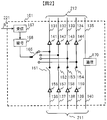
映像ソースと接続される中継装置101~106の構成例を図2に示す。図2においては、中継装置101が示されているが、102~106も同様の構成である。中継装置101は、映像ソースから映像データを入力する入力端子221と、ディジーチェイン接続用の入力端子211と出力端子212を持つ。入力端子211は、映像データを入力する4本のレーン136~139と、通信用のレーン140を有する。同様に、出力端子212は、映像データを出力する4本のレーン131~134と、通信用のレーン135を有する。
156~159は入力回路、151~154はスイッチ、141~144は出力回路、170は通信部である。167は受信部、168は暗号化部、165は出力選択部である。以下、図2の中継装置101の動作を説明する。
入力端子211から4本のレーン136~139に入力された映像データは、例えばシリアルデータの差動データであり、入力回路156~159でケーブル伝送中に波形劣化した信号からディジタルデータを再生する。スイッチ152~154がON状態であれば、それらのディジタルデータは出力回路142~144を通じてレーン132~134へ出力される。
一方、映像ソースから入力端子221へ入力された映像データは受信部167で受信後、コンテンツ保護等で必要な場合は暗号化部168で暗号化処理が施される。暗号化部168の出力データは、出力選択部165で出力回路141へ送られる。一方、入力回路156の出力はスイッチ151がオフになっているので、出力回路141は出力選択部165からの出力のみをレーン131へ出力する。
このように、出力端子212では、入力端子221に入力された映像ソースの映像データがレーン131から、入力端子211に入力されたレーン137~139の映像データがレーン132~134から出力される。
通信部170は、映像ソースから入力端子221に入力される映像データを出力端子212のどのレーンに出力するか、入力端子211に入力される各レーンの映像データを出力端子の各レーンに出力するかどうかを決めるために必要な情報を得るために、他の中継装置と交わすメッセージの送受信を行っている。
映像ソースと接続される中継装置101~106の他の構成例を図3に示す。図2と同様に、図3においては中継装置101が示されているが、102~106も同様の構成である。図2と同じ機能、構成となるものには同じ番号を付しており、その説明は省略する。
図3の中継装置は、図2の中継装置に対して、入力選択部166と符号復号部155、多重符号化部169が追加されている。図3において、入力端子211のレーン136から入力される映像データを入力回路156がディジタルデータに再生し、入力選択部166を通して符号復号部155へ映像データが伝えられる。
符号復号部155は、ケーブル伝送用に例えば8B/10B方式(8ビットのデータを10ビットのデータに変換して転送する方式)で符号化されていた映像データを復号する(コンテンツ保護などの暗号処理がかかっている場合、暗号復号は行わない)。符号復号部155からの暗号化された映像データと、暗号化部168からの暗号化された映像データとを、多重符号化部169がケーブル伝送用に適した多重化と符号化処理を施し、出力選択部165を介して伝送するレーンの出力回路に伝える。図3では、出力選択部165が選ぶ出力回路141が、出力端子212のレーン131へ出力する。
このように、図2ではレーン131が出力する映像データは入力端子221に入力される映像データのみであるが、図3では、入力端子211のレーン136に入力される映像データと共に出力できるので、レーンの有効活用ができる。2つの映像データを1レーンで送る場合、レーンの最大伝送能力を超えない映像フォーマットを各映像ソースが送るように設定するとよい。映像ソースが映像データ量を調整できない場合は、受信部167で映像フォーマット変換またはデータ量圧縮処理を施してもよい。映像入力端子211のレーン156のデータ量を削減する必要がある場合は、符号復号部155に加えて暗号復号も行ってから映像フォーマット変換またはデータ量圧縮処理を施した後に暗号化処理を行うとよい。
スイッチ151~154と入力選択部166、符号復号部155、多重符号化部169、出力選択部165から構成される映像データ合成部160は、入力端子211の入力映像データと入力端子221の入力映像データを合成する。映像データ合成部160は、入力端子221の映像データを1レーンへ出力する場合のみならず、1つの映像データを2本や4本など複数のレーンを用いて出力する場合であっても、同様な構成で実現できる。
また、図3の入力回路157~159と出力回路142~144との間に、ケーブル伝送用の符号復号部と再符号化部をそれぞれ追加してもよい。符号復号部と再符号化部を設けることにより、ケーブル伝送において生じたデータエラーを削減できる利点がある。
符号復号や再符号化に伴い、映像データの遅延が生じる場合がある。生じた遅延時間は、受信した映像データに付与されている遅延時間に加算して出力し、表示装置が接続された中継装置が映像データに付与されている遅延時間と表示装置の表示遅延時間を映像ソースが接続された中継装置へメッセージとして伝えることにより、映像ソースが表示装置の表示遅延時間を把握できる。複数の表示装置で同時表示させる場合は、表示遅延時間をそろえる必要がある。その場合は、映像ソースが各表示装置へ映像データ伝送遅延時間と表示遅延時間の合計値を指示するメッセージを送り、各表示装置がその表示遅延時間に合わせて表示を行えばよい。
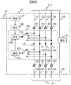
次に、表示装置と接続される中継装置107~110の構成例を図4に示す。図4においては、中継装置107が示されているが、108~110も同様の構成である。中継装置107は、ディジーチェイン接続用の入力端子215と出力端子216、表示装置へ映像データを出力する出力端子222を持つ。入力端子215は、映像データを入力する4本のレーン171~174と、通信用のレーン175を有する。同様に、出力端子216は、映像データを出力する4本のレーン176~179と、通信用のレーン180を有する。
181~184は入力回路、196~199は出力回路、195は通信部である。185と187は入力選択部、188と190は符号復号部、189と191は暗号復号部、192は2画面合成回路、193は送信部、185は映像データ取出し部である。以下、図4の中継装置203の動作を説明する。
入力端子215から4本のレーン171~174に入力された映像データは、例えばシリアルデータの差動データであり、入力回路181~184でケーブル伝送中に波形劣化した信号からディジタルデータを再生する。これらの再生されたディジタルデータを出力回路196~199が4本のレーン176~179へ出力される。
一方、入力選択部186と187が入力回路181~184の内、例えば入力回路181と182の出力を選択して、それぞれ符号復号部188と189へ入力する。符号復号部188と190はケーブル伝送用に符号化されたディジタルデータの符号復号を施し、暗号復号部189と191へ伝える。暗号復号部189と191はコンテンツ保護等を目的として施された暗号処理を復号して2画面合成回路192へ伝える。2画面合成部192は2つの映像データを合成する処理を行い、送信部193へ伝える。送信部193が出力端子222を通じて表示装置へ合成された映像データを出力する。なお、レーン171と172の2つのレーンを用いて映像データを伝送している場合は、2画面合成回路192は、2レーン分の映像データを1つの映像データとして構成しなおす機能を有するとよい。
このように、出力端子216には、入力端子215に入力された映像データをそのまま出力しているが、入力端子211に入力されたレーン171と172の映像データが出力端子222へ出力され、出力端子216で不要となる場合は、出力回路196と197の回路動作を止めるまたは電源供給を停止させて消費電力低減を目指してもよい。通信部195は、入力端子215の4本のレーン171~174に入力される映像データのどれを出力端子222と出力端子216の4本のレーン176~179に出力するかどうかを決めるために必要な情報を得るために、他の中継装置と交わすメッセージの送受信を行っている。
図4の映像データ取り出し部は、2レーン分の映像データを暗号復号部189や191へ出力して、出力端子222から表示装置へ送る例を示しているが、3レーンまたは4レーン全てから取り出す構成としてもよいし、複数の映像データが1レーンに含まれている場合は、そのうちの一部を取り出す構成としてもよい。
図5は、映像データ伝送ルートの一例を示す。例えば、中継装置101~106それぞれに接続される映像ソースがそれぞれFHD(Full HD, 1080p)、720p、4k2k、1080i、FHD、FHDの映像データを出力する場合を想定している。一方、中継装置107~110にそれぞれ接続される表示装置117~120がそれぞれFHD、720p、4k2k、FHDの映像データを表示できる場合を想定している。
図5では、映像ソース112~115が出力する映像データ692~696を中継装置102~中継装置105から中継装置107~110へ伝送し、表示装置117~120が表示する例を示している。中継装置101~110の間をディジーチェイン接続するケーブル121~129には、各ケーブル番号のセルの下段に示したレーン数を映像データ伝送に用いている。この映像データ伝送ルートの構築に必要な情報は中継装置間のメッセージ交信を通じて得られる。映像データ伝送ルート確保するメッセージ交信の一例を図6と図7を用いて説明する。
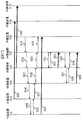
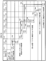
映像ソース113の映像データを表示装置119へ表示させる場合、映像ソース113に接続された中継装置103が、表示装置119に接続された中継装置109へ向けて映像伝送ルートを打診するメッセージを送る。中継装置間の通信路は隣接中継装置間の通信の為、中継装置103から中継装置109へのメッセージは間に入る中継装置104~108が順次転送し、メッセージ601~605として伝えられる。映像ソース113から表示装置119までのルートの途中に入る中継装置は、メッセージを中継する際に中継装置の持つ固有の名称またはアドレスを経路情報として追加し、順次転送することによって、メッセージ605を受信した中継装置109は、映像ソース113が接続された中継装置103から中継装置109までの通信ルートがわかる。
なお、図6と図7とでは中継装置106の記述を省略しているが、中継装置105と中継装置107の間に中継装置106が介在して、他の中継装置と同様にメッセージを中継している。以下の説明では中継装置106に関する説明を省略する。
中継装置109は、映像表示装置119の表示能力に関する情報(例えば、画素数が4k2k、ディスプレイサイズが70型という情報)と、中継装置109の受信能力に関する情報(中継装置109が単位時間当たりに受信可能なデータ量を示す情報で、例えば5.4Gbpsの受信能力を持つレーンを4レーン持つことを示す情報)、メッセージを返送する通信ルート情報を記載したメッセージ606を中継装置108に送る。
中継装置108は、自身の送信能力(中継装置108が単位時間当たりに送信可能なデータ量)と、メッセージ606に記述された中継装置109の受信能力に関する情報とから中継装置108と中継装置109との間で単位時間当たりに伝送可能なデータ量(以下、伝送能力と示す。)を判断する。この伝送能力を示す情報、その伝送能力のうち、現在使用中の伝送量(以下、使用中伝送能力と示す。)に関する情報、使用中伝送能力を使用している映像ソースに接続される中継装置(以下、伝送能力使用装置と示す。)の名前やアドレスに関する情報、及び中継装置108の受信能力に関する情報をメッセージ606に加えて生成したメッセージ607を、中継装置107へ送る。以下、同様に中継装置107~104が伝送能力に関する情報等を加えたメッセージ608~610を中継して、中継装置103に伝える。
この例では、中継装置103~109間において、4レーン各5.4Gbpsの伝送能力があり、かついずれのレーンも使われていない場合について説明する。中継装置103から中継装置104~109へ使用するレーンの情報や経由する中継装置の情報等を含むルート確保メッセージ(例えば、中継装置104~109の4レーン全て5.4Gbpsで使用する旨を記述した情報)611~615を伝送する。その後、中継装置103から中継装置109への4k2k@60Hzの映像データ691を伝送開始する。
なお、映像データ691に、使用するレーンの情報や経由する中継装置の情報等を含むルート確保情報が付加されていれば、メッセージ611~615は省略してもよい。また、ルート確保メッセージまたはルート確保情報を各中継装置が受信する前に、他の映像ソースからの映像データを伝送し始めたためにルート確保できない場合は、ルート確保できないことを示すエラーメッセージを、映像ソースと接続されている中継装置103へ返すとよい。
続いて、映像ソース115から表示装置120へFHD映像データを伝送する場合を説明する。中継装置105から中継装置107、108、109を経由して中継装置110へ映像伝送ルートを打診するメッセージ621~624が経路情報を追加されながら順次送られる。中継装置110は、映像表示装置120の表示能力に関する情報(例えば画素数がFHDのプロジェクタであることを示す情報)、中継装置の受信能力に関する情報、メッセージを返送する通信ルート情報を記載したメッセージ625を中継装置109へ送る。メッセージ606~610の送信と同様に、中継装置109~107が順次、伝送能力、使用中伝送能力、伝送能力使用装置、中継装置の受信能力に関する情報等を順次追加してメッセージ626~628を送信し、中継装置105がメッセージ628を受信する。
メッセージ628からは、中継装置107~中継装置109の間(図示していないが中継装置106も含む。以下同様。)で映像データを伝送する4レーン全てが中継装置103の出力する映像データ伝送に使われていることがわかる。但し、メッセージ621~628の交信をしないでも、その前に送信されたメッセージ613~615から、または中継装置105自身が4k2kの映像データ691を伝送していることから、4レーン全てが使用中であることがわかるので、メッセージ621の送信やメッセージ628の受信を待たずに、空レーンが無いと判断してもよい。
そこで、中継装置105は中継装置103へ、中継装置105~109間の伝送レーンの使用を要求するメッセージ631を中継装置104へ送り、中継装置104が中継装置103へメッセージ632を転送する。メッセージ631には、伝送レーンの使用の優先度を示す情報が含まれていてもよい。
中継装置103は、中継装置103による伝送レーンの使用と中継装置105による伝送レーンの使用とのどちらを優先させるかを判断する。この判断は、例えば中継装置103が持つ優先度を示す情報とメッセージ631、632に含まれる優先度を示す情報とに基づいて行われる。中継装置103が持つ優先度は、あらかじめ使用者が設定しておいてもよいし、中継装置103が映像ソース113から優先度情報を取得してもよい。
また、中継装置103が中継装置105からの伝送レーン使用要求を映像ソース113に伝え、その応答に応じてどちらを優先させるかを決めてもよい。
中継装置103による使用を優先させる場合は使用要求を拒否する情報を、中継装置105の使用を優先させる場合は、中継装置103自身が配信する映像データを伝送するレーンを例えば2本に減らすことを示す情報を、メッセージ633として中継装置104へ伝え、中継装置104がメッセージ634として中継装置105に伝える。
中継装置103が出力する映像データの使用レーン数を例えば2本に減らす場合は、その情報をメッセージ635~639として、順次中継装置104~中継装置109へ伝送される。メッセージ633とメッセージ634、メッセージ635と636は共通メッセージとして、メッセージ数を削減してもよい。
なお、中継装置103が映像データの配信を停止させる際は、伝送レーンの開放を示すメッセージを送ることによって、配信経路上の該当伝送レーンを開放させてもよい。また、例えば2秒以上など、所定時間映像データの配信が止まると、伝送レーンの開放を示すメッセージを受信しなくても該当伝送レーンを開放させるようにしてもよい。このように、該当伝送レーンを開放する条件を決めておくことで、伝送レーンを有効活用でき、さらに使用していない伝送レーンをより早く開放できるので、消費電力低減効果もある。
中継装置103は映像ソース113から出力される4k2k映像データを、例えば1/2に圧縮処理を行い、2レーンで伝送できる量の映像データ692を、中継装置103から中継装置109へ伝送する。各中継装置は、新たな映像データ692が来るまでは、以前の映像データ691を継続して送り続けることにより、表示装置119の表示画面が途切れることを防止してもよい。なお、メッセージ635~639に含まれる情報が映像データ692に付加されていれば、メッセージ635~639は省略してもよい。
中継装置103が映像データ伝送を2レーンに限定する決定をしたメッセージ634または、レーン確保メッセージ636を受信した中継装置105は、中継装置107~110へルート確保メッセージ641~644を送り、続いてFHD映像データ693を出力する。FHD映像データ693を受信した中継装置110は、接続された表示装置120へFHD映像データを送り、表示装置120がFHD映像を表示する。
尚、上記の例では中継装置103が使用するレーン数を減らすために圧縮処理を行ったが、圧縮処理を行う代わりに、映像ソース113の映像データを4k2kから例えばFHDへ解像度を変更することにより、レーン数を減らす場合も、同様である。
図7は、4k2k映像データ692とFHD映像データ693を伝送中に、他の映像データをさらに追加で伝送する場合を説明している。図6では、映像ソースが接続された中継装置から映像データ伝送の打診を示すメッセージを表示装置が接続された中継装置へ送信していたが、図7では表示装置が接続された中継装置から映像データ伝送の打診を示すメッセージを映像ソースが接続された中継装置へ出す場合を例にとる。
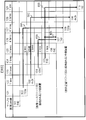
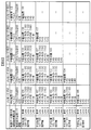
この映像表示装置が接続された中継装置から順次伝送される映像データ伝送の打診を示すメッセージ651~655は、図6の映像ソースが接続された中継装置から順次転送される打診メッセージに対する応答メッセージ(メッセージ606~610、625~628)と同様のメッセージとしてもよい。メッセージ651~655が持つ情報の一例を図8に示す。
例えば、中継装置108は、映像データ要求先が中継装置102であり、その映像データ伝送の優先度がレベル5であること、接続されている表示装置118の表示能力に関する情報(例えば1280x720画素数(いわゆる720p)を持つ32型サイズ)と中継装置108の受信能力に関する情報(例えば5.4Gbpsの受信能力を持つレーンを4レーン持つ)をメッセージ651として中継装置107に送る。
中継装置107は、自身の送信能力と、メッセージ651に記述された中継装置108の受信能力に関する情報とから中継装置107と中継装置108との間の伝送能力を判断する。この伝送能力を示す情報、使用中伝送能力、伝送能力使用装置の名前やアドレスに関する情報、及び中継装置107の受信能力に関する情報を、メッセージ651に加えたメッセージ652を中継装置106へ送る。図8に示したメッセージ652は、中継装置108の受信能力と中継装置107の送信能力が共に5.4Gbps、4レーンであるので、伝送能力も5.4Gbps、4レーンとなる。使用中伝送能力は4k2kを2レーン、FHDを1レーン、空きが1レーンである。伝送能力使用装置の名前やアドレスに関する情報は、中継装置103と中継装置105である。中継装置107の受信能力は、5.4Gbps、4レーンである。以下、同様に中継装置105~103がメッセージ653~655を中継して、中継装置102に伝える。
図6の応答メッセージ(メッセージ606~610、625~628)には映像ソースが接続される中継装置から映像表示装置が接続される中継装置までの経路情報が含まれていたが、図7の打診メッセージ(メッセージ651~655)には経路情報がないので、映像データの伝送方向と反対方向に伝送するとよい。すなわち、中継装置108がメッセージ651を中継装置107に伝送し、順次中継装置107~103がメッセージ652~655を伝送するとよい。もちろん、中継装置が転送するメッセージの内容を解析するなどして経路情報が得られている場合は、経路情報をメッセージに記述しておいてもよい。例えば、図8のメッセージ651において、中継装置107-105間の情報を記述する予定の領域が空欄になっているが、中継装置107の名称を記述しておき、各レーン情報を空欄(または情報なしを意味する“0”などの所定データ)にしておけば、経路情報であることがわかる。
表示装置118からの映像データの要求を示すメッセージを受信した中継装置102は、メッセージ655の情報から、中継装置102~108の間で5.4Gbpsの能力を有するレーン4が空いていると判断し、表示装置118にふさわしい720p映像をレーン4で伝送することを決め、レーン確保メッセージ656を中継装置103へ送る。中継装置103~中継装置107がその情報をメッセージ657~660で順次伝送し、表示装置に接続される中継装置108へ伝えられる。続いて、中継装置102が映像ソース112の映像データ694を中継装置103~107を経由して中継装置108へ伝送される。
次に、表示装置117が、中継装置105から中継装置110へ伝送中の映像データ693を要求する場合について述べる。表示装置が接続される中継装置107が、中継装置105へ映像データを要求するメッセージ661を送り、それを受信した中継装置105が、伝送中の映像データ693を中継装置107が抽出して表示装置117で表示を許可するメッセージ662を中継装置107へ返す。中継装置107は、映像データ693の映像データを映像データ695として抽出して表示装置117へ送り、表示させる。表示装置117と120とが要求する映像フォーマットが異なる場合は、別映像データとして並列に送ってもよいし、両表示装置が表示可能な共通映像フォーマットに切換えて、映像データ伝送レーンンを共用してもよい。
次に、表示装置117が映像ソース115のFHD映像データ695に加えて映像ソース114の1080i映像データ696を同時表示させる場合を説明する。表示装置が接続された中継装置107が、映像データを要求するメッセージ666を中継装置105に送り、中継装置105がその情報をメッセージ667として、映像ソース114に接続される中継装置104へ伝送する。
中継装置104は、レーン4が5.4Gbps伝送能力に対して、720p映像と1080i映像がそれぞれ2.7Gbpsの割り当てで同時伝送できると判断し、映像ソース114の1080i映像データ696を、映像データ694と共にレーン4で送ることを示すメッセージ668を中継装置105へ送る。中継装置105は、その情報を表示装置117が接続される中継装置107へ送られる。続いて、中継装置104が映像データ696を中継装置107に送る。
中継装置107が、例えば、図4で示した中継装置であれば、スイッチ186と187がそれぞれ映像データを抽出し、符号復号部188と190で伝送符号を復号化する。続いて、暗号復号部189と191がコンテンツ保護用に暗号を復号した上で、映像合成部192で1画面に合成される。合成後の映像信号は、送信部から出力され、例えば、2映像データを合成した映像が得られる。
以上で述べてきたように、映像ソースがつながる中継装置と表示装置がつながる中継装置をディジーチェイン接続した上で、映像データの優先度や画質、経路情報などの情報を相互にメッセージ交換する仕組みとを導入し、複数映像データの同時伝送と映像データ伝送路の確保をスムースに行うことができる利点がある。
実施例1では、中継装置の入出力端子は、映像データの伝送方向があらかじめ決まっている場合を説明した。実施例2では、中継装置の入出力端子は、映像データの伝送方向を切換えできる構成とした例を説明する。映像データの伝送方向を切換えできる構成とすることで、ディジーチェイン用の端子の入出力方向を気にすることなく機器を接続できるので、ケーブル接続における煩わしさやミスを減らし、接続に要する時間を低減できる。さらに、映像ソースや表示装置のディジーチェイン接続順番を自由に決めることができる。
図9は映像送受信システム構成の一例であって、図1と表示装置119とPC112の位置を入れ換えている。図1の中継装置101~110とケーブル121~129に代えて、中継する映像データの方向を反転できる中継装置301~310とケーブル321~329を用いている。一般に、両端子間を電気配線で単純接続したケーブル121~129は双方向伝送ケーブルとして使えることができるが、イコライザ内蔵ケーブルや光変換ケーブルはデータ伝送方向が単方向に決まっていることがある。このような単方向ケーブルは、信号線の結線やピン数、形状、識別信号を付与して自動検出し、実施例1の動作と実施例2の動作を切換えるようにしてもよい。単方向と双方向の中継装置が混在する場合も、メッセージの交信で実施例1と2の動作を切換えるとよい。
このような切換え状況を、管理用PCとして例えばPC116に閲覧表示させるか、表示装置にOSD表示させると、ユーザによる使用状況把握が簡単にできる利点がある。また、ケーブルの接続方向誤りや、接続端子の誤り、ケーブル接続変更によるケーブル内の映像データ伝送の最大伝送量を下げて信頼性を向上させるユーザ補助情報を表示させて使い勝手を向上させることもできる。
ユーザへの警告メッセージや推奨メッセージの表示例を図14に示す。251が表示画面あり、システム全体の接続図が表示される。この例では、中継装置は各映像ソースや表示装置に内蔵されているように示している。252は、単方向ケーブルを誤った方向に接続した場合に、ケーブルの向きを合わせるように警告するメッセージである。253は、表示装置の端子にケーブルを差し間違えた場合に、差しなおしを要求する警告メッセージである。254は、装置間のケーブル接続を差し替えると、映像データ転送レートを下げられる場合の推奨メッセージである。
図10は、映像ソースに接続される中継装置の一例を示しており、図3の中継装置の入出力を双方向化したものである。同じ機能を持つものには同じ番号を付与しているので、説明は省略する。図10においては、中継装置301が示されているが、301~306も同様の構成である。また、360は160と同様に、映像データ合成部ともいう。
端子213を入力、端子214を出力とする場合、入力回路356~359と出力回路341~344を動作させ、入力回路351~354と出力回路346~349は待機状態として出力を高インピーダンス化させる。逆に、端子214を入力、端子213を出力とする場合、入力回路351~354と出力回路346~349を動作させ、入力回路356~359と出力回路341~344は待機状態として出力を高インピーダンス化させる。スイッチ361~364は、図3のスイッチ151~154と同様に、入力端子に入力された映像データと、スイッチ165が選択した映像データのいずれかを選んで出力回路へ渡すものである。
入出力端子の映像データ伝送方向は、中継装置全体で伝送方向を決めてもよいし、レーン毎に伝送方向を決めてもよい。さらに、同一レーンの両端子とも出力端子として映像ソースの映像データを共に出力できるようにしてもよい。
図11は、表示装置に接続される中継装置の一例を示しており、図4の中継装置の入出力を双方向化したものである。同じ機能を持つものには同じ番号を付与しているので、説明は省略する。図11においては、中継装置307が示されているが、307~310も同様の構成である。
端子217を入力、端子218を出力とする場合、入力回路381~384と出力回路396~399を動作させ、入力回路386~389と出力回路391~394は待機状態として出力を高インピーダンス化させる。逆に、端子218を入力、端子217を出力とする場合、入力回路386~389と出力回路391~394を動作させ、入力回路381~384と出力回路396~399は待機状態として出力を高インピーダンス化させる。
入出力端子の映像データ伝送方向は、中継装置全体で伝送方向を決めてもよいし、レーン毎に伝送方向を決めてもよい。さらに、同一レーンの両端子とも入力端子として表示装置へ映像データを出力できるようにしてもよい。
図12は、映像データの伝送ルートの一例を示す。図5と同様に、映像データ791~795の伝送を例にとっているが、映像データを双方向伝送でき、かつ、表示装置119とPC112の位置を入れ換えていることによって、映像ソース113の4k2k映像は圧縮することなく、データ欠落の生じない4レーンで伝送できる。また、システム全体におけるケーブルの映像データ伝送量も抑制できることから、データ伝送の信頼性を向上させ、さらには、データ伝送に必要な消費電力を下げられる利点もある。
図13は、図12の映像伝送ルートを形成するためのメッセージ交信の一例である。実施例1におけるメッセージ交信を示した図6と図7に比べてメッセージ交信量も減らすことができる。図6と同様に、映像ソース113から表示装置319へ4k2k映像データを転送する例から始める。
映像ソース113が接続された中継装置303から表示装置319が接続された中継装置309へ映像伝送ルートを打診するメッセージ701を送る。図6では、各中継装置の映像伝送方向が一定方向であったため、映像ソース側中継装置は表示装置側中継装置へ、表示装置側中継装置は映像ソース側中継装置へ打診メッセージを送ればよかったが、実施例2では映像伝送方向が双方向の為、この原則が使えない。よって、中継装置はあらかじめディジーチェイン接続された各中継装置に対して接続先が表示装置か、映像ソースであるかなどを問い合わせるメッセージを送信し、各中継装置の接続先を把握しておくとよい。
中継装置情報が不明の場合は、打診メッセージを中継装置309宛だけでなく、中継装置304へも送るとよい。打診先の表示装置名称などを記載しておくと、該当表示装置から応答メッセージが返ってくるのを待てば、経路情報を入手できる。該当表示装置がない場合は、応答メッセージが返ってこないので、所定時間、例えば1秒待って該当表示装置なしと判断してもよい。打診先を全ての表示装置、あるいは所定の解像度、例えばFHD以上の解像度を持つ表示装置や、所定の画面サイズを持つ表示装置のように条件をつけ、その条件に合った表示装置が接続されている中継装置からの応答メッセージを待ってもよい。
図13の例では、打診メッセージ701を受信した中継装置309が、接続されている表示装置319の表示能力に関する情報(例えば4k2k表示)や中継装置309の受信能力(5.4Gbpsを4レーン受信可)に関する情報を記載した応答メッセージ703を、中継装置303へ返信する。応答メッセージ703を受信した中継装置303は、映像データ伝送ルート確保メッセージ703を中継装置309へ送信後、5.4Gbps伝送路を4レーン用いた映像データ791を中継装置へ伝送開始する。
続いて、映像ソース315から表示装置320への映像データ伝送について説明する。図6の打診および応答メッセージ621~628と同様に、打診および応答メッセージ711~718が交信される。図6のケースでは、4k2k映像データ伝送の為に全レーンが使用済みせあったが、図13の例では中継装置305~310の間で映像データ伝送は始まっていない。このため、中継装置305は、1レーンを使ったFHD映像データ伝送ルート確保メッセージ719を中継装置307へ送り、順次中継装置307、308、302がメッセージ720~722を送信し、中継装置310へ伝える。中継装置305は確保した伝送ルートへ、FHD映像データ792を出力する。
次に、表示装置118が映像ソース112の720p映像データを要求する例を説明する。表示装置118に接続された中継装置308が、映像データ要求メッセージ731を映像ソースが接続された中継装置302へ送信する。実施例2では、映像データ伝送方向が切換えできるので、中継装置302がどの位置にあるかわからない場合は、中継装置307にも映像データ要求メッセージ731を送り、中継装置302からの応答メッセージを待つことになる。この時、中継装置302を指定するのではなく、720pのコンテンツを持つ映像ソースや、コンテンツの番組名やジャンル情報を持つ映像ソース、モバイル機器である映像ソースといった条件で映像ソースを探索してもよい。
映像データ要求メッセージを受信した中継装置302は、1レーンを使った720P映像データ伝送ルート確保メッセージ731を中継装置308へ送信し、映像ソース112から得た720p映像データ793を中継装置308に送る。
同様に、表示装置117が映像ソース115のFHD映像データを要求する例を説明する。表示装置117が接続された中継装置307が、映像データ要求メッセージ736を中継装置305に送る。該メッセージ736を受信した中継装置は、既に出力している映像データ792から抽出する許可を、FHD映像データ伝送ルート確保メッセージ737として中継装置307へ送る。中継装置307は、映像データ792から抽出する映像データ794を表示装置117へ送る。映像データ794伝送により、誤って映像データ792の伝送を止めてしまわないように、映像データストリーム中に、複数の受信先である中継装置310と中継装置307を双方の情報を入れておくとよい。また、映像データ792の伝送を止めてしまうアクシデント対策として、映像データ伝送能力に余裕があるので、映像データ794を、映像データ792と独立したレーンを用いて伝送してもよい。
続いて、表示装置117が映像ソース115に加えて映像ソース224の映像データも同時に要求する例を説明する。表示装置117が接続された中継装置307が、映像データ要求メッセージ741を中継装置305へ送り、中継装置305が自身の受信能力情報等を追加したメッセージ742を中継装置304へ伝送する。映像ソース114が接続された中継装置304が1080i映像データの伝送ルートを確保する伝送ルート確保メッセージ743を中継装置305へ、中継装置305はルート確保メッセージ744を中継装置307へ送る。中継装置304は、ルート確保メッセージ743を送信後、1080i映像データ795を中継装置307へ伝送する。
以上、述べてきたように、中継装置を双方向伝送化することにより、映像ソースと表示装置の配置のしかたに自由度が生まれるので使い勝手が向上する。さらには映像データ伝送路の最大伝送容量を下げることも可能となり、映像データ伝送用の消費電力低減、映像データ伝送の信頼性向上、電磁波ノイズを低減できる効果がある。
以上の実施例では、映像データを最初に送り出す中継装置が伝送ルート確保の打診メッセージと伝送ルート指定のメッセージを出し始め、映像データを最終的に受信する中継装置が応答メッセージを出し始める例を説明したが、逆に映像データを最終的に受信する中継装置が伝送ルート確保の打診メッセージと伝送ルート指定のメッセージを出し始め、映像データを最初に送り出す中継装置が応答メッセージを出し始めてもよい。中継装置が応答メッセージまたは打診メッセージを転送する際に、各メッセージを受信する端子または転送する端子の送受信能力とメッセージ転送時点における使用中伝送能力の情報を追加して転送することにより、最終的に各メッセージを受信する中継装置が、各中継装置のディジーチェイン接続端子の伝送能力とその使用状況を把握することができる。すなわち、上記実施例と同様に、通信路を決定して、所望の通信路を確保することができる。
101~120、201~205、301~310 中継装置
111、112、116 PC
113 Player
114 STB
115 書画カメラ
117~120 表示装置
121~129、321~329 ケーブル
131~134、196~199、341~344、346~349、391~394、396~399 出力回路
151~154 スイッチ
155、188、190 符号復号部
156~159、181~184、351~354、356~359、381~384、386~389 入力回路
160、360 映像データ合成部
165、351~364 出力選択部
166,186、187 入力選択部
167 映像データ受信部
168 暗号化部
169 多重符号化部
170、195 通信部
185 映像データ取出し部
189、191 暗号復号部
192 2画面合成部
193 送信部
601~618、621~628、631~639、641~644、651~662、667~669、701~703、711~722、731~733、736、737、741~744 メッセージ
691~696、791~795 映像データ
111、112、116 PC
113 Player
114 STB
115 書画カメラ
117~120 表示装置
121~129、321~329 ケーブル
131~134、196~199、341~344、346~349、391~394、396~399 出力回路
151~154 スイッチ
155、188、190 符号復号部
156~159、181~184、351~354、356~359、381~384、386~389 入力回路
160、360 映像データ合成部
165、351~364 出力選択部
166,186、187 入力選択部
167 映像データ受信部
168 暗号化部
169 多重符号化部
170、195 通信部
185 映像データ取出し部
189、191 暗号復号部
192 2画面合成部
193 送信部
601~618、621~628、631~639、641~644、651~662、667~669、701~703、711~722、731~733、736、737、741~744 メッセージ
691~696、791~795 映像データ
Claims (10)
- 映像データを入力可能な入力部及び映像データを出力可能な出力部を有する中継装置であって、
前記入力部に入力されたメッセージに、前記中継装置が伝送可能な映像データの量に関する情報及び当該中継装置が伝送している映像データの量に関する情報を追加し、前記出力部から出力することを特徴とする中継装置。 - 請求項1の中継装置であって、
映像データを送信する他の機器に対して送信する映像データの伝送量の削減を要求するメッセージを送信することを特徴とする中継装置。 - 請求項2の中継装置であって、
前記映像データの伝送量の削減を要求するメッセージと共に、映像データ配信の優先度に関する情報を送信することを特徴とする中継装置。 - 請求項1~3のいずれかの中継装置であって、
映像ソースから映像データを受信する受信部と、
前記受信部で受信した映像データと、前記入力部に入力された映像データとを合成する映像合成部と、を有し、
前記映像合成部で合成された映像データを前記出力部から出力することを特徴とする中継装置。 - 請求項1~3のいずれかの中継装置であって、
映像ソースから映像データを受信する受信部を有し、
前記入力部及び出力部は映像データを伝送する複数の伝送レーンを有し、
前記受信部で受信した映像データと、前記入力部に入力された映像データとを異なる伝送レーンで伝送することを特徴とする中継装置。 - 請求項4または5の中継装置であって、
前記受信部で受信した映像データを暗号化する暗号化部を有し、
前記入力部に入力された映像データに施された暗号化処理を復号しないことを特徴とする中継装置。 - 請求項1の中継装置であって、
前記入力部に入力された映像データを表示する表示装置を有することを特徴とする中継装置。 - 請求項1の中継装置であって、
前記中継装置を含む複数の装置の接続構成に関する情報を出力することを特徴とする中継装置。 - 請求項8の中継装置であって、
前記接続構成に関する情報は、当該接続構成におけるケーブルの接続に関する情報を含むことを特徴とする中継装置。 - 映像データを入力可能な入力部及び映像データを出力可能な出力部を有する中継装置における送受信方法であって、
前記入力部にメッセージを入力するステップと、
前記入力部に入力したメッセージに、前記中継装置が伝送可能な映像データの量に関する情報及び当該中継装置が伝送している映像データの量に関する情報を追加するステップと、
追加されたメッセージを前記出力部から出力するステップと、を有することを特徴とする送受信方法。
Priority Applications (1)
| Application Number | Priority Date | Filing Date | Title |
|---|---|---|---|
| PCT/JP2012/077825 WO2014068630A1 (ja) | 2012-10-29 | 2012-10-29 | 中継装置および送受信方法 |
Applications Claiming Priority (1)
| Application Number | Priority Date | Filing Date | Title |
|---|---|---|---|
| PCT/JP2012/077825 WO2014068630A1 (ja) | 2012-10-29 | 2012-10-29 | 中継装置および送受信方法 |
Publications (1)
| Publication Number | Publication Date |
|---|---|
| WO2014068630A1 true WO2014068630A1 (ja) | 2014-05-08 |
Family
ID=50626611
Family Applications (1)
| Application Number | Title | Priority Date | Filing Date |
|---|---|---|---|
| PCT/JP2012/077825 Ceased WO2014068630A1 (ja) | 2012-10-29 | 2012-10-29 | 中継装置および送受信方法 |
Country Status (1)
| Country | Link |
|---|---|
| WO (1) | WO2014068630A1 (ja) |
Cited By (2)
| Publication number | Priority date | Publication date | Assignee | Title |
|---|---|---|---|---|
| GB2569808A (en) * | 2017-12-22 | 2019-07-03 | Canon Kk | Transmission method, communication device and communication network |
| WO2024114433A1 (zh) * | 2022-11-30 | 2024-06-06 | 苏州元脑智能科技有限公司 | 视频流加密的配置信息同步的方法、装置、设备及介质 |
Citations (6)
| Publication number | Priority date | Publication date | Assignee | Title |
|---|---|---|---|---|
| US5574951A (en) * | 1993-03-17 | 1996-11-12 | Unisys Corporation | System for providing a time division random access including a high speed unidirectional bus and a plurality of function cards connected in a daisy chain |
| JP2002171268A (ja) * | 2000-11-30 | 2002-06-14 | Fujitsu Ltd | リニア又はリングネットワークにおける伝送方法及び装置 |
| JP2002217886A (ja) * | 2001-01-16 | 2002-08-02 | Sony Corp | 電子機器及び信号伝送方法 |
| JP2004522379A (ja) * | 2001-07-16 | 2004-07-22 | エーロジックス カンパニー リミテッド | デイジチェーン方式を利用した映像監視システム |
| JP2005050304A (ja) * | 2003-05-01 | 2005-02-24 | Genesis Microchip Inc | パケット式ビデオディスプレイインタフェース及びその使用方法 |
| JP2011524992A (ja) * | 2008-05-06 | 2011-09-08 | インテグレーテッド・デバイス・テクノロジー・インコーポレーテッド | ビデオディスプレイデータのデイジーチェイン方式のシリアル配信の能力を有するシステム |
-
2012
- 2012-10-29 WO PCT/JP2012/077825 patent/WO2014068630A1/ja not_active Ceased
Patent Citations (6)
| Publication number | Priority date | Publication date | Assignee | Title |
|---|---|---|---|---|
| US5574951A (en) * | 1993-03-17 | 1996-11-12 | Unisys Corporation | System for providing a time division random access including a high speed unidirectional bus and a plurality of function cards connected in a daisy chain |
| JP2002171268A (ja) * | 2000-11-30 | 2002-06-14 | Fujitsu Ltd | リニア又はリングネットワークにおける伝送方法及び装置 |
| JP2002217886A (ja) * | 2001-01-16 | 2002-08-02 | Sony Corp | 電子機器及び信号伝送方法 |
| JP2004522379A (ja) * | 2001-07-16 | 2004-07-22 | エーロジックス カンパニー リミテッド | デイジチェーン方式を利用した映像監視システム |
| JP2005050304A (ja) * | 2003-05-01 | 2005-02-24 | Genesis Microchip Inc | パケット式ビデオディスプレイインタフェース及びその使用方法 |
| JP2011524992A (ja) * | 2008-05-06 | 2011-09-08 | インテグレーテッド・デバイス・テクノロジー・インコーポレーテッド | ビデオディスプレイデータのデイジーチェイン方式のシリアル配信の能力を有するシステム |
Cited By (3)
| Publication number | Priority date | Publication date | Assignee | Title |
|---|---|---|---|---|
| GB2569808A (en) * | 2017-12-22 | 2019-07-03 | Canon Kk | Transmission method, communication device and communication network |
| GB2569808B (en) * | 2017-12-22 | 2020-04-29 | Canon Kk | Transmission method, communication device and communication network |
| WO2024114433A1 (zh) * | 2022-11-30 | 2024-06-06 | 苏州元脑智能科技有限公司 | 视频流加密的配置信息同步的方法、装置、设备及介质 |
Similar Documents
| Publication | Publication Date | Title |
|---|---|---|
| EP1988541B1 (en) | Data receiver, data transmitter, and information processing method and computer program relating to said data receiver and transmitter | |
| EP2178295B1 (en) | Display system and display apparatus | |
| JP5460530B2 (ja) | 表示システム、表示装置、及び中継装置 | |
| CN101448122B (zh) | 显示装置和图像设备 | |
| JP4772908B2 (ja) | 通信装置 | |
| EP2048883A1 (en) | Display device and display system | |
| CN104540008B (zh) | 影像设备 | |
| KR101891147B1 (ko) | 에이치디엠아이 신호로 방송 수신기의 듀얼 디스플레이를 위한 휴대용 단말기의 장치 및 방법 | |
| JP2009278262A (ja) | 中継装置、および中継方法 | |
| KR20100106567A (ko) | 모바일 고화질 멀티미디어 인터페이스를 생성하여 용이하게 하기 위한 방법과 장치와 시스템 | |
| US12273652B2 (en) | Transmission method, apparatus, and system | |
| JP5645370B2 (ja) | 映像機器 | |
| JP2009232432A (ja) | ハイビジョントランシーバ | |
| WO2014068630A1 (ja) | 中継装置および送受信方法 | |
| JP2011155640A (ja) | 立体映像再生装置 | |
| JP2011114353A (ja) | ソース装置用アダプタ装置、ソース装置用アダプタ装置の制御方法、シンク装置用アダプタ装置、シンク装置用アダプタ装置の制御方法 | |
| JP4792543B2 (ja) | ディジタル信号記録再生装置、および、ディジタル信号記録再生方法 | |
| JP2012060205A (ja) | 表示システム、表示装置、及び中継装置 | |
| KR20130051711A (ko) | Mhl 복합 장치 및 모드 전환을 위한 방법 | |
| JP2012138933A (ja) | 通信システム | |
| JP2011176896A (ja) | 通信装置および通信装置における制御方法 | |
| JP4940279B2 (ja) | 中継装置 | |
| JP5698945B2 (ja) | 表示装置及び信号処理方法 | |
| WO2019044232A1 (ja) | 画像信号供給装置、表示システム、画像信号供給方法、制御プログラム及び記録媒体 | |
| JP4920112B2 (ja) | 信号出力装置、および、信号出力方法 |
Legal Events
| Date | Code | Title | Description |
|---|---|---|---|
| 121 | Ep: the epo has been informed by wipo that ep was designated in this application |
Ref document number: 12887349 Country of ref document: EP Kind code of ref document: A1 |
|
| NENP | Non-entry into the national phase |
Ref country code: DE |
|
| 122 | Ep: pct application non-entry in european phase |
Ref document number: 12887349 Country of ref document: EP Kind code of ref document: A1 |
|
| NENP | Non-entry into the national phase |
Ref country code: JP |