WO2014064915A1 - Av機器 - Google Patents
Av機器 Download PDFInfo
- Publication number
- WO2014064915A1 WO2014064915A1 PCT/JP2013/006203 JP2013006203W WO2014064915A1 WO 2014064915 A1 WO2014064915 A1 WO 2014064915A1 JP 2013006203 W JP2013006203 W JP 2013006203W WO 2014064915 A1 WO2014064915 A1 WO 2014064915A1
- Authority
- WO
- WIPO (PCT)
- Prior art keywords
- power
- control signal
- liquid crystal
- wireless communication
- supply
- Prior art date
- Legal status (The legal status is an assumption and is not a legal conclusion. Google has not performed a legal analysis and makes no representation as to the accuracy of the status listed.)
- Ceased
Links
Images



Classifications
-
- H—ELECTRICITY
- H04—ELECTRIC COMMUNICATION TECHNIQUE
- H04N—PICTORIAL COMMUNICATION, e.g. TELEVISION
- H04N21/00—Selective content distribution, e.g. interactive television or video on demand [VOD]
- H04N21/40—Client devices specifically adapted for the reception of or interaction with content, e.g. set-top-box [STB]; Operations thereof
- H04N21/41—Structure of client; Structure of client peripherals
- H04N21/4104—Peripherals receiving signals from specially adapted client devices
- H04N21/4122—Peripherals receiving signals from specially adapted client devices additional display device, e.g. video projector
-
- H—ELECTRICITY
- H04—ELECTRIC COMMUNICATION TECHNIQUE
- H04N—PICTORIAL COMMUNICATION, e.g. TELEVISION
- H04N21/00—Selective content distribution, e.g. interactive television or video on demand [VOD]
- H04N21/40—Client devices specifically adapted for the reception of or interaction with content, e.g. set-top-box [STB]; Operations thereof
- H04N21/41—Structure of client; Structure of client peripherals
- H04N21/4104—Peripherals receiving signals from specially adapted client devices
- H04N21/4131—Peripherals receiving signals from specially adapted client devices home appliance, e.g. lighting, air conditioning system, metering devices
Definitions
- the present invention relates to an AV device such as a set top box or a liquid crystal display device in which a video / audio signal is transmitted / received by wireless communication.
- control signals are transmitted by wireless communication so that the power on / off is linked between the set top box and the display device.
- the standby power tends to increase because the wireless communication needs to be in an operating state even when the power is turned off. Therefore, a first wireless transmission path for transmitting and receiving video signals and a second wireless transmission path for transmitting and receiving control signals for the user interface are provided, and only the second wireless transmission path can communicate in the standby state.
- a technique for reducing standby power has been proposed (see, for example, Patent Document 1).
- the present invention has been made in view of this point, and an object of the present invention is to make it possible to greatly reduce standby power while achieving convenience by linking the power ON / OFF of an AV device.
- the first invention is An AV device capable of transmitting and receiving video and audio signals by wireless communication with other AV devices, A wireless communication unit for wirelessly communicating video and audio signals; A power supply for supplying power to at least the wireless communication unit; A power switch for operating or stopping the power supply; A power control signal wiring for inputting a power control signal for turning on / off the power switch from the outside and a power control signal for turning on / off a power switch of another AV device in conjunction with the power switch are output to the outside. At least one of the power control signal wires, It is provided with.
- the AV device is controlled in a standby state or an operating state in conjunction with other AV devices, thereby improving convenience, and in the standby state, the wireless communication unit with relatively high power consumption is stopped and the standby is performed. Power consumption in the state can be reduced.
- the second invention is The AV device of the first invention,
- the power control signal is a signal input to a control terminal of the power switch.
- the power switch since the power switch is directly controlled by the power control signal, the power switch can be controlled without consuming any power particularly in the standby state.
- the third invention is The AV device of the first invention, Furthermore, a wired communication device is provided to supply power even when the power switch is off,
- the power control signal is a signal transmitted / received between the communication device and a communication device of another AV device.
- the wireless communication unit is stopped and the AV communication device is controlled to be in a standby state or an operating state by a wired communication device with relatively low power consumption. Power consumption can be reduced.
- the fourth invention is: Any one AV apparatus from the first invention to the third invention,
- the power control signal wiring is provided to be connectable to a signal transmission wiring provided in a power outlet or a power strip.
- each AV device it is easy to link each AV device by connecting the power control signal wiring to the signal transmission wiring provided on the power plug or power strip when the power plug of each AV device is inserted into the power outlet or power strip. Can be.
- the fifth invention is: An AV device according to a third invention,
- the communication device is configured to perform power line communication.
- the power control signal wiring may be configured to be connected to a cable having two or less conducting wires.
- the standby power can be greatly reduced while the convenience of the AV device is achieved.
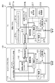
- FIG. 1 is a block diagram illustrating a configuration of an AV system according to a first embodiment.
- 6 is a block diagram illustrating a configuration of an AV system according to Embodiment 2.
- FIG. It is a block diagram which shows the structure of the AV system of Embodiment 3.
- FIG. 10 is a block diagram illustrating a configuration of an AV system according to a fourth embodiment. It is a table
- the set-top box 101 includes a tuner / input / output circuit 111, a video / audio controller 112, a wireless communication unit 113, a main power supply 114, a sub power supply 115, and a power switch 116. Yes.
- the liquid crystal display device 201 includes a liquid crystal display unit 211 including a liquid crystal panel 211a, a liquid crystal timing controller 211b, a backlight unit 211c, and a backlight controller 211d, a wireless communication unit 213, a main power source 214, and a sub power source 215. , A power switch 216, an LED display unit 217, and a remote control receiving unit 218.
- the tuner / input / output circuit 111 of the set-top box 101 is a video / audio signal input via television broadcasting, HDMI (High-Definition Multimedia Interface, registered trademark), LAN (Local Area Network), analog signal interface, or the like. Is supposed to receive.
- the audio / video controller 112 performs processing such as encoding and decoding of audio / video signals, for example.
- the wireless communication unit 113 wirelessly communicates video and audio signals, control signals, and the like with the wireless communication unit 213 of the liquid crystal display device 201.
- the communication method is not particularly limited, and various methods such as WiFi (wireless (fidelity, registered trademark), WHDI (Wireless Digital Interface) (both 5 GHz band), wirelessHD (60 GHz band), and the like can be used.
- the main power supply 114 has a power capacity required when the set-top box 101 is used for normal television broadcast viewing, etc., and enters the operating state when the power switch 116 is turned on. In addition, power is supplied to the video / audio controller 112, the wireless communication unit 113, and the like.
- the sub power source 115 has a power capacity required when the set-top box 101 is in a standby state (standby state), and regardless of the operation of the power switch 116, that is, when the power switch 116 is in a standby state.
- electric power is supplied to a portion of the tuner / input / output circuit 111 according to necessity through a path indicated by a broken line in FIG.
- the tuner portion is normally kept in an operating state in order to acquire program information, update information, and the like.
- the power switch 116 (for example, a relay) is output from the remote control receiver 218 of the liquid crystal display device 201 and sent via the power control signal wiring, and is controlled to be turned on and off according to the power control signal input to the control terminal.
- the power supply 114 is set to an operating state or a stopped state. Since the power control signal only needs to turn the power switch 116 on and off, a logic signal such as TTL can be used.
- a wiring cable between the set top box 101 and the liquid crystal display device 201 a thin cable that is relatively easy to route with one line can be used when two lines or both have a common ground.
- An amplifier may be provided in the power supply control signal transmission path.
- the liquid crystal panel 211a of the liquid crystal display device 201 displays an image signal output from the liquid crystal timing controller 211b and an image corresponding to the timing signal.
- the liquid crystal timing controller 211b outputs the image signal and the timing signal based on the video / audio signal received from the set top box 101 via the wireless communication unit 213.
- the backlight unit 211c emits backlight light from the back surface of the liquid crystal panel 211a.
- the backlight controller 211d controls the amount of light emitted from the backlight unit 211c.
- the wireless communication unit 213 wirelessly communicates video / audio signals, control signals, and the like with the wireless communication unit 113 of the set top box 101.
- the main power source 214 has a power capacity required when the liquid crystal display device 201 is used for normal television broadcast viewing, etc., and enters the operating state when the power switch 216 is turned on. Power is supplied to the light controller 211d, the wireless communication unit 213, and the like. Although not shown in FIG. 1, for example, when an audio output circuit, a speaker, and the like are provided, electric power is also supplied to these portions from the main power source 214.
- the sub power source 215 has a power capacity required when the liquid crystal display device 201 is in a standby state.
- the sub power source 215 does not depend on the operation of the power switch 216, that is, when the power switch 216 is in a standby state where the power switch 216 is turned off. Electric power is supplied to the LED display unit 217 and the remote control receiving unit 218 via a path indicated by a broken line.
- the power switch 216 is turned on / off according to a power control signal output from the remote control receiver 218, and the main power supply 214 is activated or stopped. It is supposed to be.
- the LED display unit 217 displays that the liquid crystal display device 201 is in a standby state.
- the remote control receiving unit 218 receives a power on / off operation signal from a remote controller (not shown), for example, by infrared communication.
- the power switches 116 and 216 are turned off, the main power sources 114 and 214 are stopped, and power consumption by the wireless communication units 113 and 213 is also reduced. It is suppressed.
- the tuner / input / output circuit 111 of the set-top box 101, the LED display unit 217 and the remote control reception unit 218 of the liquid crystal display 201 are supplied with relatively small power from the sub power sources 115 and 215 as necessary. And kept in operation. That is, since the wireless communication units 113 and 213 having relatively large power consumption are stopped, the power capacity of the sub power sources 115 and 215 can be set to be relatively small, and power consumption can be reduced in the standby state. .
- the remote control receiving unit 218 of the liquid crystal display device 201 receives a power-on operation signal from the remote controller, the remote control receiving unit 218 outputs a power control signal, the power switch 216 is turned on, and the power control is performed.
- the signal is sent to the set top box 101 via the power control signal wiring, and the power switch 116 is also turned on.
- the main power supplies 114 and 214 are connected to the power outlet in both the set-top box 101 and the liquid crystal display device 201, and the power is supplied to the respective units and the power supply is turned on.
- the wireless communication units 113 and 213 can also communicate with each other such as a video / audio signal, and normal content can be viewed on the liquid crystal display device 201.
- a power control signal is output from the remote control receiver 218 provided in the liquid crystal display device 201 and the power switch 116 of the set top box 101 is turned on and off.
- a power supply control signal may be output from a remote control receiver provided on the set top box 101 so that the power switch 216 of the liquid crystal display device 201 is turned on / off.
- both the power switches 116 and 216 of the set top box 101 and the liquid crystal display device 201 may be turned on / off by a power control signal output from a remote control receiving unit or the like provided in another device.
- the power switches may be mutually controlled between the set top box 101 and the liquid crystal display device 201 or between other devices.
- the example in which the power switch 116 of the set-top box 101 is turned on by the power control signal output when the remote control receiving unit 218 receives the power-on operation signal from the remote controller is shown.
- the power switch 116 may be similarly turned on by operating a hard switch provided in the liquid crystal display device 201.
- the power switches 116 and 216 may be controlled in accordance with an external device control signal (CEC signal or the like) such as HDMI inputted from another device to the tuner / input / output circuit 111 or the like.
- an external device control signal such as HDMI inputted from another device to the tuner / input / output circuit 111 or the like.
- a switch (relay, etc.) is provided between the power switch 116/216 and the power outlet, and when the power is off, the power switch 116/216 is completely disconnected from the power outlet and the main power supply 114/214 is surely stopped. You may make it be in a state. Similarly, when the power is turned off, the sub power sources 115 and 215 may be stopped and the power consumption may be completely zero.
- the AV device is the set-top box 101 and the liquid crystal display device 201 has been described.
- the present invention is not limited thereto, and various recording / playback devices, other display devices, and televisions are used.
- the above power supply control may be applied to a system in which two or more of the above are combined.
- Embodiment 2 In the first embodiment, an example is shown in which signals input to the control terminals of the power switches 116 and 216 are wiredly communicated as power control signals between the set top box 101 and the liquid crystal display device 201.
- the set-top box 101 and the liquid crystal display device 201 are provided with communication devices 121 and 221 that perform various protocol processing, and signals output from these devices are wiredly communicated as power supply control signals. It may be.
- the communication devices 121 and 221 are connected by a LAN cable, a USB (Universal Serial Bus) cable, etc., and the communication devices 121 and 221 are paired to authenticate each other as a pair. The power on / off may be controlled.
- the communication devices 121 and 221 as described above are supplied with power from the sub power source 215 even in the standby state, but the power is considerably smaller than that of the wireless communication units 113 and 213, so the standby power is also kept small. Can be easily done.
- the power switch 216 of the liquid crystal display device 201 can be directly controlled by a signal output from the remote control receiver 218 instead of being controlled by a signal output from the communication device 221. Also good.
- the communication devices 121 and 221 may be directly connected by a LAN cable or the like.
- the communication devices 121 and 221 may be connected via a power tap 301 or a power outlet as shown in FIG. May be.
- the power tap 301 includes an outlet portion 301a as in a normal power tap, and a dedicated power control signal wiring connector 301b connected to each other by signal transmission wiring.
- the set-top box 101 and the liquid crystal display device 201 are connected by connecting the communication devices 121 and 221 to the power control signal wiring connector 301b in conjunction with inserting the power plug of each device into the outlet portion 301a or the like. Can be easily linked.
- the signal input to the control terminals of the power switches 116 and 216 may be transmitted via the power control signal wiring connector 301b of the power tap 301 as described above. Good.
- Embodiment 4 a PLC (power line communication) using a power line as a communication means may be used.
- the power control similar to the above can be performed simply by inserting the power plugs of the set top box 101 and the liquid crystal display device 201 into a power outlet or the like, the degree of freedom of installation becomes higher and the appearance is also cleaner It is also easy to improve aesthetics.
- power is always supplied from the sub power supply 115/215 to the communication devices 121/221.
- FIG. 5 shows power consumption of a general wireless LAN and PLC.
- the power consumption of the communication devices 121 and 221 as described above is considerably small.
- the required communication is simple communication capable of turning on / off the power and the communication speed is low. Further, it is possible to easily realize a power consumption of 1 W or less by applying a save mode and further performing optimization.
- the present invention is useful for AV equipment such as a set-top box and a liquid crystal display device, and an AV system including these, in which video and audio signals are transmitted and received by wireless communication.
Landscapes
- Engineering & Computer Science (AREA)
- Multimedia (AREA)
- Signal Processing (AREA)
- Automation & Control Theory (AREA)
- Remote Monitoring And Control Of Power-Distribution Networks (AREA)
- Selective Calling Equipment (AREA)
- Television Receiver Circuits (AREA)
Abstract
AV機器の電源を連動させつつ待機電力を低減するため、AV機器は、映像音声信号を無線通信する無線通信部113・213と、これらに電力を供給するメイン電源114・214と、これらの電源を動作、停止状態にする電源スイッチ116・216と、電源スイッチ116・216をオン、オフする電源制御信号が外部から入力される電源制御信号配線、または電源スイッチ116・216と連動して他のAV機器の電源スイッチ116・216をオン、オフする電源制御信号を外部に出力する電源制御信号配線とを備える。
Description
本発明は、映像音声信号が無線通信により送受される、例えばセットトップボックスや液晶表示装置などのAV機器に関するものである。
近年、壁掛けテレビ等の薄型軽量な表示装置が広く用いられつつある。特にこのような表示装置では、セットトップボックス等の機器との間で映像音声信号などを無線通信するようにして、アンテナ線や映像音声信号線などの配線を不要にするものも実用化されている。これによって、美観を向上させたり設置場所の自由度を高めたりすることが図られる。
また、制御信号も無線通信によって伝送することによって、セットトップボックス等と表示装置との間で電源のON/OFFを連動させるようにしたものもある。この場合、電源OFF時にも無線通信を動作状態にする必要があるために、待機電力が大きくなりがちである。そこで、ビデオ信号を送受信する第1の無線伝送路と、ユーザインターフェースのためのコントロール信号を送受信する第2の無線伝送路とを設け、待機状態では、上記第2の無線伝送路のみを通信可能とすることにより、待機電力の低減を図る技術が提案されている(例えば、特許文献1参照)。
しかしながら、上記のように無線伝送路を2系統設けた場合、回路規模、および製造コストが増大する要因となる上、何れかの無線伝送路は通信可能な状態に保つ必要があるため、待機電力を大幅に低減することは、やはり困難であるという問題点を有していた。
本発明は、かかる点に鑑みてなされたものであり、その目的は、AV機器の電源ON/OFFを連動させて利便性を図りつつ、待機電力を大幅に低減できるようにすることにある。
第1の発明は、
他のAV機器との間で無線通信により映像音声信号を送受信可能なAV機器であって、
映像音声信号を無線通信する無線通信部と、
少なくとも上記無線通信部に電力を供給する電源と、
上記電源を動作状態または停止状態にする電源スイッチと、
上記電源スイッチをオン、オフする電源制御信号が外部から入力される電源制御信号配線、および上記電源スイッチと連動して他のAV機器の電源スイッチをオン、オフする電源制御信号を外部に出力する電源制御信号配線のうち少なくとも一方と、
を備えたことを特徴とする。
他のAV機器との間で無線通信により映像音声信号を送受信可能なAV機器であって、
映像音声信号を無線通信する無線通信部と、
少なくとも上記無線通信部に電力を供給する電源と、
上記電源を動作状態または停止状態にする電源スイッチと、
上記電源スイッチをオン、オフする電源制御信号が外部から入力される電源制御信号配線、および上記電源スイッチと連動して他のAV機器の電源スイッチをオン、オフする電源制御信号を外部に出力する電源制御信号配線のうち少なくとも一方と、
を備えたことを特徴とする。
これにより、AV機器を他のAV機器と連動させて待機状態または動作状態に制御することにより利便性を高めつつ、待機状態の時には、消費電力が比較的大きい無線通信部を停止状態にして待機状態での消費電力を低減することができる。
第2の発明は、
第1の発明のAV機器であって、
上記電源制御信号は、上記電源スイッチの制御端子に入力される信号であることを特徴とする。
第1の発明のAV機器であって、
上記電源制御信号は、上記電源スイッチの制御端子に入力される信号であることを特徴とする。
これにより、電源制御信号によって直接電源スイッチが制御されるので、待機状態の時に特に電力を消費することなく、電源スイッチを制御することができる。
第3の発明は、
第1の発明のAV機器であって、
さらに、上記電源スイッチがオフの場合にも電力が供給される有線の通信機を備え、
上記電源制御信号は、上記通信機と、他のAV機器の通信機との間で送受される信号であることを特徴とする。
第1の発明のAV機器であって、
さらに、上記電源スイッチがオフの場合にも電力が供給される有線の通信機を備え、
上記電源制御信号は、上記通信機と、他のAV機器の通信機との間で送受される信号であることを特徴とする。
これにより、待機状態の時には、無線通信部は停止させて、比較的消費電力が小さい有線の通信機によって、AV機器を待機状態または動作状態にする制御が行われるので、やはり、待機状態での消費電力を低減することができる。
第4の発明は、
第1の発明から第3の発明のうち何れか1つのAV機器であって、
上記電源制御信号配線は、電源コンセントまたは電源タップに設けられた信号伝送配線に接続可能に設けられていることを特徴とする。
第1の発明から第3の発明のうち何れか1つのAV機器であって、
上記電源制御信号配線は、電源コンセントまたは電源タップに設けられた信号伝送配線に接続可能に設けられていることを特徴とする。
これにより、各AV機器の電源プラグを電源コンセントまたは電源タップに差し込むのに併せて、これらに設けられた信号伝送配線に電源制御信号配線を接続することにより、各AV機器を連動させることが容易にできる。
第5の発明は、
第3の発明のAV機器であって、
上記通信機は電力線通信を行うように構成されたことを特徴とする。
第3の発明のAV機器であって、
上記通信機は電力線通信を行うように構成されたことを特徴とする。
これにより、電源プラグを電源コンセント等に差し込むだけで、各AV機器を連動させることが容易にできる。
ここで、上記のようなAV機器において、上記電源制御信号配線が、導線が2本以下のケーブルに接続されるように構成されるようにしてもよい。
本発明では、AV機器の利便性を図りつつ、待機電力を大幅に低減できる。
以下、本発明の実施形態として、それぞれAV機器であるセットトップボックス101と、液晶表示装置201(TV)とを含むAVシステムの例を図面に基づいて詳細に説明する。なお、以下の各実施形態や変形例において、他の実施形態等と同様の機能を有する構成要素については同一の符号を付して説明を省略する。
《実施形態1》
セットトップボックス101は、図1に示すように、チューナ・入出力回路111と、映像音声コントローラ112と、無線通信部113と、メイン電源114と、サブ電源115と、電源スイッチ116とを備えている。
セットトップボックス101は、図1に示すように、チューナ・入出力回路111と、映像音声コントローラ112と、無線通信部113と、メイン電源114と、サブ電源115と、電源スイッチ116とを備えている。
また、液晶表示装置201は、液晶パネル211a、液晶タイミングコントローラ211b、バックライトユニット211c、およびバックライトコントローラ211dを含む液晶表示部211と、無線通信部213と、メイン電源214と、サブ電源215と、電源スイッチ216と、LED表示部217と、リモコン受信部218とを備えている。
(セットトップボックス101の各部の構成)
上記セットトップボックス101のチューナ・入出力回路111は、テレビ放送や、HDMI(High-Definition Multimedia Interface、登録商標)、LAN(Local Area Network)、アナログ信号インターフェースなどを介して入力される映像音声信号を受信するようになっている。
上記セットトップボックス101のチューナ・入出力回路111は、テレビ放送や、HDMI(High-Definition Multimedia Interface、登録商標)、LAN(Local Area Network)、アナログ信号インターフェースなどを介して入力される映像音声信号を受信するようになっている。
映像音声コントローラ112は、例えば映像音声信号のエンコードやデコードなどの処理を行うようになっている。
無線通信部113は、液晶表示装置201の無線通信部213との間で映像音声信号や制御信号等を無線通信するようになっている。通信方式は特に限定されず、例えば、WiFi(wireless fidelity、登録商標)、WHDI(Wireless Home Digital Interface)(共に5GHz帯)、wirelessHD(60GHz帯)など種々の方式を用いることができる。
メイン電源114は、セットトップボックス101が通常のテレビ放送視聴時などに必要とされる電源容量を有し、電源スイッチ116がオンになった時に動作状態になって、上記チューナ・入出力回路111、映像音声コントローラ112、および無線通信部113等に電力を供給するようになっている。
サブ電源115は、セットトップボックス101が待機状態(スタンバイ状態)の時に必要とされる電源容量を有し、電源スイッチ116の動作に関わらず、すなわち電源スイッチ116がオフになる待機状態の時にも、図1に破線で示す経路を介して、例えばチューナ・入出力回路111の必要に応じた部分に電力を供給するようになっている。具体的には、例えばチューナ部分は、通常、番組情報や、アップデート情報などを取得するために常時動作状態にされる。
電源スイッチ116(例えばリレー)は、液晶表示装置201のリモコン受信部218から出力され電源制御信号配線を介して送られ、制御端子に入力される電源制御信号に応じてオン、オフ制御され、メイン電源114を動作状態にしたり停止状態にしたりするようになっている。上記電源制御信号は、電源スイッチ116をオン、オフするだけでよいので、例えばTTL等のロジック信号を用いることができる。また、セットトップボックス101と液晶表示装置201との間の配線ケーブルとしては、2線または両者のグラウンドが共通の場合には1線で引き回しが比較的容易な細いケーブルを用いることができる。なお、上記電源制御信号の伝達経路中に増幅器が設けられるなどしてもよい。
(液晶表示装置201の各部の構成)
また、液晶表示装置201の液晶パネル211aは、液晶タイミングコントローラ211bから出力される画像信号やタイミング信号に応じた画像を表示するようになっている。
また、液晶表示装置201の液晶パネル211aは、液晶タイミングコントローラ211bから出力される画像信号やタイミング信号に応じた画像を表示するようになっている。
液晶タイミングコントローラ211bは、セットトップボックス101から無線通信部213を介して受信した映像音声信号に基づいて、上記画像信号やタイミング信号を出力するようになっている。
バックライトユニット211cは、液晶パネル211aの背面からバックライト光を照射するようになっている。
バックライトコントローラ211dは、上記バックライトユニット211cの発光光量の制御などを行うようになっている。
無線通信部213は、上記セットトップボックス101の無線通信部113との間で映像音声信号や制御信号等を無線通信するようになっている。
メイン電源214は、液晶表示装置201が通常のテレビ放送視聴時などに必要とされる電源容量を有し、電源スイッチ216がオンになった時に動作状態になって、上記液晶タイミングコントローラ211b、バックライトコントローラ211d、および無線通信部213等に電力を供給するようになっている。なお、図1には示していないが、例えば音声出力用の回路およびスピーカなどが設けられている場合には、それらの部分にも、このメイン電源214から電力が供給される。
サブ電源215は、液晶表示装置201が待機状態の時に必要とされる電源容量を有し、電源スイッチ216の動作に関わらず、すなわち電源スイッチ216がオフになる待機状態の時にも、図1に破線で示す経路を介して、LED表示部217、およびリモコン受信部218に電力を供給するようになっている。
電源スイッチ216は、上記セットトップボックス101の電源スイッチ116と同様に、リモコン受信部218から出力される電源制御信号に応じてオン、オフ制御され、メイン電源214を動作状態にしたり停止状態にしたりするようになっている。
LED表示部217は、液晶表示装置201が待機状態であることなどを表示するものである。
リモコン受信部218は、例えば赤外線通信などにより、図示しないリモートコントローラからの電源オン/オフ操作信号などを受信するものである。
(AVシステムの動作)
上記のように構成されたAVシステムの動作を説明する。
上記のように構成されたAVシステムの動作を説明する。
まず、セットトップボックス101、および液晶表示装置201が待機状態の時には、電源スイッチ116・216がオフになり、メイン電源114・214は停止状態になって、無線通信部113・213による電力消費も抑制される。一方、必要に応じて、例えばセットトップボックス101のチューナ・入出力回路111や、液晶表示装置201のLED表示部217およびリモコン受信部218などは、サブ電源115・215から比較的小さい電力が供給され、動作状態に保たれる。すなわち、消費電力が比較的大きい無線通信部113・213は停止状態にされるので、サブ電源115・215の電源容量は比較的小さく設定することができ、待機状態での消費電力低減が図られる。
次に、液晶表示装置201のリモコン受信部218が、リモートコントローラからの電源オン操作信号を受信すると、リモコン受信部218は電源制御信号を出力し、電源スイッチ216がオンになるとともに、上記電源制御信号は電源制御信号配線を介してセットトップボックス101に送られ、電源スイッチ116もオンになる。これにより、セットトップボックス101、液晶表示装置201共にメイン電源114・214が電源コンセントに接続され、各部は電力が供給されて動作状態になる。そこで、無線通信部113・213も相互に映像音声信号等の通信が可能になり、液晶表示装置201による通常のコンテンツの視聴ができるようになる。
(その他の事項)
なお、上記の例では、液晶表示装置201に設けられたリモコン受信部218から電源制御信号が出力されてセットトップボックス101の電源スイッチ116がオン、オフされる例を示したが、逆に、セットトップボックス101の方に設けられたリモコン受信部から電源制御信号が出力されて液晶表示装置201の電源スイッチ216がオン、オフされるようにしてもよい。また、他の装置に設けられたリモコン受信部等から出力される電源制御信号によって、セットトップボックス101および液晶表示装置201の電源スイッチ116・216が共にオン、オフされるようにしてもよい。また、セットトップボックス101、液晶表示装置201間や、さらに他の装置との間で、相互に電源スイッチが制御され得るようにしてもよい。
なお、上記の例では、液晶表示装置201に設けられたリモコン受信部218から電源制御信号が出力されてセットトップボックス101の電源スイッチ116がオン、オフされる例を示したが、逆に、セットトップボックス101の方に設けられたリモコン受信部から電源制御信号が出力されて液晶表示装置201の電源スイッチ216がオン、オフされるようにしてもよい。また、他の装置に設けられたリモコン受信部等から出力される電源制御信号によって、セットトップボックス101および液晶表示装置201の電源スイッチ116・216が共にオン、オフされるようにしてもよい。また、セットトップボックス101、液晶表示装置201間や、さらに他の装置との間で、相互に電源スイッチが制御され得るようにしてもよい。
また、上記の例では、リモコン受信部218がリモートコントローラからの電源オン操作信号を受信することによって出力される電源制御信号によりセットトップボックス101の電源スイッチ116がオンになる例を示したが、例えば、液晶表示装置201に設けられたハードスイッチが操作されることによって、同様に電源スイッチ116がオンにされるようにしてもよい。
また、例えば、他の装置からチューナ・入出力回路111などに入力されるHDMI等の外部機器制御信号(CEC信号等)に応じて、電源スイッチ116・216が制御されるようにしてもよい。
また、電源スイッチ116・216と電源コンセントとの間にスイッチ(リレー等)を設けて、電源オフ時には電源スイッチ116・216が電源コンセントから完全に切り離されて、メイン電源114・214が確実に停止状態になるようにしてもよい。また、電源オフ時には同様にサブ電源115・215も停止状態になって、消費電力が完全に0になるようにしてもよい。
また、上記の例では、AV機器がセットトップボックス101と、液晶表示装置201とである例について説明したが、これに限らず、これらと、種々の録画再生機器や、他の表示装置、テレビなどのうち2つ以上を組み合わせたシステムに上記のような電源の制御を適用してもよい。
《実施形態2》
上記実施形態1においては、電源スイッチ116・216の制御端子に入力される信号が、セットトップボックス101と液晶表示装置201との間で電源制御信号として有線通信される例を示したが、これに限らず、例えば、セットトップボックス101および液晶表示装置201に、種々のプロトコル処理などを行う通信機121・221を設けて、これらから出力される信号が、電源制御信号として有線通信されるようにしてもよい。具体的には例えば、LANケーブルやUSB(Universal Serial Bus)ケーブルなどによって各通信機121・221を接続し、通信機121・221同士等をペアリングし、お互いがペアであることを認証させて、電源のオン、オフが制御されるようにしてもよい。この場合には、さらに図示しない他の幾つかの機器も同じ配線で接続して電源のオンオフ制御をすることも容易に可能となる。上記のような通信機121・221には、待機状態の時にもサブ電源215から電力が供給されるが、その電力は無線通信部113・213に比べてかなり小さいので、やはり待機電力を小さく抑えることが容易にできる。
上記実施形態1においては、電源スイッチ116・216の制御端子に入力される信号が、セットトップボックス101と液晶表示装置201との間で電源制御信号として有線通信される例を示したが、これに限らず、例えば、セットトップボックス101および液晶表示装置201に、種々のプロトコル処理などを行う通信機121・221を設けて、これらから出力される信号が、電源制御信号として有線通信されるようにしてもよい。具体的には例えば、LANケーブルやUSB(Universal Serial Bus)ケーブルなどによって各通信機121・221を接続し、通信機121・221同士等をペアリングし、お互いがペアであることを認証させて、電源のオン、オフが制御されるようにしてもよい。この場合には、さらに図示しない他の幾つかの機器も同じ配線で接続して電源のオンオフ制御をすることも容易に可能となる。上記のような通信機121・221には、待機状態の時にもサブ電源215から電力が供給されるが、その電力は無線通信部113・213に比べてかなり小さいので、やはり待機電力を小さく抑えることが容易にできる。
なお、上記の場合、液晶表示装置201の電源スイッチ216は、通信機221から出力される信号によって制御されるのに代えて、リモコン受信部218から出力される信号によって直接制御され得るようにしてもよい。
《実施形態3》
上記実施形態2のように通信機121・221を接続する場合、LANケーブルなどによって直接接続してもよいが、例えば図3に示すような電源タップ301や電源コンセントなどを介して接続するようにしてもよい。上記電源タップ301は、通常の電源タップと同様にコンセント部301aを備えるとともに、信号伝送配線によって互いに接続された専用の電源制御信号配線コネクタ301bを備えている。この場合には、各装置の電源プラグをコンセント部301a等に差し込むのに併せて、通信機121・221を電源制御信号配線コネクタ301bに接続することで、セットトップボックス101と液晶表示装置201とを連動させることが容易にできる。
上記実施形態2のように通信機121・221を接続する場合、LANケーブルなどによって直接接続してもよいが、例えば図3に示すような電源タップ301や電源コンセントなどを介して接続するようにしてもよい。上記電源タップ301は、通常の電源タップと同様にコンセント部301aを備えるとともに、信号伝送配線によって互いに接続された専用の電源制御信号配線コネクタ301bを備えている。この場合には、各装置の電源プラグをコンセント部301a等に差し込むのに併せて、通信機121・221を電源制御信号配線コネクタ301bに接続することで、セットトップボックス101と液晶表示装置201とを連動させることが容易にできる。
なお、実施形態1で示したような、電源スイッチ116・216の制御端子に入力される信号が、上記のような電源タップ301の電源制御信号配線コネクタ301bを介して伝達されるようにしてもよい。
《実施形態4》
図4に示すように、電力線を通信手段として使用するPLC(電力線通信)を用いるようにしてもよい。この場合、セットトップボックス101、および液晶表示装置201の電源プラグを電源コンセント等に差し込むだけで、上記と同様な電源制御をできるので、より設置の自由度が高くなり、見た目もすっきりとするので美観を向上させることも容易になる。ここで、PLCを用いた通信のためには、サブ電源115・215から通信機121・221に常に電力が供給されることになるが、例えば図5に一般的な無線LANとPLCの消費電力比較を示すように、上記のような通信機121・221の消費電力はかなり小さく、特に、必要とされる通信は、電源のオン、オフが可能な程度の簡単な通信で通信速度も遅いため、セーブモードを適用し、さらに最適化を行うなどして1W以下の消費電力を実現することも容易にできる。
図4に示すように、電力線を通信手段として使用するPLC(電力線通信)を用いるようにしてもよい。この場合、セットトップボックス101、および液晶表示装置201の電源プラグを電源コンセント等に差し込むだけで、上記と同様な電源制御をできるので、より設置の自由度が高くなり、見た目もすっきりとするので美観を向上させることも容易になる。ここで、PLCを用いた通信のためには、サブ電源115・215から通信機121・221に常に電力が供給されることになるが、例えば図5に一般的な無線LANとPLCの消費電力比較を示すように、上記のような通信機121・221の消費電力はかなり小さく、特に、必要とされる通信は、電源のオン、オフが可能な程度の簡単な通信で通信速度も遅いため、セーブモードを適用し、さらに最適化を行うなどして1W以下の消費電力を実現することも容易にできる。
なお、上記各実施形態や変形例で説明した構成は、論理的に矛盾しない範囲で、種々組み合わせてもよい。
以上説明したように、本発明は、映像音声信号が無線通信により送受される、例えばセットトップボックスや液晶表示装置などのAV機器、およびこれらを含むAVシステムについて有用である。
101 セットトップボックス
111 チューナ・入出力回路
112 映像音声コントローラ
113・213 無線通信部
114・214 メイン電源
115・215 サブ電源
116・216 電源スイッチ
121・221 通信機
201 液晶表示装置
211 液晶表示部
211a 液晶パネル
211b 液晶タイミングコントローラ
211c バックライトユニット
211d バックライトコントローラ
217 LED表示部
218 リモコン受信部
301 電源タップ
301a コンセント部
301b 電源制御信号配線コネクタ
111 チューナ・入出力回路
112 映像音声コントローラ
113・213 無線通信部
114・214 メイン電源
115・215 サブ電源
116・216 電源スイッチ
121・221 通信機
201 液晶表示装置
211 液晶表示部
211a 液晶パネル
211b 液晶タイミングコントローラ
211c バックライトユニット
211d バックライトコントローラ
217 LED表示部
218 リモコン受信部
301 電源タップ
301a コンセント部
301b 電源制御信号配線コネクタ
Claims (5)
- 他のAV機器との間で無線通信により映像音声信号を送受信可能なAV機器であって、
映像音声信号を無線通信する無線通信部と、
少なくとも上記無線通信部に電力を供給する電源と、
上記電源を動作状態または停止状態にする電源スイッチと、
上記電源スイッチをオン、オフする電源制御信号が外部から入力される電源制御信号配線、および上記電源スイッチと連動して他のAV機器の電源スイッチをオン、オフする電源制御信号を外部に出力する電源制御信号配線のうち少なくとも一方と、
を備えたことを特徴とするAV機器。 - 請求項1のAV機器であって、
上記電源制御信号は、上記電源スイッチの制御端子に入力される信号であることを特徴とするAV機器。 - 請求項1のAV機器であって、
さらに、上記電源スイッチがオフの場合にも電力が供給される有線の通信機を備え、
上記電源制御信号は、上記通信機と、他のAV機器の通信機との間で送受される信号であることを特徴とするAV機器。 - 請求項1から請求項3のうち何れか1項のAV機器であって、
上記電源制御信号配線は、電源コンセントまたは電源タップに設けられた信号伝送配線に接続可能に設けられていることを特徴とするAV機器。 - 請求項3のAV機器であって、
上記通信機は電力線通信を行うように構成されたことを特徴とするAV機器。
Applications Claiming Priority (2)
| Application Number | Priority Date | Filing Date | Title |
|---|---|---|---|
| JP2012237179 | 2012-10-26 | ||
| JP2012-237179 | 2012-10-26 |
Publications (1)
| Publication Number | Publication Date |
|---|---|
| WO2014064915A1 true WO2014064915A1 (ja) | 2014-05-01 |
Family
ID=50544300
Family Applications (1)
| Application Number | Title | Priority Date | Filing Date |
|---|---|---|---|
| PCT/JP2013/006203 Ceased WO2014064915A1 (ja) | 2012-10-26 | 2013-10-21 | Av機器 |
Country Status (1)
| Country | Link |
|---|---|
| WO (1) | WO2014064915A1 (ja) |
Citations (3)
| Publication number | Priority date | Publication date | Assignee | Title |
|---|---|---|---|---|
| JP2004282475A (ja) * | 2003-03-17 | 2004-10-07 | Canon Inc | 電子会議システム |
| JP2011103590A (ja) * | 2009-11-11 | 2011-05-26 | Victor Co Of Japan Ltd | 無線起動装置 |
| JP2013207308A (ja) * | 2012-03-27 | 2013-10-07 | Sharp Corp | 表示装置及びソース機器 |
-
2013
- 2013-10-21 WO PCT/JP2013/006203 patent/WO2014064915A1/ja not_active Ceased
Patent Citations (3)
| Publication number | Priority date | Publication date | Assignee | Title |
|---|---|---|---|---|
| JP2004282475A (ja) * | 2003-03-17 | 2004-10-07 | Canon Inc | 電子会議システム |
| JP2011103590A (ja) * | 2009-11-11 | 2011-05-26 | Victor Co Of Japan Ltd | 無線起動装置 |
| JP2013207308A (ja) * | 2012-03-27 | 2013-10-07 | Sharp Corp | 表示装置及びソース機器 |
Similar Documents
| Publication | Publication Date | Title |
|---|---|---|
| JP5683790B2 (ja) | テレビジョン受信装置 | |
| JP4251460B2 (ja) | 表示システム及び表示装置 | |
| US20130051584A1 (en) | Device control apparatus, device control method, and program | |
| US10230918B2 (en) | Controlling sound output based on an output mode of a device | |
| US10491851B2 (en) | Media stick for controlling wireless speakers | |
| WO2016039530A1 (en) | Display apparatus and control method of the same | |
| CN204316626U (zh) | 可延长hdmi音视频切换装置 | |
| US20130053992A1 (en) | Device control apparatus, device control method, and program | |
| JP5609010B2 (ja) | Av機器制御装置 | |
| US20140240593A1 (en) | System and method for transmitting control signals over hdmi | |
| CN102843594B (zh) | 一种互动一体化智能电视 | |
| JP5171428B2 (ja) | 電子機器 | |
| CN205017486U (zh) | 模块电视 | |
| WO2014064915A1 (ja) | Av機器 | |
| US8810737B1 (en) | Video display device and external device | |
| CN205566546U (zh) | 两台电视机共用一个机顶盒的控制系统 | |
| JP5548791B2 (ja) | モニタ装置及び映像処理装置 | |
| KR20140131113A (ko) | 디스플레이장치 및 그 제어방법 | |
| CN209748698U (zh) | 一种hdmi、控制信号和以太网信号网线传输器 | |
| TWI431949B (zh) | 無線影音傳輸裝置與無線影音接收裝置 | |
| CN210381107U (zh) | 一种分体式电视机 | |
| CN107872717A (zh) | 智能电视系统的主控设备和显示设备及方法、系统 | |
| CN204761570U (zh) | Hdmi信号矩阵适配器 | |
| JP5928243B2 (ja) | コンテンツ送受信装置 | |
| CN202503623U (zh) | 音视频处理装置和电视机 |
Legal Events
| Date | Code | Title | Description |
|---|---|---|---|
| 121 | Ep: the epo has been informed by wipo that ep was designated in this application |
Ref document number: 13848752 Country of ref document: EP Kind code of ref document: A1 |
|
| NENP | Non-entry into the national phase |
Ref country code: DE |
|
| 122 | Ep: pct application non-entry in european phase |
Ref document number: 13848752 Country of ref document: EP Kind code of ref document: A1 |
|
| NENP | Non-entry into the national phase |
Ref country code: JP |