WO2014061199A1 - システム設計方法、システム設計装置及びシステム設計プログラム - Google Patents
システム設計方法、システム設計装置及びシステム設計プログラム Download PDFInfo
- Publication number
- WO2014061199A1 WO2014061199A1 PCT/JP2013/005471 JP2013005471W WO2014061199A1 WO 2014061199 A1 WO2014061199 A1 WO 2014061199A1 JP 2013005471 W JP2013005471 W JP 2013005471W WO 2014061199 A1 WO2014061199 A1 WO 2014061199A1
- Authority
- WO
- WIPO (PCT)
- Prior art keywords
- recovery
- analysis model
- cost
- system design
- recovery time
- Prior art date
Links
Images


Classifications
-
- G—PHYSICS
- G06—COMPUTING; CALCULATING OR COUNTING
- G06F—ELECTRIC DIGITAL DATA PROCESSING
- G06F8/00—Arrangements for software engineering
- G06F8/70—Software maintenance or management
- G06F8/74—Reverse engineering; Extracting design information from source code
-
- G—PHYSICS
- G06—COMPUTING; CALCULATING OR COUNTING
- G06F—ELECTRIC DIGITAL DATA PROCESSING
- G06F11/00—Error detection; Error correction; Monitoring
- G06F11/07—Responding to the occurrence of a fault, e.g. fault tolerance
- G06F11/14—Error detection or correction of the data by redundancy in operation
- G06F11/1402—Saving, restoring, recovering or retrying
- G06F11/1446—Point-in-time backing up or restoration of persistent data
- G06F11/1458—Management of the backup or restore process
- G06F11/1469—Backup restoration techniques
-
- G—PHYSICS
- G06—COMPUTING; CALCULATING OR COUNTING
- G06F—ELECTRIC DIGITAL DATA PROCESSING
- G06F11/00—Error detection; Error correction; Monitoring
- G06F11/07—Responding to the occurrence of a fault, e.g. fault tolerance
- G06F11/14—Error detection or correction of the data by redundancy in operation
- G06F11/1402—Saving, restoring, recovering or retrying
- G06F11/1446—Point-in-time backing up or restoration of persistent data
- G06F11/1448—Management of the data involved in backup or backup restore
- G06F11/1451—Management of the data involved in backup or backup restore by selection of backup contents
-
- G—PHYSICS
- G06—COMPUTING; CALCULATING OR COUNTING
- G06F—ELECTRIC DIGITAL DATA PROCESSING
- G06F2201/00—Indexing scheme relating to error detection, to error correction, and to monitoring
- G06F2201/84—Using snapshots, i.e. a logical point-in-time copy of the data
Definitions
- the present invention relates to a technique for recovering from a failure that has occurred in an information processing system.
- a failure may occur simultaneously in many components in the information system (hereinafter, a failure occurring in a component may be referred to as a component failure).
- the system designer designs an operation procedure (disaster recovery procedure) for recovering the system from failures that occur simultaneously in components so as to satisfy the recovery time requirement. .
- the following two points need to be considered.
- a measure to shorten the failure recovery time is expensive. For example, from the viewpoint of system configuration, if component redundancy is performed by hot standby or the like, the equipment cost increases. As another example, if an excellent system administrator is allocated from the viewpoint of human resources, the labor cost increases. For this reason, designing a system that satisfies the recovery time requirement for all combinations of component failures results in excessive costs. However, it is not obvious how to cost-effectively select a combination of component failures that should meet the recovery time requirement.
- it is desirable that a combination of component failures that do not satisfy the requirements for recovery time or required cost due to the smallest number of component failures is a target for system design improvement.
- MCSs minimum cut set
- Patent Document 1 discloses an example of a method for efficiently evaluating MCSs of a fault tree. According to the technique disclosed in Patent Document 1, it is possible to reduce the amount of calculation and improve the readability in the reliability analysis of a fault tree including a majority gate.
- JP 2012-113582 A International Publication No. 2012/056611
- the failure tree analysis as disclosed in Patent Document 1 is difficult to apply when there is a complicated dependency between the states of the target system as in the system failure recovery procedure.
- the complex dependency is a change in the system state due to the execution of the recovery operation during the failure recovery procedure, a dynamic change in the recovery operation to be performed according to the change in the system state, and the recovery.
- restrictions on the execution order of operations For this reason, it is difficult to apply the evaluation technique for the MCSs of the fault tree disclosed in Patent Document 1 to the object of the present invention.
- the present invention has been made in view of the above-described problems, and provides a system design device, a system design method, and a system design program for identifying a minimum combination of component failures that do not satisfy the requirements for recovery time or required cost.
- One of the purposes is to do.
- the system design device which is one embodiment of the present invention for achieving the above object, does not satisfy the requirements for the recovery time or the required cost from the means for receiving the analysis model representing the failure recovery procedure of the system and the received analysis model Means for specifying a minimum combination of component faults and means for outputting the minimum combination of component faults, wherein the means for specifying the minimum combination of component faults is a means for estimating a recovery time of the system And means for estimating the cost required for system recovery.
- the system design method accepts an analysis model representing a system failure recovery procedure, and determines a minimum combination of component failures that do not satisfy the requirements for recovery time or required cost from the received analysis model.
- the system design program according to another aspect of the present invention does not satisfy the requirements for the recovery time or the required cost from the means for receiving the analysis model representing the failure recovery procedure of the system and the received analysis model in the information processing apparatus.
- FIG. 1 is a block diagram illustrating an example of a system design device according to a first embodiment of the present invention. It is a flowchart figure showing the action
- the failure recovery procedure is a procedure for recovering a component in which a failure has occurred.
- the failure recovery procedure is composed of sub-procedures for recovering some of the components included in the system.
- Each sub-procedure includes system management operations such as replacement, restart, data recovery, and setting change.
- Each sub-procedure is described in advance in a document or manual according to the component to be restored.
- the system operator is responsible for recovering the components according to the failure recovery procedure.
- the required sub-procedures differ. Therefore, the system operator first accurately grasps the failure that has occurred in the system (that is, identifies the component in which the failure has occurred), and then determines the sub-procedure to be executed for system recovery.
- Component failure states in this article include not only component down (unusable) but also “some of the essential commands cannot be executed” and “some data required for the system has been lost” This also includes a state in which can not be used normally.
- the necessary sub-procedures included in the fault recovery procedure are different.
- the minimum combination of unacceptable component failures (hereinafter, sometimes referred to as “minimum combination of failures” or “minimum combination”) in each embodiment of the present invention will be described.
- the minimum combination of faults is the minimum combination of component faults that occur at the same time that does not satisfy the requirements for recovery time or total cost required for fault recovery.
- the function of the system design device 1 according to the first embodiment is realized by an information processing device.
- the system design device 1 is configured by a computer system such as a server device or a personal computer, for example.
- the system design device 1 includes a central processing unit 3001 (CPU: Central Processing Unit), a storage device 3002 (memory and hard disk drive (HDD)), an input device 3003 (in this embodiment, as shown in FIG. 30). A keyboard), an output device 3004 (in this embodiment, a display), and the like.
- the system design device 1 may be configured to realize functions to be described later when the CPU executes a program stored in the storage device. Note that the program may be stored in the storage medium 3006 and read by the external storage device 3005.
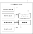
- FIG. 1 is a block diagram showing functions of the system design apparatus 1.
- the functions of the system design 1 are an analysis model reception unit (analysis model reception unit) 100, a minimum combination identification unit (minimum combination identification unit) 104, a requirement reception unit 105, and a minimum combination output unit (minimum combination identification unit) 106.
- the minimum combination output unit 104 includes a recovery time estimation unit (recovery time estimation unit) 107 and a cost estimation unit (cost estimation unit) 108.
- the analysis model reception unit 100 receives an analysis model that evaluates the failure recovery time based on the design of the failure recovery procedure.
- the analysis model shows the current system state, such as which part (component) of the system has failed and which part is operating normally, and the time and success required to execute each recovery operation.
- Parameters that represent characteristics such as the rate, changes in at least a part of the system due to the execution of each recovery operation during the disaster recovery procedure, and changes and recovery of the recovery operation that should be performed due to a change in the state of the system 3 is a model representing a control flow of a failure recovery procedure that expresses constraints on the execution order of operations.
- the analysis model is a state transition model in which state transition occurs based on a specific probability distribution.
- a state transition model for example, a Stochastic Reward Nets (hereinafter referred to as SRN) model is adopted.
- SRN Stochastic Reward Nets
- the state transition model may be appropriately selected, and in the present embodiment, the state transition model is not limited to the SRN model, and another state transition model may be employed.
- Requirement accepting unit 105 accepts and stores requirements for recovery time and cost previously input by a system designer or the like using an input device or the like.
- the minimum combination identification unit 104 estimates the recovery time for each combination of component failures using the recovery time estimation unit 107, estimates the cost using the cost estimation unit 108 from the estimated recovery time, and estimates the recovery time And the minimum combination of component failures that do not satisfy the requirements for the recovery time or cost received by the requirement receiving unit 105 from the cost.
- the recovery time estimation unit 107 described above estimates the recovery time by solving the analysis model received by the requirement reception unit 105 for each combination of component failures. For example, when the failure of the components X and Y is recovered based on the recovery procedure A, the recovery time is estimated such that the recovery is within 5 hours with a probability of 99%.
- the cost estimation unit 108 estimates the cost using a specific calculation formula based on the recovery time estimated by the recovery time estimation unit 107.
- the calculation formula includes, for example, an initial cost for constructing a disaster recovery system, a labor cost per hour for implementing a disaster recovery procedure, a downtime cost per unit time when a failure occurs. For example, when the failure of the components X and Y is recovered based on the recovery procedure A, the required cost is displayed as 10 million yen.
- the minimum combination output unit 106 presents the minimum combination specified by the minimum combination specifying unit 104. For example, “ ⁇ Component A, Component C, Component F ⁇ , ⁇ Component A, Component D, Component G ⁇ ” and the like may be presented on the display.
- the system design device 1 receives an analysis model representing a failure recovery procedure to be evaluated from a system designer (step S1000 shown in FIG. 2).
- the analysis model is an SRN model
- the system design device 1 may accept an analysis model described based on a notation method of an existing analysis tool such as Stochastic Petri Net Package (hereinafter referred to as SPNP).
- SPNP Stochastic Petri Net Package
- the system design device 1 estimates the recovery time for all combinations of component failures by solving the analysis model received in step S1000 (step S1030 shown in FIG. 2).
- the system design apparatus 1 solves the analysis model using an existing analysis tool such as SPNP.
- the initial position of one or more tokens representing the state of each part of the system on the SRN model (generally the initial distribution of tokens is called initial marking) is changed to change the combination of component failures.
- the recovery time is calculated as the time from the state representing “start of failure recovery procedure” to the state representing “complete recovery” on the model.
- the system design device 1 estimates the cost based on the recovery time estimated in step S1030 (step S1040 shown in FIG. 2).
- the system design device 1 proposed in the present embodiment calculates the total cost C total using the estimated recovery time value and the cost parameter value. For example, assuming that the recovery time is TTR and the cost-related parameters are personnel cost C recv for failure recovery per unit time, education cost C train for system operator performing recovery operation, equipment for executing failure recovery procedure Using the investment C initial , the time t violation exceeding the requirement for the recovery time, and the downtime cost D per unit time, the system design device 1 calculates the total cost C total by the following equation.
- the system design device 1 receives requirements for recovery time and cost from a system designer or the like (step S1050 shown in FIG. 2).
- the recovery time requirement can be set to 3 hours, and the total cost requirement can be set to 30 million yen. These values are system dependent.
- the system design apparatus 1 determines the minimum combination of component failures based on the recovery time and cost requirements obtained in step S1050, the recovery time obtained in step 1030, and the cost obtained in step 1040. Is identified (step S1060 shown in FIG. 2). Specifically, among the combinations of component faults that do not satisfy the requirements obtained in step S1050, the combination that minimizes the number of component faults is identified as the minimum combination.
- the system design device 1 outputs the minimum combination obtained in step S1060 to a display or the like (step S1070 shown in FIG. 2).
- the system design apparatus further has a configuration for automatically generating an analysis model from a failure recovery procedure with respect to the system design apparatus 1 according to the first embodiment.
- this configuration will be mainly described.
- FIG. 3 is a block diagram illustrating functions of the system design apparatus 1 according to the second embodiment.
- the function of the system design device 1 according to the second embodiment is as follows: A failure recovery procedure reception unit 101 and an analysis model generation unit 102 are included. Further, the function of the system design device 1 according to the second embodiment may not include the analysis model reception unit 100 among the functions of the system design device 1 according to the first embodiment.
- the failure recovery procedure receiving unit 101 receives a failure recovery procedure to be evaluated from the system designer.
- the system designer inputs, for example, a failure recovery procedure designed using an activity diagram of Systems Modeling Language (hereinafter referred to as SysML).
- SysML Systems Modeling Language
- the analysis model generation unit 102 generates an analysis model from the received failure recovery procedure. For example, the analysis model generation unit 102 converts the activity diagram into an SRN format analysis model based on a predefined conversion rule between the activity diagram and the SRN stored in the model module database 103 in advance. Other configurations are the same as those according to the first embodiment of the present invention shown in FIG.
- FIG. 4 is a flowchart showing an outline of the operation of the system design apparatus according to the second embodiment of the present invention.
- the system design apparatus receives a failure recovery procedure from the system designer (step S1010 shown in FIG. 4).
- the system designer describes a failure recovery procedure using an activity diagram.
- FIG. 5A, FIG. 5B, and FIG. 12 to FIG. 29 show examples of activity diagram notations
- FIG. 6 shows an example of an activity diagram showing a failure recovery procedure.
- FIG. 5A and FIG. 5B reference numbers for model components and drawing numbers representing model components corresponding to the reference numbers are described.
- nodes In this embodiment, five types of nodes are used to represent the characteristics of the failure recovery procedure. Hereinafter, each node will be described.
- ⁇ Action> Action represented by a rectangle represents one operation of the failure recovery procedure (for example, replacement, restart, data recovery, etc.).
- ⁇ DecisionNode> The DecisionNode represented by a diamond indicates that the output (yes or no) of a specific system component is present (for example, the component is operating normally or is out of order, a backup file exists or is present) (Refer to reference numbers 5A to F14 (1401 shown in FIG. 14) shown in FIG. 5A, d 1 , d 2, d 3 etc. shown in FIG. 6).
- the system designer determines which output of yes or no corresponds to the failure state of the component.
- the state of the component changes when a particular recovery operation is successfully performed. However, since there are unrecoverable failures, such a recovery operation does not always exist.
- InitialNode represented by a circle represents the starting point of the control flow of the failure recovery procedure (reference numbers 5A to F12 (1201 in FIG. 12) shown in FIG. 5 and 603 shown in FIG. 6).
- Activity Final represented by a circle with a black dot inside is the end point of the control flow in a state where the system is completely restored (for example, when a failed database server is restored with the latest data). (Reference numbers 5B-F22 (2201 in FIG. 22) shown in FIG. 5B and 604 shown in FIG. 6).
- Flow Final represented by a circle with a cross inside is a control flow in a state in which the system is partially failed (for example, when a failed database server is recovered in a state where data is damaged).
- Reference numbers 5B-F20 (2001 in FIG. 20) shown in FIG. 5B and 605 shown in FIG. 6).
- a recovery operation success rate r x and a recovery operation execution time trx are defined as parameters (1702 in FIG. 17, 606 in FIG. 6, etc.).
- a time t c ⁇ until the state check is completed is defined as a parameter (1402 in FIG. 14). The values of these parameters are specified in the note associated with the node, and are used as the transition rate (transition probability) of the synthesized SRN model.
- SysML allocation represents various relationships between SysML elements such as Action and DecisionNode.
- Action and DecisionNode.
- the following two stereotypes are defined for the allocation between the Action and the DecisionNode.
- ⁇ Control with condition> allocation of having this stereotype, from Action representing certain operations op x, to DecisionNode representing a certain conditional branch d theta is meant that the success of the execution of the op x is changed the output of the d theta (Reference number 5B-F24 (2401 in FIG. 24) shown in FIG. 5B, 609 shown in FIG. 6).
- the content of the change in the output of the DecisionNode due to the successful execution of a certain action is described as a condition in the note related to the allocation (2402 in FIG. 24, 610 shown in FIG. 6, etc.).
- the allocation from DecisionNode d ⁇ having this stereotype to DecisionNode d ⁇ means that the output of d ⁇ changes in accordance with the output of d ⁇ (reference numbers 5B to F26 shown in FIG. 5B (in FIG. 26). 2601)). Similarly, the content of the change due to d ⁇ is described as a condition in a note related to Allocation (2602 in FIG. 26). This allocation may be expressed as ⁇ control >> in the drawings of the present application.
- the failure recovery procedure operation may have a dependency in the execution order. For example, in order to recover from a failure, there is a case where another specific operation needs to be successful before the specific operation succeeds.
- ⁇ prior> is introduced as a stereotype for expressing such dependency relationships so that the system designer can clearly describe the constraints of these dependency relationships.
- Two operations op x, two Action representing the op y if there are two allocation with one DecisionNode d stereoptype that the ⁇ ⁇ control with condition>, allocation with stereotype that prior from op x to op y shows the meaning (see FIG. 5B No. 5B-F 28 (FIG. 28 that in order to change the output of the d theta is required successful execution of op x before the successful execution of op y 2801 )).
- the allocation may be expressed as ⁇ prior >> in the drawings of the present application.
- an analysis model is generated from the failure recovery procedure received in step S1010 (step S1020 shown in FIG. 4).
- the analysis model is expressed using an SRN model.
- the SRN model generated in step S1020 has three types of one or more system state models, one control flow model, and one or more restoration operation models. It consists of submodels.
- the control flow model represents the control flow of the input failure recovery procedure.
- Each restoration operation model represents one restoration operation.
- Each system state model represents a partial state (normally operating or malfunctioning) of the target system.
- the analysis model generation unit 102 follows the following three sub-steps based on a conversion rule between a part of an activity diagram (hereinafter referred to as an AD module) and a part of an SRN model (hereinafter referred to as an SRN model module). , SRN model is synthesized. 5A and 5B show an example of conversion rules between the elements of the failure recovery procedure and the elements of the analysis model.
- the analysis model generation unit 102 divides the received activity diagram into AD modules in sub-step 1.
- the analysis model generation unit 102 converts the AD module into an SRN model module.
- the analysis model generation unit 102 integrates the converted SRN model module into one SRN model.
- Sub-step 1 In sub-step 1, the analysis model generation unit 102, as shown in the third column of the table shown in FIGS. 5A and 5B, the input activity diagram, the AD module configured with nodes and output edges Divide into An edge input to each node of the AD module represents an output edge from the previous AD module (1403 in FIG. 14, 1703 in FIG. 17, etc.).
- the edge between the nodes in the AD module (f) “Control with Condition module I”, (g) “Control with Condition module II”, and (h) Prior Module in FIG. 5B represents the above-described allocation.
- the AD module in FIG. 5A (a) InitialNode module, (b) DecisionNode module, (c) Action module, and (d) FlowFinal module, (e) ActivityFinal module in FIG.
- the AD module includes an edge to the module.
- the AD module (f) “Control with Condition module I” in FIG. 5B, (g) “Control with Condition module II”, and (h) Prior Module include only allocation.
- the number of input edges for the AD module (a) InitialNode module in FIG. 5A is fixed to zero.
- the number of input edges for the AD module (b) DecisionNode module, (c) Action module, and the AD module (d) FlowFinal module, (e) ActivityFinal module in FIG. Dependent.
- each AD module shown in FIGS. 5A and 5B may be referred to using symbols (a) to (h).
- Sub-step 2 In sub-step 2, the analysis model generation unit 102 converts each AD module into a corresponding SRN model module as shown in columns 4 to 6 in the tables in FIGS. 5A and 5B.
- Sub-step 3 In sub-step 3, the analysis model generation unit 102 analyzes the SRN model module converted in sub-step 2 according to the connection relationship between the AD modules expressed in the conversion source activity diagram. Integrate into the SRN model. The output arc of each converted SRN model module is connected to the place of the SRN model module converted from the AD module, which is the connection destination in the conversion source activity diagram. Here, the place represents a state that the system can take in the SRN model.
- the output arc is a place P pre ⁇ (Fig. 5A reference number 5A-F15, 1501 in FIG. 15) or P execx (reference number 5A-F18 in FIG. 5A, 1801 in FIG. 18) or P unrecv ⁇ (reference number 5B-F21 in FIG. 5B, 2101 in FIG. 21) ) Or Precv (reference number 5B-F23 in FIG. 5B, 2301 in FIG. 23).
- the following naming convention is adopted for the names of the guard functions of the synthesized model. That is, when a transition has a guard function, the name of the transition has its guard function name as a subscript (the seventh column in the tables in FIGS. 5A and 5B). For example, for (b) DecisionNode module in FIG. 5A, the transition t gyes ⁇ has a guard function g yes ⁇ . The name of each guard function starts with “g” and its subscript is the name of the place that allows the transition with that guard function to fire when a token is present (see 10 in the tables in FIGS. 5A and 5B). Column).
- the transition represents a state transition in the system
- the guard function represents a condition in which the transition occurs.
- the place where the token exists represents the current state in the system.
- InitialNode module shown in FIG. 5A includes one InitialNode (reference numbers 5A to F12 (1201 in FIG. 12) in FIG. 5A) and one output edge (1202 in FIG. 12).
- the InitialNode module is converted into a place P init (reference number 5A-F13 (1301 in FIG. 13) in FIG. 5A and one output edge (1302 in FIG. 13) from the place of the control flow model.
- DecisionNode module shown in FIG. 5A includes one DecisionNode (1401 in FIG. 14) and two output edges (1404 in FIG. 14).
- the DecisionNode Module is converted into a control flow model and a system state model in the SRN model by the following (1) and (2).
- the DecisionNode Module is a place (P pre ⁇ and P dec ⁇ etc.) (1501 and 1502 in FIG. 15), transitions (t gyes ⁇ and t gno ⁇ in the control flow model shown in the reference numbers 5A to F15 (FIG. 15) in FIG. 5A. Etc.), and converted into an arc.
- the DecisionNode Module is converted into two places ( Pyes ⁇ and Pno ⁇ ) of the system state model indicated by reference numbers 5A to F16 (FIG. 16) in FIG. 5A (1601 and 1602 in FIG. 16).
- the transformed system state model has two places P yes ⁇ and P no ⁇ corresponding to the two outputs (1601 and 1602 in FIG. 16). There is one token in either Pyes ⁇ or Pno ⁇ .
- the analysis model generation unit 102 executes model analysis for a combination of a plurality of component faults, the initial token position (initial place) automatically changes. Token transitions between these places are determined by (f) or (g) as allocation shown in FIG. 5B.
- Action module shown in FIG. 5A has one action and one output edge (1701 and 1704 in FIG. 17).
- the Action module is converted into the control flow model and the recovery operation state model in the SRN model by the following (1) and (2).
- the Action module is converted into a place ( Pexecx , Preturnx, etc.), transition ( tgfinishx , tgbeforex, etc.) and arc of the control flow model (reference numbers 5A to F18 in FIG. 5 (FIG. 18)). ).
- the Action module is converted into one restoration operation model (reference numbers 5A to F19 (FIG. 19) in FIG. 5A).
- the transition rate T hexecx and the transition probability t successxx are the parameters input by the system designer, which are the success rate r x of the recovery operation and the value of the execution time t rx of the recovery operation. It is determined.
- r x and t rx are designated by note for conversion source AD module ( Figure 17).
- the control flow model and the restoration operation model in the converted SRN model module interact as follows.
- T hexecx can be ignited in the recovery operation model in (2) described above.
- token P Beforex moves P Branchx transition rate 1 / t 2 [1 / h ].
- t successx is fired in firing probability p 1, the token is moved to the P finishx via the P opx.
- an Action module representing a specific operation op x is associated with a specific DecisionNode d ⁇ by an allocation having ⁇ control >> as the stereotype (FIG. 24)
- the token of P opx is shown in FIG. 5B.
- FlowFinal module shown in FIG. 5B includes one FlowFinal.
- the Flow Final module is converted into one place of the control flow model shown in FIG. 5B (reference number 5B-F21 in FIG. 5B (2101 in FIG. 21)). This place is one of the end points of the control flow model. If there is a token in this place, it indicates that the disaster recovery procedure has been completed without complete recovery.
- ActivityFinal module shown in FIG. 5B includes one ActivityFinal.
- the ActivityFinal module is converted into one place of the control flow model shown in FIG. 5B (reference number 5B-F23 in FIG. 5B (2301 in FIG. 23)). This place is one of the end points of the control flow model. If there is a token in this place, it indicates that the disaster recovery procedure has been completed with a complete recovery.
- Control with condition module I illustrated in FIG. 5B includes one allocation from the action representing the operation op x having the above stereotype ⁇ control >> to the DecisionNode d ⁇ .
- Control with condition module I as the system state model shown in FIG. 5B, connecting two places of the transformed system state model from DecisionNode module including a conditional branch d ⁇ (P yes and P no), one It is converted into a transition, one input arc, and one output arc (reference numbers 5B-F25 in FIG. 5B, FIG. 25).
- the direction of transition between each place after conversion is defined from a fault state to a normally functioning state. The direction of transition is determined by the system designer.
- Control with condition module II shown in FIG. 5B has ⁇ control >> as the stereotype described above, and includes one allocation from DecisionNode d ⁇ to DecisionNode d ⁇ .
- Control with condition module II as the system state model shown in FIG. 5B, connecting two places of the transformed system state model from DecisionNode module including a conditional branch d theta, a single transition, one input arc, It is converted into one output arc (reference number 5B-F27 (FIG. 27) in FIG. 5B). The direction of the transition is the same as (f) “Control with condition module I”.
- the guard function g Yespusai or g no ⁇ only if the token is present in the P Yespusai or P no ⁇ , fire is t Gyespusai or t gno ⁇ , token moves from P Yesshita or P no ⁇ , the P Noshita or P Yesshita respectively.
- Priority module shown in FIG. 5B has ⁇ prior >> as the stereotype described above, and includes one allocation from the Action having the operation op x to the Action having the operation op y .
- Prior module as system state model shown in Figure 5B, one intermediate place between the two places of the transformed system state model from DicisionNode module including a conditional branch d theta, and are connected between these three places , Two transitions, two input arcs, and two output arcs (reference number 5B-F29 (FIG. 29) in FIG. 5B). The direction of the transition is the same as (f) “Control with condition module I”.
- the guard function g opx or g OPY token moves to P opx, then only if the token is moved to P OPY, token moves from P Yesshita or P no ⁇ , the P Noshita or P Yesshita respectively.
- FIG. 7 is a diagram showing an example of a control flow model that is a part of the analysis model generated from the failure recovery procedure shown in FIG.
- FIG. 8 is a diagram showing an example of a recovery procedure model that is a part of the analysis model generated from the failure recovery procedure shown in FIG.
- FIG. 9 is a diagram showing an example of a system state model that is a part of the analysis model generated from the failure recovery procedure shown in FIG.
- an analysis model based on an SRN model can be automatically generated from an activity diagram created by a system designer. For this reason, even system designers who do not have the mathematical modeling expertise required by model-based evaluation methods can evaluate, for example, the satisfaction of recovery requirements for failure recovery procedures designed using activity diagrams etc. .
- the system design apparatus according to the third embodiment of the present invention further has a configuration for pruning combinations of component faults to be analyzed with respect to the system design apparatuses according to the first and second embodiments described above. is doing.
- this configuration will be mainly described.
- step S1021 the system design device 1 prunes the combination of component failures to be analyzed (step S1021 shown in FIG. 11).
- step S1021 a specific pruning method in step S1021 will be described.
- step S1010 the combination of component failures leading to FlowFinal does not reach the complete recovery state of the system. For this reason, such a combination is excluded from the analysis target.
- the failure recovery procedure for the combination of different component failures analyze only the first time to eliminate duplication. For example, when a failure occurs in a physical server, an OS (Operating System) operating on the physical server must be restored after the physical server is restored regardless of whether the OS itself has failed. . As another example, if a component is operating normally but the backup file for that component is corrupted, an immediate recovery of the backup file is desirable but not essential for the recovery of the entire system.
- OS Operating System
- the system design device 1 receives a request for a recovery time and a cost (step S1022 shown in FIG. 11), similarly to step S1050 in the second embodiment.
- the system design device 1 takes out one combination of component faults from the combination that minimizes the number of faults of the included components (step S1023 shown in FIG. 11).
- the combination is selected from among combinations that have not been extracted yet and the number of included component failures is minimized (the combination that has been extracted once is not extracted again).
- the combination is excluded from analysis, and the process returns to step S1023 (FIG. 11).
- Yes in step S1024 shown in FIG. This is because the number of component failures included in the combination is greater than the minimum combination, and therefore cannot be the minimum combination.
- the process proceeds to step S1030 (in the case of No in step S1024 shown in FIG. 11).
- Steps 1030 to 1040 are performed on the extracted combinations as in the second embodiment.
- step S1060 Yes in step S1041 shown in FIG. 11
- steps S1060 to S1070 are performed as in the second embodiment.
- the process returns to step S1023 and the processing is continued.
- the recovery time and cost are used as evaluation indexes, but evaluation indexes related to other system requirements may be used.
- the recovery time is the time until the system is completely recovered from the failure.
- the failure recovery time may be the time until only an important part of the system is recovered.
- the plurality of the minimum combinations existing may be ranked when outputting the minimum combination. For example, each combination may be ranked according to the extent to which a failure recovery time or required cost requirement has been exceeded. Further, weighting may be performed for each component failure, and ranking may be performed based on the total weight.
- each function of the system design device 1 is realized by the CPU executing a program (software), but may be realized by a hardware device such as a dedicated circuit.
- the program is stored in the storage device, but may be stored in a computer-readable recording medium.
- the recording medium is a portable medium such as a flexible disk, an optical disk, a magneto-optical disk, and a semiconductor memory.
- the present invention is advantageous when applied to a system design apparatus that supports design of a system for failure recovery of an information processing system.
Landscapes
- Engineering & Computer Science (AREA)
- Theoretical Computer Science (AREA)
- General Engineering & Computer Science (AREA)
- Physics & Mathematics (AREA)
- General Physics & Mathematics (AREA)
- Software Systems (AREA)
- Quality & Reliability (AREA)
- Stored Programmes (AREA)
- Debugging And Monitoring (AREA)
Abstract
Description
まず、以下に説明する各実施形態における、障害復旧手順について説明する。以下の実施形態において、障害復旧手順は、障害の発生したコンポーネントを復旧するための手順である。障害復旧手順は、システムに含まれるコンポーネントの一部を復旧するサブ手順から構成される。各サブ手順は、リプレース、再起動、データ復旧、設定変更などのシステム管理操作を含む。各サブ手順は、復旧の対象となるコンポーネントに応じて予めドキュメントやマニュアルなどに記述される。
図1に示したように、第1の実施形態に係るシステム設計装置1の機能は情報処理装置によって実現される
(構成)
システム設計装置1は、例えば、サーバ装置、又は、パーソナル・コンピュータ等のコンピュータシステムによって構成される。
図1は、システム設計装置1の機能を表すブロック図である。システム設計1の機能は、解析モデル受付部(解析モデル受付手段)100と、最小組合せ特定部(最小組合せ特定手段)104と、要件受け付け部105と、最小組合せ出力部(最小組合せ特定手段)106と、を含んでいる。また、最小組合せ出力部104は、復旧時間推定部(復旧時間推定手段)107と、コスト推定部(コスト推定手段)108と、を含んでいる。
次に、上述したシステム設計装置1の作動について、図2を参照して説明する。
Ctotal = D×tviolation + Crecv×TTR + Ctrain + Cinital
なお、ステップS1030においてコンポーネント障害の全組合せについて復旧時間を求めた後、ステップS1040にてコンポーネント障害の全組合せについてコストを求めたが、コンポーネント障害の一つの組合せごとに復旧時間の推定・コストの推定を繰り返してもよい。
上述した本発明の第1の実施形態によれば、情報処理システムにおいて複数のコンポーネントに同時に発生する障害の解析において、当該障害の復旧時間または所要コストの要件を満たさないコンポーネント障害の最小の組み合わせを特定できる。本発明の第1の実施形態に係るシステム設計装置により、システム設計者は、現在の設計の限界を定量的に理解し、障害復旧に関わるシステム設計を効率的に改善できる。また、顧客の要求するシステム障害の復旧要件(復旧時間、コスト等)の充足可能性を容易に判断できる。
次に、本発明の第2の実施形態に係るシステム設計装置について、図3を参照して説明する。同図において図1と対応する部分には同一符号を付し、かかる部分の説明は省略する。
図3は、第2の実施形態に係るシステム設計装置1の機能を表すブロック図である。第2の実施形態に係るシステム設計装置1の機能は、第1の実施形態に係るシステム設計装置1の機能(最小組合せ特定部104,要件受付部105,最小組合せ出力部106)に加えて、障害復旧手順受付部101と、解析モデル生成部102を含む。また、第2の実施形態に係るシステム設計装置1の機能は、第1の実施形態に係るシステム設計装置1の機能のうち、解析モデル受付部100を含まなくてもよい。
次に、上述したシステム設計装置1の作動について、図4を参照して説明する。図4は、本発明の第2の実施形態に係るシステム設計装置の作動の概要を表すフローチャートである。
<DecisionNode>:菱形で表されるDecisionNodeは、その出力(yesまたはno)が特定のシステムコンポーネントの状態(例えば、コンポーネントが正常稼働中または故障中である、バックアップファイルが存在しているまたはしていない等)に応じて決定される条件分岐を表す(図5Aに示す参照番号5A-F14(図14に示す1401)、図6に示すd1、d2、d3等)。解析モデルの合成に必要な情報として、システム設計者はyesまたはnoのどちらの出力がコンポーネントの故障状態に相当するかを決定する。コンポーネントの状態は、特定の復旧操作の実行が成功すると、変化する。ただし、復旧不能な障害も存在するため、このような復旧操作は、常に存在するとは限らない。
以上、説明したように、本発明の第2の実施形態に係るシステム設計装置によれば、第1の実施形態に係るシステム設計装置1と同様の作用および効果を奏することができる。
次に、本発明の第3の実施形態に係るシステム設計装置について説明する。コンポーネント障害について、発生しうる全ての障害の組み合わせに対する復旧時間とコストを計算する場合、コンポーネント数が増加するにつれ、解析のための計算量は急速に増加する。よって、解析対象となるコンポーネント障害の組合せを枝刈りにすることにより、計算量を削減できるとよい。
図10に示したように、第3の実施形態に係るシステム設計装置1の機能は、第1又は第2の実施形態に係るシステム設計装置1の機能に加えて、最小組合せ特定部104に組合せ枝刈部109を含む。他の構成は上述した実施形態と同様であるので、本実施形態における説明は省略する。
次に、上述したシステム設計装置1の作動について、図11を参照して説明する。先ず、本実施形態におけるシステム設計装置1は、例えば、前記第2の実施形態と同様に、図4に示すステップS1010~ステップS1020を実施する。
以上、説明したように、本発明の第3の実施形態に係るシステム設計装置によれば、第1及び第2の実施形態に係るシステム設計装置1と同様の作用および効果を奏することができる。さらに、本発明の第3の実施形態に係るシステム設計装置1によれば、コンポーネントの組合せの枝刈りを行うことで、解析に要する計算量を削減できる。
100 解析モデル受付部
101 障害復旧手順受付部
102 解析モデル生成部
103 モデルモジュール
104 最小組合せ特定部
105 要件受付部
106 最小組合せ出力部
107 復旧時間推定部
108 コスト推定部
109 組合せ枝刈部
Claims (10)
- システムの障害復旧手順を表す解析モデルを受け付ける手段と、
受け付けた解析モデルから、復旧時間または所要コストの要件を満たさないコンポーネント障害の最小の組合せを特定する手段と、
特定したコンポーネント障害の最小の組合せを出力する手段と、を備え、
前記コンポーネント障害の最小の組合せを特定する手段は、
前記システムの復旧時間を推定する手段と、
前記システムの復旧に要するコストを推定する手段と、
を有するシステム設計装置。 - システムの障害復旧手順を受け付ける手段と、
受け付けた障害復旧手順から、モデルモジュールを組み合わせて解析モデルを生成する解析モデル生成部と、
生成した解析モデルから、復旧時間または所要コストの要件を満たさないコンポーネント障害の最小の組合せを特定する手段と、
特定したコンポーネント障害の最小の組合せを出力する手段と、を備え、
前記コンポーネント障害の最小の組合せを特定する手段は、
前記システムの復旧時間を推定する手段と、
前記システムの復旧に要するコストを推定する手段と、
を有するシステム設計装置。 - 請求項2に記載のシステム設計装置であって、
更に、解析の不要なコンポーネントの障害の組合せを枝刈りする組合せ枝刈部を備えるシステム設計装置。 - 前記解析モデルは、特定の確率分布に基づいて状態遷移が起こる状態遷移モデルである、請求項1乃至請求項3の何れかに記載のシステム設計装置。
- 前記障害復旧手順は、少なくとも、障害が発生したコンポーネントの状態に関する情報か、または障害が発生したコンポーネントを復旧するための障害復旧操作に関する情報か、または前記障害復旧操作が実行される条件に関する情報を含み、
前記解析モデル生成部は、
予め定められた前記障害復旧手順と前記解析モデルとの間の変換規則に基づいて、前記障害復旧手順に含まれる、前記システムの状態に関する情報と、障害復旧操作に関する情報と、障害復旧操作が実行される条件に関する情報とを、それぞれ前記解析モデルを構成する要素に変換し、
前記変換した前記解析モデルを構成する要素を統合して、前記解析モデルを生成する、
請求項2乃至請求項4の何れかに記載のシステム設計装置。 - 前記システムの障害復旧に関する、復旧時間と、復旧に要するコストの要件を受け付ける手段を更に有し、
前記コンポーネント障害の最小の組合せを特定する手段は、
前記受け付けた解析モデルに基づいて、前記システムの復旧時間と、前記システムの復旧に要するコストを推定し、
前記受け付けた、復旧時間と復旧に要するコストの要件と、前記推定した復旧時間と復旧に要するコストに基づいて、前記復旧時間または所要コストの要件を満たさないコンポーネント障害の最小の組合せを特定する、
請求項1乃至請求項5の何れかに記載のシステム設計装置。
- システムの障害復旧手順を表す解析モデルを受け付け、
受け付けた解析モデルから、復旧時間または所要コストの要件を満たさないコンポーネント障害の最小の組合せを特定し、
特定したコンポーネント障害の最小の組合せを出力する、システム設計方法であって、
前記コンポーネント障害の最小の組合せを特定する際に、
前記システムの復旧時間を推定し、
前記システムの復旧に要するコストを推定する、
システム設計方法。 - システムの障害復旧手順を表す解析モデルを受け付け、
前記システムの障害復旧に関する、復旧時間と、復旧に要するコストの要件を受け付け、
前記受け付けた解析モデルに基づいて、前記システムの復旧時間と、前記システムの復旧に要するコストを推定し、
前記受け付けた、復旧時間と復旧に要するコストの要件と、前記推定した復旧時間と復旧に要するコストに基づいて、前記復旧時間または所要コストの要件を満たさないコンポーネント障害の最小の組合せを特定し、
前記特定したコンポーネント障害の最小の組合せを出力する、システム設計方法。 - 情報処理装置に、
システムの障害復旧手順を表す解析モデルを受け付ける手段と、
受け付けた解析モデルから、復旧時間または所要コストの要件を満たさないコンポーネント障害の最小の組合せを特定する手段と、
特定したコンポーネント障害の最小の組合せを出力する手段と、
を実現させるためのシステム設計プログラムであって、
前記コンポーネント障害の最小の組合せを特定する手段は、
前記システムの復旧時間を推定する手段と、
前記システムの復旧に要するコストを推定する手段と、
を有するシステム設計プログラム。 - システムの障害復旧手順を設計するシステム設計ブログラムであって、
前記システムの障害復旧手順を表す解析モデルを受け付ける処理と、
前記システムの障害復旧に関する、復旧時間と復旧に要するコストの要件を受け付ける処理と、
前記受け付けた解析モデルに基づいて、前記システムの復旧時間と、前記システムの復旧に要するコストを推定する処理と、
前記受け付けた、復旧時間と復旧に要するコストの要件と、前記推定した復旧時間と復旧に要するコストに基づいて、前記復旧時間または所要コストの要件を満たさないコンポーネント障害の最小の組合せを特定する処理と、
前記特定したコンポーネント障害の最小の組合せを出力する処理と、
をコンピュータに実行させる、システム設計プログラム。
Priority Applications (2)
| Application Number | Priority Date | Filing Date | Title |
|---|---|---|---|
| JP2014541917A JPWO2014061199A1 (ja) | 2012-10-17 | 2013-09-17 | システム設計方法、システム設計装置及びシステム設計プログラム |
| US14/435,519 US9740575B2 (en) | 2012-10-17 | 2013-09-17 | System design method, system design apparatus, and storage medium storing system design program, for analyzing failure restoration procedure |
Applications Claiming Priority (2)
| Application Number | Priority Date | Filing Date | Title |
|---|---|---|---|
| JP2012230039 | 2012-10-17 | ||
| JP2012-230039 | 2012-10-17 |
Publications (1)
| Publication Number | Publication Date |
|---|---|
| WO2014061199A1 true WO2014061199A1 (ja) | 2014-04-24 |
Family
ID=50487780
Family Applications (1)
| Application Number | Title | Priority Date | Filing Date |
|---|---|---|---|
| PCT/JP2013/005471 WO2014061199A1 (ja) | 2012-10-17 | 2013-09-17 | システム設計方法、システム設計装置及びシステム設計プログラム |
Country Status (3)
| Country | Link |
|---|---|
| US (1) | US9740575B2 (ja) |
| JP (1) | JPWO2014061199A1 (ja) |
| WO (1) | WO2014061199A1 (ja) |
Cited By (1)
| Publication number | Priority date | Publication date | Assignee | Title |
|---|---|---|---|---|
| WO2015174068A1 (ja) * | 2014-05-16 | 2015-11-19 | 日本電気株式会社 | 情報処理装置、処理方法およびプログラムを記録した記録媒体 |
Families Citing this family (4)
| Publication number | Priority date | Publication date | Assignee | Title |
|---|---|---|---|---|
| US20130275113A1 (en) * | 2010-10-29 | 2013-10-17 | Nec Corporation | Availability model generation device |
| CN106021036B (zh) * | 2016-05-26 | 2019-10-18 | 工业和信息化部电子第五研究所 | 可重构系统故障分析方法和装置 |
| JP6904914B2 (ja) * | 2018-02-02 | 2021-07-21 | 株式会社日立製作所 | 決定表生成装置、及び決定表生成方法 |
| US11416326B2 (en) * | 2020-08-28 | 2022-08-16 | Sap Se | Systems and methods for failure diagnosis using fault tree |
Citations (4)
| Publication number | Priority date | Publication date | Assignee | Title |
|---|---|---|---|---|
| JP2001147951A (ja) * | 1999-11-22 | 2001-05-29 | Nippon Telegr & Teleph Corp <Ntt> | システム不信頼度算出方法、その装置及びそのプログラム記録媒体 |
| JP2005316696A (ja) * | 2004-04-28 | 2005-11-10 | Toshiba Corp | Itシステムの設計支援システムおよび設計支援方法 |
| JP2006503368A (ja) * | 2002-10-15 | 2006-01-26 | ザ プロクター アンド ギャンブル カンパニー | 多事象同時発生時の競合する原因事象の確率及び/又はシステムアベイラビリティを決定するプロセス |
| WO2012121005A1 (ja) * | 2011-03-04 | 2012-09-13 | 日本電気株式会社 | 可用性モデル生成支援装置、可用性モデル生成支援方法、およびプログラム |
Family Cites Families (12)
| Publication number | Priority date | Publication date | Assignee | Title |
|---|---|---|---|---|
| US7548873B2 (en) * | 2004-03-17 | 2009-06-16 | Schlumberger Technology Corporation | Method system and program storage device for automatically calculating and displaying time and cost data in a well planning system using a Monte Carlo simulation software |
| US20080082345A1 (en) * | 2006-09-29 | 2008-04-03 | Caterpillar Inc. | System and method for evaluating risks associated with delaying machine maintenance |
| US9088615B1 (en) * | 2008-07-31 | 2015-07-21 | Pulse Secure, Llc | Determining a reduced set of remediation actions for endpoint integrity |
| US10027711B2 (en) * | 2009-11-20 | 2018-07-17 | Alert Enterprise, Inc. | Situational intelligence |
| US8494826B2 (en) * | 2010-01-13 | 2013-07-23 | The United States Postal Service | Systems and methods for analyzing equipment failures and maintenance schedules |
| US8428921B2 (en) * | 2010-08-12 | 2013-04-23 | International Business Machines Corporation | Dynamically adjusting simulation fidelity based on checkpointed fidelity state |
| US20130275113A1 (en) | 2010-10-29 | 2013-10-17 | Nec Corporation | Availability model generation device |
| JP5601468B2 (ja) | 2010-11-26 | 2014-10-08 | 日本電気株式会社 | 故障の木の最小カットセットを効率的に評価する方法とシステム |
| US20120191503A1 (en) * | 2011-01-24 | 2012-07-26 | Bank Of America Corporation | Incident cost model |
| US20140129272A1 (en) * | 2012-11-05 | 2014-05-08 | Pacific Gas And Electric Company | System and method for managing service restoration in a utility network |
| US20140257909A1 (en) * | 2013-03-11 | 2014-09-11 | International Business Machines Corporation | Estimating project cost |
| US10749825B2 (en) * | 2015-04-29 | 2020-08-18 | International Business Machines Corporation | Email cost analytics |
-
2013
- 2013-09-17 JP JP2014541917A patent/JPWO2014061199A1/ja active Pending
- 2013-09-17 US US14/435,519 patent/US9740575B2/en not_active Expired - Fee Related
- 2013-09-17 WO PCT/JP2013/005471 patent/WO2014061199A1/ja active Application Filing
Patent Citations (4)
| Publication number | Priority date | Publication date | Assignee | Title |
|---|---|---|---|---|
| JP2001147951A (ja) * | 1999-11-22 | 2001-05-29 | Nippon Telegr & Teleph Corp <Ntt> | システム不信頼度算出方法、その装置及びそのプログラム記録媒体 |
| JP2006503368A (ja) * | 2002-10-15 | 2006-01-26 | ザ プロクター アンド ギャンブル カンパニー | 多事象同時発生時の競合する原因事象の確率及び/又はシステムアベイラビリティを決定するプロセス |
| JP2005316696A (ja) * | 2004-04-28 | 2005-11-10 | Toshiba Corp | Itシステムの設計支援システムおよび設計支援方法 |
| WO2012121005A1 (ja) * | 2011-03-04 | 2012-09-13 | 日本電気株式会社 | 可用性モデル生成支援装置、可用性モデル生成支援方法、およびプログラム |
Non-Patent Citations (1)
| Title |
|---|
| KUMIKO TADANO ET AL.: "Activity-zu de Kijutsu sareta System Un'yo Sosa kara no Kayosei Model Gosei Hoshiki", DAI 73 KAI (HEISEI 23 NEN) ZENKOKU TAIKAI KOEN RONBUNSHU (1), 2 March 2011 (2011-03-02), pages 1-263 - 1-264 * |
Cited By (3)
| Publication number | Priority date | Publication date | Assignee | Title |
|---|---|---|---|---|
| WO2015174068A1 (ja) * | 2014-05-16 | 2015-11-19 | 日本電気株式会社 | 情報処理装置、処理方法およびプログラムを記録した記録媒体 |
| JPWO2015174068A1 (ja) * | 2014-05-16 | 2017-04-20 | 日本電気株式会社 | 情報処理装置、処理方法およびプログラム |
| US10180882B2 (en) | 2014-05-16 | 2019-01-15 | Nec Corporation | Information-processing device, processing method, and recording medium in which program is recorded |
Also Published As
| Publication number | Publication date |
|---|---|
| US9740575B2 (en) | 2017-08-22 |
| US20150301908A1 (en) | 2015-10-22 |
| JPWO2014061199A1 (ja) | 2016-09-05 |
Similar Documents
| Publication | Publication Date | Title |
|---|---|---|
| JP6607565B2 (ja) | セーフティクリティカルソフトウェアのための統合された自動テストケース生成 | |
| WO2014061199A1 (ja) | システム設計方法、システム設計装置及びシステム設計プログラム | |
| WO2011148891A1 (ja) | システムモデルからの静的なフォルトツリー解析のシステムと方法 | |
| AU2018260855A1 (en) | Hybrid cloud migration delay risk prediction engine | |
| JP6249016B2 (ja) | 障害復旧手順生成装置、障害復旧手順生成方法および障害復旧手順生成プログラム | |
| JP6268029B2 (ja) | テストケース生成装置及びテストケース生成方法 | |
| JPWO2012073686A1 (ja) | ディペンダビリティ維持システム、変化対応サイクル実行装置、障害対応サイクル実行装置、ディペンダビリティ維持システムの制御方法、制御プログラムおよびそれを記録したコンピュータ読み取り可能な記録媒体 | |
| JP2016115175A (ja) | ソフトウェアテスト装置およびソフトウェアテストプログラム | |
| WO2014181495A1 (ja) | 仮想マシン配置決定装置、仮想マシン配置決定方法および仮想マシン配置決定プログラム | |
| WO2009144826A1 (ja) | 検査用ファイル生成プログラム、検査用ファイル生成装置および検査用ファイル生成方法 | |
| WO2013168495A1 (ja) | 階層型確率モデル生成システム、階層型確率モデル生成方法、およびプログラム | |
| CN106339553A (zh) | 一种空间飞行器的重构飞行控制方法及系统 | |
| WO2012131868A1 (ja) | 計算機システムの管理方法及び管理装置 | |
| Gallina et al. | Deriving verification-related means of compliance for a model-based testing process | |
| US11586976B2 (en) | Method and apparatus for creating tests for execution in a storage environment | |
| US8650142B2 (en) | Method and device for performing a maintenance function | |
| JP2011065576A (ja) | テストケース生成装置およびその方法 | |
| US20120291019A1 (en) | Program verification apparatus based on model verifying and storage medium | |
| WO2012121005A1 (ja) | 可用性モデル生成支援装置、可用性モデル生成支援方法、およびプログラム | |
| WO2013031129A1 (ja) | 情報処理装置、情報処理方法、及びプログラム | |
| WO2012049816A1 (ja) | モデル検査装置、方法及びプログラム | |
| WO2015072078A1 (ja) | サービス再開手順生成装置、サービス再開手順生成方法およびサービス再開手順生成プログラム | |
| Carson et al. | 2.5. 1 Functional Architecture as the Core of Model‐Based Systems Engineering | |
| US10180882B2 (en) | Information-processing device, processing method, and recording medium in which program is recorded | |
| JP5875607B2 (ja) | 性能モデル検査装置、方法およびプログラム |
Legal Events
| Date | Code | Title | Description |
|---|---|---|---|
| 121 | Ep: the epo has been informed by wipo that ep was designated in this application |
Ref document number: 13846309 Country of ref document: EP Kind code of ref document: A1 |
|
| ENP | Entry into the national phase |
Ref document number: 2014541917 Country of ref document: JP Kind code of ref document: A |
|
| WWE | Wipo information: entry into national phase |
Ref document number: 14435519 Country of ref document: US |
|
| NENP | Non-entry into the national phase |
Ref country code: DE |
|
| 122 | Ep: pct application non-entry in european phase |
Ref document number: 13846309 Country of ref document: EP Kind code of ref document: A1 |