WO2014054780A1 - Container with shrink-fit label, shrink-fit label, and manufacturing method for container with shrink-fit label - Google Patents
Container with shrink-fit label, shrink-fit label, and manufacturing method for container with shrink-fit label Download PDFInfo
- Publication number
- WO2014054780A1 WO2014054780A1 PCT/JP2013/077080 JP2013077080W WO2014054780A1 WO 2014054780 A1 WO2014054780 A1 WO 2014054780A1 JP 2013077080 W JP2013077080 W JP 2013077080W WO 2014054780 A1 WO2014054780 A1 WO 2014054780A1
- Authority
- WO
- WIPO (PCT)
- Prior art keywords
- container
- shrink label
- inspection mark
- shrink
- lateral
- Prior art date
Links
- 238000004519 manufacturing process Methods 0.000 title claims description 6
- 238000002372 labelling Methods 0.000 title 1
- 238000007689 inspection Methods 0.000 claims description 237
- 238000006073 displacement reaction Methods 0.000 claims description 34
- 238000000034 method Methods 0.000 claims description 31
- 238000001514 detection method Methods 0.000 abstract description 3
- 238000005259 measurement Methods 0.000 description 16
- 238000013461 design Methods 0.000 description 12
- 238000000926 separation method Methods 0.000 description 11
- 238000003384 imaging method Methods 0.000 description 9
- 230000002093 peripheral effect Effects 0.000 description 8
- 230000008602 contraction Effects 0.000 description 6
- 238000007639 printing Methods 0.000 description 6
- 239000000853 adhesive Substances 0.000 description 5
- 230000001070 adhesive effect Effects 0.000 description 5
- -1 polyethylene Polymers 0.000 description 4
- 229920006300 shrink film Polymers 0.000 description 4
- 239000000758 substrate Substances 0.000 description 4
- 239000004793 Polystyrene Substances 0.000 description 3
- 229920000728 polyester Polymers 0.000 description 3
- 229920000139 polyethylene terephthalate Polymers 0.000 description 3
- 239000005020 polyethylene terephthalate Substances 0.000 description 3
- 229920005989 resin Polymers 0.000 description 3
- 239000011347 resin Substances 0.000 description 3
- 239000004698 Polyethylene Substances 0.000 description 2
- 239000004743 Polypropylene Substances 0.000 description 2
- 239000011248 coating agent Substances 0.000 description 2
- 238000000576 coating method Methods 0.000 description 2
- 238000005520 cutting process Methods 0.000 description 2
- 238000007646 gravure printing Methods 0.000 description 2
- 229920001707 polybutylene terephthalate Polymers 0.000 description 2
- 229920000573 polyethylene Polymers 0.000 description 2
- 239000004626 polylactic acid Substances 0.000 description 2
- 229920001155 polypropylene Polymers 0.000 description 2
- 229920002223 polystyrene Polymers 0.000 description 2
- 238000012545 processing Methods 0.000 description 2
- 230000000630 rising effect Effects 0.000 description 2
- 238000012360 testing method Methods 0.000 description 2
- 239000004952 Polyamide Substances 0.000 description 1
- 230000015572 biosynthetic process Effects 0.000 description 1
- 230000000903 blocking effect Effects 0.000 description 1
- 238000000071 blow moulding Methods 0.000 description 1
- 238000012937 correction Methods 0.000 description 1
- 230000002950 deficient Effects 0.000 description 1
- 230000003111 delayed effect Effects 0.000 description 1
- 238000010438 heat treatment Methods 0.000 description 1
- 238000005286 illumination Methods 0.000 description 1
- 238000001746 injection moulding Methods 0.000 description 1
- 230000001678 irradiating effect Effects 0.000 description 1
- 239000000463 material Substances 0.000 description 1
- 238000000691 measurement method Methods 0.000 description 1
- 239000000203 mixture Substances 0.000 description 1
- 238000000465 moulding Methods 0.000 description 1
- 229920000747 poly(lactic acid) Polymers 0.000 description 1
- 229920002647 polyamide Polymers 0.000 description 1
- 229920000098 polyolefin Polymers 0.000 description 1
- 239000004800 polyvinyl chloride Substances 0.000 description 1
- 229920000915 polyvinyl chloride Polymers 0.000 description 1
- 238000003892 spreading Methods 0.000 description 1
- 229920003002 synthetic resin Polymers 0.000 description 1
- 239000000057 synthetic resin Substances 0.000 description 1
- 230000000007 visual effect Effects 0.000 description 1
- XLYOFNOQVPJJNP-UHFFFAOYSA-N water Substances O XLYOFNOQVPJJNP-UHFFFAOYSA-N 0.000 description 1
Images


Classifications
-
- B—PERFORMING OPERATIONS; TRANSPORTING
- B65—CONVEYING; PACKING; STORING; HANDLING THIN OR FILAMENTARY MATERIAL
- B65D—CONTAINERS FOR STORAGE OR TRANSPORT OF ARTICLES OR MATERIALS, e.g. BAGS, BARRELS, BOTTLES, BOXES, CANS, CARTONS, CRATES, DRUMS, JARS, TANKS, HOPPERS, FORWARDING CONTAINERS; ACCESSORIES, CLOSURES, OR FITTINGS THEREFOR; PACKAGING ELEMENTS; PACKAGES
- B65D25/00—Details of other kinds or types of rigid or semi-rigid containers
- B65D25/20—External fittings
- B65D25/205—Means for the attachment of labels, cards, coupons or the like
-
- B—PERFORMING OPERATIONS; TRANSPORTING
- B65—CONVEYING; PACKING; STORING; HANDLING THIN OR FILAMENTARY MATERIAL
- B65D—CONTAINERS FOR STORAGE OR TRANSPORT OF ARTICLES OR MATERIALS, e.g. BAGS, BARRELS, BOTTLES, BOXES, CANS, CARTONS, CRATES, DRUMS, JARS, TANKS, HOPPERS, FORWARDING CONTAINERS; ACCESSORIES, CLOSURES, OR FITTINGS THEREFOR; PACKAGING ELEMENTS; PACKAGES
- B65D25/00—Details of other kinds or types of rigid or semi-rigid containers
- B65D25/34—Coverings or external coatings
- B65D25/36—Coverings or external coatings formed by applying sheet material
-
- B—PERFORMING OPERATIONS; TRANSPORTING
- B29—WORKING OF PLASTICS; WORKING OF SUBSTANCES IN A PLASTIC STATE IN GENERAL
- B29C—SHAPING OR JOINING OF PLASTICS; SHAPING OF MATERIAL IN A PLASTIC STATE, NOT OTHERWISE PROVIDED FOR; AFTER-TREATMENT OF THE SHAPED PRODUCTS, e.g. REPAIRING
- B29C65/00—Joining or sealing of preformed parts, e.g. welding of plastics materials; Apparatus therefor
- B29C65/66—Joining or sealing of preformed parts, e.g. welding of plastics materials; Apparatus therefor by liberation of internal stresses, e.g. shrinking of one of the parts to be joined
- B29C65/665—Joining or sealing of preformed parts, e.g. welding of plastics materials; Apparatus therefor by liberation of internal stresses, e.g. shrinking of one of the parts to be joined using shrinking during cooling
-
- B—PERFORMING OPERATIONS; TRANSPORTING
- B65—CONVEYING; PACKING; STORING; HANDLING THIN OR FILAMENTARY MATERIAL
- B65B—MACHINES, APPARATUS OR DEVICES FOR, OR METHODS OF, PACKAGING ARTICLES OR MATERIALS; UNPACKING
- B65B57/00—Automatic control, checking, warning, or safety devices
-
- B—PERFORMING OPERATIONS; TRANSPORTING
- B65—CONVEYING; PACKING; STORING; HANDLING THIN OR FILAMENTARY MATERIAL
- B65C—LABELLING OR TAGGING MACHINES, APPARATUS, OR PROCESSES
- B65C3/00—Labelling other than flat surfaces
- B65C3/06—Affixing labels to short rigid containers
- B65C3/065—Affixing labels to short rigid containers by placing tubular labels around the container
-
- B—PERFORMING OPERATIONS; TRANSPORTING
- B65—CONVEYING; PACKING; STORING; HANDLING THIN OR FILAMENTARY MATERIAL
- B65D—CONTAINERS FOR STORAGE OR TRANSPORT OF ARTICLES OR MATERIALS, e.g. BAGS, BARRELS, BOTTLES, BOXES, CANS, CARTONS, CRATES, DRUMS, JARS, TANKS, HOPPERS, FORWARDING CONTAINERS; ACCESSORIES, CLOSURES, OR FITTINGS THEREFOR; PACKAGING ELEMENTS; PACKAGES
- B65D25/00—Details of other kinds or types of rigid or semi-rigid containers
- B65D25/20—External fittings
-
- B—PERFORMING OPERATIONS; TRANSPORTING
- B65—CONVEYING; PACKING; STORING; HANDLING THIN OR FILAMENTARY MATERIAL
- B65D—CONTAINERS FOR STORAGE OR TRANSPORT OF ARTICLES OR MATERIALS, e.g. BAGS, BARRELS, BOTTLES, BOXES, CANS, CARTONS, CRATES, DRUMS, JARS, TANKS, HOPPERS, FORWARDING CONTAINERS; ACCESSORIES, CLOSURES, OR FITTINGS THEREFOR; PACKAGING ELEMENTS; PACKAGES
- B65D25/00—Details of other kinds or types of rigid or semi-rigid containers
- B65D25/34—Coverings or external coatings
-
- G—PHYSICS
- G09—EDUCATION; CRYPTOGRAPHY; DISPLAY; ADVERTISING; SEALS
- G09F—DISPLAYING; ADVERTISING; SIGNS; LABELS OR NAME-PLATES; SEALS
- G09F3/00—Labels, tag tickets, or similar identification or indication means; Seals; Postage or like stamps
- G09F3/04—Labels, tag tickets, or similar identification or indication means; Seals; Postage or like stamps to be fastened or secured by the material of the label itself, e.g. by thermo-adhesion
-
- B—PERFORMING OPERATIONS; TRANSPORTING
- B29—WORKING OF PLASTICS; WORKING OF SUBSTANCES IN A PLASTIC STATE IN GENERAL
- B29C—SHAPING OR JOINING OF PLASTICS; SHAPING OF MATERIAL IN A PLASTIC STATE, NOT OTHERWISE PROVIDED FOR; AFTER-TREATMENT OF THE SHAPED PRODUCTS, e.g. REPAIRING
- B29C63/00—Lining or sheathing, i.e. applying preformed layers or sheathings of plastics; Apparatus therefor
- B29C63/38—Lining or sheathing, i.e. applying preformed layers or sheathings of plastics; Apparatus therefor by liberation of internal stresses
- B29C63/42—Lining or sheathing, i.e. applying preformed layers or sheathings of plastics; Apparatus therefor by liberation of internal stresses using tubular layers or sheathings
-
- B—PERFORMING OPERATIONS; TRANSPORTING
- B29—WORKING OF PLASTICS; WORKING OF SUBSTANCES IN A PLASTIC STATE IN GENERAL
- B29K—INDEXING SCHEME ASSOCIATED WITH SUBCLASSES B29B, B29C OR B29D, RELATING TO MOULDING MATERIALS OR TO MATERIALS FOR MOULDS, REINFORCEMENTS, FILLERS OR PREFORMED PARTS, e.g. INSERTS
- B29K2995/00—Properties of moulding materials, reinforcements, fillers, preformed parts or moulds
- B29K2995/0037—Other properties
- B29K2995/0049—Heat shrinkable
-
- B—PERFORMING OPERATIONS; TRANSPORTING
- B29—WORKING OF PLASTICS; WORKING OF SUBSTANCES IN A PLASTIC STATE IN GENERAL
- B29L—INDEXING SCHEME ASSOCIATED WITH SUBCLASS B29C, RELATING TO PARTICULAR ARTICLES
- B29L2031/00—Other particular articles
- B29L2031/712—Containers; Packaging elements or accessories, Packages
-
- B—PERFORMING OPERATIONS; TRANSPORTING
- B32—LAYERED PRODUCTS
- B32B—LAYERED PRODUCTS, i.e. PRODUCTS BUILT-UP OF STRATA OF FLAT OR NON-FLAT, e.g. CELLULAR OR HONEYCOMB, FORM
- B32B2307/00—Properties of the layers or laminate
- B32B2307/40—Properties of the layers or laminate having particular optical properties
- B32B2307/412—Transparent
-
- B—PERFORMING OPERATIONS; TRANSPORTING
- B32—LAYERED PRODUCTS
- B32B—LAYERED PRODUCTS, i.e. PRODUCTS BUILT-UP OF STRATA OF FLAT OR NON-FLAT, e.g. CELLULAR OR HONEYCOMB, FORM
- B32B27/00—Layered products comprising a layer of synthetic resin
- B32B27/32—Layered products comprising a layer of synthetic resin comprising polyolefins
-
- B—PERFORMING OPERATIONS; TRANSPORTING
- B65—CONVEYING; PACKING; STORING; HANDLING THIN OR FILAMENTARY MATERIAL
- B65C—LABELLING OR TAGGING MACHINES, APPARATUS, OR PROCESSES
- B65C9/00—Details of labelling machines or apparatus
- B65C9/40—Controls; Safety devices
- B65C2009/402—Controls; Safety devices for detecting properties or defects of labels
- B65C2009/407—Controls; Safety devices for detecting properties or defects of labels after labelling
-
- B—PERFORMING OPERATIONS; TRANSPORTING
- B65—CONVEYING; PACKING; STORING; HANDLING THIN OR FILAMENTARY MATERIAL
- B65D—CONTAINERS FOR STORAGE OR TRANSPORT OF ARTICLES OR MATERIALS, e.g. BAGS, BARRELS, BOTTLES, BOXES, CANS, CARTONS, CRATES, DRUMS, JARS, TANKS, HOPPERS, FORWARDING CONTAINERS; ACCESSORIES, CLOSURES, OR FITTINGS THEREFOR; PACKAGING ELEMENTS; PACKAGES
- B65D2203/00—Decoration means, markings, information elements, contents indicators
- B65D2203/02—Labels
-
- Y—GENERAL TAGGING OF NEW TECHNOLOGICAL DEVELOPMENTS; GENERAL TAGGING OF CROSS-SECTIONAL TECHNOLOGIES SPANNING OVER SEVERAL SECTIONS OF THE IPC; TECHNICAL SUBJECTS COVERED BY FORMER USPC CROSS-REFERENCE ART COLLECTIONS [XRACs] AND DIGESTS
- Y10—TECHNICAL SUBJECTS COVERED BY FORMER USPC
- Y10T—TECHNICAL SUBJECTS COVERED BY FORMER US CLASSIFICATION
- Y10T428/00—Stock material or miscellaneous articles
- Y10T428/24—Structurally defined web or sheet [e.g., overall dimension, etc.]
- Y10T428/24802—Discontinuous or differential coating, impregnation or bond [e.g., artwork, printing, retouched photograph, etc.]
Definitions
- the present invention relates to a container with a shrink label to which a shrink label is attached, a shrink label used for the container with the shrink label, and a method for manufacturing the container with the shrink label.
- the present applicant can inspect the vertical position shift of the shrink label with respect to the container at the bottom part of the container in the container with the shrink label so as to cover not only the side part but also the bottom part of the container.
- An inspection method was considered (see Patent Document 3 below). However, although this inspection method is suitable for inspecting the positional displacement of the shrink label in the vertical direction, it is not suitable for inspecting the lateral displacement of the shrink label, that is, the circumferential direction.
- Such a lateral displacement of the shrink label with respect to the container occurs, for example, when the shrink label is placed on the container with the shrink label relatively displaced laterally with respect to the container.
- the shrink label is displaced in the lateral direction substantially uniformly over the entire circumference.
- the shrink label when the shrink label is thermally shrunk, even if the shrink label is not uniformly heat shrunk over the entire circumference, a lateral displacement of the shrink label with respect to the container occurs.
- the degree of shrinkage when the degree of shrinkage is large at the front position in the entire circumference of the shrink label, but the degree of shrinkage is small at the back position, the design of the shrink label is biased toward the front side.
- the degree of contraction is large at the right position in the entire circumference of the shrink label, but the degree of contraction is small at the left position, the design of the shrink label is biased to the right.
- Such a lateral displacement of the shrink label is not often a problem in a circular container with a circular cross-sectional view.
- the horizontal position of the shrink label with respect to the container is It is important and it is necessary to prevent the displacement.
- the lateral position of the shrink label with respect to the container is important. This is not limited to a rectangular container, but can be applied to all containers in which the lateral displacement of the shrink label can be a problem, and a new inspection method corresponding to such a problem is required.
- the present invention has been made in view of the above-described conventional problems, and enables a lateral displacement of the shrink label to be inspected in a container in which the shrink label is mounted not only on the side surface but also on the bottom surface. This is the issue.
- the container with a shrink label according to the present invention is a container with a shrink label to which a shrink label is attached from the side surface portion to the bottom surface portion of the container,
- the bottom surface covering portion of the shrink label covering the bottom surface portion is provided with a lateral direction inspection mark for inspecting the lateral displacement of the shrink label with respect to the container.
- the horizontal inspection mark is imaged by an imaging unit, the image data is image-processed by an image processing unit, the position of the horizontal inspection mark is specified, and the position of the horizontal inspection mark is determined in advance. It is discriminated by the discriminating means whether or not it is within the specified allowable range. That is, when the horizontal inspection mark is located within a predetermined range with respect to the reference position, the lateral displacement of the shrink label with respect to the container is within the allowable range. If the horizontal inspection mark is located outside the specified range with respect to the reference position, the shrinkage of the shrink label in the horizontal direction with respect to the container exceeds the allowable range.
- a container with a label can be determined as an NG product (defective product).
- the horizontal inspection mark has a side edge extending in a direction substantially orthogonal to the lower end edge of the shrink label. According to this configuration, the lateral position can be accurately identified by recognizing the side edge of the image.
- the horizontal inspection mark is a line extending in a direction substantially orthogonal to the lower end edge of the shrink label.
- either or both of the both side edges of the horizontal inspection mark can be used, and since the horizontal inspection mark is linear, the center position between both side edges is set in the horizontal direction. It can also be the position of the inspection mark.
- the side surface portion of the container is rectangular in a cross-sectional view
- the bottom surface covering portion is composed of four side portions corresponding to the four wall surfaces of the side surface portion, and at least one side portion of the four side portions is formed. It is preferable that a lateral inspection mark is provided in the lateral central region. Since the bottom edge of the shrink label greatly changes the direction of the corner portion between the adjacent side portions in the bottom surface covering portion, if a lateral inspection mark is provided in the vicinity of the corner portion, measurement tends to vary. Therefore, it is preferable to provide a lateral inspection mark in the lateral central region away from the corner portion, and measurement variations can be suppressed.
- a lateral inspection mark is provided on each of a pair of opposing sides of the four sides.
- the opposing direction of the pair of opposing wall surfaces among the four wall surfaces of the container is the X axis
- the opposing direction of the remaining pair of wall surfaces is the Y axis.
- the X-axis direction from any one of the pair of wall surfaces facing in the X-axis direction to the lateral inspection mark It is also possible to determine OK / NG based on whether or not the distance is within a predetermined range.
- the lateral displacement of the shrink label with respect to the container appears to be enlarged. Therefore, it becomes possible to measure with higher accuracy. Furthermore, since it can be inspected in which direction the other lateral inspection mark is displaced with respect to one lateral inspection mark, the directionality of the positional deviation of the shrink label can also be inspected.
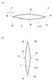
- the side surface of the container is oval in cross-sectional view, at least one of the total of four locations on the bottom surface covering portion, two on the major axis and two on the minor axis.
- a direction inspection mark is preferably provided.
- the bottom surface of the container is viewed from the front, the bottom surface of the container is elliptical, but the long axis is parallel to, for example, the X axis, and the short axis is parallel to the Y axis. The displacement of the inspection mark can be easily measured.
- a vertical inspection mark for inspecting the vertical displacement of the shrink label with respect to the container is formed on the bottom surface covering portion in a linear shape extending along the lower end edge of the shrink label, and at least one of the horizontal inspection marks. It is preferable that the part is located inside the vertical inspection mark.
- the inner side of the vertical inspection mark is the side close to the lower end edge of the shrink label.
- the vertical inspection mark is formed in a line shape along the lower edge of the shrink label as described above, it is preferable that at least a part of the horizontal inspection mark is located inside the vertical inspection mark. The positional deviation can be detected with higher accuracy.
- the shrink label according to the present invention is a shrink label that is mounted from the side surface portion to the bottom surface portion of the container, and inspects the lateral displacement of the shrink label with respect to the container in the portion covering the bottom surface portion of the container.
- the horizontal direction inspection mark is provided.
- lateral inspection marks are respectively provided at two positions that bisect the entire circumference of the shrink label. That is, by providing at least two lateral inspection marks, it is possible to perform inspection with higher accuracy than when only one lateral inspection mark is provided. If the horizontal inspection mark is provided at a position that bisects the entire circumference of the shrink label, the distance between the two horizontal inspection marks is measured, thereby further increasing the accuracy. Inspection is possible.
- the separation distance in the X-axis direction or Y By measuring the separation distance in the axial direction, it is possible to accurately inspect the lateral displacement of the shrink label with respect to the container.
- the method for manufacturing a container with a shrink label includes a step of covering the side surface portion of the container with the shrink label provided with the horizontal direction inspection mark, and a lateral inspection on the portion of the shrink label covering the bottom surface portion of the container.
- the shrink label is thermally shrunk so that the mark is positioned and attached to the container, and the position of the horizontal inspection mark of the shrink label attached to the container is measured to determine the lateral position of the shrink label relative to the container.
- a step of inspecting deviation is
- the container with the shrink label according to the present invention is provided with the horizontal direction inspection mark on the bottom surface covering portion of the shrink label covering the bottom surface portion of the container, so the shrink label is attached to the bottom surface portion. Even in a container such as a rectangular container, the lateral displacement of the shrink label can be inspected.
- the shrink label according to the present invention is provided with a horizontal inspection mark on the portion of the shrink label that covers the bottom surface of the container, the lateral displacement is inspected when the shrink label is attached to a container such as a rectangular container. can do.
- the manufacturing method of the container with a shrink label according to the present invention includes a step of inspecting a lateral displacement of the shrink label with respect to the container by measuring a position of the horizontal inspection mark of the shrink label attached to the container. Since it is provided, the lateral displacement of the shrink label can be inspected even in a container such as a rectangular container having the shrink label attached to the bottom surface.
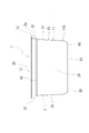
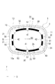
- the perspective view which shows the container with a shrink label in one Embodiment of this invention The front view which shows the container currently used for the container with the said shrink label. It is a bottom view which shows the container with the shrink label, Comprising: The thing with the shrink label mounted
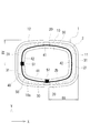
- the bottom view which shows the inspection method of the position shift of the shrink label of the shrink label in the container with the shrink label.
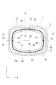
- the bottom view which shows the inspection method of the position shift of the horizontal direction of a shrink label in the container with a shrink label in other embodiment of this invention.
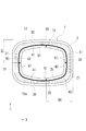
- the bottom view which shows the inspection method of the position shift of the shrink label of the shrink label in the container with the shrink label.
- the bottom view which shows the inspection method of the position shift of the horizontal direction of a shrink label in the container with a shrink label in other embodiment of this invention.
- the bottom view which shows the inspection method of the position shift of the shrink label of the shrink label in the container with the shrink label.
- (A) is sectional drawing which shows the label elongate body before a folding process
- (b) is sectional drawing which shows the label elongate body after a folding process.
- Sectional drawing which is a state in which the shrink label was covered on the side part of the container, and before a shrink label heat-shrinks.
- Sectional drawing which shows the container used for the container with a shrink label in other embodiment of this invention.
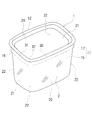
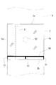
- the container with a shrink label shown in FIG. 1 is a square container with a shrink label in which a shrink label 2 is attached to a square container 1 having a side surface 11 having a square shape in cross section.
- the shrink label 2 is indicated by a two-dot chain line.
- the container 1 is formed from various synthetic resins by injection molding, but may be formed by blow molding or sheet molding.
- the container 1 has a bottomed rectangular tube shape with an upper surface opening, and includes a bottom surface portion 10, a side surface portion 11 having a rectangular shape in a cross-sectional view rising upward from a peripheral edge portion of the bottom surface portion 10, and the side surface portion 11. And a flange 12 projecting outward from the upper end portion.
- the bottom surface portion 10 has a rectangular shape in accordance with the side surface portion 11 having a rectangular shape in cross section.
- the side surface portion 11 is formed to rise upward from the peripheral edge portion of the bottom surface portion 10, and is roughly divided into two regions, upper and lower. That is, the side surface portion 11 is a side surface main portion 15 via a side surface main portion 15 that is a lower region and rising from the bottom surface portion 10, and a step region 16 that is an upper region and is outward from the side surface main portion 15. And the side surface upper step portion 17 extending upward.
- the side main part 15 occupies most of the area of the side part 11, and is formed in a tapered shape that gradually spreads upward from the bottom part 10. However, the slope of the side main part 15 is about several degrees.
- the side main part 15 includes four main wall surfaces 20 and 21. That is, the side main part 15 includes a pair of main wall surfaces 20 on the long side and a pair of main wall surfaces 21 on the short side.
- the pair of main wall surfaces 21 on the short side is the surfaces that are the left and right side surfaces of the container 1, and the pair of main wall surfaces 20 on the long side are the surfaces that serve as the front and back surfaces of the container 1.
- the four main wall surfaces 20 and 21 are formed in a flat shape or a shape bulging slightly toward the outside.
- angular part 22 between adjacent main wall surfaces 20 and 21 is formed in the cross-sectional view circular arc shape.
- the side surface upper step portion 17 is expanded one step outward from the side surface main portion 15, and the vertical dimension thereof is smaller than the side surface main portion 15 and has a strip shape.
- the side surface main portion 15 is tapered, while the side surface upper step portion 17 stands substantially upright, and the flange 12 is formed substantially horizontally at the upper end thereof over the entire circumference.
- the side upper step portion 17 is also provided with four upper wall surfaces 30 and 31. That is, the side surface upper step portion 17 includes a pair of upper wall surfaces 30 on the long side and a pair of upper wall surfaces 31 on the short side.
- the pair of upper side walls 31 on the short side is located above the main wall 21 on the short side of the side main part 15 and constitutes the left and right side surfaces of the container 1 together with the main wall 21.
- the upper wall surface 30 is positioned above the main wall surface 20 on the long side of the side surface main portion 15 and constitutes the front and back surfaces of the container 1 together with the main wall surface 20.
- the four wall surfaces constituting the side surface portion 11 are constituted by the main wall surfaces 20 and 21 of the side surface main portion 15 and the upper wall surfaces 30 and 31 of the side surface upper step portion 17.
- the four upper wall surfaces 30 and 31 are also formed in a shape that is flat or slightly bulged outwardly in the side upper step portion 17.
- angular part 32 between adjacent upper wall surfaces 30 and 31 is formed in circular cross sectional view arc shape.
- a cylindrical shrink label 2 is attached to the side surface 11 of the container 1.
- the shrink label 2 covers substantially the entire side surface portion 11, and the upper end edge 2 a reaches the substantially upper end of the side surface upper step portion 17. That is, the upper end edge 2 a of the shrink label 2 is located substantially directly below the flange 12. Further, the lower predetermined region of the shrink label 2 extends from the side surface portion 11 to the bottom surface portion 10 to cover the peripheral edge portion of the bottom surface portion 10, and the lower end edge 2 b of the shrink label 2 is located on the bottom surface portion 10 of the container 1. Yes.
- the portion of the shrink label 2 that covers the peripheral edge of the bottom surface portion 10 is a bottom surface covering portion 40.
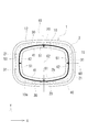
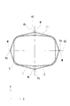
- the bottom surface covering portion 40 includes four side portions 41 and 42 corresponding to the four wall surfaces of the side surface portion 11 of the container 1. Since the side surface portion 11 of the container 1 is rectangular in a cross-sectional view, the four side portions 41 and 42 of the bottom surface covering portion 40 are composed of a pair of long side portions 41 and a pair of short side portions 42. In FIG. 3 and the like, the direction in which the pair of short sides 42 faces each other is the X axis, and the direction in which the pair of long sides 41 faces each other is the Y axis.
- a mark for inspecting the positional deviation of the shrink label 2 with respect to the container 1 is formed on the bottom surface covering portion 40. Specifically, the vertical inspection mark 50 for inspecting the positional deviation in the vertical direction (axial direction) of the shrink label 2 with respect to the container 1 and the positional deviation in the horizontal direction (circumferential direction) of the shrink label 2 with respect to the container 1 are detected. A horizontal inspection mark 51 for inspection is formed. The vertical inspection mark 50 and the horizontal inspection mark 51 are shown as black areas in the drawing.
- the vertical inspection mark 50 is formed in a line shape along the lower end edge 2b of the shrink label 2 and is formed in a ring shape as a whole because it is formed over the entire circumference. More specifically, the vertical inspection mark 50 is formed in parallel with the lower end edge 2b at a location separated from the lower end edge 2b of the shrink label 2 by about several millimeters, and its thickness is arbitrary but about 1 mm, for example.
- the lateral inspection mark 51 is formed in a linear shape extending in a direction substantially orthogonal to the lower end edge 2b of the shrink label 2, and therefore, both side edges thereof are substantially about the lower end edge 2b of the shrink label 2. It extends in the orthogonal direction.
- the lateral inspection mark 51 is formed at one location on each of the four sides 41 and 42 constituting the bottom surface covering portion 40, and both are formed in the lateral central region of the sides 41 and 42. . That is, the horizontal inspection marks 51 formed on the pair of long side portions 41 respectively extend in the Y-axis direction and face each other, and the horizontal inspection marks 51 formed on the pair of short side portions 42 respectively It extends in the axial direction and faces each other.
- the horizontal inspection mark 51 has the design position at the center in the horizontal direction of the side portions 41 and 42. Therefore, the horizontal inspection mark 51 formed on each of the pair of long side portions 41 is in a position that bisects the entire circumference of the cylindrical shrink label 2, and is formed on each of the pair of short side portions 42. Similarly, the horizontal inspection mark 51 is at a position that bisects the entire circumference of the cylindrical shrink label 2.
- These horizontal inspection marks 51 are formed so as to protrude from the vertical inspection mark 50 inward, that is, toward the lower end edge 2b of the shrink label 2, and are formed integrally with the vertical inspection mark 50. ing.
- the tip of the horizontal inspection mark 51 is slightly separated from the lower end edge 2b of the shrink label 2 so as not to reach it. Further, the length of the horizontal inspection mark 51 (that is, the protruding amount from the vertical inspection mark 50) is, for example, about several mm to several tens of mm.
- reference numeral 60 denotes a center line extending in the X-axis direction by connecting the horizontal central portions of the pair of short side portions 42
- reference numeral 61 denotes the horizontal central portions of the pair of long side portions 41.
- a center line extending in the Y-axis direction is shown
- reference numeral 62 denotes an intersection where the center line 60 in the X-axis direction and the center line 61 in the Y-axis direction intersect.
- FIG. 3 shows a state in which the shrink label 2 is accurately attached at a predetermined position
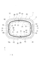
- FIG. 4 shows a state in which the shrink label 2 is attached while being displaced by a predetermined amount in the lateral direction.
- FIG. 6 to 8 also show the case where the shrink label 2 is mounted with a predetermined amount of positional deviation as in FIG.
- the horizontal inspection marks 51 formed on the pair of long side portions 41 are both positioned on the center line 61 in the Y-axis direction and formed on the pair of short side portions 42 by design. All the horizontal inspection marks 51 are located on the center line 60 in the X-axis direction.
- the horizontal inspection mark 51 formed on the pair of long side portions 41 is located in the X-axis direction from the center line 61 in the Y-axis direction as shown in FIG.
- the directions of the eccentricity are opposite to each other, and is in a point-symmetrical positional relationship with respect to the intersection 62, and in the cylindrical shrink label 2 is in a positional relationship facing 180 degrees. is there.
- the lateral inspection mark 51 formed on the pair of short sides 42 is also present at a position deviated by a predetermined amount in the Y-axis direction from the center line 60 in the X-axis direction, and the directions of the eccentricity are opposite to each other.
- it is in a point-symmetrical positional relationship with respect to the intersection point 62, and this is also in a positional relationship that is opposed to the cylindrical shrink label 2 by 180 degrees.
- all the four lateral inspection marks 51 are present at positions shifted by a predetermined amount in the same circumferential direction (lateral direction) with respect to the center line 60 in the X-axis direction and the center line 61 in the Y-axis direction. Become.
- the shrink label 2 before being attached to the container 1 is shown in FIG.
- the shrink label 2 is formed, for example, by cutting a long raw film into a predetermined width to form a long shrink film, and bonding both side edges of the long shrink film into a cylindrical shape. It is formed by forming a long cylindrical label long body 5 as shown by a two-dot chain line in FIG. 5 and cutting the long label body 5 every predetermined length.
- reference numeral 3 indicates an overlapping portion where both side edges of the shrink film are bonded together.
- fold 4a is each formed in the both-sides edge of the label long body 5 of a flat state.
- a predetermined region on the lower end side in the axial direction of the shrink label 2 is a portion that becomes a bottom surface covering portion 40 that covers the bottom surface portion 10 of the container 1, and a vertical direction inspection mark 50 and a horizontal direction inspection mark 51 are formed in this portion.
- the vertical inspection mark 50 extends in the circumferential direction in parallel with the lower end edge 2b of the shrink label 2 and is formed over the entire circumference.
- the horizontal inspection mark 51 shrinks from the vertical inspection mark 50 toward the lower end edge 2b. It is formed so as to protrude in the axial direction of the label 2.
- the cylindrical shrink label 2 includes a pair of lateral inspection marks 51 respectively formed at two positions that bisect the entire circumference of the shrink label 2, and the pair of lateral inspection marks 51.
- a pair of lateral inspection marks 51 formed at two positions that further bisect the space are provided. That is, the horizontal inspection marks 51 are formed at four positions on the shrink label 2 that divide the entire circumference into four equal parts. Therefore, a total of four horizontal inspection marks 51 are formed on the shrink label 2. ing. Then, a pair of lateral inspection marks 51 respectively formed at two positions that bisect the entire circumference of the shrink label 2 are positioned corresponding to the pair of long side portions 41 of the bottom surface covering portion 40, and The pair of lateral inspection marks 51 formed at two positions that further bisect the pair of lateral inspection marks 51 are positioned corresponding to the pair of short sides 42 of the bottom surface covering portion 40. Is located.
- the shrink label 2 has a display printing layer such as letters and designs laminated on the inner surface of the film substrate, a white printing layer is laminated on the inner surface of the display printing layer, and the display printing layer is externally passed through the transparent film substrate. It has a so-called back printing configuration for visual recognition.
- the display print layer and the white print layer can be formed on the above-described raw film by, for example, a printing technique such as gravure printing, and the vertical inspection mark 50 and the horizontal inspection mark 51 are formed at the time of the formation. Can do.
- the vertical inspection mark 50 and the horizontal inspection mark 51 are preferably black.
- the surrounding color is preferably white so that the vertical inspection mark 50 and the horizontal inspection mark 51 are formed in a high contrast state, and therefore, the white print layer is used as the background layer. It is preferable to form the vertical inspection mark 50 and the horizontal inspection mark 51 together with the display print layer on the front side.
- Various films can be used for the film substrate of the shrink label 2, for example, polyolefins such as polyethylene (PE) and polypropylene (PP), polyesters such as polyethylene terephthalate (PET) and polybutylene terephthalate (PBT), and polystyrenes.
- a film made of (PS) and a resin such as polylactic acid (PLA), polyamide, and polyvinyl chloride can be used.
- polyester-based, polylactic acid-based, and polystyrene-based films are preferable because they have appropriate shrinkage stress and high transparency, and polyester-based films are particularly preferable.
- the film containing the resin mixture which mixed 2 or more types of these resin can also be used, and the laminated
- contracts in the circumferential direction in the cylindrical shrink label 2 can be used, the biaxially stretched film which shrink
- the heat shrinkage rate in the main stretching direction of the film that is, the heat shrinkage rate in the circumferential direction of the cylindrical shrink label 2 is preferably 20 to 80% when immersed in hot water at 90 ° C. for 10 seconds, 30 to 30%. 80% is particularly preferable.
- the side surface main portion 15 of the container 1 has a tapered shape spreading upward, and the side surface upper step portion 17 is one step larger than the side surface main portion 15, so that the shrinkage amount of the shrink label 2 is
- the side surface upper step portion 17 is the smallest, and the shrinkage amount in the side surface main portion 15 is larger than that in the side surface upper step portion 17 and increases toward the lower side. Therefore, it is preferable to apply a delayed tack type adhesive to the upper predetermined region on the inner surface of the shrink label 2 by, for example, gravure printing.
- the adhesive is activated by heat during shrinking, the shrink label 2 is bonded to the upper side step portion 17, thereby preventing the shrink label 2 from being displaced downward.
- the adhesive may be formed on the upper predetermined region of the inner surface of the shrink label 2 as desired.
- a predetermined amount is used instead of continuously forming the application part to which the adhesive is applied in the circumferential direction over the entire circumference. It is preferable to alternately form the length of the application portion and the non-application portion where the adhesive is not applied in the circumferential direction, thereby preventing blocking of the inner surfaces when the shrink label 2 is folded flat. it can.
- the application part and the non-application part are alternately formed in the circumferential direction, two rows along the circumferential direction are formed in the upper and lower rows, and the application parts are arranged in a staggered manner in the upper row and the lower row. It is preferable to form as described above.
- the outline of the manufacturing method of the container with the shrink label will be described.
- the process of covering the shrink label 2 on the side surface portion 11 of the container 1 and the vertical direction inspection mark 50 and the horizontal direction inspection mark 51 on the bottom surface covering portion 40 of the shrink label 2 are described.
- the container 1 is conveyed upside down, that is, conveyed by conveying means such as a conveyor so that the bottom surface portion 10 faces upward, and the shrink label 2 is put on the side surface portion 11 of the container 1 from above.
- the shrink label 2 placed on the side surface portion 11 of the container 1 protrudes from the bottom surface portion 10 of the container 1 by a predetermined length, and the vertical direction inspection mark 50 and the horizontal direction inspection mark 51 are located in the protruding portion. Then, the shrink label 2 is heated by heating means such as a hot air heater, and the shrink label 2 is thermally contracted to be in close contact with the side surface portion 10, and the above-described protruding portion mainly covers the bottom surface portion 10 of the container 1. It becomes. Then, it progresses to an inspection process.
- the container 1 to which the shrink label 2 is attached is conveyed in an upside down state. That is, the container 1 is transported by transport means such as a conveyor so that the bottom surface portion 10 faces upward and the flange 12 faces downward.
- Illumination means for irradiating light onto the container 1 from above and imaging means for imaging the container 1 from above are arranged at predetermined locations on the transport path, and the shrink label 2 is taken from the image data captured by the imaging means.
- Check for misalignment Specifically, a shrink label 2 that is not substantially displaced and is accurately mounted at a predetermined position is conveyed as a reference product, and is imaged by an imaging means.
- the position of the direction inspection mark 50 and the position of the horizontal direction inspection mark 51 are measured and used as a reference value, and whether or not the amount of positional deviation from the reference value is within a predetermined range, that is, whether it is within an allowable range. If it is within the allowable range, it is determined to be OK, and if it is outside the allowable range, it is determined to be NG.
- the OK product is transported as it is, and the NG product is removed from the transport path.
- Fig. 6 and Fig. 7 show the status of the vertical misalignment inspection.
- the position of the inner edge of the vertical inspection mark 50 and the position of the peripheral edge 10a of the bottom surface portion 10 of the container 1 are discriminated and specified from the density difference, respectively, and the separation distance therebetween Is calculated.
- the measurement point P1 on the inner edge of the vertical inspection mark 50 and the measurement point P2 on the peripheral edge 10a of the bottom surface portion 10 are indicated by circles, but the measurement points P1 and P2 are the side portions 41 and 42, respectively.
- a plurality of locations are provided in each, and a region other than the corner portion between the side portions 41 and 42 is set as a measurement region.
- the separation distance (AX) in the X-axis direction is calculated at the short side portion 42, and the separation distance (AY) in the Y-axis direction at the long side portion 41. Is calculated. Then, the maximum value and the minimum value of the separation distance are obtained in each of the side portions 41 and 42, and it is determined whether or not each of the maximum value and the minimum value is within the allowable range. If the shrink label 2 is displaced to the lower side, that is, the bottom surface portion 10 side with respect to the container 1, the separation distance increases, and conversely, the shrink label 2 is displaced to the upper side, that is, the flange 12 side with respect to the container 1.
- the separation distance becomes smaller. Accordingly, by measuring the separation distance from the inner edge of the vertical inspection mark 50 to the peripheral edge 10a of the bottom surface portion 10, the vertical displacement of the shrink label 2 with respect to the container 1 can be inspected. In addition, since the separation distance is measured at each of the side portions 41 and 42, not only when the shrink label 2 is entirely displaced but also when the shrink label 2 is inclined with respect to the container 1. Even it can be detected. Furthermore, since there are a plurality of measurement points P1 and P2 in each of the side portions 41 and 42, the bottom surface covering portion 40 of the shrink label 2 seems to be locally distorted at specific locations of the long side portion 41 and the short side portion 42. Even in this case, since the state appears at the maximum value and the minimum value, it can be easily inspected.
- the lateral displacement of the shrink label 2 with respect to the container 1 is inspected as follows. That is, the center position of the horizontal inspection mark 51 is specified from the imaging data, and its XY coordinates are obtained.
- the center position of the horizontal inspection mark 51 is the center position in the protruding direction from the vertical inspection mark 50 and the center position in the width direction of the horizontal inspection mark 51.
- the distance (BX) in the X-axis direction between the two horizontal inspection marks 51 is calculated, and the distance is relative to the reference value. Check whether it is within the allowable range.
- the distance (BY) in the Y-axis direction between the lateral inspection marks 51 is calculated, and the distance is within an allowable range with respect to the reference value. Inspect whether or not.
- the lateral displacement of the shrink label 2 is inspected from the distance between the lateral inspection marks 51 provided on the pair of opposing side portions 41 and 42 in this way, the lateral direction of the shrink label 2 is The misalignment appears in the measured value twice as large, and a highly accurate inspection can be performed.
- inspection can be performed in two directions on the long side portion 41 side and the short side portion 42 side, the inspection can be performed with higher accuracy.
- the horizontal inspection mark 51 is arranged in the central region in the horizontal direction of each of the side portions 41 and 42, there is a variation in measurement compared to the case where it is arranged near the corner portion between the side portions 41 and 42. Hard to occur.
- the container 1 When inspecting the vertical position deviation and the horizontal position deviation, the container 1 itself rotates with respect to the imaging means, and the opposing direction of the short side portions 42 is inclined with respect to the X axis of the imaging means. In such a case, tilt correction may be performed.
- the design position of the horizontal inspection mark 51 may not be on the center lines 60 and 61, and each side If it exists in the horizontal direction center area
- the design position of the horizontal inspection mark 51 may be a position shifted by a predetermined amount from the center lines 60 and 61 in the horizontal direction (circumferential direction). Even in such a case, the distance in the X-axis direction (BX) between the two horizontal inspection marks 51 and the distance in the Y-axis direction (BY) between the two horizontal inspection marks 51 are measured and calculated, and the distance is the reference value.
- the directionality of the lateral displacement of the shrink label 2 is also inspected. May be. For example, when the distance (BX) in the X-axis direction and the distance (BY) in the Y-axis direction are smaller than the reference value, the shrink label 2 is rotated clockwise in FIG. .
- the vertical inspection mark 50 is formed in a ring shape over the entire circumference, but it may not be formed over the entire circumference.
- the vertical inspection mark 50 may be formed in a linear shape having a predetermined length along the lower end edge 2 b of the shrink label 2.
- the vertical inspection mark 50 is formed with a thicker line, the vertical inspection mark 50 is not partially formed, a white portion is formed, and the white portion is formed as the horizontal inspection mark 51. It is good.
- the vertical inspection mark 50 is not partially formed in the horizontal center of each of the long side portion 41 and the short side portion 42, and a white portion is formed.
- the cut-out portion may be used as the horizontal inspection mark 51.
- the left and right side edges of the horizontal inspection mark 51 composed of the white portions are also the side edges (circumferential edges) of the left and right vertical inspection marks 50. Measure.
- the vertical direction inspection mark 50 and the horizontal direction inspection mark 51 composed of white portions may be formed in a high contrast state as in the above embodiment. In this case as well, the side edge of the horizontal inspection mark 51 extends in a direction substantially orthogonal to the lower end edge 2b of the shrink label 2, so that the position of the side edge can be easily specified.
- the center position of the horizontal inspection mark 51 is specified from the imaging data, its XY coordinates are obtained, and the distance (BX) between the two horizontal inspection marks 51 in the X-axis direction and the Y-axis direction.
- the distance (BY) may be calculated, but the position of one of the left and right side edges of the horizontal inspection mark 51 may be detected.
- FIG. 9 the position of one side edge of the lateral inspection mark 51 in one long side portion 41 and the position of one side edge of the lateral inspection mark 51 in the other long side portion 41 are respectively shown.
- the distance (BX) in the X-axis direction between both side edges is calculated and compared with a reference value.
- FIG. 9 the distance (BX) between both side edges is calculated and compared with a reference value.
- the position of one side edge of the lateral inspection mark 51 in one short side portion 42 and the position of one side edge of the lateral inspection mark 51 in the other short side portion 42 are detected. Then, the distance (BY) between the side edges in the Y-axis direction is calculated and compared with the reference value. Then, by determining OK / NG from the amount of deviation from the reference value, it is possible to inspect the lateral displacement of the shrink label 2. In this case as well, the positional deviation of the shrink label 2 in the vertical direction can be inspected by measuring the distance between the inner edge of the vertical inspection mark 50 and the peripheral edge 10a of the bottom surface portion 10 in the same manner as described above. . In FIG.
- the vertical inspection mark 50 is not provided at the corner portion, but may be provided at the corner portion.
- the horizontal inspection mark 51 including a white portion may be provided only on one of the long side portion 41 and the short side portion 42. Alternatively, the positions of the left and right side edges of the horizontal inspection mark 51 may be detected.
- the vertical inspection mark 50 may be formed in a ring shape, and a rectangular horizontal inspection mark 51 may be formed at a predetermined position in the circumferential direction.
- the horizontal inspection mark 51 can be formed at one place on the long side portion 41 and one place on the short side portion 42.
- the rectangular lateral inspection mark 51 has a portion protruding inward from the longitudinal inspection mark 50, and the length of the side edge of the lateral inspection mark 51 can be easily secured. Measurement accuracy can be improved.
- the distance (BY) in the Y-axis direction By measuring the distance (BY) in the Y-axis direction and comparing it with a reference value, it is possible to inspect the lateral displacement of the shrink label 2. It should be noted that any of the side edges of the lateral inspection mark 51 may be measured, both side edges may be measured, or the center position of the lateral inspection mark 51 may be specified. Good.
- the distance from the horizontal inspection mark 51 to the outer edge of the flange 12 may be measured and inspected, and this point is the same in the embodiments shown in FIGS. Note that the distance to the side surface portion 11 (for example, the side wall upper step portion 17) instead of the outer edge of the flange 12 may be measured.
- the horizontal inspection mark 51 is formed on the bottom surface covering portion 40, it is easy to focus, and therefore, a highly accurate inspection with little variation is possible.
- FIG. 8 a method for measuring the distance between a pair of opposing horizontal inspection marks 51, and from the horizontal inspection mark 51 to the container 1 as shown in FIG.
- You may use together with the method of measuring the distance to an edge (for example, the outer edge of the flange 12).
- an edge for example, the outer edge of the flange 12
- the shrink label 2 is almost entirely covered as shown in FIG. It will be in the state where it shifted to the horizontal direction uniformly.
- the shrink label 2 is displaced in the lateral direction substantially uniformly over the entire circumference, as shown in FIGS.
- a pair of lateral surfaces facing in the Y-axis direction are used.
- a method of measuring the distance (BX) in the X-axis direction between the direction inspection marks 51 and the distance (BY) in the Y-axis direction between the pair of lateral inspection marks 51 facing in the X-axis direction is preferable. High measurement accuracy.
- the design of the shrink label 2 Will be displaced toward a specific location where the amount of contraction is large.
- a pair of lateral inspection marks 51 facing in the Y-axis direction that is, a pair of long sides 41 Both the direction inspection marks 51 are displaced toward the right side in the drawing.
- the shrink label 2 is even over the entire circumference. Even if it is a case where the shrinkage
- the pair of horizontal inspection marks 51 are flattened. You may arrange
- the horizontal inspection marks 51 are formed at two positions that bisect the pair of horizontal inspection marks 51, that is, the entire circumference of the cylindrical shrink label 2 is divided into four parts. In the case where the horizontal inspection marks 51 are respectively formed at the four positions to be divided, the two horizontal inspection marks 51 are formed on both folds 4a of the cylindrical shrink label 2 in a flat folded state.
- Each of the two horizontal inspection marks 51 may be arranged at the center in the width direction of the cylindrical shrink label 2 that is folded flat.
- the two lateral inspection marks 51 located on both folds 4a are located on one of the pair of long side portions 41 and the pair of short side portions 42 of the bottom surface covering portion 40, and are folded in a flat shape.
- Two horizontal inspection marks 51 positioned at the center in the width direction of a certain cylindrical shrink label 2 are positioned on the other of the pair of long side portions 41 and the pair of short side portions 42 of the bottom surface covering portion 40.
- the two horizontal inspection marks 51 positioned on the side portion 41 are positioned at the center in the width direction of the cylindrical shrink label 2 that is folded flat.
- the long label body 5 formed by bonding both side edges of a long shrink film having a predetermined width is flattened, wound into a roll, and stored and transported. . Therefore, the creases 4a are respectively formed on both side edges of the flat label long body 5 as shown in FIG. Then, before the long label body 5 fed out from the roll is cut every predetermined length, there is a case where a folding process is performed to return the long label body 5 in the course of the travel path in order to easily cover the container 1. . In the folding process, the long label body 5 in the flat state is once opened, and the both side edges in the flat state are newly folded in the flat state so as to be close to each other as indicated by an arrow ⁇ shown in FIG. It is processing.
- two long folds 4b are formed in the long label body 5 by this folding process, and a total of four folds 4a and 4b are formed in the axial direction together with the original two folds 4a. Will be formed along.
- the folds 4a and 4b are formed at intervals of about 90 degrees in the circumferential direction, but are positioned at the pair of short sides 42 as described above, for example, at the position of the original two folds 4a.
- two new horizontal inspection marks 51 positioned on the pair of long side portions 41 are provided on the two new folds 4b.
- a portion indicated by a symbol M indicates a portion where the lateral inspection mark 51 is formed on the entire circumference of the long label body 5 and the shrink label 2.
- the label long body 5 is newly folded in a direction orthogonal to the original flat state to be in a flat state, it is cut into predetermined lengths to form individual cylindrical shrink labels 2. Is done. And if the shrink label 2 in which the four folds 4a and 4b are formed is expanded by an opener and the side surface portion 11 of the container 2 is covered with the shrink label 2 from the bottom surface portion 10 side, as shown in FIG. Since the folds 4 a and 4 b are formed in the portion 2, the portion between the adjacent folds 4 a and 4 b closely adheres to the side surface portion 11, particularly the corner portion 22 of the container 1.
- the horizontal inspection mark 51 can be easily positioned at the center of the long side portion 41 and the short side portion 42.
- the overlapping portion 3 is preferably formed at a position different from the folding positions 4a and 4b, and the lateral inspection mark 51 is preferably formed at a position different from the overlapping portion 3. Further, the folding process as described above is not essential and may be omitted.
- the shrink label 2 has a specific display portion 80 that is to be particularly accurately located at a predetermined position on the side surface portion 11 of the container 1 such as a main design or a logo mark.
- the horizontal inspection mark 51 it is also preferable to arrange the horizontal inspection mark 51 at a position corresponding to the specific display unit 80 (for example, the same position in the horizontal direction as the display unit 80) in the entire circumference of the shrink label 2.
- the corner portion 22 of the side surface portion 11 of the container 1 has an arc shape in cross section, that is, an outwardly convex curved surface. As shown in FIG. 17, the corner portion 22 of the side surface portion 11 may be a flat surface.
- the present invention can be applied to various square shapes such as a square shape in cross section and a pentagon shape in cross section. Further, even if the container 1 has a shape other than a square shape such as an ellipse, it is similarly effective when the lateral displacement of the shrink label 2 becomes a problem.
- the horizontal inspection marks 51 are formed at two locations on the major axis 70 of the ellipse and two locations on the minor axis 71 in the bottom surface coating portion 40 of the shrink label 2. A total of four locations are provided. For example, when the major axis 70 of the ellipse is parallel to the X axis and the minor axis 71 of the ellipse is parallel to the Y axis, the positional deviation of the lateral inspection mark 51 can be easily measured.
- the horizontal direction inspection mark 51 should just be arrange
- the cross-sectional view ellipse in the bottom surface part 10 or the side surface part 11 of the container 1 does not have to be a mathematically exact ellipse, includes an oval shape, and a straight line is partially formed like an oval shape or an oval shape. The shape may be included.
- the bottom surface portion 10 of the container 1 A center line passing through the center and along the longitudinal direction of the bottom surface portion 10 of the container 1 is a long axis, and passing through the center of the bottom surface portion 10 of the container 1 and along the short direction of the bottom surface portion 10 of the container 1. It is sufficient that the lateral inspection mark 51 is formed in at least one of the total four locations of two locations on the major axis and two locations on the minor axis in the bottom surface covering portion 40.
- the container 1 without the flange 12 may be used, for example, a square PET bottle.
- the shape of the lateral inspection mark 51 can be variously changed, and may be a shape other than a shape extending in a direction substantially orthogonal to the lower end edge 2b of the shrink label 2, and may be a circle or an ellipse. It may be a shape, a rhombus, a parallelogram, or the like. Regardless of the shape of the horizontal inspection mark 51, the position of the horizontal inspection mark 51 (for example, the center position) can be specified to inspect the lateral displacement of the shrink label 2. Note that a rhombus or a parallelogram having a straight line is more preferable than a circle or an ellipse because detection is easier.
- UV ink may be used for the vertical inspection mark 50 and the horizontal inspection mark 51.
- the vertical inspection mark 50 and the horizontal inspection mark 51 may be UV emission marks that are always transparent but emit light when irradiated with ultraviolet rays.
- the label is a transparent shrink label 2, transparent container 1, transparent contents, etc., and you do not want to impair the transparency, use a UV emission mark. Is preferred.
- a black mark on a white background white background
- a yellow or white mark may be used on a black background (black background).
- a black mark may be provided on a transparent label substrate with the white container 1 as a background.
- a black print layer may be provided on a transparent label base material, and a transparent mark having a cut shape such as a cut character that does not partially provide the black print layer may be used.
Abstract
Description
2 シュリンクラベル
2a 上端縁
2b 下端縁
3 重ね合わせ部
4a 折り目
4b 折り目
5 ラベル長尺体
10 底面部
10a 周縁
11 側面部
12 フランジ
15 側壁主部
16 段差部
17 側壁上段部
20 主壁面
21 主壁面
22 角部
30 上部壁面
31 上部壁面
32 角部
40 底面被覆部
41 長辺部
42 短辺部
50 縦方向検査マーク
51 横方向検査マーク
60 中心線
61 中心線
62 交点
70 長軸
71 短軸
80 表示部
P1 測定ポイント
P2 測定ポイント DESCRIPTION OF
Claims (10)
- 容器の側面部から底面部にかけてシュリンクラベルが装着されたシュリンクラベル付き容器であって、
容器の底面部を覆っているシュリンクラベルの底面被覆部には、容器に対するシュリンクラベルの横方向の位置ずれを検査するための横方向検査マークが設けられていることを特徴とするシュリンクラベル付き容器。 A container with a shrink label on which a shrink label is attached from the side to the bottom of the container,
A container with a shrink label, characterized in that a lateral inspection mark for inspecting a lateral displacement of the shrink label with respect to the container is provided on the bottom surface covering portion of the shrink label covering the bottom surface of the container. . - 横方向検査マークは、シュリンクラベルの下端縁に対して略直交する方向に延びる側縁を有している請求項1記載のシュリンクラベル付き容器。 The container with a shrink label according to claim 1, wherein the lateral inspection mark has a side edge extending in a direction substantially orthogonal to a lower end edge of the shrink label.
- 横方向検査マークは、シュリンクラベルの下端縁に対して略直交する方向に延びる線状である請求項2記載のシュリンクラベル付き容器。 3. The container with a shrink label according to claim 2, wherein the horizontal inspection mark is a line extending in a direction substantially orthogonal to the lower end edge of the shrink label.
- 容器の側面部が横断面視矩形であり、該側面部の四つの壁面に対応して底面被覆部は四つの辺部から構成され、該四つの辺部のうち少なくとも一つの辺部の横方向中央領域に横方向検査マークが設けられている請求項1乃至3の何れかに記載のシュリンクラベル付き容器。 The side surface of the container is rectangular in cross-sectional view, and the bottom surface covering portion is composed of four sides corresponding to the four wall surfaces of the side surface, and the lateral direction of at least one side of the four sides The container with a shrink label according to any one of claims 1 to 3, wherein a lateral inspection mark is provided in a central region.
- 四つの辺部のうち対向する一対の辺部に横方向検査マークがそれぞれ設けられている請求項4記載のシュリンクラベル付き容器。 The container with a shrink label according to claim 4, wherein a lateral inspection mark is provided on each of a pair of opposing sides of the four sides.
- 容器の側面部が横断面視楕円形であり、底面被覆部において長軸上に位置する二箇所と短軸上に位置する二箇所の合計四箇所のうち少なくとも一箇所に横方向検査マークが設けられている請求項1乃至3の何れかに記載のシュリンクラベル付き容器。 The side surface of the container is oval in cross-sectional view, and a horizontal inspection mark is provided in at least one of the four locations in total, two on the bottom axis and two on the short axis. A container with a shrink label according to any one of claims 1 to 3.
- 底面被覆部には、容器に対するシュリンクラベルの縦方向の位置ずれを検査するための縦方向検査マークがシュリンクラベルの下端縁に沿って延びる線状に形成され、横方向検査マークの少なくとも一部が縦方向検査マークの内側に位置する請求項1乃至6の何れかに記載のシュリンクラベル付き容器。 A vertical inspection mark for inspecting the vertical displacement of the shrink label with respect to the container is formed on the bottom surface covering portion in a linear shape extending along the lower edge of the shrink label, and at least a part of the horizontal inspection mark is formed. The container with a shrink label according to any one of claims 1 to 6, which is located inside a longitudinal inspection mark.
- 容器の側面部から底面部にかけて装着されるシュリンクラベルであって、
容器の底面部を覆う部分に、容器に対するシュリンクラベルの横方向の位置ずれを検査するための横方向検査マークが設けられていることを特徴とするシュリンクラベル。 A shrink label that is attached from the side to the bottom of the container,
The shrink label characterized by the horizontal direction inspection mark for inspecting the position shift of the shrink label of the shrink label with respect to a container being provided in the part which covers the bottom face part of a container. - シュリンクラベルの全周を二等分する二箇所の位置にそれぞれ横方向検査マークが設けられている請求項8記載のシュリンクラベル。 The shrink label according to claim 8, wherein a lateral inspection mark is provided at each of two positions that bisect the entire circumference of the shrink label.
- 横方向検査マークが設けられたシュリンクラベルを容器の側面部に被せる工程と、容器の底面部を覆うシュリンクラベルの部分に横方向検査マークが位置するようにシュリンクラベルを熱収縮させて容器に装着させる工程と、該容器に装着されたシュリンクラベルの横方向検査マークの位置を測定することにより、容器に対するシュリンクラベルの横方向の位置ずれを検査する工程とを備えていることを特徴とするシュリンクラベル付き容器の製造方法。 Place the shrink label with the horizontal inspection mark on the side of the container, and attach the shrink label to the container by heat shrinking so that the horizontal inspection mark is positioned on the shrink label covering the bottom of the container And a step of inspecting the lateral displacement of the shrink label with respect to the container by measuring the position of the lateral inspection mark of the shrink label attached to the container. A method for manufacturing a labeled container.
Priority Applications (3)
| Application Number | Priority Date | Filing Date | Title |
|---|---|---|---|
| US14/433,430 US20150246750A1 (en) | 2012-10-04 | 2013-10-04 | Container with shrink-fit label, shrink-fit label, and manufacturing method for container with shrink-fit label |
| EP13844134.0A EP2910480A4 (en) | 2012-10-04 | 2013-10-04 | Container with shrink-fit label, shrink-fit label, and manufacturing method for container with shrink-fit label |
| JP2014539844A JP6369329B2 (en) | 2012-10-04 | 2013-10-04 | Shrink-labeled container, shrink-label, and manufacturing method of shrink-labeled container |
Applications Claiming Priority (2)
| Application Number | Priority Date | Filing Date | Title |
|---|---|---|---|
| JP2012-222359 | 2012-10-04 | ||
| JP2012222359 | 2012-10-04 |
Publications (1)
| Publication Number | Publication Date |
|---|---|
| WO2014054780A1 true WO2014054780A1 (en) | 2014-04-10 |
Family
ID=50435099
Family Applications (1)
| Application Number | Title | Priority Date | Filing Date |
|---|---|---|---|
| PCT/JP2013/077080 WO2014054780A1 (en) | 2012-10-04 | 2013-10-04 | Container with shrink-fit label, shrink-fit label, and manufacturing method for container with shrink-fit label |
Country Status (4)
| Country | Link |
|---|---|
| US (1) | US20150246750A1 (en) |
| EP (1) | EP2910480A4 (en) |
| JP (1) | JP6369329B2 (en) |
| WO (1) | WO2014054780A1 (en) |
Cited By (2)
| Publication number | Priority date | Publication date | Assignee | Title |
|---|---|---|---|---|
| JP2017030760A (en) * | 2015-07-29 | 2017-02-09 | 株式会社フジシール | Inspection device, inspection method, container with label, and shrink label |
| JP2019194096A (en) * | 2018-05-01 | 2019-11-07 | 株式会社ナベル | Inspection equipment of label |
Citations (6)
| Publication number | Priority date | Publication date | Assignee | Title |
|---|---|---|---|---|
| JP2000339459A (en) * | 1999-05-25 | 2000-12-08 | Sharp Corp | Picture processor |
| JP2005077583A (en) | 2003-08-29 | 2005-03-24 | Toppan Printing Co Ltd | Label and labeling inspection method |
| JP2005119706A (en) | 2003-10-16 | 2005-05-12 | Kirin Techno-System Corp | Label inspection device |
| JP2010168115A (en) * | 2008-12-22 | 2010-08-05 | Showa Denko Kk | Method and system for manufacturing resin-made container, and container for beverage |
| JP4627257B2 (en) | 2005-12-16 | 2011-02-09 | 株式会社フジシールインターナショナル | Inspection device, container with shrink label and shrink label |
| WO2011121732A1 (en) * | 2010-03-30 | 2011-10-06 | 株式会社フジシールインターナショナル | Label attachment device |
Family Cites Families (14)
| Publication number | Priority date | Publication date | Assignee | Title |
|---|---|---|---|---|
| JP2868281B2 (en) * | 1990-05-07 | 1999-03-10 | 雪印乳業株式会社 | Container with in-mold labeling on outer surface of curved side wall and method of manufacturing the same |
| BR9405536A (en) * | 1993-07-30 | 1999-09-08 | Kronseder Maschf Krones | Inspection machine. |
| DE19646694A1 (en) * | 1996-11-12 | 1998-05-14 | Heuft Systemtechnik Gmbh | Method for testing the reliability of a test device, in particular an empty bottle inspector |
| US7273146B2 (en) * | 2001-03-05 | 2007-09-25 | Pwp Industries Corporation | Container whose side wall includes a surface discontinuity to hold shrinkwrap thereto |
| JP2003335383A (en) * | 2002-05-14 | 2003-11-25 | Uni Charm Corp | Double packaging body |
| DE102006011272A1 (en) * | 2006-03-10 | 2007-09-13 | Schreiner Group Gmbh & Co. Kg | Shrinkable foil seal and method for sealing containers |
| US9242775B2 (en) * | 2007-02-23 | 2016-01-26 | The Procter & Gamble Company | Array of sanitary tissue products |
| WO2009032897A1 (en) * | 2007-09-05 | 2009-03-12 | Colgate-Palmolive Company | Multi-pack of product packages |
| WO2009149172A2 (en) * | 2008-06-03 | 2009-12-10 | Herbst Andrew F | Container and label apparatus, method and system |
| DE102009003653A1 (en) * | 2009-03-23 | 2010-09-30 | Krones Ag | Shrinkable packaging and process for its production |
| EP2615925A4 (en) * | 2010-09-17 | 2014-04-02 | Nestec Sa | Container for retention of shrink wrap |
| US9617037B2 (en) * | 2010-10-15 | 2017-04-11 | Inland Label And Marketing Services, Llc | Label adhesive and curling resist coating patterning |
| US9840067B2 (en) * | 2010-11-24 | 2017-12-12 | Mitsubishi Chemical Corporation | Heat-shrinkable laminated film, molded product and heat-shrinkable label comprising the film, and container |
| DE102012009783B3 (en) * | 2012-05-18 | 2013-08-14 | Khs Gmbh | Method and device for inspection of empty bottles |
-
2013
- 2013-10-04 WO PCT/JP2013/077080 patent/WO2014054780A1/en active Application Filing
- 2013-10-04 JP JP2014539844A patent/JP6369329B2/en active Active
- 2013-10-04 EP EP13844134.0A patent/EP2910480A4/en not_active Withdrawn
- 2013-10-04 US US14/433,430 patent/US20150246750A1/en not_active Abandoned
Patent Citations (6)
| Publication number | Priority date | Publication date | Assignee | Title |
|---|---|---|---|---|
| JP2000339459A (en) * | 1999-05-25 | 2000-12-08 | Sharp Corp | Picture processor |
| JP2005077583A (en) | 2003-08-29 | 2005-03-24 | Toppan Printing Co Ltd | Label and labeling inspection method |
| JP2005119706A (en) | 2003-10-16 | 2005-05-12 | Kirin Techno-System Corp | Label inspection device |
| JP4627257B2 (en) | 2005-12-16 | 2011-02-09 | 株式会社フジシールインターナショナル | Inspection device, container with shrink label and shrink label |
| JP2010168115A (en) * | 2008-12-22 | 2010-08-05 | Showa Denko Kk | Method and system for manufacturing resin-made container, and container for beverage |
| WO2011121732A1 (en) * | 2010-03-30 | 2011-10-06 | 株式会社フジシールインターナショナル | Label attachment device |
Non-Patent Citations (1)
| Title |
|---|
| See also references of EP2910480A4 |
Cited By (2)
| Publication number | Priority date | Publication date | Assignee | Title |
|---|---|---|---|---|
| JP2017030760A (en) * | 2015-07-29 | 2017-02-09 | 株式会社フジシール | Inspection device, inspection method, container with label, and shrink label |
| JP2019194096A (en) * | 2018-05-01 | 2019-11-07 | 株式会社ナベル | Inspection equipment of label |
Also Published As
| Publication number | Publication date |
|---|---|
| EP2910480A4 (en) | 2016-07-13 |
| JP6369329B2 (en) | 2018-08-08 |
| EP2910480A1 (en) | 2015-08-26 |
| US20150246750A1 (en) | 2015-09-03 |
| JPWO2014054780A1 (en) | 2016-08-25 |
Similar Documents
| Publication | Publication Date | Title |
|---|---|---|
| US20150211958A1 (en) | Systems and methods for inspection of seals | |
| JP5734104B2 (en) | Bottle can mouthpiece inspection device | |
| US20170132773A1 (en) | Method and apparatus for proving and determining an integrity status of an outer packaging | |
| JP6660114B2 (en) | Inspection device and inspection method | |
| TWI586523B (en) | Checking device and method for checking the quality of foldable boxes, and manufacturing installation comprising this checking device | |
| US20100147418A1 (en) | Apparatus and method for marking plastic containers | |
| JP6369329B2 (en) | Shrink-labeled container, shrink-label, and manufacturing method of shrink-labeled container | |
| RU2608688C2 (en) | Packaging material having detectable mark for manufacturing carton or paperboard based packaging containers | |
| JP4627257B2 (en) | Inspection device, container with shrink label and shrink label | |
| US20080075955A1 (en) | Shrink sleeve label with thermo-reactive adhesive and method of making the same | |
| JP6359363B2 (en) | Container inspection device and container inspection method | |
| JP2013177148A (en) | Packaging sheet, package using the packaging sheet and inspection equipment for the package | |
| JP6516744B2 (en) | Apparatus and method for identifying codes under film | |
| JP2017166865A (en) | Appearance inspection device and appearance inspection method | |
| JP2007161257A (en) | Appearance inspecting device for paper-made packaging container | |
| JP6311413B2 (en) | Liquid paper container | |
| JP6545444B2 (en) | Heat-shrinkable cylindrical label and labeled container | |
| JP6337379B2 (en) | Label long body inspection device and label long body inspection method | |
| JP6425503B2 (en) | Seal inspection method | |
| JP2014031177A (en) | Film for integrated packaging and integrated packaging body | |
| EP4043869A1 (en) | A method for assessing quality of a transversal sealing of a food package | |
| WO2022149299A1 (en) | Laminated optical film inspection method and film product manufacturing method | |
| IT202100032426A1 (en) | Equipment and method for the production of a container that includes a support skeleton and a film coupled to the support skeleton and relative container | |
| JP2007055733A (en) | Paper sheet position detection device and image forming apparatus | |
| JP6187821B2 (en) | Folding detection method using detection mark |
Legal Events
| Date | Code | Title | Description |
|---|---|---|---|
| 121 | Ep: the epo has been informed by wipo that ep was designated in this application |
Ref document number: 13844134 Country of ref document: EP Kind code of ref document: A1 |
|
| ENP | Entry into the national phase |
Ref document number: 2014539844 Country of ref document: JP Kind code of ref document: A |
|
| WWE | Wipo information: entry into national phase |
Ref document number: 14433430 Country of ref document: US |
|
| NENP | Non-entry into the national phase |
Ref country code: DE |
|
| WWE | Wipo information: entry into national phase |
Ref document number: 2013844134 Country of ref document: EP |