WO2014054774A1 - 保持装置及び医療用観察システム - Google Patents
保持装置及び医療用観察システム Download PDFInfo
- Publication number
- WO2014054774A1 WO2014054774A1 PCT/JP2013/077057 JP2013077057W WO2014054774A1 WO 2014054774 A1 WO2014054774 A1 WO 2014054774A1 JP 2013077057 W JP2013077057 W JP 2013077057W WO 2014054774 A1 WO2014054774 A1 WO 2014054774A1
- Authority
- WO
- WIPO (PCT)
- Prior art keywords
- endoscope
- insertion portion
- body cavity
- holding
- light
- Prior art date
- Legal status (The legal status is an assumption and is not a legal conclusion. Google has not performed a legal analysis and makes no representation as to the accuracy of the status listed.)
- Ceased
Links
Images












Classifications
-
- A—HUMAN NECESSITIES
- A61—MEDICAL OR VETERINARY SCIENCE; HYGIENE
- A61B—DIAGNOSIS; SURGERY; IDENTIFICATION
- A61B1/00—Instruments for performing medical examinations of the interior of cavities or tubes of the body by visual or photographical inspection, e.g. endoscopes; Illuminating arrangements therefor
- A61B1/313—Instruments for performing medical examinations of the interior of cavities or tubes of the body by visual or photographical inspection, e.g. endoscopes; Illuminating arrangements therefor for introducing through surgical openings, e.g. laparoscopes
- A61B1/3132—Instruments for performing medical examinations of the interior of cavities or tubes of the body by visual or photographical inspection, e.g. endoscopes; Illuminating arrangements therefor for introducing through surgical openings, e.g. laparoscopes for laparoscopy
-
- A—HUMAN NECESSITIES
- A61—MEDICAL OR VETERINARY SCIENCE; HYGIENE
- A61B—DIAGNOSIS; SURGERY; IDENTIFICATION
- A61B1/00—Instruments for performing medical examinations of the interior of cavities or tubes of the body by visual or photographical inspection, e.g. endoscopes; Illuminating arrangements therefor
- A61B1/00147—Holding or positioning arrangements
-
- A—HUMAN NECESSITIES
- A61—MEDICAL OR VETERINARY SCIENCE; HYGIENE
- A61B—DIAGNOSIS; SURGERY; IDENTIFICATION
- A61B1/00—Instruments for performing medical examinations of the interior of cavities or tubes of the body by visual or photographical inspection, e.g. endoscopes; Illuminating arrangements therefor
- A61B1/04—Instruments for performing medical examinations of the interior of cavities or tubes of the body by visual or photographical inspection, e.g. endoscopes; Illuminating arrangements therefor combined with photographic or television appliances
- A61B1/05—Instruments for performing medical examinations of the interior of cavities or tubes of the body by visual or photographical inspection, e.g. endoscopes; Illuminating arrangements therefor combined with photographic or television appliances characterised by the image sensor, e.g. camera, being in the distal end portion
Definitions
- the present invention relates to a holding device and a medical observation system, and more particularly to a technique for safely inserting an endoscope and a lighting tool into a body cavity.
- SPS single-hole laparoscopic surgery
- the endoscope and the treatment tool interfere inside and outside the body cavity. Easy to operate and easy to cramp.
- the endoscope and the treatment tool interfere with each other, the endoscope may not be positioned conveniently for observation, which may hinder observation and treatment of the treatment target site.
- the endoscope has a function for illuminating the inside of the body cavity as well as a function for observing the inside of the body cavity.
- a light guide for transmitting illumination light from the light source device is inserted through the insertion portion of the endoscope, and the illumination light emitted from the emission end is irradiated into the body cavity through the illumination window. It has come to be. For this reason, if the insertion portion of the endoscope is made too thin, the occupied space for inserting and arranging the light guide is insufficient, and the brightness of the illumination light is insufficient.
- Patent Document 1 includes an endoscope for observing the inside of a body cavity, and an illumination tool (illumination probe) that is configured separately from the endoscope and illuminates the inside of the body cavity.
- illumination tool illumination probe
- a system is disclosed. According to this system, even when the brightness of the illumination light emitted from the endoscope is insufficient, the desired brightness can be secured by the illumination light emitted from the illumination tool. Moreover, since illumination light can be irradiated to an observation position from various directions, it becomes easier to observe the observation position.
- the illuminator in the body cavity before the endoscope, but the illuminator does not have a function for observing the inside of the body cavity, and the state in the body cavity can be monitored.
- the illuminator cannot be inserted into the body cavity while observing. For this reason, the tip of the illuminator may come into contact with the organ and cause organ damage.
- the space occupied by the light guide becomes unnecessary, so the diameter of the insertion portion of the endoscope can be reduced. If one of the endoscope and the illumination tool is to be inserted into the body cavity prior to the other, there is no way to confirm that the endoscope is safely inserted into the body cavity, and the above problem becomes more serious.
- the present invention has been made in view of such circumstances, and an object thereof is to provide a holding device and a medical observation system capable of safely inserting an endoscope and a lighting tool into a body cavity.
- a holding device includes an endoscope having an insertion portion that is inserted into a body cavity and provided with observation means capable of observing the inside of the body cavity, and the endoscope.
- a holding device that is configured as a separate body and integrally holds an illuminating device that is inserted into a body cavity and provided with illumination means capable of illuminating the inside of the body cavity, and the insertion portion of the endoscope extends along the longitudinal direction thereof.
- a plurality of holding members each having a first holding part that is slidably held and a second holding part that is slidably held along the longitudinal direction of the insertion part of the lighting device.
- the endoscope is disposed at a predetermined interval along the longitudinal direction of the insertion portion of the endoscope, and the endoscope and the insertion portion of the lighting device are held in a state of being parallel and close to each other.
- the first and second holding portions have first and second insertion holes formed in the holding member.
- the first and second insertion holes are constituted by through holes that are independent of each other.
- the first and second insertion holes are constituted by through holes communicating with each other.
- the first and second holding portions have first and second cutout portions in which peripheral walls of the first and second insertion holes are partially cutout.
- the endoscope does not include an illumination unit for illuminating the inside of the body cavity.
- a medical observation system includes an endoscope having an insertion portion that is inserted into a body cavity and provided with observation means capable of observing the inside of the body cavity.
- An illuminator having an insertion portion which is configured separately from the endoscope and is provided in the body cavity and provided with illumination means capable of illuminating the inside of the body cavity, and the insertion portion of the endoscope along the longitudinal direction thereof
- There are a plurality of holding members each having a first holding part that is slidably held and a second holding part that is slidably held along the longitudinal direction of the insertion part of the lighting device.
- a holding device that is arranged at a predetermined interval along the longitudinal direction of the insertion portion of the endoscope and holds the insertion portions of the endoscope and the lighting device in a state of being parallel and close to each other.
- the first and second holding portions have first and second insertion holes formed in the holding member.
- the first and second insertion holes are constituted by through holes that are independent of each other.
- the first and second insertion holes are constituted by through holes communicating with each other.
- the first and second holding portions have first and second cutout portions in which peripheral walls of the first and second insertion holes are partially cutout.
- the endoscope does not include an illumination unit for illuminating the inside of the body cavity.
- the length of the insertion portion of the illuminator is shorter than the length of the insertion portion of the endoscope.
- the present invention it is possible to insert the endoscope and the lighting device into the body cavity in a state where the insertion portions of the endoscope and the lighting device are integrated by the plurality of holding members. Thereby, it is possible to safely insert the endoscope and the lighting tool into the body cavity while illuminating and observing the body cavity.
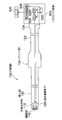
- FIG. 1 is an overall configuration diagram showing an embodiment of a medical observation system.
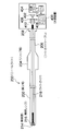
- FIG. 2 is a schematic diagram illustrating a configuration example of an endoscope.
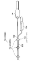
- FIG. 3 is a schematic diagram illustrating a configuration example of a needle light.
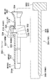
- FIG. 4 is a schematic view showing a configuration example of a trocar.
- FIG. 5 is a schematic view showing a scope unit in which an insertion portion of an endoscope and an insertion portion of a needle light are integrated by a holding device.
- FIG. 6 is a plan view illustrating a configuration example of the connection fixture.
- FIG. 7 is a schematic view showing an aspect in which the length of the insertion portion of the needle light is configured to be shorter than the length of the insertion portion of the endoscope.
- FIG. 1 is an overall configuration diagram showing an embodiment of a medical observation system.
- FIG. 2 is a schematic diagram illustrating a configuration example of an endoscope.
- FIG. 3 is a schematic diagram illustrating a configuration example of a
- FIG. 8 is a plan view showing a first modification of the connection fixture.
- FIG. 9 is a plan view showing a second modification of the connection fixture.
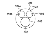
- FIG. 10 is a plan view showing a third modification of the connection fixture.
- FIG. 11 is a plan view showing a fourth modification of the connection fixture.
- FIG. 12 is a plan view showing a fifth modification of the connection fixture.
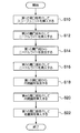
- FIG. 13 is a flowchart showing a procedure for inserting the body cavity insertion tool into the abdominal cavity.
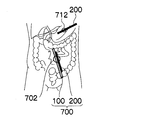
- FIG. 14A is a diagram schematically illustrating a state in which the body cavity insertion tool is inserted into the abdominal cavity.
- FIG. 14B is a diagram schematically illustrating a state where the body cavity insertion tool is inserted into the abdominal cavity.
- FIG. 14A is a diagram schematically illustrating a state in which the body cavity insertion tool is inserted into the abdominal cavity.
- FIG. 14B is a diagram schematically illustrating a state where the body cavity insertion tool is inserted into the
- FIG. 14C is a diagram schematically illustrating a state where the body cavity insertion tool is inserted into the abdominal cavity.
- FIG. 14D is a diagram schematically illustrating a state where the body cavity insertion tool is inserted into the abdominal cavity.
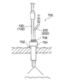
- FIG. 15 is a cross-sectional view schematically showing how the intracorporeal insertion tool is inserted into the abdominal cavity.
- FIG. 16A is an explanatory diagram showing a method for inserting a trocar.
- FIG. 16B is an explanatory view showing a trocar insertion method.
- FIG. 16C is an explanatory diagram showing a trocar insertion method.
- FIG. 1 is an overall configuration diagram showing an embodiment of a medical observation system.
- a medical observation system 10 includes an endoscope 100 for observing a portion to be observed in a body cavity, and a needle light (illumination) that irradiates illumination light into the body cavity of the subject. ) 200, a light source device 400 that supplies illumination light to the needle light 200, and a processor device 500 that generates an endoscopic image.
- the processor device 500 is connected to a monitor 600 for displaying an endoscopic image.
- FIG. 2 is a schematic diagram illustrating a configuration example of the endoscope 100.
- An endoscope (electronic endoscope) 100 shown in FIG. 2 includes a rigid insertion portion 102 to be inserted into a body cavity of a subject, a grip portion 104 provided at the rear end of the insertion portion 102, and a grip portion 104. And a signal cable 122 extending from the rear end.
- a connector 124 that is detachably connected to the processor device 500 is provided at the end of the signal cable 122.
- the observation window 110 for taking in the image light of the subject is attached to the tip of the insertion unit 102. Behind the observation window 110, an objective optical system 112 and a solid-state imaging device 120 (CMOS (Complementary Metal-Oxide Semiconductor) sensor, CCD (Charge-Coupled Device) sensor, etc.) are arranged. Subject light that has passed through the observation window 110 and the objective optical system 112 is incident on the imaging surface (light receiving surface) of the solid-state imaging device 120.
- the solid-state imaging device 120 photoelectrically converts incident subject light to convert it into an electrical signal (imaging signal) and output it.
- the electrical signal output from the solid-state imaging device 120 is input to the processor device 500 via the signal cable 122 and the connector 124.
- the processor device 500 includes a CPU 502, a DSP (Digital Signal Processor) 504, a DIP 506, and a display control circuit 508.
- the CPU 502 controls the overall operation of the processor device 500.
- the DSP 504 performs various signal processing such as color separation, color interpolation, gain correction, white balance adjustment, and gamma correction on the electrical signal output from the solid-state imaging device 120 to generate image data.
- Image data generated by the DSP 504 is input to a DIP (digital image processing circuit) 506.
- DIP digital image processing circuit
- the DIP 506 performs various types of image processing such as electronic scaling, color enhancement, and edge enhancement on the image data processed by the DSP 504. Image data that has been subjected to various types of image processing by the DIP 506 is input to the display control circuit 508.
- the display control circuit 508 converts the image data from the DIP 506 into a video signal corresponding to a signal format corresponding to the monitor 600 and outputs the video signal to the monitor 600. Thereby, an observation image (endoscopic image) is displayed on the monitor 600.
- the insertion unit 102 of the endoscope 100 does not include an illumination unit that illuminates the body cavity. That is, there is no illumination window or light guide provided in a general endoscope, and an occupied space for arranging these members is unnecessary. For this reason, the outer diameter of the insertion portion 102 can be reduced, thereby reducing the opening size of the opening (insertion hole) formed in the body wall in order to guide the insertion portion 102 into the body cavity. it can. This makes it possible to make post-operative scars inconspicuous and reduce the burden on the subject.
- the outer diameter of the insertion portion 102 is preferably 3 mm or less.
- the outer diameter of the insertion portion 102 is configured to 2.9 mm.
- the opening size of the opening (insertion hole) formed in the body wall in order to guide the insertion portion 102 into the body cavity can be reduced. This eliminates the need for suturing the opening and makes postoperative scars less noticeable.
- the outer diameter of the insertion portion 102 is made too thin, the space occupied by a built-in object (for example, an image guide) built in the insertion portion 102 is insufficient, and therefore the outer diameter of the insertion portion 102 is 2 mm or more. It is preferable.
- the endoscope 100 is configured by an electronic endoscope (electronic scope), but may be configured by an optical endoscope (fiber scope).
- FIG. 3 is a schematic diagram illustrating a configuration example of the needle light 200.
- the needle light 200 includes an insertion portion 202 that is inserted into a body cavity, a grip portion 204 that is provided at the rear end of the insertion portion 202, and a light that extends from the rear end of the grip portion 204. And a guide cable 206.
- a light source connector 208 that is detachably connected to the light source device 400 is provided at the end of the light guide cable 206.
- the insertion portion 202 is made of an elongated cylindrical member having flexibility, and an illumination window 214 is attached to the distal end surface thereof.
- an illumination lens 216 for irradiating illumination light toward the body cavity is disposed in the back of the illumination window 214.
- the illumination lens 216 faces the emission end of the light guide 218.
- the light guide 218 is inserted into the insertion portion 202, the grip portion 204, and the light guide cable 206, and its incident end is exposed from the end portion of the light source connector 208.
- the incident end of the light guide 218 is inserted into the light source device 400. Illumination light from the light source device 400 is guided to the distal end portion of the insertion portion 202 by the light guide 218 and is irradiated into the body cavity from the illumination lens 216 and the illumination window 214.
- the light source device 400 includes a light source 402, a light source driver 404, an aperture adjustment mechanism 406, an iris driver 408, and a CPU 410 that controls these units.
- the light source 402 is turned on and off under the control of the light source driver 404 and irradiates illumination light toward the condensing lens 412 positioned in front.
- a xenon lamp, a halogen lamp, an LED (light emitting diode), a fluorescent light emitting element, or an LD (laser diode) can be used.
- the light source 402 is appropriately selected depending on what endoscopic image (a visible image, a fluorescent image, or the like) is captured, that is, a wavelength to be used.
- the aperture adjustment mechanism 406 is disposed between the light source 402 and the condenser lens 412 so that the endoscopic image captured by the solid-state imaging device 120 (see FIG. 2) of the endoscope 100 has substantially constant brightness. Adjust the amount of illumination light.
- the aperture adjustment mechanism 406 includes an aperture blade that changes the diameter (diaphragm diameter) of an aperture opening through which illumination light passes, and a motor that drives the aperture blade.
- the iris driver 408 adjusts the amount of illumination light incident on the light guide 218 by changing the illumination light passage area by opening and closing the aperture blades of the aperture adjustment mechanism 406.
- the outer diameter of the insertion portion 202 is preferably 3 mm or less, and more preferably 2.5 mm or less. In this example, the outer diameter of the insertion portion 202 is 2.1 mm.
- the illumination light from the light source device 400 is guided to the distal end portion of the insertion portion 202 by the light guide 218, and is irradiated into the body cavity from the illumination lens 216 and the illumination window 214.
- the configuration of the needle light is not limited to this, and a configuration in which an LED light source is built in the tip of the needle light may be used.
- FIG. 4 is a schematic diagram illustrating a configuration example of the trocar 300.
- the trocar 300 is a guide member for guiding the needle light 200 into the body cavity, and includes an outer tube 302 and an inner needle 304.
- the inner needle 304 is inserted into the outer tube 302, and is provided on an elongated shaft portion 306, a distal end portion 308 formed at the distal end of the shaft portion 306, and a proximal end side of the shaft portion 306.
- the head 310 is formed.
- the outer diameter of the shaft portion 306 of the inner needle 304 is 2.1 mm.
- the tip 308 has a curved shape and is dull so as not to be edged (that is, a rounded non-edge shape), but can easily penetrate the body wall.
- the outer diameter of the shaft portion 306 is slightly smaller than the inner diameter of the outer tube 302.
- the head portion 310 is formed in a columnar shape that is thicker than the shaft portion 306. When the inner needle 304 is inserted into the outer tube 302, the head portion 310 has a proximal end side of the outer tube 302 with the distal end portion 308 of the inner needle 304 protruding from the distal end of the outer tube 302 by a predetermined length. It abuts on the end face.
- the outer tube 302 includes an elongated rigid portion 312 formed of a hard resin, metal, or the like, a flexible portion 314 coupled to the distal end side of the rigid portion 312, and a main body portion 316 coupled to the proximal end side of the rigid portion 312.
- the guide portion 318 is connected to the base end side of the main body portion 316, and the introduction portion 320 is provided on the base end side of the guide portion 318.
- the rigid portion 312, the flexible portion 314, the main body portion 316, the guide portion 318, and the introduction portion 320 are arranged on the same axis, and an insertion passage 322 through which the needle light 200 and the inner needle 304 can be inserted is provided inside them. Is formed.
- the outer diameter of the rigid portion 312 is 2.3 mm.
- the soft part 314 is formed of a soft member such as rubber or soft resin.
- the soft portion 314 is made of the same material as the hard portion 312 (that is, hard resin, metal, etc.), and has a slit (narrow groove) along the circumferential direction or the axial direction or other direction on the outer peripheral portion thereof.
- a plurality may be formed and may be configured to have more flexibility than the rigid portion 312.
- the tip portion 314a of the soft portion 314 is formed in a tapered shape that continuously decreases in thickness over a predetermined length, and the tip side is more flexible (flexible). Yes.
- tip part 314a becomes a rounded non-edge shape.
- the soft portion 314 disposed at the distal end portion of the outer tube 302 contacts the organ in a state where the inner needle 304 is pulled out from the outer tube 302 inserted into the body cavity, the soft portion 314 is not soft. Since it deforms itself depending on the sex, it becomes possible to prevent organ damage.
- the rigid portion 312 is a portion formed at a portion surrounded by the body wall when the outer tube 302 is inserted into the body cavity, and is formed of a hard member such as a hard resin or metal. Therefore, when the trocar 300 is sent to a predetermined position in the body cavity and the inner needle 304 is extracted from the outer tube 302, a compressive force from the body wall acts on the outer tube 302. 302 is not deformed by the pressing force, and the needle light 200 can be smoothly inserted into the outer tube 302.
- the main body 316 includes an elastic body layer 324 provided on the entire surface thereof, and an inner tube portion 326 provided on the inner side of the elastic body layer 324.
- the elastic body layer 324 is made of an elastic member such as rubber or sponge.
- the elastic layer 324 preferably functions relatively thick because it functions as a means for absorbing pressure applied to the patient. As a result, when the outer tube 302 is inserted into the body cavity, even if the main body 316 of the outer tube 302 is in contact with the body wall for a long time and pressure is applied, the pressure is absorbed by the elastic layer 324. Therefore, the burden on the patient can be reduced and minimal invasiveness can be achieved.
- the inner tube portion 326 is formed of a hard member such as hard resin or metal, like the hard portion 312.
- the inner tube portion 326 may be configured integrally with the rigid portion 312 or may be configured separately. In the latter case, the inner tube portion 326 and the hard portion 312 are connected by an adhesive or brazing.
- an internal pipe line 328 that constitutes a part of the insertion path 322 is formed.
- a check valve 330 and a seal member 332 are arranged in parallel in the axial direction in the internal conduit 328.
- the check valve 330 prevents the pressurized air in the body cavity from leaking out of the body when the needle light 200 or the inner needle 304 is removed from the outer tube 302.
- the seal member 332 is disposed on the proximal end side with respect to the check valve 330, and when the needle light 200 or the inner needle 304 is inserted into the outer tube 302, the needle light 200 or the inner needle 304 and the inner pipe line 328 are connected. It is for sealing the gap.
- the check valve 330 and the seal member 332 are made of an elastic member such as rubber, for example.
- the guide portion 318 is configured to have an inner diameter slightly larger than the outer diameter of the insertion portion 202 of the needle light 200 and to have a predetermined length in the axial direction.
- the guide portion 318 is formed of a hard member such as a hard resin or metal, like the hard portion 312 and the inner tube portion 326.
- the guide portion 318 may be configured integrally with the inner tube portion 326 or may be configured separately. In the latter case, the guide portion 318 and the inner tube portion 326 are connected by an adhesive or brazing. Needless to say, the rigid portion 312, the inner tube portion 326, and the guide portion 318 may be integrally formed.
- a conical introduction portion 320 having an inner diameter larger than that of the guide portion 318 is integrally provided on the proximal end side of the guide portion 318.
- An opening 334 for inserting the needle light 200 and the inner needle 304 into the outer tube 302 is formed on the end face on the proximal end side of the introduction part 320, and the insertion passage 322 communicates with the opening 334. It has become.
- the introduction portion 320 is formed so as to expand toward the proximal end side, and the needle light 200 and the inner needle 304 can be easily guided to the insertion passage 322 from the opening 334 of the introduction portion 320.
- the inner needle 304 is inserted into the outer tube 302, and the distal end portion 308 of the inner needle 304 is protruded from the distal end of the outer tube 302. Then, the tip of the inner needle 304 incorporated in the outer tube 302 is inserted directly from the body skin to a predetermined depth position. Thereafter, the inner needle 304 is removed from the outer tube 302. Then, by inserting the insertion portion 202 of the needle light 200 into the outer tube 302, the insertion portion 202 of the needle light 200 can be guided into the body cavity.
- the trocar is composed of a mantle tube and an inner needle, as in the trocar 300 described above, and is partially incised with a scalpel or the like, and is inserted into the body cavity from the incised portion or a special incision.
- a slight incision is made even if it is incised, and then directly inserted into the body cavity from the body epidermis, and any type can be used.
- the insertion unit 102 of the endoscope 100 does not include an illumination unit that illuminates the body cavity. Therefore, when one of the insertion portion 102 of the endoscope 100 and the insertion portion 202 of the needle light 200 is to be inserted into the body cavity prior to the other, it is confirmed that it is safely inserted into the body cavity. There is no art.
- the holding device 730 shown in FIG. 5 is used so that the insertion portion 102 of the endoscope 100 and the insertion portion 202 of the needle light 200 can be safely inserted into the body cavity.
- FIG. 5 is a schematic view showing a scope unit 700 in which the insertion portion 102 of the endoscope 100 and the insertion portion 202 of the needle light 200 are integrated by a holding device 730.
- the holding device 730 includes a plurality of connecting fixtures (holding members) 706 arranged at predetermined intervals along the longitudinal direction of the insertion portion 102 of the endoscope 100.
- the insertion part 102 of the mirror 100 and the insertion part 202 of the needle light 200 are integrated in a state of being parallel and close to each other.
- the insertion portion 102 of the endoscope 100 and the insertion portion 202 of the needle light 200 are integrated by three connection fixtures 706, but the number of connection fixtures 706 is not limited, and at least two connection fixtures 706 are provided. What is necessary is just to be integrated by the fixing tool 706.
- FIG. 6 is a plan view showing a configuration example of the connection fixture 706.
- the connection fixture 706 is formed of a thin disk-like member, and is formed of a resin material such as plastic or an elastic material such as rubber.
- the connection fixture 706 includes a first holding portion 732 that holds the insertion portion 102 of the endoscope 100 slidably along its longitudinal direction, and an insertion portion 202 of the needle light 200 that is slidable along its longitudinal direction. And a second holding portion 734 to be held.
- the first holding part 732 includes a first insertion hole 708 through which the insertion part 102 of the endoscope 100 can be inserted.
- the first insertion hole 708 has an inner diameter slightly larger than the outer diameter of the insertion portion 102, and the insertion portion 102 held by the first holding portion 732 is configured to be slidable along the longitudinal direction thereof.
- the second holding part 734 includes a second insertion hole 710 through which the insertion part 202 of the needle light 200 can be inserted.
- the second insertion hole 710 has an inner diameter slightly larger than the outer diameter of the insertion portion 202, and the insertion portion 202 held by the second holding portion 734 is configured to be slidable along its longitudinal direction.
- the inner diameters of the first and second insertion holes 708 and 710 have sizes corresponding to the outer diameters of the respective insertion portions 102 and 202, and the inner diameter of the first insertion hole 708 is the second inner diameter. It is configured to be larger than the inner diameter of the insertion hole 710.
- the insertion portions 102 and 202 are inserted into the first and second insertion holes 708 and 710 of the coupling fixtures 706, respectively. In a state, these are arranged at predetermined intervals along the longitudinal direction. Thereby, the insertion part 102 of the endoscope 100 and the insertion part 202 of the needle light 200 are integrated in a state of being parallel and close to each other.
- the scope unit 700 integrated by the holding device 730 is inserted into the body cavity via the trocar 704 as described later (see FIG. 15). Accordingly, it is possible to safely insert the insertion portion 102 of the endoscope 100 and the insertion portion 202 of the needle light 200 into the body cavity while performing illumination and observation in the body cavity.
- the length relationship between the insertion portion 102 of the endoscope 100 and the insertion portion 202 of the needle light 200 is not particularly limited, but is inserted together into the body cavity as described later.
- the insertion portion 202 of the needle light 200 is shown in FIG.
- the length is preferably configured to be shorter than the length of the insertion portion 102 of the endoscope 100. According to this aspect, the insertion portion 202 of the needle light 200 can be easily removed without interfering with the grip portion 104 provided on the proximal end side of the insertion portion 102 of the endoscope 100.
- each insertion hole 708, 710 is configured by a through hole independent from each other.
- 710 may be constituted by through holes communicating with each other.
- the insertion portion 102 of the endoscope 100 and the insertion portion 202 of the needle light 200 can be integrated as in the present embodiment.
- the holding portions 732 and 734 are provided with cutout portions 736 and 738 in which part of the peripheral walls of the insertion holes 708 and 710 are partially cutout.
- the insertion portions 102 and 202 are inserted through the notches 736 and 738, so that the insertion portions 102 and 202 are easily inserted into the insertion holes 708 and 710. Can be canceled easily.
- a configuration in which one insertion hole 706, 708 is provided in the connection fixture 706 is shown, but the present invention is not limited to this.
- the third to fifth examples shown in FIGS. As in the modification, a plurality of second insertion holes 710A and 710B may be provided. 10 to 12 correspond to FIGS. 6, 8, and 9, respectively.
- the insertion portions of the plurality of needle lights 200 with respect to the insertion portion 102 of the endoscope 100. 202 can be integrated. Thereby, when the brightness of illumination light is insufficient with only one needle light 200, a desired brightness can be ensured.
- the number of the second insertion holes 710 is not limited to two, and may be three or more.
- a plurality of first insertion holes 708 may be formed.
- connection fixture 706 is made of an elastic material such as rubber. According to this aspect, the opening formed by the notches 736 and 738 can be expanded and contracted, and the insertion portions 102 and 202 can be easily attached to and detached from the connection fixture 706.
- the medical observation system 10 of the present embodiment configured as described above is used for laparoscopic surgery, and is used for treatment in the abdominal cavity that is one of the body cavities of a patient.
- a method of placing the intra-body-cavity insertion tool (endoscope 100 and needle light 200) of the medical observation system 10 of the present embodiment in the abdominal cavity that is a patient's body cavity is illustrated in FIG. This will be described in detail below with reference to FIGS.
- FIG. 13 is a flowchart showing a procedure for inserting the intra-body-cavity insertion tool constituting the medical observation system 10 of the present embodiment into the abdominal cavity.
- 14A to 14D are diagrams schematically showing a state where the intra-body-cavity insertion tool is inserted into the abdominal cavity.
- FIG. 15 is a cross-sectional view schematically showing how the intracorporeal insertion tool is inserted into the abdominal cavity. Note that the series of steps shown in FIG. 13 is a step that takes into account minimally invasiveness in addition to safety.
- the insertion unit 102 of the endoscope 100 and the insertion unit 202 of the needle light 200 are integrated by a holding device 730 through a first opening (insertion hole) 702 formed in the abdominal wall.
- the converted scope unit 700 is inserted into the abdominal cavity (step S10 in FIG. 13).
- the first opening 702 is an opening formed in a patient's abdomen (for example, the umbilicus) in order to insert a treatment tool such as forceps into the abdominal cavity.
- a trocar 704 having a size corresponding to the outer diameter of the treatment instrument (for example, a 5 mm forceps trocar) is inserted into the first opening 702, and the scope unit 700 is inserted into the abdominal cavity through the trocar 704.
- preparation tilt arrangement
- insertion holes opening unnecessary openings
- each connecting fixture 706 does not enter the trocar 704, but abuts against the end surface on the proximal end side of the trocar 704 and is stacked. It becomes a state. Then, the insertion portion 102 of the endoscope 100 and the insertion portion 202 of the needle light 200 are guided into the body cavity by the trocar 704. Accordingly, it is possible to safely insert the insertion portion 102 of the endoscope 100 and the insertion portion 202 of the needle light 200 into the body cavity while performing illumination and observation in the body cavity.
- the other needle light 200 is intraperitoneally passed through the second opening 712 formed at a position different from the first opening 702 (for example, the upper right part of the abdomen). (Step S12 in FIG. 13).
- the trocar 300 needle light trocar shown in FIG. 4 is inserted into the second opening 712, and another needle light 200 is inserted into the abdominal cavity through the trocar 300.
- the insertion portions 202 of the two needle lights 200 are inserted into the abdominal cavity. For this reason, even if one of the needle lights 200 is extracted, the inside of the body cavity can be illuminated by the other needle light 200, and the endoscope 100 having no illumination means does not fall into an unobservable state.
- the insertion portion 202 of the needle light 200 is removed from the first opening 702 (step S14 in FIG. 13).
- the first and second openings 702 and 712 are connected to the first opening 714 formed at a position different from the first and second openings 702 and 712 (for example, the left central portion of the abdomen).
- the insertion portion 202 of the needle light 200 removed from the opening 702 is inserted into the abdominal cavity (step S16 in FIG. 13).
- the insertion portion 102 of the endoscope 100 is removed from the first opening 702 (step S18 in FIG. 13).
- 4th opening part 716 is an opening part formed in order to insert the insertion part 102 of the endoscope 100 in the abdominal cavity.
- a trocar 718 (for example, 3 mm trocar) having a size corresponding to the outer diameter of the insertion portion 102 of the endoscope 100 is inserted into the fourth opening 716, and the insertion portion 102 of the endoscope 100 is inserted through the trocar 718. Is inserted into the abdominal cavity.
- a treatment tool 720 such as a 5 mm forceps is inserted into the abdominal cavity through the first opening 702 (step S22 in FIG. 13).
- the insertion portion 102 of the endoscope 100 and the insertion portion 202 of the needle light 200 are arranged in the abdominal cavity of the patient, thereby making it possible to perform predetermined examinations and treatments.
- the insertion unit 102 of the endoscope 100 and the insertion unit 202 of the needle light 200 are integrated by the holding device 730 even if the endoscope 100 does not have illumination means.
- the scope unit 700 By inserting the scope unit 700 into a body cavity such as the abdominal cavity, the insertion part 102 of the endoscope 100 and the insertion part 202 of the needle light 200 are safely inserted into the body cavity while illuminating and observing the body cavity. It becomes possible.
- the insertion unit 102 of the endoscope 100 and the insertion unit 202 of the needle light 200 are inserted into the body cavity according to the procedure shown in FIG.
- the insertion part 102 of the endoscope 100 and the insertion part 202 of the needle light 200 can be safely arranged at a desired position while always performing illumination and observation in the body cavity.
- the second to fourth openings 712, 714, and 716 pass the insertion part 102 of the endoscope 100 and the insertion part 202 of the needle light 200 through the body cavity. It is an opening for leading inward, and the size of the opening may be smaller than that of the first opening 702. For this reason, scars after the operation are not conspicuous, the burden on the patient can be reduced, and minimal invasiveness can be achieved.
- an opening can be formed and accessed at an arbitrary position corresponding to the treatment target region, the operation is not cramped, and the treatment target region can be easily observed and treated.
- a treatment target site that cannot be directly accessed from one opening can be easily accessed, and treatment can be performed stably.
- FIGS. 16A to 16C are explanatory diagrams showing a method for inserting the trocar 300.
- FIG. 16A to 16C are explanatory diagrams showing a method for inserting the trocar 300.
- the inner needle 304 is incorporated in the outer tube 302, and the trocar 300 is along a direction (first direction) substantially perpendicular to the body skin that is the outer surface of the abdominal wall. Is inserted from the body skin to a predetermined depth in the abdominal wall. At this time, the distal end of the trocar 300 (specifically, the distal end portion 308 of the inner needle 304 protruding from the distal end of the mantle tube 302) is in the middle of the muscle layer (between the body epidermis and the peritoneum, preferably the middle position of the muscle layer). Until the peritoneum is reached.
- the trocar 300 with its tip inserted halfway through the muscle layer is tilted. That is, the trocar 300 is tilted obliquely so that the main body portion 316 of the outer tube 302 approaches the body skin, and the longitudinal axis direction of the insertion portion (hard portion 312 and soft portion 314) of the outer tube 302 is inclined with respect to the body skin. To be in the direction.
- the tip of the trocar 300 is inserted in an oblique direction (second direction) with respect to the body skin.
- the distal end of the inner needle 304 inserted into the outer tube 302 passes through the peritoneum and is inserted to a depth where the distal end of the outer tube 302 is in the abdominal cavity.
- a path for guiding the insertion portion 202 of the needle light 200 into the abdominal cavity is secured by the insertion passage 322 in the outer tube 302.
- the distal end of the insertion portion 202 of the needle light 200 can be guided into the abdominal cavity by inserting the insertion portion 202 of the needle light 200 through the insertion passage 322 of the outer tube 302.
- the distal end of the trocar 300 is placed in the abdominal wall along a direction substantially perpendicular to the body epidermis (first direction).
- first direction a direction substantially perpendicular to the body epidermis
- second direction a direction that is sharper than the first direction with respect to the body epidermis.
- Insert into the abdominal cavity in the first direction, the inclination angle (insertion angle) ⁇ 1 with respect to the body skin is preferably 70 to 110 degrees, more preferably 80 to 100 degrees, and particularly preferably 85 to 95 degrees.
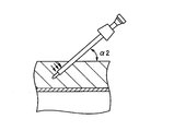
- the inclination angle (insertion angle) ⁇ 2 with respect to the body skin is preferably 60 degrees or less, more preferably 45 degrees or less, and particularly preferably 30 degrees or less.
- the rigid portion 312 (the portion formed at the portion surrounded by the body wall) of the outer tube 302 is muscular as indicated by the arrows shown in FIGS. 16B and 16C. Receive greater resistance from the layer. For this reason, compared with the case where it inserts without changing the insertion direction of the trocar 300, the trocar 300 stabbed in the abdominal cavity is fixed reliably. As a result, the needle light 200 inserted into the trocar 300 is stabilized without being affected by body movement or external vibration, and damage to the target organ and other surrounding organs can be prevented.
- the needle light 200 inserted into the trocar 300 is fixed in an obliquely stable state, it is possible to stably irradiate the treatment target site over a wider range. Further, if the needle light 200 can be fixed, the operation is not necessary, and the operation can be performed without adding the operation of the needle light 200 to the normal laparoscopic surgery, that is, without increasing the number of operators who operate the needle light 200. It becomes possible.
- the application target of the insertion method shown in FIGS. 16A to 16C is not limited to the trocar 300, and any medical device that can be directly inserted (punctured) from the patient's body skin can be applied in the same manner. .
- the endoscope of the present invention includes, for example, auxiliary illumination means capable of emitting auxiliary illumination light. It can be applied to other endoscopes. If it is an endoscope provided with the auxiliary illumination means, a diameter can be reduced compared with the conventional general endoscope, and the effect of this invention can fully be exhibited.
Landscapes
- Health & Medical Sciences (AREA)
- Life Sciences & Earth Sciences (AREA)
- Surgery (AREA)
- Nuclear Medicine, Radiotherapy & Molecular Imaging (AREA)
- Biomedical Technology (AREA)
- Optics & Photonics (AREA)
- Pathology (AREA)
- Radiology & Medical Imaging (AREA)
- Biophysics (AREA)
- Engineering & Computer Science (AREA)
- Physics & Mathematics (AREA)
- Heart & Thoracic Surgery (AREA)
- Medical Informatics (AREA)
- Molecular Biology (AREA)
- Animal Behavior & Ethology (AREA)
- General Health & Medical Sciences (AREA)
- Public Health (AREA)
- Veterinary Medicine (AREA)
- Endoscopes (AREA)
Description
本発明は、保持装置及び医療用観察システムに係り、特に、体腔内に内視鏡及び照明具を安全に挿入する技術に関する。
近年、開腹、開胸等を行う外科手術に比べて患者への侵襲が小さいことから、腹腔鏡等の硬性内視鏡(硬性鏡)を用いた内視鏡下外科手術が広く行われている。例えば、腹腔鏡下外科手術では、患者の腹部の数箇所に筒状のトラカールを刺入し、このトラカールを通じて内視鏡(腹腔鏡)や処置具等を腹腔内に挿入して、モニタで内視鏡画像を観察しながら処置具を使って処置を行う。
また、最近では、臍部に1つの孔をあけて腹腔鏡下外科手術を行う単孔式腹腔鏡下手術(Single Port Surgery:SPS)が急速に普及しつつある。この単孔式腹腔鏡下手術では、術後の傷痕は臍部の1箇所のみとなるので目立ちにくく、美容的に優れている。
しかしながら、単孔式腹腔鏡下手術では、体腔内へアクセスするために体壁に形成される開口部(挿通孔)が1箇所のみであるため、体腔内外で内視鏡や処置具が干渉しやすく、操作が窮屈になりやすい。また、内視鏡と処置具が干渉すると、内視鏡が観察に都合のよい位置取りをできない場合が生じ、処置対象部位の観察及び処置に支障をきたすことになる。
このような背景のもと、内視鏡の挿入部の細径化の要求が高まっている。内視鏡の挿入部の細径化を図ることができれば、臍部以外の部分に内視鏡用の開口部を形成しても、その開口サイズが小さくなり、術後の傷痕を目立たなくすることができる。また、1つの開口部から体腔内へアクセスする場合に比べて操作面や観察面での不具合も解消することができる。
ここで、一般に内視鏡は、体腔内を観察するための機能とともに体腔内を照明するための機能を備えている。すなわち、内視鏡の挿入部には、光源装置からの照明光を伝達するためのライトガイドが挿通配置されており、その出射端から出射された照明光は照明窓を介して体腔内に照射されるようになっている。このため、内視鏡の挿入部を細くしすぎると、ライトガイドを挿通配置するための占有スペースが不足し、照明光の明るさ不足が発生する。
これに対し、特許文献1には、体腔内を観察するための内視鏡と、内視鏡とは別体に構成され、体腔内を照明するための照明具(照明用プローブ)とを備えたシステムが開示されている。このシステムによれば、内視鏡から照射される照明光の明るさ不足が生じる場合でも、照明具から照射される照明光により所望の明るさを確保することが可能となる。また、観察位置に様々な方向から照明光を照射することができるので、観察位置がより一層観察しやすくなる。
しかしながら、特許文献1に開示されるシステムにおいて、内視鏡の挿入部を細くしすぎると、上述のように照明光の明るさ不足が生じる。このため、照明具が体腔内に導かれる前に内視鏡を体腔内に挿入しようとすると、照明光の明るさ不足により、体腔内の様子をモニタで観察することは困難となる。したがって、内視鏡を体腔内の所望の位置に安全に配置するのは難しい問題がある。
一方、体腔内に内視鏡よりも先に照明具を配置しておくことも考えられるが、照明具は体腔内を観察するための機能を具備しておらず、体腔内の様子をモニタで観察しながら照明具を体腔内に挿入することはできない。このため、照明具の先端が臓器に接触してしまい、臓器損傷を引き起こしてしまう恐れがある。
特に、内視鏡から体腔内を照明するための機能を省いた場合には、ライトガイドの占有スペースが不要となるため、内視鏡の挿入部の細径化を図ることができる反面、内視鏡と照明具とのいずれか一方を他方に先立って体腔内に挿入しようとすると、安全に体腔内に挿入されていることを確認する術がなく、上記問題はより深刻なものとなる。
本発明は、このような事情に鑑みてなされたもので、体腔内に内視鏡及び照明具を安全に挿入することができる保持装置及び医療用観察システムを提供することを目的とする。
前記目的を達成するために、本発明の一態様に係わる保持装置は、体腔内に挿入され体腔内を観察可能な観察手段が設けられた挿入部を有する内視鏡と、内視鏡とは別体に構成され、体腔内に挿入され体腔内を照明可能な照明手段が設けられた照明具とを一体的に保持する保持装置であって、内視鏡の挿入部をその長手方向に沿ってスライド自在に保持する第1の保持部と、照明具の挿入部をその長手方向に沿ってスライド自在に保持する第2の保持部とを有する保持部材を複数備え、各保持部材は、内視鏡の挿入部の長手方向に沿って所定の間隔をあけて配置され、内視鏡及び照明具の挿入部同士を互いに平行かつ近接した状態で保持する。
この保持装置において、第1及び第2の保持部は、保持部材に形成された第1及び第2の挿通孔を有する態様が好ましい。また、好ましい態様として、第1及び第2の挿通孔は、互いに独立した貫通孔により構成される。また、別の好ましい態様として、第1及び第2の挿通孔は、互いに連通した貫通孔により構成される。これらの態様において、第1及び第2の保持部は、第1及び第2の挿通孔の周壁が部分的に切り欠かれた第1及び第2の切欠き部を有することが好ましい。
また、この保持装置において、内視鏡は、体腔内を照明するための照明手段を備えていない態様が好ましい。
また、前記目的を達成するために、本発明の別の一態様に係わる医療用観察システムは、体腔内に挿入され体腔内を観察可能な観察手段が設けられた挿入部を有する内視鏡と、内視鏡とは別体に構成され、体腔内に挿入され体腔内を照明可能な照明手段が設けられた挿入部を有する照明具と、内視鏡の挿入部をその長手方向に沿ってスライド自在に保持する第1の保持部と、照明具の挿入部をその長手方向に沿ってスライド自在に保持する第2の保持部とを有する保持部材を複数有し、各保持部材は、内視鏡の挿入部の長手方向に沿って所定の間隔をあけて配置され、内視鏡及び照明具の挿入部同士を互いに平行かつ近接した状態で保持する保持装置と、を備える。
この医療用観察システムにおいて、第1及び第2の保持部は、保持部材に形成された第1及び第2の挿通孔を有する態様が好ましい。また、好ましい態様として、第1及び第2の挿通孔は、互いに独立した貫通孔により構成される。また、別の好ましい態様として、第1及び第2の挿通孔は、互いに連通した貫通孔により構成される。これらの態様において、第1及び第2の保持部は、第1及び第2の挿通孔の周壁が部分的に切り欠かれた第1及び第2の切欠き部を有することが好ましい。
また、この医療用観察システムにおいて、内視鏡は、体腔内を照明するための照明手段を備えていない態様が好ましい。
また、この医療用観察システムにおいて、照明具の挿入部の長さは、内視鏡の挿入部の長さよりも短い態様が好ましい。
本発明によれば、複数の保持部材によって内視鏡及び照明具の挿入部同士を一体化させた状態で体腔内に挿入することが可能となる。これにより、体腔内の照明及び観察を行いながら、体腔内に内視鏡及び照明具を安全に挿入することができる。
以下、添付図面に従って本発明の好ましい実施の形態について詳説する。
[医療用観察システム]
図1は、医療用観察システムの一実施形態を示した全体構成図である。図1に示すように、本実施形態の医療用観察システム10は、体腔内の被観察部を観察するための内視鏡100と、被検体の体腔内に照明光を照射するニードルライト(照明具)200と、ニードルライト200に照明光を供給する光源装置400と、内視鏡画像を生成するプロセッサ装置500とから構成されている。また、プロセッサ装置500には、内視鏡画像を表示するためのモニタ600が接続されている。
図1は、医療用観察システムの一実施形態を示した全体構成図である。図1に示すように、本実施形態の医療用観察システム10は、体腔内の被観察部を観察するための内視鏡100と、被検体の体腔内に照明光を照射するニードルライト(照明具)200と、ニードルライト200に照明光を供給する光源装置400と、内視鏡画像を生成するプロセッサ装置500とから構成されている。また、プロセッサ装置500には、内視鏡画像を表示するためのモニタ600が接続されている。
[内視鏡]
図2は、内視鏡100の構成例を示した概略図である。図2に示す内視鏡(電子内視鏡)100は、被検体の体腔内に挿入される硬性の挿入部102と、挿入部102の後端に設けられたグリップ部104と、グリップ部104の後端から延設される信号ケーブル122とを備える。信号ケーブル122の端部には、プロセッサ装置500に着脱自在に接続されるコネクタ124が設けられている。
図2は、内視鏡100の構成例を示した概略図である。図2に示す内視鏡(電子内視鏡)100は、被検体の体腔内に挿入される硬性の挿入部102と、挿入部102の後端に設けられたグリップ部104と、グリップ部104の後端から延設される信号ケーブル122とを備える。信号ケーブル122の端部には、プロセッサ装置500に着脱自在に接続されるコネクタ124が設けられている。
挿入部102の先端には、被写体の像光を取り入れるための観察窓110が取り付けられている。観察窓の110の奥には、対物光学系112や固体撮像素子120(CMOS(Complementary Metal-Oxide Semiconductor)センサ、CCD(Charge-Coupled Device)センサ等)が配置される。観察窓の110及び対物光学系112を経由した被写体光は、固体撮像素子120の撮像面(受光面)に入射される。固体撮像素子120は、入射した被写体光を光電変換して電気信号(撮像信号)に変換して出力する。固体撮像素子120から出力された電気信号は、信号ケーブル122及びコネクタ124を介してプロセッサ装置500に入力される。
図2に示すように、プロセッサ装置500は、CPU502と、DSP(Digital Signal Processor)504と、DIP506と、表示制御回路508とを備えている。CPU502は、プロセッサ装置500全体の動作を統括的に制御する。
DSP504は、固体撮像素子120から出力された電気信号に対して、色分離、色補間、ゲイン補正、ホワイトバランス調整、ガンマ補正等の各種信号処理を施し、画像データを生成する。DSP504で生成された画像データは、DIP(デジタル画像処理回路)506に入力される。
DIP506は、DSP504で処理された画像データに対して、電子変倍、あるいは色強調、エッジ強調等の各種画像処理を施す。DIP506で各種画像処理を施された画像データは、表示制御回路508に入力される。
表示制御回路508は、DIP506からの画像データを、モニタ600に対応した信号形式に応じた映像信号に変換してモニタ600に出力する。これにより、モニタ600に観察画像(内視鏡画像)が表示される。
本実施形態では、内視鏡100の挿入部102は体腔内を照明する照明手段を備えていない。すなわち、一般的な内視鏡が備えている照明窓やライトガイドがなく、これらの部材を配置するための占有スペースが不要となっている。このため、挿入部102の外径を細径化することができ、それにより挿入部102を体腔内に導くために体壁に形成される開口部(挿通孔)の開口サイズを小さくすることができる。これによって、術後の傷痕を目立たなくすることが可能となり、被検体への負担を軽減することができる。
本実施形態において、挿入部102の外径は3mm以下であることが好ましい。本例では、挿入部102の外径は2.9mmに構成される。挿入部102の外径を3mm以下とすることにより、挿入部102を体腔内に導くために体壁に形成される開口部(挿通孔)の開口サイズを小さくすることができる。これによって、開口部の縫合が不要となり、術後の傷痕を目立たなくすることができる。なお、挿入部102の外径を細くしすぎてしまうと、その内部に内蔵される内蔵物(例えばイメージガイドなど)の占有スペースが不足することから、挿入部102の外径は2mm以上であることが好ましい。
なお、本実施形態では、内視鏡100は電子内視鏡(電子スコープ)により構成されるが、光学内視鏡(ファイバスコープ)により構成されていてもよい。
[ニードルライト]
図3は、ニードルライト200の構成例を示した概略図である。図3に示すように、ニードルライト200は、体腔内に挿入される挿入部202と、挿入部202の後端に設けられたグリップ部204と、グリップ部204の後端から延設されるライトガイドケーブル206とを備える。ライトガイドケーブル206の端部には、光源装置400に着脱自在に接続される光源用コネクタ208が設けられている。
図3は、ニードルライト200の構成例を示した概略図である。図3に示すように、ニードルライト200は、体腔内に挿入される挿入部202と、挿入部202の後端に設けられたグリップ部204と、グリップ部204の後端から延設されるライトガイドケーブル206とを備える。ライトガイドケーブル206の端部には、光源装置400に着脱自在に接続される光源用コネクタ208が設けられている。
挿入部202は、可撓性を有する細長の筒状部材からなり、その先端面には照明窓214が取り付けられている。照明窓214の奥には、体腔内に向けて照明光を照射する照明レンズ216が配置される。照明レンズ216は、ライトガイド218の出射端に面している。このライトガイド218は、挿入部202、グリップ部204、及びライトガイドケーブル206の内部に挿通され、その入射端が光源用コネクタ208の端部から露呈している。光源用コネクタ208を光源装置400に接続すると、ライトガイド218の入射端は光源装置400の内部に挿入される。光源装置400からの照明光は、このライトガイド218によって挿入部202の先端部まで導光され、照明レンズ216及び照明窓214から体腔内に照射される。
図3に示すように、光源装置400は、光源402と、光源ドライバ404と、絞り調節機構406と、アイリスドライバ408と、これら各部を制御するCPU410とを備えている。光源402は、光源ドライバ404の制御によって点消灯し、前方に位置する集光レンズ412に向けて照明光を照射する。光源402としては、例えばキセノンランプ、ハロゲンランプ、LED(発光ダイオード)、蛍光発光素子、あるいはLD(レーザーダイオード)等を用いることができる。光源402は、どのような内視鏡画像(可視画像や蛍光画像等)を撮像するのか、つまり使用する波長によって適宜選択される。
絞り調節機構406は、光源402と集光レンズ412の間に配置され、内視鏡100の固体撮像素子120(図2参照)によって撮像される内視鏡画像が略一定の明るさとなるように、照明光の光量を調節する。絞り調節機構406は、照明光が通過する絞り開口の直径(絞り径)を変化させる絞り羽根と、この絞り羽根を駆動するモータを備えている。アイリスドライバ408は、絞り調節機構406の絞り羽根を開閉することにより、照明光の通過面積を変化させて、ライトガイド218に入射する照明光の光量を調節する。
本実施形態において、挿入部202の外径は3mm以下であることが好ましく、2.5mm以下であることがより好ましい。本例では、挿入部202の外径は2.1mmである。これによって、内視鏡100の挿入部102と同様に、体腔内に導くために体壁に形成される開口部(挿通孔)の開口サイズを小さくすることができ、それによって術後の傷痕を目立たなくすることができる。
また、本実施形態においては、ニードルライト200として、光源装置400からの照明光をライトガイド218によって挿入部202の先端部まで導光し、照明レンズ216及び照明窓214から体腔内に照射される構成を示したが、ニードルライトの構成としてはこれに限らず、ニードルライトの先端にLED光源が内蔵された構成でもよい。
[トラカール]
図4は、トラカール300の構成例を示した概略図である。図4に示すように、トラカール300は、ニードルライト200を体腔内に導くためのガイド部材であり、外套管302と内針304とを備える。
図4は、トラカール300の構成例を示した概略図である。図4に示すように、トラカール300は、ニードルライト200を体腔内に導くためのガイド部材であり、外套管302と内針304とを備える。
内針304は、外套管302内に挿入されるものであり、細長に形成された軸部306と、軸部306の先端に形成された先端部308と、軸部306の基端側に設けられた頭部310とから構成される。なお、本例では、内針304の軸部306の外径は2.1mmとなっている。
先端部308は、曲面形状にしてエッジができないように鈍い構成(すなわち、丸みを帯びた非エッジ形状)となっているが、体壁を容易に貫通可能となっている。軸部306は、その外径が外套管302の内径より僅かに小さくなっている。頭部310は、軸部306よりも太い円柱状に形成されている。この頭部310は、外套管302内に内針304が挿入されたとき、内針304の先端部308が外套管302の先端から所定の長さだけ突出した状態で外套管302の基端側端面に当接される。
外套管302は、硬質樹脂や金属等により形成される細長い硬性部312と、硬性部312の先端側に連結された軟性部314と、硬性部312の基端側に連結された本体部316と、本体部316の基端側に連結されたガイド部318と、ガイド部318の基端側に設けられた導入部320とから構成される。硬性部312、軟性部314、本体部316、ガイド部318、及び導入部320は同軸上に配置されており、これらの内部には、ニードルライト200や内針304を挿通可能な挿通路322が形成されている。なお、本例では、硬性部312の外径は2.3mmとなっている。
軟性部314は、ゴムや軟性樹脂などの軟性部材により形成されている。また、軟性部314は、硬性部312と同様の材質(すなわち、硬質樹脂や金属等)からなり、その外周部には周方向又は軸方向、或いはその他の方向に沿ってスリット(細溝)が複数形成され、硬性部312よりも柔軟性を有するように構成されていてもよい。また、軟性部314の先端部314aは、所定の長さにわたって連続的に肉厚が薄くなるテーパ状に形成され、先端側の方がより柔軟性(可撓性)が高くなる構成となっている。しかも、その先端部314aの角部は、丸みを帯びた非エッジ形状となっている。したがって、体腔内に刺し込まれた外套管302から内針304が引き抜かれた状態において、外套管302の先端部分に配置される軟性部314が臓器に接触しても、軟性部314はその柔軟性により自ら変形するので、臓器損傷を防止することが可能となる。
硬性部312は、外套管302を体腔内に刺し込んだとき、体壁により囲繞される部位に形成される部分であり、硬質樹脂や金属などの硬性部材により形成されている。したがって、トラカール300が体腔内の所定の位置まで送り込まれて、内針304を外套管302から抜き取ると、外套管302には体壁からの圧迫力が作用するが、硬性部312により、外套管302は圧迫力で変形することがなく、ニードルライト200の外套管302への挿入を円滑に行うことが可能となっている。
本体部316は、その表面全体を設けられた弾性体層324と、弾性体層324の内側に設けられた内管部326とから構成される。
弾性体層324は、例えばゴムやスポンジなどの弾性部材により構成されている。この弾性体層324は、患者にかかる圧力を吸収する手段として機能することから比較的厚く構成されていることが好ましい。これにより、外套管302が体腔内に刺し込まれたとき、外套管302の本体部316が体壁に長時間接触して圧力がかかる状態となっても、その圧力は弾性体層324により吸収されて緩和されるので、患者への負担を少なくすることができ、低侵襲化を図ることが可能となる。
内管部326は、硬性部312と同様に、硬質樹脂や金属などの硬性部材により形成されている。内管部326は、硬性部312と一体的に構成されていてもよいし、別体に構成されていてもよい。後者の場合、接着剤やろう付けなどで内管部326と硬性部312が連結される。
内管部326には、挿通路322の一部を構成する内部管路328が形成されている。この内部管路328には、逆止弁330及びシール部材332が軸方向に並設されている。逆止弁330は、外套管302からニードルライト200あるいは内針304が抜去された状態において、体腔内の加圧空気が体外に漏れ出すことを防止するものである。シール部材332は、逆止弁330よりも基端側に配設され、外套管302にニードルライト200や内針304が挿入されたとき、ニードルライト200又は内針304と内部管路328との隙間をシールするためのものである。逆止弁330及びシール部材332は、例えばゴムなどの弾性部材により構成される。
ガイド部318は、ニードルライト200の挿入部202の外径よりも僅かに大きな内径を有し、かつ、軸方向に所定の長さを有して構成される。これにより、外套管302に挿入部202を挿入する際、挿入部202の先端部が逆止弁330やシール部材332を通過するときに大きな抵抗を受けても、その先端部が座屈変形することなく、挿入部202を先端側に向かって容易に押し込むことが可能となる。
ガイド部318は、硬性部312や内管部326と同様に、硬質樹脂や金属などの硬性部材により形成されている。ガイド部318は、内管部326と一体的に構成されていてもよいし、別体に構成されていてもよい。後者の場合、接着剤やろう付けなどでガイド部318と内管部326が連結される。また、硬性部312、内管部326、及びガイド部318が一体的に構成されてもよいことはいうまでもない。
ガイド部318の基端側には、ガイド部318よりも大きな内径を有する円錐状の導入部320が一体的に設けられている。導入部320の基端側の端面には、ニードルライト200や内針304を外套管302内に挿入するための開口部334が形成されており、その開口部334に挿通路322が連通した構成となっている。導入部320は、基端側に向かって広がるように形成されており、導入部320の開口部334からニードルライト200や内針304を挿通路322に容易に導くことが可能となっている。
以上のとおり構成されるトラカール300の使用方法としては、まず、外套管302に内針304を挿入して、この内針304の先端部308を外套管302の先端から突出させた状態にする。そして、外套管302に組み込まれた内針304の先端を体表皮から直接所定の深さ位置まで刺し込む。その後、外套管302から内針304を抜き取る。そして、ニードルライト200の挿入部202を外套管302に挿入することにより、ニードルライト200の挿入部202を体腔内に導くことができる。
なお、本実施形態において、内視鏡100や処置具720を体腔内に導くためのガイド部材であるトラカール718、704(図1参照)としては公知のものが使用されるため、その構成については説明を省略する。なお、一般にトラカールには、上述したトラカール300と同様に、外套管と内針からなり、メス等により部分的に切開して、この切開された部位から体腔内に刺し込むタイプや、格別の切開は行わず、また切開するにしろ極僅かな切開を行った上で、直接体表皮から体腔内に刺し込むタイプのものがあり、いずれのタイプのものを用いることができる。
[保持装置]
本実施形態では、上述のとおり、内視鏡100の挿入部102は体腔内を照明する照明手段を備えていない。このため、内視鏡100の挿入部102とニードルライト200の挿入部202とのいずれか一方を他方に先立って体腔内に挿入しようとすると、安全に体腔内に挿入されていることを確認する術がない。
本実施形態では、上述のとおり、内視鏡100の挿入部102は体腔内を照明する照明手段を備えていない。このため、内視鏡100の挿入部102とニードルライト200の挿入部202とのいずれか一方を他方に先立って体腔内に挿入しようとすると、安全に体腔内に挿入されていることを確認する術がない。
そこで、本実施形態では、内視鏡100の挿入部102とニードルライト200の挿入部202を体腔内に安全に挿入できるようにするために、図5に示す保持装置730が用いられる。
図5は、内視鏡100の挿入部102とニードルライト200の挿入部202が保持装置730によって一体化されたスコープユニット700を示した概略図である。
図5に示すように、保持装置730は、内視鏡100の挿入部102の長手方向に沿って所定の間隔をあけて配置された複数の連結固定具(保持部材)706からなり、内視鏡100の挿入部102とニードルライト200の挿入部202を互いに平行かつ近接した状態で一体化するものである。本例では、3つの連結固定具706によって内視鏡100の挿入部102とニードルライト200の挿入部202が一体化されているが、連結固定具706の個数に限定はなく、少なくとも2つの連結固定具706によって一体化されていればよい。
図6は、連結固定具706の構成例を示した平面図である。図6に示すように、連結固定具706は薄板の円盤状部材からなり、例えばプラスチックなどの樹脂材料、又はゴムなどの弾性材料により構成される。
連結固定具706は、内視鏡100の挿入部102をその長手方向に沿ってスライド自在に保持する第1の保持部732と、ニードルライト200の挿入部202をその長手方向に沿ってスライド自在に保持する第2の保持部734とを備える。
第1の保持部732は、内視鏡100の挿入部102を挿通可能な第1の挿通孔708を備える。第1の挿通孔708は、挿入部102の外径よりも若干大きな内径を有し、第1の保持部732によって保持された挿入部102はその長手方向に沿ってスライド自在に構成される。
第2の保持部734は、ニードルライト200の挿入部202を挿通可能な第2の挿通孔710を備える。第2の挿通孔710は、挿入部202の外径よりも若干大きな内径を有し、第2の保持部734によって保持された挿入部202はその長手方向に沿ってスライド自在に構成される。
このように第1及び第2の挿通孔708、710の内径は、各挿入部102、202の外径に応じた大きさを有しており、第1の挿通孔708の内径は第2の挿通孔710の内径よりも大きく構成される。
以上のとおり構成される保持装置730の使用方法としては、図5に示したように、各連結固定具706の第1及び第2の挿通孔708、710にそれぞれ挿入部102、202を挿通した状態にして、これらを長手方向に沿って所定の間隔をあけて配設する。これにより、内視鏡100の挿入部102とニードルライト200の挿入部202は互いに平行かつ近接した状態で一体化された状態となる。そして、保持装置730によって一体化されたスコープユニット700は、後述するようにトラカール704を介して体腔内に挿入される(図15参照)。これによって、体腔内の照明及び観察を行いながら、内視鏡100の挿入部102及びニードルライト200の挿入部202を体腔内に安全に挿入することが可能となる。
なお、本実施形態において、内視鏡100の挿入部102とニードルライト200の挿入部202との長さ関係については特に限定されるものではないが、後述するように、体腔内に一緒に挿入された内視鏡100の挿入部102及びニードルライト200の挿入部202からニードルライト200の挿入部202のみを抜去することを考慮すると、図7に示すように、ニードルライト200の挿入部202の長さは、内視鏡100の挿入部102の長さよりも短く構成されていることが好ましい。この態様によれば、内視鏡100の挿入部102の基端側に設けられるグリップ部104と干渉することなく、ニードルライト200の挿入部202を容易に抜去することが可能となる。
なお、本実施形態では、各挿通孔708、710は互いに独立した貫通孔により構成されているが、これに限らず、例えば、図8に示す第1の変形例のように、各挿通孔708、710は互いに連通した貫通孔により構成されていてもよい。第1の変形例においても、本実施形態と同様に、内視鏡100の挿入部102とニードルライト200の挿入部202を一体化させることが可能である。
また、図9に示す第2の変形例では、各保持部732、734には、各挿通孔708、710の周壁の一部が部分的に切り欠かれた切欠き部736、738が設けられる。第2の変形例によれば、各切欠き部736、738を通じて各挿入部102、202を差し込むことにより、各挿通孔708、710に各挿入部102、202を挿通させた状態に簡単にすることができるとともに、その状態を簡単に解除することもできる。
また、本実施形態では、連結固定具706に挿通孔706、708が1個ずつ設けられた構成を示したが、これに限らず、例えば、図10~図12に示す第3~第5の変形例のように、複数の第2の挿通孔710A、710Bが設けられていてもよい。なお、図10~図12は、それぞれ図6、図8、図9に対応するものである。このように複数の第2の挿通孔710A、710Bを備えた態様(第3~第5の変形例)によれば、内視鏡100の挿入部102に対し、複数のニードルライト200の挿入部202を一体化することが可能となる。これにより、1つのニードルライト200だけでは照明光の明るさ不足が生じる場合に、所望の明るさを確保することが可能となる。なお、第2の挿通孔710の個数は2つに限らず、3つ以上でもよい。また、第1の挿通孔708が複数形成されていてもよい。
なお、第2及び第5の変形例では、切欠き部736、738を通じて各挿入部102、202が差し込まれることから、連結固定具706はゴムなどの弾性材料により構成される態様が好ましい。この態様によれば、各切欠き部736、738によって形成される開口が拡縮自在となり、連結固定具706に対して各挿入部102、202を容易に着脱することが可能となる。
[体腔内挿入具の配置方法]
以上のように構成された本実施形態の医療用観察システム10は、腹腔鏡下外科手術に用いられ、患者の体腔の1つである腹腔内の治療に用いられる。ここで、腹腔鏡下外科手術のため、本実施形態の医療用観察システム10の体腔内挿入具(内視鏡100及びニードルライト200)を患者の体腔である腹腔内に配置する方法について、図13~図15を用いて、以下に詳しく説明する。
以上のように構成された本実施形態の医療用観察システム10は、腹腔鏡下外科手術に用いられ、患者の体腔の1つである腹腔内の治療に用いられる。ここで、腹腔鏡下外科手術のため、本実施形態の医療用観察システム10の体腔内挿入具(内視鏡100及びニードルライト200)を患者の体腔である腹腔内に配置する方法について、図13~図15を用いて、以下に詳しく説明する。
図13は、本実施形態の医療用観察システム10を構成する体腔内挿入具を腹腔内に挿入する手順を示したフローチャート図である。図14Aから14Dは、腹腔内に体腔内挿入具が挿入される様子を概略的に示した図である。図15は、腹腔内に体内挿入具が挿入される様子を概略的に示した断面図である。なお、図13に示した一連のステップは、安全性以外に低侵襲も考慮にいれたステップである。
まず、図14Aに示すように、腹壁に形成された第1の開口部(挿通孔)702を介して、内視鏡100の挿入部102とニードルライト200の挿入部202を保持装置730により一体化したスコープユニット700を腹腔内に挿入する(図13のステップS10)。
第1の開口部702は、腹腔内に鉗子等の処置具を挿入するために患者の腹部(例えば臍部)に形成される開口部である。第1の開口部702には処置具の外径に応じた大きさのトラカール704(例えば5mm鉗子用トラカール)が挿通され、このトラカール704を介してスコープユニット700が腹腔内に挿入される。
なお、通常の腹腔鏡下外科手術では、最低1本の5mm鉗子が必要となる。図5のステップS10は、その5mm鉗子用トラカールを活用した手技ステップであり、5mm鉗子用トラカールに2.9mmのスコープと2.1mmのニードルライト(2.9+2.1=5mm)を一緒に挿入することにより、腹壁に不必要な開口部(挿通孔)を空けることなく低侵襲で処置までの準備(トラカール配置)が可能となる。
そして、スコープユニット700がトラカール704内に挿入されると、図15に示すように、各連結固定具706はトラカール704内に入り込むことなく、トラカール704の基端側の端面に当接して積み重なった状態となる。そして、トラカール704により内視鏡100の挿入部102とニードルライト200の挿入部202が平行になった状態で体腔内に導かれる。これによって、体腔内の照明及び観察を行いながら、内視鏡100の挿入部102及びニードルライト200の挿入部202を体腔内に安全に挿入することが可能となる。
次に、図14Bに示すように、第1の開口部702とは異なる位置(例えば腹部の右上方部)に形成された第2の開口部712を介して、他のニードルライト200を腹腔内に挿入する(図13のステップS12)。
ここで、第2の開口部712には、図4に示したトラカール300(ニードルライト用トラカール)が挿通され、トラカール300を介して他のニードルライト200が腹腔内に挿入される。なお、後述する第3の開口部714についても同様である。
これにより、腹腔内には2つのニードルライト200の挿入部202が挿入された状態となる。このため、いずれか一方のニードルライト200を抜き取っても、他方のニードルライト200で体腔内を照明可能であり、照明手段をもたない内視鏡100が観察不能な状態に陥ることがない。
次に、図14Cに示すように、第1の開口部702からニードルライト200の挿入部202を抜去する(図13のステップS14)。
次に、図14Cに示すように、第1及び第2の開口部702、712とは異なる位置(例えば腹部の左中央部)に形成された第3の開口部714を介して、第1の開口部702から抜去したニードルライト200の挿入部202を腹腔内に挿入する(図13のステップS16)。
次に、第1の開口部702から内視鏡100の挿入部102を抜去する(図13のステップS18)。
次に、図14Dに示すように、第1~第3の開口部702、712、714とは異なる位置(例えば腹部の右中央部)に形成された第4の開口部716を介して、内視鏡100の挿入部102を挿入する(図13のステップS20)。
第4の開口部716は、腹腔内に内視鏡100の挿入部102を挿入するために形成される開口部である。第4の開口部716には内視鏡100の挿入部102の外径に応じた大きさのトラカール718(例えば3mmトラカール)が挿通され、このトラカール718を介して内視鏡100の挿入部102が腹腔内に挿入される。
次に、図14Dに示すように、第1の開口部702を介して5mm鉗子等の処置具720を腹腔内に挿入する(図13のステップS22)。
このようにして患者の腹腔内に内視鏡100の挿入部102やニードルライト200の挿入部202が配置されることにより、所定の検査や治療等を行うことが可能となる。
以上のように、本実施形態によれば、内視鏡100が照明手段をもたなくても、保持装置730によって内視鏡100の挿入部102とニードルライト200の挿入部202が一体化されたスコープユニット700を腹腔等の体腔内に挿入することにより、体腔内の照明及び観察を行いながら、内視鏡100の挿入部102及びニードルライト200の挿入部202を体腔内に安全に挿入することが可能となる。
また、本実施形態では、スコープユニット700を体腔内に挿入した後、図13に示した手順に従って内視鏡100の挿入部102とニードルライト200の挿入部202を体腔内に挿入することにより、体腔内の照明及び観察を常時行いながら、内視鏡100の挿入部102やニードルライト200の挿入部202を所望の位置に安全に配置することが可能となる。また、体壁に形成される開口部の数が多くなっても、第2~第4の開口部712、714、716は内視鏡100の挿入部102やニードルライト200の挿入部202を体腔内に導くための開口部であり、その開口サイズは第1の開口部702よりも小さくてすむ。このため、術後の傷痕は目立たず、患者の負担を低減することができ、低侵襲化を図ることが可能となる。
また、処置対象部位に応じた任意の位置に開口部を形成してアクセスすることができるので、操作が窮屈になることがなく、処置対象部位の観察及び処置が行いやすくなる。また、1つの開口部からでは直接アクセスすることができない処置対象部位でも容易にアクセスでき、安定して処置を行うことができる。
ここで、本実施形態におけるトラカール300の挿入方法について図16Aから16Cを参照して説明する。図16Aから16Cは、トラカール300の挿入方法を示した説明図である。
まず、図16Aに示すように、外套管302に内針304を組み込んだ状態にして、腹壁の外表面である体表皮に対して略垂直な方向(第1の方向)に沿って、トラカール300の先端を体表皮から腹壁内の所定の深さ位置まで挿入する。このとき、トラカール300の先端(具体的には、外套管302の先端から突出した内針304の先端部308)が筋層の途中位置(体表皮と腹膜の間、好ましくは筋層の中間位置から腹膜の間)に到達するまで挿入する。
次に、図16Bに示すように、筋層途中まで先端が挿入されたトラカール300を傾倒させる。すなわち、外套管302の本体部316が体表皮に近づくようにトラカール300を斜めに倒し、外套管302の挿入部(硬性部312及び軟性部314)の長手軸方向が体表皮に対して斜めの方向となるようにする。
次に、図16Cに示すように、トラカール300を傾倒させた状態のまま、トラカール300の先端を体表皮に対して斜め方向(第2の方向)に挿入する。これにより、外套管302内に挿通された内針304の先端は腹膜を通過し、外套管302の先端が腹腔内となる深さ位置まで挿入される。その後、外套管302から内針304を抜き取ることにより、外套管302内の挿通路322によりニードルライト200の挿入部202を腹腔内に導くための経路が確保される。そして、ニードルライト200の挿入部202を外套管302の挿通路322に挿通させることにより、ニードルライト200の挿入部202の先端を腹腔内に導くことができる。
図16Aから16Cに示した挿入方法によれば、トラカール300を腹腔内に刺し込む際、体表皮に対して略垂直な方向(第1の方向)に沿って、トラカール300の先端を腹壁内の途中位置(筋層途中)まで挿入した後、体表皮に対して第1の方向よりも鋭角な方向(第2の方向)に沿ってトラカール300の先端を腹壁内の途中位置から腹膜を超えて腹腔内まで挿入する。このとき、第1の方向は、体表皮に対する傾斜角度(挿入角度)α1が70度~110度が好ましく、80度~100度がより好ましく、85度~95度が特に好ましい。また、第2の方向は、体表皮に対する傾斜角度(挿入角度)α2が60度以下が好ましく、45度以下がより好ましく、30度以下が特に好ましい。
このようにしてトラカール300を腹腔内に挿入することにより、図16Bや図16Cに示す矢印のように、外套管302の硬性部312(体壁により囲繞される部位に形成される部分)が筋層からより大きな抵抗を受ける。このため、トラカール300の挿入方向を変えないで挿入する場合に比べて、腹腔内に刺し込まれたトラカール300が確実に固定される。その結果、体動や外的振動の影響を受けることなく、トラカール300に挿入されたニードルライト200は安定した状態となり、対象臓器やその周りの他臓器の損傷を防止することができる。また、トラカール300に挿入されるニードルライト200を斜めに安定した状態で固定されるので、処置対象部位への照明をより広範な範囲に安定的に照射することができる。また、ニードルライト200を固定できれば操作が必要なくなり、通常の腹腔鏡下外科手術に対してニードルライト200の操作が追加されることなく、すなわちニードルライト200を操作する術者を増やすことなく手技が可能となる。
なお、図16Aから16Cに示した挿入方法の適用対象はトラカール300に限定されず、患者の体表皮から直接刺し込む(穿刺)ことができるタイプの医療器具であれば同様に適用することができる。
以上、本発明に係る保持装置及び医療用観察システムについて詳細に説明したが、本発明は、以上の例には限定されず、本発明の要旨を逸脱しない範囲において、各種の改良や変形を行ってもよいのはもちろんである。
なお、上記の実施形態では、照明手段をもたない内視鏡に適用する場合について説明したが、本発明の内視鏡は、例えば、補助的な照明光を照射可能な補助照明手段を備えた内視鏡に適用することができる。補助照明手段を備えた内視鏡であれば、従来の一般的な内視鏡に比べて細径化を図ることができ、本発明の効果を十分に発揮可能である。
10…医療用観察システム、100…内視鏡、102…挿入部、104…グリップ部、110…観察窓、112…対物光学系、120…固体撮像素子、200…ニードルライト、202…挿入部、204…グリップ部、206…ライトガイドケーブル、208…光源用コネクタ、214…照明窓、216…照明レンズ、218…ライトガイド、300…トラカール、302…外套管、304…内針、306…軸部、400…光源装置、500…プロセッサ装置、600…モニタ、700…スコープユニット、702…第1の開口部、704…トラカール、706…連結固定具、712…第2の開口部、714…第3の開口部、716…第4の開口部、730…保持装置、732…第1の保持部、734…第2の保持部
Claims (13)
- 体腔内に挿入され前記体腔内を観察可能な観察手段が設けられた挿入部を有する内視鏡と、前記内視鏡とは別体に構成され、前記体腔内に挿入され前記体腔内を照明可能な照明手段が設けられた挿入部を有する照明具とを一体的に保持する保持装置であって、
前記内視鏡の前記挿入部を該挿入部の長手方向に沿ってスライド自在に保持する第1の保持部と、前記照明具の前記挿入部を該挿入部の長手方向に沿ってスライド自在に保持する第2の保持部とを有する保持部材を複数備え、
各保持部材は、前記内視鏡の前記挿入部の長手方向に沿って所定の間隔をあけて配置され、前記内視鏡及び前記照明具の挿入部同士を互いに平行かつ近接した状態で保持する保持装置。 - 前記第1及び第2の保持部は、前記保持部材に形成された第1及び第2の挿通孔を有する請求項1に記載の保持装置。
- 前記第1及び第2の挿通孔は、互いに独立した貫通孔により構成される請求項2に記載の保持装置。
- 前記第1及び第2の挿通孔は、互いに連通した貫通孔により構成される請求項2に記載の保持装置。
- 前記第1及び第2の保持部は、前記第1及び第2の挿通孔の周壁が部分的に切り欠かれた第1及び第2の切欠き部を有する請求項2~4のいずれか1項に記載の保持装置。
- 前記内視鏡は、前記体腔内を照明するための照明手段を備えていない請求項1~5のいずれか1項に記載の保持装置。
- 体腔内に挿入され前記体腔内を観察可能な観察手段が設けられた挿入部を有する内視鏡と、
前記内視鏡とは別体に構成され、前記体腔内に挿入され前記体腔内を照明可能な照明手段が設けられた挿入部を有する照明具と、
前記内視鏡の前記挿入部を該挿入部の長手方向に沿ってスライド自在に保持する第1の保持部と、前記照明具の前記挿入部を該挿入部の長手方向に沿ってスライド自在に保持する第2の保持部とを有する保持部材を複数有し、各保持部材は、前記内視鏡の前記挿入部の長手方向に沿って所定の間隔をあけて配置され、前記内視鏡及び前記照明具の挿入部同士を互いに平行かつ近接した状態で保持する保持装置と、
を備える医療用観察システム。 - 前記第1及び第2の保持部は、前記保持部材に形成された第1及び第2の挿通孔を有する請求項7に記載の医療用観察システム。
- 前記第1及び第2の挿通孔は、互いに独立した貫通孔により構成される請求項8に記載の医療用観察システム。
- 前記第1及び第2の挿通孔は、互いに連通した貫通孔により構成される請求項8に記載の医療用観察システム。
- 前記第1及び第2の保持部は、前記第1及び第2の挿通孔の周壁が部分的に切り欠かれた第1及び第2の切欠き部を有する請求項8~10のいずれか1項に記載の医療用観察システム。
- 前記内視鏡は、前記体腔内を照明するための照明手段を備えていない請求項7~11のいずれか1項に記載の医療用観察システム。
- 前記照明具の前記挿入部の長さは、前記内視鏡の前記挿入部の長さよりも短い請求項7~12のいずれか1項に記載の医療用観察システム。
Applications Claiming Priority (2)
| Application Number | Priority Date | Filing Date | Title |
|---|---|---|---|
| US201261710559P | 2012-10-05 | 2012-10-05 | |
| US61/710559 | 2012-10-05 |
Publications (1)
| Publication Number | Publication Date |
|---|---|
| WO2014054774A1 true WO2014054774A1 (ja) | 2014-04-10 |
Family
ID=50435093
Family Applications (1)
| Application Number | Title | Priority Date | Filing Date |
|---|---|---|---|
| PCT/JP2013/077057 Ceased WO2014054774A1 (ja) | 2012-10-05 | 2013-10-04 | 保持装置及び医療用観察システム |
Country Status (1)
| Country | Link |
|---|---|
| WO (1) | WO2014054774A1 (ja) |
Citations (7)
| Publication number | Priority date | Publication date | Assignee | Title |
|---|---|---|---|---|
| JPH05307143A (ja) * | 1992-04-30 | 1993-11-19 | Olympus Optical Co Ltd | 内視鏡の外付けチャンネル装置 |
| JP2004305509A (ja) * | 2003-04-08 | 2004-11-04 | Olympus Corp | 内視鏡装置、及び内視鏡のガイド部材 |
| JP2005131211A (ja) * | 2003-10-31 | 2005-05-26 | Olympus Corp | 内視鏡用の外付けチャンネル |
| JP2010063484A (ja) * | 2008-09-08 | 2010-03-25 | Fujinon Corp | 補助具及びそれを用いる内視鏡システム |
| JP2010200954A (ja) * | 2009-03-03 | 2010-09-16 | Fujifilm Corp | 補助具及びそれを用いる内視鏡システム |
| JP2011022416A (ja) * | 2009-07-16 | 2011-02-03 | Olympus Corp | 内視鏡、内視鏡装置 |
| JP2011528576A (ja) * | 2008-07-18 | 2011-11-24 | ボストン サイエンティフィック サイムド,インコーポレイテッド | ガイド付き内視鏡 |
-
2013
- 2013-10-04 WO PCT/JP2013/077057 patent/WO2014054774A1/ja not_active Ceased
Patent Citations (7)
| Publication number | Priority date | Publication date | Assignee | Title |
|---|---|---|---|---|
| JPH05307143A (ja) * | 1992-04-30 | 1993-11-19 | Olympus Optical Co Ltd | 内視鏡の外付けチャンネル装置 |
| JP2004305509A (ja) * | 2003-04-08 | 2004-11-04 | Olympus Corp | 内視鏡装置、及び内視鏡のガイド部材 |
| JP2005131211A (ja) * | 2003-10-31 | 2005-05-26 | Olympus Corp | 内視鏡用の外付けチャンネル |
| JP2011528576A (ja) * | 2008-07-18 | 2011-11-24 | ボストン サイエンティフィック サイムド,インコーポレイテッド | ガイド付き内視鏡 |
| JP2010063484A (ja) * | 2008-09-08 | 2010-03-25 | Fujinon Corp | 補助具及びそれを用いる内視鏡システム |
| JP2010200954A (ja) * | 2009-03-03 | 2010-09-16 | Fujifilm Corp | 補助具及びそれを用いる内視鏡システム |
| JP2011022416A (ja) * | 2009-07-16 | 2011-02-03 | Olympus Corp | 内視鏡、内視鏡装置 |
Similar Documents
| Publication | Publication Date | Title |
|---|---|---|
| US11602374B1 (en) | Visually assisted entry of a fluid delivering needle with a tapered videoscope | |
| JP4472728B2 (ja) | 内視鏡システム | |
| EP1029414B1 (en) | Video rectoscope | |
| US9839349B2 (en) | Method of placing medical insertion instruments in body cavity | |
| JP6084697B2 (ja) | 内視鏡下外科手術装置及び外套管並びに外装管 | |
| JP2010082040A (ja) | 内視鏡システム | |
| JP2005169009A (ja) | 内視鏡システム、及び内視鏡 | |
| US9597061B2 (en) | Method for inserting medical instrument | |
| EP2769690A1 (en) | Optical obturator visualization system | |
| JP5114170B2 (ja) | 内視鏡システム | |
| US20110313255A1 (en) | Veress needle with removable optical inserts | |
| WO2014054774A1 (ja) | 保持装置及び医療用観察システム | |
| WO2014054772A1 (ja) | 体腔内照明具及び体腔内照明装置 | |
| WO2014054775A1 (ja) | 医療用観察システム、内視鏡、及び照明具 | |
| JP3704103B2 (ja) | 内視鏡用案内管 | |
| CN112075980A (zh) | 可视穿刺器以及穿刺组件 | |
| US20250176988A1 (en) | Forceps and forceps system | |
| CN203016917U (zh) | 腹腔镜 | |
| WO2014054771A1 (ja) | 連結具及び体腔内挿入具の案内器具並びに体腔内照明装置 | |
| WO2014054773A1 (ja) | 体腔内照明具及び医療用観察システム | |
| KR20170086755A (ko) | 경도 조절이 가능한 내시경 기구 | |
| JP2001198136A (ja) | 手術用エネルギ処置システム | |
| JP2006247287A (ja) | 内視鏡カバー及びそれを用いた内視鏡装置 | |
| CZ20001618A3 (cs) | Videorektoskop |
Legal Events
| Date | Code | Title | Description |
|---|---|---|---|
| 121 | Ep: the epo has been informed by wipo that ep was designated in this application |
Ref document number: 13843652 Country of ref document: EP Kind code of ref document: A1 |
|
| NENP | Non-entry into the national phase |
Ref country code: DE |
|
| 122 | Ep: pct application non-entry in european phase |
Ref document number: 13843652 Country of ref document: EP Kind code of ref document: A1 |
|
| NENP | Non-entry into the national phase |
Ref country code: JP |