WO2014051280A1 - 보일러 튜브의 스케일 제거 방법 - Google Patents
보일러 튜브의 스케일 제거 방법 Download PDFInfo
- Publication number
- WO2014051280A1 WO2014051280A1 PCT/KR2013/008244 KR2013008244W WO2014051280A1 WO 2014051280 A1 WO2014051280 A1 WO 2014051280A1 KR 2013008244 W KR2013008244 W KR 2013008244W WO 2014051280 A1 WO2014051280 A1 WO 2014051280A1
- Authority
- WO
- WIPO (PCT)
- Prior art keywords
- boiler tube
- scale
- cleaning solution
- boiler
- present
- Prior art date
- Legal status (The legal status is an assumption and is not a legal conclusion. Google has not performed a legal analysis and makes no representation as to the accuracy of the status listed.)
- Ceased
Links
Images


Classifications
-
- F—MECHANICAL ENGINEERING; LIGHTING; HEATING; WEAPONS; BLASTING
- F24—HEATING; RANGES; VENTILATING
- F24H—FLUID HEATERS, e.g. WATER OR AIR HEATERS, HAVING HEAT-GENERATING MEANS, e.g. HEAT PUMPS, IN GENERAL
- F24H9/00—Details
-
- B—PERFORMING OPERATIONS; TRANSPORTING
- B08—CLEANING
- B08B—CLEANING IN GENERAL; PREVENTION OF FOULING IN GENERAL
- B08B7/00—Cleaning by methods not provided for in a single other subclass or a single group in this subclass
- B08B7/0064—Cleaning by methods not provided for in a single other subclass or a single group in this subclass by temperature changes
- B08B7/0092—Cleaning by methods not provided for in a single other subclass or a single group in this subclass by temperature changes by cooling
-
- B—PERFORMING OPERATIONS; TRANSPORTING
- B08—CLEANING
- B08B—CLEANING IN GENERAL; PREVENTION OF FOULING IN GENERAL
- B08B9/00—Cleaning hollow articles by methods or apparatus specially adapted thereto
- B08B9/02—Cleaning pipes or tubes or systems of pipes or tubes
- B08B9/027—Cleaning the internal surfaces; Removal of blockages
-
- F—MECHANICAL ENGINEERING; LIGHTING; HEATING; WEAPONS; BLASTING
- F24—HEATING; RANGES; VENTILATING
- F24D—DOMESTIC- OR SPACE-HEATING SYSTEMS, e.g. CENTRAL HEATING SYSTEMS; DOMESTIC HOT-WATER SUPPLY SYSTEMS; ELEMENTS OR COMPONENTS THEREFOR
- F24D19/00—Details
- F24D19/0092—Devices for preventing or removing corrosion, slime or scale
-
- F—MECHANICAL ENGINEERING; LIGHTING; HEATING; WEAPONS; BLASTING
- F24—HEATING; RANGES; VENTILATING
- F24H—FLUID HEATERS, e.g. WATER OR AIR HEATERS, HAVING HEAT-GENERATING MEANS, e.g. HEAT PUMPS, IN GENERAL
- F24H9/00—Details
- F24H9/0005—Details for water heaters
- F24H9/0042—Cleaning arrangements
-
- F—MECHANICAL ENGINEERING; LIGHTING; HEATING; WEAPONS; BLASTING
- F28—HEAT EXCHANGE IN GENERAL
- F28G—CLEANING OF INTERNAL OR EXTERNAL SURFACES OF HEAT-EXCHANGE OR HEAT-TRANSFER CONDUITS, e.g. WATER TUBES OR BOILERS
- F28G9/00—Cleaning by flushing or washing, e.g. with chemical solvents
-
- B—PERFORMING OPERATIONS; TRANSPORTING
- B08—CLEANING
- B08B—CLEANING IN GENERAL; PREVENTION OF FOULING IN GENERAL
- B08B9/00—Cleaning hollow articles by methods or apparatus specially adapted thereto
- B08B9/02—Cleaning pipes or tubes or systems of pipes or tubes
- B08B9/027—Cleaning the internal surfaces; Removal of blockages
- B08B9/032—Cleaning the internal surfaces; Removal of blockages by the mechanical action of a moving fluid, e.g. by flushing
-
- F—MECHANICAL ENGINEERING; LIGHTING; HEATING; WEAPONS; BLASTING
- F28—HEAT EXCHANGE IN GENERAL
- F28G—CLEANING OF INTERNAL OR EXTERNAL SURFACES OF HEAT-EXCHANGE OR HEAT-TRANSFER CONDUITS, e.g. WATER TUBES OR BOILERS
- F28G13/00—Appliances or processes not covered by groups F28G1/00 - F28G11/00; Combinations of appliances or processes covered by groups F28G1/00 - F28G11/00
-
- F—MECHANICAL ENGINEERING; LIGHTING; HEATING; WEAPONS; BLASTING
- F28—HEAT EXCHANGE IN GENERAL
- F28G—CLEANING OF INTERNAL OR EXTERNAL SURFACES OF HEAT-EXCHANGE OR HEAT-TRANSFER CONDUITS, e.g. WATER TUBES OR BOILERS
- F28G5/00—Cleaning by distortion
Definitions
- the present invention relates to a method for descaling a boiler tube.
- the present invention provides a method for descaling a boiler tube including an optimal circulation process that can effectively dissolve the poorly soluble scale of the boiler tube and at the same time maximize the physical and chemical cleaning efficiency to minimize corrosion of the base metal.
- the electromagnet may be sequentially moved from the outer surface of the boiler tube to discharge the remaining scale to the outside of the boiler tube.
- the cleaning solution injection device may include a cleaning solution injection port installed at intervals of 120 degrees in the circumferential direction.
- the cleaning solution injection device may be provided with a flange and may be fastened to the boiler tube.
- a cleaning solution dispersing device may be installed between the cleaning solution injection device and the boiler tube.
- the cleaning solution dispersing apparatus may include a plate having a cramped shape twisted therein.
- the present invention can provide an optimal circulation process that can effectively dissolve the poorly soluble scale of the boiler tube, and at the same time maximize the physical and chemical cleaning efficiency to minimize corrosion of the base metal.
- FIG. 1 is a flowchart illustrating a method for descaling a boiler tube according to the present invention.
- Figure 2 is a schematic diagram showing an electromagnet for discharging the scale of the boiler tube according to the present invention to the outside.
- Figure 3a is a side view showing a chemical cleaning device coupled to the boiler tube according to the present invention
- Figure 3b is a side view showing a cleaning solution injection device according to the present invention
- Figure 3c shows a cleaning solution injection device according to the present invention
- Figure 3d is a front view showing the cleaning solution dispersing apparatus according to the present invention
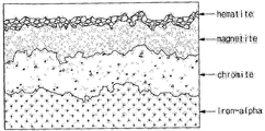
- Figure 4 is an enlarged cross-sectional view of the scale generated on the inner surface of the boiler tube according to the present invention.
- FIG. 1 is a flow chart illustrating a method of descaling a boiler tube according to the present invention
- Figure 4 is an enlarged cross-sectional view of the scale generated on the inner surface of the boiler tube according to the present invention.
- the descaling method of the boiler tube according to the present invention includes a physical cleaning step (S1), a scale detachment, a transfer step (S2) and a chemical cleaning step (S3).
- the physical cleaning step S1 is a step of physically cracking the scale generated on the inner surface of the boiler tube.
- the physical cleaning step (S1) is to remove the outer layer of the scale (hematite (magnetite) + magnetite) of the inner scale generated in the boiler tube as shown in Figure 4 primarily by physical method (temperature) To be generated.
- the scale detachment and transfer step S2 flushes the inside of the boiler tube using coolant having a low temperature. Therefore, the scale in which the crack has occurred in the physical cleaning step (S1) is detached from the boiler tube, at the same time transported, and discharged to the outside of the tube.
- the cooling water is a fluid having a flow rate of 0.5 kPa or more at a temperature of approximately 20 ° C., and it is possible to detach the scale from the boiler tube by the instantaneous pressure and temperature difference.
- the scale detachment, transfer step (S2) includes a step of discharging the scale detached by the flushing process to the outside using an electromagnet.
- Figure 2 is a schematic diagram showing an electromagnet for discharging the scale of the boiler tube according to the present invention to the outside.
- the electromagnet 100 is first section 10a of the outer surface of the boiler tube 10.
- the second section 10b and the third section 10c are sequentially moved.
- the residual scale inside the boiler tube 10 may be discharged to the outside of the boiler tube 10.
- the present invention is the first electromagnet 110, the second electromagnet 120 fixed to the first section 10a, the second section 10b and the third section 10c of the outer surface of the boiler tube 10, respectively. And by allowing the third electromagnet 130 to be magnetically sequentially, it is also possible to effectively transfer and discharge the remaining scale inside the boiler tube (10).
- Figure 3a is a side view showing a chemical cleaning device coupled to the boiler tube according to the present invention
- Figure 3b is a side view showing a cleaning solution injection device according to the present invention
- Figure 3c shows a cleaning solution injection device according to the present invention
- 3D is a front view showing a cleaning solution dispersing apparatus according to the present invention.
- the chemical cleaning step (S3) is a step of connecting the chemical cleaning device 200 to the boiler tube 10, and heating the temperature of the boiler tube 10 to perform chemical cleaning. Thereby, the inner layer of the scale (magnetite + chromite) can be detached from the boiler tube 10.
- the chemical cleaning device 200 includes a cleaning solution injecting device 210 and a cleaning solution dispersing device 220, and enhances the cleaning solution (not shown) at a flow rate of about 0.5 kPa or more and a pressure of 20 kg / cm 2 to provide a boiler tube ( 10) Circulate in and remove scale.
- the cleaning solution injection device 210 is installed in the circumferential direction round the cleaning solution injection portion 211 at intervals of 120 degrees so that the cleaning chemicals having a predetermined volume is mixed well to remove the scale remaining in the boiler tube (10)
- the cleaning solution may be compressed and sprayed using a compressor (not shown).
- the cleaning solution injection device 210 includes a flange 212 having a plurality of fasteners 212a to be fastened to the boiler tube 10. Therefore, since the cleaning solution injector 210 is coupled by mechanical coupling such as the boiler tube 10 and the bolt / nut, it may be easily attached and detached.
- the cleaning solution dispersion device 220 is installed between the cleaning solution injection device 210 and the boiler tube 10.
- the cleaning solution dispersing device 220 includes various types of clamp plates 221 in areas spaced at the ends of the cleaning solution injecting unit 211 so that the cleaning solution is well mixed.
- the cleaning solution dispersing device 220 is coupled to the boiler tube 10 by mechanical fastening such as bolts / nuts, and thus may be easily attached and detached.
- the present invention can be mounted directly to the boiler tube 10 in the field in the chemical cleaning device 200, so that the scale of the entire superheater and reheater uniformly without replacing the problematic boiler tube 10 in the present manner It causes the effect of removing, and can improve the cleaning efficiency during chemical cleaning.
Landscapes
- Engineering & Computer Science (AREA)
- Mechanical Engineering (AREA)
- Chemical & Material Sciences (AREA)
- Combustion & Propulsion (AREA)
- General Engineering & Computer Science (AREA)
- Physics & Mathematics (AREA)
- Thermal Sciences (AREA)
- Cleaning By Liquid Or Steam (AREA)
- Cleaning In General (AREA)
Abstract
본 발명은 보일러 튜브의 난용성 스케일을 효과적으로 용해하여 동시에 모재의 부식을 최소화하는 물리적, 화학적 세정 효율을 극대화할 수 있는 최적의 순환공정을 포함하는 보일러 튜브의 스케일 제거 방법을 제공한다. 이를 위해 본 발명은 보일러 튜브를 급속하게 냉각하여 내면에 생성된 스케일에 균열이 발생하도록 감온 시키는 제 1 단계, 상기 제 1 단계 후, 냉각수로 플러싱하여, 상기 스케일을 상기 보일러 튜브에서 탈리 시키고, 이송 시키는 제 2 단계 및 상기 제 2 단계 후, 상기 보일러 튜브에 세정용액 주입장치를 연결하고, 상기 보일러의 온도를 승온시켜 화학세정을 실시하는 제 3 단계를 포함하는 것을 특징으로 하는 보일러 튜브의 스케일 제거 방법을 개시한다.
Description
본 발명은 보일러 튜브의 스케일 제거 방법에 관한 것이다.
오랜 시간 동안 보일러를 운전하게 되면 보일러의 튜브 내면에 스케일이 축적되며 과열과 부식에 의한 손상과 같은 문제점을 발생시키고 보일러의 효율을 저하시킨다.
현재의 방식대로 문제 있는 튜브들을 교체한다 하더라도 교체하지 않은 부분이 남아 있어 스케일이 균일하게 제거되는 것도 아니며 재질의 특성이나 보일러의 특성이 달라지는 것도 아니므로 교체하지 않은 부분에서 발생하는 파열사고의 가능성은 잠재하고 있다. 과도한 스케일의 발생이나 신규 석탄 화력발전소의 다량 탈리에 의한 터빈의 손상은 아직 정밀하게 조사된 적은 없으나 향후 심각한 문제를 일으킬 수 있다. 그러므로 과열기와 재열기 전체의 스케일을 균일하게 제거하는 것이 필수적이며, 그 방법으로 화학세정법이 가장 우수하다.
본 발명은 보일러 튜브의 난용성 스케일을 효과적으로 용해하여 동시에 모재의 부식을 최소화하는 물리적, 화학적 세정 효율을 극대화할 수 있는 최적의 순환공정을 포함하는 보일러 튜브의 스케일 제거 방법을 제공한다.
본 발명에 따른 보일러 튜브의 스케일 제거 방법은 보일러 튜브를 급속하게 냉각하여 내면에 생성된 스케일에 균열이 발생하도록 감온 시키는 제 1 단계, 상기 제 1 단계 후, 냉각수로 플러싱하여, 상기 스케일을 상기 보일러 튜브에서 탈리 시키고, 이송 시키는 제 2 단계 및 상기 제 2 단계 후, 상기 보일러 튜브에 세정용액 주입장치를 연결하고, 상기 보일러의 온도를 승온시켜 화학세정을 실시하는 제 3 단계를 포함한다.
상기 제 2 단계는 상기 플러싱 후, 상기 보일러 튜브의 외면에서 전자석을 순차적으로 이동하여, 잔여 스케일을 상기 보일러 튜브의 외부로 배출할 수 있다. 상기 세정용액 주입장치는 원주 방향으로 120도 간격마다 설치된 세정용액 주입구를 포함할 수 있다. 상기 세정용액 주입장치는 프렌지를 구비하여, 상기 보일러 튜브에 체결될 수 있다. 상기 세정용액 주입장치와 상기 보일러 튜브의 사이에는 세정용액 분산 장치가 설치될 수 있다. 상기 세정용액 분산 장치는 내부에 뒤틀린 꺽쇠 형태의 플레이트를 구비할 수 있다.
본 발명은 보일러 튜브의 난용성 스케일을 효과적으로 용해하며, 동시에 모재의 부식을 최소화하는 물리적, 화학적 세정 효율을 극대화할 수 있는 최적의 순환공정을 제공할 수 있다.
도 1은 본 발명에 따른 보일러 튜브의 스케일 제거 방법을 도시한 흐름도이다.
도 2는 본 발명에 따른 보일러 튜브의 스케일을 외부로 배출하는 전자석을 도시한 모식도이다.
[규칙 제91조에 의한 정정 13.11.2013]
도 3a는 본 발명에 따른 보일러 튜브에 결합된 화학적 세정 장치를 도시한 측면도이고, 도 3b는 본 발명에 따른 세정용액 주입장치 도시한 측면도이고, 도 3c는 본 발명에 따른 세정용액 주입장치 도시한 정면도이고, 도 3d는 본 발명에 따른 세정용액 분산 장치를 도시한 정면도이고, 도 4는 본 발명에 따른 보일러 튜브의 내면에서 생성된 스케일을 확대한 단면도이다.
도 3a는 본 발명에 따른 보일러 튜브에 결합된 화학적 세정 장치를 도시한 측면도이고, 도 3b는 본 발명에 따른 세정용액 주입장치 도시한 측면도이고, 도 3c는 본 발명에 따른 세정용액 주입장치 도시한 정면도이고, 도 3d는 본 발명에 따른 세정용액 분산 장치를 도시한 정면도이고, 도 4는 본 발명에 따른 보일러 튜브의 내면에서 생성된 스케일을 확대한 단면도이다.
이하, 본 발명이 속하는 기술 분야에서 통상의 지식을 가진 자가 본 발명을 용이하게 실시할 수 있을 정도로 본 발명의 바람직한 실시예를 첨부된 도면을 참조하여 상세하게 설명하면 다음과 같다.
[규칙 제91조에 의한 정정 13.11.2013]
도 1은 본 발명에 따른 보일러 튜브의 스케일 제거 방법을 도시한 흐름도이고, 도 4는 본 발명에 따른 보일러 튜브의 내면에서 생성된 스케일을 확대한 단면도이다.
도 1은 본 발명에 따른 보일러 튜브의 스케일 제거 방법을 도시한 흐름도이고, 도 4는 본 발명에 따른 보일러 튜브의 내면에서 생성된 스케일을 확대한 단면도이다.
[규칙 제91조에 의한 정정 13.11.2013]
본 발명에 따른 보일러 튜브의 스케일 제거 방법은 도 1 및 도 4를 함께 참조하면, 물리적 세정 단계(S1), 스케일 탈리, 이송 단계(S2) 및 화학적 세정 단계(S3)를 포함한다.
본 발명에 따른 보일러 튜브의 스케일 제거 방법은 도 1 및 도 4를 함께 참조하면, 물리적 세정 단계(S1), 스케일 탈리, 이송 단계(S2) 및 화학적 세정 단계(S3)를 포함한다.
상기 물리적 세정 단계(S1)는 보일러 튜브의 내면에 생성되는 스케일에 물리적으로 균열을 발생시키는 단계이다.
[규칙 제91조에 의한 정정 13.11.2013]
[규칙 제91조에 의한 정정 13.11.2013]
[규칙 제91조에 의한 정정 13.11.2013]
[규칙 제91조에 의한 정정 13.11.2013]
상기 물리적 세정 단계(S1)는 도 4와 같이 보일러 튜브에서 생성된 내면 스케일 중 스케일의 외층(헤마타이트(hematite)+마그네타이트(magnetite))을 제거하기 1차적으로 물리적 방법(온도)에 의하여 크랙이 발생되도록 한다.
상기 물리적 세정 단계(S1)는 도 4와 같이 보일러 튜브에서 생성된 내면 스케일 중 스케일의 외층(헤마타이트(hematite)+마그네타이트(magnetite))을 제거하기 1차적으로 물리적 방법(온도)에 의하여 크랙이 발생되도록 한다.
상기 스케일의 외층(헤마타이트+마그네타이트)은 보일러 튜브를 10℃/min의 속도로 100℃ 이하까지 낮추면, 상기 보일러 튜브와 상기 스케일의 외층의 열전도도 차이에 의하여 크랙이 발생한다.
상기 스케일 탈리, 이송 단계(S2)는 온도가 낮은 냉각수를 이용해 보일러 튜브 내부를 플러싱한다. 따라서, 상기 물리적 세정 단계(S1)에서 크랙이 발생한 스케일을 보일러 튜브에서 탈리함과 동시에, 이송하여, 튜브 외부로 배출한다.
상기 냉각수는 대략 20℃의 온도로 0.5㎧ 이상의 유속을 가지는 유체로, 순간적인 압력과 온도 차이에 의해, 스케일을 보일러 튜브에서 탈리하는 것이 가능하다.
또한, 상기 스케일 탈리, 이송 단계(S2)는 플러싱 공정에 의해 탈리된 스케일을 전자석을 이용해 외부로 배출하는 공정을 포함한다.
도 2는 본 발명에 따른 보일러 튜브의 스케일을 외부로 배출하는 전자석을 도시한 모식도이다.
상기 스케일 탈리, 이송 단계(S2)에서는 도 2를 참조하면, 보일러 튜브(10) 내부의 잔여 스케일을 효과적으로 배출하기 위해, 전자석(100)을 보일러 튜브(10)의 외면의 제 1 구간(10a), 제 2 구간(10b) 및 제 3 구간(10c)을 순차적으로 이동 시킨다. 이로써, 보일러 튜브(10) 내부의 잔여 스케일은 보일러 튜브(10) 외부로 배출될 수 있다.
또한, 본 발명은 보일러 튜브(10)의 외면의 제 1 구간(10a), 제 2 구간(10b) 및 제 3 구간(10c)에 각각 고정된 제 1 전자석(110), 제 2 전자석(120) 및 제 3 전자석(130)이 순차적으로 자성을 띄게 하여, 보일러 튜브(10) 내부의 잔여 스케일을 효과적으로 이송, 배출하는 것도 가능하다.
도 3a는 본 발명에 따른 보일러 튜브에 결합된 화학적 세정 장치를 도시한 측면도이고, 도 3b는 본 발명에 따른 세정용액 주입장치 도시한 측면도이고, 도 3c는 본 발명에 따른 세정용액 주입장치 도시한 정면도이고, 도 3d는 본 발명에 따른 세정용액 분산 장치를 도시한 정면도이다.
이하에서는 도 3a 내지 도 3d를 참조하여, 상기 화학적 세정 단계(S3)를 설명한다.
상기 화학적 세정 단계(S3)는 상기 보일러 튜브(10)에 화학적 세정 장치(200)를 연결하고, 상기 보일러 튜브(10)의 온도를 승온시켜 화학세정을 실시하는 단계이다. 이로써, 스케일의 내층(마그네타이트+크로마이트(chromite))를 보일러 튜브(10)로부터 탈리 시킬 수 있다.
상기 화학적 세정 장치(200)는 세정용액 주입장치(210)와 세정용액 분산 장치(220)를 포함하여, 세정용액(미도시)을 대략 0.5㎧ 이상의 유속과 20kg/㎠ 압력으로 증강시켜 보일러 튜브(10) 내에서 순환시키고 스케일을 제거한다.
상기 세정용액 주입장치(210)는 보일러 튜브(10) 안에 남아있는 스케일을 제거하기 위해 일정 용량을 가지는 세정약품이 혼합이 잘되도록 세정용액 주입 부(211)를 120도 간격으로 원주방향으로 둥글게 설치하고 압축기(미도시)를 이용 세정용액을 압축하여 분사할 수 있다.
상기 세정용액 주입장치(210)는 보일러 튜브(10)에 체결할 수 있도록 다수의 체결구(212a)를 구비하는 프렌지(212)를 포함한다. 따라서, 세정용액 주입장치(210)는 보일러 튜브(10)와 볼트/너트와 같은 기계적 체결에 의해 결합하므로, 탈부착이 용이할 수 있다.
상기 세정용액 분산 장치(220)는 세정용액 주입장치(210)와 보일러 튜브(10) 사이에 설치된다.
상기 세정용액 분산 장치(220)는 세정용액이 혼합이 잘되도록 세정용액 주입부(211)의 끝단에 이격된 지역에, 여러 형태의 꺽쇠 플레이트(221)를 구비한다.
또한, 상기 세정용액 주입장치(210)와 마찬가지로 보일러 튜브(10)에 체결할 수 있도록 보일러 튜브(10)에 체결할 수 있도록 다수의 체결구(222a)를 구비하는 프렌지(222)를 포함한다. 따라서, 세정용액 분산 장치(220)는 보일러 튜브(10)와 볼트/너트와 같은 기계적 체결에 의해 결합하므로, 탈부착이 용이할 수 있다.
따라서 본 발명은 화학적 세정 장치(200)를 현장에서 보일러 튜브(10)에 직접 장착할 수 있어, 현재의 방식대로 문제 있는 보일러 튜브(10)를 교체하지 않으며 과열기와 재열기 전체의 스케일을 균일하게 제거하는 효과를 야기하며, 화학 세정 시 세정 효율을 향상할 수 있다.
본 발명은 상기 실시 예들에 한정되지 않고 본 발명의 기술적 요지를 벗어나지 아니하는 범위 내에서 다양하게 수정, 변형되어 실시될 수 있음은 본 발명이 속하는 기술분야에서 통상의 지식을 가진 자에 있어서 자명한 것이다.
Claims (6)
- 보일러 튜브를 급속하게 냉각하여 내면에 생성된 스케일에 균열이 발생하도록 감온 시키는 제 1 단계;상기 제 1 단계 후, 냉각수로 플러싱하여, 상기 스케일을 상기 보일러 튜브에서 탈리 시키고, 이송 시키는 제 2 단계; 및상기 제 2 단계 후, 상기 보일러 튜브에 세정용액 주입장치를 연결하고, 상기 보일러의 온도를 승온시켜 화학세정을 실시하는 제 3 단계; 를 포함하는 것을 특징으로 하는 보일러 튜브의 스케일 제거 방법.
- 제 1항에 있어서,상기 제 2 단계는상기 플러싱 후, 상기 보일러 튜브의 외면에서 전자석을 순차적으로 이동하여, 잔여 스케일을 상기 보일러 튜브의 외부로 배출하는 것을 특징으로 하는 보일러 튜브의 스케일 제거 방법.
- 제 1항에 있어서,상기 세정용액 주입장치는원주 방향으로 120도 간격마다 설치된 세정용액 주입구를 포함하는 것을 특징으로 하는 보일러 튜브의 스케일 제거 방법.
- 제 1항 또는 제 3항에 있어서,상기 세정용액 주입장치는 프렌지를 구비하여, 상기 보일러 튜브에 체결되는 것을 특징으로 하는 보일러 튜브의 스케일 제거 방법.
- 제 4항에 있어서,상기 세정용액 주입장치와 상기 보일러 튜브의 사이에는 세정용액 분산 장치가 설치되는 것을 특징으로 하는 보일러 튜브의 스케일 제거 방법.
- 제 5항에 있어서,상기 세정용액 분산 장치는 내부에 뒤틀린 꺽쇠 형태의 플레이트를 구비하는 것을 특징으로 하는 보일러 튜브의 스케일 제거 방법.
Applications Claiming Priority (2)
| Application Number | Priority Date | Filing Date | Title |
|---|---|---|---|
| KR1020120109118A KR101426403B1 (ko) | 2012-09-28 | 2012-09-28 | 보일러 튜브의 스케일 제거 방법 |
| KR10-2012-0109118 | 2012-09-28 |
Publications (1)
| Publication Number | Publication Date |
|---|---|
| WO2014051280A1 true WO2014051280A1 (ko) | 2014-04-03 |
Family
ID=50388605
Family Applications (1)
| Application Number | Title | Priority Date | Filing Date |
|---|---|---|---|
| PCT/KR2013/008244 Ceased WO2014051280A1 (ko) | 2012-09-28 | 2013-09-12 | 보일러 튜브의 스케일 제거 방법 |
Country Status (2)
| Country | Link |
|---|---|
| KR (1) | KR101426403B1 (ko) |
| WO (1) | WO2014051280A1 (ko) |
Families Citing this family (1)
| Publication number | Priority date | Publication date | Assignee | Title |
|---|---|---|---|---|
| KR20160009127A (ko) | 2014-07-15 | 2016-01-26 | 한국전력공사 | 표면처리 장치 및 관내 표면처리 방법 |
Citations (4)
| Publication number | Priority date | Publication date | Assignee | Title |
|---|---|---|---|---|
| JPH0633981B2 (ja) * | 1987-06-23 | 1994-05-02 | 株式会社マリンリバー | 熱交換器のスケ−ル除去方法 |
| JPH06294594A (ja) * | 1993-04-07 | 1994-10-21 | Mitsubishi Heavy Ind Ltd | 給水加熱器の化学洗浄方法 |
| JPH0842993A (ja) * | 1994-08-01 | 1996-02-16 | S K A Kk | スケールの除去・防止装置 |
| KR200253472Y1 (ko) * | 2001-08-01 | 2001-11-22 | 주식회사 씨플랜트 | 전자식 스케일 방지 장치 |
Family Cites Families (1)
| Publication number | Priority date | Publication date | Assignee | Title |
|---|---|---|---|---|
| GB2095749B (en) * | 1981-03-25 | 1984-12-12 | Rolls Royce | Gas turbine engine having improved resistance for foreign object ingestion damage |
-
2012
- 2012-09-28 KR KR1020120109118A patent/KR101426403B1/ko active Active
-
2013
- 2013-09-12 WO PCT/KR2013/008244 patent/WO2014051280A1/ko not_active Ceased
Patent Citations (4)
| Publication number | Priority date | Publication date | Assignee | Title |
|---|---|---|---|---|
| JPH0633981B2 (ja) * | 1987-06-23 | 1994-05-02 | 株式会社マリンリバー | 熱交換器のスケ−ル除去方法 |
| JPH06294594A (ja) * | 1993-04-07 | 1994-10-21 | Mitsubishi Heavy Ind Ltd | 給水加熱器の化学洗浄方法 |
| JPH0842993A (ja) * | 1994-08-01 | 1996-02-16 | S K A Kk | スケールの除去・防止装置 |
| KR200253472Y1 (ko) * | 2001-08-01 | 2001-11-22 | 주식회사 씨플랜트 | 전자식 스케일 방지 장치 |
Also Published As
| Publication number | Publication date |
|---|---|
| KR101426403B1 (ko) | 2014-08-07 |
| KR20140042395A (ko) | 2014-04-07 |
Similar Documents
| Publication | Publication Date | Title |
|---|---|---|
| CN101109088A (zh) | 一种酸再生机组内循环式管道酸垢清洗工艺 | |
| CN103256835A (zh) | 一种可方便壳程清洗的管壳式换热器 | |
| WO2014051280A1 (ko) | 보일러 튜브의 스케일 제거 방법 | |
| CN106148981A (zh) | 一种采用化学方法清洗磷酸管道结垢的装置 | |
| CN204007240U (zh) | 一种冷凝器 | |
| CN103851953B (zh) | 管式换热器独立小流量循环化学除垢法 | |
| CN205436423U (zh) | 换热器在线喷淋清洗装置 | |
| CN205347468U (zh) | 一种高炉冷却壁修复装置 | |
| CN201387206Y (zh) | 一种真空冷冻干燥箱 | |
| CN211012654U (zh) | 板式换热器清洗系统 | |
| CN203464843U (zh) | 一种冷却器除垢装置 | |
| CN104438243B (zh) | 一种单套管预热器内管结疤的清理方法 | |
| CN103322825A (zh) | 一种水泥生产结皮清理方法 | |
| CN119085369A (zh) | 一种管式换热器 | |
| CN201331293Y (zh) | 用于石墨列管式换热器快速堵漏的堵头 | |
| CN102580958B (zh) | 管式蒸发器高压水清洗水枪夹持装置的使用方法 | |
| CN103925700B (zh) | 一种防止油田加热炉火管结垢的装置 | |
| CN207025099U (zh) | 一种反渗透膜拆卸系统 | |
| CN213898904U (zh) | 一种用于井下油管清洗系统的碱洗装置 | |
| CN205037792U (zh) | 用于金属件淬、回火介质热交换的分体式列管冷却器 | |
| CN204630468U (zh) | 一种果葡糖浆生产过程中换热器清洗系统 | |
| CN217726529U (zh) | 一种串油管路加热装置 | |
| CN204006685U (zh) | 一种防止油田加热炉火管结垢的结构 | |
| CN204022950U (zh) | 一种恒温酸洗槽 | |
| CN216460649U (zh) | 一种管道安装阻垢缓蚀装置 |
Legal Events
| Date | Code | Title | Description |
|---|---|---|---|
| 121 | Ep: the epo has been informed by wipo that ep was designated in this application |
Ref document number: 13841965 Country of ref document: EP Kind code of ref document: A1 |
|
| NENP | Non-entry into the national phase |
Ref country code: DE |
|
| 32PN | Ep: public notification in the ep bulletin as address of the adressee cannot be established |
Free format text: NOTING OF LOSS OF RIGHTS PURSUANT TO RULE 112(1) EPC (EPO FORM 1205A DATED 15/07/2015) |
|
| 122 | Ep: pct application non-entry in european phase |
Ref document number: 13841965 Country of ref document: EP Kind code of ref document: A1 |