WO2014049845A1 - 画像処理装置および電子部品実装機 - Google Patents
画像処理装置および電子部品実装機 Download PDFInfo
- Publication number
- WO2014049845A1 WO2014049845A1 PCT/JP2012/075138 JP2012075138W WO2014049845A1 WO 2014049845 A1 WO2014049845 A1 WO 2014049845A1 JP 2012075138 W JP2012075138 W JP 2012075138W WO 2014049845 A1 WO2014049845 A1 WO 2014049845A1
- Authority
- WO
- WIPO (PCT)
- Prior art keywords
- data
- unit
- image
- frequency
- image data
- Prior art date
- Legal status (The legal status is an assumption and is not a legal conclusion. Google has not performed a legal analysis and makes no representation as to the accuracy of the status listed.)
- Ceased
Links
Images


Classifications
-
- H—ELECTRICITY
- H04—ELECTRIC COMMUNICATION TECHNIQUE
- H04N—PICTORIAL COMMUNICATION, e.g. TELEVISION
- H04N19/00—Methods or arrangements for coding, decoding, compressing or decompressing digital video signals
- H04N19/30—Methods or arrangements for coding, decoding, compressing or decompressing digital video signals using hierarchical techniques, e.g. scalability
-
- H—ELECTRICITY
- H04—ELECTRIC COMMUNICATION TECHNIQUE
- H04N—PICTORIAL COMMUNICATION, e.g. TELEVISION
- H04N1/00—Scanning, transmission or reproduction of documents or the like, e.g. facsimile transmission; Details thereof
- H04N1/41—Bandwidth or redundancy reduction
-
- H—ELECTRICITY
- H04—ELECTRIC COMMUNICATION TECHNIQUE
- H04N—PICTORIAL COMMUNICATION, e.g. TELEVISION
- H04N19/00—Methods or arrangements for coding, decoding, compressing or decompressing digital video signals
- H04N19/60—Methods or arrangements for coding, decoding, compressing or decompressing digital video signals using transform coding
- H04N19/625—Methods or arrangements for coding, decoding, compressing or decompressing digital video signals using transform coding using discrete cosine transform [DCT]
-
- H—ELECTRICITY
- H04—ELECTRIC COMMUNICATION TECHNIQUE
- H04N—PICTORIAL COMMUNICATION, e.g. TELEVISION
- H04N19/00—Methods or arrangements for coding, decoding, compressing or decompressing digital video signals
- H04N19/80—Details of filtering operations specially adapted for video compression, e.g. for pixel interpolation
-
- H—ELECTRICITY
- H04—ELECTRIC COMMUNICATION TECHNIQUE
- H04N—PICTORIAL COMMUNICATION, e.g. TELEVISION
- H04N19/00—Methods or arrangements for coding, decoding, compressing or decompressing digital video signals
- H04N19/85—Methods or arrangements for coding, decoding, compressing or decompressing digital video signals using pre-processing or post-processing specially adapted for video compression
Definitions
- the present invention relates to an image processing apparatus that compresses image data, and an electronic component mounting machine including the image processing apparatus.
- Patent Document 1 discloses a configuration in which a control device connected to an imaging device performs image processing in an electronic component mounter that mounts electronic components on a substrate.
- the control device of the electronic component mounting machine performs image processing such as edge detection on the image data acquired by the imaging device. Then, the control device recognizes the board position and the posture of the electronic component based on the processing result to improve the accuracy of the mounting control.
- Patent Document 2 discloses an imaging apparatus that transfers image data after JPEG compression. According to JPEG compression of image data, it is possible to reduce the data size because a high compression rate can be obtained.
- JPEG compression it is known that block noise occurs because image data is compressed in units of blocks. JPEG compression uses the fact that signal energy is biased toward low frequency components at the spatial frequency of image data, and obtains a high compression rate by reducing high frequency components. For this reason, the information on the edge portion included in the high-frequency component is attenuated, and the edge portion in the image data is blurred. Therefore, when performing image processing such as edge detection, compression processing suitable for image processing is required, and the compression rate may not be set higher than usual.
- the present invention has been made in view of such circumstances, and provides an image processing apparatus capable of reducing block noise and capable of JPEG compression suitable for image processing, and an electronic component mounting machine including the image processing apparatus. For the purpose.
- An image processing apparatus includes: a smoothing unit that attenuates a high-frequency component of image data to generate smoothed data; and a JPEG compression unit that performs JPEG compression of the smoothed data to generate JPEG compressed data.
- a high-frequency extraction unit that generates high-frequency extraction data composed of high-frequency components of the image data, a high-frequency compression unit that encodes the high-frequency extraction data to generate high-frequency compression data, the JPEG compression data, and the high-frequency data
- a data combining unit that combines the compressed data.
- the image processing apparatus attenuates the high frequency component of the image data by the smoothing unit before compressing the image data by the JPEG compression unit.
- variations in luminance values in the image data are reduced. Therefore, when the JPEG compression unit performs compression processing in units of blocks, the difference in luminance value between adjacent blocks is reduced. Therefore, the JPEG compression unit can JPEG compress the smoothed data at a high compression rate while suppressing the occurrence of block noise.
- the image processing apparatus extracts the high frequency component from the image data before the high frequency component is attenuated.
- the data combining unit is configured to combine the JPEG compressed data and the high frequency compressed data obtained by encoding the high frequency extracted data. This makes it possible to supplement high-frequency components that are reduced by smoothing and JPEG compression. That is, by combining the high frequency extraction data, information on the edge portion included in the high frequency component is supplemented. Therefore, the image processing apparatus can perform compression processing suitable for image processing.
- the high-frequency extraction unit generates the high-frequency extraction data by performing a difference calculation between the image data and the smoothed data.
- the high frequency extraction unit can generate high frequency extraction data corresponding to a high frequency component attenuated by smoothing.
- Various methods such as filter processing can be considered as extraction of high-frequency components from image data.
- adjustment according to each extraction method is required, for example, raising or lowering the filtering frequency.
- the image processing apparatus can simplify the extraction of the high-frequency component and can extract the high-frequency component actually attenuated by the smoothing from the image data by adopting the configuration as described above.
- An electronic component mounting machine includes the image processing apparatus according to the first or second aspect, and an image pickup apparatus that compresses and records the image data acquired by image pickup, and is connected to be communicable with the image pickup apparatus.
- a control device that acquires the image data that has been compressed from the imaging device, and controls mounting of electronic components based on restoration data obtained by restoration processing on the image data and a control program stored in advance; Is provided.
- the control device includes a data dividing unit that divides the compressed image data into the JPEG compressed data and the high-frequency compressed data, a JPEG expanding unit that expands the JPEG compressed data to generate the smoothed data, A high-frequency decoding unit that decodes the high-frequency compressed data to generate the high-frequency extracted data; and performs an addition operation of the smoothed data and the high-frequency extracted data to restore the image data and generate the restored data And an addition operation unit.
- the image processing device of the control device can perform the addition operation of the smoothed data and the high frequency extracted data to restore the image data, and generate restored data supplemented with the high frequency components.
- the restored data is supplemented with information on the edge portion included in the high frequency component. Therefore, the image processing apparatus can perform image processing such as edge detection with high accuracy. Therefore, the electronic component mounting machine can further improve the accuracy of mounting control by using the processing result.
- FIGS. 1 and 2 exemplifies a configuration in which an image processing apparatus that performs image processing such as image data compression processing, decompression processing, and edge detection is used as an imaging device and a control device of an electronic component mounting machine.
- image processing apparatus that performs image processing such as image data compression processing, decompression processing, and edge detection is used as an imaging device and a control device of an electronic component mounting machine.
- the electronic component mounting machine 1 is a device that mounts a plurality of electronic components on a printed circuit board, for example, in an integrated circuit manufacturing process. Solder is applied to the mounting position of the electronic component by the cream solder printing machine, and the printed circuit board is sequentially transported through a plurality of mounting machines to mount the electronic component. Thereafter, the printed circuit board on which the electronic components are mounted is transported to a reflow furnace and soldered to constitute an integrated circuit.
- the camera 3 is an imaging device for FA incorporated in the electronic component mounting machine 1.
- the electronic component mounting machine 1 includes a control device 2 and a camera 3 as shown in FIG.
- the control device 2 and the camera 3 are communicably connected via a communication cable 4 so that various signals can be transmitted and received.
- the image processing apparatus includes the CPU 10 of the control device 2 and the CPU 40 of the camera 3. This image processing apparatus compresses the image data acquired by the camera 3, and the control apparatus 2 decompresses the compressed image data to restore the image data.
- the control device 2 further performs image processing such as edge detection on the restored data, and uses the processing result for nozzle position correction in the mounting control.
- the control device 2 is a device that executes various control processes.
- the control device 2 includes a CPU 10 that constitutes a part of the image processing device, and a storage device 20.
- the CPU 10 inputs information output from various sensors provided in the electronic component mounting machine 1, compressed image data transmitted from the camera 3, and the like. Then, based on the control program stored in the storage device 20, information from various sensors, processing results by image processing, and the like, the CPU 10 of the electronic component mounting machine 1 can appropriately mount the electronic component on the printed circuit board. Controls each axis motor and each device.
- the CPU 10 of the control device 2 includes a data dividing unit 11, a JPEG developing unit 12, a high frequency decoding unit 13, and an addition operation unit 14.
- the image data transmitted from the camera 3 is combined data Cm generated by a compression process to be described later.
- This combined data Cm is a combination of JPEG compressed data Cj and high frequency compressed data Ch.
- Each of the units 11 to 14 of the CPU 10 performs restoration processing for generating restoration data Re by dividing, decompressing, decoding, and the like on the combined data Cm. Details of the units 11 to 14 of the CPU 10 will be described later.
- the CPU 10 constituting a part of the image processing apparatus executes image processing corresponding to the use for the restored data Re.
- This image processing includes, for example, processing such as binarization, filtering, and hue extraction of the restored image data, and the presence / absence of the subject and position information based on a specific shape or mark from the processed image data Recognition processing is included.
- the CPU 10 performs image processing for detecting edges in the restored image data.
- the storage device 20 of the control device 2 is configured by an optical drive device such as a hard disk device or a flash memory.
- the storage device 20 stores a control program for operating the electronic component mounting machine 1, image data transmitted from the camera 3 to the CPU 10 via the communication cable 4, temporary data for image processing, and the like.
- the camera 3 includes an optical unit 30, a CPU 40, and a storage device 50.
- the optical unit 30 has a configuration in which subject light is imaged on an image sensor 32 by a lens unit 31 including a lens and a lens holding member.
- the image sensor 32 is mounted on the circuit board so as to be perpendicular to the optical axis of the lens unit 31.
- the image sensor 32 is an image sensor such as a CCD (Charge-Coupled Device) or a CMOS (Complementary-Metal-Oxide-Semiconductor).
- the CPU 40 of the camera 3 performs imaging by operating the optical unit 30 based on a control signal input from the control device 2. More specifically, the CPU 40 controls the optical unit 30 based on a signal input from the outside or a control command input from the control device 2, and the light imaged on the imaging surface of the image sensor 32 by the lens unit 31. The subject is imaged by converting the signal charge generated according to the intensity of the signal into a digital signal. The CPU 40 converts the image data into image data based on the digital signal.
- the CPU 40 of the camera 3 constitutes a part of an image processing apparatus that performs image data compression processing before transferring image data acquired by imaging to the control apparatus 2.
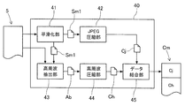
- the CPU 40 includes a smoothing unit 41, a JPEG compression unit 42, a high frequency extraction unit 43, a high frequency compression unit 44, and a data combination unit 45.
- Each of the units 41 to 45 of the CPU 40 performs processing such as smoothing, JPEG compression, and high-frequency extraction on the uncompressed image data to reduce the data size and to make the image data suitable for image processing in the control device 2. Convert. Details of the units 41 to 45 of the CPU 40 will be described later.
- the storage device 50 of the camera 3 is configured by a nonvolatile ROM, a volatile RAM, or the like.
- the nonvolatile ROM stores a program such as a driver for the CPU 40 to control the optical unit 30, initial setting data, and the like.
- the volatile RAM stores temporary data for image processing by the CPU 40 and the like.
- image data compression processing by image processing device Next, image data compression processing by the image processing apparatus of the electronic component mounting machine 1 will be described with reference to FIGS. 1 and 3.
- the image processing device (CPU 40) of the camera 3 performs imaging based on a command from the control device 2. Then, the image processing apparatus acquires image data 5 by the imaging as shown in FIG.
- the image data 5 is uncompressed data having a data size corresponding to the number of pixels.
- the smoothing unit 41 attenuates the high frequency component of the image data 5 to generate smoothed data Sm1.
- the high-frequency component in the image data 5 is a component including a higher frequency than a predetermined frequency among the spatial frequencies indicated by the values of the pixels constituting the image data 5.
- This high-frequency component corresponds to a portion or contour line where the change in luminance value (pixel value) is large in the image data 5 and includes, for example, information on an edge portion in the image data.
- the smoothing unit 41 calculates an average based on the values of each pixel around the target pixel, and attenuates the high frequency component by setting the average value as the value of the target pixel.
- a filtering process using a Gaussian filter using a Gaussian function or a low-pass filter is known as a method for attenuating a high frequency component.
- the smoothing unit 41 is configured to appropriately smooth the image data 5 by these methods.
- the JPEG compression unit 42 performs JPEG compression of the smoothed data Sm1 to generate JPEG compressed data Cj.
- This JPEG compression is a general compression process for converting image data into the JPEG format. More specifically, the JPEG compression unit 42 first divides the smoothed data Sm1 into fixed-size blocks and performs discrete cosine transform on each block. As a result, the smoothed data Sm1 is decomposed into a plurality of different frequency components.
- the JPEG compression unit 42 performs quantization by rounding the smoothed data Sm1 decomposed into each frequency component to an approximate integer using a predetermined quantization table. Thereby, the high frequency component in the smoothed data Sm1 is attenuated, and the data size is reduced. Further, the JPEG compression unit 42 performs entropy encoding using Huffman code on the smoothed data Sm1 that has been subjected to discrete cosine transform and quantization. As a result, the data size is further reduced, and JPEG compressed data Cj is generated by these processes.
- the smoothing data Sm1 subjected to JPEG compression has a high frequency component attenuated by the smoothing unit 41 in advance. Therefore, the frequency component of the smoothed data Sm1 is biased toward the low frequency side as compared with the case where the original image data 5 is JPEG compressed. In other words, in JPEG compression targeting such smoothed data Sm1, a higher compression rate can be expected than image data that has not been smoothed.
- the high frequency extraction unit 43 generates high frequency extraction data Ab composed of high frequency components of the image data 5.
- the high-frequency extraction unit 43 is configured to generate the high-frequency extraction data Ab by performing a difference calculation between the image data 5 and the smoothed data Sm1. More specifically, the difference for each pixel of the image data 5 and the smoothed data Sm1 is set as the value of each pixel in the high-frequency extraction data Ab.
- the high frequency extraction data Ab is composed of high frequency components attenuated by the smoothing unit 41.
- the high frequency compression unit 44 encodes the high frequency extracted data Ab to generate high frequency compressed data Ch. More specifically, the high frequency compression unit 44 performs compression by entropy encoding such as run length code or Huffman code. Thereby, the data size of the high frequency compression data Ch is reduced.
- the data combining unit 45 combines the JPEG compressed data Cj and the high frequency compressed data Ch. As a result, combined data Cm, which is one file, is generated.
- the image processing apparatus stores the combined data Cm in the storage device 50, and ends the compression process of the image data 5.
- image data restoration processing by image processing device Next, image data restoration processing by the image processing apparatus of the electronic component mounting machine 1 will be described with reference to FIGS. 1 and 2.
- the image processing device (CPU 10) of the control device 2 makes an imaging request and image data transfer request to the camera 3.
- the camera 3 captures an image according to an image capture request, and compresses and records the image data 5 acquired by the image capture as described above. Further, the camera 3 transfers the image data 5 compressed by the transfer request to the control device 2 via the communication cable 4.
- the image processing device of the control device 2 acquires the compressed image data 5 (combined data Cm) from the camera 3, and restores the combined data Cm to the restored data Re by a restoration process described later. To get.
- the control device 2 controls the mounting of the electronic component based on the restoration data Re obtained by the restoration process and a control program stored in advance.
- the data dividing unit 11 divides the compressed image data (combined data Cm) into JPEG compressed data Cj and high frequency compressed data Ch.
- the JPEG expansion unit 12 expands the one side JPEG compressed data Cj divided by the data division unit 11 to generate smoothed data Sm2.
- This JPEG expansion is a general expansion process for returning the JPEG format to image data. More specifically, the JPEG decompression unit 12 first decodes the entropy-encoded JPEG compressed data Cj corresponding to the Huffman code. Then, the JPEG decompression unit 12 performs inverse quantization on the decoded JPEG compressed data Cj using the same quantization table used by the camera 3 in the compression process of the image data 5.
- the JPEG decompression unit 12 divides the decoded and dequantized JPEG compressed data Cj into fixed-size blocks, and performs inverse discrete cosine transform on each block. Thereby, smoothed data Sm2 indicated by a plurality of types of frequency components is generated.
- the smoothed data Sm2 is obtained by restoring the smoothed data Sm1 generated by attenuating the high frequency component of the image data 5 in the image processing apparatus of the camera 3.
- the restored smoothed data Sm2 does not necessarily match the smoothed data Sm1 before compression. This is because a part of the smoothed data Sm1 is rounded to an approximate integer by quantization in the compression processing of the image data 5.
- the high frequency decoding unit 13 decodes the other high frequency compressed data Ch divided by the data dividing unit 11 to generate high frequency extraction data Ab. More specifically, the high frequency decoding unit 13 decodes the entropy-encoded high-frequency compressed data Ch corresponding to a run length code, a Huffman code, or the like in the compression process. If this entropy coding is lossless compression, the same high-frequency extraction data Ab as before compression is generated by the decoding.
- the addition operation unit 14 performs addition operation of the smoothed data Sm2 and the high-frequency extraction data Ab to restore the image data 5, and generate restored data Re. More specifically, the addition operation unit 14 adds the values for each pixel of the smoothed data Sm2 and the high-frequency extraction data Ab to obtain the sum as the value of each pixel in the restored data Re. Thereby, the restoration data Re supplemented with the high-frequency component attenuated by the smoothing of the smoothing unit 41 in the camera 3 is generated.
- the image processing apparatus stores the restoration data Re in the storage device 20, and ends the restoration processing of the image data 5.
- the image processing apparatus configured as described above attenuates the high frequency component of the image data 5 by the smoothing unit 41 before compressing the image data 5 by the JPEG compression unit 42.
- variations in luminance values (pixel values) in the image data 5 are reduced. Therefore, when the JPEG compression unit 42 performs the compression process in units of blocks, the difference between the luminance values of adjacent blocks becomes small. Therefore, the JPEG compression unit 42 can JPEG-compress the smoothed data Sm1 at a high compression rate while suppressing the occurrence of block noise.
- the image processing device (CPU 40) extracts a high frequency component from the image data 5 before the high frequency component is attenuated.
- the data combining unit 45 is configured to combine the JPEG compressed data Cj and the high frequency compressed data Ch obtained by encoding the high frequency extracted data Ab. This makes it possible to supplement high-frequency components that are reduced by smoothing and JPEG compression. That is, by combining the high frequency extraction data Ab, information on the edge portion included in the high frequency component is supplemented. Therefore, the image processing apparatus (CPU 40) can perform compression processing suitable for image processing.
- the high frequency extraction unit 43 generates high frequency extraction data Ab by performing a difference calculation between the image data 5 and the smoothed data Sm1. Thereby, the high frequency extraction part 43 can simplify extraction of a high frequency component. Furthermore, the high frequency extraction unit 43 can generate the high frequency extraction data Ab by extracting the high frequency component actually attenuated by the smoothing from the image data 5.
- the image processing device (CPU 10) of the control device 2 performs the addition operation of the restored smoothed data Sm2 and the high frequency extraction data Ab to restore the image data 5 and generate the restored data Re.
- the image processing apparatus can acquire the restored data Re supplemented with the high frequency components.
- the restored data Re is supplemented with information on the edge portion included in the high frequency component. Therefore, the image processing apparatus (CPU 10) can perform image processing such as edge detection with high accuracy. Therefore, the electronic component mounting machine 1 can further improve the accuracy of mounting control by using the result of image processing such as edge detection.
- the high frequency extraction unit 43 generates the high frequency extraction data Ab by performing a difference calculation between the image data 5 and the smoothed data Sm1.
- the high frequency extraction unit 43 may generate the high frequency extraction data Ab by a method such as a filtering process using a high-pass filter, for example.
- the image processing apparatus has been described by exemplifying the configuration applied to the electronic component mounting machine 1.
- the image processing apparatus can be applied to various apparatuses and integrated circuits that handle image data in addition to the control apparatus 2 and the camera 3. Even in such a configuration, since the image data can be compressed at a higher compression rate than the uncompressed image data, the data size can be reduced. Therefore, it is possible to reduce the amount of memory used for recording the compressed image data, and to shorten the communication time when communicating with other devices.
Landscapes
- Engineering & Computer Science (AREA)
- Multimedia (AREA)
- Signal Processing (AREA)
- Physics & Mathematics (AREA)
- Discrete Mathematics (AREA)
- General Physics & Mathematics (AREA)
- Compression Or Coding Systems Of Tv Signals (AREA)
- Compression Of Band Width Or Redundancy In Fax (AREA)
- Image Processing (AREA)
Description
本発明は、画像データの圧縮を行う画像処理装置、および画像処理装置を備える電子部品実装機に関するものである。
画像処理装置は、画像データに対して種々の処理を行う装置として用いられる。例えば、特許文献1には、基板に電子部品を実装する電子部品実装機において、撮像装置と接続された制御装置が画像処理を行う構成が開示されている。この電子部品実装機の制御装置は、撮像装置により取得された画像データに対してエッジ検出などの画像処理を行う。そして、制御装置は、処理結果に基づいて基板位置や電子部品の姿勢を認識し、実装制御の精度向上を図っている。
ところで、画像処理の用途によっては高解像度の画像データが必要とされることがある。そうすると、画像データの画素数の増加に伴ってデータサイズが増加し、記録に要するメモリ容量の増加や、データ転送に要する時間が長くなることが懸念される。そこで、例えば、特許文献2には、画像データをJPEG圧縮して転送する撮像装置が開示されている。画像データのJPEG圧縮によると、高い圧縮率を得られるためデータサイズを低減することが可能とされている。
しかしながら、JPEG圧縮では、画像データをブロック単位で圧縮処理するため、ブロックノイズが生じることが知られている。また、JPEG圧縮は、画像データの空間周波数において信号エネルギーが低周波成分に偏っていることを利用し、高周波成分を削減することで高い圧縮率を得ている。そのため、高周波成分に含まれるエッジ部分の情報が減衰することになり、画像データにおけるエッジ部分がぼやけてしまうことになる。よって、エッジ検出などの画像処理を行う場合には、画像処理に適した圧縮処理が必要となり、通常よりも圧縮率を高く設定できないことがあった。
本発明は、このような事情を鑑みてなされたものであり、ブロックノイズを低減するとともに画像処理に適したJPEG圧縮が可能な画像処理装置、および画像処理装置を備える電子部品実装機を提供することを目的とする。
請求項1に係る画像処理装置は、画像データの高周波成分を減衰させて平滑化データを生成する平滑化部と、前記平滑化データのJPEG圧縮を行ってJPEG圧縮データを生成するJPEG圧縮部と、前記画像データの高周波成分により構成される高周波抽出データを生成する高周波抽出部と、前記高周波抽出データの符号化を行って高周波圧縮データを生成する高周波圧縮部と、前記JPEG圧縮データと前記高周波圧縮データとを結合するデータ結合部と、を備える。
このような構成によると、画像処理装置は、JPEG圧縮部により画像データを圧縮する前に、この画像データの高周波成分を平滑化部により減衰させるものとしている。これにより、画像データのおける輝度値のバラツキが軽減することになる。そのため、JPEG圧縮部がブロック単位で圧縮処理を行った場合に、隣り合うブロックの輝度値の差が小さくなる。よって、JPEG圧縮部は、ブロックノイズの発生を抑制しつつ、高い圧縮率で平滑化データをJPEG圧縮することができる。
また、画像処理装置は、高周波成分を減衰される前の画像データから高周波成分を抽出する。そして、データ結合部は、JPEG圧縮データと、高周波抽出データを符号化した高周波圧縮データとを結合する構成としている。これにより、平滑化およびJPEG圧縮により削減される高周波成分を補充することが可能となる。つまり、高周波抽出データを結合することで、高周波成分に含まれるエッジ部分の情報などが補充される。よって、画像処理装置は、画像処理に適した圧縮処理を行うことが可能となる。
請求項2に係る画像処理装置によると、前記高周波抽出部は、前記画像データと前記平滑化データの差分演算を行うことにより前記高周波抽出データを生成する。
このような構成によると、高周波抽出部は、平滑化により減衰した高周波成分に対応した高周波抽出データを生成することができる。画像データに対する高周波成分の抽出としては、フィルター処理などの種々の方法が考えられる。しかし、平滑化により実際に減衰する高周波成分に対応するためには、例えばフィルタリングの周波数を上下させるなど、各抽出方法に応じた調整が必要となる。これに対して、画像処理装置は、上記のような構成とすることで、高周波成分の抽出を簡易化できるとともに、平滑化により実際に減衰した高周波成分を画像データから抽出することができる。
このような構成によると、高周波抽出部は、平滑化により減衰した高周波成分に対応した高周波抽出データを生成することができる。画像データに対する高周波成分の抽出としては、フィルター処理などの種々の方法が考えられる。しかし、平滑化により実際に減衰する高周波成分に対応するためには、例えばフィルタリングの周波数を上下させるなど、各抽出方法に応じた調整が必要となる。これに対して、画像処理装置は、上記のような構成とすることで、高周波成分の抽出を簡易化できるとともに、平滑化により実際に減衰した高周波成分を画像データから抽出することができる。
請求項3に係る電子部品実装機は、請求項1または2の画像処理装置を有し、撮像により取得した前記画像データを圧縮処理して記録する撮像装置と、前記撮像装置と通信可能に接続され、前記撮像装置から圧縮処理された前記画像データを取得し、当該画像データに対する復元処理により得られる復元データと予め記憶している制御プログラムに基づいて電子部品の実装を制御する制御装置と、を備える。前記制御装置は、圧縮処理された前記画像データを前記JPEG圧縮データと前記高周波圧縮データに分割するデータ分割部と、前記JPEG圧縮データを展開して前記平滑化データを生成するJPEG展開部と、前記高周波圧縮データの復号化を行って前記高周波抽出データを生成する高周波復号化部と、前記平滑化データと前記高周波抽出データの加算演算を行って前記画像データを復元し、前記復元データを生成する加算演算部と、を有する。
このような構成によると、制御装置の画像処理装置は、平滑化データと高周波抽出データの加算演算を行って画像データを復元し、高周波成分が補充された復元データを生成することができる。これにより、復元データには、高周波成分に含まれるエッジ部分の情報などが補充された状態となる。よって、画像処理装置は、例えばエッジ検出などの画像処理を高精度に行うことができる。よって、電子部品実装機は、処理結果を利用することによって、実装制御の精度をより向上させることができる。
以下、本発明の画像処理装置および電子部品実装機を具体化した実施形態について図1~図3を参照して説明する。実施形態では、電子部品実装機の撮像装置および制御装置に、画像データの圧縮処理や復元処理、エッジ検出などの画像処理を行う画像処理装置が用いられた構成を例示している。
<実施形態>
(電子部品実装機1の全体構成)
電子部品実装機1は、例えば、集積回路の製造工程において、プリント基板に複数の電子部品を実装する装置である。プリント基板は、クリームハンダ印刷機により電子部品の装着位置にハンダを塗布され、複数の実装機を順に搬送されて電子部品を装着される。その後に、電子部品を装着されたプリント基板は、リフロー炉に搬送されてハンダ付けされることにより集積回路を構成する。また、カメラ3は、この電子部品実装機1に組み込まれているFA用の撮像装置としている。
(電子部品実装機1の全体構成)
電子部品実装機1は、例えば、集積回路の製造工程において、プリント基板に複数の電子部品を実装する装置である。プリント基板は、クリームハンダ印刷機により電子部品の装着位置にハンダを塗布され、複数の実装機を順に搬送されて電子部品を装着される。その後に、電子部品を装着されたプリント基板は、リフロー炉に搬送されてハンダ付けされることにより集積回路を構成する。また、カメラ3は、この電子部品実装機1に組み込まれているFA用の撮像装置としている。
電子部品実装機1は、図1に示すように、制御装置2と、カメラ3とを備えて構成されている。これらの制御装置2とカメラ3は、通信ケーブル4により通信可能に接続され、各種信号の送受信が可能となっている。また、本実施形態において、画像処理装置は、制御装置2のCPU10と、カメラ3のCPU40とを備えて構成される。この画像処理装置は、カメラ3で取得された画像データを圧縮処理し、制御装置2が圧縮処理された画像データを展開して画像データを復元する。そして、制御装置2は、復元データに対してエッジ検出などの画像処理をさらに行い、処理結果を実装制御におけるノズルの位置補正などに利用している。
制御装置2は、種々の制御処理を実行する装置である。この制御装置2は、画像処理装置の一部を構成するCPU10と、記憶装置20とを備えて構成される。CPU10は、電子部品実装機1に複数設けられた各種センサから出力される情報やカメラ3から伝送される圧縮処理された画像データなどを入力する。そして、CPU10は、記憶装置20に記憶されている制御プログラム、各種センサによる情報、画像処理による処理結果などに基づいて、プリント基板に電子部品が適切に装着されるように電子部品実装機1の各軸モータや各装置などを制御する。
また、制御装置2のCPU10は、図2に示すように、データ分割部11と、JPEG展開部12と、高周波復号化部13と、加算演算部14とを有する。ここで、カメラ3から伝送される画像データは、後述する圧縮処理により生成された結合データCmである。この結合データCmは、JPEG圧縮データCjと高周波圧縮データChを結合されたものである。CPU10の各部11~14は、この結合データCmに対して分割、展開、復号化などにより復元データReを生成する復元処理を行う。CPU10の各部11~14の詳細については後述する。
また、画像処理装置の一部を構成するCPU10は、復元データReに対して、用途に応じた画像処理を実行する。この画像処理は、例えば、復元処理された画像データの二値化、フィルタリング、色相抽出などの加工処理と、加工処理された画像データから特定の形状やマークに基づいて被写体の有無や位置情報などを認識する認識処理が含まれる。本実施形態では、CPU10は、復元処理された画像データにおけるエッジを検出する画像処理を行うものとしている。
制御装置2の記憶装置20は、ハードディスク装置などの光学ドライブ装置、またはフラッシュメモリなどにより構成される。この記憶装置20には、電子部品実装機1を動作させるための制御プログラム、通信ケーブル4を介してカメラ3からCPU10に伝送された画像データ、画像処理の一時データなどが記憶される。
カメラ3は、図1に示すように、光学ユニット30と、CPU40と、記憶装置50とを備えて構成される。光学ユニット30は、レンズやレンズ保持部材などにより構成されるレンズ部31により、被写体光を撮像素子32に結像する構成となっている。撮像素子32は、回路基板上にレンズ部31の光軸に対して直角となるように実装されている。この撮像素子32は、CCD(Charge Coupled Device)やCMOS(Complementary Metal Oxide Semiconductor)などのイメージセンサである。
カメラ3のCPU40は、制御装置2から入力される制御信号に基づいて光学ユニット30を動作させて撮像を行う。より詳細には、CPU40は、外部入力される信号もしくは制御装置2から入力される制御コマンドに基づいて光学ユニット30を制御して、レンズ部31により撮像素子32の撮像面に結像された光の強弱に応じて発生される信号電荷をデジタル信号に変換して被写体を撮像する。そして、CPU40は、上記のデジタル信号に基づいて画像データに変換している。
また、カメラ3のCPU40は、撮像により取得した画像データを制御装置2に転送する前に、画像データの圧縮処理を行う画像処理装置の一部を構成している。CPU40は、図3に示すように、平滑化部41と、JPEG圧縮部42と、高周波抽出部43と、高周波圧縮部44と、データ結合部45とを有する。CPU40の各部41~45は、非圧縮の画像データに対して、平滑化、JPEG圧縮、高周波抽出などの処理を行い、データサイズを小さくするとともに、制御装置2における画像処理に適した画像データに変換する。CPU40の各部41~45の詳細については後述する。
カメラ3の記憶装置50は、不揮発性のROMや揮発性のRAMなどにより構成される。不揮発性のROMには、CPU40が光学ユニット30を制御するためのドライバなどのプログラムや初期設定データなどを記憶される。揮発性のRAMには、CPU40よる画像処理の一時データなどが記憶される。
(画像処理装置による画像データの圧縮処理)
続いて、電子部品実装機1の画像処理装置による画像データの圧縮処理について、図1および図3を参照して説明する。カメラ3の画像処理装置(CPU40)は、制御装置2による指令に基づいて撮像を行う。そして、画像処理装置は、図3に示すように、当該撮像により画像データ5を取得する。この画像データ5は、画素数に応じたデータサイズとなる非圧縮データである。
続いて、電子部品実装機1の画像処理装置による画像データの圧縮処理について、図1および図3を参照して説明する。カメラ3の画像処理装置(CPU40)は、制御装置2による指令に基づいて撮像を行う。そして、画像処理装置は、図3に示すように、当該撮像により画像データ5を取得する。この画像データ5は、画素数に応じたデータサイズとなる非圧縮データである。
平滑化部41は、画像データ5の高周波成分を減衰させて平滑化データSm1を生成する。ここで、画像データ5における高周波成分とは、画像データ5を構成する各画素の値により示される空間周波数のうち、予め定められた所定周波数よりも高い周波数を含む成分である。この高周波成分は、画像データ5において輝度値(画素の値)の変化が大きい箇所や輪郭線に相当し、例えば画像データにおけるエッジ部分の情報を含んでいる。
そして、平滑化部41は、例えば、画像データ5において、注目画素の周辺の各画素の値に基づいて平均を算出し、その平均値を注目画素の値とすることで高周波成分を減衰させる。その他に、高周波成分を減衰させる方法としては、ガウス関数を利用したガウシアンフィルタやローパスフィルタを用いたフィルタリング処理が知られている。平滑化部41は、これらの方法により、画像データ5の平滑化を適宜行う構成としている。
JPEG圧縮部42は、平滑化データSm1のJPEG圧縮を行ってJPEG圧縮データCjを生成する。このJPEG圧縮は、画像データをJPEG形式に変換する一般的な圧縮処理である。より詳細には、JPEG圧縮部42は、先ず、平滑化データSm1を固定サイズのブロックに区切り、各ブロックに対して離散コサイン変換をそれぞれ行う。これにより、平滑化データSm1が互いに異なる複数種類の周波数成分に分解されることになる。
続いて、JPEG圧縮部42は、所定の量子化テーブルを用いて、各周波数成分に分解した平滑化データSm1を近似値の整数に丸める量子化を行う。これにより、平滑化データSm1における高周波成分が減衰され、データサイズが低減される。さらに、JPEG圧縮部42は、離散コサイン変換および量子化を行った平滑化データSm1に対して、ハフマン符号によるエントロピー符号化を行う。これにより、さらにデータサイズが低減され、これらの処理によってJPEG圧縮データCjが生成される。
ここで、JPEG圧縮される平滑化データSm1は、平滑化部41により予め高周波成分が減衰されている。そのため、平滑化データSm1は、元の画像データ5をJPEG圧縮した場合と比較すると、周波数成分が低周波側に偏っている。つまり、このような平滑化データSm1を対象にしたJPEG圧縮では、平滑化を行っていない画像データよりも高い圧縮率が期待できる。
高周波抽出部43は、画像データ5の高周波成分により構成される高周波抽出データAbを生成する。画像データ5から高周波成分を抽出する方法としては、ハイパスフィルタを用いたフィルタリング処理などが考えられる。本実施形態では、高周波抽出部43は、画像データ5と平滑化データSm1の差分演算を行うことにより、上記の高周波抽出データAbを生成する構成としている。より具体的には、画像データ5と平滑化データSm1の画素ごとの差分を、高周波抽出データAbにおける各画素の値とする。これにより、高周波抽出データAbは、平滑化部41により減衰された高周波成分により構成されることになる。
高周波圧縮部44は、高周波抽出データAbの符号化を行って高周波圧縮データChを生成する。より詳細には、高周波圧縮部44は、ランレングス符号やハフマン符号などのエントロピー符号化による圧縮を行う。これにより、高周波圧縮データChのデータサイズが低減される。データ結合部45は、JPEG圧縮データCjと高周波圧縮データChとを結合する。これにより、1ファイルである結合データCmが生成される。画像処理装置は、この結合データCmを記憶装置50に記憶して、画像データ5の圧縮処理を終了する。
(画像処理装置による画像データの復元処理)
続いて、電子部品実装機1の画像処理装置による画像データの復元処理について、図1および図2を参照して説明する。制御装置2の画像処理装置(CPU10)は、カメラ3に対して撮像要求と画像データの転送要求を行う。カメラ3は、撮像要求により撮像を行い、撮像により取得した画像データ5を上述したように圧縮処理して記録する。さらに、カメラ3は、転送要求により圧縮処理された画像データ5を制御装置2に通信ケーブル4を介して転送する。
続いて、電子部品実装機1の画像処理装置による画像データの復元処理について、図1および図2を参照して説明する。制御装置2の画像処理装置(CPU10)は、カメラ3に対して撮像要求と画像データの転送要求を行う。カメラ3は、撮像要求により撮像を行い、撮像により取得した画像データ5を上述したように圧縮処理して記録する。さらに、カメラ3は、転送要求により圧縮処理された画像データ5を制御装置2に通信ケーブル4を介して転送する。
そして、制御装置2の画像処理装置は、図2に示すように、カメラ3から圧縮処理された画像データ5(結合データCm)を取得し、この結合データCmを後述する復元処理により復元データReを取得する。制御装置2は、復元処理により得られる復元データReと予め記憶している制御プログラムに基づいて電子部品の実装を制御する。この画像データの復元処理として、データ分割部11は、圧縮処理された画像データ(結合データCm)をJPEG圧縮データCjと高周波圧縮データChとに分割する。
JPEG展開部12は、データ分割部11により分割された一方側のJPEG圧縮データCjを展開して平滑化データSm2を生成する。このJPEG展開は、JPEG形式を画像データに戻す一般的な展開処理である。より詳細には、JPEG展開部12は、先ず、エントロピー符号化されているJPEG圧縮データCjを、ハフマン符号に対応して復号化する。そして、JPEG展開部12は、カメラ3が画像データ5の圧縮処理で使用したものと同一の量子化テーブルを用いて、復号化したJPEG圧縮データCjに対して逆量子化を行う。
さらに、JPEG展開部12は、復号化および逆量子化を行ったJPEG圧縮データCjを固定サイズのブロックに区切り、各ブロックに対して、逆離散コサイン変換をそれぞれ行う。これにより、複数種類の周波数成分により示される平滑化データSm2が生成される。この平滑化データSm2は、カメラ3の画像処理装置において画像データ5の高周波成分を減衰させて生成した平滑化データSm1を復元したものである。しかしながら、復元された平滑化データSm2は、必ずしも圧縮前の平滑化データSm1と一致しない。これは、画像データ5の圧縮処理における量子化によって、平滑化データSm1の一部が近似値の整数に丸められているためである。
高周波復号化部13は、データ分割部11により分割された他方側の高周波圧縮データChの復号化を行って高周波抽出データAbを生成する。より詳細には、高周波復号化部13は、エントロピー符号化されている高周波圧縮データChを、圧縮処理におけるランレングス符号やハフマン符号などに対応して復号化する。このエントロピー符号化が可逆圧縮であれば、当該復号化によって圧縮前と同一の高周波抽出データAbが生成される。
加算演算部14は、平滑化データSm2と高周波抽出データAbの加算演算を行って画像データ5を復元し、復元データReを生成する。より具体的には、加算演算部14は、平滑化データSm2と高周波抽出データAbの画素ごとの値を加算して和を、復元データReにおける各画素の値とする。これにより、カメラ3における平滑化部41の平滑化により減衰した高周波成分が補充された復元データReが生成される。画像処理装置は、この復元データReを記憶装置20に記憶して、画像データ5の復元処理を終了する。
(実施形態の構成による効果)
上述した構成からなる画像処理装置(CPU40)は、JPEG圧縮部42により画像データ5を圧縮する前に、この画像データ5の高周波成分を平滑化部41により減衰させるものとした。これにより、画像データ5のおける輝度値(画素の値)のバラツキが軽減することになる。そのため、JPEG圧縮部42がブロック単位で圧縮処理を行った場合に、隣り合うブロックの輝度値の差が小さくなる。よって、JPEG圧縮部42は、ブロックノイズの発生を抑制しつつ、高い圧縮率で平滑化データSm1をJPEG圧縮することができる。
上述した構成からなる画像処理装置(CPU40)は、JPEG圧縮部42により画像データ5を圧縮する前に、この画像データ5の高周波成分を平滑化部41により減衰させるものとした。これにより、画像データ5のおける輝度値(画素の値)のバラツキが軽減することになる。そのため、JPEG圧縮部42がブロック単位で圧縮処理を行った場合に、隣り合うブロックの輝度値の差が小さくなる。よって、JPEG圧縮部42は、ブロックノイズの発生を抑制しつつ、高い圧縮率で平滑化データSm1をJPEG圧縮することができる。
また、画像処理装置(CPU40)は、高周波成分を減衰される前の画像データ5から高周波成分を抽出する。そして、データ結合部45は、JPEG圧縮データCjと、高周波抽出データAbを符号化した高周波圧縮データChとを結合する構成としている。これにより、平滑化およびJPEG圧縮により削減される高周波成分を補充することが可能となる。つまり、高周波抽出データAbを結合することで、高周波成分に含まれるエッジ部分の情報などが補充される。よって、画像処理装置(CPU40)は、画像処理に適した圧縮処理を行うことが可能となる。
高周波抽出部43は、画像データ5と平滑化データSm1の差分演算を行うことにより、高周波抽出データAbを生成するものとした。これにより、高周波抽出部43は、高周波成分の抽出を簡易化できる。さらに、高周波抽出部43は、平滑化により実際に減衰した高周波成分を画像データ5から抽出して高周波抽出データAbを生成できる。
また、制御装置2の画像処理装置(CPU10)は、復元された平滑化データSm2と高周波抽出データAbの加算演算を行って画像データ5を復元し、復元データReを生成するものとした。これにより、画像処理装置は、高周波成分が補充された復元データReを取得することができる。これにより復元データReには、高周波成分に含まれるエッジ部分の情報などが補充された状態となる。よって、画像処理装置(CPU10)は、エッジ検出などの画像処理を高精度に行うことができる。よって、電子部品実装機1は、エッジ検出などの画像処理の結果を利用することによって、実装制御の精度をより向上させることができる。
<実施形態の変形態様>
実施形態において、高周波抽出部43は、画像データ5と平滑化データSm1の差分演算を行うことにより、高周波抽出データAbを生成するものとした。これに対して、高周波抽出部43は、例えば、ハイパスフィルタを用いたフィルタリング処理などの方法により高周波抽出データAbを生成してもよい。
実施形態において、高周波抽出部43は、画像データ5と平滑化データSm1の差分演算を行うことにより、高周波抽出データAbを生成するものとした。これに対して、高周波抽出部43は、例えば、ハイパスフィルタを用いたフィルタリング処理などの方法により高周波抽出データAbを生成してもよい。
本実施形態では、画像処理装置は、電子部品実装機1に適用された構成を例示して説明した。これに対して、画像処理装置は、制御装置2やカメラ3以外に、画像データを扱う種々の装置や集積回路にも適用することが可能である。このような構成においても、非圧縮の画像データと比較して、高い圧縮率で画像データを圧縮できるのでデータサイズを低減できる。よって、圧縮処理された画像データを記録するメモリの使用量を低減できるとともに、他の装置と通信する場合には通信時間を短縮することができる。
1:電子部品実装機
2:実装機制御装置
10:CPU(画像処理装置)
11:データ分割部、 12:JPEG展開部
13:高周波復号化部、 14:加算演算部
20:記憶装置
3:カメラ(撮像装置)
30:光学ユニット、 31:レンズ部、 32:撮像素子
40:CPU(画像処理装置)
41:平滑化部、 42:JPEG圧縮部、 43:高周波抽出部
44:高周波圧縮部、 45:データ結合部
50:記憶装置
4:通信ケーブル
5:画像データ
Sm1,Sm2:平滑化データ、 Cj:JPEG圧縮データ
Ab:高周波抽出データ、 Ch:高周波圧縮データ
Cm:結合データ、 Re:復元データ
2:実装機制御装置
10:CPU(画像処理装置)
11:データ分割部、 12:JPEG展開部
13:高周波復号化部、 14:加算演算部
20:記憶装置
3:カメラ(撮像装置)
30:光学ユニット、 31:レンズ部、 32:撮像素子
40:CPU(画像処理装置)
41:平滑化部、 42:JPEG圧縮部、 43:高周波抽出部
44:高周波圧縮部、 45:データ結合部
50:記憶装置
4:通信ケーブル
5:画像データ
Sm1,Sm2:平滑化データ、 Cj:JPEG圧縮データ
Ab:高周波抽出データ、 Ch:高周波圧縮データ
Cm:結合データ、 Re:復元データ
Claims (3)
- 画像データの高周波成分を減衰させて平滑化データを生成する平滑化部と、
前記平滑化データのJPEG圧縮を行ってJPEG圧縮データを生成するJPEG圧縮部と、
前記画像データの高周波成分により構成される高周波抽出データを生成する高周波抽出部と、
前記高周波抽出データの符号化を行って高周波圧縮データを生成する高周波圧縮部と、
前記JPEG圧縮データと前記高周波圧縮データとを結合するデータ結合部と、
を備える画像処理装置。 - 請求項1において、
前記高周波抽出部は、前記画像データと前記平滑化データの差分演算を行うことにより前記高周波抽出データを生成する画像処理装置。 - 請求項1または2の画像処理装置を有し、撮像により取得した前記画像データを圧縮処理して記録する撮像装置と、
前記撮像装置と通信可能に接続され、前記撮像装置から圧縮処理された前記画像データを取得し、当該画像データに対する復元処理により得られる復元データと予め記憶している制御プログラムに基づいて電子部品の実装を制御する制御装置と、
を備える電子部品実装機において、
前記制御装置は、
圧縮処理された前記画像データを前記JPEG圧縮データと前記高周波圧縮データに分割するデータ分割部と、
前記JPEG圧縮データを展開して前記平滑化データを生成するJPEG展開部と、
前記高周波圧縮データの復号化を行って前記高周波抽出データを生成する高周波復号化部と、
前記平滑化データと前記高周波抽出データの加算演算を行って前記画像データを復元し、前記復元データを生成する加算演算部と、
を有する電子部品実装機。
Priority Applications (2)
| Application Number | Priority Date | Filing Date | Title |
|---|---|---|---|
| PCT/JP2012/075138 WO2014049845A1 (ja) | 2012-09-28 | 2012-09-28 | 画像処理装置および電子部品実装機 |
| JP2014538042A JP6086922B2 (ja) | 2012-09-28 | 2012-09-28 | 電子部品実装機 |
Applications Claiming Priority (1)
| Application Number | Priority Date | Filing Date | Title |
|---|---|---|---|
| PCT/JP2012/075138 WO2014049845A1 (ja) | 2012-09-28 | 2012-09-28 | 画像処理装置および電子部品実装機 |
Publications (1)
| Publication Number | Publication Date |
|---|---|
| WO2014049845A1 true WO2014049845A1 (ja) | 2014-04-03 |
Family
ID=50387306
Family Applications (1)
| Application Number | Title | Priority Date | Filing Date |
|---|---|---|---|
| PCT/JP2012/075138 Ceased WO2014049845A1 (ja) | 2012-09-28 | 2012-09-28 | 画像処理装置および電子部品実装機 |
Country Status (2)
| Country | Link |
|---|---|
| JP (1) | JP6086922B2 (ja) |
| WO (1) | WO2014049845A1 (ja) |
Cited By (1)
| Publication number | Priority date | Publication date | Assignee | Title |
|---|---|---|---|---|
| JPWO2023089767A1 (ja) * | 2021-11-19 | 2023-05-25 |
Citations (1)
| Publication number | Priority date | Publication date | Assignee | Title |
|---|---|---|---|---|
| JPH07240921A (ja) * | 1994-02-28 | 1995-09-12 | Fuji Film Micro Device Kk | 画像データの圧縮および伸張 |
-
2012
- 2012-09-28 WO PCT/JP2012/075138 patent/WO2014049845A1/ja not_active Ceased
- 2012-09-28 JP JP2014538042A patent/JP6086922B2/ja not_active Expired - Fee Related
Patent Citations (1)
| Publication number | Priority date | Publication date | Assignee | Title |
|---|---|---|---|---|
| JPH07240921A (ja) * | 1994-02-28 | 1995-09-12 | Fuji Film Micro Device Kk | 画像データの圧縮および伸張 |
Cited By (3)
| Publication number | Priority date | Publication date | Assignee | Title |
|---|---|---|---|---|
| JPWO2023089767A1 (ja) * | 2021-11-19 | 2023-05-25 | ||
| WO2023089767A1 (ja) * | 2021-11-19 | 2023-05-25 | 株式会社Fuji | 部品検査方法及び部品検査装置 |
| JP7817282B2 (ja) | 2021-11-19 | 2026-02-18 | 株式会社Fuji | 部品検査方法及び部品検査装置 |
Also Published As
| Publication number | Publication date |
|---|---|
| JPWO2014049845A1 (ja) | 2016-08-22 |
| JP6086922B2 (ja) | 2017-03-01 |
Similar Documents
| Publication | Publication Date | Title |
|---|---|---|
| US10033935B2 (en) | Image pickup element, imaging device, and imaging method | |
| JP5191224B2 (ja) | 画像処理装置 | |
| US9516197B2 (en) | Apparatus and method for lossless compression of raw color sensor data from a color array filtered image sensor | |
| US20230222696A1 (en) | Image processing method and apparatus, device, and computer-readable storage medium | |
| TW200746806A (en) | Image capturing apparatus, imaging circuit, and image capturing method | |
| US20210014486A1 (en) | Image transmission | |
| CN102986222B (zh) | 编码设备、编码方法、解码设备以及解码方法 | |
| JP2016021731A (ja) | 撮像装置およびその制御方法ならびにプログラム | |
| JP6086922B2 (ja) | 電子部品実装機 | |
| CN101340586B (zh) | 视频信号处理设备、方法和程序 | |
| US8531544B2 (en) | Method for block-encoding of a raster image of pixels, corresponding computer program and image capture device | |
| JP2009010612A (ja) | 画像圧縮装置および画像圧縮方法 | |
| JP6775339B2 (ja) | 画像符号化装置及びその制御方法 | |
| US8571334B2 (en) | Image compression device, image compression method, and image compression program | |
| JP6191173B2 (ja) | 画像処理装置、方法及びプログラム | |
| US9591332B2 (en) | Image processing apparatus performing preprocessing to prevent boundary positions of divided rectangular regions of image data from being separated into dense and sparse portions | |
| TWI436649B (zh) | 處理原始高解析影像資料之影像處理裝置及其影像處理晶片和方法 | |
| JP2012039181A (ja) | 画像伝送装置 | |
| WO2018180510A1 (ja) | 撮像素子、並びに、撮像装置および方法 | |
| KR100740646B1 (ko) | 정지 영상 압축 방식에서의 비트율 제어 방법 및 이를 위한장치 | |
| JP6812214B2 (ja) | 画像符号化装置、画像符号化方法、及びプログラム | |
| JP2006186556A (ja) | データ供給装置 | |
| JP2004213202A (ja) | 画像処理方法、画像処理装置、撮像装置、プログラム及び記録媒体 | |
| JP2006339768A (ja) | 画像処理回路、電子機器 | |
| JP2001061146A5 (ja) | 撮像装置および画像処理装置 |
Legal Events
| Date | Code | Title | Description |
|---|---|---|---|
| 121 | Ep: the epo has been informed by wipo that ep was designated in this application |
Ref document number: 12885547 Country of ref document: EP Kind code of ref document: A1 |
|
| ENP | Entry into the national phase |
Ref document number: 2014538042 Country of ref document: JP Kind code of ref document: A |
|
| NENP | Non-entry into the national phase |
Ref country code: DE |
|
| 122 | Ep: pct application non-entry in european phase |
Ref document number: 12885547 Country of ref document: EP Kind code of ref document: A1 |