WO2014046280A1 - Vehicle - Google Patents
Vehicle Download PDFInfo
- Publication number
- WO2014046280A1 WO2014046280A1 PCT/JP2013/075679 JP2013075679W WO2014046280A1 WO 2014046280 A1 WO2014046280 A1 WO 2014046280A1 JP 2013075679 W JP2013075679 W JP 2013075679W WO 2014046280 A1 WO2014046280 A1 WO 2014046280A1
- Authority
- WO
- WIPO (PCT)
- Prior art keywords
- body frame
- shock absorber
- vehicle body
- supported
- support
- Prior art date
Links
Images


Classifications
-
- B—PERFORMING OPERATIONS; TRANSPORTING
- B62—LAND VEHICLES FOR TRAVELLING OTHERWISE THAN ON RAILS
- B62K—CYCLES; CYCLE FRAMES; CYCLE STEERING DEVICES; RIDER-OPERATED TERMINAL CONTROLS SPECIALLY ADAPTED FOR CYCLES; CYCLE AXLE SUSPENSIONS; CYCLE SIDE-CARS, FORECARS, OR THE LIKE
- B62K5/00—Cycles with handlebars, equipped with three or more main road wheels
- B62K5/08—Cycles with handlebars, equipped with three or more main road wheels with steering devices acting on two or more wheels
-
- B—PERFORMING OPERATIONS; TRANSPORTING
- B60—VEHICLES IN GENERAL
- B60G—VEHICLE SUSPENSION ARRANGEMENTS
- B60G3/00—Resilient suspensions for a single wheel
- B60G3/01—Resilient suspensions for a single wheel the wheel being mounted for sliding movement, e.g. in or on a vertical guide
-
- B—PERFORMING OPERATIONS; TRANSPORTING
- B62—LAND VEHICLES FOR TRAVELLING OTHERWISE THAN ON RAILS
- B62K—CYCLES; CYCLE FRAMES; CYCLE STEERING DEVICES; RIDER-OPERATED TERMINAL CONTROLS SPECIALLY ADAPTED FOR CYCLES; CYCLE AXLE SUSPENSIONS; CYCLE SIDE-CARS, FORECARS, OR THE LIKE
- B62K5/00—Cycles with handlebars, equipped with three or more main road wheels
- B62K5/02—Tricycles
- B62K5/027—Motorcycles with three wheels
-
- B—PERFORMING OPERATIONS; TRANSPORTING
- B62—LAND VEHICLES FOR TRAVELLING OTHERWISE THAN ON RAILS
- B62K—CYCLES; CYCLE FRAMES; CYCLE STEERING DEVICES; RIDER-OPERATED TERMINAL CONTROLS SPECIALLY ADAPTED FOR CYCLES; CYCLE AXLE SUSPENSIONS; CYCLE SIDE-CARS, FORECARS, OR THE LIKE
- B62K5/00—Cycles with handlebars, equipped with three or more main road wheels
- B62K5/02—Tricycles
- B62K5/05—Tricycles characterised by a single rear wheel
-
- B—PERFORMING OPERATIONS; TRANSPORTING
- B62—LAND VEHICLES FOR TRAVELLING OTHERWISE THAN ON RAILS
- B62K—CYCLES; CYCLE FRAMES; CYCLE STEERING DEVICES; RIDER-OPERATED TERMINAL CONTROLS SPECIALLY ADAPTED FOR CYCLES; CYCLE AXLE SUSPENSIONS; CYCLE SIDE-CARS, FORECARS, OR THE LIKE
- B62K5/00—Cycles with handlebars, equipped with three or more main road wheels
- B62K5/10—Cycles with handlebars, equipped with three or more main road wheels with means for inwardly inclining the vehicle body on bends
-
- B—PERFORMING OPERATIONS; TRANSPORTING
- B60—VEHICLES IN GENERAL
- B60G—VEHICLE SUSPENSION ARRANGEMENTS
- B60G2200/00—Indexing codes relating to suspension types
- B60G2200/40—Indexing codes relating to the wheels in the suspensions
- B60G2200/44—Indexing codes relating to the wheels in the suspensions steerable
-
- B—PERFORMING OPERATIONS; TRANSPORTING
- B60—VEHICLES IN GENERAL
- B60G—VEHICLE SUSPENSION ARRANGEMENTS
- B60G2204/00—Indexing codes related to suspensions per se or to auxiliary parts
- B60G2204/40—Auxiliary suspension parts; Adjustment of suspensions
- B60G2204/422—Links for mounting suspension elements
-
- B—PERFORMING OPERATIONS; TRANSPORTING
- B60—VEHICLES IN GENERAL
- B60G—VEHICLE SUSPENSION ARRANGEMENTS
- B60G2204/00—Indexing codes related to suspensions per se or to auxiliary parts
- B60G2204/80—Interactive suspensions; arrangement affecting more than one suspension unit
- B60G2204/83—Type of interconnection
- B60G2204/8302—Mechanical
-
- B—PERFORMING OPERATIONS; TRANSPORTING
- B60—VEHICLES IN GENERAL
- B60G—VEHICLE SUSPENSION ARRANGEMENTS
- B60G2300/00—Indexing codes relating to the type of vehicle
- B60G2300/12—Cycles; Motorcycles
- B60G2300/122—Trikes
-
- B—PERFORMING OPERATIONS; TRANSPORTING
- B60—VEHICLES IN GENERAL
- B60G—VEHICLE SUSPENSION ARRANGEMENTS
- B60G2300/00—Indexing codes relating to the type of vehicle
- B60G2300/45—Rolling frame vehicles
-
- B—PERFORMING OPERATIONS; TRANSPORTING
- B62—LAND VEHICLES FOR TRAVELLING OTHERWISE THAN ON RAILS
- B62K—CYCLES; CYCLE FRAMES; CYCLE STEERING DEVICES; RIDER-OPERATED TERMINAL CONTROLS SPECIALLY ADAPTED FOR CYCLES; CYCLE AXLE SUSPENSIONS; CYCLE SIDE-CARS, FORECARS, OR THE LIKE
- B62K5/00—Cycles with handlebars, equipped with three or more main road wheels
- B62K2005/001—Suspension details for cycles with three or more main road wheels
Definitions
- the present invention relates to a vehicle provided with a leanable body frame and two front wheels.
- a vehicle equipped with a tiltable body frame and two front wheels has a link mechanism.
- the link mechanism includes an upper cross member and a lower cross member.
- the link mechanism also includes a right side rod that supports the right ends of the upper cross member and the lower cross member, and a left side rod that supports the left ends of the upper cross member and the lower cross member.
- An intermediate portion between the upper cross member and the lower cross member is supported by the vehicle body frame in front of the steering shaft.
- the upper cross member and the lower cross member are supported by the body frame so as to be rotatable about an axis extending substantially in the front-rear direction of the body frame.
- the upper cross member and the lower cross member rotate with respect to the body frame, and the relative positions of the two front wheels in the vertical direction of the body frame change.
- the upper cross member and the lower cross member are provided above the two front wheels in the vertical direction of the body frame when the body frame is in an upright state.
- a vehicle equipped with a leanable body frame and two front wheels has a right shock absorber that supports the right front wheel to be movable in the vertical direction of the body frame, and a left shock absorber that supports the left front wheel to be movable in the vertical direction of the vehicle body frame.
- the right shock absorber is supported by the right side rod so as to be rotatable about the axis of the right side rod.
- the left shock absorber is supported by the left side rod so as to be rotatable about the axis of the left side rod.
- the vehicles described in Patent Documents 1 and 2 further include a handle, a steering shaft, and a rotation transmission mechanism.
- the handle is fixed to the steering shaft.
- the steering shaft is supported rotatably with respect to the vehicle body frame. When the handle is rotated, the steering shaft also rotates.
- the rotation transmission mechanism transmits the rotation of the steering shaft to the right shock absorber and the left shock absorber.
- a vehicle equipped with a leanable body frame and two front wheels has many on-vehicle components around the steering shaft.
- Vehicle-mounted components include lighting components such as headlights, radiators, reservoir tanks, electrical components such as horns, vehicle main switches, storage boxes, and storage pockets.
- the vehicles described in Patent Documents 1 and 2 further include a resistance change mechanism.
- the resistance force change mechanism suppresses changes in the relative position of the two front wheels in the vertical direction of the body frame by increasing the resistance force against the operation of the link mechanism.
- the resistance force changing mechanism includes a brake disk and a caliper.
- the brake disc is fixed to the upper cross member constituting the link mechanism.
- the caliper changes the resistance force against the operation of the link mechanism by adjusting the frictional force with the brake disc.
- the caliper is attached to the vehicle body frame above the upper cross member.
- the resistance change mechanism includes a rod, a piston provided at one end of the rod, and a cylinder in which the piston moves.
- the resistance force changing mechanism causes the rod to expand and contract with respect to the cylinder as the piston moves in the cylinder.
- the rod is fixed with respect to the cylinder by stopping the movement of the piston in the cylinder.
- the other end of the rod is supported by the left side rod.
- the cylinder is supported by the body frame above the upper cross member.
- the resistance force changing mechanism changes the resistance force against the operation of the link mechanism by changing the moving state of the piston in the cylinder.
- the vehicles described in Patent Documents 1 and 2 include a link mechanism that moves in conjunction with the inclination of the body frame around the steering shaft. Further, the vehicle includes a resistance force changing mechanism that moves in conjunction with the inclination of the body frame and the operation of the link mechanism, around the steering shaft. For this reason, in a vehicle equipped with a leanable body frame and two front wheels, it is necessary to provide a resistance force change mechanism so that the movable range of the link mechanism and the movable range of the resistance force change mechanism do not interfere with each other. Furthermore, when providing vehicle mounting components, it is necessary to avoid both the movable range of the link mechanism and the movable range of the resistance force changing mechanism. Therefore, in a vehicle equipped with a leanable body frame and two front wheels, the structure around the steering shaft tends to be large.
- the present invention is a technology that can suppress an increase in the size of the structure around the steering shaft above the two front wheels, even if a vehicle having a leanable body frame and two front wheels is provided with a function of suppressing the operation of the link mechanism.
- the purpose is to provide.
- One aspect that the present invention can take in order to achieve the above object is a vehicle, Body frame, A right front wheel and a left front wheel arranged side by side in the left-right direction of the body frame; A right shock absorber that supports the right front wheel in a lower portion and cushions a displacement of the right front wheel in the vertical direction of the body frame relative to the upper portion; A left shock absorber that supports the left front wheel in a lower portion and cushions the displacement of the left front wheel in the vertical direction of the body frame relative to the upper portion; A right side rod that supports the upper portion of the right shock absorber so as to be rotatable about a right axis extending in the vertical direction of the body frame, and an upper portion of the left shock absorber that is rotatably supported about a left axis parallel to the right axis.
- the left side rod and the upper portion of the right side rod are rotatably supported at the right end portion, the upper portion of the left side rod is rotatably supported at the left end portion, and the intermediate portion is supported by the vehicle body frame at the front and rear of the vehicle body frame.
- a link mechanism that includes a lower cross member that is rotatably supported by the vehicle body frame about a lower axis parallel to the upper axis;
- the vehicle body frame is supported by the vehicle body frame between the right side rod and the left side rod in the left-right direction of the vehicle body frame, and an upper end portion is provided above the lower axis in the vertical direction of the vehicle body frame.
- a steering shaft rotatable around an intermediate axis extending in the direction;
- a handle provided at the upper end of the steering shaft;
- a rotation transmission mechanism for transmitting rotation of the steering shaft according to the operation of the steering wheel to the right shock absorber and the left shock absorber;
- a resistance force changing mechanism that changes a resistance force applied to a rotational motion of the upper cross member and the lower cross member with respect to the vehicle body frame;
- the resistance force changing mechanism includes a first part and a second part that are relatively displaceable and capable of changing a resistance force against relative displacement,
- the first part has a first support part supported by at least one of the right shock absorber and the left shock absorber, In the upright state of the vehicle body frame, the first support portion is lower than the lower cross member in the vertical direction of the vehicle body frame and more than the intermediate axis in the horizontal direction of the vehicle body frame.
- the second portion includes a second support portion supported by at least one of the upper cross member, the lower cross member, the body frame, the other shock absorber, and a side rod that supports the other shock absorber.
- the right shock absorber is linked to the vehicle body frame, the upper cross member, the lower cross member, the left side rod and the left shock absorber together with the right front wheel and the right side rod in conjunction with the inclination of the vehicle body frame. It moves up and down relatively in the vertical direction of the body frame.
- the left shock absorber is relative to the body frame, the upper cross member, the lower cross member, the right side rod, and the right shock absorber in the vertical direction of the body frame together with the left front wheel and the left side rod in conjunction with the inclination of the body frame. Move up and down.
- the right shock absorber rotates relative to the body frame, the upper cross member, the lower cross member, the left side rod, and the left shock absorber together with the right front wheel in conjunction with the rotation of the steering shaft.
- the left shock absorber rotates relative to the vehicle body frame, the upper cross member, the lower cross member, the right side rod, and the right shock absorber together with the left front wheel in conjunction with the rotation of the steering shaft.
- the right shock absorber and the left shock absorber are located below the lower cross member in the upright state of the vehicle body frame. Further, a space for avoiding mutual interference is formed between the right shock absorber and the left shock absorber, the link mechanism, and the vehicle body frame.
- the movable range of the mechanism can be made smaller than the movable range of the link mechanism.
- the space formed between the right shock absorber and the left shock absorber, the link mechanism, and the vehicle body frame can also be used as a movable range of the resistance change mechanism.
- part which can support the 2nd support part of a resistance-force change mechanism exists in a wide range, and a design freedom is high. Therefore, it becomes easy to support the 2nd support part of a resistance-force change mechanism in the site
- the movable range of the resistance changing mechanism may increase due to the relative rotation described above.
- the first support portion of the resistance force changing mechanism is supported by one of the shock absorbers at a position closer to the rotation axis of the one shock absorber than the intermediate axis in the left-right direction of the vehicle body frame, It can suppress that the movable range of the resistance-force change mechanism accompanying rotation becomes large.
- the resistance force change accompanying the relative rotation described above is performed. An increase in the movable range of the mechanism can be suppressed.
- the movable range of the resistance force changing mechanism can be made smaller than the movable range of the link mechanism. Moreover, even if the shock absorber rotates, it is possible to suppress an increase in the movable range of the resistance change mechanism. Accordingly, the movable range of the resistance change mechanism having a function of suppressing the operation of the link mechanism can be moved away from the steering shaft, and even if a function of suppressing the operation of the link mechanism is provided, the steering above the two front wheels is provided. An increase in the size of the structure around the shaft can be suppressed.
- the second support portion of the resistance force change mechanism is more vertically movable than the first support portion of the resistance force change mechanism supported by the one shock absorber. It is good also as a structure arrange
- the resistance force changing mechanism includes a first support portion at a lower portion thereof and a second support portion at an upper portion thereof, so that the resistance force with respect to the relative vertical movement of the first support portion and the second support portion can be changed.
- the resistance force changing mechanism can be reduced in size and simplified.
- the movable range of the resistance force changing mechanism can be further reduced. Therefore, even if a function for suppressing the operation of the link mechanism is provided, an increase in the size of the structure around the steering shaft above the two front wheels can be suppressed.
- the second support portion of the resistance force changing mechanism may be supported in a left-right direction of the body frame at a position closer to the intermediate axis than the right axis and the left axis when the body frame is upright. Good.
- the first support portion and the second support portion move up and down relatively in the vertical direction of the body frame in conjunction with the inclination of the body frame. Further, in conjunction with the inclination of the body frame, the body frame also moves relatively to the left and right in the left-right direction. Therefore, the resistance force changing mechanism can use at least one of the vertical movement and the horizontal movement.
- the space formed between the link mechanism and the vehicle body frame and the right shock absorber and the left shock absorber can be used as a movable range of the resistance change mechanism, and the resistance change mechanism can be reduced in size and simplified. It becomes possible.
- the movable range of the resistance force changing mechanism can be reduced. Therefore, even if a function for suppressing the operation of the link mechanism is provided, an increase in the size of the structure around the steering shaft above the two front wheels can be suppressed.
- At least one of the first part and the second part of the resistance force changing mechanism may be configured to be rotatable around an axis extending in the vertical direction of the body frame with respect to the one shock absorber.
- the rotation axis of one shock absorber and the rotation axis of at least one of the first part and the second part both extend in the vertical direction of the body frame. Therefore, it can suppress that the movable range of at least one of the 1st part and the 2nd part accompanying rotation of one buffering device becomes large. Therefore, even if a function for suppressing the operation of the link mechanism is provided, an increase in the size of the structure around the steering shaft above the two front wheels can be suppressed.
- the first support portion of the resistance force changing mechanism may be supported on an upper portion of the one shock absorber.
- the size of the resistance applying mechanism in the vertical direction of the vehicle body frame can be reduced as compared with the case where the first support portion is supported by the lower portion of the one shock absorber. Therefore, the movable range of the resistance force changing mechanism can be reduced. Therefore, even if a function for suppressing the operation of the link mechanism is provided, an increase in the size of the structure around the steering shaft above the two front wheels can be suppressed.
- the first part of the resistance force changing mechanism includes a right first support part supported on a lower part of the right shock absorber and a left first support part supported on a lower part of the left shock absorber,
- the right first support portion In the upright state of the body frame, the right first support portion is lower in the vertical direction of the body frame than the lower cross member and closer to the right axis than the intermediate axis in the left-right direction of the body frame.
- the left first support portion In position, supported at the bottom of the right shock absorber, In the upright state of the vehicle body frame, the left first support portion is lower in the vertical direction of the vehicle body frame than the lower cross member, and closer to the left axis than the intermediate axis in the horizontal direction of the vehicle body frame. The position may be supported by the lower part of the left shock absorber.
- the resistance force applied by the resistance force changing mechanism can be made to act so as to suppress the displacement of the right shock absorber or the left shock absorber.
- FIG. 15 is a front view showing a state in which the first front wheel and the second front wheel are relatively moved in the three-wheeled vehicle of FIG. It is a perspective view which shows the state which removed the vehicle body cover in the three-wheeled vehicle which concerns on 4th Embodiment. It is a perspective view which shows the lower part of the three-wheeled vehicle of FIG. FIG.
- FIG. 19 is a perspective view showing a state in which relative movement between the first front wheel and the second front wheel is restricted in the three-wheeled vehicle of FIG. 18. It is a front view which shows a part of three-wheeled vehicle which concerns on 5th Embodiment. It is a front view which shows a part of three-wheeled vehicle which concerns on 6th Embodiment.
- FIGS. 1 A three-wheeled vehicle 1 according to a first embodiment of the present invention will be described with reference to FIGS.
- the same or corresponding elements are denoted by the same reference numerals, and description of the members will not be repeated.
- the arrow F in the figure indicates the forward direction of the three-wheeled vehicle 1.
- An arrow R in the figure indicates the right direction of the three-wheeled vehicle 1.
- An arrow L in the figure indicates the left direction of the three-wheeled vehicle 1.
- An arrow U indicates a vertically upward direction.
- the outward in the vehicle width direction means a direction from the center in the vehicle width direction to the left or right.
- FIG. 1 is an overall side view of a three-wheeled vehicle 1.
- the front, rear, left, and right directions indicate the front, rear, left, and right directions viewed from the occupant driving the three-wheeled vehicle 1.
- the three-wheel vehicle 1 includes a vehicle body 2, a front wheel 3, and a rear wheel 4.
- the vehicle body 2 includes a vehicle body frame 21, a vehicle body cover 22, a handle 23, a seat 24, and a power unit 25.
- the body frame 21 supports the power unit 25, the seat 24, and the like.
- the power unit 25 includes an engine, a mission device, and the like.
- the body frame 21 is indicated by a broken line.
- the vehicle body frame 21 includes a head pipe 211, a down frame 212, and a rear frame 213.
- the head pipe 211 is disposed at the front portion of the vehicle.
- a link mechanism 5 is disposed around the head pipe 211.
- a steering shaft 60 is rotatably inserted into the head pipe 211.
- the steering shaft 60 extends substantially in the vertical direction.
- a handle 23 is provided at the upper end of the steering shaft 60.
- the down frame 212 is inclined downward from the front end toward the rear.
- the rear frame 213 supports the seat 24, the tail lamp, and the like.
- a switch 23 a is attached to the handle 23.
- the body frame 21 is covered with a body cover 22.
- the vehicle body cover 22 includes a front cover 221, a front fender 223, and a rear fender 224.
- the front cover 221 is located in front of the seat 24.
- the front cover 221 covers the head pipe 211 and the link mechanism 5.
- the front fenders 223 are respectively disposed above the pair of left and right front wheels 3.
- the front fender 223 is disposed below the front cover 221.
- the rear fender 224 is disposed above the rear wheel 4.
- the front wheel 3 is located below the head pipe 211 and the link mechanism 5.
- the front wheel 3 is disposed below the front cover 221.
- the rear wheel 4 is disposed below the vehicle body cover 22.
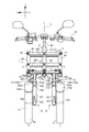
- FIG. 2 is an overall front view showing the three-wheeled vehicle 1 with the vehicle body cover 22 removed.
- the down frame 212 and the like are omitted.
- the three-wheel vehicle 1 includes a handle 23, a steering shaft 60, a head pipe 211, a pair of left and right front wheels 3, a first shock absorber 33, a first rotation prevention mechanism 340, a second shock absorber 35, a second rotation prevention mechanism 360, and a link mechanism. 5, an operation force transmission mechanism 6 and a deformation suppression mechanism 7 are provided.
- the front wheel 3 includes a first front wheel 31 and a second front wheel 32 arranged side by side in the left-right direction of the body frame 21.
- the first front wheel 31 as an example of the right front wheel is disposed on the right side with respect to the center in the vehicle width direction.
- a first front fender 223 a is disposed above the first front wheel 31.
- the second front wheel 32 as an example of the left front wheel is disposed on the left side with respect to the center in the vehicle width direction.
- a second front fender 223b is disposed above the second front wheel 32.
- the second front wheel 32 is disposed symmetrically with the first front wheel 31 in the left-right direction of the body frame 21.
- the “left-right direction of the body frame 21” refers to a direction orthogonal to the axial direction of the head pipe 211 in a front view of the three-wheeled vehicle 1.
- the first shock absorber 33 as an example of the right shock absorber supports the first front wheel 31 in the lower part and cushions the displacement of the body frame 21 in the vertical direction of the first front wheel 31 with respect to the upper part.
- the first shock absorber 33 includes a first shock absorber 330 and a first rotation prevention mechanism 340.
- the “vertical direction of the body frame 21” refers to a direction along the axial direction of the head pipe 211 in the front view of the three-wheeled vehicle 1.
- the second shock absorber 35 as an example of the left shock absorber supports the second front wheel 32 at the lower part and cushions the displacement of the body frame 21 in the vertical direction of the second front wheel 32 with respect to the upper part.
- the second shock absorber 35 includes a second shock absorber 350 and a second rotation prevention mechanism 360.
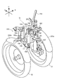
- FIG. 3 is a left side view showing the relationship between the second front wheel 32 and the second shock absorber 35.
- the second shock absorber 350 includes a second support member 321.
- the second support member 321 includes a second second outer cylinder 322, a second support shaft 323, and a second inner cylinder 326. A part of the second inner cylinder 326 is inserted on the inner peripheral side of the second outer cylinder 322.
- the second inner cylinder 326 is disposed above the second outer cylinder 322.
- the second inner cylinder 326 is movable relative to the second outer cylinder 322 in the direction in which the second outer cylinder 322 extends.
- the second shock absorber 350 is a so-called telescopic shock absorber.
- the second rotation prevention mechanism 360 prevents the second outer cylinder 322 from rotating with respect to the second inner cylinder 326.
- the second rotation prevention mechanism 360 includes a second guide 325, a second rotation prevention rod 361, and a second bracket 327.
- the second guide 325 guides the moving direction of the second rotation prevention rod 361.
- the second guide 325 includes a second guide cylinder 325b.
- a second anti-rotation rod 361 is inserted on the inner peripheral side of the second guide cylinder 325b.
- the second rotation preventing rod 361 can move relative to the second guide cylinder 325b.
- the second rotation prevention rod 361 prevents the second front wheel 32 from rotating relative to the second inner cylinder 326.
- the second rotation preventing rod 361 is disposed in parallel with the second shock absorber 350.
- the upper end of the second rotation prevention rod 361 and the upper end of the second inner cylinder 326 are fixed to the second bracket 327. As a result, the second rotation prevention rod 361 cannot move relative to the second inner
- the second front wheel 32 is supported by the second support member 321.
- the second front wheel 32 is connected to the lower part of the second support member 321.
- the second support shaft 323 is provided at the lower end of the second outer cylinder 322 and supports the second front wheel 32.
- the second guide 325 includes a second plate 325a.
- the second plate 325a extends to above the second front fender 223b.
- the second front wheel 32 can rotate around the second central axis Y and change its direction.
- the second central axis Y intersects the second plate 325a and the second connection point 325c.
- the first shock absorber 330 includes a first support member 331.
- the first support member 331 includes a first outer cylinder 332, a first support shaft 334, and a first inner cylinder 336.
- the first shock absorber 330 has the same configuration as the second shock absorber 350 described with reference to FIG. That is, a part of the first inner cylinder 336 is inserted on the inner peripheral side of the first outer cylinder 332.
- the first inner cylinder 336 is disposed above the first outer cylinder 332.
- the first inner cylinder 336 is movable relative to the first outer cylinder 332 in the direction in which the first outer cylinder 332 extends.
- the first shock absorber 330 is a so-called telescopic shock absorber.
- the first rotation prevention mechanism 340 prevents the first outer cylinder 332 from rotating with respect to the first inner cylinder 336.
- the first rotation prevention mechanism 340 has the same configuration as the second rotation prevention mechanism 360 described with reference to FIG. That is, the first rotation prevention mechanism 34 includes a first guide 333, a first rotation prevention rod 341, and a first bracket 335.
- the first guide 333 guides the moving direction of the first rotation prevention rod 341.
- the first guide 333 includes a first guide cylinder 333b.
- a first rotation preventing rod 341 is inserted on the inner peripheral side of the first guide cylinder 333b. The first rotation prevention rod 341 can be moved relative to the first guide cylinder 333b.
- the first rotation prevention rod 341 prevents the first front wheel 31 from rotating relative to the first inner cylinder 336.
- the first rotation preventing rod 341 is disposed in parallel with the first shock absorber 330.
- the upper ends of the first rotation preventing rod 341 and the first inner cylinder 336 are fixed to the first bracket 335. As a result, the first rotation prevention rod 341 cannot move relative to the first inner cylinder 336.
- the first front wheel 31 is supported by the first support member 331.
- the first front wheel 31 is connected to the lower part of the first support member 331.
- the first support shaft 334 is provided at the lower end of the first outer cylinder 332 and supports the first front wheel 31.
- the first guide 333 includes a first plate 333a.
- the first plate 333a extends to above the first front fender 223a.
- the first front wheel 31 can rotate around the first central axis X and change its direction.
- the first central axis X intersects the first plate 333a and the first connection point 333c.
- the link mechanism 5 is disposed below the handle 23.
- the link mechanism 5 is disposed above the first front wheel 31 and the second front wheel 32.
- the link mechanism 5 is connected to the head pipe 211.
- the link mechanism 5 includes a first cross member 51 (an example of an upper cross member), a second cross member 52 (an example of a lower cross member), a first side member 53 (an example of a right side rod), and a second side member 54. (An example of a left side rod).
- the first cross member 51 includes a pair of plate-like members 512.
- the first cross member 51 extends in the left-right direction of the body frame 21.
- the pair of plate-like members 512 sandwich the head pipe 211 in the front-rear direction of the body frame 21.
- the “front-rear direction of the body frame 21” refers to a direction that coincides with the front-rear direction of the three-wheeled vehicle 1.
- “extending in the left-right direction of the body frame 21” includes extending to the left-right direction of the body frame 21, and tilting closer to the left-right direction than the up-down direction and the front-rear direction of the body frame 21. It refers to extending at.
- the intermediate portion of the first cross member 51 is supported by the vehicle body frame 21 (head pipe 211) by the support portion A.
- the intermediate portion of the first cross member 51 is supported by the body frame 21 so as to be rotatable about a rotation axis (an example of an upper axis) extending in the front-rear direction of the body frame 21 in the support portion A. Even when the steering shaft 60 rotates with the rotation of the handle 23, the first cross member 51 does not rotate around the rotation axis of the steering shaft 60.
- extending in the front-rear direction of the body frame 21 includes extending obliquely with respect to the front-rear direction of the body frame 21, and tilting closer to the front-rear direction than the up-down direction and the left-right direction of the body frame. It refers to extending at.
- the right end portion of the first cross member 51 is connected to the upper portion of the first side member 53 by a connection portion B.
- the upper portion of the first side member 53 is supported by the right end portion of the first cross member 51 so as to be rotatable around a rotation axis extending in the front-rear direction of the body frame 21 at the connection portion B.
- the left end portion of the first cross member 51 is connected to the upper portion of the second side member 54 by the connection portion C.
- the upper part of the second side member 54 is supported by the left end portion of the first cross member 51 so as to be rotatable around the rotation axis extending in the front-rear direction of the body frame 21 at the connection portion C.
- the second cross member 52 includes a pair of plate-like members 522.
- the second cross member 52 extends in the left-right direction of the body frame 21.
- the pair of plate-like members 522 sandwich the head pipe 211 in the front-rear direction of the body frame 21.
- the second cross member 52 is disposed below the first cross member 51 and above the first shock absorber 33 and the second shock absorber 35 in the upright state of the vehicle body frame 21.
- the intermediate portion of the second cross member 52 is supported by the body frame 21 (head pipe 211) by the support portion D.
- the intermediate portion of the second cross member 52 is supported by the body frame 21 so as to be rotatable about a rotation axis (an example of a lower axis) extending in the front-rear direction of the body frame 21 in the support portion D.
- a rotation axis extending in the front-rear direction of the body frame 21 in the support portion D is parallel to a rotation axis extending in the front-rear direction of the body frame 21 in the support portion A.
- the right end portion of the second cross member 52 is connected to the lower portion of the first side member 53 by a connecting portion E.
- the lower portion of the first side member 53 is supported by the right end portion of the second cross member 52 so as to be rotatable around the rotation axis extending in the front-rear direction of the body frame 21 at the connection portion E.
- the left end portion of the second cross member 52 is connected to the lower portion of the second side member 54 by the connecting portion F.
- the lower part of the second side member 54 is supported by the left end portion of the second cross member 52 so as to be rotatable around the rotation axis extending in the front-rear direction of the body frame 21 at the connection portion F.
- first cross member 51 and the second cross member 52 include a pair of front and rear plate-like members extending in the left-right direction, but the first cross member 51 and the second cross member 52 are A configuration including a member extending rightward from the head pipe 211 and a member extending leftward from the head pipe 211 may be employed.
- the first side member 53 is disposed on the right side of the head pipe 211.
- the first side member 53 extends in a direction substantially parallel to the direction in which the head pipe 211 and the steering shaft 60 extend.
- the first side member 53 is disposed above the first front wheel 31 and the first shock absorber 33.
- the first side member 53 supports the upper part of the first shock absorber 33 so as to be rotatable about a first central axis X (an example of a right axis).
- the second side member 54 is disposed on the left side of the head pipe 211.
- the second side member 54 extends in a direction substantially parallel to the direction in which the head pipe 211 and the steering shaft 60 extend.
- the second side member 54 is disposed above the second front wheel 32 and the second shock absorber 35.
- the second side member 54 supports the upper portion of the second shock absorber 35 so as to be rotatable about the second central axis Y (an example of the left axis).
- the steering shaft 60 is supported by the vehicle body frame 21 between the first side member 53 and the second side member 54 in the left-right direction of the vehicle body frame 21.
- the upper end portion of the steering shaft 60 is provided above the rotational axis of the support portion D of the second cross member 52 in the vertical direction of the body frame 21.
- the steering shaft 60 is rotatable about an intermediate axis Z extending in the vertical direction of the vehicle body frame 21 (head pipe 211).
- “extending in the vertical direction of the body frame 21” includes extending while tilting with respect to the vertical direction of the vehicle body frame 21, and tilting closer to the vertical direction than the longitudinal direction and the horizontal direction of the body frame 21. It refers to extending at.
- FIG. 5 is a front view showing a state in which the vehicle body frame 21 is inclined leftward by an angle T.
- An upper portion of the vehicle body frame 21 is indicated by an arrow UF.
- the upper UF of the vehicle body frame 21 and the vertical upper U are coincident.
- the upper UF and the vertical upper U of the body frame 21 are different.
- the link mechanism 5 When the body frame 21 is tilted in the left-right direction, the link mechanism 5 is deformed.
- the body frame 21 head pipe 211
- the first cross member 51 and the second cross member 52 rotate with respect to the head pipe 211, the first side member 53, and the second side member 54.
- the extending direction of the first cross member 51 and the second cross member 52 is substantially parallel in a front view.
- the left end portion of the first cross member 51 moves to the left rather than the left end portion of the second cross member 52.
- the 2nd side member 54 inclines to the left from the attitude
- the extending direction of the second side member 54 is substantially parallel to the extending direction of the head pipe 211 in a front view.
- the first side member 53 is also inclined leftward from the posture in the upright state.
- the extending direction of the first side member 53 is parallel to the extending direction of the head pipe 211 in a front view.
- the body frame 21 tilts to the right from the posture in the upright state. Accordingly, the first cross member 51 and the second cross member 52 rotate with respect to the head pipe 211, the first side member 53, and the second side member 54. At this time, the extending direction of the first cross member 51 and the second cross member 52 is substantially parallel in a front view. As the head pipe 211 tilts to the right, the left end of the first cross member 51 moves to the right from the left end of the second cross member 52. Thereby, the 2nd side member 54 inclines to the right from the attitude
- the extending direction of the second side member 54 is substantially parallel to the extending direction of the head pipe 211 in a front view. Similar to the second side member 54, the first side member 53 is also inclined rightward from the posture in the upright state. The extending direction of the first side member 53 is parallel to the extending direction of the head pipe 211 in a front view. With the deformation of the link mechanism 5 as described above, the first front wheel 31 is displaced above the body frame 21 relative to the second front wheel 32, and the three-wheeled vehicle 1 is allowed to tilt rightward.
- the operation force transmission mechanism 6 as an example of the rotation transmission mechanism transmits the rotation of the steering shaft 60 according to the operation of the handle 23 to the first shock absorber 33 and the second shock absorber 35, and the first shock absorber 33 and the second shock absorber 33.
- the shock absorber 35 is rotated about the first central axis X and the second central axis Y, respectively.
- a part of the operating force transmission mechanism 6 is disposed below the second cross member 52.
- the operating force transmission mechanism 6 is disposed above the first front wheel 31 and the second front wheel 32.
- the lower end of the first side member 53 is connected to the first bracket 335.
- the first bracket 335 is attached to the first side member 53 so as to be rotatable about the first central axis X.
- the operating force transmission mechanism 6 connects the lower end portion of the steering shaft 60 and the first bracket 335.
- the operating force transmission mechanism 6 transmits the rotation of the steering shaft 60 accompanying the rotation operation of the handle 23 to the first bracket 335.
- the first bracket 335 rotates about the first central axis X with respect to the first side member 53.
- the first side member 53 does not rotate relative to the vehicle body frame 21 even when the handle 23 is rotated.
- the lower end of the second side member 54 is connected to the second bracket 327.
- the second bracket 327 is attached to the second side member 54 so as to be rotatable about the second central axis Y.
- the operating force transmission mechanism 6 connects the lower end portion of the steering shaft 60 and the second bracket 327.
- the operating force transmission mechanism 6 transmits the rotation of the steering shaft 60 accompanying the rotation operation of the handle 23 to the second bracket 327.
- the second bracket 327 rotates about the second central axis Y with respect to the second side member 54.
- the second side member 54 does not rotate relative to the vehicle body frame 21 even when the handle 23 is rotated.
- FIG. 6 is an enlarged front view showing the operating force transmission mechanism 6.
- the operating force transmission mechanism 6 includes a steering shaft 60, a first transmission plate 61, a second transmission plate 62, a third transmission plate 63, a first transmission member 67, a first bracket 335, and a second bracket 327.
- the first transmission plate 61 is connected to the lower end portion of the steering shaft 60.
- the first transmission plate 61 cannot rotate with respect to the steering shaft 60.
- the steering shaft 60 rotates with respect to the head pipe 211.
- the first transmission plate 61 rotates.
- the second transmission plate 62 is fixed to the first bracket 335 of the first shock absorber 33, and is rotatable with the first bracket 335 with respect to the first side member 53.
- the second transmission plate 62 is located below the first bracket 335.
- the third transmission plate 63 is arranged symmetrically with the second transmission plate 62 with the first transmission plate 61 as the center in the front view.
- the third transmission plate 63 is fixed to the second bracket 327 of the second shock absorber 35 and is rotatable with the second bracket 327 with respect to the second side member 54.
- the third transmission plate 63 is located below the second bracket 327.
- a portion fixed to the first shock absorber 33 and rotatable together with the first shock absorber 33 is a part of the first shock absorber 33. Therefore, the second transmission plate 62 of the operating force transmission mechanism 6 is also a part of the first shock absorber 33. Similarly, a portion fixed to the second shock absorber 35 and rotatable with the second shock absorber 35 is a part of the second shock absorber 35. Therefore, the third transmission plate 63 of the operating force transmission mechanism 6 is also a part of the second shock absorber 35.
- the first transmission member 67 transmits the operating force transmitted from the steering shaft 60 to the first bracket 335 and the second bracket 327.
- the first transmission member 67 extends in the left-right direction of the body frame 21. A detailed configuration for transmitting the operating force from the steering shaft 60 to the first bracket 335 and the second bracket 327 will be described later.
- FIG. 7 is a schematic plan view showing the configuration of the operating force transmission mechanism 6.
- the operating force transmission mechanism 6 is viewed from above, and the structures of the link mechanism 5 and the bracket are all omitted.
- a two-dot chain line indicates a state in which the steering shaft 60 is rotated in the direction of arrow A.
- the operating force transmission mechanism 6 further includes a first joint 64, a second joint 65, and a third joint 66.
- the front part of the first transmission plate 61 is narrower than the rear part of the first transmission plate 61.
- a first joint 64 is disposed at the front portion of the first transmission plate 61.
- the width of the front part of the second transmission plate 62 is narrower than the width of the rear part of the second transmission plate 62.
- a second joint 65 is disposed at the front portion of the second transmission plate 62.
- the second transmission plate 62 is disposed on the right side of the first transmission plate 61.
- the width of the front part of the third transmission plate 63 is narrower than the width of the rear part of the third transmission plate 63.
- a third joint 66 is disposed at the front portion of the third transmission plate 63.
- the third transmission plate 63 is disposed on the left side of the first transmission plate 61.
- the first joint 64 includes a first bearing 641, a first shaft 642, and a first front rod 643.
- the first shaft 642 is rotatable relative to the first bearing 641.
- the first bearing 641 supports the first shaft 642.
- the first bearing 641 is supported by the first transmission plate 61.
- the first transmission plate 61 includes a first support hole 641 b that supports the first shaft 642.
- the first shaft 642 is fitted into the first support hole 641b.
- the first bearing 641 is fixed to the first shaft 642.
- the first shaft 642 is disposed at the front end of the first transmission plate 61.
- the first front rod 643 extends forward from the first bearing 641.
- the first front rod 643 is relatively rotatable in the left-right direction around the first shaft 642 as the first bearing 641 rotates with respect to the first transmission plate 61.
- the first front rod 643 is fixed to the first bearing 641.
- the second joint 65 includes a second bearing 651, a second shaft 652, and a second front rod 653.
- the second bearing 651 has the same configuration as the first bearing 641.
- the second shaft 652 has the same configuration as the first shaft 642.
- the second front rod 653 has the same configuration as the first front rod 643.
- the third joint 66 includes a third bearing 661, a third shaft 662, and a third front rod 663.
- the third bearing 661 has the same configuration as the first bearing 641.
- the third shaft 662 has the same configuration as the first shaft 642.
- the third front rod 663 has the same configuration as the first front rod 643.
- the first transmission member 67 includes a first ring 671, a second ring 672, and a third ring 673.
- a first front rod 643 is inserted into the first ring 671.
- the first ring 671 is provided at the center in the left-right direction of the first transmission member 67.
- the second ring 672 is disposed on the right side of the first ring 671.
- a second front rod 653 is inserted into the second ring 672.
- the third ring 673 is disposed on the left side of the first ring 671.
- a third front rod 663 is inserted into the third ring 673.
- FIG. 8 is a plan view of the second front wheel 32 and the second bracket 327.
- a two-dot chain line in FIG. 8 shows a state in which the second front wheel 32 has turned.
- the second front fender 223b is not shown.
- the second bracket 327 is connected to the second side member 54 as described above.
- a third transmission plate 63 is attached to the second bracket 327.
- the first transmission plate 61 rotates as the steering shaft 60 rotates.
- the first joint 64 moves to the right rear as the first transmission plate 61 rotates.
- the first shaft 642 rotates with respect to the first bearing 641, and the first transmission member 67 is moved to the right rear while maintaining the posture of the first transmission member 67.
- the second front rod 653 and the third front rod 663 move to the right rear.
- the second bearing 651 and the third bearing 661 move to the right rear.
- the second transmission plate 62 and the third transmission plate 63 are centered on the first side member 53 and the second side member 54, respectively. , Rotate in the direction of arrow A. Thereby, it will be in the state shown with the dashed-two dotted line in FIG.
- the rotation center of the second transmission plate 62 coincides with the first central axis X.
- the rotation center of the third transmission plate 63 coincides with the second central axis Y.
- the second bracket 327 rotates in the direction of arrow B in FIG.
- the second front wheel 32 rotates in the direction of arrow C in FIG.
- the front wheel 32 rotates rightward about the second central axis Y.
- the front wheel 32 is in a state indicated by a two-dot chain line in FIG.
- the first front wheel 31 rotates to the right about the first central axis X in the same manner as the second front wheel 32. In this way, by operating the handle 23 in the left-right direction of the body frame 21, the first front wheel 31 and the second front wheel 32 rotate in the left-right direction of the body frame 21.
- the deformation suppressing mechanism 7 as an example of the resistance force changing mechanism suppresses deformation of the link mechanism 5. Specifically, the resistance force applied to the rotation operation of the first cross member 51 and the second cross member 52 with respect to the vehicle body frame 21 is changed. As shown in FIG. 2, the deformation suppression mechanism 7 includes a first connection member 11, a second connection member 12, and a suppression mechanism 75.
- the first connecting member 11 is attached to the first plate 333a.
- the first connection member 11 is attached to a first connection point 333 c where the first plate 333 a intersects the first central axis X.
- the 1st connection member 11 does not need to be arrange
- the first connection member 11 is attached to the upper surface of the first plate 333a. The first connection member 11 extends from the first plate 333 a toward the head pipe 211.
- the second connecting member 12 is attached to the second plate 325a.
- the second connection member 12 is attached to a second connection point 325c where the second plate 325a intersects the second central axis Y.
- the 2nd connection member 12 does not need to be arrange
- the second connection member 12 is attached to the upper surface of the second plate 325a.
- the second connecting member 12 extends from the second plate 325a toward the head pipe 211.
- the suppression mechanism 75 suppresses the movement of the first connecting member 11 with respect to the head pipe 211.
- the suppression mechanism 75 suppresses the movement of the second connection member 12 with respect to the head pipe 211.
- FIG. 9 is a left side view showing a part of the suppression mechanism 75.
- the suppression mechanism 75 includes a caliper 72, a lever 73, and a connection mechanism 74.
- the calipers 72 are arranged on the right and left sides of the head pipe 211, respectively. However, in FIG. 9, only the left caliper 72 is shown. Since the first connecting member 11 has the same configuration as the second connecting member 12, the description thereof is omitted. FIG. 9 shows only the left second connection member 12.
- the second connection member 12 includes a rotation support portion 12a and a pole 12b.
- the rotation support part 12a supports one end of the pole 12b.
- the rotation support portion 12a supports the pole 12b so as to be rotatable in the direction of an arrow D around a rotation axis extending in the left-right direction of the body frame 21.
- the pole 12b extends upward from the second plate 325a toward the rear.
- the rear end of the pole 12b is a free end.
- a part of the pole 12 b is supported by a caliper 72.
- the pole 12b and the caliper 72 can be relatively displaced.
- FIG. 10 is a perspective view showing a part of the suppression mechanism 75.
- the rotation support part 12a not only supports the pole 12b so as to be rotatable in the direction of the arrow D, but also supports the pole 12b so as to be rotatable in the direction of the arrow V.
- An arrow V indicates a direction of rotation about a rotation axis (second central axis Y) extending in the vertical direction of the body frame 21.
- the caliper 72 is disposed outward of the down frame 212 in the vehicle width direction.
- the caliper 72 has a support member 72a.
- the support member 72a is connected to the vehicle body frame 21.
- the lever 73 is disposed behind the down frame 212.
- the lever 73 is used when operating the caliper 72.
- the lever 73 is connected to the connection mechanism 74.
- the lever 73 is attached to the vehicle body cover 22.
- connection mechanism 74 connects the lever 73 and the caliper 72.
- the connection mechanism 74 operates the caliper 72 so as to grip the pole 12b of the second connection member 12 when the lever 73 is operated.
- the caliper 72 When the caliper 72 grips the pole 12b, the resistance against the relative displacement between the second connecting member 12 and the caliper 72 increases. Thereby, the relative movement of the 2nd connection member 12 and the caliper 72 is suppressed. Similarly, the relative movement of the first connecting member 11 and the caliper 72 is suppressed. That is, the caliper 72 suppresses the movement of the first connecting member 11 and the second connecting member 12 with respect to the head pipe 211 when the lever 73 is operated.
- the occupant When the inclination of the three-wheeled vehicle 1 (that is, deformation of the link mechanism 5) is to be suppressed (for example, during parking), the occupant operates the lever 73.
- the lever 73 When the lever 73 is operated, the caliper 72 suppresses the movement of the first connecting member 11 and the second connecting member 12 with respect to the head pipe 211. Thereby, the movement to the up-down direction of the vehicle body frame 21 of the 1st front wheel 31 and the 2nd front wheel 32 is suppressed, and a deformation
- the deformation suppressing mechanism 7 includes the first connecting member 11 and the second connecting member 12 (an example of the first part) that can be relatively displaced, and the caliper 72 (an example of the second part), Resistance to these relative displacements can be changed.
- the first connecting member 11 and the second connecting member 12 are provided with rotation support portions 11 a and 12 a (an example of the first support portion) supported by the first shock absorber 33 and the second shock absorber 35, respectively. )have.
- the caliper 72 has a support member 72a (an example of a second support portion) supported by the vehicle body frame 21 (down frame 212). As shown in FIG.
- the position where the rotation support portion 11 a is supported is below the second cross member 52 in the vertical direction of the vehicle body frame 21 and in the horizontal direction of the vehicle body frame 21.
- the intermediate axis Z is closer to the first central axis X.
- the position at which the rotation support portion 12 a is supported is lower than the second cross member 52 in the vertical direction of the vehicle body frame 21 and more than the intermediate axis Z in the horizontal direction of the vehicle body frame 21. 2 Close to the central axis Y.
- the first shock absorber 33 and the second shock absorber 35 are positioned below the second cross member 52 in the upright state of the vehicle body frame 21. Further, a space for avoiding mutual interference is formed between the first shock absorber 33 and the second shock absorber 35, the link mechanism 5 and the vehicle body frame 21.
- the rotation support portions 11a and 12a of the deformation suppressing mechanism 7 are supported by the first shock absorber 33 and the second shock absorber 35 below the second cross member 52 in the vertical direction of the vehicle body frame 21 in the upright state of the vehicle body frame 21.
- the movable range of the deformation suppressing mechanism 7 can be made smaller than the movable range of the link mechanism 5.
- the space formed between the first shock absorber 33 and the second shock absorber 35, the link mechanism 5 and the vehicle body frame 21 can also be used as a movable range of the deformation suppressing mechanism 7.
- the link mechanism 5 and the vehicle body frame 21 as the movable range of the deformation suppressing mechanism 7, the above-described relative relationship is achieved. It can suppress that the movable range of the deformation
- the movable range of the deformation suppressing mechanism 7 can be made smaller than the movable range of the link mechanism 5. Moreover, even if the 1st buffer 33 and the 2nd buffer 35 rotate, it can suppress that the movable range of the deformation
- the support member 72a of the caliper 72 is disposed above the rotation support portions 11a and 12a when the body frame 21 is upright.
- the deformation suppression mechanism 7 includes the rotation support portions 11a and 12a at the lower portion thereof, and the support member 72a at the upper portion thereof, and changes the resistance force against the relative vertical movement of the rotation support portions 11a and 12a and the support member 72a. It can be configured as possible. Thereby, size reduction and simplification of the deformation
- the support member 72 a is disposed closer to the intermediate axis Z than the first central axis X and the second central axis Y in the upright state of the body frame 21.
- the rotation support portions 11 a and 12 a and the support member 72 a move up and down relatively in the vertical direction of the vehicle body frame 21 in conjunction with the inclination of the vehicle body frame 21. Further, in conjunction with the inclination of the body frame 21, the body frame 21 also relatively moves left and right in the left and right direction. Therefore, the deformation suppressing mechanism 7 can use at least one of the vertical movement and the horizontal movement.
- the space formed between the link mechanism 5 and the vehicle body frame 21 and the first shock absorber 33 and the second shock absorber 35 can be used as a movable range of the deformation restrain mechanism 7. Miniaturization and simplification are possible.
- the movable range of the deformation suppressing mechanism 7 can be reduced. Therefore, even if a function for suppressing the operation of the link mechanism 5 is provided, an increase in the size of the structure around the steering shaft 60 disposed above the two front wheels 31 and 32 can be suppressed.
- first connection member 11 and the second connection member 12 are each provided with an axis (first line) extending in the vertical direction of the vehicle body frame 21 with respect to the first shock absorber 33 and the second shock absorber 35.
- first line axis
- first line center axis X and second center axis Y.
- the rotation axes of the first shock absorber 33 and the second shock absorber 35 and the rotation axes of the first connection member 11 and the second connection member 12 both extend in the vertical direction of the vehicle body frame 21. Therefore, it can suppress that the movable range of the 1st connection member 11 and the 2nd connection member 12 accompanying rotation of the 1st buffer 33 and the 2nd buffer 35 becomes large. Therefore, even if a function for suppressing the operation of the link mechanism 5 is provided, an increase in the size of the structure around the steering shaft 60 disposed above the two front wheels 31 and 32 can be suppressed.
- the first connection member 11 includes a rotation support portion 11 a (an example of a right first support portion) supported by a first support portion 331 disposed at a lower portion of the first shock absorber 33.
- the second connection member 12 includes a rotation support portion 12a (an example of a left first support portion) that is supported by a second support member 321 disposed below the second shock absorber 35.
- the position at which the rotation support portion 11a is supported is lower than the second cross member 52 in the vertical direction of the vehicle body frame 21 and in the horizontal direction of the vehicle body frame 21 with respect to the intermediate axis Z in the upright state of the vehicle body frame 21. 1 Close to the central axis X.
- the position at which the rotation support portion 12a is supported is lower than the second cross member 52 in the vertical direction of the vehicle body frame 21 in the upright state of the vehicle body frame 21 and higher than the intermediate axis Z in the horizontal direction of the vehicle body frame 21. 2 Close to the central axis Y.
- the movement of the first front wheel 31 and the second front wheel 32 relative to the head pipe 211 is suppressed in a state where the vertical positions of the body frame 21 of the first front wheel 31 and the second front wheel 32 are different. Therefore, the vehicle can be parked in a state where the three-wheeled vehicle 1 is tilted or in a state where one front wheel 3 is mounted on the step.
- the rotation support portion 11a is disposed at the first connection point 333c.
- the rotation support portion 12a is disposed at the second connection point 325c.
- FIG. 11 is a perspective view showing a part of the three-wheeled vehicle 10.
- illustration of the steering wheel and the steering shaft is omitted.
- Elements having the same or similar configurations as those of the first embodiment are not shown or given the same numbers, and repeated descriptions are omitted.
- the three-wheeled vehicle 10 according to the second embodiment includes a deformation suppressing mechanism 8.
- the deformation suppressing mechanism 8 is different from the deformation suppressing mechanism 7 according to the first embodiment in the configuration for suppressing the deformation of the link mechanism 5.
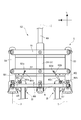
- FIG. 12 is an enlarged view of a part of the three-wheeled vehicle 10 as viewed from the rear.
- the deformation suppression mechanism 8 includes a first connection member 13, a second connection member 14, and a suppression mechanism 76.
- the first support member 331 of the first shock absorber 33 includes a first guide 333.
- the first guide 333 includes a first support plate 131.
- the first support plate 131 is located above the first front wheel 31.
- the first support plate 131 extends from the first guide 333 to the right side of the vehicle body frame 21.
- the first support plate 131 includes a first fixing member 131a.
- the first fixing member 131a is disposed at a first connection point 131c where the first central axis X and the first support plate 131 intersect.
- the first connection member 13 includes a first support arm 132, a first connection arm 133, and a first attachment member 134.
- the first support arm 132 extends in a direction intersecting the first support plate 131.
- the first support arm 132 is fixed to the first fixing member 131a.
- the upper end portion of the first support arm 132 rotatably supports the first connection arm 133.
- the first support arm 132 is rotatable about the first central axis X at a first connection point 131c where the first central axis X and the first support plate 131 intersect. That is, the first support arm 132 and the first connection arm 133 can be relatively displaced.
- the first connection arm 133 is connected to the first bracket 335 supported by the first side member 53 of the link mechanism 5.
- the first connection arm 133 extends from the upper end of the first support arm 132 toward the left rear.
- the first attachment member 134 is fixed to the vehicle body frame 21.
- the first attachment member 134 is provided with a first through hole 134 a extending in the left-right direction of the body frame 21.
- a part of the first connection arm 133 is disposed in the first through hole 134a.
- the first connection arm 133 is rotatable about a rotation axis extending in the left-right direction of the body frame 21 at a portion supported by the first attachment member 134.
- the second support member 321 of the second shock absorber 35 includes a second guide 325.
- the second guide 325 includes a second support plate 141.
- the second support plate 141 is located above the second front wheel 32.
- the second support plate 141 extends from the second guide 325 to the left of the vehicle body frame 21.
- the second support plate 141 includes a second fixing member 141a.
- the second fixing member 141a is disposed at a second connection point 141c where the second central axis Y and the second support plate 141 intersect.
- the second connection member 14 includes a second support arm 142, a second connection arm 143, and a second attachment member 144.
- the second support arm 142 extends in a direction intersecting the second support plate 141.
- the second support arm 142 is fixed to the second fixing member 141a.
- the upper end portion of the second support arm 142 rotatably supports the second connection arm 143.
- the second support arm 142 is rotatable about the second central axis Y at a second connection point 141c where the second central axis Y and the second support plate 141 intersect. That is, the second support arm 142 and the second connection arm 143 can be relatively displaced.
- the second connection arm 143 is connected to the second bracket 327 supported by the second side member 54 of the link mechanism 5.
- the second connection arm 143 extends from the upper end of the second support arm 142 toward the right rear.
- the second attachment member 144 is fixed to the vehicle body frame 21.
- the second mounting member 144 is provided with a second through hole 144a extending in the left-right direction of the body frame 21.
- a part of the second connection arm 143 is disposed in the second through hole 144a.
- the second connection arm 143 is rotatable around a rotation axis extending in the left-right direction of the body frame 21 at a portion supported by the second attachment member 144.
- the suppression mechanism 76 includes a disk 81 and a caliper 82.
- the disk 81 is attached to the right end portion of the second connection arm 143.
- the disk 81 cannot rotate with respect to the second connection arm 143. Therefore, when the second connection arm 143 rotates about the axis extending in the left-right direction of the body frame 21, the disk 81 rotates about the connection portion with the second connection arm 143.
- the disk 81 has a fan-shaped plate shape.
- the caliper 82 is attached to the left end of the first connection arm 133.
- the caliper 82 cannot rotate with respect to the first connection arm 133. Therefore, when the first connection arm 133 rotates about the rotation axis extending in the left-right direction of the body frame 21, the caliper 82 rotates about the connection portion with the first connection arm 133.
- a groove is formed in the caliper 82.
- a disc 81 is inserted into the groove of the caliper 82.
- a pad (not shown) is disposed in the groove of the caliper 82.
- a mechanism (not shown) for pressing the pad against the disk 81 is attached to the caliper 82.
- the caliper 82 can suppress the rotation of the disk 81 relative to the caliper 82 by pressing the pad against the disk 81.
- the caliper 82 suppresses the rotation of the disk 81 when a switch 23a (see FIG. 1) attached to the handle 23 is operated.
- the first support portion 331 moves upward.
- the first support plate 131 and the first support arm 132 move upward.
- the first support arm 132 moves upward, the right end portion of the first connection arm 133 is lifted upward. Since the first connection arm 133 is supported by the first mounting member 134 so as to be relatively rotatable, the first connection arm 133 rotates about a rotation center axis extending in the left-right direction of the vehicle body frame 21. As the first connection arm 133 rotates, the caliper 82 rotates in the direction of arrow E.
- the second support member 321 moves upward.
- the second support plate 141 and the second support arm 142 move upward.
- the second support arm 142 moves upward, the left end portion of the second connection arm 143 is lifted upward. Since the second connection arm 143 is supported by the second mounting member 144 so as to be relatively rotatable, the second connection arm 143 rotates about the rotation center axis extending in the left-right direction of the body frame 21. As the second connection arm 143 rotates, the disk 81 rotates in the direction of arrow E.
- the caliper 82 and the disk 81 rotate relative to each other.
- the switch 23 a When the switch 23 a is operated, the pad provided in the groove of the caliper 82 is pressed against the disk 81. In this way, the rotation of the disk 81 with respect to the caliper 82 is suppressed.
- the resistance against the relative displacement of the first support arm 132 and the first connection arm 133 increases.
- the resistance to the relative displacement of the second support arm 142 and the second connection arm 143 increases.
- first front wheel 31 and the second front wheel 32 in the vertical direction of the body frame 21 is restricted.
- first connection arm 133 and the second connection arm 143 are connected to the first side member 53 and the second side member 54, respectively, the vehicle body frame 21 of the first side member 53 and the second side member 54 is provided.
- the displacement in the vertical direction is also suppressed, and the deformation of the link mechanism 5 is suppressed.
- the deformation suppressing mechanism 8 includes the first connecting member 13 and the second connecting member 14.
- the first connection member 13 includes a first support arm 132 (an example of a first part) and a first connection arm 133 (an example of a second part) that are relatively displaceable, and are resistant to these relative displacements. Can be changed by the suppression mechanism 76.
- the first support arm 132 is supported by the first shock absorber 33 in a first fixing member 131a (an example of a first support portion).
- the first connection arm 133 is supported by the vehicle body frame 21 in a first attachment member 134 (an example of a second support portion).
- the second connection member 14 includes a second support arm 142 (an example of the first part) and a second connection arm 143 (an example of the second part) that are relatively displaceable, and are resistant to these relative displacements. Can be changed by the suppression mechanism 76.
- the second support arm 142 is supported by the second shock absorber 35 in the second fixing member 141a (an example of the first support portion).
- the second connection arm 143 is supported by the vehicle body frame 21 in a second attachment member 144 (an example of a second support portion). In the upright state of the vehicle body frame 21, the position where the first fixing member 131 a is supported is lower than the second cross member 52 in the vertical direction of the vehicle body frame 21 and more than the intermediate axis Z in the horizontal direction of the vehicle body frame 21.
- the first shock absorber 33 and the second shock absorber 35 are positioned below the second cross member 52 in the upright state of the vehicle body frame 21. Further, a space for avoiding mutual interference is formed between the first shock absorber 33 and the second shock absorber 35, the link mechanism 5 and the vehicle body frame 21.
- the first fixing member 131a and the second fixing member 141a of the deformation suppressing mechanism 8 are located below the second cross member 52 in the vertical direction of the body frame 21 and the second shock absorber 33 and the second fixing member 131a.
- the movable range of the deformation suppressing mechanism 8 can be made smaller than the movable range of the link mechanism 5.
- the space formed between the first shock absorber 33 and the second shock absorber 35, the link mechanism 5 and the vehicle body frame 21 can also be used as the movable range of the deformation suppression mechanism 8.
- transformation suppression mechanism 8 is supported by the 1st buffer 33 and the 2nd buffer 35, there exists a possibility that the movable range of the deformation
- the first fixing member 131a and the second fixing member 141a are supported by the first shock absorber 33 and the second shock absorber 35 at positions closer to the first central axis X and the second central axis Y than the intermediate axis Z, respectively. As a result, it is possible to suppress an increase in the movable range of the deformation suppressing mechanism 8 associated with the relative rotation described above.
- the link mechanism 5 and the vehicle body frame 21 as the movable range of the deformation suppressing mechanism 8, the above-described relative relationship is achieved. It can suppress that the movable range of the deformation
- the movable range of the deformation suppressing mechanism 8 can be made smaller than the movable range of the link mechanism 5. Moreover, even if the 1st buffer 33 and the 2nd buffer 35 rotate, it can suppress that the movable range of the deformation
- the first mounting member 134 and the second mounting member 144 are disposed above the first fixing member 131a and the second fixing member 141a in the upright state of the vehicle body frame 21.
- the deformation suppressing mechanism 8 includes a first fixing member 131a and a second fixing member 141a in the lower part thereof, and includes a first mounting member 134 and a second mounting member 144 in the upper part thereof, and the first fixing member 131a and the second fixing member 144a.
- the resistance force with respect to the fixed member 141a and the relative vertical movement of the first attachment member 134 and the second attachment member 144 can be changed.
- transformation suppression mechanism 8 size reduction and simplification of the deformation
- transformation suppression mechanism 8 are attained.
- the movable range of the deformation suppressing mechanism 8 can be further reduced. Therefore, even if the function of suppressing the operation of the link mechanism 5 is provided, it is possible to suppress an increase in the size of the structure around the steering shaft 60 disposed above the two front wheels 31 and 32.
- the first mounting member 134 and the second mounting member 144 are disposed closer to the intermediate axis Z than the first central axis X and the second central axis Y in the upright state of the vehicle body frame 21.
- the first fixing member 131 a and the second fixing member 141 a, and the first mounting member 134 and the second mounting member 144 are interlocked with the inclination of the vehicle body frame 21, and the vertical direction of the vehicle body frame 21. Moves up and down relatively. Further, in conjunction with the inclination of the body frame 21, the body frame 21 also relatively moves left and right in the left and right direction. Therefore, the deformation suppressing mechanism 8 can use at least one of the vertical movement and the horizontal movement.
- the space formed between the link mechanism 5 and the vehicle body frame 21 and the first shock absorber 33 and the second shock absorber 35 can be used as a movable range of the deformation suppression mechanism 8. Miniaturization and simplification are possible.
- the movable range of the deformation suppressing mechanism 8 can be reduced. Therefore, even if a function for suppressing the operation of the link mechanism 5 is provided, an increase in the size of the structure around the steering shaft 60 disposed above the two front wheels 31 and 32 can be suppressed.
- the first support arm 132 and the second support arm 142 are axes (first central axis X and second central axis Y) extending in the vertical direction of the vehicle body frame 21 with respect to the first shock absorber 33 and the second shock absorber 35, respectively. It can be rotated around the center.
- the rotation axes of the first shock absorber 33 and the second shock absorber 35 and the rotation axes of the first support arm 132 and the second support arm 142 both extend in the vertical direction of the vehicle body frame 21. Therefore, it is possible to suppress an increase in the movable range of the first support arm 132 and the second support arm 142 due to the rotation of the first shock absorber 33 and the second shock absorber 35. Therefore, even if a function for suppressing the operation of the link mechanism 5 is provided, an increase in the size of the structure around the steering shaft 60 disposed above the two front wheels 31 and 32 can be suppressed.
- the first support arm 132 includes a first fixing member 131a (an example of a right first support portion) that is supported by a first support portion 331 disposed below the first shock absorber 33.
- the second support arm 142 includes a second fixing member 141 a (an example of a left first support portion) that is supported by a second support member 321 that is disposed below the second shock absorber 35.
- the position at which the first fixing member 131a is supported is lower than the second cross member 52 in the vertical direction of the vehicle body frame 21 in the upright state of the vehicle body frame 21 and from the intermediate axis Z in the horizontal direction of the vehicle body frame 21. Close to the first central axis X.
- the position where the second fixing member 141a is supported is lower than the second cross member 52 in the vertical direction of the vehicle body frame 21 and in the left-right direction of the vehicle body frame 21 relative to the intermediate axis Z in the upright state of the vehicle body frame 21. Close to the second central axis Y.
- the first front wheel 31 and the second front wheel 32 are moved relative to the head pipe 211 with the first front wheel 31 and the second front wheel 32 in different positions in the vertical direction of the body frame 21. Since it can suppress, it can park in the state which inclined the three-wheeled vehicle 10, and the state which got on the one front wheel 3 on the level
- the deformation suppression mechanism 8 since a part of the deformation suppression mechanism 8 is disposed below the second cross member 52, all of the deformation suppression mechanism 8 is disposed above the second cross member 52.
- the center of gravity of the three-wheeled vehicle 10 can be lowered compared to the case where the three-wheeled vehicle 10 is used.
- one end of the first support arm 132 is disposed at the first connection point 131c.
- One end of the second support arm 142 is disposed at the second connection point 141c. Therefore, even if the first front wheel 31 rotates about the first central axis X and the second front wheel 32 rotates about the second central axis Y, the first connection point 131c and the second connection point 141c The position with respect to the head pipe 211 is not changed. Accordingly, the rotation of the first front wheel 31 and the second front wheel 32 is not hindered by the first support arm 132 and the second support arm 142.
- the suppression mechanism 76 includes a disk 81 and a caliper 82.
- the suppression mechanism 76 may be replaced with the configuration described below.
- FIG. 13 is a view showing a suppression mechanism 85 according to a modification of the second embodiment.
- the suppression mechanism 85 includes a first disk 851, a second disk 852, and a caliper 853.
- the first disk 851 has a fan-shaped plate shape.
- the first disk 851 is fixed to the left end portion of the first connection arm 133. Therefore, the first disk 851 rotates as the first connection arm 133 rotates.
- the second disk 852 has a fan-shaped plate shape.
- the second disk 852 is fixed to the right end portion of the second connection arm 143. Therefore, as the second connection arm 143 rotates, the second disk 852 rotates.
- the second disk 852 is disposed on the left side of the first disk 851.
- the caliper 853 is fixed to the vehicle body frame 21.
- the caliper 853 includes a groove that can accommodate a part of the first disk 851 and a part of the second disk 852.
- the caliper 853 includes a pad (not shown) in the groove. The caliper 853 suppresses the rotation of the first disk 851 and the second disk 852 by pressing the pads individually on the first disk 851 and the second disk 852 in the groove.
- rotation of the first disk 851 and the second disk 852 is suppressed by one caliper 853.
- the first caliper that suppresses the rotation of the first disk 851 and the second caliper that suppresses the rotation of the second disk 852 may be included.
- FIG. 14 is a front view showing the three-wheeled vehicle 100 with the vehicle body cover 22 removed. Elements having the same or similar configurations as those of the first embodiment are not illustrated or assigned the same reference numerals, and repeated descriptions are omitted.
- the three-wheeled vehicle 100 according to the third embodiment includes a deformation suppressing mechanism 9.
- the deformation suppression mechanism 9 is different from the deformation suppression mechanism 7 according to the first embodiment in the configuration for suppressing the deformation of the link mechanism 5.
- FIG. 15 is an enlarged front view showing a partial configuration of the deformation suppressing mechanism 9.
- the deformation suppression mechanism 9 includes a first connection portion 15, a second connection portion 16, a suppression mechanism 29, and a fixing mechanism 77.
- the first connection portion 15 is attached to the first plate 333a of the first shock absorber 33.
- the first connection part 15 includes a first support cylinder 145 and a first cylinder support part 146.
- the first support cylinder 145 extends in the left-right direction of the body frame 21.
- the first support cylinder 145 is supported by the first cylinder support portion 146.
- the first tube support portion 146 includes a rotation shaft extending in the front-rear direction of the vehicle body frame 21.
- the first cylinder support portion 146 supports the first support cylinder 145 so as to be rotatable in the direction of the arrow M around the rotation axis.
- the first plate 333a supports the first tube support portion 146 so as to be rotatable in the direction of the arrow Q about the first central axis X.
- the second connection portion 16 is fixed to the second plate 325a of the second shock absorber 35.
- the second connection part 16 includes a second support cylinder 151 and a second cylinder support part 152.
- the second support cylinder 151 extends in the left-right direction of the body frame 21.
- the second support cylinder 151 is supported by the second cylinder support portion 152.
- the second cylinder support portion 152 includes a rotation shaft extending in the front-rear direction of the vehicle body frame 21.
- the second cylinder support portion 152 supports the second support cylinder 151 so as to be rotatable in the direction of arrow G about the rotation axis.
- the second plate 325a supports the second cylinder support 152 so as to be rotatable in the direction of the arrow S about the second central axis Y.
- the suppression mechanism 29 includes a first suppression pole 161, a second suppression pole 162, a rotation center shaft 163, a support pole 164, a disk 165, and a first caliper 166.
- the first suppression pole 161 is inserted into the first support cylinder 145.
- the first suppression pole 161 extends in the left-right direction of the body frame 21.
- the first suppression pole 161 is located above the first front wheel 31.
- the first suppression pole 161 is disposed behind the first shock absorber 330.
- the first suppression pole 161 is located below the link mechanism 5.
- the second suppression pole 162 is inserted into the second support cylinder 151.
- the second suppression pole 162 is disposed on the left side of the first suppression pole 161.
- the second suppression pole 162 extends in the left-right direction of the body frame 21.
- the second suppression pole 162 is located above the second front wheel 32.
- the second suppression pole 162 is disposed behind the second shock absorber 350.
- the second suppression pole 162 is located below the link mechanism 5.
- the rotation center shaft 163 supports the left end portion of the first suppression pole 161 and the right end portion of the second suppression pole 162.
- the rotation center shaft 163 extends in the front-rear direction of the body frame 21.
- FIG. 16 is a perspective view schematically showing a part of the suppression mechanism 29 in an enlarged manner.
- a rear end portion of the rotation center shaft 163 is connected to the support pole 164.
- the rotation center shaft 163 is rotatable relative to the support pole 164 around a rotation shaft extending in the front-rear direction of the body frame 21.
- the support pole 164 extends in the vertical direction of the body frame 21.
- the disk 165 is fixed to the first suppression pole 161 and the second suppression pole 162.
- the disk 165 has a semicircular shape around the rotation center axis 163.
- the disk 165 is located above the first suppression pole 161 and the second suppression pole 162.
- the first suppression pole 161, the second suppression pole 162, and the disk 165 rotate integrally around the rotation center axis 163.
- the first caliper 166 is fixed to the support pole 164.
- the first caliper 166 is located above the rotation center axis 163.
- the switch 23 a (see FIG. 1) provided on the handle 23 is operated, the first caliper 166 suppresses the rotation of the disk 165 by pressing a pad (not shown) against the disk 165.
- first connecting portion 15 and the second connecting portion 16 can be displaced relative to the first caliper 166. Further, the first caliper 166 can change the resistance against relative displacement.
- the fixing mechanism 77 fixes the suppression mechanism 17 to the vehicle body frame 21.
- the fixing mechanism 77 includes a second caliper 91.
- the second caliper 91 is disposed above the first caliper 166.
- the second caliper 91 is attached to the vehicle body frame 21 (head pipe 211) via the first transmission plate 61.
- the second caliper 91 is configured such that the support pole 164 is movable in the vertical direction of the body frame 21.
- the switch 23a provided on the handle 23 is operated, the second caliper 91 grips the support pole 164 and restricts the vertical movement. That is, the first caliper 166 can be displaced relative to the second caliper 91.
- the second caliper 91 can change the resistance against relative displacement.
- the support pole 164 is relatively displaced with respect to the second caliper 91 according to the operation of the first shock absorber 33 and the second shock absorber 35, so that the second restraining pole 162 is positioned above the first restraining pole 161.
- the restraining mechanism 29 in the state of being allowed is allowed to move in the vertical direction with respect to the head pipe 211.
- the support pole 164 is relatively displaced with respect to the second caliper 91 according to the operation of the first shock absorber 33 and the second shock absorber 35, so that the first restraining pole 161 is positioned above the second restraining pole 162.
- the restraining mechanism 29 in the state of being allowed is allowed to move in the vertical direction with respect to the head pipe 211.
- the first caliper 166 suppresses the rotation of the disk 165 with respect to the first caliper 166.
- position change of the 1st suppression pole 161 and the 2nd suppression pole 162 is suppressed, the relative movement with respect to the 1st caliper 166 of the 1st connection part 15 and the 2nd connection part 16 is suppressed. Therefore, the relative movement of the first front wheel 31 and the second front wheel 32 in the vertical direction of the body frame 21 is suppressed, and deformation of the link mechanism 5 is suppressed.
- the switch 23a by operating the switch 23a, the vertical movement of the support pole 164 with respect to the second caliper 91 is suppressed, and the relative displacement of the first caliper 166 with respect to the second caliper 91 is suppressed. Accordingly, the first front wheel 31 and the second front wheel 32 in a state in which the relative displacement is suppressed are suppressed from being displaced in the vertical direction of the vehicle body frame 21 according to the operations of the first shock absorber 33 and the second shock absorber 35.
- the suppression of the displacement of the first caliper 166 with respect to the second caliper 91 may be performed independently of the suppression of the displacement of the disk 165 with respect to the first caliper 166. *
- the deformation suppressing mechanism 9 includes the first and second suppressing poles 161 and 162 (an example of the first part) and the first caliper 166 (an example of the second part) that are relatively displaceable.
- the resistance force to these relative displacements can be changed.
- the first suppression pole 161 and the second suppression pole 162 are supported by the first shock absorber 33 and the second shock absorber 35 via the first connection portion 15 and the second connection portion 16 (an example of a first support portion), respectively.
- the first caliper 166 is supported by the vehicle body frame 21 (head pipe 211) via a fixing mechanism 77 (an example of a second support portion).
- the position where the first connection portion 15 is supported is lower than the second cross member 52 in the vertical direction of the vehicle body frame 21 and more than the intermediate axis Z in the horizontal direction of the vehicle body frame 21. Close to the first central axis X.
- the position where the second connecting portion 16 is supported is lower than the second cross member 52 in the vertical direction of the vehicle body frame 21 and more than the intermediate axis Z in the horizontal direction of the vehicle body frame 21. Close to the second central axis Y.
- the first shock absorber 33 and the second shock absorber 35 are positioned below the second cross member 52 in the upright state of the vehicle body frame 21. Further, a space for avoiding mutual interference is formed between the first shock absorber 33 and the second shock absorber 35, the link mechanism 5 and the vehicle body frame 21.
- the first connecting portion 15 and the second connecting portion 16 of the deformation suppressing mechanism 9 are disposed below the second cross member 52 in the vertical direction of the vehicle body frame 21 in the upright direction of the vehicle body frame 21, and the first shock absorber 33 and the second connection portion 16.
- the movable range of the deformation suppressing mechanism 9 can be made smaller than the movable range of the link mechanism 5.
- the space formed between the first shock absorber 33 and the second shock absorber 35, the link mechanism 5 and the vehicle body frame 21 can also be used as a movable range of the deformation suppressing mechanism 9.
- transformation suppression mechanism 9 when supported by the 1st buffer 33 and the 2nd buffer 35, there exists a possibility that the movable range of the deformation
- the first connection portion 15 and the second connection portion 16 are supported by the first shock absorber 33 and the second shock absorber 35 at positions closer to the first central axis X and the second central axis Y than the intermediate axis Z, respectively.
- the movable range of the deformation suppressing mechanism 9 can be made smaller than the movable range of the link mechanism 5. Moreover, even if the 1st buffer 33 and the 2nd buffer 35 rotate, it can suppress that the movable range of the deformation
- the fixing mechanism 77 is disposed above the first connection portion 15 and the second connection portion 16 in the upright state of the vehicle body frame 21.
- the deformation suppressing mechanism 9 includes a first connection portion 15 and a second connection portion 16 at a lower portion thereof, and a fixing mechanism 77 at an upper portion thereof.
- the resistance force to the relative vertical movement of the can be configured to be changeable.
- transformation suppression mechanism 9 are attained.
- the movable range of the deformation suppressing mechanism 9 can be further reduced. Therefore, even if a function for suppressing the operation of the link mechanism 5 is provided, an increase in the size of the structure around the steering shaft 60 disposed above the two front wheels 31 and 32 can be suppressed.
- the fixing mechanism 77 is disposed closer to the intermediate axis Z than the first central axis X and the second central axis Y in the upright state of the body frame 21.
- the first connection portion 15, the second connection portion 16, and the fixing mechanism 77 move up and down relatively in the vertical direction of the body frame 21 in conjunction with the inclination of the body frame 21. Further, in conjunction with the inclination of the body frame 21, the body frame 21 also relatively moves left and right in the left and right direction. Therefore, the deformation suppressing mechanism 9 can use at least one of the vertical movement and the horizontal movement.
- the space formed between the link mechanism 5 and the vehicle body frame 21 and the first shock absorber 33 and the second shock absorber 35 can be used as a movable range of the deformation restrain mechanism 9. Miniaturization and simplification are possible. Further, the movable range of the deformation suppressing mechanism 9 can be reduced. Therefore, even if a function for suppressing the operation of the link mechanism 5 is provided, an increase in the size of the structure around the steering shaft 60 disposed above the two front wheels 31 and 32 can be suppressed.
- the first suppression pole 161 and the second suppression pole 162 are axes (first central axis X and second central axis Y) extending in the vertical direction of the vehicle body frame 21 with respect to the first shock absorber 33 and the second shock absorber 35, respectively. It can be rotated around the center.
- the rotation axes of the first shock absorber 33 and the second shock absorber 35 and the rotation axes of the first restraining pole 161 and the second restraining pole 162 both extend in the vertical direction of the vehicle body frame 21. Therefore, it is possible to suppress an increase in the movable range of the first suppression pole 161 and the second suppression pole 162 due to the rotation of the first shock absorber 33 and the second shock absorber 35. Therefore, even if a function for suppressing the operation of the link mechanism 5 is provided, an increase in the size of the structure around the steering shaft 60 disposed above the two front wheels 31 and 32 can be suppressed.
- the first suppression pole 161 has a first connection portion 15 (an example of a right first support portion) supported by a first support member 331 disposed at the lower portion of the first shock absorber 33.
- the second suppression pole 162 has a second connection portion 16 (an example of a left first support portion) supported by a second support member 321 disposed at the lower portion of the second shock absorber 35.
- the position at which the first connection portion 15 is supported is lower than the second cross member 52 in the vertical direction of the vehicle body frame 21 in the upright state of the vehicle body frame 21 and more than the intermediate axis Z in the horizontal direction of the vehicle body frame 21. Close to the first central axis X.
- the position at which the second connecting portion 16 is supported is lower than the second cross member 52 in the vertical direction of the vehicle body frame 21 in the upright state of the vehicle body frame 21 and more than the intermediate axis Z in the horizontal direction of the vehicle body frame 21. Close to the second central axis Y.
- the vertical movement suppression of the support pole 164 by the second caliper 91 can be performed independently of the rotation suppression of the disk 165 by the first caliper 166.
- the first front wheel 31 and the second front wheel 32 are allowed to move up and down as a unit while the relative movement between the first front wheel 31 and the second front wheel 32 is suppressed. Therefore, the occupant can easily move the three-wheeled vehicle 100 while the body frame 21 is inclined from the upright state.
- a part of the deformation suppression mechanism 9 is disposed below the second cross member 52. For this reason, the center of gravity of the three-wheeled vehicle 100 can be lowered as compared with the case where all the configurations of the deformation suppressing mechanism 9 are disposed above the second cross member 52.
- FIG. 18 is a perspective view showing the three-wheeled vehicle 101 with the vehicle body cover 22 removed. Elements having the same or similar configurations as those of the first embodiment are not illustrated or assigned the same reference numerals, and repeated descriptions are omitted.
- the three-wheeled vehicle 101 according to the fourth embodiment includes a deformation suppressing mechanism 78.
- the deformation suppression mechanism 78 is different from the deformation suppression mechanism 7 according to the first embodiment in the configuration for suppressing the deformation of the link mechanism 5.
- the deformation suppression mechanism 78 includes a first connection member 17, a second connection member 18, a suppression mechanism 19, and a fixing mechanism 30.
- the first connection member 17 is fixed to the first outer cylinder 332 of the first shock absorber 330.
- the first connection member 17 is a semicircular plate-shaped member.
- the first connection member 17 extends from the first outer cylinder 332 toward the second front wheel 32.
- the second connecting member 18 is fixed to the second outer cylinder 322 of the second shock absorber 350.
- the second connection member 18 is a semicircular plate-like member.
- the second connecting member 18 extends from the second outer cylinder 322 toward the first front wheel 31.
- the suppression mechanism 19 is disposed below the second cross member 52 and between the first connection member 17 and the second connection member 18.
- the fixing mechanism 30 is disposed above the suppression mechanism 19.
- the fixing mechanism 30 is supported by the head pipe 211.
- FIG. 19 is a perspective view showing the lower part of the three-wheeled vehicle 101.
- the suppression mechanism 19 includes a first roller unit 191, a second roller unit 192, a roller support shaft 193, a roller support plate 194, a first coil spring 195, a second coil spring 196, and a rotation mechanism 20.
- the first roller unit 191 includes a pair of rollers arranged side by side in the vertical direction of the body frame 21.
- the first roller unit 191 is supported by a roller support plate 194.
- the second roller unit 192 includes a pair of rollers arranged side by side in the vertical direction of the body frame 21.
- the second roller unit 192 is supported by the roller support plate 194.
- the second roller unit 192 is disposed symmetrically with the first roller unit 191 with respect to the roller support shaft 193.
- the roller support shaft 193 supports the roller support plate 194.
- the roller support shaft 193 is located below the head pipe 211.
- the roller support shaft 193 extends in the same direction as the head pipe 211 extends (that is, the vertical direction of the body frame 21).
- a fixing mechanism 30 is disposed above the roller support shaft 193 (see FIG. 18).
- the fixing mechanism 30 has the same configuration as the fixing mechanism 77 provided in the three-wheeled vehicle 100 according to the third embodiment. That is, the fixing mechanism 30 includes a caliper that supports the roller support shaft 193 so as to be displaceable in the vertical direction of the vehicle body frame 21. For example, when the switch 23a (see FIG. 1) is operated, the caliper grips the roller support shaft 193 and suppresses the displacement of the vehicle body frame 21 in the vertical direction.
- the roller support plate 194 supports the first roller unit 191 and the second roller unit 192.
- the roller support plate 194 includes a thin plate 194a and a support tube 194b.
- the thin plate 194a extends upward from the support cylinder 194b.
- the support cylinder 194 b covers a part of the roller support shaft 193.
- the support cylinder 194b is rotatable with respect to the roller support shaft 193.
- the roller support plate 194 can rotate in the direction of arrow H around the roller support shaft 193.
- the roller support shaft 193 extends below the lower end of the roller support plate 194.
- the first coil spring 195 is wound around the roller support shaft 193.
- the first coil spring 195 is disposed above the support cylinder 194b.
- the lower end of the first coil spring 195 is in contact with the upper end of the support cylinder 194b.
- the second coil spring 196 is wound around the roller support shaft 193.
- the second coil spring 196 is disposed below the support cylinder 194b.
- the upper end of the second coil spring 196 is in contact with the lower end of the roller support plate 194.
- the rotating mechanism 20 moves the thin plate 194a of the roller support plate 194 backward.
- the rotation mechanism 20 rotates the roller support plate 194 around the roller support shaft 193.
- the rotation mechanism 20 rotates the roller support plate 194 in the arrow H direction.
- the rotation mechanism 20 is located above the roller support plate 194.
- the rotation mechanism 20 includes a lever 201, a lever support member 202, and a connecting rod 203.
- the lever 201 extends in the vertical direction of the body frame 21.
- the lower end of the lever 201 is connected to the connecting rod 203.
- the lever support member 202 supports the lever 201 from behind.
- the lever support member 202 is disposed in front of the head pipe 211.
- the lever support member 202 supports the lever 201 rotatably.
- the lever 201 is rotatable in the direction of the arrow J around the rotation axis extending in the left-right direction of the body frame 21.
- the connecting rod 203 connects the lever 201 and the thin plate 194a.
- the rear end of the connecting rod 203 is connected to the lower end of the lever 201.
- the connecting rod 203 is rotatable with respect to the lever 201.
- the front end of the connecting rod 203 is connected to the upper end of the thin plate 194a.
- the connecting rod 203 is rotatable with respect to the thin plate 194a.
- FIG. 20 shows the lower part of the three-wheeled vehicle 101 when the upper part of the lever 201 is tilted forward from the state shown in FIG.
- the lever 201 rotates around the rotation axis extending in the left-right direction of the vehicle body frame 21 at the point where the lever 201 is supported by the lever support member 202.
- the lever 201 rotates, the lower portion of the lever 201 moves backward.
- the connecting rod 203 moves the thin plate 194a backward.
- the roller support plate 194 rotates around the roller support shaft 193 in the direction of arrow H.
- the first connection member 17 is sandwiched between the pair of rollers included in the first roller unit 191, and the second connection member 18 is sandwiched between the pair of rollers included in the second roller unit 192. . That is, the first connection member 17, the second connection member 18, and the suppression mechanism 19 are relatively displaceable. In addition, the resistance of the relative displacement can be changed (switching between a state with a resistance force and a state without a resistance force) by the operation of the suppression mechanism 19.
- the relative displacement of the first front wheel 31 and the second front wheel 32 in the vertical direction of the body frame 21 is suppressed. Accordingly, the vehicle body of the first side member 53 connected to the first front wheel 31 via the first shock absorber 33 and the second side member 54 connected to the second front wheel 32 via the second shock absorber 35.
- the relative displacement of the frame 21 in the vertical direction is suppressed. Thereby, a deformation
- the first front wheel 31 and the second front wheel 32 can move up and down together.
- the support cylinder 194 b of the roller support plate 194 is sandwiched between the first coil spring 195 and the second coil spring 196. Therefore, even when an impact is applied to the first front wheel 31 and the second front wheel 32 when the three-wheeled vehicle 101 is moved in a state in which the first front wheel 31 and the second front wheel 32 are not relatively movable, the first coil spring The impact is absorbed by 195 and the second coil spring 196.
- the switch 23a by operating the switch 23a to operate the fixing mechanism 30, the vertical movement of the roller support shaft 193 is suppressed, and the integral vertical movement of the first front wheel 31 and the second front wheel 32 is also suppressed.
- the deformation suppressing mechanism 78 includes the relatively displaceable first connecting member 17 and second connecting member 18 (an example of the first part), and the suppressing mechanism 19 (an example of the second part).
- the resistance force to these relative displacements can be changed.
- the first connection member 17 and the second connection member 18 are supported by the first shock absorber 33 and the second shock absorber 35 via a first outer cylinder 332 and a second outer cylinder 322 (an example of a first support portion), respectively.
- the suppression mechanism 19 is supported by the vehicle body frame 21 (head pipe 211) via a fixing mechanism 30 (an example of a second support portion).
- the position where the first outer cylinder 332 is supported is lower than the second cross member 52 in the vertical direction of the vehicle body frame 21 and more than the intermediate axis Z in the horizontal direction of the vehicle body frame 21. Close to the first central axis X.
- the position where the second outer cylinder 322 is supported is lower than the second cross member 52 in the vertical direction of the vehicle body frame 21 and more than the intermediate axis Z in the horizontal direction of the vehicle body frame 21. Close to the second central axis Y.
- the first shock absorber 33 and the second shock absorber 35 are positioned below the second cross member 52 in the upright state of the vehicle body frame 21. Further, a space for avoiding mutual interference is formed between the first shock absorber 33 and the second shock absorber 35, the link mechanism 5 and the vehicle body frame 21.
- the first outer cylinder 332 and the second outer cylinder 322 of the deformation suppressing mechanism 78 are located below the second cross member 52 in the vertical direction of the body frame 21 and the second shock absorber 33 and the second outer cylinder 322.
- the movable range of the deformation suppressing mechanism 78 can be made smaller than the movable range of the link mechanism 5.
- the space formed between the first shock absorber 33 and the second shock absorber 35, the link mechanism 5 and the vehicle body frame 21 can also be used as a movable range of the deformation suppressing mechanism 78.
- transformation suppression mechanism 78 is supported by the 1st buffer 33 and the 2nd buffer 35, there exists a possibility that the movable range of the deformation
- the first outer cylinder 332 and the second outer cylinder 322 are supported by the first shock absorber 33 and the second shock absorber 35 at positions closer to the first central axis X and the second central axis Y than the intermediate axis Z, respectively. By doing this, it is possible to suppress an increase in the movable range of the deformation suppression mechanism 78 associated with the relative rotation described above.
- the link mechanism 5 and the vehicle body frame 21 as the movable range of the deformation suppressing mechanism 78, the above-described relative relationship is achieved. It can suppress that the movable range of the deformation
- the movable range of the deformation suppressing mechanism 78 can be made smaller than the movable range of the link mechanism 5. Moreover, even if the 1st buffer 33 and the 2nd buffer 35 rotate, it can suppress that the movable range of the deformation
- the fixing mechanism 30 is disposed above the first outer cylinder 332 and the second outer cylinder 322 when the body frame 21 is upright.
- the deformation suppressing mechanism 78 includes a first outer cylinder 332 and a second outer cylinder 322 at a lower portion thereof, and a fixing mechanism 30 at an upper portion thereof.
- the resistance force to the relative vertical movement of the can be configured to be changeable.
- the deformation suppressing mechanism 78 can be reduced in size and simplified.
- the movable range of the deformation suppression mechanism 78 can be further reduced. Therefore, even if a function for suppressing the operation of the link mechanism 5 is provided, an increase in the size of the structure around the steering shaft 60 disposed above the two front wheels 31 and 32 can be suppressed.
- the fixing mechanism 30 is disposed closer to the intermediate axis Z than the first central axis X and the second central axis Y in the upright state of the body frame 21.
- the deformation suppressing mechanism 78 can use at least one of the vertical movement and the horizontal movement.
- the space formed between the link mechanism 5 and the vehicle body frame 21 and the first shock absorber 33 and the second shock absorber 35 can be used as a movable range of the deformation restrain mechanism 78, and Miniaturization and simplification are possible.
- the movable range of the deformation suppression mechanism 78 can be reduced. Therefore, even if a function for suppressing the operation of the link mechanism 5 is provided, an increase in the size of the structure around the steering shaft 60 disposed above the two front wheels 31 and 32 can be suppressed.
- the first connecting member 17 and the second connecting member 18 are axes (first central axis X and second central axis Y) extending in the vertical direction of the vehicle body frame 21 with respect to the first shock absorber 33 and the second shock absorber 35, respectively. It can be rotated around the center. Further, the suppression mechanism 19 is rotatable about an axis (center axis Z) extending in the vertical direction of the body frame 21.
- the rotation axis of the first shock absorber 33 and the second shock absorber 35, the rotation axis of the first connection member 17 and the second connection member 18, and the rotation axis of the suppression mechanism 19 are all in the body frame. 21 extends in the vertical direction. Therefore, it can suppress that the movable range of the 1st connection member 17 and the 2nd connection member 18 accompanying rotation of the 1st buffer 33 and the 2nd buffer 35 becomes large. In addition, the movable range of the suppression mechanism 19 can be reduced. Therefore, even if a function for suppressing the operation of the link mechanism 5 is provided, an increase in the size of the structure around the steering shaft 60 disposed above the two front wheels 31 and 32 can be suppressed.
- the first connection member 17 has a first outer cylinder 332 (an example of a right first support portion) supported by a first support portion 331 disposed at a lower portion of the first shock absorber 33.
- the second connection member 18 includes a second outer cylinder 322 (an example of a left first support portion) that is supported by a second support member 321 disposed below the second shock absorber 35.
- the position at which the first outer cylinder 332 is supported is lower than the second cross member 52 in the vertical direction of the vehicle body frame 21 in the upright state of the vehicle body frame 21 and more than the intermediate axis Z in the horizontal direction of the vehicle body frame 21. Close to the first central axis X.
- the position where the second outer cylinder 322 is supported is lower than the second cross member 52 in the vertical direction of the vehicle body frame 21 in the upright state of the vehicle body frame 21 and more than the intermediate axis Z in the horizontal direction of the vehicle body frame 21. Close to the second central axis Y.
- the vertical movement suppression of the roller support shaft 193 by the fixing mechanism 30 is performed independently of the relative displacement restriction of the first connection member 17 and the second connection member 18 by the suppression mechanism 19. Can do.
- the first front wheel 31 and the second front wheel 32 are allowed to move up and down as a unit while the relative movement between the first front wheel 31 and the second front wheel 32 is suppressed. Therefore, the occupant can easily move the three-wheeled vehicle 101 while keeping the body frame 21 from tilting from the upright state.
- a part of the deformation suppressing mechanism 78 is located below the second cross member 52. For this reason, the position of the center of gravity of the three-wheeled vehicle 101 can be lowered as compared with the case where all of the deformation suppression mechanisms 78 are disposed above the second cross member 52.
- the first connection member 17 is sandwiched between a pair of rollers provided in the first roller unit 191.
- the second connection member 18 is sandwiched between a pair of rollers provided in the second roller unit 192.
- the first connection member 17 and the second connection member 18 are, for example, a pair of plates arranged in the vertical direction of the body frame 21. May be configured to be sandwiched.
- the roller pair is caught even if the first connecting member 17 and the second connecting member 18 are not strictly positioned between the roller pair.
- the first connecting member 17 and the second connecting member 18 can be guided to a predetermined clamping position.
- FIG. 21 is an enlarged front view showing a part of the three-wheeled vehicle 102. Elements having the same or similar configurations as those of the first embodiment are not illustrated or assigned the same reference numerals, and repeated descriptions are omitted.
- the three-wheeled vehicle 102 includes a deformation suppressing mechanism 600.
- the deformation suppression mechanism 600 is different from the deformation suppression mechanism 7 according to the first embodiment in the configuration for suppressing the deformation of the link mechanism 5.
- the deformation suppressing mechanism 600 includes a first damper 601 and a second damper 602.
- the first damper 601 is an oil damper having a first cylinder 601a and a first rod 601b.
- the first rod 601b has a piston (not shown) that can slide in the first cylinder 601a.
- a lower end 601c of the first cylinder 601a is supported by the first bracket 335 of the first shock absorber 33.
- the lower end portion 601c of the first cylinder 601a is allowed to be three-dimensionally displaced with respect to the first bracket 335 by a ball joint or the like.
- the upper end 601d of the first rod 601b is supported by the second cross member 52 of the link mechanism 5.
- the upper end portion 601d of the first rod 601b is allowed to be three-dimensionally displaced with respect to the second cross member 52 by a ball joint or the like.
- the first cylinder 601a and the first rod 601b are relatively displaceable. For example, by operating the switch 23a (see FIG. 1), the flow state of the oil stored in the first cylinder 601a is limited, and the resistance force to the relative displacement between the first cylinder 601a and the first rod 601b is increased. it can.
- the second damper 602 is an oil damper having a second cylinder 602a and a second rod 602b.
- the second rod 602b has a piston (not shown) that can slide in the second cylinder 602a.
- the lower end 602c of the second cylinder 602a is supported by the second bracket 327 of the second shock absorber 35.
- the lower end portion 602c of the second cylinder 602a is allowed to be three-dimensionally displaced with respect to the second bracket 327 by a ball joint or the like.
- An upper end 602 d of the second rod 602 b is supported by the second cross member 52 of the link mechanism 5.
- the upper end portion 602d of the second rod 602b is allowed to be three-dimensionally displaced with respect to the second cross member 52 by a ball joint or the like.
- the second cylinder 602a and the second rod 602b are relatively displaceable. For example, by operating the switch 23a, the flow state of the oil stored in the second cylinder 602a is limited, and the resistance force to the relative displacement of the second cylinder 602a and the second rod 602b can be increased.
- the switch 23a by operating the switch 23a in the upright state of the vehicle body frame 21 (head pipe 211) shown in FIG. 21, expansion and contraction of the first damper 601 and the second damper 602 are suppressed. Therefore, the inclination of the head pipe 211 from the upright state to the left-right direction is suppressed, and the deformation of the link mechanism 5 is suppressed.
- the switch 23a may be operated in the state of the posture.
- the deformation suppressing mechanism 600 includes the first damper 601 and the second damper 602.
- the first damper 601 includes a relatively displaceable first cylinder 601a (an example of a first part) and a first rod 601b (an example of a second part), and resistance to these relative displacements can be changed. It is said that.
- a lower end portion 601c (an example of a first support portion) of the first cylinder 601a is supported by the first bracket 335 of the first shock absorber 33.
- An upper end portion 601 d (an example of a second support portion) of the first rod 601 b is supported by the second cross member 52 of the link mechanism 5.
- the second damper 602 includes a relatively displaceable second cylinder 602a (an example of the first part) and a second rod 602b (an example of the second part), and resistance to these relative displacements can be changed. It is said that.
- a lower end portion 602c (an example of a first support portion) of the second cylinder 602a is supported by the second bracket 327 of the second shock absorber 35.
- An upper end portion 602 d (an example of a second support portion) of the second rod 602 b is supported by the second cross member 52 of the link mechanism 5.
- the position at which the lower end portion 601 c of the first cylinder 601 a is supported is lower than the second cross member 52 in the vertical direction of the body frame 21, and in the horizontal direction of the body frame 21. It is closer to the first central axis X than Z.
- the position where the lower end portion 602 c of the second cylinder 602 a is supported is lower than the second cross member 52 in the vertical direction of the body frame 21, and the intermediate axis in the left-right direction of the body frame 21. It is closer to the second central axis Y than Z.
- the first shock absorber 33 and the second shock absorber 35 are positioned below the second cross member 52 in the upright state of the vehicle body frame 21. Further, a space for avoiding mutual interference is formed between the first shock absorber 33 and the second shock absorber 35, the link mechanism 5 and the vehicle body frame 21.
- the lower end 601c of the first cylinder 601a and the lower end 602c of the second cylinder 602a are lower in the vertical direction of the body frame 21 than the second cross member 52 in the upright state of the body frame 21.
- the movable range of the deformation suppressing mechanism 600 can be made smaller than the movable range of the link mechanism 5.
- the space formed between the first shock absorber 33 and the second shock absorber 35, the link mechanism 5 and the vehicle body frame 21 can also be used as a movable range of the deformation suppressing mechanism 600.
- the deformation suppressing mechanism 600 has a wide range of parts that can support the upper end 601d of the first rod 601b and the upper end 602d of the second rod 602b, and the degree of freedom in design is high. Therefore, the upper end portion 601d of the first rod 601b and the upper end portion 602d of the second rod 602b can be easily supported at a portion where the movable range can be reduced. Thereby, the movable range of the deformation
- transformation suppression mechanism 600 is supported by the 1st buffer 33 and the 2nd buffer 35, there exists a possibility that the movable range of the deformation
- the lower end 601c of the first cylinder 601a and the lower end 602c of the second cylinder 602a are closer to the first central axis X and the second central axis Y than the intermediate axis Z, respectively.
- the shock absorber 35 it is possible to suppress an increase in the movable range of the deformation suppressing mechanism 600 accompanying the relative rotation described above.
- the link mechanism 5 and the vehicle body frame 21 as the movable range of the deformation suppressing mechanism 600, the above-described relative relationship is achieved. An increase in the movable range of the deformation suppression mechanism 600 accompanying rotation can be suppressed.
- the movable range of the deformation suppressing mechanism 600 can be made smaller than the movable range of the link mechanism 5. Moreover, even if the 1st shock absorbing device 33 and the 2nd shock absorbing device 35 rotate, it can suppress that the movable range of the deformation
- the upper end 601d of the first rod 601b and the upper end 602d of the second rod 602b are disposed above the lower end 601c of the first cylinder 601a and the lower end 602c of the second cylinder 602a when the vehicle body frame 21 is upright. ing.
- the deformation suppressing mechanism 600 includes a lower end portion 601c of the first cylinder 601a and a lower end portion 602c of the second cylinder 602a at the lower portion, and an upper end portion 601d of the first rod 601b and an upper end portion of the second rod 602b at the upper portion thereof.
- the deformation suppressing mechanism 600 can be reduced in size and simplified.
- the movable range of the deformation suppressing mechanism 600 can be further reduced. Therefore, even if the function of suppressing the operation of the link mechanism 5 is provided, it is possible to suppress an increase in the size of the structure around the steering shaft 60 disposed above the two front wheels 31 and 32.
- the first mounting member 134 and the second mounting member 144 are disposed closer to the intermediate axis Z than the first central axis X and the second central axis Y in the upright state of the vehicle body frame 21.
- the deformation suppressing mechanism 600 can use at least one of the vertical movement and the horizontal movement.
- the space formed between the link mechanism 5 and the vehicle body frame 21 and the first shock absorber 33 and the second shock absorber 35 can be used as a movable range of the deformation suppression mechanism 600.
- the movable range of the deformation suppressing mechanism 600 can be reduced. Therefore, even if a function for suppressing the operation of the link mechanism 5 is provided, an increase in the size of the structure around the steering shaft 60 disposed above the two front wheels 31 and 32 can be suppressed.
- the first cylinder 601a and the second cylinder 602a are centered on axes (first central axis X and second central axis Y) extending in the vertical direction of the vehicle body frame 21 with respect to the first shock absorber 33 and the second shock absorber 35, respectively. Can be rotated.
- the rotation axes of the first shock absorber 33 and the second shock absorber 35 and the rotation axes of the first cylinder 601a and the second cylinder 602a both extend in the vertical direction of the vehicle body frame 21. Therefore, it can suppress that the movable range of the 1st cylinder 601a and the 2nd cylinder 602a accompanying the rotation of the 1st buffer 33 and the 2nd buffer 35 becomes large. Therefore, even if a function for suppressing the operation of the link mechanism 5 is provided, an increase in the size of the structure around the steering shaft 60 disposed above the two front wheels 31 and 32 can be suppressed.
- a lower end portion 601c of the first cylinder 601a and a lower end portion 602c of the second cylinder 602a are supported by a first bracket 335 and a second bracket 327 disposed on top of the first shock absorber 33 and the second shock absorber 35, respectively. .
- the lower end 601c of the first cylinder 601a and the lower end 602c of the second cylinder 602a are compared to the case where they are supported by the lower portions of the first shock absorber 33 and the second shock absorber 35.
- the dimension of the deformation suppressing mechanism 600 in the vertical direction of the frame 21 can be reduced. Therefore, the movable range of the deformation suppression mechanism 600 can be reduced. Therefore, even if a function for suppressing the operation of the link mechanism 5 is provided, an increase in the size of the structure around the steering shaft 60 disposed above the two front wheels 31 and 32 can be suppressed.
- FIG. 22 is an enlarged front view showing a part of the three-wheeled vehicle 103. Elements having the same or similar configurations as those of the first embodiment are not illustrated or assigned the same reference numerals, and repeated descriptions are omitted.
- the three-wheeled vehicle 103 includes a deformation suppression mechanism 700.
- the deformation suppression mechanism 700 is different from the deformation suppression mechanism 7 according to the first embodiment in the configuration for suppressing the deformation of the link mechanism 5.
- the deformation suppressing mechanism 700 includes a first damper 701 and a second damper 702.
- the first damper 701 is an oil damper having a first cylinder 701a and a first rod 701b.
- the first rod 701b has a piston (not shown) that can slide in the first cylinder 701a.
- a lower end 701c of the first cylinder 701a is supported by the second transmission plate 62 of the first shock absorber 33.
- the second transmission plate 62 also serves as a part of the operating force transmission mechanism 6.
- the lower end portion 701c of the first cylinder 701a is allowed to be three-dimensionally displaced with respect to the first bracket 335 by a ball joint or the like.
- the upper end 701d of the first rod 701b is supported by the second cross member 52 of the link mechanism 5.
- the upper end portion 701d of the first rod 701b is allowed to be three-dimensionally displaced with respect to the second cross member 52 by a ball joint or the like.
- the first cylinder 701a and the first rod 701b are relatively displaceable. For example, by operating the switch 23a, the flow state of the oil stored in the first cylinder 701a is limited, and the resistance force to the relative displacement of the first cylinder 701a and the first rod 701b can be increased.
- the second damper 702 is an oil damper having a second cylinder 702a and a second rod 702b.
- the second rod 702b has a piston (not shown) that can slide in the second cylinder 702a.
- a lower end portion 702c of the second cylinder 702a is supported by the third transmission plate 63 of the second shock absorber 35. As described above, the third transmission plate 63 also serves as a part of the operating force transmission mechanism 6.
- the lower end portion 702c of the second cylinder 702a is allowed to be three-dimensionally displaced with respect to the second bracket 327 by a ball joint or the like.
- An upper end 702d of the second rod 702b is supported by the second cross member 52 of the link mechanism 5.
- the upper end portion 702d of the second rod 702b is allowed to be three-dimensionally displaced with respect to the second cross member 52 by a ball joint or the like.
- the second cylinder 702a and the second rod 702b are relatively displaceable.
- the operation of the switch 23a restricts the flow state of the oil stored in the second cylinder 702a, and increases the resistance against the relative displacement of the second cylinder 702a and the second rod 702b. it can.
- the switch 23a by operating the switch 23a in the upright state of the vehicle body frame 21 (head pipe 211) shown in FIG. 21, expansion and contraction of the first damper 701 and the second damper 702 are suppressed. Therefore, the inclination of the head pipe 211 from the upright state to the left-right direction is suppressed, and the deformation of the link mechanism 5 is suppressed.
- the switch 23a may be operated in the state of the posture.
- the deformation suppressing mechanism 700 includes the first damper 701 and the second damper 702.
- the first damper 701 includes a relatively displaceable first cylinder 701a (an example of a first part) and a first rod 701b (an example of a second part), and the resistance force to these relative displacements can be changed. It is said that.
- a lower end portion 701c (an example of a first support portion) of the first cylinder 701a is supported by the second transmission plate 62 of the first shock absorber 33.
- An upper end portion 701 d (an example of a second support portion) of the first rod 701 b is supported by the second cross member 52 of the link mechanism 5.
- the second damper 702 includes a relatively displaceable second cylinder 702a (an example of the first part) and a second rod 702b (an example of the second part), and resistance to these relative displacements can be changed. It is said that.
- a lower end portion 702c (an example of a first support portion) of the second cylinder 702a is supported by the third transmission plate 63 of the second shock absorber 35.
- An upper end portion 702 d (an example of a second support portion) of the second rod 702 b is supported by the second cross member 52 of the link mechanism 5.
- the position at which the lower end 701 c of the first cylinder 701 a is supported is lower than the second cross member 52 in the vertical direction of the body frame 21, and the intermediate axis in the left-right direction of the body frame 21. It is closer to the first central axis X than Z.
- the position at which the lower end portion 702 c of the second cylinder 702 a is supported is lower than the second cross member 52 in the vertical direction of the body frame 21, and the intermediate axis in the left-right direction of the body frame 21. It is closer to the second central axis Y than Z.
- the first shock absorber 33 and the second shock absorber 35 are positioned below the second cross member 52 in the upright state of the vehicle body frame 21. Further, a space for avoiding mutual interference is formed between the first shock absorber 33 and the second shock absorber 35, the link mechanism 5 and the vehicle body frame 21.
- the lower end 701c of the first cylinder 701a and the lower end 702c of the second cylinder 702a are lower in the vertical direction of the body frame 21 than the second cross member 52 in the upright state of the body frame 21.
- the movable range of the deformation suppressing mechanism 700 can be made smaller than the movable range of the link mechanism 5.
- the space formed between the first shock absorber 33 and the second shock absorber 35, the link mechanism 5 and the vehicle body frame 21 can also be used as a movable range of the deformation suppressing mechanism 700.
- the deformation suppressing mechanism 700 has a wide range of portions that can support the upper end portion 701d of the first rod 701b and the upper end portion 702d of the second rod 702b, and the degree of freedom in design is high. Therefore, it becomes easy to support the upper end portion 701d of the first rod 701b and the upper end portion 702d of the second rod 702b at a portion where the movable range can be reduced. Thereby, the movable range of the deformation
- transformation suppression mechanism 700 is supported by the 1st buffer 33 and the 2nd buffer 35, there exists a possibility that the movable range of the deformation
- the lower end 701c of the first cylinder 701a and the lower end 702c of the second cylinder 702a are closer to the first central axis X and the second central axis Y than the intermediate axis Z, respectively.
- the shock absorber 35 it is possible to suppress an increase in the movable range of the deformation suppressing mechanism 700 accompanying the relative rotation described above.
- the link mechanism 5 and the vehicle body frame 21 as the movable range of the deformation suppressing mechanism 700, the above-described relative relationship is achieved. It can suppress that the movable range of the deformation
- the movable range of the deformation suppressing mechanism 700 can be made smaller than the movable range of the link mechanism 5. Moreover, even if the 1st buffer 33 and the 2nd buffer 35 rotate, it can suppress that the movable range of the deformation
- the upper end 701d of the first rod 701b and the upper end 702d of the second rod 702b are disposed above the lower end 701c of the first cylinder 701a and the lower end 702c of the second cylinder 702a when the vehicle body frame 21 is upright. ing.
- the deformation suppressing mechanism 700 includes a lower end portion 701c of the first cylinder 701a and a lower end portion 702c of the second cylinder 702a at the lower portion thereof, and an upper end portion 701d of the first rod 701b and an upper end portion of the second rod 702b at the upper portion thereof.
- the deformation suppressing mechanism 700 can be reduced in size and simplified.
- the movable range of the deformation suppressing mechanism 700 can be further reduced. Therefore, even if the function of suppressing the operation of the link mechanism 5 is provided, it is possible to suppress an increase in the size of the structure around the steering shaft 60 disposed above the two front wheels 31 and 32.
- the first mounting member 134 and the second mounting member 144 are disposed closer to the intermediate axis Z than the first central axis X and the second central axis Y in the upright state of the vehicle body frame 21.
- the deformation suppressing mechanism 700 can use at least one of the vertical movement and the horizontal movement.
- the space formed between the link mechanism 5 and the vehicle body frame 21 and the first shock absorber 33 and the second shock absorber 35 can be used as a movable range of the deformation restrain mechanism 700. Miniaturization and simplification are possible. In addition, the movable range of the deformation suppressing mechanism 700 can be reduced. Therefore, even if a function for suppressing the operation of the link mechanism 5 is provided, an increase in the size of the structure around the steering shaft 60 disposed above the two front wheels 31 and 32 can be suppressed.
- the first cylinder 701a and the second cylinder 702a are centered on axes (first central axis X and second central axis Y) extending in the vertical direction of the vehicle body frame 21 with respect to the first shock absorber 33 and the second shock absorber 35, respectively. Can be rotated.
- the rotation axes of the first shock absorber 33 and the second shock absorber 35 and the rotation axes of the first cylinder 701a and the second cylinder 702a both extend in the vertical direction of the body frame 21. Therefore, it can suppress that the movable range of the 1st cylinder 701a and the 2nd cylinder 702a accompanying rotation of the 1st buffer 33 and the 2nd buffer 35 becomes large. Therefore, even if a function for suppressing the operation of the link mechanism 5 is provided, an increase in the size of the structure around the steering shaft 60 disposed above the two front wheels 31 and 32 can be suppressed.
- the lower end portion 701c of the first cylinder 701a and the lower end portion 702c of the second cylinder 702a are supported by the second transmission plate 62 and the third transmission plate 63 disposed above the first shock absorber 33 and the second shock absorber 35, respectively. ing.
- the lower end portion 701c of the first cylinder 701a and the lower end portion 702c of the second cylinder 702a are compared to the case where they are supported by the lower portions of the first shock absorber 33 and the second shock absorber 35.
- the dimension of the deformation suppressing mechanism 700 in the vertical direction of the frame 21 can be reduced. Therefore, the movable range of the deformation suppressing mechanism 700 can be reduced. Therefore, even if a function for suppressing the operation of the link mechanism 5 is provided, an increase in the size of the structure around the steering shaft 60 disposed above the two front wheels 31 and 32 can be suppressed.
- a part of the link mechanism 5 is supported by the head pipe 211.
- the down frame 212 may support a part of the link mechanism 5.
- first shock absorber 33 and the second shock absorber 35 are provided with telescopic shock absorbers.
- first shock absorber 33 and the second shock absorber 35 may include a bottom link shock absorber.
- a part of the deformation suppression mechanism that suppresses deformation of the link mechanism 5 (corresponding to the first part) is supported by both the first shock absorber 33 and the second shock absorber 35.
- a part of the deformation suppressing mechanism may be supported by either the first shock absorber 33 or the second shock absorber 35.
- a method of changing the resistance force to the relative displacement of a part of the deformation suppression mechanism (corresponding to the first part and the second part) that is relatively displaced to suppress the deformation of the link mechanism 5 is as follows. These can be changed as necessary. Each method shown with reference to each embodiment can be replaced with each other. Further, for example, in the case of the deformation suppression mechanism 8 according to the second embodiment and the deformation suppression mechanism 9 according to the third embodiment, it is possible to adopt a configuration in which the resistance force to a relatively rotating part is changed using a magnetic fluid. It is.
- the present invention is applicable to, for example, a scooter type straddle-type vehicle as long as it is a vehicle having a leanable body frame and two front wheels.
Abstract
Description
車体フレームと、
前記車体フレームの左右方向に並べて配置された右前輪および左前輪と、
下部に前記右前輪を支持し、上部に対する前記右前輪の前記車体フレームの上下方向における変位を緩衝する右緩衝装置と、
下部に前記左前輪を支持し、上部に対する前記左前輪の前記車体フレームの上下方向における変位を緩衝する左緩衝装置と、
前記右緩衝装置の上部を前記車体フレームの上下方向に延びる右軸線回りに回転可能に支持する右サイドロッドと、前記左緩衝装置の上部を前記右軸線と平行な左軸線回りに回転可能に支持する左サイドロッドと、前記右サイドロッドの上部を右端部に回転可能に支持し、前記左サイドロッドの上部を左端部に回転可能に支持し、中間部が前記車体フレームに前記車体フレームの前後方向に延びる上軸線回りに回転可能に支持される上クロスメンバと、前記右サイドロッドの下部を右端部に回転可能に支持し、前記左サイドロッドの下部を左端部に回転可能に支持し、中間部が前記車体フレームに前記上軸線と平行な下軸線回りに回転可能に支持される下クロスメンバとを含むリンク機構と、
車体フレームの左右方向における前記右サイドロッドと前記左サイドロッドの間で前記車体フレームに支持され、上端部が前記下軸線よりも前記車体フレームの上下方向における上方に設けられ、前記車体フレームの上下方向に延びる中間軸線回りに回転可能なステアリングシャフトと、
前記ステアリングシャフトの上端部に設けられたハンドルと、
前記ハンドルの操作に応じた前記ステアリングシャフトの回転を前記右緩衝装置と前記左緩衝装置に伝達する回転伝達機構と、
前記上クロスメンバおよび前記下クロスメンバの前記車体フレームに対する回転動作に対して付与される抵抗力を変更する抵抗力変更機構と、
を備え、
前記抵抗力変更機構は、相対的に変位可能であり、かつ相対的な変位に対する抵抗力が変更可能な第1部および第2部を含み、
前記第1部は、前記右緩衝装置と前記左緩衝装置の少なくとも一方の緩衝装置に支持される第1支持部を有し、
前記第1支持部は、前記車体フレームの直立状態において、前記下クロスメンバよりも前記車体フレームの上下方向における下方で、かつ前記車体フレームの左右方向における前記中間軸線よりも前記一方の緩衝装置の回転軸線に近い位置で、前記一方の緩衝装置に支持されており、
前記第2部は、前記上クロスメンバ、前記下クロスメンバ、前記車体フレーム、他方の緩衝装置および当該他方の緩衝装置を支持するサイドロッドの少なくともいずれか一つに支持される第2支持部を有する。 One aspect that the present invention can take in order to achieve the above object is a vehicle,
Body frame,
A right front wheel and a left front wheel arranged side by side in the left-right direction of the body frame;
A right shock absorber that supports the right front wheel in a lower portion and cushions a displacement of the right front wheel in the vertical direction of the body frame relative to the upper portion;
A left shock absorber that supports the left front wheel in a lower portion and cushions the displacement of the left front wheel in the vertical direction of the body frame relative to the upper portion;
A right side rod that supports the upper portion of the right shock absorber so as to be rotatable about a right axis extending in the vertical direction of the body frame, and an upper portion of the left shock absorber that is rotatably supported about a left axis parallel to the right axis. The left side rod and the upper portion of the right side rod are rotatably supported at the right end portion, the upper portion of the left side rod is rotatably supported at the left end portion, and the intermediate portion is supported by the vehicle body frame at the front and rear of the vehicle body frame. An upper cross member supported rotatably around an upper axis extending in the direction, and a lower portion of the right side rod is rotatably supported at a right end portion, and a lower portion of the left side rod is rotatably supported at a left end portion, A link mechanism that includes a lower cross member that is rotatably supported by the vehicle body frame about a lower axis parallel to the upper axis;
The vehicle body frame is supported by the vehicle body frame between the right side rod and the left side rod in the left-right direction of the vehicle body frame, and an upper end portion is provided above the lower axis in the vertical direction of the vehicle body frame. A steering shaft rotatable around an intermediate axis extending in the direction;
A handle provided at the upper end of the steering shaft;
A rotation transmission mechanism for transmitting rotation of the steering shaft according to the operation of the steering wheel to the right shock absorber and the left shock absorber;
A resistance force changing mechanism that changes a resistance force applied to a rotational motion of the upper cross member and the lower cross member with respect to the vehicle body frame;
With
The resistance force changing mechanism includes a first part and a second part that are relatively displaceable and capable of changing a resistance force against relative displacement,
The first part has a first support part supported by at least one of the right shock absorber and the left shock absorber,
In the upright state of the vehicle body frame, the first support portion is lower than the lower cross member in the vertical direction of the vehicle body frame and more than the intermediate axis in the horizontal direction of the vehicle body frame. It is supported by the one shock absorber at a position close to the rotation axis,
The second portion includes a second support portion supported by at least one of the upper cross member, the lower cross member, the body frame, the other shock absorber, and a side rod that supports the other shock absorber. Have.
前記右第1支持部は、前記車体フレームの直立状態において、前記下クロスメンバよりも前記車体フレームの上下方向における下方で、かつ前記車体フレームの左右方向における前記中間軸線よりも前記右軸線に近い位置で、前記右緩衝装置の下部に支持され、
前記左第1支持部は、前記車体フレームの直立状態において、前記下クロスメンバよりも前記車体フレームの上下方向における下方で、かつ前記車体フレームの左右方向における前記中間軸線よりも前記左軸線に近い位置で、前記左緩衝装置の下部に支持される構成としてもよい。 The first part of the resistance force changing mechanism includes a right first support part supported on a lower part of the right shock absorber and a left first support part supported on a lower part of the left shock absorber,
In the upright state of the body frame, the right first support portion is lower in the vertical direction of the body frame than the lower cross member and closer to the right axis than the intermediate axis in the left-right direction of the body frame. In position, supported at the bottom of the right shock absorber,
In the upright state of the vehicle body frame, the left first support portion is lower in the vertical direction of the vehicle body frame than the lower cross member, and closer to the left axis than the intermediate axis in the horizontal direction of the vehicle body frame. The position may be supported by the lower part of the left shock absorber.
以下、本発明の好ましい実施形態に係る車両の一種である三輪車両について、添付の図面を参照しつつ説明する。
Hereinafter, a three-wheeled vehicle which is a kind of vehicle according to a preferred embodiment of the present invention will be described with reference to the accompanying drawings.
図1から図10を参照しつつ、本発明の第1の実施形態に係る三輪車両1について説明する。同一または相当する要素には同一符号を付してその部材についての説明は繰り返さない。以下、図中の矢印Fは、三輪車両1の前方向を示す。図中の矢印Rは、三輪車両1の右方向を示す。図中の矢印Lは、三輪車両1の左方向を示す。矢印Uは、鉛直上方向を示す。車幅方向外方とは車幅方向中央から左方または右方に向かう方向を意味している。 [First Embodiment]
A three-
図1は、三輪車両1の全体側面図である。なお、以下の説明において前後左右と方向を示す場合、三輪車両1を運転する乗員から見た前後左右の方向を意味するものとする。 <overall structure>
FIG. 1 is an overall side view of a three-
図2は、車体カバー22を外した状態において三輪車両1を示す全体正面図である。図2では、ダウンフレーム212などは省略している。 <Configuration of the front of the tricycle>
FIG. 2 is an overall front view showing the three-
リンク機構5は、ハンドル23の下方に配置されている。リンク機構5は第1前輪31、および第2前輪32の上方に配置されている。リンク機構5は、ヘッドパイプ211に接続されている。リンク機構5は、第1クロス部材51(上クロスメンバの一例)、第2クロス部材52(下クロスメンバの一例)、第1サイド部材53(右サイドロッドの一例)、および第2サイド部材54(左サイドロッドの一例)を含んでいる。 <Link mechanism>
The
回転伝達機構の一例としての操作力伝達機構6は、ハンドル23の操作に応じたステアリングシャフト60の回転を第1緩衝装置33と第2緩衝装置35に伝達し、第1緩衝装置33と第2緩衝装置35を、それぞれ第1中心軸Xと第2中心軸Yを中心に回転させる。操作力伝達機構6の一部は、第2クロス部材52の下方に配置されている。操作力伝達機構6は、第1前輪31、および第2前輪32よりも上方に配置されている。 <Operating force transmission mechanism>
The operation
抵抗力変更機構の一例としての変形抑制機構7は、リンク機構5の変形を抑制する。具体的には、第1クロス部材51と第2クロス部材52の車体フレーム21に対する回転動作に対して付与される抵抗力を変更する。図2に示すように、変形抑制機構7は、第1接続部材11、第2接続部材12、および抑制機構75を備えている。 <Deformation suppression mechanism>
The
次に図11から図13を参照しつつ、本発明の第2の実施形態に係る三輪車両10について説明する。図11は、三輪車両10の一部を示す斜視図である。図11では、ハンドル、およびステアリングシャフトの図示は省略している。第1の実施形態と同一または同様の構成を有する要素は、図示を省略するか同じ番号を付し、繰り返しとなる説明を省略する。 [Second Embodiment]
Next, a three-wheeled
上記の第2の実施形態に係る三輪車両10では、抑制機構76は、ディスク81とキャリパー82を含んでいる。しかしながら、抑制機構76は、以下に説明する構成で置き換えてもよい。 [Modification of Second Embodiment]
In the three-wheeled
次に図14から図17を参照しつつ、本発明の第3の実施形態に係る三輪車両100について説明する。図14は、三輪車両100において車体カバー22を外した状態を示す正面図である。第1の実施形態と同一または同様の構成を有する要素は、図示を省略するか同一の参照番号を付与し、繰り返しとなる説明を省略する。 [Third Embodiment]
Next, a three-
次に図18から図20を参照しつつ、本発明の第4の実施形態に係る三輪車両101について説明する。図18は、三輪車両101において車体カバー22を外した状態を示す斜視図である。第1の実施形態と同一または同様の構成を有する要素は、図示を省略するか同一の参照番号を付与し、繰り返しとなる説明を省略する。 [Fourth Embodiment]
Next, a three-
次に図21を参照しつつ、本発明の第5の実施形態に係る三輪車両102について説明する。図21は、三輪車両102の一部を拡大して示す正面図である。第1の実施形態と同一または同様の構成を有する要素は、図示を省略するか同一の参照番号を付与し、繰り返しとなる説明を省略する。 [Fifth Embodiment]
Next, a three-
次に図22を参照しつつ、第6の実施形態に係る三輪車両103について説明する。図22は、三輪車両103の一部を拡大して示す正面図である。第1の実施形態と同一または同様の構成を有する要素は、図示を省略するか同一の参照番号を付与し、繰り返しとなる説明を省略する。 [Sixth Embodiment]
Next, a three-
上記の実施形態においては、リンク機構5の一部がヘッドパイプ211に支持されている。しかしながら、リンク機構5の一部が車体フレーム21に支持されている限りにおいて、例えば、ダウンフレーム212がリンク機構5の一部を支持する構成であってもよい。 [Other Embodiments]
In the above embodiment, a part of the
Claims (6)
- 車体フレームと、
前記車体フレームの左右方向に並べて配置された右前輪および左前輪と、
下部に前記右前輪を支持し、上部に対する前記右前輪の前記車体フレームの上下方向における変位を緩衝する右緩衝装置と、
下部に前記左前輪を支持し、上部に対する前記左前輪の前記車体フレームの上下方向における変位を緩衝する左緩衝装置と、
前記右緩衝装置の上部を前記車体フレームの上下方向に延びる右軸線回りに回転可能に支持する右サイドロッドと、前記左緩衝装置の上部を前記右軸線と平行な左軸線回りに回転可能に支持する左サイドロッドと、前記右サイドロッドの上部を右端部に回転可能に支持し、前記左サイドロッドの上部を左端部に回転可能に支持し、中間部が前記車体フレームに前記車体フレームの前後方向に延びる上軸線回りに回転可能に支持される上クロスメンバと、前記右サイドロッドの下部を右端部に回転可能に支持し、前記左サイドロッドの下部を左端部に回転可能に支持し、中間部が前記車体フレームに前記上軸線と平行な下軸線回りに回転可能に支持される下クロスメンバとを含むリンク機構と、
車体フレームの左右方向における前記右サイドロッドと前記左サイドロッドの間で前記車体フレームに支持され、上端部が前記下軸線よりも前記車体フレームの上下方向における上方に設けられ、前記車体フレームの上下方向に延びる中間軸線回りに回転可能なステアリングシャフトと、
前記ステアリングシャフトの上端部に設けられたハンドルと、
前記ハンドルの操作に応じた前記ステアリングシャフトの回転を前記右緩衝装置と前記左緩衝装置に伝達する回転伝達機構と、
前記上クロスメンバおよび前記下クロスメンバの前記車体フレームに対する回転動作に対して付与される抵抗力を変更する抵抗力変更機構と、
を備え、
前記抵抗力変更機構は、相対的に変位可能であり、かつ相対的な変位に対する抵抗力が変更可能な第1部および第2部を含み、
前記第1部は、前記右緩衝装置と前記左緩衝装置の少なくとも一方の緩衝装置に支持される第1支持部を有し、
前記第1支持部は、前記車体フレームの直立状態において、前記下クロスメンバよりも前記車体フレームの上下方向における下方で、かつ前記車体フレームの左右方向における前記中間軸線よりも前記一方の緩衝装置の回転軸線に近い位置で、前記一方の緩衝装置に支持されており、
前記第2部は、前記上クロスメンバ、前記下クロスメンバ、前記車体フレーム、他方の緩衝装置および当該他方の緩衝装置を支持するサイドロッドの少なくともいずれか一つに支持される第2支持部を有する、車両。 Body frame,
A right front wheel and a left front wheel arranged side by side in the left-right direction of the body frame;
A right shock absorber that supports the right front wheel in a lower portion and cushions a displacement of the right front wheel in the vertical direction of the body frame relative to the upper portion;
A left shock absorber that supports the left front wheel in a lower portion and cushions the displacement of the left front wheel in the vertical direction of the body frame relative to the upper portion;
A right side rod that supports the upper portion of the right shock absorber so as to be rotatable about a right axis extending in the vertical direction of the body frame, and an upper portion of the left shock absorber that is rotatably supported about a left axis parallel to the right axis. The left side rod and the upper portion of the right side rod are rotatably supported at the right end portion, the upper portion of the left side rod is rotatably supported at the left end portion, and the intermediate portion is supported by the vehicle body frame at the front and rear of the vehicle body frame. An upper cross member supported rotatably around an upper axis extending in the direction, and a lower portion of the right side rod is rotatably supported at a right end portion, and a lower portion of the left side rod is rotatably supported at a left end portion, A link mechanism that includes a lower cross member that is rotatably supported by the vehicle body frame about a lower axis parallel to the upper axis;
The vehicle body frame is supported by the vehicle body frame between the right side rod and the left side rod in the left-right direction of the vehicle body frame, and an upper end portion is provided above the lower axis in the vertical direction of the vehicle body frame. A steering shaft rotatable around an intermediate axis extending in the direction;
A handle provided at the upper end of the steering shaft;
A rotation transmission mechanism for transmitting rotation of the steering shaft according to the operation of the steering wheel to the right shock absorber and the left shock absorber;
A resistance force changing mechanism that changes a resistance force applied to a rotational motion of the upper cross member and the lower cross member with respect to the vehicle body frame;
With
The resistance force changing mechanism includes a first part and a second part that are relatively displaceable and capable of changing a resistance force against relative displacement,
The first part has a first support part supported by at least one of the right shock absorber and the left shock absorber,
In the upright state of the vehicle body frame, the first support portion is lower than the lower cross member in the vertical direction of the vehicle body frame and more than the intermediate axis in the horizontal direction of the vehicle body frame. It is supported by the one shock absorber at a position close to the rotation axis,
The second portion includes a second support portion supported by at least one of the upper cross member, the lower cross member, the body frame, the other shock absorber, and a side rod that supports the other shock absorber. Have a vehicle. - 前記抵抗力変更機構の前記第2支持部は、前記車体フレームの直立状態において、前記一方の緩衝装置に支持された前記抵抗力変更機構の前記第1支持部よりも前記車体フレームの上下方向の上方に配置されている、請求項1に記載の車両。 In the upright state of the body frame, the second support portion of the resistance force change mechanism is more vertically movable than the first support portion of the resistance force change mechanism supported by the one shock absorber. The vehicle according to claim 1, wherein the vehicle is disposed above.
- 前記抵抗力変更機構の前記第2支持部は、前記車体フレームの左右方向において、車体フレームの直立状態で前記右軸線および前記左軸線よりも前記中間軸線に近い位置で支持されている、請求項1または2に記載の車両。 The second support part of the resistance force changing mechanism is supported at a position closer to the intermediate axis than the right axis and the left axis in the upright state of the body frame in the left-right direction of the body frame. The vehicle according to 1 or 2.
- 前記抵抗力変更機構の前記第1部および前記第2部の少なくとも一方は、前記一方の緩衝装置に対して前記車体フレームの上下方向に延びる軸線回りに回転可能である、請求項1から3のいずれか一項に記載の車両。 The at least one of the first part and the second part of the resistance force changing mechanism is rotatable about an axis extending in the vertical direction of the vehicle body frame with respect to the one shock absorber. The vehicle according to any one of the above.
- 前記抵抗力変更機構の前記第1支持部は、前記一方の緩衝装置の上部に支持されている、請求項1から4のいずれか一項に記載の車両。 The vehicle according to any one of claims 1 to 4, wherein the first support portion of the resistance force changing mechanism is supported on an upper portion of the one shock absorber.
- 前記抵抗力変更機構の前記第1部は、前記右緩衝装置の下部に支持される右第1支持部と、前記左緩衝装置の下部に支持される左第1支持部を有し、
前記右第1支持部は、前記車体フレームの直立状態において、前記下クロスメンバよりも前記車体フレームの上下方向の下方で、かつ前記車体フレームの左右方向における前記中間軸線よりも前記右軸線に近い位置で、前記右緩衝装置の下部に支持され、
前記左第1支持部は、前記車体フレームの直立状態において、前記下クロスメンバよりも前記車体フレームの上下方向の下方で、かつ前記車体フレームの左右方向における前記中間軸線よりも前記左軸線に近い位置で、前記左緩衝装置の下部に支持される、請求項1から4のいずれか一項に記載の車両。 The first part of the resistance force changing mechanism includes a right first support part supported on a lower part of the right shock absorber and a left first support part supported on a lower part of the left shock absorber,
In the upright state of the vehicle body frame, the right first support portion is lower in the vertical direction of the vehicle body frame than the lower cross member, and closer to the right axis than the intermediate axis in the horizontal direction of the vehicle body frame. In position, supported at the bottom of the right shock absorber,
In the upright state of the body frame, the first left support portion is lower in the vertical direction of the body frame than the lower cross member, and closer to the left axis than the intermediate axis in the left-right direction of the body frame. The vehicle according to any one of claims 1 to 4, wherein the vehicle is supported at a lower portion of the left shock absorber at a position.
Priority Applications (5)
| Application Number | Priority Date | Filing Date | Title |
|---|---|---|---|
| ES13839190.9T ES2676419T3 (en) | 2012-09-24 | 2013-09-24 | Vehicle |
| JP2014510329A JP5536966B1 (en) | 2012-09-24 | 2013-09-24 | vehicle |
| CN201380038928.2A CN104487326B (en) | 2012-09-24 | 2013-09-24 | Vehicle |
| EP13839190.9A EP2899107B1 (en) | 2012-09-24 | 2013-09-24 | Vehicle |
| US14/430,357 US9238494B2 (en) | 2012-09-24 | 2013-09-24 | Vehicle |
Applications Claiming Priority (6)
| Application Number | Priority Date | Filing Date | Title |
|---|---|---|---|
| JP2012209873 | 2012-09-24 | ||
| JP2012-209873 | 2012-09-24 | ||
| JP2012209874 | 2012-09-24 | ||
| JP2012-209874 | 2012-09-24 | ||
| JP2012-235605 | 2012-10-25 | ||
| JP2012235605 | 2012-10-25 |
Publications (1)
| Publication Number | Publication Date |
|---|---|
| WO2014046280A1 true WO2014046280A1 (en) | 2014-03-27 |
Family
ID=50341579
Family Applications (1)
| Application Number | Title | Priority Date | Filing Date |
|---|---|---|---|
| PCT/JP2013/075679 WO2014046280A1 (en) | 2012-09-24 | 2013-09-24 | Vehicle |
Country Status (7)
| Country | Link |
|---|---|
| US (1) | US9238494B2 (en) |
| EP (1) | EP2899107B1 (en) |
| JP (1) | JP5536966B1 (en) |
| CN (1) | CN104487326B (en) |
| ES (1) | ES2676419T3 (en) |
| TW (1) | TWI522269B (en) |
| WO (1) | WO2014046280A1 (en) |
Cited By (10)
| Publication number | Priority date | Publication date | Assignee | Title |
|---|---|---|---|---|
| JP2018538198A (en) * | 2015-12-28 | 2018-12-27 | ピアッジオ エ チ.ソシエタ ペル アチオニ | Front wheel bogie of rotary motor vehicle |
| JP2019500264A (en) * | 2015-12-28 | 2019-01-10 | ピアッジオ エ チ.ソシエタ ペル アチオニ | Rolling car front wheels |
| JP2019500265A (en) * | 2015-12-28 | 2019-01-10 | ピアッジオ エ チ.ソシエタ ペル アチオニ | Front wheel of rotating vehicle |
| JP2019503929A (en) * | 2015-12-28 | 2019-02-14 | ピアッジオ エ チ.ソシエタ ペル アチオニ | Rolling car front wheels |
| JP2020501974A (en) * | 2016-12-21 | 2020-01-23 | ピアッジオ・エ・チ・ソチエタ・ペル・アツィオーニ | Front carriage of rolling motor vehicle with rolling block |
| JP2020508919A (en) * | 2017-03-03 | 2020-03-26 | ピアッジオ・エ・チ・ソチエタ・ペル・アツィオーニ | Method for contrasting jumping caused by resonance in a three or four wheel motor vehicle |
| JP2020514154A (en) * | 2016-12-21 | 2020-05-21 | ピアッジオ・エ・チ・ソチエタ・ペル・アツィオーニ | The rolling control unit is the front carriage of the Sousanita rolling motor vehicle. |
| JP2020514153A (en) * | 2016-12-21 | 2020-05-21 | ピアッジオ・エ・チ・ソチエタ・ペル・アツィオーニ | Front carriage of rolling motor vehicle with rolling block |
| JP2020514152A (en) * | 2016-12-21 | 2020-05-21 | ピアッジオ・エ・チ・ソチエタ・ペル・アツィオーニ | Front carriage of rolling vehicle having rolling block |
| JP2022166637A (en) * | 2021-04-21 | 2022-11-02 | 達朗 綿貫 | Three-wheeled motorcycle |
Families Citing this family (20)
| Publication number | Priority date | Publication date | Assignee | Title |
|---|---|---|---|---|
| US9216790B2 (en) * | 2012-09-24 | 2015-12-22 | Yamaha Hatsudoki Kabushiki Kaisha | Vehicle |
| AP2015008531A0 (en) * | 2012-12-19 | 2015-06-30 | Yamaha Motor Co Ltd | Vehicle |
| ES2683469T3 (en) * | 2013-07-01 | 2018-09-26 | Yamaha Hatsudoki Kabushiki Kaisha | Vehicle |
| JP5716143B1 (en) * | 2013-07-01 | 2015-05-13 | ヤマハ発動機株式会社 | vehicle |
| JP6057939B2 (en) * | 2014-03-28 | 2017-01-11 | 本田技研工業株式会社 | Manufacturing method of body frame of saddle riding type vehicle |
| CN104743021B (en) * | 2015-04-11 | 2017-03-08 | 重庆汉雪科技有限公司 | Roll three-wheeled motor vehicle |
| US10286970B2 (en) | 2015-09-30 | 2019-05-14 | Yamaha Hatsudoki Kabushiki Kaisha | Vehicle |
| CA3005012A1 (en) * | 2015-11-13 | 2017-05-18 | Yamaha Hatsudoki Kabushiki Kaisha | Leaning vehicle |
| CA3005022A1 (en) * | 2015-11-13 | 2017-05-18 | Yamaha Hatsudoki Kabushiki Kaisha | Leaning vehicle |
| ITUB20159521A1 (en) * | 2015-12-28 | 2017-06-28 | Piaggio & C Spa | Rolling motor vehicle with roll control |
| ITUB20159478A1 (en) * | 2015-12-28 | 2017-06-28 | Piaggio & C Spa | Front end of tilting motor vehicle and relative tilting motor vehicle |
| IT201600123275A1 (en) * | 2016-12-05 | 2018-06-05 | Piaggio & C Spa | Motorcycle with two steering front wheels and one steering with variable steering ratio |
| IT201600129489A1 (en) | 2016-12-21 | 2018-06-21 | Piaggio & C Spa | ADVANCE OF ROLLANTE MOTORCYCLE WITH ROLLO BLOCK |
| JP2018144698A (en) * | 2017-03-07 | 2018-09-20 | ヤマハ発動機株式会社 | vehicle |
| JP2018144697A (en) * | 2017-03-07 | 2018-09-20 | ヤマハ発動機株式会社 | vehicle |
| TWI626186B (en) * | 2017-09-21 | 2018-06-11 | 三陽工業股份有限公司 | Vehicle having two front wheels |
| CN110758625A (en) * | 2019-10-31 | 2020-02-07 | 吕榕志 | External hanging connected double-wishbone type independent suspension mechanism |
| DE102019008193B3 (en) * | 2019-11-26 | 2021-01-28 | Ahmad Omari | Chassis for small electric vehicles |
| IT201900025723A1 (en) | 2019-12-30 | 2021-06-30 | Piaggio & C Spa | LOCKING SYSTEM FOR A VEHICLE INCLUDING A GEAR MOTOR SUITABLE TO OPERATE A LOCKING DEVICE |
| US11753105B2 (en) * | 2021-08-30 | 2023-09-12 | Eric Rea | Three-wheel motor vehicle and control system |
Citations (6)
| Publication number | Priority date | Publication date | Assignee | Title |
|---|---|---|---|---|
| JP2005313876A (en) | 2004-02-04 | 2005-11-10 | Piaggio & C Spa | Anti-rolling device for vehicle |
| JP2006192960A (en) * | 2005-01-11 | 2006-07-27 | Land Walker Ltd | Twin-wheel bicycle |
| USD547242S1 (en) | 2006-03-02 | 2007-07-24 | Piaggio & C. S.P.A. | Motorcycle |
| JP2009286266A (en) * | 2008-05-29 | 2009-12-10 | Yamaha Motor Co Ltd | Saddle type vehicle |
| DE102010052716A1 (en) | 2009-11-27 | 2011-06-09 | Kwang Yang Motor Co., Ltd. | Three-wheeled vehicle |
| JP2011195100A (en) * | 2010-03-23 | 2011-10-06 | Honda Motor Co Ltd | Saddle riding type rocking four-wheel vehicle |
Family Cites Families (23)
| Publication number | Priority date | Publication date | Assignee | Title |
|---|---|---|---|---|
| US4351410A (en) * | 1980-07-17 | 1982-09-28 | Townsend Engineering Company | Self-balancing wheeled vehicle |
| EP1090832A1 (en) | 1998-05-28 | 2001-04-11 | Avantec Corporation | Tricycle |
| EP1180476B1 (en) | 2000-08-10 | 2004-07-21 | Marco Doveri | A laterally tilting three-wheeled vehicle |
| JP2002337779A (en) | 2001-05-21 | 2002-11-27 | Abanteku:Kk | Tricycle |
| JP4206353B2 (en) * | 2003-08-26 | 2009-01-07 | 本田技研工業株式会社 | Steering damper device |
| JP4142543B2 (en) * | 2003-09-30 | 2008-09-03 | 本田技研工業株式会社 | Anti-roll bar device mounting structure for vehicle |
| TWI346067B (en) * | 2003-12-19 | 2011-08-01 | Piaggio & C Spa | Four-wheeled vehicle |
| US7461851B2 (en) * | 2004-05-13 | 2008-12-09 | Yamaha Hatsudoki Kabushiki Kaisha | Vehicle, wheel suspension device and method of assembling vehicle |
| US7543829B1 (en) * | 2005-06-24 | 2009-06-09 | Danny Barnes | Three wheel coaster cycle |
| US7770907B2 (en) * | 2006-01-20 | 2010-08-10 | Yamaha Hatsudoki Kabushiki Kaisha | All terrain vehicle |
| US7485984B2 (en) * | 2006-05-12 | 2009-02-03 | Delphi Technologies, Inc. | Control module |
| ITMI20062084A1 (en) * | 2006-10-30 | 2008-04-30 | Piaggio & C Spa | THREE-WHEEL ROLLER VEHICLE WITH TWO STEERING WHEELS AND A REAR WHEEL |
| US7909340B2 (en) * | 2009-02-03 | 2011-03-22 | Laddie Gene Henderson | Vehicle with improved integrated steering and suspension system |
| JP5270394B2 (en) * | 2009-02-10 | 2013-08-21 | 博司 守瀬 | Front wheel motorcycle tricycle |
| US8123240B2 (en) | 2009-07-10 | 2012-02-28 | Bombardier Recreational Products Inc. | Control system for leaning vehicle |
| JP5250496B2 (en) * | 2009-07-29 | 2013-07-31 | 本田技研工業株式会社 | Vehicle suspension system |
| TWI380922B (en) | 2010-01-20 | 2013-01-01 | Univ Nat Taiwan Science Tech | Three-wheel motorized vehicle |
| CN201597704U (en) * | 2010-02-06 | 2010-10-06 | 韩国极速摩托有限公司 | Linkage mechanism for double front wheels of motorcycle |
| CN201670311U (en) * | 2010-05-07 | 2010-12-15 | 于金君 | Inverted motor tricycle |
| IT1401130B1 (en) * | 2010-07-16 | 2013-07-12 | Piaggio & C Spa | MOTORCYCLE SUSPENSION SYSTEM |
| CN202295150U (en) | 2011-10-28 | 2012-07-04 | 浙江台州市王野动力有限公司 | Pedal type three-wheeled motorcycle with two wheels at front side |
| CN202414056U (en) | 2012-01-14 | 2012-09-05 | 于金君 | Inverted motor tricycle capable of tilting tricycle body |
| US9238482B2 (en) * | 2012-08-14 | 2016-01-19 | Aeon Motor Co., Ltd. | Road holding ability mechanism for the two front wheels of a motorcycle |
-
2013
- 2013-09-24 ES ES13839190.9T patent/ES2676419T3/en active Active
- 2013-09-24 TW TW102134442A patent/TWI522269B/en active
- 2013-09-24 CN CN201380038928.2A patent/CN104487326B/en active Active
- 2013-09-24 WO PCT/JP2013/075679 patent/WO2014046280A1/en active Application Filing
- 2013-09-24 US US14/430,357 patent/US9238494B2/en active Active
- 2013-09-24 JP JP2014510329A patent/JP5536966B1/en active Active
- 2013-09-24 EP EP13839190.9A patent/EP2899107B1/en active Active
Patent Citations (6)
| Publication number | Priority date | Publication date | Assignee | Title |
|---|---|---|---|---|
| JP2005313876A (en) | 2004-02-04 | 2005-11-10 | Piaggio & C Spa | Anti-rolling device for vehicle |
| JP2006192960A (en) * | 2005-01-11 | 2006-07-27 | Land Walker Ltd | Twin-wheel bicycle |
| USD547242S1 (en) | 2006-03-02 | 2007-07-24 | Piaggio & C. S.P.A. | Motorcycle |
| JP2009286266A (en) * | 2008-05-29 | 2009-12-10 | Yamaha Motor Co Ltd | Saddle type vehicle |
| DE102010052716A1 (en) | 2009-11-27 | 2011-06-09 | Kwang Yang Motor Co., Ltd. | Three-wheeled vehicle |
| JP2011195100A (en) * | 2010-03-23 | 2011-10-06 | Honda Motor Co Ltd | Saddle riding type rocking four-wheel vehicle |
Non-Patent Citations (2)
| Title |
|---|
| PIAGGIO: "Catalogo partidi ricambio", article "MP3 300 ie LT Mod. ZAPM64102" |
| See also references of EP2899107A4 * |
Cited By (20)
| Publication number | Priority date | Publication date | Assignee | Title |
|---|---|---|---|---|
| JP7012015B2 (en) | 2015-12-28 | 2022-01-27 | ピアッジオ エ チ.ソシエタ ペル アチオニ | Front wheel of rolling car |
| JP2019500264A (en) * | 2015-12-28 | 2019-01-10 | ピアッジオ エ チ.ソシエタ ペル アチオニ | Rolling car front wheels |
| JP2019500265A (en) * | 2015-12-28 | 2019-01-10 | ピアッジオ エ チ.ソシエタ ペル アチオニ | Front wheel of rotating vehicle |
| JP2019503929A (en) * | 2015-12-28 | 2019-02-14 | ピアッジオ エ チ.ソシエタ ペル アチオニ | Rolling car front wheels |
| JP7161403B2 (en) | 2015-12-28 | 2022-10-26 | ピアッジオ エ チ.ソシエタ ペル アチオニ | Front wheel bogie of rotary motor vehicle |
| JP2018538198A (en) * | 2015-12-28 | 2018-12-27 | ピアッジオ エ チ.ソシエタ ペル アチオニ | Front wheel bogie of rotary motor vehicle |
| US11420702B2 (en) | 2016-12-21 | 2022-08-23 | Piaggio & C. S.P.A. | Forecarriage of a rolling motor vehicle with roll block |
| JP7121008B2 (en) | 2016-12-21 | 2022-08-17 | ピアッジオ・エ・チ・ソチエタ・ペル・アツィオーニ | Rolling motor vehicle front carriage with rolling control |
| JP2020514152A (en) * | 2016-12-21 | 2020-05-21 | ピアッジオ・エ・チ・ソチエタ・ペル・アツィオーニ | Front carriage of rolling vehicle having rolling block |
| US11230339B2 (en) | 2016-12-21 | 2022-01-25 | Piaggio & C. S.P.A | Forecarriage of a rolling motor vehicle with rolling block |
| JP2020514154A (en) * | 2016-12-21 | 2020-05-21 | ピアッジオ・エ・チ・ソチエタ・ペル・アツィオーニ | The rolling control unit is the front carriage of the Sousanita rolling motor vehicle. |
| US11254181B2 (en) | 2016-12-21 | 2022-02-22 | Piaggio & C. S.P.A | Forecarriage of a rolling motor vehicle with roll control |
| JP7079252B2 (en) | 2016-12-21 | 2022-06-01 | ピアッジオ・エ・チ・ソチエタ・ペル・アツィオーニ | Front carriage of rolling motor vehicle with rolling block |
| JP2020514153A (en) * | 2016-12-21 | 2020-05-21 | ピアッジオ・エ・チ・ソチエタ・ペル・アツィオーニ | Front carriage of rolling motor vehicle with rolling block |
| JP7121009B2 (en) | 2016-12-21 | 2022-08-17 | ピアッジオ・エ・チ・ソチエタ・ペル・アツィオーニ | Rolling motor vehicle front carriage with rolling block |
| JP7280824B2 (en) | 2016-12-21 | 2023-05-24 | ピアッジオ・エ・チ・ソチエタ・ペル・アツィオーニ | Front carriage of tilting vehicle with tilting block |
| JP2020501974A (en) * | 2016-12-21 | 2020-01-23 | ピアッジオ・エ・チ・ソチエタ・ペル・アツィオーニ | Front carriage of rolling motor vehicle with rolling block |
| JP7201602B2 (en) | 2017-03-03 | 2023-01-10 | ピアッジオ・エ・チ・ソチエタ・ペル・アツィオーニ | Method for contrasting jumping caused by resonance in a three or four wheeled motor vehicle |
| JP2020508919A (en) * | 2017-03-03 | 2020-03-26 | ピアッジオ・エ・チ・ソチエタ・ペル・アツィオーニ | Method for contrasting jumping caused by resonance in a three or four wheel motor vehicle |
| JP2022166637A (en) * | 2021-04-21 | 2022-11-02 | 達朗 綿貫 | Three-wheeled motorcycle |
Also Published As
| Publication number | Publication date |
|---|---|
| CN104487326B (en) | 2017-10-10 |
| TWI522269B (en) | 2016-02-21 |
| US9238494B2 (en) | 2016-01-19 |
| US20150239522A1 (en) | 2015-08-27 |
| EP2899107A1 (en) | 2015-07-29 |
| EP2899107B1 (en) | 2018-04-04 |
| JP5536966B1 (en) | 2014-07-02 |
| CN104487326A (en) | 2015-04-01 |
| EP2899107A4 (en) | 2015-10-21 |
| JPWO2014046280A1 (en) | 2016-08-18 |
| TW201420410A (en) | 2014-06-01 |
| ES2676419T3 (en) | 2018-07-19 |
Similar Documents
| Publication | Publication Date | Title |
|---|---|---|
| JP5536966B1 (en) | vehicle | |
| JP6228549B2 (en) | vehicle | |
| JP5536965B1 (en) | vehicle | |
| JP5536967B1 (en) | vehicle | |
| US9725130B2 (en) | Suspension device | |
| JP5536968B1 (en) | vehicle | |
| WO2015002167A1 (en) | Vehicle provided with leaning-capable vehicle-body frame and two front wheels | |
| WO2014046275A1 (en) | Vehicle | |
| EP3753830A1 (en) | Leaning vehicle and vehicle leaning unit | |
| OA17949A (en) | Suspension device |
Legal Events
| Date | Code | Title | Description |
|---|---|---|---|
| ENP | Entry into the national phase |
Ref document number: 2014510329 Country of ref document: JP Kind code of ref document: A |
|
| 121 | Ep: the epo has been informed by wipo that ep was designated in this application |
Ref document number: 13839190 Country of ref document: EP Kind code of ref document: A1 |
|
| WWE | Wipo information: entry into national phase |
Ref document number: 14430357 Country of ref document: US |
|
| NENP | Non-entry into the national phase |
Ref country code: DE |
|
| WWE | Wipo information: entry into national phase |
Ref document number: 2013839190 Country of ref document: EP |