WO2014045840A1 - 水処理システムおよび濾過膜モジュール並びに水処理方法 - Google Patents
水処理システムおよび濾過膜モジュール並びに水処理方法 Download PDFInfo
- Publication number
- WO2014045840A1 WO2014045840A1 PCT/JP2013/073320 JP2013073320W WO2014045840A1 WO 2014045840 A1 WO2014045840 A1 WO 2014045840A1 JP 2013073320 W JP2013073320 W JP 2013073320W WO 2014045840 A1 WO2014045840 A1 WO 2014045840A1
- Authority
- WO
- WIPO (PCT)
- Prior art keywords
- filtration membrane
- water treatment
- anode
- treatment system
- cathode
- Prior art date
- Legal status (The legal status is an assumption and is not a legal conclusion. Google has not performed a legal analysis and makes no representation as to the accuracy of the status listed.)
- Ceased
Links
Images










Classifications
-
- B—PERFORMING OPERATIONS; TRANSPORTING
- B01—PHYSICAL OR CHEMICAL PROCESSES OR APPARATUS IN GENERAL
- B01D—SEPARATION
- B01D65/00—Accessories or auxiliary operations, in general, for separation processes or apparatus using semi-permeable membranes
- B01D65/08—Prevention of membrane fouling or of concentration polarisation
-
- C—CHEMISTRY; METALLURGY
- C02—TREATMENT OF WATER, WASTE WATER, SEWAGE, OR SLUDGE
- C02F—TREATMENT OF WATER, WASTE WATER, SEWAGE, OR SLUDGE
- C02F1/00—Treatment of water, waste water, or sewage
- C02F1/46—Treatment of water, waste water, or sewage by electrochemical methods
- C02F1/4602—Treatment of water, waste water, or sewage by electrochemical methods for prevention or elimination of deposits
-
- C—CHEMISTRY; METALLURGY
- C02—TREATMENT OF WATER, WASTE WATER, SEWAGE, OR SLUDGE
- C02F—TREATMENT OF WATER, WASTE WATER, SEWAGE, OR SLUDGE
- C02F3/00—Biological treatment of water, waste water, or sewage
- C02F3/02—Aerobic processes
- C02F3/12—Activated sludge processes
- C02F3/1236—Particular type of activated sludge installations
- C02F3/1268—Membrane bioreactor systems
- C02F3/1273—Submerged membrane bioreactors
-
- B—PERFORMING OPERATIONS; TRANSPORTING
- B01—PHYSICAL OR CHEMICAL PROCESSES OR APPARATUS IN GENERAL
- B01D—SEPARATION
- B01D2311/00—Details relating to membrane separation process operations and control
- B01D2311/22—Details relating to membrane separation process operations and control characterised by a specific duration or time
-
- B—PERFORMING OPERATIONS; TRANSPORTING
- B01—PHYSICAL OR CHEMICAL PROCESSES OR APPARATUS IN GENERAL
- B01D—SEPARATION
- B01D2311/00—Details relating to membrane separation process operations and control
- B01D2311/26—Further operations combined with membrane separation processes
- B01D2311/2688—Biological processes
-
- B—PERFORMING OPERATIONS; TRANSPORTING
- B01—PHYSICAL OR CHEMICAL PROCESSES OR APPARATUS IN GENERAL
- B01D—SEPARATION
- B01D2313/00—Details relating to membrane modules or apparatus
- B01D2313/34—Energy carriers
- B01D2313/345—Electrodes
-
- B—PERFORMING OPERATIONS; TRANSPORTING
- B01—PHYSICAL OR CHEMICAL PROCESSES OR APPARATUS IN GENERAL
- B01D—SEPARATION
- B01D2315/00—Details relating to the membrane module operation
- B01D2315/06—Submerged-type; Immersion type
-
- C—CHEMISTRY; METALLURGY
- C02—TREATMENT OF WATER, WASTE WATER, SEWAGE, OR SLUDGE
- C02F—TREATMENT OF WATER, WASTE WATER, SEWAGE, OR SLUDGE
- C02F1/00—Treatment of water, waste water, or sewage
- C02F1/46—Treatment of water, waste water, or sewage by electrochemical methods
- C02F1/461—Treatment of water, waste water, or sewage by electrochemical methods by electrolysis
- C02F1/467—Treatment of water, waste water, or sewage by electrochemical methods by electrolysis by electrochemical disinfection; by electrooxydation or by electroreduction
- C02F1/4672—Treatment of water, waste water, or sewage by electrochemical methods by electrolysis by electrochemical disinfection; by electrooxydation or by electroreduction by electrooxydation
-
- C—CHEMISTRY; METALLURGY
- C02—TREATMENT OF WATER, WASTE WATER, SEWAGE, OR SLUDGE
- C02F—TREATMENT OF WATER, WASTE WATER, SEWAGE, OR SLUDGE
- C02F1/00—Treatment of water, waste water, or sewage
- C02F1/46—Treatment of water, waste water, or sewage by electrochemical methods
- C02F1/461—Treatment of water, waste water, or sewage by electrochemical methods by electrolysis
- C02F1/46104—Devices therefor; Their operating or servicing
- C02F1/46109—Electrodes
- C02F2001/46133—Electrodes characterised by the material
- C02F2001/46138—Electrodes comprising a substrate and a coating
- C02F2001/46142—Catalytic coating
-
- C—CHEMISTRY; METALLURGY
- C02—TREATMENT OF WATER, WASTE WATER, SEWAGE, OR SLUDGE
- C02F—TREATMENT OF WATER, WASTE WATER, SEWAGE, OR SLUDGE
- C02F1/00—Treatment of water, waste water, or sewage
- C02F1/46—Treatment of water, waste water, or sewage by electrochemical methods
- C02F1/461—Treatment of water, waste water, or sewage by electrochemical methods by electrolysis
- C02F1/46104—Devices therefor; Their operating or servicing
- C02F1/46109—Electrodes
- C02F2001/46133—Electrodes characterised by the material
- C02F2001/46138—Electrodes comprising a substrate and a coating
- C02F2001/46147—Diamond coating
-
- C—CHEMISTRY; METALLURGY
- C02—TREATMENT OF WATER, WASTE WATER, SEWAGE, OR SLUDGE
- C02F—TREATMENT OF WATER, WASTE WATER, SEWAGE, OR SLUDGE
- C02F1/00—Treatment of water, waste water, or sewage
- C02F1/46—Treatment of water, waste water, or sewage by electrochemical methods
- C02F1/461—Treatment of water, waste water, or sewage by electrochemical methods by electrolysis
- C02F1/46104—Devices therefor; Their operating or servicing
- C02F1/46109—Electrodes
- C02F2001/46152—Electrodes characterised by the shape or form
- C02F2001/46157—Perforated or foraminous electrodes
-
- C—CHEMISTRY; METALLURGY
- C02—TREATMENT OF WATER, WASTE WATER, SEWAGE, OR SLUDGE
- C02F—TREATMENT OF WATER, WASTE WATER, SEWAGE, OR SLUDGE
- C02F2201/00—Apparatus for treatment of water, waste water or sewage
- C02F2201/46—Apparatus for electrochemical processes
- C02F2201/461—Electrolysis apparatus
- C02F2201/46105—Details relating to the electrolytic devices
- C02F2201/4612—Controlling or monitoring
- C02F2201/46145—Fluid flow
-
- Y—GENERAL TAGGING OF NEW TECHNOLOGICAL DEVELOPMENTS; GENERAL TAGGING OF CROSS-SECTIONAL TECHNOLOGIES SPANNING OVER SEVERAL SECTIONS OF THE IPC; TECHNICAL SUBJECTS COVERED BY FORMER USPC CROSS-REFERENCE ART COLLECTIONS [XRACs] AND DIGESTS
- Y02—TECHNOLOGIES OR APPLICATIONS FOR MITIGATION OR ADAPTATION AGAINST CLIMATE CHANGE
- Y02W—CLIMATE CHANGE MITIGATION TECHNOLOGIES RELATED TO WASTEWATER TREATMENT OR WASTE MANAGEMENT
- Y02W10/00—Technologies for wastewater treatment
- Y02W10/10—Biological treatment of water, waste water, or sewage
Definitions
- the present invention relates to a water treatment system, a filtration membrane module, and a water treatment method, and more particularly, to a water treatment system that performs water treatment using aeration that promotes activation of aerobic microorganisms and filtration through a filtration membrane, and the water treatment system.
- the present invention relates to a filtration membrane module used and a water treatment method.
- a biological treatment apparatus that obtains biological treatment water from wastewater by bringing the wastewater into contact with a base material on which microorganisms that decompose the waste contained in the wastewater are carried to decompose the waste,
- a membrane filtration device that permeates treated water through a filtration membrane and physically separates it into concentrated treated water containing filth contained in biological treated water and filtered water, and a solid liquid that separates the treated water containing concentrated treated water into solid and liquid
- a device including a separation device and a circulation device that circulates the separated water separated into the biological treatment device by the solid-liquid separation device has been proposed (for example, see Patent Document 1).
- the concentrated treated water separated by the membrane filtration device is taken out without staying in the membrane filtration device, so that the filtration membrane is not blocked.
- the main purpose of the water treatment system, the filtration membrane module, and the water treatment method of the present invention is to suppress an increase in transmembrane pressure difference in the filtration membrane of the water treatment system.
- the water treatment system, the filtration membrane module, and the water treatment method of the present invention employ the following means in order to achieve the main object described above.
- the water treatment system of the present invention is A water treatment system that performs water treatment using aeration that promotes activation of aerobic microorganisms and filtration through a filtration membrane, An anode disposed in a plane so that at least a part of the upstream side of the filtration membrane allows flow of water to be treated before treatment by the filtration membrane to the filtration membrane; A cathode disposed opposite the anode; With When water treatment is performed, a direct current is supplied to the anode and the cathode. It is characterized by that.
- direct decomposition in which the organic substance is oxidatively decomposed on the surface of the anode and indirect decomposition in which an oxidative substance generated by oxidative decomposition or the like decomposes the organic substance are performed.
- direct decomposition and indirect decomposition of organic substances the amount of deposition deposited on the filtration membrane can be reduced, and an increase in the transmembrane differential pressure as a pressure difference between both sides of the filtration membrane can be suppressed.
- the water treatment system can be reduced in size and efficiency.
- the anode does not need to be arrange
- the cathode may be disposed so as to face the anode with the filtration membrane interposed therebetween. This is because the cathode only needs to be disposed opposite the anode.
- the anode is disposed on the filtration membrane with a distance in the range of 1.0 cm to 3.0 cm
- the cathode is disposed on the filtration membrane with a distance in the range of 1.0 cm to 5.0 cm. It can also be characterized by being arranged. These distances are compatible values. If the distance is too large, the voltage required to pass the current increases. If the distance is too small, deposits accumulate between the anode and the filtration membrane.
- a second filtration membrane having a coarser mesh than the filtration membrane is provided on the upstream side of the anode, and the cathode is provided with the second filtration membrane. It can also be characterized in that it is arranged upstream of the membrane.
- the cathode is disposed so as to face the anode across the second filtration membrane, the anode and the cathode can be disposed over almost the entire surface of the filtration membrane, and the effect of oxidative decomposition of organic matter by the anode is filtered. It can be performed on the entire surface of the film.
- the second filtration membrane may be formed of a nonwoven fabric.
- the anode is disposed on the filtration membrane with a distance in the range of 1.0 cm to 3.0 cm
- the second filtration membrane is disposed on the anode with a distance in the range of 1.0 cm to 3.0 cm.
- the cathode may be disposed on the second filtration membrane with a distance within a range of 1.0 cm to 5.0 cm. These distances are compatible values. If the distance is too large, the voltage required to pass the current increases. If the distance is too small, deposits accumulate between the anode and the filtration membrane.
- iridium dioxide-coated titanium Ti / IrO 2 : titanium coated with iridium dioxide
- ruthenium dioxide-coated titanium Ti / RuO 2 : titanium coated with ruthenium dioxide
- Iridium dioxide / ruthenium dioxide coated titanium Ti / (IrO 2 + RuO 2 ): titanium coated with a mixture of iridium dioxide and ruthenium dioxide
- boron-doped diamond BDD
- Platinum (Pt), lead oxide (PbO 2 ), or the like can be used.
- platinum-coated titanium Ti / Pt: titanium coated with platinum
- direct current supplied to the anode and cathode is preferably is adjusted to be in the range of 0.1mA / cm 2 ⁇ 0.8mA / cm 2 as a current density .
- This is based on the fact that when the amount is less than 0.1 mA / cm 2 , the amount of oxidative decomposition of the organic matter due to the electrode reaction becomes small, and when the amount exceeds 0.8 mA / cm 2 , the activity of decomposing the organic matter by microorganisms decreases. Therefore, by setting the current density within the above-described range, water treatment can be efficiently performed by both the oxidative decomposition of the organic substance by the electrode reaction and the decomposition activity of the organic substance by the microorganism.
- the anode may be arranged in a plane by any one of a mesh, a lattice, and a plurality of rows. This is based on the need to pass non-filtered water through the filtration membrane.
- the filtration membrane module of the present invention is A filtration membrane module used in a water treatment system for water treatment using aeration that promotes activation of aerobic microorganisms, A filtration membrane arranged to form a hollow portion for taking out the filtered water; An anode disposed in a plane on at least a part of the outer peripheral side of the filtration membrane so that water to be treated before the filtration treatment can flow to the filtration membrane; A cathode disposed opposite the anode; It is a summary to provide.
- the filtration membrane is arranged so as to form a hollow part for taking out the filtered water, and the anode is treated water before the filtration treatment at least at a part of the outer peripheral side of the filtration membrane. Is arranged so that it can flow to the filter membrane, and the cathode is arranged to face the anode.
- Water treatment is performed by immersing such a filtration membrane module in water to be treated, performing aeration, supplying a direct current to the anode and the cathode, and taking out the treated water from the hollow portion.
- the anode On the surface of the anode, direct decomposition that oxidizes and decomposes organic substances and indirect decomposition that oxidative substances generated by this oxidative decomposition and the like decompose organic substances are performed. An increase in transmembrane pressure difference as a pressure difference between both sides of the filtration membrane can be suppressed. As a result, efficiency in the water treatment of the filtration membrane module can be achieved.
- the anode should just be arrange
- the cathode may be disposed on the outer peripheral side of the filtration membrane so as to sandwich the filtration membrane with the anode.
- the filtration membrane module of the present invention further includes a second filtration membrane that is coarser than the filtration membrane and disposed on the outer peripheral side of the anode, and the cathode is disposed on the outer peripheral side of the second filtration membrane. It can also be.
- a second filtration membrane having a coarser mesh than the filtration membrane in this way, a deposit having a large effective diameter can be deposited on the second filtration membrane, and the amount of deposition of the filtration membrane can be reduced. As a result, it is possible to suppress an increase in transmembrane pressure difference as a pressure difference between both sides of the filtration membrane.
- iridium dioxide-coated titanium Ti / IrO 2
- ruthenium dioxide-coated titanium Ti / RuO 2
- iridium dioxide / ruthenium dioxide mixed-coated titanium Ti / (IrO 2) + RuO 2
- boron-doped diamond BDD
- platinum Pt
- lead oxide PbO 2
- platinum coated titanium Ti / Pt
- Platinum Pt
- Ti titanium
- the water treatment method of the present invention comprises: A water treatment method for water treatment using aeration that promotes activation of aerobic microorganisms and filtration through a filtration membrane, An anode disposed in a plane so as to allow water to be treated to flow through the filtration membrane before treatment by the filtration membrane to at least a part of the upstream side of the filtration membrane during water treatment; to the arrangement cathodes so as to face, applying a direct current in the range of 0.1mA / cm 2 ⁇ 0.8mA / cm 2 as a current density, It is characterized by that.
- direct decomposition in which organic substances are oxidatively decomposed on the surface of the anode and indirect decomposition in which oxidative substances generated by oxidative decomposition or the like decompose organic substances are performed.
- direct decomposition and indirect decomposition of the organic matter the amount of deposition deposited on the filtration membrane can be reduced, and an increase in the transmembrane pressure difference can be suppressed.
- the water treatment system can be reduced in size and efficiency.
- the anode does not need to be arrange
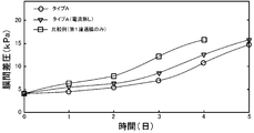
- the structure of the type A filtration membrane module 123A and the type B filtration membrane module 123B used in the experimental example in the second embodiment is shown. It is explanatory drawing which shows the relationship between time when using a type A filtration membrane module 123A, and transmembrane pressure difference.
- cleaning are shown.
- FIG. 1 is a configuration diagram showing an outline of the configuration of a water treatment system 20 as a first embodiment of the present invention
- FIG. 2 is a left side in FIG. 1 centering on a filtration membrane 24 of the water treatment system 20 of the first embodiment.
- It is a block diagram which shows the outline of a structure at the time of seeing from the surface.
- the water treatment system 20 of the first embodiment includes a filtration membrane 24 that forms a hollow portion that is disposed in the treatment tank 22 and takes out the treated water, and a supply pump 26 that supplies the treated water to the treatment tank 22.
- the anode 42 disposed on the surface of the filter membrane 24 at a first distance (1.5 cm in the first embodiment) so that the water to be treated can be satisfactorily passed through the filter membrane 24, and the filter membrane 24.
- the water treatment system 20 of the first embodiment includes various water quality sensors 52 that detect dissolved oxygen, pH, temperature, and the like of water to be treated, a water level sensor 54 that detects the water level of the treatment tank 22, and a filtration membrane 24.
- a pressure sensor 56 for detecting a transmembrane pressure difference as a pressure difference between both sides is attached.
- the anode 42 is made of six anode plates 42a to 42f formed of iridium dioxide-coated titanium (Ti / IrO 2 : titanium coated with iridium dioxide) and arranged in parallel in the horizontal direction. It is configured by being connected by a plurality of conductive connection lines 43. Therefore, the water to be treated can easily flow to the filtration membrane 24 through the space between the anode plates 42a to 42f.
- the anode 42 not only iridium dioxide-coated titanium (Ti / IrO 2 ) but also ruthenium dioxide-coated titanium (Ti / RuO 2 : titanium coated with ruthenium dioxide) or iridium dioxide / ruthenium dioxide mixed-coated titanium (Ti / (IrO 2 + RuO 2 ): Titanium coated with a mixture of iridium dioxide and ruthenium dioxide), boron-doped diamond (BDD), platinum (Pt), lead oxide (PbO 2 ), etc.
- the chlorine generation efficiency at the anode is Ti / IrO 2 > Ti / RuO 2 ⁇ Ti / (IrO 2 + RuO 2 ) >>BDD> Pt.
- the cathode 44 is formed of platinum-coated titanium (Ti / Pt: titanium coated with platinum) and has two cathode plates 44a and 44b arranged in parallel in the horizontal direction.
- the plurality of connecting lines 45 are connected to each other.
- platinum-coated titanium Ti / Pt
- platinum (Pt) platinum
- iron (Fe) iron
- Al aluminum
- carbon (C) titanium
- Ti titanium
- the water to be treated is filtered with aeration by the aeration apparatus 30 and application of current to the anode 42 and the cathode 44.
- FIG. 3 the effect
- the anode 42 and the cathode 44 are removed from the water treatment system 20 of the first embodiment.
- Some of the organic matter in the water to be treated (for example, binding extracellular polymer) becomes a colloidal soluble organic matter due to hydrolysis, diffusion, etc.
- the film is deposited on the filtration membrane 24 to increase the transmembrane pressure difference.
- the organic matter is directly oxidatively decomposed on the electrode surface of the anode 42, and the organic matter is indirectly oxidatively decomposed by the oxidative substance generated by the electrode reaction of the anode 42.
- Organic matter adhering to the surface is also indirectly oxidized and decomposed. That is, in the first embodiment, the amount of organic matter that causes clogging of the filtration membrane 24 is reduced, and the organic matter adhering to the surface of the filtration membrane 24 is also oxidatively decomposed and removed. The rise can be suppressed.
- colloidal soluble organic substances and solutes having an effective pore size less than that permeate the filtration membrane 24, it is possible to further suppress an increase in transmembrane pressure difference.
- Examples of the generation of the oxidative substance by the electrode reaction of the anode 42 include the following. (1) Hydroxy radical (.OH) (2) Hydrogen peroxide (H 2 O 2 ) (3) Ozone (O 3 ) (4) Chlorine and hypochlorous acid (ion) (Cl 2 , HClO, ClO ⁇ )
- the cathode 44 undergoes the following electrode reaction. (1) 2H 2 O + 2e ⁇ ⁇ H 2 + 2OH ⁇
- the specifications of the water treatment system of the experimental example are shown in the specifications table of FIG.
- the effective capacity of the treatment tank 22 is 5.5 (L).
- the membrane material of the filtration membrane 24 is made of polyvinylidene fluoride (PolyVinylidene DiFluoride: PVDF) (3)
- the nominal pore diameter of the filtration membrane 24 is 0.4 ( ⁇ m) (4)
- Effective membrane area is 500 (cm 2 ) (5)
- Average filtration flux is 0.35 (m 3 / m 2 d) (7 minute on and 1 minute off interval) (6)
- the aeration flow rate (aeration flow rate) by the aeration apparatus 30 is 2 (L / min).
- the hydraulic residence time in the treatment tank 22 is 8.7 (hr)
- Sludge residence time is 110 (day)
- the composition of the water to be treated used in the experimental example is shown in FIG.
- the treated water is assumed to be industrial wastewater and has a higher salt concentration (NaCl) than general municipal sewage in order to increase the current density.
- the composition is shown below.
- Yeast extract 40 (mg / L)
- FIG. 6 shows the relationship between time and transmembrane pressure difference in the first example and the comparative example when water treatment is continued in the experimental example.
- the “transmembrane differential pressure” is a pressure difference between both sides of the filtration membrane 24, and means that the greater the transmembrane pressure difference, the greater the clogging of the membrane.
- white circles are comparative examples (those with neither an anode nor a cathode)
- the black circles are the lower part of the legend on the upper left in the figure
- the current density of the current applied to is 0.4 (mA / cm 2 ).
- a downward triangle mark (middle of the legend on the upper left in the figure) is a reference example when no current is applied to the anode 42 and the cathode 44 in the first embodiment (current density is 0 (mA / cm 2 )).
- current density is 0 (mA / cm 2 )).
- the downward arrow in the figure indicates that physical cleaning was performed by backwashing with tap water after removing the cake layer on the surface of the filtration membrane 24 with a brush.
- physical cleaning is performed by increasing the transmembrane pressure difference five times in 14 days, 27 days, 33 days, 44 days, and 55 days in 57 days.
- physical cleaning is performed by increasing the transmembrane pressure difference five times on the 14th, 27th, 33rd, 44th, and 57th of 57 days.
- physical cleaning is performed by increasing the transmembrane pressure differential three times on the 16th, 36th, and 57th of 57 days. From this experimental example, by applying a current to the anode 42 and the cathode 44 of the water treatment system 20 of the first embodiment for water treatment, the frequency of physical cleaning is reduced to about 3/5 due to an increase in transmembrane pressure difference. I understand that you can.
- FIG. 8 shows the amounts of the soluble extracellular polymer and the binding extracellular polymer in the cake layer deposited on the surface of the filtration membrane 24 in the physical cleaning of the experimental example for the first example and the comparative example. Shown as a list.
- the amount of the soluble extracellular polymer is reduced as compared with the comparative example. This is because the amount of organic matter causing the clogging of the filtration membrane 24 is reduced due to the electrode reaction of the anode 42, the organic matter adhering to the surface of the filtration membrane 24 is indirectly removed by oxidative decomposition, the filtration membrane This is based on the fact that it is a colloidal soluble organic substance or solute having an effective pore size less than 24 that can pass through. Accordingly, it can be understood that an increase in filtration resistance can be suppressed by applying water to the anode 42 and the cathode 44 in the water treatment system 20 of the first embodiment to perform water treatment.
- FIG. 9 is an explanatory diagram showing the relationship between current density and substrate consumption rate
- FIG. 10 is an explanatory diagram showing the relationship between current density and ammonia consumption rate.
- TOC in the unit of substrate consumption rate means total organic carbon.
- a circle indicates a state after energization for 6 hours
- a downward triangle indicates a state after energization for 12 hours
- a square indicates a state after energization for 18 hours.
- the substrate consumption rate and the ammonia consumption rate indicate the activity of water treatment (biological treatment or microbial treatment) by microorganisms (aerobic microorganisms) contained in the water to be treated
- the current density is 0.8 as shown in the figure.
- the current applied to the anode 42 and the cathode 44 of the water treatment system 20 of the first embodiment is within the range of 0.1 (mA / cm 2 ) to 0.8 (mA / cm 2 ) as the current density.
- the water treatment activity by microorganisms is desirably about 0.4 (mA / cm 2 ), at which the activity does not decrease.
- the first distance (first embodiment) is placed on one surface of the filtration membrane 24.
- the anode 42 is arranged in a plane so that the flow of the water to be treated to the filtration membrane 24 can be satisfactorily performed with 1.5 cm), and the second distance (first implementation) is placed on the other surface of the filtration membrane 24.
- the cathode 44 is disposed so as to face the anode 42 at 3.0 cm), and a direct current is supplied to the anode 42 and the cathode 44, thereby causing the filtration membrane 24 to be blocked due to an electrode reaction or the like in the anode 42.
- the direct current applied to the anode 42 and the cathode 44 is in the range of 0.1 (mA / cm 2 ) to 0.8 (mA / cm 2 ), more preferably 0.4 (mA / cm 2 ).
- the anode 42 is arranged on one surface of the filtration membrane 24 with a first distance of 1.5 cm, but the distance between the filtration membrane 24 and the anode 42 is the same. Is not limited to 1.5 cm, as long as the anode 42 is not in contact with the cake layer deposited on the filtration membrane 24, and may be appropriately determined within a range of 1.0 cm to 3.0 cm, for example.
- the cathode 44 is disposed on the other surface of the filtration membrane 24 so as to face the anode 42 with a second distance of 3.0 cm.
- the distance from the cathode 44 is not limited to 3.0 cm, and may be determined as long as the filtration membrane 24 and the cathode 44 are not in contact with each other.
- the distance may be appropriately determined within a range of 1.0 cm to 5.0 cm. .
- anode plates 42a to 42f are arranged at substantially equal intervals in the horizontal direction, and these are connected by a plurality of conductive connection lines 43 to constitute the anode 42.
- the six anode plates 42a to 42f are substantially arranged in the vertical direction.
- the anodes may be arranged at equal intervals, the anodes may be configured in a mesh pattern, or the anodes may be configured in a grid pattern.
- the anode 42 is disposed almost on the entire upstream side of the filtration membrane 24 and the cathode 44 is disposed on the downstream side of the filtration membrane 24 so as to face the anode 42.
- An anode may be arranged on a part of the upstream side of the membrane such as half or 1/4 of the area of the membrane from the lower side.
- the filtration membrane module 23 is formed by the filtration membrane 24, the anode 42, and the cathode 44. That is, the filtration membrane module 23 has a filtration membrane 24 that forms a hollow portion for taking out treated water, and a surface of the filtration membrane 24 so that the water to be treated can be satisfactorily flowed to one side of the filtration membrane 24. And the cathode 44 disposed on the other surface of the filtration membrane 24 so as to face the anode 42.
- FIG. 11 is a configuration diagram showing an outline of the configuration of the water treatment system 120 as the second embodiment
- FIG. 12 is a configuration showing an outline of the configuration of the filtration membrane module 123 used in the water treatment system 120 of the second embodiment.
- the water treatment system 20 of the second embodiment is treated from a filtration membrane module 123 arranged in a treatment tank 122, a supply pump 126 for supplying treated water to the treatment tank 122, and a filtration membrane module 123.
- a discharge pump 128 that discharges water, an aeration device 130 that is disposed near the bottom of the treatment tank 122 and performs aeration on the water to be treated, and a DC power source 148 that supplies a DC current to the filtration membrane module 123 are provided.
- a pressure sensor 156 for detecting a transmembrane pressure difference at 123 is attached.
- the filtration membrane module 123 includes two first filtration membranes 124 forming a hollow portion 124a, and the first filtration membrane 124 and a first distance (first In the second embodiment, the two anodes 142 are arranged so that the flow of the water to be treated to the first filtration membrane 124 can be satisfactorily performed at 1.5 cm) and on both outer sides of the two anodes 142.
- a second filtration membrane 125 arranged with a second distance (3 cm in the second embodiment) from the anode 142, and a second filtration membrane 125 and a third distance (second implementation) on both outer sides of the second filtration membrane 125.
- the discharge pump 128 discharges the treated water in the hollow portion 124a.
- a polyethylene membrane (PE) having a nominal pore diameter of 0.4 ⁇ m can be used for the first filtration membrane 124, and a nonwoven fabric having a coarser mesh than the first filtration membrane 124 can be used for the second filtration membrane 125.
- the role of the second filtration membrane 125 is to suppress filtration clogging of the first filtration membrane 124 by removing relatively large suspended matters in the water to be treated. Therefore, the second filtration membrane 125 may be anything other than a nonwoven fabric, as long as it has a coarser mesh than the first filtration membrane 124.
- the anode 142 is formed of iridium dioxide-coated titanium (Ti / IrO 2 : titanium coated with iridium dioxide), and a plurality of anode plates arranged in parallel in the horizontal direction. Are connected by a plurality of conductive connection lines.
- the anode 142 not only iridium dioxide-coated titanium (Ti / IrO 2 ) but also ruthenium dioxide-coated titanium (Ti / RuO 2 : titanium coated with ruthenium dioxide) or iridium dioxide / ruthenium dioxide mixed-coated titanium (Ti / (IrO 2 + RuO 2 ): Titanium coated with a mixture of iridium dioxide and ruthenium dioxide), boron-doped diamond (BDD), platinum (Pt), lead oxide (PbO 2 ), etc. Can be used.
- the chlorine generation efficiency at the anode is Ti / IrO 2 > Ti / RuO 2 ⁇ Ti / (IrO 2 + RuO 2 ) >>BDD> Pt.
- the cathode 144 is made of a plurality of cathode plates made of platinum-coated titanium (Ti / Pt: titanium coated with platinum) and arranged in parallel in the horizontal direction. It is comprised by connecting with the some connection line which has.
- platinum-coated titanium Ti / Pt
- platinum (Pt) platinum
- iron (Fe) iron
- Al aluminum
- carbon (C) titanium
- Ti titanium
- the water to be treated is filtered with aeration by the aeration apparatus 130 and application of current to the anode 142 and the cathode 144.
- the organic matter is directly oxidatively decomposed on the electrode surface of the anode 142, and the organic matter is indirectly generated by the oxidative substance generated by the electrode reaction of the anode 142.
- the organic matter that has been oxidatively decomposed and adhered to the surface of the first filtration membrane 124 is also indirectly oxidatively decomposed.
- the amount of organic substances that cause clogging of the first filtration membrane 124 is reduced, and organic substances adhering to the surface of the first filtration membrane 124 are also oxidatively decomposed and removed, thereby suppressing an increase in transmembrane pressure difference.
- the second filtration membrane 125 having a coarser mesh than the first filtration membrane 124 is disposed on both outer sides of the first filtration membrane 124, the relatively large suspended matter in the treated water is second. Since it is captured by the filtration membrane 125, an increase in the transmembrane pressure difference of the first filtration membrane 124 can be suppressed.
- the specifications of the water treatment system of the experimental example are shown in the specification table of FIG.
- the effective capacity of the treatment tank 122 is 13 (L)
- the first filtration membrane 124 is made of polyethylene.
- the nominal pore diameter of the first filtration membrane 124 is 0.4 ( ⁇ m).
- the material of the second filtration membrane 125 is a nonwoven fabric.
- the membrane area is 1 (m 2 ) for the first filtration membrane 124 and 0.097 (m 2 ) for the second filtration membrane 125.
- the applied current to the anode 142 and the cathode 144 is 5 (mA / cm 2 ) (interval of 30 minutes on and 2 minutes 30 seconds off) (7)
- the average filtration flux is 0.31 (m 3 / m 2 d) for the first filtration membrane 124 and 3.17 (m 3 / m 2 d) for the second filtration membrane 125.
- the areas of the anode 142 and the cathode 144 are both 50 (cm 2 ).
- the composition of the water to be treated used in the experimental example is shown in FIG.
- the treated water was assumed to be general sewage.
- the composition is shown below.
- FIG. 15 shows configurations of a type A filtration membrane module 123A and a type B filtration membrane module 123B used in the experimental example.
- the anode 142 and the cathode 144 are arranged below the module
- the anode 142 and the cathode 144 are arranged in the center of the module. ing.
- FIG. 16 shows the relationship between time and transmembrane pressure difference when using a type A filtration membrane module 123A.
- the “transmembrane differential pressure” is a pressure difference between the hollow portion 124a of the filtration membrane module 123A and the processing tank 122, and means that the membrane clogging is larger as the transmembrane differential pressure is larger.
- a white circle mark (upper part of the legend on the upper left in the figure) is a current applied using a type A filtration membrane module 123A
- a white triangle mark (middle part of the legend on the upper left in the figure) indicates a type A filtration.
- the membrane module 123A was used but no current was applied, and the white square mark (lower part of the legend on the upper left in the figure) is only the first filtration membrane 124 that does not include the second filtration membrane 125, the anode 142, and the cathode 144.
- the filtration resistance that can be removed by physical washing is smaller when the type A filtration membrane module 123A is used even when no current is applied, but it is not further removed by physical cleaning when the current is applied. Filtration resistance is low. Thereby, it turns out that the effect of the physical washing
- FIG. 18 shows the relationship between time and transmembrane pressure difference when a type B filtration membrane module 123B is used.
- a white circle mark (upper part of the legend on the upper left in the figure) is a current applied using a type B filtration membrane module 123B
- a white triangle mark (middle part of the legend on the upper left in the figure) indicates a type B filtration.
- the membrane module 123B was used but no current was applied, and the white square mark (lower part of the legend at the upper left in the figure) is only the first filtration membrane 124 that does not include the second filtration membrane 125, the anode 142, and the cathode 144. It is a comparative example using the filtration membrane module of.
- the transmembrane differential pressure is smaller when the type B filtration membrane module 123B is used even when no current is applied as compared with the comparative example. However, when the current is applied, the transmembrane differential pressure is further increased. You can see that is getting smaller.
- the electrode reaction at the anode 142 and the like are performed.
- the amount of organic matter that causes clogging of the first filtration membrane 124 can be reduced, and the organic matter adhering to the surface of the first filtration membrane 124 can be oxidatively decomposed and removed, thereby suppressing an increase in filtration resistance in the first filtration membrane 124.
- the frequency of performing physical cleaning can be reduced as compared with the comparative example.
- the direct current applied to the anode 142 and the cathode 144 is a current density in the range of 0.1 (mA / cm 2 ) to 0.8 (mA / cm 2 ), more preferably 0.4 (mA / cm 2 ).
- the anode 142 is disposed with a first distance of 1.5 cm from the first filtration membrane 124.
- the distance between the first filtration membrane 24 and the anode 142 is 1.
- the thickness is not limited to 5 cm, and may be determined as long as the anode 142 is not in contact with the cake layer deposited on the first filter membrane 124. For example, the thickness may be appropriately determined within a range of 1.0 cm to 3.0 cm.
- the second filtration membrane 125 is arranged with a second distance of 3.0 cm from the anode 142, but the distance between the anode 142 and the second filtration membrane 125 is as follows.
- the thickness is not limited to 3.0 cm, and may be determined as long as the anode 142 and the second filtration membrane 125 are not in contact with each other. For example, the thickness may be appropriately determined within a range of 1.0 cm to 5.0 cm.
- the cathode 144 is disposed with a third distance of 3.0 cm from the second filtration membrane 125, but the distance between the second filtration membrane 125 and the cathode 144 is 3.
- the thickness is not limited to 0.0 cm, and may be determined as long as the second filtration membrane 125 and the cathode 144 are not in contact with each other, and may be appropriately determined within a range of 1.0 cm to 5.0 cm, for example.
- the anode 142 is configured by arranging a plurality of anode plates at substantially equal intervals in the horizontal direction and connecting them with a plurality of conductive connection lines.
- the anode is only required to be disposed in a plane so that the flow of the water to be treated to the first filtration membrane 124 can be satisfactorily performed. Therefore, a plurality of anode plates are disposed at substantially equal intervals in the vertical direction.
- the anode may be configured in a mesh pattern, or the anode may be configured in a grid pattern.
- the anode 142 and the cathode 144 are disposed below and in the center of the first filtration membrane 124. However, the anode and the cathode are disposed on the entire surface of the first filtration membrane 124. It may be a thing.
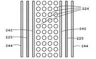
- FIG. 19 is a block diagram showing an outline of the configuration of a modified membrane membrane module 223, and FIG. 20 is a cross-sectional view taken along the line AA in FIG.
- the filtration membrane module 123 the two first filtration membranes 124 are arranged so as to face each other so that a flat hollow portion 124a is formed, and two outer sides of the two first filtration membranes 124 are arranged.
- the anode 142, the two second filtration membranes 125, and the two cathodes 144 are arranged in this order.
- a plurality of membrane tubes 224 may be arranged, and two anodes 242, two second filtration membranes 225, and two cathodes 244 may be arranged in that order on both outer sides thereof.
- the anode, the second filtration membrane, and the cathode may be arranged in a ring shape.
- the present invention can be used in the water treatment industry in the manufacturing industry of water treatment systems and filtration membrane modules and in water treatment facilities such as sewage treatment and wastewater treatment.
Landscapes
- Chemical & Material Sciences (AREA)
- Life Sciences & Earth Sciences (AREA)
- Organic Chemistry (AREA)
- Hydrology & Water Resources (AREA)
- Engineering & Computer Science (AREA)
- Environmental & Geological Engineering (AREA)
- Water Supply & Treatment (AREA)
- Chemical Kinetics & Catalysis (AREA)
- General Chemical & Material Sciences (AREA)
- Electrochemistry (AREA)
- Biodiversity & Conservation Biology (AREA)
- Microbiology (AREA)
- Water Treatment By Electricity Or Magnetism (AREA)
Abstract
エアレーションと濾過膜24による濾過とを用いて水処理する際に、濾過膜24の一方の面に第1の距離(1.5cm)をもって被処理水の濾過膜24への通流が良好に行なわれるように面的にアノード42を配置すると共に濾過膜24の他方の面に第2の距離(3.0cm)をもってアノード42に対向するようカソード44を配置し、アノード42とカソード44とに直流電流を印加する。これにより、濾過膜24の閉塞を引き起こす有機物量を減少すると共に濾過膜24の表面に付着した有機物をも酸化分解除去し、濾過膜24における濾過抵抗の上昇を抑制することができる。この結果、濾過膜24の洗浄を行なう頻度を少なくすることができる。
Description
本発明は、水処理システムおよび濾過膜モジュール並びに水処理方法に関し、詳しくは、好気性微生物の活性化を促すエアレーションと濾過膜による濾過とを用いて水処理する水処理システムおよびこの水処理システムに用いられる濾過膜モジュール並びに水処理方法に関する。
従来、この種の水処理システムとしては、汚水に含まれる汚物を分解する微生物が担持された基材に汚水を接触させ汚物を分解することによって汚水から生物処理水を得る生物処理装置と、生物処理水を濾過膜に透過させて生物処理水に含まれる汚物を含む濃縮処理水と濾過水とに物理的に分離する膜濾過装置と、濃縮処理水を含む処理水を固液分離する固液分離装置と、固液分離装置により固液分離された分離水を生物処理装置に循環させる循環装置とを備えるものが提案されている(例えば、特許文献1参照)。このシステムでは、膜濾過装置により分離された濃縮処理水が膜濾過装置内に滞留することなく外部に取り出されるため、濾過膜の閉塞を回避している。
上述の水処理システムのように、生物処理と濾過膜を用いる水処理では、濾過膜に汚物が堆積して膜間差圧(濾過膜の両側の圧力差)が上昇すると、塩素などの薬剤を用いて逆流洗浄などにより濾過膜を洗浄し、濾過性能を回復させることが行なわれている。したがって、膜間差圧の上昇を抑制することができれば、濾過膜の洗浄頻度を少なくすることができると共にシステムの小型化と効率化とを図ることができる。
本発明の水処理システムおよび濾過膜モジュール並びに水処理方法は、水処理システムの濾過膜における膜間差圧の上昇を抑制することを主目的とする。
本発明の水処理システムおよび濾過膜モジュール並びに水処理方法は、上述の主目的を達成するために以下の手段を採った。
本発明の水処理システムは、
好気性微生物の活性化を促すエアレーションと濾過膜による濾過とを用いて水処理する水処理システムであって、
前記濾過膜の上流側の少なくとも一部に、前記濾過膜による処理前の被処理水の前記濾過膜への通流が可能なように面的に配置されたアノードと、
前記アノードに対向するよう配置されたカソードと、
を備え、
水処理を行なうときには、前記アノードおよび前記カソードに直流電流を供給する、
ことを特徴とする。
好気性微生物の活性化を促すエアレーションと濾過膜による濾過とを用いて水処理する水処理システムであって、
前記濾過膜の上流側の少なくとも一部に、前記濾過膜による処理前の被処理水の前記濾過膜への通流が可能なように面的に配置されたアノードと、
前記アノードに対向するよう配置されたカソードと、
を備え、
水処理を行なうときには、前記アノードおよび前記カソードに直流電流を供給する、
ことを特徴とする。
この本発明の水処理システムでは、アノードの表面で有機物を酸化分解する直接的分解と、酸化分解等により生成した酸化的物質が有機物を分解する間接的分解と、が行なわれる。こうした有機物の直接的分解と間接的分解とにより、濾過膜に堆積する堆積量を少なくして、濾過膜の両側の圧力差としての膜間差圧の上昇を抑制することができる。この結果、水処理システムの小型化や効率化を図ることができる。なお、アノードは濾過膜の上流側の全面に亘って面的に配置されている必要はなく、その一部に面的に配置されていてもよい。
こうした本発明の水処理システムにおいて、前記カソードは、前記アノードに対して前記濾過膜を挟んで対向するよう配置されているものとすることもできる。カソードはアノードに対向して配置されていればよいからである。この場合、前記アノードは、前記濾過膜に1.0cm~3.0cmの範囲内の距離をもって配置されており、前記カソードは、前記濾過膜に1.0cm~5.0cmの範囲内の距離をもって配置されている、ことを特徴とするものとすることもできる。これらの距離は適合値であり、大きすぎると、電流を流すのに必要な電圧が高くなり、小さすぎると、アノードと濾過膜との間に堆積物が溜まってしまうことに基づく。
また、本発明の水処理システムにおいて、前記アノードの上流側に前記濾過膜と略平行に配置された前記濾過膜より目の粗い第2の濾過膜を備え、前記カソードは、前記第2の濾過膜の上流側に配置されている、ことを特徴とするものとすることもできる。このように濾過膜より目の粗い第2の濾過膜を備えることにより、有効径の大きな堆積物を第2の濾過膜に堆積させることができ、濾過膜の堆積量を少なくすることができる。この結果、濾過膜の両側の圧力差としての膜間差圧の上昇を抑制することができる。また、カソードを第2の濾過膜を挟んでアノードに対向するように配置するから、濾過膜の略全面に亘ってアノードとカソードを配置することができ、アノードによる有機物の酸化分解の効果を濾過膜全面に奏することができる。
こうした第2の濾過膜を備える態様の本発明の水処理システムにおいて、前記第2の濾過膜は不織布により形成されているものとすることもできる。また、前記アノードは前記濾過膜に1.0cm~3.0cmの範囲内の距離をもって配置されており、前記第2の濾過膜は前記アノードに1.0cm~3.0cmの範囲内の距離をもって配置されており、前記カソードは前記第2の濾過膜に1.0cm~5.0cmの範囲内の距離をもって配置されている、ことを特徴とするものとすることもできる。これらの距離は適合値であり、大きすぎると、電流を流すのに必要な電圧が高くなり、小さすぎると、アノードと濾過膜との間に堆積物が溜まってしまうことに基づく。
こうした本発明の水処理システムにおいて、アノードとしては、二酸化イリジウム被覆チタン(Ti/IrO2:チタンを二酸化イリジウムで被覆したもの)、二酸化ルテニウム被覆チタン(Ti/RuO2:チタンを二酸化ルテニウムで被覆したもの)、二酸化イリジウム・二酸化ルテニウム混合被覆チタン(Ti/(IrO2+RuO2):チタンを二酸化イリジウムと二酸化ルテニウムとの混合物で被覆したもの)、ボロン・ドープド・ダイアモンド(BDD:Boron-doped diamond)、白金(Pt)、酸化鉛(PbO2)などを用いることができる。また、カソードとしては、白金被覆チタン(Ti/Pt:チタンを白金で被覆したもの)、白金(Pt)、鉄(Fe)、アルミニウム(Al)、炭素(C)、チタン(Ti)などを用いることができる。
また、本発明の水処理システムにおいて、アノードとカソードに供給される直流電流は、電流密度として0.1mA/cm2~0.8mA/cm2の範囲内となるよう調整されているのが好ましい。これは、0.1mA/cm2未満では電極反応による有機物の酸化分解量が小さくなり、0.8mA/cm2を超えると、微生物による有機物の分解活性が低下してしまうことに基づく。したがって、電流密度を上述の範囲内とすることにより、電極反応による有機物の酸化分解と微生物による有機物の分解活性との双方により水処理を効率よく行なうことができる。
さらに、本発明の水処理システムにおいて、アノードは、網目,格子,複数列のうちのいずれかにより面的に配置されているものとすることもできる。これは、非濾過水を濾過膜に通流させる必要性に基づいている。
本発明の濾過膜モジュールは、
好気性微生物の活性化を促すエアレーションを用いて水処理する水処理システムに用いられる濾過膜モジュールであって、
濾過処理水を取り出すための中空部を形成するように配置された濾過膜と、
前記濾過膜の外周側の少なくとも一部に、濾過処理前の被処理水の前記濾過膜への通流が可能なように面的に配置されたアノードと、
前記アノードに対向するよう配置されたカソードと、
を備えることを要旨とする。
好気性微生物の活性化を促すエアレーションを用いて水処理する水処理システムに用いられる濾過膜モジュールであって、
濾過処理水を取り出すための中空部を形成するように配置された濾過膜と、
前記濾過膜の外周側の少なくとも一部に、濾過処理前の被処理水の前記濾過膜への通流が可能なように面的に配置されたアノードと、
前記アノードに対向するよう配置されたカソードと、
を備えることを要旨とする。
この本発明の濾過膜モジュールでは、濾過膜は濾過処理水を取り出すための中空部を形成するように配置されており、アノードは濾過膜の外周側の少なくとも一部に濾過処理前の被処理水の濾過膜への通流が可能なように面的に配置されており、カソードはアノードに対向するよう配置されている。こうした濾過膜モジュールを対象の被処理水に浸漬させ、エアレーションを行なうと共にアノードとカソードとに直流電流を供給し、中空部から処理水を取り出すように作動させることにより、水処理を行なう。アノードの表面では有機物を酸化分解する直接的分解と、この酸化分解等により生成した酸化的物質が有機物を分解する間接的分解とが行なわれるから、濾過膜に堆積する堆積量を少なくして、濾過膜の両側の圧力差としての膜間差圧の上昇を抑制することができる。この結果、濾過膜モジュールの水処理における効率化を図ることができる。なお、アノードは濾過膜の外周側の少なくとも一部に配置されていればよく、全面に亘って面的に配置されている必要はない。
こうした本発明の濾過膜モジュールにおいて、前記カソードは、前記濾過膜の外周側に前記アノードとによって前記濾過膜を挟むように配置されている、ものとすることもできる。
また、本発明の濾過膜のモジュールにおいて、前記濾過膜より目が粗く前記アノードの外周側に配置された第2の濾過膜を備え、前記カソードは、前記第2の濾過膜の外周側に配置されている、ものとすることもできる。このように濾過膜より目の粗い第2の濾過膜を備えることにより、有効径の大きな堆積物を第2の濾過膜に堆積させることができ、濾過膜の堆積量を少なくすることができる。この結果、濾過膜の両側の圧力差としての膜間差圧の上昇を抑制することができる。
さらに、本発明の濾過膜モジュールにおいて、アノードとしては、二酸化イリジウム被覆チタン(Ti/IrO2)、二酸化ルテニウム被覆チタン(Ti/RuO2)、二酸化イリジウム・二酸化ルテニウム混合被覆チタン(Ti/(IrO2+RuO2)、ボロン・ドープド・ダイアモンド(BDD:Boron-doped diamond)、白金(Pt)、酸化鉛(PbO2)を用いることができる。また、カソードとしては、白金被覆チタン(Ti/Pt)、白金(Pt)、鉄(Fe)、アルミニウム(Al)、炭素(C)、チタン(Ti)を用いることができる。
本発明の水処理方法は、
好気性微生物の活性化を促すエアレーションと濾過膜による濾過とを用いて水処理する水処理方法であって、
水処理中に、前記濾過膜の上流側の少なくとも一部に前記濾過膜による処理前の被処理水の前記濾過膜への通流が可能なように面的に配置されたアノードと、前記アノードに対向するよう配置されたカソードとに、電流密度として0.1mA/cm2~0.8mA/cm2の範囲内の直流電流を印加する、
ことを特徴とする。
好気性微生物の活性化を促すエアレーションと濾過膜による濾過とを用いて水処理する水処理方法であって、
水処理中に、前記濾過膜の上流側の少なくとも一部に前記濾過膜による処理前の被処理水の前記濾過膜への通流が可能なように面的に配置されたアノードと、前記アノードに対向するよう配置されたカソードとに、電流密度として0.1mA/cm2~0.8mA/cm2の範囲内の直流電流を印加する、
ことを特徴とする。
この本発明の水処理方法では、アノードの表面で有機物を酸化分解する直接的分解と、酸化分解等により生成した酸化的物質が有機物を分解する間接的分解と、が行なわれる。こうした有機物の直接的分解と間接的分解とにより、濾過膜に堆積する堆積量を少なくして、膜間差圧の上昇を抑制することができる。この結果、水処理システムの小型化や効率化を図ることができる。なお、アノードは濾過膜の一方の面側に全面に亘って面的に配置されている必要はなく、その一部に面的に配置されていてもよい。
次に、本発明を実施するための形態を実施例を用いて説明する。
図1は本発明の第1実施例としての水処理システム20の構成の概略を示す構成図であり、図2は第1実施例の水処理システム20の濾過膜24を中心に図1中左側面から見た際の構成の概略を示す構成図である。第1実施例の水処理システム20は、図示するように、処理槽22に配置され処理水を取り出す中空部を形成する濾過膜24と、処理槽22に被処理水を供給する供給ポンプ26と、濾過膜24に形成された中空部の処理水を排出する排出ポンプ28と、処理槽22の底部近傍に配置されて被処理水に対してエアレーションを行なうエアレーション装置30と、濾過膜24の一方の面に第1の距離(第1実施例では、1.5cm)をもって被処理水の濾過膜24への通流が良好に行なわれるように面的に配置されたアノード42と、濾過膜24の他方の面に第2の距離(第1実施例では、3.0cm)をもってアノード42に対向するよう配置されたカソード44と、アノード42とカソード44とに直流電流を供給する直流電源48と、を備える。なお、第1実施例の水処理システム20には、被処理水の溶存酸素やPH,温度などを検出する各種水質センサ52や、処理槽22の水位を検出する水位センサ54,濾過膜24の両側の圧力差としての膜間差圧を検出するための圧力センサ56などが取り付けられている。
アノード42は、第1実施例では、二酸化イリジウム被覆チタン(Ti/IrO2:チタンを二酸化イリジウムで被覆したもの)により形成されて水平方向に平行に配置された6本のアノード板42a~42fを導電性を有する複数の連結ライン43により連結することにより構成されている。したがって、被処理水は、アノード板42a~42fの間を通って容易に濾過膜24に流れることができる。アノード42としては、二酸化イリジウム被覆チタン(Ti/IrO2)だけでなく、二酸化ルテニウム被覆チタン(Ti/RuO2:チタンを二酸化ルテニウムで被覆したもの)や二酸化イリジウム・二酸化ルテニウム混合被覆チタン(Ti/(IrO2+RuO2):チタンを二酸化イリジウムと二酸化ルテニウムとの混合物で被覆したもの)、ボロン・ドープド・ダイアモンド(BDD:Boron-doped diamond)、白金(Pt)、酸化鉛(PbO2)などを用いることができる。これらのうちアノードにおける塩素生成効率としては、Ti/IrO2>Ti/RuO2≒Ti/(IrO2+RuO2)>>BDD>Ptとなる。
カソード44は、第1実施例では、白金被覆チタン(Ti/Pt:チタンを白金で被覆したもの)により形成されて水平方向に平行に配置された2枚のカソード板44a,44bを導電性を有する複数の連結ライン45により連結することにより構成されている。カソード44としては、白金被覆チタン(Ti/Pt)だけでなく、白金(Pt)や鉄(Fe)、アルミニウム(Al)、炭素(C)、チタン(Ti)などを用いることができる。
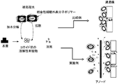
こうして構成された第1実施例の水処理システム20では、エアレーション装置30によるエアレーションとアノード42およびカソード44への電流の印加を伴って被処理水の濾過処理が行なわれる。図3に、第1実施例の水処理システム20におけるアノード42による作用を比較例と共に模式的に示す。ここで、比較例としては、第1実施例の水処理システム20からアノード42およびカソード44を除いたものである。被処理水中の有機物(例えば、結合性細胞外高分子ポリマーなど)は、加水分解や拡散などによりその一部は、コロイド状の溶解性有機物となるが、多くはそのままの形態を保持するため、比較例に示すように、濾過膜24に堆積し、膜間差圧を上昇させる。一方、第1実施例では、アノード42の電極表面で有機物が直接的に酸化分解されると共にアノード42の電極反応によって生成される酸化的物質により有機物が間接的に酸化分解され、濾過膜24の表面に付着した有機物も間接的に酸化分解される。即ち、第1実施例では、濾過膜24の閉塞を引き起こす有機物量を減少すると共に濾過膜24の表面に付着した有機物も酸化分解除去することにより、比較例に比して、膜間差圧の上昇を抑制することができる。また、有効孔径未満のコロイド状の溶解性有機物や溶質は濾過膜24を透過するため、膜間差圧の上昇を更に抑制することができる。
アノード42の電極反応による酸化的物質の生成としては、以下のものを挙げることができる。
(1)ヒドロキシラジカル(・OH)
(2)過酸化水素(H2O2)
(3)オゾン(O3)
(4)塩素および次亜塩素酸(イオン)(Cl2,HClO,ClO-)
(1)ヒドロキシラジカル(・OH)
(2)過酸化水素(H2O2)
(3)オゾン(O3)
(4)塩素および次亜塩素酸(イオン)(Cl2,HClO,ClO-)
アノード42において想定される反応は以下のとおりである。以下で、「M」は電極を形成する金属を示しており、「R」は有機物を示しており、「Products」は有機物が分解されて得られるものを示している。
(1)M+H2O→M(・OH)+H++e-
(2)M(・OH)+R→M+Products
(3)M(・OH)→M+(1/2)O2+H++e-
(4)2M(・OH)→2M+H2O2
(5)・OH→・O+H++e-+O2→O3
(6)M+Cl-→M(・Cl)+e-,2M(・Cl)→2M+Cl2
(7)Cl2+H2O←→HClO+Cl-+H+
(8)HClO←→ClO-+H+
(1)M+H2O→M(・OH)+H++e-
(2)M(・OH)+R→M+Products
(3)M(・OH)→M+(1/2)O2+H++e-
(4)2M(・OH)→2M+H2O2
(5)・OH→・O+H++e-+O2→O3
(6)M+Cl-→M(・Cl)+e-,2M(・Cl)→2M+Cl2
(7)Cl2+H2O←→HClO+Cl-+H+
(8)HClO←→ClO-+H+
なお、カソード44では、以下の電極反応が生じる。
(1)2H2O+2e-→H2+2OH-
(1)2H2O+2e-→H2+2OH-
次に、第1実施例の水処理システム20による具体的な実験例を示す。実験例の水処理システムの諸元を図4の諸元表に示す。実験例では、図4に示すように、以下の諸元とした。
(1)処理槽22の有効容量を5.5(L)
(2)濾過膜24の膜材質をポリフッ化ビニリデン(PolyVinylidene DiFluoride:PVDF)
(3)濾過膜24の公称孔径を0.4(μm)
(4)有効膜面積を500(cm2)
(5)平均濾過フラックスを0.35(m3/m2 d)(7分間オンで1分間オフのインターバル)
(6)エアレーション装置30によるエアレーション流量(散気流量)を2(L/min)
(7)処理槽22における水理学的滞留時間を8.7(hr)
(8)汚泥滞留時間を110(day)
(1)処理槽22の有効容量を5.5(L)
(2)濾過膜24の膜材質をポリフッ化ビニリデン(PolyVinylidene DiFluoride:PVDF)
(3)濾過膜24の公称孔径を0.4(μm)
(4)有効膜面積を500(cm2)
(5)平均濾過フラックスを0.35(m3/m2 d)(7分間オンで1分間オフのインターバル)
(6)エアレーション装置30によるエアレーション流量(散気流量)を2(L/min)
(7)処理槽22における水理学的滞留時間を8.7(hr)
(8)汚泥滞留時間を110(day)
実験例で用いた被処理水の組成を図5に示す。被処理水は、産業排水を想定し、電流密度を高めるために、一般的な都市下水よりも塩濃度(NaCl)を高めのものとした。組成を以下に示す。
(1)グルコース(Glucose)をCOD(Chemical Oxygen Demand:化学的酸素要求量)として300(mg/L)
(2)酵母エキス(Yeast extract)を40(mg/L)
(3)塩化アンモニウム(NH4Cl)をアンモニウムイオン(NH4 +)の窒素(N)として30(mg/L)
(4)リン酸一カリウム(KH2PO4)とリン酸水素二カリウム(K2HPO4)をリン酸イオン(PO4 -)としてのリン(P)として5(mg/L)
(5)塩化ナトリウム(NaCl)を塩素イオン(Cl-)として355(mg/L)
(6)塩化カルシウム・二水和物(CaCl2・2H2O)を14(mg/L)
(7)塩化カリウム(KCl)を36(mg/L)
(8)硫酸マグネシウム七水和物(MgSO4・7H2O)を90(mg/L)
(9)炭酸水素ナトリウム(NaHCO3)を126(mg/L)
(10)塩化鉄(III)・六水和物(FeCl3・6H2O)を0.45(mg/L)
(11)ホウ酸(H3BO3)を0.045(mg/L)
(12)硫酸銅・五水和物(CuSO4・5H2O)を0.009(mg/L)
(13)ヨウ化カリウム(KI)を0.054(mg/L)
(14)塩化マンガン・二水和物(MnCl2・2H2O)を0.036(mg/L)
(15)モリブデン酸ナトリウム・二水和物(Na2MoO4・2H2O)を0.018(mg/L)
(16)硫酸亜鉛・七水和物(ZnSO4・7H2O)を0.003(mg/L)
(17)塩化コバルト・六水和物(CoCl2・6H2O)を0.045(mg/L)
(1)グルコース(Glucose)をCOD(Chemical Oxygen Demand:化学的酸素要求量)として300(mg/L)
(2)酵母エキス(Yeast extract)を40(mg/L)
(3)塩化アンモニウム(NH4Cl)をアンモニウムイオン(NH4 +)の窒素(N)として30(mg/L)
(4)リン酸一カリウム(KH2PO4)とリン酸水素二カリウム(K2HPO4)をリン酸イオン(PO4 -)としてのリン(P)として5(mg/L)
(5)塩化ナトリウム(NaCl)を塩素イオン(Cl-)として355(mg/L)
(6)塩化カルシウム・二水和物(CaCl2・2H2O)を14(mg/L)
(7)塩化カリウム(KCl)を36(mg/L)
(8)硫酸マグネシウム七水和物(MgSO4・7H2O)を90(mg/L)
(9)炭酸水素ナトリウム(NaHCO3)を126(mg/L)
(10)塩化鉄(III)・六水和物(FeCl3・6H2O)を0.45(mg/L)
(11)ホウ酸(H3BO3)を0.045(mg/L)
(12)硫酸銅・五水和物(CuSO4・5H2O)を0.009(mg/L)
(13)ヨウ化カリウム(KI)を0.054(mg/L)
(14)塩化マンガン・二水和物(MnCl2・2H2O)を0.036(mg/L)
(15)モリブデン酸ナトリウム・二水和物(Na2MoO4・2H2O)を0.018(mg/L)
(16)硫酸亜鉛・七水和物(ZnSO4・7H2O)を0.003(mg/L)
(17)塩化コバルト・六水和物(CoCl2・6H2O)を0.045(mg/L)
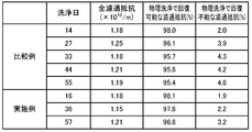
図6に、実験例で水処理を継続した際の第1実施例と比較例における時間と膜間差圧との関係を示す。ここで、「膜間差圧」は、濾過膜24の膜両側の圧力の差であり、膜間差圧が大きいほど膜目詰まりが大きいことを意味する。図中、白丸印(図中左上の凡例の上段)は比較例(アノードもカソードもないもの)であり、黒丸印(図中左上の凡例の下段)は第1実施例でアノード42とカソード44に印加した電流の電流密度を0.4(mA/cm2)としたときのものである。なお、図中、下向きの三角印(図中左上の凡例の中段)は参考例として第1実施例でアノード42とカソード44に電流を印加しない場合(電流密度を0(mA/cm2)としたとき)のものである。また、図中、下向き矢印は、ブラシにて濾過膜24の表面のケーキ層を除去した後に水道水で逆流洗浄する物理洗浄を行なったことを示している。図示するように、比較例では、57日間のうち、14日、27日、33日、44日、55日の5回、膜間差圧の上昇により物理洗浄が行なわれている。参考例では、57日間のうち、14日、27日、33日、44日、57日の5回、膜間差圧の上昇により物理洗浄が行なわれている。第1実施例では、57日間のうち、16日、36日、57日の3回、膜間差圧の上昇により物理洗浄が行なわれている。この実験例から、第1実施例の水処理システム20のアノード42とカソード44に電流を印加して水処理することにより、膜間差圧の上昇により物理洗浄の頻度を3/5程度に少なくすることができることが解る。第1実施例と比較例に対する実験例における物理洗浄を行なった洗浄日、全濾過抵抗、物理洗浄で回復可能な濾過抵抗の割合(%)、物理洗浄で回復不能な濾過抵抗の割合(%)の一覧を図7に示す。図示するように、第1実施例における物理洗浄で回復不能な濾過抵抗の割合(%)は比較例より小さくなっている。これにより、第1実施例の水処理システム20でアノード42とカソード44に電流を印加して水処理したときの物理洗浄の洗浄効果は、比較例に比して良いことが解る。
図8に、第1実施例と比較例に対する実験例の物理洗浄の際に濾過膜24の表面に堆積したケーキ層中の溶解性細胞外高分子ポリマーと結合性細胞外高分子ポリマーの量を一覧表として示す。第1実施例では、比較例に比して、溶解性細胞外高分子ポリマーの量が減少している。これは、アノード42の電極反応等により、濾過膜24の閉塞を引き起こす有機物量が減少していること、濾過膜24の表面に付着した有機物が間接的に酸化分解除去されていること、濾過膜24を透過可能な有効孔径未満のコロイド状の溶解性有機物や溶質になっていること、などに基づく。これにより、第1実施例の水処理システム20でアノード42とカソード44に電流を印加して水処理することにより、濾過抵抗の上昇を抑制することができるのが解る。
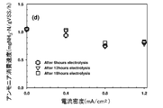
図9は電流密度と基質消費速度との関係を示す説明図であり、図10は電流密度とアンモニア消費速度との関係を示す説明図である。ここで、基質消費速度の単位中「TOC」は、全有機炭素(Total Organic Carbon)を意味している。また、図中、丸印は6時間の通電後の状態を示し、下向き三角印は12時間の通電後の状態を示し、四角印は18時間の通電後の状態を示す。基質消費速度とアンモニア消費速度は、被処理水に含まれる微生物(好気性微生物)による水処理(生物処理あるいは微生物処理)の活性を示しているから、図示するように、電流密度が0.8(mA/cm2)以上となると、微生物による活性が低下する。これにより、第1実施例の水処理システム20のアノード42とカソード44に印加する電流は、電流密度として0.1(mA/cm2)~0.8(mA/cm2)までの範囲内、特に微生物による水処理の活性が低下しない0.4(mA/cm2)前後であることが望ましいことが解る。
以上説明した第1実施例の水処理システム20によれば、エアレーションと濾過膜24による濾過とを用いて水処理する際に、濾過膜24の一方の面に第1の距離(第1実施例では、1.5cm)をもって被処理水の濾過膜24への通流が良好に行なわれるように面的にアノード42を配置すると共に濾過膜24の他方の面に第2の距離(第1実施例では、3.0cm)をもってアノード42に対向するようカソード44を配置し、アノード42とカソード44とに直流電流を供給することにより、アノード42における電極反応等により、濾過膜24の閉塞を引き起こす有機物量を減少すると共に濾過膜24の表面に付着した有機物をも酸化分解除去し、濾過膜24における濾過抵抗の上昇を抑制することができる。この結果、比較例に比して、濾過膜24の物理洗浄を行なう頻度を少なくすることができる。しかも、アノード42とカソード44とに印加する直流電流を電流密度として0.1(mA/cm2)~0.8(mA/cm2)の範囲内、更に好ましくは0.4(mA/cm2)前後とすることにより、微生物による水処理の活性の低下を抑制することができるから、微生物による水処理の効果に重畳的にアノード42の電極反応による水処理の効果を加えることができる。これらの結果、水処理システム20の小型化や高効率化を図ることができる。
第1実施例の水処理システム20では、濾過膜24の一方の面に第1の距離として1.5cmをもって面的にアノード42を配置するものとしたが、濾過膜24とアノード42との距離は1.5cmに限定されるものではなく、アノード42が濾過膜24に堆積するケーキ層に接触しない程度であればよいから、例えば1.0cm~3.0cmの範囲内で適宜決めればよい。また、第1実施例の水処理システム20では、濾過膜24の他方の面に第2の距離として3.0cmをもってアノード42に対向するようカソード44を配置するものとしたが、濾過膜24とカソード44との距離は3.0cmに限定されるものではなく、濾過膜24とカソード44とが接触しない程度であればよいから、例えば1.0cm~5.0cmの範囲内で適宜決めればよい。
第1実施例の水処理システム20では、6本のアノード板42a~42fを水平方向に略等間隔に配置し、これらを導電性を有する複数の連結ライン43により連結することによってアノード42を構成するものとしたが、アノードは、被処理水の濾過膜24への通流が良好に行なわれるよう面的に配置されていればよいから、6本のアノード板42a~42fを垂直方向に略等間隔に配置するものとしたり、アノードを網目状に構成したり、アノードを格子状に構成したりしてもよい。
第1実施例の水処理システム20では、濾過膜24の上流側のほぼ全面にアノード42を配置すると共に濾過膜24の下流側にアノード42に対向するようカソード44を配置するものとしたが、濾過膜の上流側に下方から濾過膜の面積の半分や1/4などのように一部にアノードを配置するものとしてもよい。
なお、第1実施例の水処理システム20では、濾過膜24とアノード42とカソード44とにより濾過膜モジュール23が形成されている。即ち、濾過膜モジュール23は、処理水を取り出す中空部を形成する濾過膜24と、濾過膜24の一方の面に被処理水の濾過膜24への通流が良好に行なわれるように面的に配置されたアノード42と、濾過膜24の他方の面にアノード42に対向するよう配置されたカソード44とにより形成されている。
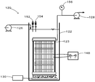
次に、本発明の第2実施例の水処理システム120について説明する。図11は第2実施例としての水処理システム120の構成の概略を示す構成図であり、図12は第2実施例の水処理システム120に用いられる濾過膜モジュール123の構成の概略を示す構成図である。第2実施例の水処理システム20は、図示するように、処理槽122に配置された濾過膜モジュール123と、処理槽122に被処理水を供給する供給ポンプ126と、濾過膜モジュール123から処理水を排出する排出ポンプ128と、処理槽122の底部近傍に配置されて被処理水に対してエアレーションを行なうエアレーション装置130と、濾過膜モジュール123に直流電流を供給する直流電源148と、を備える。なお、第2実施例の水処理システム120でも、被処理水の溶存酸素やPH,温度などを検出する各種水質センサ152や、処理槽122の水位を検出する水位センサ154,濾過膜濾過膜モジュール123における膜間差圧を検出するための圧力センサ156などが取り付けられている。
濾過膜モジュール123は、図12に示すように、中空部124aを形成する2枚の第1濾過膜124と、第1濾過膜124の両外側に第1濾過膜124と第1の距離(第2実施例では、1.5cm)をもって被処理水の第1濾過膜124への通流が良好に行なわれるように面的に配置された2つのアノード142と、2つのアノード142の両外側にアノード142と第2の距離(第2実施例では、3cm)をもって配置された第2濾過膜125と、第2濾過膜125の両外側に第2濾過膜125と第3の距離(第2実施例では、3.0cm)をもって被処理水の第2濾過膜125への通流が良好に行なわれるように面的に配置された2つのカソード144と、を備える。なお、排出ポンプ128は、中空部124aの処理水を排出することになる。
第1濾過膜124は、例えば、公称孔径が0.4μmのポリエチレン膜(PE)を用いることができ、第2濾過膜125は、第1濾過膜124より目が粗い不織布を用いることができる。ここで、第2濾過膜125の役割は、被処理水中の比較的大きな浮遊物を除去することにより、第1濾過膜124の濾過閉塞を抑制することである。したがって、第2濾過膜125は、第1濾過膜124より目が粗いものであればよいから、不織布以外を用いてもよい。
アノード142は、第1実施例のアノード42と同様に、二酸化イリジウム被覆チタン(Ti/IrO2:チタンを二酸化イリジウムで被覆したもの)により形成されて水平方向に平行に配置された複数のアノード板を導電性を有する複数の連結ラインにより連結することにより構成されている。アノード142としては、二酸化イリジウム被覆チタン(Ti/IrO2)だけでなく、二酸化ルテニウム被覆チタン(Ti/RuO2:チタンを二酸化ルテニウムで被覆したもの)や二酸化イリジウム・二酸化ルテニウム混合被覆チタン(Ti/(IrO2+RuO2):チタンを二酸化イリジウムと二酸化ルテニウムとの混合物で被覆したもの)、ボロン・ドープド・ダイアモンド(BDD:Boron-doped diamond)、白金(Pt)、酸化鉛(PbO2)などを用いることができる。これらのうちアノードにおける塩素生成効率としては、Ti/IrO2>Ti/RuO2≒Ti/(IrO2+RuO2)>>BDD>Ptとなる。
カソード144も、第1実施例のカソード44と同様に、白金被覆チタン(Ti/Pt:チタンを白金で被覆したもの)により形成されて水平方向に平行に配置された複数のカソード板を導電性を有する複数の連結ラインにより連結することにより構成されている。カソード144としては、白金被覆チタン(Ti/Pt)だけでなく、白金(Pt)や鉄(Fe)、アルミニウム(Al)、炭素(C)、チタン(Ti)などを用いることができる。
こうして構成された第2実施例の水処理システム120では、エアレーション装置130によるエアレーションとアノード142およびカソード144への電流の印加を伴って被処理水の濾過処理が行なわれる。第2実施例でも、図3を用いて説明したように、アノード142の電極表面で有機物が直接的に酸化分解されると共にアノード142の電極反応によって生成される酸化的物質により有機物が間接的に酸化分解され、第1濾過膜124の表面に付着した有機物も間接的に酸化分解される。即ち、第2実施例でも、第1濾過膜124の閉塞を引き起こす有機物量を減少すると共に第1濾過膜124の表面に付着した有機物も酸化分解除去することにより、膜間差圧の上昇を抑制する。第2実施例では、第1濾過膜124の両外側に、第1濾過膜124より目の粗い第2濾過膜125を配置しているから、被処理水中の比較的大きな浮遊物については第2濾過膜125により捕捉するため、第1濾過膜124の膜間差圧の上昇を抑制することができる。
アノード142の電極反応による酸化的物質の生成やアノード142において想定される反応、カソード144の電極反応などについては、第1実施例と同様であり、これらについては詳述した。
次に、第2実施例の水処理システム120による具体的な実験例を示す。実験例の水処理システムの諸元を図13の諸元表に示す。実験例では、図13に示すように、以下の諸元とした。
(1)処理槽122の有効容量を13(L)
(2)第1濾過膜124の膜材質をポリエチレン(polyethylene)
(3)第1濾過膜124の公称孔径を0.4(μm)
(4)第2濾過膜125の材質を不織布
(5)膜面積を第1濾過膜124で1(m2)、第2濾過膜125で0.097(m2)
(6)アノード142およびカソード144への印加電流を5(mA/cm2)(30秒オンで2分30秒オフのインターバル)
(7)平均濾過フラックスを第1濾過膜124で0.31(m3/m2 d)、第2濾過膜125で3.17(m3/m2 d)
(8)アノード142およびカソード144の面積を共に50(cm2)
(1)処理槽122の有効容量を13(L)
(2)第1濾過膜124の膜材質をポリエチレン(polyethylene)
(3)第1濾過膜124の公称孔径を0.4(μm)
(4)第2濾過膜125の材質を不織布
(5)膜面積を第1濾過膜124で1(m2)、第2濾過膜125で0.097(m2)
(6)アノード142およびカソード144への印加電流を5(mA/cm2)(30秒オンで2分30秒オフのインターバル)
(7)平均濾過フラックスを第1濾過膜124で0.31(m3/m2 d)、第2濾過膜125で3.17(m3/m2 d)
(8)アノード142およびカソード144の面積を共に50(cm2)
実験例で用いた被処理水の組成を図14に示す。被処理水は、一般的な下水を想定した。組成を以下に示す。
(1)グルコース(Glucose)をCOD(Chemical Oxygen Demand:化学的酸素要求量)として100(mg/L)
(2)塩化アンモニウム(NH4Cl)をアンモニウムイオン(NH4 +)の窒素(N)として10(mg/L)
(3)リン酸一カリウム(KH2PO4)とリン酸水素二カリウム(K2HPO4)をリン酸イオン(PO4 -)としてのリン(P)として2(mg/L)
(4)塩化ナトリウム(NaCl)を塩素イオン(Cl-)として118(mg/L)
(1)グルコース(Glucose)をCOD(Chemical Oxygen Demand:化学的酸素要求量)として100(mg/L)
(2)塩化アンモニウム(NH4Cl)をアンモニウムイオン(NH4 +)の窒素(N)として10(mg/L)
(3)リン酸一カリウム(KH2PO4)とリン酸水素二カリウム(K2HPO4)をリン酸イオン(PO4 -)としてのリン(P)として2(mg/L)
(4)塩化ナトリウム(NaCl)を塩素イオン(Cl-)として118(mg/L)
図15に、実験例で用いるタイプAの濾過膜モジュール123AとタイプBの濾過膜モジュール123Bの構成を示す。図示するように、タイプAの濾過膜モジュール123Aでは、アノード142とカソード144はモジュールの下方に配置されており、タイプBの濾過膜モジュール123Bでは、アノード142とカソード144はモジュールの中央に配置されている。
図16に、タイプAの濾過膜モジュール123Aを用いたときの時間と膜間差圧との関係を示す。ここで、「膜間差圧」は、濾過膜モジュール123Aの中空部124aと処理槽122との圧力の差であり、膜間差圧が大きいほど膜目詰まりが大きいことを意味する。図中、白丸印(図中左上の凡例の上段)はタイプAの濾過膜モジュール123Aを用いて電流を印加したものであり、白三角印(図中左上の凡例の中段)はタイプAの濾過膜モジュール123Aを用いるが電流は印加しなかったものであり、白四角印(図中左上の凡例の下段)は第2濾過膜125とアノード142とカソード144とを備えない第1濾過膜124のみの濾過膜モジュールを用いた比較例である。図示するように、比較例に比して電流の印加がなくてもタイプAの濾過膜モジュール123Aを用いる方が膜間差圧は小さくなるが、電流を印加することにより、更に膜間差圧が小さくなっているのが解る。図17に、実験例の全濾過抵抗と物理洗浄で除去可能な濾過抵抗と物理洗浄で除去されない濾過抵抗を示す。比較例に比して、電流の印加がなくてもタイプAの濾過膜モジュール123Aを用いる方が物理洗浄で除去されない濾過抵抗が小さくなるが、電流を印加することにより、更に物理洗浄で除去されない濾過抵抗が小さくなっている。これにより、電流を印加したタイプAの濾過膜モジュール123Aを用いて水処理したときの物理洗浄の効果は、比較例や電流を印加しない場合に比して良いことが解る。
図18に、タイプBの濾過膜モジュール123Bを用いたときの時間と膜間差圧との関係を示す。図中、白丸印(図中左上の凡例の上段)はタイプBの濾過膜モジュール123Bを用いて電流を印加したものであり、白三角印(図中左上の凡例の中段)はタイプBの濾過膜モジュール123Bを用いるが電流を印加しなかったものであり、白四角印(図中左上の凡例の下段)は第2濾過膜125とアノード142とカソード144とを備えない第1濾過膜124のみの濾過膜モジュールを用いた比較例である。図示するように、比較例に比して電流の印加がなくてもタイプBの濾過膜モジュール123Bを用いる方が膜間差圧は小さくなるが、電流を印加することにより、更に膜間差圧が小さくなっているのが解る。
以上説明した第2実施例の水処理システム120によれば、エアレーションを伴って濾過膜モジュール123を用いてアノード142とカソード144に直流電流を印加することにより、アノード142における電極反応等によって、第1濾過膜124の閉塞を引き起こす有機物量を減少すると共に第1濾過膜124の表面に付着した有機物をも酸化分解除去し、第1濾過膜124における濾過抵抗の上昇を抑制することができる。この結果、比較例に比して、物理洗浄を行なう頻度を少なくすることができる。しかも、第2濾過膜125を第1濾過膜124の両外側(上流側)に配置することにより、被処理水中の比較的大きな浮遊物を除去するから、第1濾過膜124の濾過抵抗の上昇を更に抑制することができる。もとより、アノード142とカソード144とに印加する直流電流を電流密度として0.1(mA/cm2)~0.8(mA/cm2)の範囲内、更に好ましくは0.4(mA/cm2)前後とすることにより、微生物による水処理の活性の低下を抑制することができるから、微生物による水処理の効果に重畳的にアノード42の電極反応による水処理の効果を加えることができる。これらの結果、水処理システム120の小型化や高効率化を図ることができる。
第2実施例の水処理システム120では、第1濾過膜124から第1の距離として1.5cmをもってアノード142を配置するものとしたが、第1濾過膜24とアノード142との距離は1.5cmに限定されるものではなく、アノード142が第1濾過膜124に堆積するケーキ層に接触しない程度であればよいから、例えば1.0cm~3.0cmの範囲内で適宜決めればよい。また、第2実施例の水処理システム120では、アノード142から第2の距離として3.0cmをもって第2濾過膜125を配置するものとしたが、アノード142と第2濾過膜125との距離は3.0cmに限定されるものではなく、アノード142と第2濾過膜125とが接触しない程度であればよいから、例えば1.0cm~5.0cmの範囲内で適宜決めればよい。さらに、第2実施例の水処理システム120では、第2濾過膜125から第3の距離として3.0cmをもってカソード144を配置するものとしたが、第2濾過膜125とカソード144の距離は3.0cmに限定されるものではなく、第2濾過膜125とカソード144とが接触しない程度であればよいから、例えば1.0cm~5.0cmの範囲内で適宜決めればよい。
第2実施例の水処理システム120では、複数のアノード板を水平方向に略等間隔に配置し、これらを導電性を有する複数の連結ラインにより連結することによってアノード142を構成するものとしたが、アノードは、被処理水の第1濾過膜124への通流が良好に行なわれるよう面的に配置されていればよいから、複数のアノード板を垂直方向に略等間隔に配置するものとしたり、アノードを網目状に構成したり、アノードを格子状に構成したりしてもよい。
第2実施例の水処理システム120では、第1濾過膜124の下部や中央部にアノード142とカソード144とを配置するものとしたが、第1濾過膜124の全面にアノードとカソードを配置するものとしてもよい。
図19は、変形例の濾過膜モジュール223の構成の概略を示す構成図であり、図20は、図19におけるA-A断面を示す断面図である。第2実施例の水処理システム120では、濾過膜モジュール123として、扁平な中空部124aが形成されるように2枚の第1濾過膜124を対向するように配置し、その両外側に2つのアノード142、2枚の第2濾過膜125、2つのカソード144をその順に配置するものとしたが、図19および図20の変形例の濾過膜モジュール223に示すように、円管状の複数の濾過膜管224を複数配置し、その両外側に2つのアノード242、2枚の第2濾過膜225、2つのカソード244をその順に配置するものとしてもよい。このように複数の濾過膜管224を用いる場合には、環状にアノードと第2濾過膜とカソードとを配置するものとしてもよい。
以上、本発明を実施するための形態について実施例を用いて説明したが、本発明はこうした実施例に何等限定されるものではなく、本発明の要旨を逸脱しない範囲内において、種々なる形態で実施し得ることは勿論である。
本発明は、水処理システムや濾過膜モジュールの製造産業や下水処理や廃水処理などの水処理施設における水処理産業に利用可能である。
Claims (14)
- 好気性微生物の活性化を促すエアレーションと濾過膜による濾過とを用いて水処理する水処理システムであって、
前記濾過膜の上流側の少なくとも一部に、前記濾過膜による処理前の被処理水の前記濾過膜への通流が可能なように面的に配置されたアノードと、
前記アノードに対向するよう配置されたカソードと、
を備え、
水処理を行なうときには、前記アノードおよび前記カソードに直流電流を供給する、
ことを特徴とする水処理システム。 - 請求項1記載の水処理システムであって、
前記カソードは、前記アノードに対して前記濾過膜を挟んで対向するよう配置されている、
ことを特徴とする水処理システム。 - 請求項2記載の水処理システムであって、
前記アノードは、前記濾過膜に1.0cm~3.0cmの範囲内の距離をもって配置されており、
前記カソードは、前記濾過膜に1.0cm~5.0cmの範囲内の距離をもって配置されている、
ことを特徴とする水処理システム。 - 請求項1記載の水処理システムであって、
前記アノードの上流側に前記濾過膜と略平行に配置された前記濾過膜より目の粗い第2の濾過膜を備え、
前記カソードは、前記第2の濾過膜の上流側に配置されている、
ことを特徴とする水処理システム。 - 請求項4記載の水処理システムであって、
前記第2の濾過膜は不織布により形成されている、
ことを特徴とする水処理システム。 - 請求項4または5記載の水処理システムであって、
前記アノードは、前記濾過膜に1.0cm~3.0cmの範囲内の距離をもって配置されており、
前記第2の濾過膜は、前記アノードに、1.0cm~3.0cmの範囲内の距離をもって配置されており、
前記カソードは、前記第2の濾過膜に1.0cm~5.0cmの範囲内の距離をもって配置されている、
ことを特徴とする水処理システム。 - 請求項1ないし6のうちのいずれか1つの請求項に記載の水処理システムであって、
前記アノードは、二酸化イリジウム被覆チタン(Ti/IrO2)、二酸化ルテニウム被覆チタン(Ti/RuO2)、二酸化イリジウム・二酸化ルテニウム混合被覆チタン(Ti/(IrO2+RuO2)、ボロン・ドープド・ダイアモンド(BDD:Boron-doped diamond)、白金(Pt)、酸化鉛(PbO2)のうちのいずれかにより形成されており、
前記カソードは、白金被覆チタン(Ti/Pt)、白金(Pt)、鉄(Fe)、アルミニウム(Al)、炭素(C)、チタン(Ti)のうちのいずれかにより形成されている、
ことを特徴とする水処理システム。 - 請求項1ないし7のうちのいずれか1つの請求項に記載の水処理システムであって、
前記アノードおよび前記カソードに供給される直流電流は、電流密度として0.1mA/cm2~0.8mA/cm2の範囲内となるよう調整されている、
ことを特徴とする水処理システム。 - 請求項1ないし8のうちのいずれか1つの請求項に記載の水処理システムであって、
前記アノードは、網目,格子,複数列のうちのいずれかとして面的に配置されている、
ことを特徴とする水処理システム。 - 好気性微生物の活性化を促すエアレーションを用いて水処理する水処理システムに用いられる濾過膜モジュールであって、
濾過処理水を取り出すための中空部を形成するように配置された濾過膜と、
前記濾過膜の外周側の少なくとも一部に、濾過処理前の被処理水の前記濾過膜への通流が可能なように面的に配置されたアノードと、
前記アノードに対向するよう配置されたカソードと、
を備える濾過膜モジュール。 - 請求項10記載の濾過膜モジュールであって、
前記カソードは、前記濾過膜の外周側に前記アノードとによって前記濾過膜を挟むように配置されている、
ことを特徴とする濾過膜モジュール。 - 請求項10記載の濾過膜モジュールであって、
前記濾過膜より目が粗く前記アノードの外周側に配置された第2の濾過膜を備え、
前記カソードは、前記第2の濾過膜の外周側に配置されている、
ことを特徴とする濾過膜モジュール。 - 請求項10ないし12のうちのいずれか1つの請求項に記載の濾過膜モジュールであって、
前記アノードは、二酸化イリジウム被覆チタン(Ti/IrO2)、二酸化ルテニウム被覆チタン(Ti/RuO2)、二酸化イリジウム・二酸化ルテニウム混合被覆チタン(Ti/(IrO2+RuO2)、ボロン・ドープド・ダイアモンド(BDD:Boron-doped diamond)、白金(Pt)、酸化鉛(PbO2)のうちのいずれかにより形成されており、
前記カソードは、白金被覆チタン(Ti/Pt)、白金(Pt)、鉄(Fe)、アルミニウム(Al)、炭素(C)、チタン(Ti)のうちのいずれかにより形成されている、
ことを特徴とする濾過膜モジュール。 - 好気性微生物の活性化を促すエアレーションと濾過膜による濾過とを用いて水処理する水処理方法であって、
水処理中に、前記濾過膜の上流側の少なくとも一部に前記濾過膜による処理前の被処理水の前記濾過膜への通流が可能なように面的に配置されたアノードと、前記アノードに対向するよう配置されたカソードとに、電流密度として0.1mA/cm2~0.8mA/cm2の範囲内の直流電流を印加する、
ことを特徴とする水処理方法。
Applications Claiming Priority (2)
| Application Number | Priority Date | Filing Date | Title |
|---|---|---|---|
| JP2012204318 | 2012-09-18 | ||
| JP2012-204318 | 2012-09-18 |
Publications (1)
| Publication Number | Publication Date |
|---|---|
| WO2014045840A1 true WO2014045840A1 (ja) | 2014-03-27 |
Family
ID=50341161
Family Applications (1)
| Application Number | Title | Priority Date | Filing Date |
|---|---|---|---|
| PCT/JP2013/073320 Ceased WO2014045840A1 (ja) | 2012-09-18 | 2013-08-30 | 水処理システムおよび濾過膜モジュール並びに水処理方法 |
Country Status (1)
| Country | Link |
|---|---|
| WO (1) | WO2014045840A1 (ja) |
Cited By (3)
| Publication number | Priority date | Publication date | Assignee | Title |
|---|---|---|---|---|
| CN104230062A (zh) * | 2014-09-24 | 2014-12-24 | 辽宁工程技术大学 | 采用钌铱锡掺杂电极电催化法处理苯酚废水的装置及方法 |
| CN104961200A (zh) * | 2015-07-10 | 2015-10-07 | 环境保护部南京环境科学研究所 | 一种基于模组式改良铁碳填料的连续流微电解反应装置及其应用方法 |
| WO2020252840A1 (zh) * | 2019-06-19 | 2020-12-24 | 中山朗清膜业有限公司 | 一种复合过滤组件及污水处理设备 |
Citations (7)
| Publication number | Priority date | Publication date | Assignee | Title |
|---|---|---|---|---|
| JPH05185072A (ja) * | 1992-01-08 | 1993-07-27 | Hitachi Ltd | 通電再生式排液処理方法及び装置 |
| JPH10314777A (ja) * | 1997-05-19 | 1998-12-02 | Hitoshi Daidou | 汚水処理装置および汚水処理方法 |
| JPH11128926A (ja) * | 1997-10-29 | 1999-05-18 | Sanyo Electric Co Ltd | 汚水処理装置 |
| JP2002361282A (ja) * | 2001-06-08 | 2002-12-17 | Permelec Electrode Ltd | 有機性排水の処理方法及び処理装置 |
| JP2003047965A (ja) * | 2001-08-03 | 2003-02-18 | 繁 佐藤 | 多相交流電解活性汚泥処理方式 |
| JP2003126861A (ja) * | 2001-10-29 | 2003-05-07 | Toshiba Corp | 水処理方法及び装置 |
| JP2007229565A (ja) * | 2006-02-28 | 2007-09-13 | Ebara Corp | 難生物分解性物質含有有機性排水の処理装置および処理方法 |
-
2013
- 2013-08-30 WO PCT/JP2013/073320 patent/WO2014045840A1/ja not_active Ceased
Patent Citations (7)
| Publication number | Priority date | Publication date | Assignee | Title |
|---|---|---|---|---|
| JPH05185072A (ja) * | 1992-01-08 | 1993-07-27 | Hitachi Ltd | 通電再生式排液処理方法及び装置 |
| JPH10314777A (ja) * | 1997-05-19 | 1998-12-02 | Hitoshi Daidou | 汚水処理装置および汚水処理方法 |
| JPH11128926A (ja) * | 1997-10-29 | 1999-05-18 | Sanyo Electric Co Ltd | 汚水処理装置 |
| JP2002361282A (ja) * | 2001-06-08 | 2002-12-17 | Permelec Electrode Ltd | 有機性排水の処理方法及び処理装置 |
| JP2003047965A (ja) * | 2001-08-03 | 2003-02-18 | 繁 佐藤 | 多相交流電解活性汚泥処理方式 |
| JP2003126861A (ja) * | 2001-10-29 | 2003-05-07 | Toshiba Corp | 水処理方法及び装置 |
| JP2007229565A (ja) * | 2006-02-28 | 2007-09-13 | Ebara Corp | 難生物分解性物質含有有機性排水の処理装置および処理方法 |
Cited By (3)
| Publication number | Priority date | Publication date | Assignee | Title |
|---|---|---|---|---|
| CN104230062A (zh) * | 2014-09-24 | 2014-12-24 | 辽宁工程技术大学 | 采用钌铱锡掺杂电极电催化法处理苯酚废水的装置及方法 |
| CN104961200A (zh) * | 2015-07-10 | 2015-10-07 | 环境保护部南京环境科学研究所 | 一种基于模组式改良铁碳填料的连续流微电解反应装置及其应用方法 |
| WO2020252840A1 (zh) * | 2019-06-19 | 2020-12-24 | 中山朗清膜业有限公司 | 一种复合过滤组件及污水处理设备 |
Similar Documents
| Publication | Publication Date | Title |
|---|---|---|
| CN106495396B (zh) | 一种高盐高有机物化工废水的资源化处理系统及处理方法 | |
| JP5913693B1 (ja) | 電解装置及び電解オゾン水製造装置 | |
| HUP0104664A2 (hu) | Elektrolizáló cella, eljárás vizes oldatok tisztítására, valamint eljárás kemikáliák szintetizálására | |
| JP5764474B2 (ja) | 電解合成装置、電解処理装置、電解合成方法及び電解処理方法 | |
| AU2021365682B2 (en) | Water treatment method and water treatment apparatus | |
| CN102583889B (zh) | 废水处理方法和废水处理系统 | |
| US20250002377A1 (en) | Wastewater treatment system and method using reusable technologies | |
| JP4032377B2 (ja) | 電解装置 | |
| JP7232158B2 (ja) | 酸性水溶液の製造装置及び酸性水溶液の製造方法 | |
| CN103936114B (zh) | 净水器辅助清理装置 | |
| KR20200081001A (ko) | 수소 생산 하수 처리 시스템 | |
| AU2020341085B2 (en) | Wastewater treatment method and wastewater treatment apparatus | |
| CN108409030A (zh) | 一种多单元海水淡化装置及方法 | |
| JP5285135B2 (ja) | 水処理システム及び水処理方法 | |
| KR102492246B1 (ko) | 적조제거 및 과염소산염 제어를 위한 복합 수처리 시스템 및 이를 이용한 수처리방법 | |
| JP2010036173A (ja) | 水処理システム及び水処理方法 | |
| US20130140245A1 (en) | Direct contact cell | |
| JPWO2016136957A1 (ja) | 有機物含有水の処理方法および有機物含有水処理装置 | |
| JP4249658B2 (ja) | 電解水生成装置 | |
| CN114772804A (zh) | 一种水厂深度处理饮用水的装置及方法 | |
| KR102766275B1 (ko) | 일정한 방향의 순흐름을 이용한 탈염 장치 및 탈염 방법 | |
| JP7592294B2 (ja) | 水浄化装置 | |
| Wang | Development of Novel Bioelectrochemical Membrane Separation Technologies for Wastewater Treatment and Resource Recovery | |
| JP2000005755A (ja) | 水処理方法及び水処理装置 | |
| JP2006231177A (ja) | 内分泌撹乱化学物質分解方法及び装置 |
Legal Events
| Date | Code | Title | Description |
|---|---|---|---|
| 121 | Ep: the epo has been informed by wipo that ep was designated in this application |
Ref document number: 13839466 Country of ref document: EP Kind code of ref document: A1 |
|
| NENP | Non-entry into the national phase |
Ref country code: DE |
|
| 122 | Ep: pct application non-entry in european phase |
Ref document number: 13839466 Country of ref document: EP Kind code of ref document: A1 |
|
| NENP | Non-entry into the national phase |
Ref country code: JP |