WO2014045451A1 - センサ部及び測定システム - Google Patents
センサ部及び測定システム Download PDFInfo
- Publication number
- WO2014045451A1 WO2014045451A1 PCT/JP2012/074446 JP2012074446W WO2014045451A1 WO 2014045451 A1 WO2014045451 A1 WO 2014045451A1 JP 2012074446 W JP2012074446 W JP 2012074446W WO 2014045451 A1 WO2014045451 A1 WO 2014045451A1
- Authority
- WO
- WIPO (PCT)
- Prior art keywords
- unit
- information
- sensor unit
- measurement system
- proximity communication
- Prior art date
- Legal status (The legal status is an assumption and is not a legal conclusion. Google has not performed a legal analysis and makes no representation as to the accuracy of the status listed.)
- Ceased
Links
Images


Classifications
-
- A—HUMAN NECESSITIES
- A61—MEDICAL OR VETERINARY SCIENCE; HYGIENE
- A61B—DIAGNOSIS; SURGERY; IDENTIFICATION
- A61B5/00—Measuring for diagnostic purposes; Identification of persons
- A61B5/145—Measuring characteristics of blood in vivo, e.g. gas concentration or pH-value ; Measuring characteristics of body fluids or tissues, e.g. interstitial fluid or cerebral tissue
- A61B5/14532—Measuring characteristics of blood in vivo, e.g. gas concentration or pH-value ; Measuring characteristics of body fluids or tissues, e.g. interstitial fluid or cerebral tissue for measuring glucose, e.g. by tissue impedance measurement
-
- A—HUMAN NECESSITIES
- A61—MEDICAL OR VETERINARY SCIENCE; HYGIENE
- A61B—DIAGNOSIS; SURGERY; IDENTIFICATION
- A61B5/00—Measuring for diagnostic purposes; Identification of persons
- A61B5/145—Measuring characteristics of blood in vivo, e.g. gas concentration or pH-value ; Measuring characteristics of body fluids or tissues, e.g. interstitial fluid or cerebral tissue
- A61B5/1455—Measuring characteristics of blood in vivo, e.g. gas concentration or pH-value ; Measuring characteristics of body fluids or tissues, e.g. interstitial fluid or cerebral tissue using optical sensors, e.g. spectral photometrical oximeters
- A61B5/1459—Measuring characteristics of blood in vivo, e.g. gas concentration or pH-value ; Measuring characteristics of body fluids or tissues, e.g. interstitial fluid or cerebral tissue using optical sensors, e.g. spectral photometrical oximeters invasive, e.g. introduced into the body by a catheter
-
- A—HUMAN NECESSITIES
- A61—MEDICAL OR VETERINARY SCIENCE; HYGIENE
- A61B—DIAGNOSIS; SURGERY; IDENTIFICATION
- A61B5/00—Measuring for diagnostic purposes; Identification of persons
- A61B5/15—Devices for taking samples of blood
- A61B5/150007—Details
- A61B5/150015—Source of blood
- A61B5/150022—Source of blood for capillary blood or interstitial fluid
-
- A—HUMAN NECESSITIES
- A61—MEDICAL OR VETERINARY SCIENCE; HYGIENE
- A61B—DIAGNOSIS; SURGERY; IDENTIFICATION
- A61B5/00—Measuring for diagnostic purposes; Identification of persons
- A61B5/15—Devices for taking samples of blood
- A61B5/150007—Details
- A61B5/150847—Communication to or from blood sampling device
- A61B5/15087—Communication to or from blood sampling device short range, e.g. between console and disposable
-
- A—HUMAN NECESSITIES
- A61—MEDICAL OR VETERINARY SCIENCE; HYGIENE
- A61B—DIAGNOSIS; SURGERY; IDENTIFICATION
- A61B5/00—Measuring for diagnostic purposes; Identification of persons
- A61B5/15—Devices for taking samples of blood
- A61B5/155—Devices specially adapted for continuous or multiple sampling, e.g. at predetermined intervals
-
- A—HUMAN NECESSITIES
- A61—MEDICAL OR VETERINARY SCIENCE; HYGIENE
- A61B—DIAGNOSIS; SURGERY; IDENTIFICATION
- A61B5/00—Measuring for diagnostic purposes; Identification of persons
- A61B5/15—Devices for taking samples of blood
- A61B5/157—Devices characterised by integrated means for measuring characteristics of blood
-
- A—HUMAN NECESSITIES
- A61—MEDICAL OR VETERINARY SCIENCE; HYGIENE
- A61B—DIAGNOSIS; SURGERY; IDENTIFICATION
- A61B5/00—Measuring for diagnostic purposes; Identification of persons
- A61B5/74—Details of notification to user or communication with user or patient; User input means
- A61B5/746—Alarms related to a physiological condition, e.g. details of setting alarm thresholds or avoiding false alarms
Definitions
- the present invention relates to a sensor unit that continuously measures a predetermined component in a body fluid of a subject and a measurement system having the sensor unit.
- a transmission unit that receives a measurement signal measured by a sensor unit that measures blood glucose by RFID, obtains a blood glucose level from the received measurement signal, and transmits the blood glucose level to a display unit is provided as a sensor.
- a body fluid component measurement system used for a continuous blood glucose monitor with improved waterproofness by being detachably attached to a part.
- a sensor unit and a transmission unit that wirelessly transmits a measurement value based on the detection result of the sensor unit to a display unit. Since it becomes an essential configuration, the sensor unit to which the transmission unit is attached must always be placed on the skin of the subject, and a reduction in size and weight of the sensor unit and the transmission unit is desired.
- the present invention has been made in view of such conventional problems, and an object thereof is to provide a sensor unit and a measurement system that can perform continuous blood glucose monitoring without a transmission function with high power consumption.
- the present invention is a sensor unit that is placed on a subject's skin and is connected to the body fluid of the subject to measure a concentration of a predetermined component of the body fluid, the sensor unit comprising: A measurement unit that detects a signal according to the concentration of a predetermined component of the body fluid; a control unit that controls the sensor unit; a storage unit; a notification unit; and a proximity communication unit.
- the concentration value information is stored in the storage unit, and the concentration value is within the notification area,
- the notification unit notifies the fact, and the proximity communication means transmits the concentration value information stored in the storage unit when receiving command information instructing transmission of the concentration value information. It is characterized by that.
- the said sensor part since the said sensor part is equipped with the said memory
- the concentration value can be monitored continuously only by placing only the sensor unit that does not have a high power transmission function on the subject's skin, and the sensor unit placed on the skin is reduced in size and weight. can do.
- the sensor section notifies that fact, so that the user can recognize that the density value is not within the normal value range.
- the proximity communication means receives the command information, the information on the density value corresponding to the command information is read from the storage unit and transmitted, so that the user can measure the density value measured by the sensor unit. Can know.
- the sensor unit wherein the proximity communication means of the sensor unit is an RFID tag. Since the RFID tag performs near field communication with lower power consumption than wireless communication with a communication distance of several tens of centimeters or more, the capacity of the battery mounted in the sensor unit can be suppressed, and the battery provided in the sensor unit can be suppressed. The capacity can be reduced.
- the measurement system has a proximity communication unit that is a counterpart of the proximity communication unit of the sensor unit and transmits the command information and receives the density value information.
- the proximity communication means of the display device transmits the command information to the sensor unit when an instruction to display the density value is given by a user.
- the display device can directly acquire the concentration value from the sensor unit according to the user's operation, the user can install the transmitter without increasing the battery capacity.
- the density value can be displayed.
- the proximity communication means of the display device is an RFID reader / writer.
- the measurement system includes a transmission unit that can be attached to and detached from the sensor unit, and a display device that displays the density value.
- the transmission unit is a partner of the proximity communication unit of the sensor unit, and is constant.
- Proximity communication means for transmitting the command information in a cycle and receiving the density value information
- a transmission / reception module for wirelessly communicating with the display device and transmitting the received density value information It is characterized by.
- the concentration value measured by the sensor unit is known in real time by attaching the transmission unit that acquires the information of the concentration value at a constant period and transmits the information to the display device to the sensor unit. And the change of the density value can be seen.
- the proximity communication means of the transmission unit is an RFID reader / writer.
- control unit deletes the concentration value information transmitted by the proximity communication unit from the storage unit in response to reception of the command information.
- the notification unit is an audio output unit or a light emitting unit.
- the sensor unit includes a storage unit that stores the measured density value, and a notification unit that notifies the fact that the density value is within the notification area.
- the concentration value can be monitored continuously only by placing only the sensor portion that does not have on the subject's skin, and the sensor portion placed on the skin can be reduced in size and weight.
- the sensor section when the density value is within the notification area, the sensor section notifies that fact, so that the user can recognize that the density value is not within the normal value range. Further, when the sensor unit receives command information through the proximity communication means, the sensor unit reads out and transmits the density value information corresponding to the command information from the storage unit, so that the user knows the density value measured by the sensor unit. be able to.
- FIG. 1 is an external view of a measurement system according to an embodiment. It is a block diagram of the measurement system shown in FIG. It is a flowchart which shows the operation
- FIG. 1 is an external view of a measurement system 10 according to an embodiment.
- the measurement system 10 includes a sensor unit 12, a transmission unit 14, and a display device 16.
- the sensor unit 12 is placed on the subject's skin and the concentration of a predetermined component (for example, glucose, uric acid, cholesterol, protein, mineral, blood cell, etc.) of the subject's body fluid conducted to the subject's body fluid. Measure.
- the housing 12a of the sensor unit 12 is formed of a resin member or the like, and the bottom surface of the housing 12a is punctured into the skin of the subject's upper arm 17 or the like, and subcutaneous body fluid (blood, interstitial fluid, A needle 18 in contact with the lymph etc., and a skin adhesive tape (not shown).
- the needle 18 is a capillary that guides the body fluid to reach the measurement unit 30 (see FIG. 2) of the sensor unit 12.
- the measuring unit 30 may be provided at the tip of the needle 18.
- the transmission unit 14 can be detachably attached to the sensor unit 12 and wirelessly transmits a concentration value (measurement value) of a predetermined component measured by the sensor unit 12 to the display device 16.
- the casing 14a of the transmission unit 14 is formed of a resin member or the like.
- the display device 16 includes a display unit 20 that displays density values and the like sent from the transmission unit 14, and a user (subject, etc.) that performs various operations such as switching display contents of the display unit 20 and inputting predetermined information. And an operation unit 22 for performing the operation.
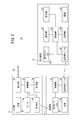
- FIG. 2 is a block diagram of the measurement system 10.
- the sensor unit 12 includes a needle 18, a measurement unit 30, a control unit 32, a storage unit 34, an RFID tag 36, a speaker 38, and a battery 40.
- the measuring unit 30 measures the concentration of the predetermined component contained in the body fluid sent from the needle 18.
- the measurement unit 30 will be described as measuring a blood glucose level.
- the measurement unit 30 detects a signal corresponding to the glucose concentration.
- the measurement unit 30 includes a light receiving element such as a photodiode, a light emitting element such as a light emitting diode, an indicator layer, and the like.
- the indicator layer includes a fluorescent dye (such as a phenylboronic acid derivative having a fluorescent residue) as a labeling compound, and the labeling compound captures glucose introduced by the needle 18.
- the indicator layer When the light emitting element is caused to emit light and light is incident on the indicator layer, the indicator layer obtains fluorescence having an intensity corresponding to the glucose concentration.
- the fluorescence from the indicator layer is photoelectrically converted by the light receiving element, and a light reception signal is sent to the control unit 32.
- the control unit 32 includes a CPU and a memory (not shown), and controls the entire sensor unit 12.
- the control unit 32 converts the light reception signal sent from the measurement unit 30 into a digital signal, and calculates a glucose concentration value (hereinafter referred to as a blood glucose level) based on the converted light reception signal of the digital signal.
- the control unit 32 stores the information on the calculated blood glucose level in the storage unit 34.
- the control unit 32 reads the sound data stored in the storage unit 34 and reads the speaker (
- the sound output means) 38 outputs a sound such as an alarm sound (warning sound).
- the speaker 38 functions as a notification unit that notifies that the blood sugar level is within the alarm region.
- the control unit 32 generates a trend indicating a fluctuation tendency of the blood glucose level over a predetermined time width based on the stored plurality of blood glucose levels, and stores the generated blood glucose level trend information in the storage unit 34.
- the RFID tag 36 as an IC tag has an antenna and an IC chip (not shown), and the control unit 32 reads blood glucose level or trend information stored in the storage unit 34 and uses the RFID tag 36 to read from the antenna. Send.
- the battery 40 may be a primary battery or a secondary battery.
- an IC tag such as an RFID tag is used as the proximity communication means.
- a non-contact IC card such as FeliCa (registered trademark) or a contact IC card may be used as the proximity communication means. .
- the transmission unit 14 includes an RFID reader / writer 50, a control unit 52, a transmission / reception module 54, and a battery 56.
- the RFID reader / writer 50 as a near field communication means transmits the command information by generating an electromagnetic field carrying the command information.
- the command information transmitted by the RFID reader / writer 50 includes information for instructing transmission of the latest measured blood glucose level, information for instructing transmission of a blood glucose level trend, and the like.
- the RFID tag 36 is activated by the electromagnetic field generated by the RFID reader / writer 50 and transmits information corresponding to the command information, and the RFID reader / writer 50 receives (reads) the information transmitted by the RFID tag 36.
- the control unit 52 includes a CPU and a memory (not shown), and controls the entire transmission unit 14.
- the control unit 52 wirelessly transmits information received by the RFID reader / writer 50 from the transmission / reception module 54 to the display device 16.
- the RFID reader / writer 50, the control unit 52, and the transmission / reception module 54 are driven using the power of the battery 56. Therefore, since the transmission unit 14 has a communication function with high power consumption, the capacity of the battery 56 is larger than that of the battery 40, and the transmission unit 14 is enlarged.
- the battery 56 may be a primary battery or a secondary battery.
- the display device 16 includes a transmission / reception module 60, a control unit 62, a storage unit 64, an RFID reader / writer 66, and a power source 68 in addition to the display unit 20 and the operation unit 22.
- the transmission / reception module 60 wirelessly receives blood glucose level or blood glucose level trend information wirelessly transmitted from the transmission / reception module 54 of the transmission unit 14.
- the transmission / reception module 54 and the transmission / reception module 60 exchange information with each other by wireless communication, and perform communication using, for example, Bluetooth, IrDA (Infrared Data Association) or the like.
- the control unit 62 controls the entire display device 16, and displays the blood glucose level or the blood glucose level trend wirelessly received by the transmission / reception module 60 on the display unit 20 or stores it in the storage unit 64. In addition, the control unit 62 switches the content displayed on the display unit 20 according to the operation of the operation unit 22, and stores the input information in the storage unit 64.
- the RFID reader / writer 66 as a proximity communication means has the same function as the RFID reader / writer 50 of the transmission unit 14. Thereby, the display device 16 can acquire information such as a blood glucose level directly from the RFID tag 36.
- the display unit 20, the transmission / reception module 60, the control unit 62, the storage unit 64, and the RFID reader / writer 66 are driven using the power of the power source 68.
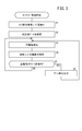
- step S1 the subject wears the sensor unit 12 on the upper arm 17 or the abdomen and turns on the power. Specifically, the needle 18 is punctured into the skin such as the upper arm portion 17 or the abdomen, and the sensor unit 12 is attached to the skin with the skin adhesive tape. Then, a power switch (not shown) provided in the sensor unit 12 is turned on, or a sheet that cuts off the electrical connection between the battery 40 and the control unit 32 is pulled to turn on the power of the sensor unit 12.
- the control unit 32 records calibration value data (step S2). Specifically, first, the subject inputs a blood glucose level obtained by self blood glucose measurement (SMBG) by operating the operation unit 22 of the display device 16.
- the display device 16 transmits the input blood glucose level information to the sensor unit 12 using the RFID reader / writer 66 or to the transmission unit 14 using the transmission / reception module 60.
- the sensor unit 12 may acquire the blood glucose level information directly from the display device 16 or indirectly through the transmission unit 14.
- the control unit 32 drives the measurement unit 30 to acquire a light reception signal corresponding to the glucose concentration from the measurement unit 30, and generates a blood glucose level acquired from the display device 16 and calibration value data from the light reception signal.
- the generated calibration value data is stored in the storage unit 34.
- the control unit 32 may acquire the calibration value data directly from the outside (the display device 16 or the like) and store it in the storage unit 34.
- the control unit 32 measures the blood sugar level (step S3). Specifically, the control unit 32 drives the measurement unit 30, acquires a light reception signal corresponding to the glucose concentration from the measurement unit 30, and calculates a blood glucose level based on the acquired light reception signal.
- the blood glucose level is calculated using the calibration value data stored in step S2. This blood glucose level is measured every predetermined cycle.
- control unit 32 stores the blood glucose level measured in step S3 in the storage unit 34 (step S4).
- control part 32 may update the trend of the blood glucose level memorize
- the control unit 32 determines whether or not the blood glucose level measured in step S3 is within the alarm region (step S5).
- the alarm region is a region that indicates a range of blood sugar levels that are not normal values. (In the case of hyperglycemia) is an alarm area.
- step S5 If it is determined in step S5 that the measured blood glucose level is not within the alarm region, the process directly returns to step S3. If it is determined that the measured blood glucose level is within the alarm region, the control unit 32 outputs an alarm sound from the speaker 38. (Step S6), the process returns to step S3.
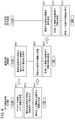
- step SB11 the RFID reader / writer 66 of the transmission unit 14 generates an electromagnetic field on which command information for instructing transmission of the latest blood glucose level is placed according to the control of the control unit 52.
- the generation of the electromagnetic field is performed at regular intervals.
- This constant cycle may be the same cycle as the blood glucose level measurement cycle (predetermined cycle) or may be a longer cycle.
- the RFID tag 36 of the sensor unit 12 is activated upon detection of an electromagnetic field generated by the RFID reader / writer 50, and receives command information instructing transmission of the latest blood glucose level (step SA11).
- control unit 32 of the sensor unit 12 reads the latest blood glucose level information from the storage unit 34 (step SA12) and transmits it using the RFID tag 36 (step SA13).
- the RFID reader / writer 50 of the transmission unit 14 receives information corresponding to the command information from the RFID tag 36, that is, the latest blood glucose level information (step SB12).
- the control unit 52 of the transmission unit 14 wirelessly transmits the received latest blood glucose level information from the transmission / reception module 54 (step SB13).
- the transmission / reception module 60 of the display device 16 wirelessly receives the latest blood glucose level information sent from the transmission unit 14 (step SC11).
- the control unit 62 of the display device 16 stores the received latest blood glucose level information in the storage unit 64 (step SC12).
- the control unit 62 of the display device 16 displays the received latest blood glucose level on the display unit 20 (step SC13).
- the transmission unit 14 When the subject wants to display the blood sugar level trend, he / she operates the operation unit 22 of the display device 16 to transmit information requesting the blood sugar level trend from the transmission / reception module 60 of the display device 16. To do. Upon receiving this information, the transmission unit 14 generates an electromagnetic field carrying command information for instructing transmission of a blood glucose level trend. As a result, blood glucose level trend information is transmitted from the RFID tag 36 to the transmission unit 14, and the transmission unit 14 transmits the received blood glucose level trend information to the display device 16. Are displayed on the display unit 20.
- the display device 16 may store the acquired trend information in the storage unit 64.
- the control unit 62 of the display device 16 generates a trend indicating the fluctuation tendency of the blood glucose level over a certain period of time using the plurality of blood glucose levels stored in the storage unit 64 and displays the trend on the display unit 20. Also good.
- the display device 16 acquires blood glucose level information and blood glucose level trend information from the sensor unit 12 via the transmission unit 14.
- the blood glucose level information and the blood glucose level trend information may be directly acquired from the unit 12.
- FIG. 5 is a flowchart illustrating an example of the operation of the measurement system 10 when the display device 16 directly acquires information from the sensor unit 12.
- the transmission unit 14 is not attached to the sensor unit 12, and the sensor unit 12 and the display device 16 constitute the measurement system 10.
- step SC21 when the user wants to see the latest measured blood glucose level or blood glucose level trend, he / she operates the operation unit 22 of the display device 16 to instruct display of the latest blood glucose level or blood glucose level trend (
- step SC22 the RFID reader / writer 66 of the display device 16 generates an electromagnetic field on which command information corresponding to the instruction is placed according to the control of the control unit 62 (step SC22).
- step SC22 the user brings the display device 16 close to the sensor unit 12.
- the RFID tag 36 of the sensor unit 12 is activated by detecting the electromagnetic field generated by the RFID reader / writer 66, and receives command information (step SA21).
- the control unit 32 of the sensor unit 12 reads information corresponding to the command information received from the RFID tag 36 from the storage unit 34 (step SA22).
- the command information is command information for instructing transmission of the latest blood glucose level
- the control unit 32 reads out information on the latest blood glucose level from the storage unit 34, and the command information indicates command transmission for instructing transmission of a blood glucose level trend.
- blood glucose trend information is read from the storage unit 34.
- control unit 32 transmits the read information using the RFID tag 36 (step SA23).
- the RFID reader / writer 66 of the display device 16 receives information corresponding to the command information from the RFID tag 36 (Step SC23), and the control unit 62 of the display device 16 displays the received information on the display unit 20 (Step S23). SC24). For example, when the received information is information on the latest blood sugar level, the latest blood sugar level is displayed on the display unit 20, and when the received information is information on the blood sugar level trend, the blood sugar level trend is displayed. Note that the control unit 62 may store the received information in the storage unit 64.
- the sensor unit 12 includes the storage unit 34 that stores blood glucose level information and the speaker 38 that outputs an alarm sound when the blood glucose level is within the alarm region.
- the continuous blood glucose monitor can be performed only by placing only the sensor unit 12 that is not provided on the skin of the subject, and the sensor unit 12 placed on the skin can be reduced in size and weight.
- the sensor unit 12 When the blood glucose level is within the alarm region, the sensor unit 12 outputs an alarm sound from the speaker 38. Therefore, even if the blood glucose level information is not transmitted to the display device 16, the user such as the subject can monitor the blood glucose level. It can be recognized that the value is not within the normal value range, and blood glucose control can be performed.
- the sensor unit 12 transmits blood glucose level information and the like using the RFID tag 36 as a proximity communication unit that performs proximity communication with lower power consumption than wireless communication with a communication distance of several tens of centimeters or more.
- the battery 40 mounted on the sensor can be reduced in size, and the sensor unit 12 can be reduced in size and weight.
- control unit 32 of the sensor unit 12 When the control unit 32 of the sensor unit 12 receives command information instructing transmission of information such as a blood glucose level, the control unit 32 reads information such as a blood glucose level corresponding to the command information from the storage unit 34 and uses the RFID tag 36. Therefore, the user can know the blood sugar level measured by the sensor unit 12.
- the user when the user wants to know information on the blood glucose level constantly, the user can know the latest measured blood glucose level via the display device 16 by attaching the transmission unit 14 to the sensor unit 12.
- the display device 16 can directly acquire information such as blood glucose level from the sensor unit 12. Further, since the display device 16 transmits command information instructing transmission of information such as blood glucose level according to the operation of the operation unit 22 by the user, the user can know information such as blood glucose level when he / she wants to know. .
- control unit 32 reads the blood glucose level information in response to the reception of the command information from the storage unit 34 and transmits it from the RFID tag 36, and then deletes the transmitted blood glucose level information from the storage unit 34. Good. Thereby, unnecessary information can be deleted from the storage unit 34, the storage unit 34 can be used effectively, and the capacity of the storage unit 34 can be reduced.
- the speaker 38 was employ
- step SC21 in FIG. 5 the user may instruct the display of a plurality of blood glucose levels that have been measured so far and have not been received by the display device 16.
- the RFID reader / writer 66 generates an electromagnetic field on which command information stored in the storage unit 34 of the sensor unit 12 and instructing transmission of a plurality of blood glucose levels not yet transmitted is placed. Also good.
- the display device 16 can acquire information on a plurality of blood glucose levels that have already been measured and have not been received.
- the sensor unit 12 includes the speaker 38 as a notification unit, but may include a light emitting unit having a light emitting element such as an LED that emits light, and the light emitting unit may be used as the notification unit. That is, when the measured blood glucose level is within the alarm region, the control unit 32 notifies the fact that the blood glucose level is within the alarm region by causing the light emitting means to emit light.
Landscapes
- Health & Medical Sciences (AREA)
- Life Sciences & Earth Sciences (AREA)
- Physics & Mathematics (AREA)
- Biomedical Technology (AREA)
- Medical Informatics (AREA)
- Biophysics (AREA)
- Pathology (AREA)
- Engineering & Computer Science (AREA)
- Veterinary Medicine (AREA)
- Heart & Thoracic Surgery (AREA)
- Optics & Photonics (AREA)
- Molecular Biology (AREA)
- Surgery (AREA)
- Animal Behavior & Ethology (AREA)
- General Health & Medical Sciences (AREA)
- Public Health (AREA)
- Emergency Medicine (AREA)
- Spectroscopy & Molecular Physics (AREA)
- Measurement Of The Respiration, Hearing Ability, Form, And Blood Characteristics Of Living Organisms (AREA)
Description
本発明は、被検者の体液中の所定成分を連続的に測定するセンサ部及び該センサ部を有する測定システムに関する。
近年、センサ部が設けられた専用の針を皮膚に穿刺することで、該針を皮下に留置し、被検者の血糖値を連続的にモニタリングする持続血糖モニタ(Continuous Glucose Monitoring : CGM)に用いる測定システムが実用化されている。
例えば、特開2011-212117号公報には、血糖を測定するセンサ部が測定した測定信号をRFIDによって受信し、該受信した測定信号から血糖値を求めて表示部に送信する送信部を、センサ部に着脱可能に取り付けることで、防水性を向上させた持続血糖モニタに用いる体液成分測定システムが記載されている。
特開2011-212117号公報の記載の体液成分測定システムでは、持続血糖モニタを行う際には、センサ部と、該センサ部の検出結果に基づく測定値を表示部に無線送信する送信部とが必須の構成となるため、送信部が取り付けられたセンサ部を被検者の皮膚に常時留置しなければならず、センサ部及び送信部の小型化、軽量化が望まれる。
しかしながら、送信機能は大きな電力を必要とするため、容量の大きい電池を用いなければならず、それにより、送信部が大型化、重量化してしまう。
本発明は、係る従来の問題点に鑑みてなされたものであり、消費電力が大きい送信機能が無くても持続血糖モニタを行うことができるセンサ部及び測定システムを提供することを目的とする。
上記目的を達成するために、本発明は、被検者の皮膚に留置され、被検者の体液に導通されて体液の所定成分の濃度を測定するセンサ部であって、前記センサ部は、前記体液の所定成分の濃度に応じた信号を検出する測定部と、前記センサ部を制御する制御部と、記憶部と、報知部と、近接通信手段と、を備え、前記制御部は、前記測定部が検出した前記体液の所定成分の濃度に応じた信号に基づいて濃度値を算出し、該濃度値の情報を前記記憶部に記憶すると共に、濃度値が報知領域内にある場合は、前記報知部にその旨を報知させ、前記近接通信手段は、前記濃度値の情報の送信を指示するコマンド情報を受信した場合に、前記記憶部に記憶されている該濃度値の情報を送信することを特徴とする。
上記の構成によれば、前記センサ部は、測定した前記濃度値を記憶する前記記憶部と、前記濃度値が前記報知領域内にある場合はその旨を報知する報知部とを備えるので、消費電力の大きい送信機能を有しない前記センサ部のみを被検者の皮膚に留置させるだけで、連続して前記濃度値をモニタリングすることができ、皮膚に留置させる前記センサ部を小型化、軽量化することができる。
また、前記センサ部は、前記濃度値が前記報知領域内にある場合は、その旨を報知するので、ユーザは、前記濃度値が正常値の範囲内にないことを認識することできる。更に、前記近接通信手段は、前記コマンド情報を受信した場合に、該コマンド情報に対応する前記濃度値の情報を前記記憶部から読み出して送信するので、ユーザは、前記センサ部が測定した濃度値を知ることができる。
前記センサ部であって、前記センサ部の前記近接通信手段は、RFIDタグであることを特徴とする。前記RFIDタグは、通信距離が数十cm以上の無線通信に比べて消費電力が小さい近接通信を行うので、前記センサ部に搭載する電池の容量を抑えることができ、前記センサ部内に設ける電池の容量を小さくすることができる。
前記測定システムであって、前記センサ部の前記近接通信手段の相手となって、前記コマンド情報の送信、及び前記濃度値の情報の受信を行う近接通信手段を有し、受信した濃度値の情報を表示する表示装置を備え、前記表示装置の前記近接通信手段は、ユーザによって前記濃度値の表示の指示があった場合に、前記コマンド情報を前記センサ部に送信することを特徴とする。
上記構成によれば、ユーザの操作に応じて前記表示装置が前記センサ部から濃度値を直接取得することができるので、電池の容量が大きくなる送信部をセンサ部に取り付けなくても、ユーザが前記濃度値を知りたい時に該濃度値を表示することができる。
前記測定システムであって、前記表示装置の前記近接通信手段は、RFIDリーダライタであることを特徴とする。
前記測定システムであって、前記センサ部に着脱可能な送信部と、前記濃度値を表示する表示装置とを備え、前記送信部は、前記センサ部の前記近接通信手段の相手となって、一定周期での前記コマンド情報の送信、及び前記濃度値の情報の受信を行う近接通信手段と、前記表示装置と無線通信して、受信した前記濃度値の情報を送信する送受信モジュールと、を有することを特徴とする。
上記構成によれば、一定周期で前記濃度値の情報を取得して前記表示装置に送信する前記送信部を、前記センサ部に取り付けることで、前記センサ部が測定した濃度値を、リアルタイムに知ることができ、該濃度値の変化を見ることができる。
前記測定システムであって、前記送信部の前記近接通信手段は、RFIDリーダライタであることを特徴とする。
前記測定システムであって、前記制御部は、前記コマンド情報の受信に応じて前記近接通信手段が送信した前記濃度値の情報を前記記憶部から削除することを特徴とする。この構成により、不必要となった情報を前記記憶部から削除するので、前記記憶部を有効活用することができ、該記憶部の容量を小さくすることも可能となる。
前記測定システムであって、前記報知部は、音声出力手段又は発光手段であることを特徴とする。
本発明によれば、センサ部は、測定した濃度値を記憶する記憶部と、濃度値が報知領域内にある場合はその旨を報知する報知部とを備えるので、消費電力の大きい送信機能を有しないセンサ部のみを被検者の皮膚に留置させるだけで、持続して濃度値をモニタリングすることができ、皮膚に留置させるセンサ部を小型化、軽量化することができる。
また、センサ部は、濃度値が報知領域内にある場合は、その旨を報知するので、ユーザは、濃度値が正常値の範囲内にないことを認識することできる。更に、センサ部は、近接通信手段を通じてコマンド情報を受信した場合に、該コマンド情報に対応する濃度値の情報を記憶部から読み出して送信するので、ユーザは、センサ部が測定した濃度値を知ることができる。
本発明に係るセンサ部及びセンサ部を有する測定システムについて、好適な実施の形態を掲げ、添付の図面を参照しながら以下、詳細に説明する。
図1は、実施の形態にかかる測定システム10の外観図である。測定システム10は、センサ部12と、送信部14と、表示装置16とを有する。
センサ部12は、被検者の皮膚に留置され、被検者の体液に導通された被検者の体液の所定成分(例えば、グルコース、尿酸、コレステロール、タンパク質、ミネラル、血液細胞等)の濃度を測定する。センサ部12の筐体12aは、樹脂部材等によって形成されており、筐体12aの底面には、被検者の上腕部17等の皮膚に穿刺され、皮下の体液(血液、間質液、リンパ液等)に接触する針18と、図示しない皮膚貼付テープが設けられている。この針18は、センサ部12の測定部30(図2参照)内に体液が届くように誘導する毛細管である。なお、針18の先端に測定部30が設けられたものであってもよい。
送信部14は、センサ部12に着脱可能に取り付け可能であり、センサ部12が測定した所定成分の濃度値(測定値)等を表示装置16に無線送信する。送信部14の筐体14aは、樹脂部材等によって形成されている。表示装置16は、送信部14から送られてきた濃度値等を表示する表示部20と、表示部20の表示内容の切り替え、所定情報の入力等の各種操作をユーザ(被検者等)が行うための操作部22とを有する。
図2は、測定システム10のブロック図である。センサ部12は、針18、測定部30、制御部32、記憶部34、RFIDタグ36、スピーカ38、及び電池40を有する。
測定部30は、針18から送られてきた体液に含まれる所定成分の濃度を測定する。本実施の形態では、測定部30は、血糖値を測定するものとして説明する。測定部30は、グルコースの濃度に応じた信号を検出する。詳しくは、測定部30は、図示しないが、フォトダイオード等の受光素子、発光ダイオード等の発光素子、及びインジケータ層等を有する。インジケータ層は、標識化合物としての蛍光色素(蛍光残基を有するフェニルボロン酸誘導体等)を含んでおり、該標識化合物は、針18によって導入されたグルコースを捕捉する。前記発光素子を発光させて、インジケータ層に光を入射させると、インジケータ層は、グルコースの濃度に応じた強度の蛍光を得る。このインジケータ層からの蛍光は受光素子によって光電変換され、受光信号が制御部32に送られる。
制御部32は、図示しないCPU及びメモリ等を有し、センサ部12全体を制御する。制御部32は、測定部30から送られてきた受光信号をデジタル信号に変換すると共に、該変換したデジタル信号の受光信号に基づいてグルコースの濃度値(以下、血糖値という)を算出する。制御部32は、算出した血糖値の情報を記憶部34に記憶すると共に、算出した血糖値がアラーム(報知)領域内の場合は、記憶部34に記憶された音データを読み出して、スピーカ(音声出力手段)38からアラーム音(警告音)等の音を出力する。このスピーカ38は、血糖値がアラーム領域内にある旨を報知する報知部として機能する。また、制御部32は、記憶した複数の血糖値に基づいて、一定時間幅における血糖値の変動傾向を示すトレンドを生成し、該生成した血糖値のトレンドの情報を記憶部34に記憶する。
ICタグとしてのRFIDタグ36は、図示しないアンテナ及びICチップを有し、制御部32は、記憶部34に記憶されている血糖値又はトレンドの情報を読み出し、RFIDタグ36を用いて前記アンテナから送信する。
なお、RFIDタグ36は近接無線通信を行うため、通信距離が数十cm以上の無線通信に比べて消費電力が小さい。従って、センサ部12は消費電力の大きい通信機能を有さないので、電池40の容量を小さくすることができ、センサ部12を小型化することができる。この電池40は、一次電池であってもよく、二次電池であってもよい。また、本実施の形態では近接通信手段としてRFIDタグ等のICタグを用いたが、近接通信手段としてFeliCa(登録商標)等の非接触式ICカードや、接触式ICカードを採用してもよい。
送信部14は、RFIDリーダライタ50、制御部52、送受信モジュール54、及び電池56を有する。近接通信手段としてのRFIDリーダライタ50は、コマンド情報を乗せた電磁界を発生することで、該コマンド情報を送信する。RFIDリーダライタ50が送信するコマンド情報としては、測定した最新の血糖値の送信を指示する情報や、血糖値のトレンドの送信を指示する情報等がある。
ここで、RFIDタグ36は、RFIDリーダライタ50が発生した電磁界によって起動してコマンド情報に対応する情報を送信し、RFIDリーダライタ50はRFIDタグ36が送信した情報を受信する(読み取る)。
制御部52は、図示しないCPU及びメモリ等を有し、送信部14全体を制御する。制御部52は、RFIDリーダライタ50が受信した情報を送受信モジュール54から表示装置16に無線送信させる。RFIDリーダライタ50、制御部52、及び送受信モジュール54は、電池56の電力を用いて駆動する。従って、送信部14は、消費電力の大きい通信機能を有するので、電池56の容量は電池40より大きくなり、送信部14が大型化する。電池56は、一次電池であってもよく、二次電池であってもよい。
表示装置16は、表示部20及び操作部22の他に、送受信モジュール60、制御部62、記憶部64、RFIDリーダライタ66、及び電源68を備える。送受信モジュール60は、送信部14の送受信モジュール54から無線送信された血糖値又は血糖値のトレンドの情報を無線受信する。送受信モジュール54及び送受信モジュール60は、互いに無線通信により情報を授受するものであり、例えば、Bluetooth、IrDA(Infrared Data Association)等を用いて通信を行う。
制御部62は、表示装置16全体を制御するものであり、送受信モジュール60が無線受信した血糖値又は血糖値のトレンドを表示部20に表示したり、記憶部64に記憶する。また、制御部62は、操作部22の操作に応じて表示部20に表示する内容を切り替えたり、入力された情報を記憶部64に記憶する。
近接通信手段としてのRFIDリーダライタ66は、送信部14のRFIDリーダライタ50と同様の機能を有する。これにより、表示装置16が、RFIDタグ36から直接血糖値等の情報を取得することができる。表示部20、送受信モジュール60、制御部62、記憶部64、及びRFIDリーダライタ66は、電源68の電力を用いて駆動する。
次に、センサ部12のモニタリング処理の動作を図3のフローチャートに従って説明する。まず、ステップS1では、被検者がセンサ部12を上腕部17又は腹部に装着して電源をオンにする。詳しくは、針18を上腕部17又は腹部等の皮膚に穿刺すると共に、前記皮膚貼付テープによりセンサ部12を皮膚に貼り付ける。そして、センサ部12に設けられた図示しない電源スイッチをオン、又は、電池40と制御部32との電気的な接続を遮断するシートを引っ張ることで、センサ部12の電源をオンにする。
次いで、制御部32は、校正値データを記録する(ステップS2)。詳しくは、先ず被検者が自己血糖測定(SMBG)によって得られた血糖値を表示装置16の操作部22を操作することで入力する。表示装置16は、該入力された血糖値の情報を、RFIDリーダライタ66を用いてセンサ部12へ送信、又は、送受信モジュール60を用いて送信部14へ送信する。センサ部12は、該血糖値の情報を表示装置16から直接取得してもよいし、送信部14を介して間接的に取得してもよい。また、制御部32は、測定部30を駆動させて、グルコースの濃度に応じた受光信号を測定部30から取得し、表示装置16から取得した血糖値と、該受光信号から校正値データを生成し、該生成した校正値データを記憶部34に記憶する。なお、制御部32は、外部(表示装置16等)から直接校正値データを取得して記憶部34に記憶してもよい。
次いで、制御部32は、血糖値の測定を行う(ステップS3)。詳しくは、制御部32は、測定部30を駆動させて、グルコースの濃度に応じた受光信号を測定部30から取得し、該取得した受光信号に基づいて血糖値を算出する。血糖値を算出する際には、ステップS2で記憶した校正値データを用いて血糖値を算出する。この血糖値の測定は、所定周期毎に行う。
次いで、制御部32は、ステップS3で測定した血糖値を記憶部34に記憶する(ステップS4)。なお、制御部32は、ステップS3で測定した血糖値を用いて記憶部34に記憶されている血糖値のトレンドを更新してもよい。
次いで、制御部32は、ステップS3で測定した血糖値がアラーム領域内にあるか否かを判断する(ステップS5)。アラーム領域とは、正常値でない血糖値の範囲を示す領域であり、血糖値が第1閾値以下の場合(低血糖の場合)、又は、血糖値が第1閾値より大きい第2閾値以上の場合(高血糖の場合)は、アラーム領域となる。
ステップS5で、測定した血糖値がアラーム領域内にないと判断するとそのままステップS3に戻り、測定した血糖値がアラーム領域内にあると判断すると、制御部32は、スピーカ38からアラーム音を出力して(ステップS6)、ステップS3に戻る。
次に、表示装置16が送信部14を介してセンサ部12から情報を取得して表示する場合の測定システム10の動作の一例を図4のフローチャートに従って説明する。なお、送信部14は、センサ部12に取り付けられているものとする。
まず、ステップSB11で、送信部14のRFIDリーダライタ66は、制御部52の制御に従って最新の血糖値の送信を指示するコマンド情報を乗せた電磁界を発生する。この電磁界の発生は、一定周期毎に行う。この一定周期は、血糖値の測定周期(所定周期)と同じ周期であってもよく、それよりも長い周期であってもよい。
センサ部12のRFIDタグ36は、RFIDリーダライタ50が発生した電磁界の検出により起動し、最新の血糖値の送信を指示するコマンド情報を受信する(ステップSA11)。
次いで、センサ部12の制御部32は、最新の血糖値の情報を記憶部34から読み出し(ステップSA12)、RFIDタグ36を用いて送信する(ステップSA13)。
送信部14のRFIDリーダライタ50は、RFIDタグ36からコマンド情報に対応する情報、つまり、最新の血糖値の情報を受信する(ステップSB12)。次いで、送信部14の制御部52は、受信した最新の血糖値の情報を送受信モジュール54から無線送信する(ステップSB13)。
表示装置16の送受信モジュール60は、送信部14から送られてきた最新の血糖値の情報を無線受信する(ステップSC11)。次いで、表示装置16の制御部62は、受信した最新の血糖値の情報を記憶部64に記憶する(ステップSC12)。次いで、表示装置16の制御部62は、該受信した最新の血糖値を表示部20に表示する(ステップSC13)。
なお、被検者は、血糖値のトレンドを表示させたい場合は、表示装置16の操作部22を操作することで、表示装置16の送受信モジュール60から、血糖値のトレンドを要求する情報を送信する。この情報を受け取った送信部14は、血糖値のトレンドの送信を指示するコマンド情報を乗せた電磁界を発生する。これにより、RFIDタグ36から血糖値のトレンドの情報が送信部14に送られ、送信部14は、該受信した血糖値のトレンドの情報を表示装置16に送信し、表示装置16は、血糖値のトレンドを表示部20に表示する。また、表示装置16は、該取得したトレンドの情報を記憶部64に記憶してもよい。また、表示装置16の制御部62は、記憶部64に記憶している複数の血糖値を用いて、一定時間幅における血糖値の変動傾向を示すトレンドを生成して表示部20に表示してもよい。
図4のフローチャートに示す動作では、表示装置16は、送信部14を介して、センサ部12から血糖値の情報及び血糖値のトレンドの情報を取得するようにしたが、表示装置16は、センサ部12から血糖値の情報及び血糖値のトレンドの情報を直接取得するようにしてもよい。
図5は、表示装置16がセンサ部12から情報を直接取得する場合の測定システム10の動作の一例を示すフローチャートである。なお、この場合は、送信部14は、センサ部12に取り付けられていないものとし、センサ部12と表示装置16とで測定システム10を構成する。
まず、ユーザは、測定された最新の血糖値又は血糖値のトレンドを見たい場合は、表示装置16の操作部22を操作して、最新の血糖値又は血糖値のトレンドの表示を指示すると(ステップSC21)、表示装置16のRFIDリーダライタ66は、制御部62の制御に従って指示に応じたコマンド情報を乗せた電磁界を発生する(ステップSC22)。なお、このとき、ユーザは、表示装置16をセンサ部12に近接させる。
センサ部12のRFIDタグ36は、RFIDリーダライタ66が発生した電磁界を検出して起動し、コマンド情報を受信する(ステップSA21)。
次いで、センサ部12の制御部32は、RFIDタグ36から受信したコマンド情報に応じた情報を記憶部34から読み出す(ステップSA22)。制御部32は、コマンド情報が最新の血糖値の送信を指示するコマンド情報の場合は、記憶部34から最新の血糖値の情報を読み出し、コマンド情報が血糖値のトレンドの送信を指示するコマンド情報の場合は、記憶部34から血糖値のトレンドの情報を読み出す。
次いで、制御部32は、RFIDタグ36を用いて、該読み出した情報を送信する(ステップSA23)。
表示装置16のRFIDリーダライタ66は、RFIDタグ36からコマンド情報に対応する情報を受信し(ステップSC23)、表示装置16の制御部62は、該受信した情報を表示部20に表示する(ステップSC24)。例えば、受信した情報が最新の血糖値の情報の場合は、最新の血糖値を表示部20に表示し、受信した情報が血糖値のトレンドの情報の場合は、血糖値のトレンドを表示する。なお、制御部62は、受信した情報を記憶部64に記憶してもよい。
このように、センサ部12は、血糖値の情報を記憶する記憶部34と、血糖値がアラーム領域内にある場合はアラーム音を出力するスピーカ38とを備えるので、消費電力の大きい送信機能を有しないセンサ部12のみを被検者の皮膚に留置させるだけで、持続血糖モニタを行うことができ、皮膚に留置させるセンサ部12を小型化、軽量化することができる。
センサ部12は、血糖値がアラーム領域内にある場合は、アラーム音をスピーカ38から出力するので、表示装置16に血糖値の情報を送信しなくても、被検者等のユーザは、血糖値が正常値の範囲内にないことを認識することでき、血糖コントロールを行うことができる。
センサ部12は、通信距離が数十cm以上の無線通信に比べて消費電力が小さい近接通信を行う近接通信手段としてのRFIDタグ36を用いて血糖値の情報等を送信するので、センサ部12に搭載する電池40を小型化することができ、センサ部12を小型化、軽量化することができる。
センサ部12の制御部32は、血糖値等の情報の送信を指示するコマンド情報を受信した場合に、該コマンド情報に対応する血糖値等の情報を記憶部34から読み出し、RFIDタグ36を用いて送信するので、ユーザは、センサ部12が測定した血糖値等を知ることができる。
また、常時血糖値の情報をユーザが知りたい場合は、センサ部12に送信部14を取り付けることで、測定した最新の血糖値をユーザは表示装置16を介して知ることができる。
また、表示装置16にRFIDタグ36の情報を取得するRFIDリーダライタ66を設けるようにしたので、表示装置16がセンサ部12から血糖値等の情報を直接取得することができる。また、表示装置16は、ユーザの操作部22の操作に応じて血糖値等の情報の送信を指示するコマンド情報を送信するので、ユーザは、知りたい時に血糖値等の情報を知ることができる。
なお、制御部32は、コマンド情報の受信に応じた血糖値の情報を記憶部34から読み出して、RFIDタグ36から送信した後、該送信した血糖値の情報を記憶部34から削除してもよい。これにより、不必要となった情報を記憶部34から削除することができ、記憶部34を有効活用できると共に、記憶部34の容量を小さくすることも可能となる。また、報知部としてスピーカ38を採用したが、光を発光する発光装置を採用してもよい。
また、図5ステップSC21では、ユーザは、今までに測定され表示装置16が受信していない複数の血糖値の表示を指示してもよい。この場合は、ステップSC22で、RFIDリーダライタ66は、センサ部12の記憶部34に記憶され、未だ送信していない複数の血糖値の送信を指示するコマンド情報を乗せた電磁界を発生してもよい。これより、表示装置16は、既に測定され未だ受信していない複数の血糖値の情報を取得することができる。
センサ部12は、報知部としてスピーカ38を有するようにしたが、光を発光するLED等の発光素子を有する発光手段を備え、該発光手段を報知部として用いてもよい。つまり、測定した血糖値がアラーム領域内にある場合は、制御部32は、発光手段により光を発光させることで、血糖値がアラーム領域内にある旨を報知する。
以上、本発明について好適な実施の形態を用いて説明したが、本発明の技術的範囲は上記実施の形態に記載の範囲には限定されない。上記実施の形態に、多様な変更又は改良を加えることが可能であることが当業者に明らかである。その様な変更又は改良を加えた形態も本発明の技術的範囲に含まれ得ることが、特許請求の範囲の記載から明らかである。
Claims (8)
- 被検者の皮膚に留置され、被検者の体液に導通されて体液の所定成分の濃度を測定するセンサ部(12)であって、
前記センサ部(12)は、前記体液の所定成分の濃度に応じた信号を検出する測定部(30)と、前記センサ部(12)を制御する制御部(32)と、記憶部(34)と、報知部(38)と、近接通信手段(36)と、を備え、
前記制御部(32)は、前記測定部(30)が検出した前記体液の所定成分の濃度に応じた信号に基づいて濃度値を算出し、該濃度値の情報を前記記憶部(34)に記憶すると共に、濃度値が報知領域内にある場合は、前記報知部(38)にその旨を報知させ、
前記近接通信手段(36)は、前記濃度値の情報の送信を指示するコマンド情報を受信した場合に、前記記憶部(34)に記憶されている該濃度値の情報を送信する
ことを特徴とするセンサ部(12)。 - 請求項1に記載のセンサ部(12)であって、
前記センサ部(12)の前記近接通信手段(36)は、RFIDタグである
ことを特徴とするセンサ部(12)。 - 請求項1に記載のセンサ部(12)を有する測定システム(10)であって、
前記センサ部(12)の前記近接通信手段(36)の相手となって、前記コマンド情報の送信、及び前記濃度値の情報の受信を行う近接通信手段(66)を有し、受信した濃度値の情報を表示する表示装置(16)を備え、
前記表示装置(16)の前記近接通信手段(66)は、ユーザによって前記濃度値の表示の指示があった場合に、前記コマンド情報を前記センサ部(12)に送信する
ことを特徴とする測定システム(10)。 - 請求項3に記載の測定システム(10)であって、
前記表示装置(16)の前記近接通信手段(66)は、RFIDリーダライタである
ことを特徴とする測定システム(10)。 - 請求項1に記載のセンサ部(12)を有する測定システム(10)であって、
前記センサ部(12)に着脱可能な送信部(14)と、前記濃度値を表示する表示装置(16)とを備え、
前記送信部(14)は、前記センサ部(12)の前記近接通信手段(36)の相手となって、一定周期での前記コマンド情報の送信、及び前記濃度値の情報の受信を行う近接通信手段(50)と、前記表示装置(16)と無線通信して、受信した前記濃度値の情報を送信する送受信モジュール(54)と、を有することを特徴とする測定システム(10)。 - 請求項5に記載の測定システム(10)であって、
前記送信部(14)の前記近接通信手段(50)は、RFIDリーダライタである
ことを特徴とする測定システム(10)。 - 請求項1に記載の測定システム(10)であって、
前記制御部(32)は、前記コマンド情報の受信に応じて前記近接通信手段(36)が送信した前記濃度値の情報を前記記憶部(34)から削除する
ことを特徴とする測定システム(10)。 - 請求項1に記載の測定システム(10)であって、
前記報知部(38)は、音声出力手段(38)又は発光手段である
ことを特徴とする測定システム(10)。
Priority Applications (1)
| Application Number | Priority Date | Filing Date | Title |
|---|---|---|---|
| PCT/JP2012/074446 WO2014045451A1 (ja) | 2012-09-24 | 2012-09-24 | センサ部及び測定システム |
Applications Claiming Priority (1)
| Application Number | Priority Date | Filing Date | Title |
|---|---|---|---|
| PCT/JP2012/074446 WO2014045451A1 (ja) | 2012-09-24 | 2012-09-24 | センサ部及び測定システム |
Publications (1)
| Publication Number | Publication Date |
|---|---|
| WO2014045451A1 true WO2014045451A1 (ja) | 2014-03-27 |
Family
ID=50340798
Family Applications (1)
| Application Number | Title | Priority Date | Filing Date |
|---|---|---|---|
| PCT/JP2012/074446 Ceased WO2014045451A1 (ja) | 2012-09-24 | 2012-09-24 | センサ部及び測定システム |
Country Status (1)
| Country | Link |
|---|---|
| WO (1) | WO2014045451A1 (ja) |
Citations (3)
| Publication number | Priority date | Publication date | Assignee | Title |
|---|---|---|---|---|
| WO2000047109A1 (en) * | 1999-02-12 | 2000-08-17 | Cygnus, Inc. | Devices and methods for frequent measurement of an analyte present in a biological system |
| JP2006289081A (ja) * | 2005-04-01 | 2006-10-26 | Codman & Shurtleff Inc | 患者を無線で監視するシステム |
| JP2011212117A (ja) * | 2010-03-31 | 2011-10-27 | Terumo Corp | 体液成分測定システム |
-
2012
- 2012-09-24 WO PCT/JP2012/074446 patent/WO2014045451A1/ja not_active Ceased
Patent Citations (3)
| Publication number | Priority date | Publication date | Assignee | Title |
|---|---|---|---|---|
| WO2000047109A1 (en) * | 1999-02-12 | 2000-08-17 | Cygnus, Inc. | Devices and methods for frequent measurement of an analyte present in a biological system |
| JP2006289081A (ja) * | 2005-04-01 | 2006-10-26 | Codman & Shurtleff Inc | 患者を無線で監視するシステム |
| JP2011212117A (ja) * | 2010-03-31 | 2011-10-27 | Terumo Corp | 体液成分測定システム |
Similar Documents
| Publication | Publication Date | Title |
|---|---|---|
| US12310693B2 (en) | Analyte sensor transceiver configured to provide tactile, visual, and/or aural feedback | |
| US10238289B2 (en) | Body fluid component measuring system | |
| CA2935565C (en) | Continuous analyte monitoring system | |
| US20140275876A1 (en) | Systems and methods for locating and/or identifying a wireless sensor associated with a patient monitor | |
| US20110191044A1 (en) | Interconnect for on-body analyte monitoring device | |
| US10016153B2 (en) | Photoplethysmographic measurement method and apparatus | |
| JP2016047154A (ja) | 生体情報計測装置 | |
| KR102173725B1 (ko) | 생체 신호를 측정하는 방법 및 장치 | |
| JP2003275183A (ja) | 生体情報検出センサ及びセンサ制御装置 | |
| EP3187108A1 (en) | Biological information measuring device | |
| JP6084568B2 (ja) | アナライトモニタシステム | |
| KR20220030089A (ko) | 생체정보 추정 장치 및 방법 | |
| JP2011212117A (ja) | 体液成分測定システム | |
| JP2016086873A (ja) | バイタルセンサモジュールおよびその動作方法 | |
| JP2011251007A (ja) | 生体脈波センサ及び生体脈波測定装置 | |
| EP3030150B1 (en) | Analyte sensor transceiver configured to provide tactile, and optionally visual and / or aural, feedback | |
| JP2011212118A (ja) | 体液成分測定システム | |
| US20140058222A1 (en) | Data transfer device and data transfer system | |
| JP7085866B2 (ja) | 医療機器システム | |
| US20190192014A1 (en) | Biological information measurement device | |
| CN110313920B (zh) | 生物体信息测定装置和生物体信息测定系统 | |
| JP2019170716A (ja) | 生体情報測定装置及び生体情報測定システム | |
| CA2918988C (en) | Analyte sensor transceiver configured to provide tactile, visual, and/or aural feedback | |
| KR20150109226A (ko) | 유연하며 신체 장착가능한 정보기기 |
Legal Events
| Date | Code | Title | Description |
|---|---|---|---|
| 121 | Ep: the epo has been informed by wipo that ep was designated in this application |
Ref document number: 12885058 Country of ref document: EP Kind code of ref document: A1 |
|
| NENP | Non-entry into the national phase |
Ref country code: DE |
|
| 122 | Ep: pct application non-entry in european phase |
Ref document number: 12885058 Country of ref document: EP Kind code of ref document: A1 |
|
| NENP | Non-entry into the national phase |
Ref country code: JP |