WO2014045321A1 - 情報処理装置、情報処理装置の制御方法、圧分布計測システム、および記憶媒体 - Google Patents
情報処理装置、情報処理装置の制御方法、圧分布計測システム、および記憶媒体 Download PDFInfo
- Publication number
- WO2014045321A1 WO2014045321A1 PCT/JP2012/006020 JP2012006020W WO2014045321A1 WO 2014045321 A1 WO2014045321 A1 WO 2014045321A1 JP 2012006020 W JP2012006020 W JP 2012006020W WO 2014045321 A1 WO2014045321 A1 WO 2014045321A1
- Authority
- WO
- WIPO (PCT)
- Prior art keywords
- pressure
- pressure distribution
- sensor
- information processing
- detection sensor
- Prior art date
- Legal status (The legal status is an assumption and is not a legal conclusion. Google has not performed a legal analysis and makes no representation as to the accuracy of the status listed.)
- Ceased
Links
Images







Classifications
-
- G—PHYSICS
- G01—MEASURING; TESTING
- G01L—MEASURING FORCE, STRESS, TORQUE, WORK, MECHANICAL POWER, MECHANICAL EFFICIENCY, OR FLUID PRESSURE
- G01L1/00—Measuring force or stress, in general
- G01L1/20—Measuring force or stress, in general by measuring variations in ohmic resistance of solid materials or of electrically-conductive fluids; by making use of electrokinetic cells, i.e. liquid-containing cells wherein an electrical potential is produced or varied upon the application of stress
- G01L1/205—Measuring force or stress, in general by measuring variations in ohmic resistance of solid materials or of electrically-conductive fluids; by making use of electrokinetic cells, i.e. liquid-containing cells wherein an electrical potential is produced or varied upon the application of stress using distributed sensing elements
-
- A—HUMAN NECESSITIES
- A61—MEDICAL OR VETERINARY SCIENCE; HYGIENE
- A61B—DIAGNOSIS; SURGERY; IDENTIFICATION
- A61B5/00—Measuring for diagnostic purposes; Identification of persons
- A61B5/103—Measuring devices for testing the shape, pattern, colour, size or movement of the body or parts thereof, for diagnostic purposes
- A61B5/1036—Measuring load distribution, e.g. podologic studies
- A61B5/1038—Measuring plantar pressure during gait
-
- A—HUMAN NECESSITIES
- A61—MEDICAL OR VETERINARY SCIENCE; HYGIENE
- A61B—DIAGNOSIS; SURGERY; IDENTIFICATION
- A61B5/00—Measuring for diagnostic purposes; Identification of persons
- A61B5/103—Measuring devices for testing the shape, pattern, colour, size or movement of the body or parts thereof, for diagnostic purposes
- A61B5/11—Measuring movement of the entire body or parts thereof, e.g. head or hand tremor or mobility of a limb
- A61B5/112—Gait analysis
-
- A—HUMAN NECESSITIES
- A61—MEDICAL OR VETERINARY SCIENCE; HYGIENE
- A61B—DIAGNOSIS; SURGERY; IDENTIFICATION
- A61B5/00—Measuring for diagnostic purposes; Identification of persons
- A61B5/68—Arrangements of detecting, measuring or recording means, e.g. sensors, in relation to patient
- A61B5/6887—Arrangements of detecting, measuring or recording means, e.g. sensors, in relation to patient mounted on external non-worn devices, e.g. non-medical devices
- A61B5/6892—Mats
-
- G—PHYSICS
- G01—MEASURING; TESTING
- G01G—WEIGHING
- G01G19/00—Weighing apparatus or methods adapted for special purposes not provided for in the preceding groups
- G01G19/44—Weighing apparatus or methods adapted for special purposes not provided for in the preceding groups for weighing persons
-
- A—HUMAN NECESSITIES
- A61—MEDICAL OR VETERINARY SCIENCE; HYGIENE
- A61B—DIAGNOSIS; SURGERY; IDENTIFICATION
- A61B2562/00—Details of sensors; Constructional details of sensor housings or probes; Accessories for sensors
- A61B2562/02—Details of sensors specially adapted for in-vivo measurements
- A61B2562/0247—Pressure sensors
-
- A—HUMAN NECESSITIES
- A61—MEDICAL OR VETERINARY SCIENCE; HYGIENE
- A61B—DIAGNOSIS; SURGERY; IDENTIFICATION
- A61B2562/00—Details of sensors; Constructional details of sensor housings or probes; Accessories for sensors
- A61B2562/16—Details of sensor housings or probes; Details of structural supports for sensors
- A61B2562/164—Details of sensor housings or probes; Details of structural supports for sensors the sensor is mounted in or on a conformable substrate or carrier
Definitions
- the present invention relates to an information processing device, a control method for the information processing device, a pressure distribution measurement system, and a storage medium.
- a pressure distribution meter such as a pressure distribution sensor sheet for measuring the state of a foot has been proposed as a device for observing the state of a patient's exercising device (see, for example, Patent Document 1), and the subject's flat foot The degree of sway and the fluctuation of the center of gravity can be measured.
- an object of the present invention is to provide an information processing apparatus that enables continuous pressure display even with a pressure distribution detected by a folding pressure distribution meter.
- An information processing apparatus that achieves the above object is as follows.
- a first pressure distribution detection sensor in which a plurality of pressure sensors are two-dimensionally arranged; and a second pressure distribution detection sensor provided at a position separated from the first pressure distribution detection sensor.
- an information processing device connectable with a pressure distribution meter that can be folded between the second pressure distribution detection sensors, Pressure distribution acquisition means for acquiring the pressure distribution detected by the first and second pressure distribution detection sensors from the pressure distribution meter; Pressure estimating means for estimating the pressure in the folding region of the pressure distribution meter based on the pressure distribution acquired by the pressure distribution acquiring means; Pressure interpolating means for interpolating the pressure of the folding region with the pressure estimated by the pressure estimating means; It is characterized by providing.
- pressure distribution meter 100 concerning a 1st embodiment of the present invention, it is a figure showing an example in which a load of a subject's leg is applied over the 1st and 2nd pressure distribution detection sensors 111,121. It is a flowchart which shows the procedure of the process which the information processing apparatus 200 which concerns on 1st Embodiment of this invention implements. It is explanatory drawing of the process which the pressure estimation part 202 of the information processing apparatus 200 which concerns on 1st Embodiment of this invention implements. It is an example of the pressure distribution display after the pressure interpolation part 203 of the information processing apparatus 200 which concerns on 1st Embodiment of this invention performs pressure interpolation.
- FIG. 1 In the pressure distribution meter 100 and the second pressure distribution meter 1300 according to the fourth embodiment of the present invention, the load on the subject's foot passes over the second pressure distribution detection sensor 121 and the third pressure distribution detection sensor 1311. It is a figure which shows the example added.
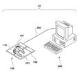
- FIG. 1 is a diagram illustrating an example of an external configuration of a pressure distribution measurement system 10 according to the present embodiment.
- the pressure distribution measurement system 10 includes a pressure distribution meter 100 and an information processing device 200, which are connected by a cable 300.
- the pressure distribution meter 100 includes a first measurement unit 110 and a second measurement unit 120 for measuring the pressure of the part in contact with the subject.
- the first measurement unit 110 includes a first pressure distribution detection sensor 111 in which a plurality of pressure sensors are two-dimensionally arranged, and the second measurement unit 120 is separated from the first pressure distribution detection sensor 111.
- a second pressure distribution detection sensor 121 provided at the position is provided.
- the pressure distribution meter 100 is configured to be foldable between the first and second pressure distribution detection sensors.
- the information processing apparatus 200 acquires the pressure distribution data measured by the pressure distribution meter 100 via the cable 300.
- the acquired pressure distribution data is displayed on the display unit. Thereby, for example, when the pressure distribution meter 100 measures the foot pressure distribution of the subject, the foot pressure distribution of the subject can be displayed, so that the physical therapist can exercise instructions and exercises to the subject. Can be used.
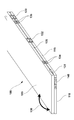
- Appearance structure of pressure distribution meter provided in pressure distribution measurement system> 2A and 2B are views showing a closed state and an open state, respectively, of the external configuration of the pressure distribution meter 100 according to the first embodiment of the present invention.
- the first measurement unit 110 and the second measurement unit 120 included in the pressure distribution meter 100 have substantially the same outer dimensions, and each has a vertically long flat plate shape.
- the first measurement unit 110 and the second measurement unit 120 are rotatably connected on one side of the long side. Specifically, the side surface 115 of the first measurement unit 110 is connected to the side surface 125 of the second measurement unit 120 having substantially the same outer dimensions as the first measurement unit 110 via the hinge mechanism 131-133. Thus, the second measurement unit 120 can be opened and closed (foldable) in the direction of the arrow 130 with respect to the first measurement unit 110.
- the second measurement unit 120 is configured to open up to, for example, 180 degrees with respect to the first measurement unit 110. In the state where the second measurement unit 120 is opened up to the maximum angle, as shown in FIG. And the second measuring unit 120 form the same plane.
- hinge mechanisms 131 to 133 it is assumed that a wiring for electrically connecting the first measurement unit 110 and the second measurement unit 120 is inserted in the hinge mechanism 131. Thereby, transmission / reception of signals between the first measurement unit 110 and the second measurement unit 120 is possible.
- the side surface 115 of the first measurement unit 110 and the side surface 125 of the second measurement unit 120 are configured to face each other in a state of being opened up to the maximum angle (180 degrees).
- rectangular connection portions 134 and 135 are arranged.
- Each of the connecting portions 134 and 135 is configured by a member such as a magnet, and is configured such that the opposing surfaces are attracted to each other when the connecting portions 134 and 135 are opened to the maximum angle.
- the 2nd measurement part 120 can maintain stably the state opened to the maximum angle with respect to the 1st measurement part 110.
- connecting portions 134 and 135 may be configured to be electrically connected to each other in a state where the second measuring unit 120 is opened to the maximum angle with respect to the first measuring unit 110. It may function as a contact for detecting that the state has been opened.
- the power switch 140 is used to turn on / off the power supply of the pressure distribution meter 100.
- a cable 300 for transmitting various data to an external device is connected to a connector (not shown).
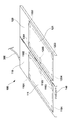
- FIG. 2B shows a state in which the second measuring unit 120 is opened to the maximum angle with respect to the first measuring unit 110.
- the first measurement unit 110 includes a first pressure distribution detection sensor 111, and includes a plurality of pressure sensors 1101-1105.
- the second measurement unit 120 includes a second pressure distribution detection sensor 121, and includes a plurality of pressure sensors 1201-1205.
- the pressure distribution data detected by the first and second pressure distribution detection sensors 111 is transmitted to the information processing device 200 via the cable 300.
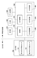
- FIG. 3 is a diagram illustrating a functional configuration of the pressure distribution meter 100 and the information processing apparatus 200 included in the pressure distribution measurement system 10.
- the pressure distribution meter 100 includes a first pressure distribution detection sensor 111 and a second pressure distribution detection sensor 121.
- the information processing apparatus 200 includes a control unit 201, a pressure distribution acquisition unit 202 (pressure distribution acquisition unit), a pressure estimation unit 203 (pressure estimation unit), and a pressure interpolation unit 204 (pressure interpolation unit).
- the information processing apparatus 200 is connected to a display unit 210 (display unit), an input unit 220, and a data storage unit 230.
- the control unit 201 controls the operation of each component by reading and executing a program stored in a storage medium such as the data storage unit 230 or an internal memory (not shown).
- the pressure distribution acquisition unit 202 acquires the pressure distribution data detected by the first pressure distribution detection sensor 111 and the second pressure distribution detection sensor 121 from the pressure distribution meter 100. Based on the pressure distribution data acquired by the pressure distribution acquisition unit 202, the pressure estimation unit 203 is a folded region of the pressure distribution meter (an area between the first pressure distribution detection sensor 111 and the second pressure distribution detection sensor 121).
- the pressure interpolating unit 204 for estimating the pressure of the folding region interpolates the pressure in the folding region with the pressure estimated by the pressure estimating unit 203.
- the display unit 210 is, for example, a liquid crystal display, and displays the pressure distribution data in which the pressure in the folded region is interpolated by the pressure interpolation unit 204.
- the input unit 220 includes, for example, a keyboard, a mouse, a touch panel, or the like, and accepts various inputs from the user.
- the data storage unit 230 stores a program executed by the control unit 201, pressure distribution data acquired from the pressure distribution meter 100, pressure distribution data after interpolation processed by the pressure estimation unit 203 and the pressure interpolation unit 204, and the like.
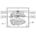
- FIG. 4 is a diagram illustrating an example in which the load on the subject's foot is applied across the first and second pressure distribution detection sensors 111 and 121 in the pressure distribution meter 100 according to the first embodiment of the present invention. .
- the load on the subject's foot is also applied.
- pressure distribution data cannot be acquired.
- an example in which pressure distribution data in the folding region 400 is estimated and interpolated will be described.
- the pressure distribution acquisition unit 202 acquires the pressure distribution data detected by the first and second pressure distribution detection sensors 111 and 121 of the pressure distribution meter 100.
- the pressure estimation unit 203 estimates the pressure distribution data of the folding region of the pressure distribution meter using the acquired pressure distribution data.
- each of the first pressure distribution detection sensor 111 and the second pressure distribution detection sensor 121 of the pressure distribution meter 100 includes a plurality of pressure sensors.
- the first pressure distribution detection sensor 111 is defined as Cell1
- the second pressure distribution detection sensor 121 is defined as Cell2.
- the sensor value of each pressure sensor arranged on the end of Cell1 facing Cell2 is defined as Cell1 (1), ..., Cell1 (j), ..., and on the end of Cell2 facing Cell1 Are defined as Cell2 (1),..., Cell2 (j),.
- the pressure estimation unit 203 estimates the sensor interpolation value as pressure distribution data of the folded region.
- the pressure interpolation unit 204 uses the pressure distribution estimated by the pressure estimation unit 203 to interpolate the pressure distribution data in the folded region.
- each process in the flowchart of FIG. 5 is completed.
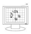
- the pressure distribution data interpolated by the processing of FIG. 5 is transferred to the display unit 210 and displayed.
- the display example is as shown in FIG. According to the present embodiment, even when the pressure distribution detected by the folding pressure distribution meter is displayed, as shown in the display unit 210 of FIG. 7, the sensor values of the folding region are continuously interpolated. Pressure display is possible.
- the width of the folding region (the distance between the first pressure distribution detection sensor 111 and the second pressure distribution detection sensor 121) is equal to one pressure sensor.
- the case has been described as an example.
- sensor values are interpolated by taking as an example a case where the width of the folding region is equal to or more than two pressure sensors.
- the operation of the pressure estimation unit 203 in S502 of the first embodiment is different from that of the first embodiment.
- the width of the folding region is two pressure sensors (two rows).
- the first pressure distribution detection sensor 111 is defined as Cell1
- the second pressure distribution detection sensor 121 is defined as Cell2.
- the sensor value of each pressure sensor arranged on the end of Cell1 facing Cell2 is defined as Cell1 (1), ..., Cell1 (j), ..., and on the end of Cell2 facing Cell1 Are defined as Cell2 (1),..., Cell2 (j),.
- the pressure estimation unit 203 estimates the sensor interpolation value as pressure distribution data of the folded region. Other processes are the same as those in the first embodiment.
- processing is performed as in the first embodiment. If the number is equal to two, control may be performed so as to perform processing as in the second embodiment.
- weighted linear interpolation is performed, so that the influence of the sensor value present at a position close to the sensor value of the pressure sensor of interest is influenced by the sensor value present at a far position. Therefore, the sensor value can be interpolated closer to the actual pressure distribution.
- the width of the folding region is two pressure sensors
- weight interpolation may be performed in the same manner when the width is three or more.
- the width of the folding region is n pressure sensors (for n rows)
- the first pressure distribution detection sensor 111 is defined as Cell1
- the second pressure distribution detection is performed as in the first embodiment.
- the sensor 121 is defined as Cell2.
- the sensor value of each pressure sensor arranged on the end of Cell1 facing Cell2 is defined as Cell1 (1), ..., Cell1 (j), ..., and on the end of Cell2 facing Cell1 Are defined as Cell2 (1),..., Cell2 (j),.
- the sensor value of the pressure sensor of the first pressure distribution detection sensor 111 and the sensor value of the pressure sensor of the second pressure distribution detection sensor 121 arranged at the position closest to the pressure sensor. was used to interpolate the sensor values in the folded region.
- the third embodiment as shown in FIG. 10, when the load on the subject's foot is applied in an oblique direction across the first and second pressure distribution detection sensors 111 and 121, the sensor value is measured. An example of interpolation is described.
- FIG. 9 is a diagram illustrating a functional configuration of the pressure distribution meter 100 and the information processing apparatus 200 included in the pressure distribution measurement system 10 according to the third embodiment.
- the configuration is the same as that described in the first embodiment, except that the information processing apparatus 200 according to the present embodiment further includes a direction determination unit 901 (direction determination unit).
- the direction determination unit 901 determines the traveling direction of the subject (foot direction) based on the foot pressure distribution acquired by the pressure distribution acquisition unit 202. ).
- the traveling direction for example, foot pressure distribution data in a plurality of directions is stored in advance, and the closest direction by template matching with the acquired foot pressure distribution is determined as the traveling direction of the subject.
- the acquired foot pressure distribution may be determined by direct image analysis.
- any method may be used as long as the traveling direction (foot direction) of the subject can be determined.
- the first pressure distribution detection sensor 111 is defined as Cell1
- the second pressure distribution detection sensor 121 is defined as Cell2.
- the sensor value of each pressure sensor arranged on the end of Cell1 facing Cell2 is defined as Cell1 (1), ..., Cell1 (j), ..., and on the end of Cell2 facing Cell1 Are defined as Cell2 (1),..., Cell2 (m),.
- the pressure estimation unit 203 uses the first sensor value detected by the pressure sensor adjacent to the folding region among the plurality of pressure sensors included in the first pressure distribution detection sensor 111 (Cell1 ( j)) and a pressure sensor that is adjacent to the folding region among the plurality of pressure sensors of the second pressure distribution detection sensor 121 and is on a straight line parallel to the traveling direction determined by the direction determination unit 901.
- the pressure Cell (k) in the folding region is estimated by performing linear interpolation based on the detected second sensor value (Cell2 (m)).
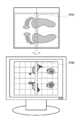
- the pressure estimation unit 203 estimates the sensor interpolation value as pressure distribution data of the folded region. Thereby, as shown in the display part 210 of FIG. 12, the pressure display appropriately interpolated in the oblique direction becomes possible.
- the direction determination unit 901 determines the foot direction, thereby performing sensor value interpolation in accordance with the foot direction. Therefore, even when displaying the pressure distribution detected by the folding pressure distribution meter, the continuous pressure in which the sensor value of the folding area is interpolated without depending on the direction of the pressure distribution of the subject. Display becomes possible, and interpolation according to the actual foot pressure distribution becomes possible.
- the method of this embodiment may be applied in combination with the method described in the second embodiment.
- the sensor value of the pressure sensor of the first pressure distribution detection sensor 111 and the sensor value of the pressure sensor of the second pressure distribution detection sensor 121 arranged at the position closest to the pressure sensor. was used to interpolate the sensor values in the folded region.
- the fourth embodiment as shown in FIG. 14, when the load on the subject's foot is applied over the region between the pressure distribution meter 100 and the second pressure distribution meter 1300. An example of interpolating sensor values will be described.
- Physiotherapists have a need to confirm the walking state of the subject by visually recognizing the pressure distribution when the subject walks on these using a plurality of pressure distribution meters.
- the sensor value is acquired in the same manner as the folding region described in the first to third embodiments. I can't.
- a configuration for enabling continuous pressure display by interpolating the sensor values in the area between the pressure distribution meters and effectively using it for confirmation of a walking state, diagnosis, and the like will be described.
- FIG. 13 is a diagram illustrating a functional configuration of the pressure distribution meter 100, the second pressure distribution meter 1300, and the information processing apparatus 200 included in the pressure distribution measurement system 10 according to the fourth embodiment.
- a second pressure distribution meter 1300 is further provided, and the information processing device 200 is connected to these two pressure distribution meters. Is different.
- the second pressure distribution meter 1300 includes a third pressure distribution detection sensor 1311 and a fourth pressure distribution detection sensor 1321.
- the configuration of the second pressure distribution meter 1300 is the same as that of the pressure distribution meter 100.
- the region between the second pressure distribution detection sensor 121 included in the pressure distribution meter 100 and the third pressure distribution detection sensor 1311 included in the second pressure distribution meter 1300 is illustrated.
- the sensor value shall be interpolated.
- the pressure distribution acquisition unit 202 acquires the pressure distribution data detected by the first and second pressure distribution detection sensors 111 and 121 of the pressure distribution meter 100.
- the pressure distribution acquisition unit 202 acquires the pressure distribution data detected by the third and fourth pressure distribution detection sensors 1311 and 1321 of the second pressure distribution meter 1300. Note that the order of the processes of S1501 and S1502 may be reversed.
- step S1503 the pressure estimation unit 203 uses the acquired pressure distribution data to determine a region between the pressure distribution meter 100 and the second pressure distribution meter 1300 (between the second and third pressure distribution detection sensors 121 and 1311). Area) pressure distribution data.
- the width of the region between the pressure distribution meters (the width between the second and third pressure distribution detection sensors 121 and 1311) is assumed to be one pressure sensor.
- the estimation of the sensor value in the area between the second and third pressure distribution detection sensors 121 and 1311 may be specified by the input unit 220, for example. Similar to the first embodiment, the estimation may be performed using the sensor values at the ends of the second and third pressure distribution detection sensors 121 and 1311.
- step S1504 the pressure interpolation unit 204 uses the estimated pressure distribution to determine a region between the pressure distribution meter 100 and the second pressure distribution meter 1300 (between the second and third pressure distribution detection sensors 121 and 1311). The pressure distribution data in the area (1) is interpolated.
- the pressure distribution data interpolated by the processing of FIG. 15 is transferred to the display unit 210 and displayed.
- the display example is as shown in FIG. According to the present embodiment, even when the pressure distribution detected by a plurality of folding pressure distribution meters is displayed, the sensor value between the pressure distribution meters is displayed as shown in the display unit 210 of FIG. Interpolated continuous pressure display is possible.
- the foot pressure distribution has been mainly described.
- the present invention is not limited to the interpolation of the foot pressure distribution, and is intended for the seat pressure distribution, the body pressure distribution, and the like. Also good.
- the hinge mechanism 133 is included as a fold, but the present invention is not limited to this. Anything can be used as long as it is folded, and for example, a shape such as a cloth can be folded at the crease. Moreover, it is not limited to folding, For example, the shape which can isolate
Landscapes
- Health & Medical Sciences (AREA)
- Life Sciences & Earth Sciences (AREA)
- Physics & Mathematics (AREA)
- Molecular Biology (AREA)
- Animal Behavior & Ethology (AREA)
- Pathology (AREA)
- Engineering & Computer Science (AREA)
- Biomedical Technology (AREA)
- Heart & Thoracic Surgery (AREA)
- Medical Informatics (AREA)
- Veterinary Medicine (AREA)
- Surgery (AREA)
- Biophysics (AREA)
- General Health & Medical Sciences (AREA)
- Public Health (AREA)
- General Physics & Mathematics (AREA)
- Dentistry (AREA)
- Oral & Maxillofacial Surgery (AREA)
- Physiology (AREA)
- Measurement Of The Respiration, Hearing Ability, Form, And Blood Characteristics Of Living Organisms (AREA)
Description
本発明は、情報処理装置、情報処理装置の制御方法、圧分布計測システム、および記憶媒体に関する。
高齢化に伴い脳卒中などの脳神経系疾患を発症する患者や、関節症など運動器に関連する疾患が増加している。発症すると運動機能が低下するため、理学療法士の指導/監視のもと運動機能回復訓練が行われる。
従来より、患者の運動器の状態を観察するものとして、足部の状態を計測する圧分布センサシート等の圧分布計が提案されており(例えば、特許文献1参照)、被検者の扁平足の程度や、重心位置の揺れ等を計測することができる。
足圧分布計に対する患者の圧力のかかり方を見ることにより、患者が何れの部分で体を支えているかを判定でき、理学療法士によるその先の運動指示や訓練に使用することができる。
本願出願人は、このようなセンサシートを折り畳み式にすることで、より持ち運びが容易になり、場所を問わず計測を行うことが可能になると考えた。しかしながら、折り畳式のセンサシートの場合、図17の領域1701に示すように折り畳み部にはセンサを配置することができないため、折り畳み部に圧力が加わる場合にはその圧力を検出することができない。そのため、図17の領域1702に示すように折り畳み部について圧表示が得られないという課題がある。
上記の課題に鑑み、本発明は、折り畳み式の圧分布計により検出された圧分布であっても、連続的な圧表示を可能にする情報処理装置を提供することを目的とする。
上記の目的を達成する本発明に係る情報処理装置は、
複数の圧力センサが2次元に配列された第1の圧分布検出センサと、前記第1の圧分布検出センサと離間した位置に設けられた第2の圧分布検出センサとを含み、前記第1及び第2の圧分布検出センサ間で折り畳み可能な圧分布計と接続可能な情報処理装置であって、
前記圧分布計から前記第1及び第2の圧分布検出センサにより検出された圧分布を取得する圧分布取得手段と、
前記圧分布取得手段により取得された前記圧分布に基づいて、前記圧分布計の折り畳み領域の圧力を推定する圧力推定手段と、
前記圧力推定手段により推定された圧力で前記折り畳み領域の圧力を補間する圧力補間手段と、
を備えることを特徴とする。
複数の圧力センサが2次元に配列された第1の圧分布検出センサと、前記第1の圧分布検出センサと離間した位置に設けられた第2の圧分布検出センサとを含み、前記第1及び第2の圧分布検出センサ間で折り畳み可能な圧分布計と接続可能な情報処理装置であって、
前記圧分布計から前記第1及び第2の圧分布検出センサにより検出された圧分布を取得する圧分布取得手段と、
前記圧分布取得手段により取得された前記圧分布に基づいて、前記圧分布計の折り畳み領域の圧力を推定する圧力推定手段と、
前記圧力推定手段により推定された圧力で前記折り畳み領域の圧力を補間する圧力補間手段と、
を備えることを特徴とする。
本発明によれば、折り畳み式の圧分布計により検出された圧分布であっても、連続的な圧表示が可能になる。
本発明のその他の特徴及び利点は、添付図面を参照とした以下の説明により明らかになるであろう。なお、添付図面においては、同じ若しくは同様の構成には、同じ参照番号を付している。
添付図面は明細書に含まれ、その一部を構成し、本発明の実施の形態を示し、その記述と共に本発明の原理を説明するために用いられる。
本発明の第1実施形態に係る圧分布計測システム10の外観構成の一例を示す図である。
本発明の第1実施形態に係る圧分布計100の外観構成(閉状態)の一例を示す図である。
本発明の第1実施形態に係る圧分布計100の外観構成(開状態)の一例を示す図である。
本発明の第1実施形態に係る圧分布計測システム10が備える圧分布計100および情報処理装置200の機能構成を示す図である。
本発明の第1実施形態に係る圧分布計100において、被検者の足の荷重が第1及び第2の圧分布検出センサ111,121に渡って加わる例を示す図である。
本発明の第1実施形態に係る情報処理装置200が実施する処理の手順を示すフローチャートである。
本発明の第1実施形態に係る情報処理装置200の圧力推定部202が実施する処理の説明図である。
本発明の第1実施形態に係る情報処理装置200の圧力補間部203が圧力補間を行った後の圧分布表示の一例である。
本発明の第2実施形態に係る情報処理装置200の圧力推定部202が実施する処理の説明図である。
本発明の第3実施形態に係る圧分布計測システム10が備える圧分布計100および情報処理装置200の機能構成を示す図である。
本発明の第3実施形態に係る圧分布計100において、被検者の足の荷重が第1及び第2の圧分布検出センサ111,121に渡って斜め方向に加わる例を示す図である。
本発明の第3実施形態に係る情報処理装置200の圧力推定部202が実施する処理の説明図である。
本発明の第3実施形態に係る情報処理装置200の圧力補間部203が圧力補間を行った後の圧分布表示の一例である。
本発明の第4実施形態に係る圧分布計測システム10が備える圧分布計100、第2の圧分布計1300および情報処理装置200の機能構成を示す図である。
本発明の第4実施形態に係る圧分布計100および第2の圧分布計1300において、被検者の足の荷重が第2の圧分布検出センサ121および第3の圧分布検出センサ1311に渡って加わる例を示す図である。
本発明の第4実施形態に係る情報処理装置200が実施する処理の手順を示すフローチャートである。
本発明の第4実施形態に係る情報処理装置200の圧力補間部203が圧力補間を行った後の圧分布表示の一例である。
折り畳み式の圧分布計の一例を示す図である。
以下、本発明の実施形態について図面を参照しながら説明する。なお、以下に述べる実施形態は、本発明の好適な具体例であるから、技術的に好ましい種々の限定が付されているが、本発明の範囲は、以下の説明において特に本発明を限定する旨の記載がない限り、これらの態様に限られるものではない。
[第1実施形態]
<1.圧分布計測システムの外観構成>
図1は、本実施形態に係る圧分布計測システム10の外観構成の一例を示す図である。圧分布計測システム10は、圧分布計100と、情報処理装置200とを備えており、これらはケーブル300によって接続されている。
<1.圧分布計測システムの外観構成>
図1は、本実施形態に係る圧分布計測システム10の外観構成の一例を示す図である。圧分布計測システム10は、圧分布計100と、情報処理装置200とを備えており、これらはケーブル300によって接続されている。
圧分布計100は、被検者と接触した部位の圧力を測定するための第1の測定部110と第2の測定部120とを備えている。第1の測定部110は、複数の圧力センサが2次元に配列された第1の圧分布検出センサ111を備え、第2の測定部120は、当該第1の圧分布検出センサ111と離間した位置に設けられた第2の圧分布検出センサ121を備えている。圧分布計100は、これら第1及び第2の圧分布検出センサ間で折り畳み可能に構成されている。
情報処理装置200は、圧分布計100において計測された圧分布データをケーブル300を介して取得する。また、取得した圧分布データを表示部に表示する。これにより、例えば圧分布計100が被検者の足圧分布を計測する場合、被検者の足圧分布を表示することができるので、理学療法士による被検者への運動指示や訓練に使用することができる。
<2.圧分布計測システムが備える圧分布計の外観構成>
図2Aおよび図2Bはそれぞれ、本発明の第1実施形態に係る圧分布計100の外観構成の閉状態および開状態を示す図である。
図2Aおよび図2Bはそれぞれ、本発明の第1実施形態に係る圧分布計100の外観構成の閉状態および開状態を示す図である。
図2Aに示すように、圧分布計100が備える第1の測定部110および第2の測定部120は、互いに略同一の外形寸法を有しており、それぞれ縦長の平板形状を有する。
第1の測定部110と第2の測定部120とは、それぞれ長辺側の一方の側面において、回動可能に接続されている。具体的には、第1の測定部110の側面115と、第1の測定部110と略等しい外形寸法を有する第2の測定部120の側面125とが、ヒンジ機構131-133を介して接続されており、これにより、第2の測定部120は、第1の測定部110に対して矢印130の方向に開閉可能(折り畳み可能)となっている。
第2の測定部120は第1の測定部110に対して例えば最大180度まで開くよう構成されており、最大角度まで開いた状態において、後述する図2Bに示すように第1の測定部110と第2の測定部120とは、同一平面を形成する。
なお、ヒンジ機構131~133のうち、ヒンジ機構131には、第1の測定部110と第2の測定部120とを電気的に接続するための配線が内挿されているものとする。これにより、第1の測定部110と第2の測定部120との間での信号の送受信が可能となっている。
また、第1の測定部110の側面115と第2の測定部120の側面125には、それぞれ、最大角度(180度)まで開いた状態において互いが対向して配されるように構成された、矩形状の接続部134及び135が配されている。接続部134及び135は、それぞれマグネット等の部材により構成されており、最大角度まで開いた状態において対向する面と面とが吸着するように構成されている。これにより、第2の測定部120は、第1の測定部110に対して最大角度まで開いた状態を安定して維持することができる。
さらに、接続部134及び135は、第2の測定部120が第1の測定部110に対して最大角度まで開いた状態においてそれぞれ電気的にも接続されるように構成されてもよく、最大角度まで開いた状態となったことを検知する接点として機能してもよい。
また電源スイッチ140は、圧分布計100の電源をON/OFFするために用いられる。不図示のコネクタには、各種データを外部装置(不図示のパソコン等の情報処理装置や携帯電話等)に送信するためのケーブル300が接続される。
次に図2Bは、第2の測定部120が第1の測定部110に対して最大角度まで開いた状態を示している。
図2Bにおいて、第1の測定部110は、第1の圧分布検出センサ111を備えており、複数の圧力センサ1101-1105を備えている。同様に、第2の測定部120は、第2の圧分布検出センサ121を備えており、複数の圧力センサ1201-1205を備えている。第1及び第2の圧分布検出センサ111により検出された圧分布データがケーブル300を介して情報処理装置200へ送信される。
<3.圧分布計測システムが備える圧分布計および情報処理装置の機能構成>
図3は、圧分布計測システム10が備える圧分布計100および情報処理装置200の機能構成を示す図である。図3に示すように、圧分布計100は、第1の圧分布検出センサ111と、第2の圧分布検出センサ121とを備える。
図3は、圧分布計測システム10が備える圧分布計100および情報処理装置200の機能構成を示す図である。図3に示すように、圧分布計100は、第1の圧分布検出センサ111と、第2の圧分布検出センサ121とを備える。
情報処理装置200は、制御部201と、圧分布取得部202(圧分布取得手段)と、圧力推定部203(圧力推定手段)と、圧力補間部204(圧力補間手段)とを備えている。また情報処理装置200は、表示部210(表示手段)と、入力部220と、データ記憶部230と接続されている。
制御部201は、データ記憶部230または不図示の内部メモリ等の記憶媒体に記憶されたプログラムを読み出して実行することにより、各構成要素の動作を制御する。
圧分布取得部202は、第1の圧分布検出センサ111および第2の圧分布検出センサ121により検出された圧分布データを、圧分布計100から取得する。圧力推定部203は、圧分布取得部202により取得された圧分布データに基づいて、圧分布計の折り畳み領域(第1の圧分布検出センサ111および第2の圧分布検出センサ121の間の領域)の圧力を推定する圧力補間部204は、圧力推定部203により推定された圧力で、折り畳み領域の圧力を補間する。
表示部210は、例えば液晶ディスプレイであり、圧力補間部204により折り畳み領域の圧力が補間された圧分布データを表示する。入力部220は、例えばキーボード、マウス、またはタッチパネル等で構成されており、ユーザからの各種入力を受け付ける。データ記憶部230は、制御部201が実行するプログラムを格納したり、圧分布計100から取得した圧分布データや、圧力推定部203および圧力補間部204により処理された補間後の圧分布データ等を記憶する。
<4.情報処理装置200が実施する処理の手順>
図4は、本発明の第1実施形態に係る圧分布計100において、被検者の足の荷重が第1及び第2の圧分布検出センサ111,121に渡って加わる例を示す図である。図4の折り畳み領域400においても被検者の足の荷重が加わっているが、当該折り畳み領域400には圧力センサが配置されていないため、圧分布データを取得することができない。本実施形態では、この折り畳み領域400の圧分布データを推定して補間する例を説明する。
図4は、本発明の第1実施形態に係る圧分布計100において、被検者の足の荷重が第1及び第2の圧分布検出センサ111,121に渡って加わる例を示す図である。図4の折り畳み領域400においても被検者の足の荷重が加わっているが、当該折り畳み領域400には圧力センサが配置されていないため、圧分布データを取得することができない。本実施形態では、この折り畳み領域400の圧分布データを推定して補間する例を説明する。
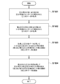
以下、図5のフローチャートを参照して、第1実施形態に係る情報処理装置200が実施する処理の手順を説明する。
S501において、圧分布取得部202は、圧分布計100の第1及び第2の圧分布検出センサ111,121により検出された圧分布データを取得する。
S502において、圧力推定部203は、取得した圧分布データを用いて圧分布計の折り畳み領域の圧力分布データを推定する。
ここで図6を参照して、圧力推定部203の圧力分布データの推定処理について説明する。図6に示すように、折り畳み領域の幅は圧力センサ1つ分(1列分)である。図2Bを参照して説明したように、圧分布計100の第1の圧分布検出センサ111および第2の圧分布検出センサ121は、それぞれ複数の圧力センサを有している。第1の圧分布検出センサ111をCell1と定義し、第2の圧分布検出センサ121をCell2と定義する。また、Cell2と対向するCell1の端部上に配置されている各圧力センサのセンサ値をCell1(1)、…、Cell1(j)、…、と定義し、Cell1と対向するCell2の端部上に配置されている各圧力センサのセンサ値をCell2(1)、…、Cell2(j)、…、と定義する。このとき、折り畳み領域のセンサ補間値Cell(1)、…、Cell(j)、…、はそれぞれ、Cell(1)={Cell1(1)+Cell2(1)}/2、…、Cell(1)={Cell1(j)+Cell2(j)}/2、…、として線形補間により導出される。圧力推定部203は、当該センサ補間値を折り畳み領域の圧力分布データとして推定する。
S503において、圧力補間部204は、圧力推定部203により推定された圧力分布を使用して折り畳み領域の圧分布データを補間する。
以上で図5のフローチャートの各処理が終了する。なお図5の処理で補間された圧分布データは表示部210へ転送されて表示される。その表示例が図7のようになる。本実施形態によれば、折り畳み式の圧分布計により検出された圧分布を表示する場合であっても、図7の表示部210に示されるように、折り畳み領域のセンサ値が補間された連続的な圧表示が可能となる。
[第2実施形態]
第1実施形態では、図6を参照して説明したように、折り畳み領域の幅(第1の圧分布検出センサ111および第2の圧分布検出センサ121の間の距離)が圧力センサ1つ分である場合を例に説明した。これに対し、第2実施形態では、折り畳み領域の幅が圧力センサ2つ分以上である場合を例としてセンサ値の補間を行う。
第1実施形態では、図6を参照して説明したように、折り畳み領域の幅(第1の圧分布検出センサ111および第2の圧分布検出センサ121の間の距離)が圧力センサ1つ分である場合を例に説明した。これに対し、第2実施形態では、折り畳み領域の幅が圧力センサ2つ分以上である場合を例としてセンサ値の補間を行う。
圧分布計100および情報処理装置200の構成は第1実施形態と同様であるため説明を省略する。
本実施形態では、第1実施形態のS502における圧力推定部203の動作が第1実施形態とは異なる。
ここで図8を参照して、本実施形態に係る圧力推定部203の圧力分布データの推定処理について説明する。図8に示すように、折り畳み領域の幅は圧力センサ2つ分(2列分)である。第1実施形態と同様に、第1の圧分布検出センサ111をCell1と定義し、第2の圧分布検出センサ121をCell2と定義する。また、Cell2と対向するCell1の端部上に配置されている各圧力センサのセンサ値をCell1(1)、…、Cell1(j)、…、と定義し、Cell1と対向するCell2の端部上に配置されている各圧力センサのセンサ値をCell2(1)、…、Cell2(j)、…、と定義する。このとき、Cell1側の折り畳み領域のセンサ補間値Cell(1,1)、…、Cell(1,j)、…、はそれぞれ、Cell(1,1)={2Cell1(1)+Cell2(1)}/3、…、Cell(1,j)={2Cell1(j)+Cell2(j)}/3、…、として重み付け線形補間(加重平均)により導出される。同様に、Cell2側の折り畳み領域のセンサ補間値Cell(2,1)、…、Cell(2,j)、…、はそれぞれ、Cell(2,1)={Cell1(1)+2Cell2(1)}/3、…、Cell(2,j)={Cell1(j)+2Cell2(j)}/3、…、として重み付け線形補間(加重平均)により導出される。圧力推定部203は、当該センサ補間値を折り畳み領域の圧力分布データとして推定する。その他の処理については第1実施形態と同様である。
ここで折り畳み領域の幅が圧力センサ何個分に相当するかという情報を、圧分布計100から情報処理装置200が取得することで、1つ分である場合は第1実施形態のように処理を行い、2つ分である場合には第2実施形態のように処理を行うように制御すればよい。
以上説明したように、本実施形態では、重み付け線形補間(加重平均)を行うため、着目する圧力センサのセンサ値に近い位置に存在するセンサ値の影響が、遠い位置に存在するセンサ値の影響よりも強くなるため、より現実の圧分布に近いセンサ値の補間を行うことが可能となる。
本実施形態によれば、折り畳み式の圧分布計により検出された圧分布を表示する場合であっても、折り畳み領域のセンサ値が補間された連続的な圧表示が可能となる。
なお、本実施形態では、折り畳み領域の幅が圧力センサ2つ分である場合を例に説明を行ったが、3つ分以上である場合も同様にして、重み付け補間を実施すればよい。例えば、折りたたみ領域の幅は圧力センサn個分(n列分)である場合に、第1実施形態と同様に、第1の圧分布検出センサ111をCell1と定義し、第2の圧分布検出センサ121をCell2と定義する。また、Cell2と対向するCell1の端部上に配置されている各圧力センサのセンサ値をCell1(1)、…、Cell1(j)、…、と定義し、Cell1と対向するCell2の端部上に配置されている各圧力センサのセンサ値をCell2(1)、…、Cell2(j)、…、と定義する。このとき、Cell1側からi列目(iは1ないしnの整数)の折り畳み領域のセンサ補間値Cell(i,j)は、Cell(i,j)={(n+1-i)×Cell1(j)+i×Cell2(j)}/(n+1)、…、として重み付け線形補間(加重平均)により導出される。
[第3実施形態]
第1実施形態では、第1の圧分布検出センサ111の圧力センサのセンサ値と、当該圧力センサと最も隣接する位置に配置されている第2の圧分布検出センサ121の圧力センサのセンサ値とを用いて、間の折り畳み領域のセンサ値を補間した。これに対して、第3実施形態では、図10に示すように、被検者の足の荷重が第1及び第2の圧分布検出センサ111,121に渡って斜め方向に加わる場合にセンサ値を補間する例を説明する。
第1実施形態では、第1の圧分布検出センサ111の圧力センサのセンサ値と、当該圧力センサと最も隣接する位置に配置されている第2の圧分布検出センサ121の圧力センサのセンサ値とを用いて、間の折り畳み領域のセンサ値を補間した。これに対して、第3実施形態では、図10に示すように、被検者の足の荷重が第1及び第2の圧分布検出センサ111,121に渡って斜め方向に加わる場合にセンサ値を補間する例を説明する。
図9は、第3実施形態に係る圧分布計測システム10が備える圧分布計100および情報処理装置200の機能構成を示す図である。第1実施形態で説明した構成と同様であるが、本実施形態に係る情報処理装置200が方向判定部901(方向判定手段)をさらに備えている点が異なっている。
方向判定部901は、圧分布計100により被検者の足圧分布が検出された場合、圧分布取得部202により取得された足圧分布に基づいて、被検者の進行方向(足の向き)を判定する。進行方向を判定する方法としては、例えば複数の向きでの足圧分布データを予め保持しておき、取得した足圧分布とのテンプレートマッチングにより最も近い向きを、被検者の進行方向と判定する方法が考えられる。あるいは、取得した足圧分布を直接画像解析して判定してもよい。その他、被検者の進行方向(足の向き)が判定できれば何れの手法を用いてもよい。
ここで図11を参照して、第3実施形態に係る情報処理装置200の圧力推定部203が実施する処理を説明する。
第1実施形態と同様に、第1の圧分布検出センサ111をCell1と定義し、第2の圧分布検出センサ121をCell2と定義する。また、Cell2と対向するCell1の端部上に配置されている各圧力センサのセンサ値をCell1(1)、…、Cell1(j)、…、と定義し、Cell1と対向するCell2の端部上に配置されている各圧力センサのセンサ値をCell2(1)、…、Cell2(m)、…、と定義する。
方向判定部901により、矢印1110の方向が進行方向(足の向き)であると判定されたとする。その場合、圧力推定部203は、第1の圧分布検出センサ111が有する複数の圧力センサのうち折り畳み領域に隣接する圧力センサにより検出された第1のセンサ値(図11の例では、Cell1(j))と、第2の圧分布検出センサ121が有する複数の圧力センサのうち折り畳み領域に隣接する圧力センサであって方向判定部901により判定された進行方向と平行な直線上の圧力センサにより検出された第2のセンサ値(Cell2(m))とに基づいて線形補間を行うことにより折り畳み領域の圧力Cell(k)を推定する。より具体的には、折り畳み領域のセンサ補間値は、Cell(k)={Cell1(j)+Cell2(m)}/2として線形補間により導出される。圧力推定部203は、当該センサ補間値を折り畳み領域の圧力分布データとして推定する。これにより、図12の表示部210に示すように、斜め方向に適切に補間された圧表示が可能となる。
以上説明したように、本実施形態では、方向判定部901により足の向きを判定することで、足の向きに合わせたセンサ値補間を行う。これにより、折り畳み式の圧分布計により検出された圧分布を表示する場合であっても、被検者の圧分布の方向に依存することなく折り畳み領域のセンサ値が補間された連続的な圧表示が可能となりより、実際の足圧分布に即した補間が可能になる。
なお、折り畳み領域の幅が圧力センサ2つ分以上である場合には第2実施形態で説明した方法と併せて本実施形態の方法を適用してもよい。
[第4実施形態]
第1実施形態では、第1の圧分布検出センサ111の圧力センサのセンサ値と、当該圧力センサと最も隣接する位置に配置されている第2の圧分布検出センサ121の圧力センサのセンサ値とを用いて、間の折り畳み領域のセンサ値を補間した。これに対して、第4実施形態では、図14に示すように、被検者の足の荷重が圧分布計100と、第2の圧分布計1300との間の領域に渡って加わる場合にセンサ値を補間する例を説明する。
第1実施形態では、第1の圧分布検出センサ111の圧力センサのセンサ値と、当該圧力センサと最も隣接する位置に配置されている第2の圧分布検出センサ121の圧力センサのセンサ値とを用いて、間の折り畳み領域のセンサ値を補間した。これに対して、第4実施形態では、図14に示すように、被検者の足の荷重が圧分布計100と、第2の圧分布計1300との間の領域に渡って加わる場合にセンサ値を補間する例を説明する。
理学療法士等は、複数の圧分布計を用いて被検者がこれらの上を歩行する際の圧分布を視認することで、被検者の歩行状態を確認したいというニーズがある。図14に示すように2つの圧分布計100,1300の間の領域には圧力センサが配置されていないため、第1乃至第3実施形態で説明した折り畳み領域と同様に、センサ値を取得することができない。本実施形態では、この圧分布計間の領域のセンサ値を補間することで連続的な圧表示を可能とし、歩行状態の確認、診断等に有効利用できるようにするための構成を説明する。
図13は、第4実施形態に係る圧分布計測システム10が備える圧分布計100、第2の圧分布計1300および情報処理装置200の機能構成を示す図である。第1実施形態で説明した圧分布計100、情報処理装置200に加えて、第2の圧分布計1300をさらに備えており、情報処理装置200がこれら2つの圧分布計と接続されている点が異なっている。
第2の圧分布計1300は、第3の圧分布検出センサ1311と、第4の圧分布検出センサ1321とを備えている。第2の圧分布計1300の構成は、圧分布計100と同様である。本実施形態では、図14に示すように圧分布計100が有する第2の圧分布検出センサ121と、第2の圧分布計1300が有する第3の圧分布検出センサ1311との間の領域のセンサ値を補間するものとする。
以下、図15のフローチャートを参照して、第4実施形態に係る情報処理装置200が実施する処理の手順を説明する。
S1501において、圧分布取得部202は、圧分布計100の第1及び第2の圧分布検出センサ111,121により検出された圧分布データを取得する。
S1502において、圧分布取得部202は、第2の圧分布計1300の第3及び第4の圧分布検出センサ1311,1321により検出された圧分布データを取得する。なお、S1501およびS1502の処理は順序が逆であってもよい。
S1503において、圧力推定部203は、取得した圧分布データを用いて圧分布計100と第2の圧分布計1300との間の領域(第2及び第3の圧分布検出センサ121,1311間の領域)の圧分布データを推定する。
ここでは、第1実施形態で説明したように、圧分布計間の領域の幅(第2及び第3の圧分布検出センサ121,1311間の幅)が圧力センサ1つ分であるものとする。第2及び第3の圧分布検出センサ121,1311間の領域のセンサ値を推定することは例えば入力部220により指定すればよい。第1実施形態と同様にして、第2及び第3の圧分布検出センサ121,1311の端部のセンサ値を用いて推定を行えばよい。
S1504において、圧力補間部204は、推定された圧力分布を使用して圧分布計100と第2の圧分布計1300との間の領域(第2及び第3の圧分布検出センサ121,1311間の領域)の圧分布データを補間する。
以上で図15のフローチャートの各処理が終了する。なお図15の処理で補間された圧分布データは表示部210へ転送されて表示される。その表示例が図16のようになる。本実施形態によれば、複数の折り畳み式の圧分布計により検出された圧分布を表示する場合であっても、図16の表示部210に示されるように、圧分布計間のセンサ値が補間された連続的な圧表示が可能となる。
なお、上述した第1乃至第4実施形態では、主に足圧の分布について説明を行ったが、足圧分布の補間に限定されるものではなく、座圧分布、体圧分布などを対象としてもよい。
上述した実施形態では、折りたたみとしてヒンジ機構133を含む構成となっているが、それに限定されない。折りたためれば何でも良く、例えば布のようなものが折り目を境に折り曲がる形状でも良い。また、折りたたみに限定されず、例えば第1の測定部110と第2の測定部120が分離できる形状でも良い。
本発明は上記実施の形態に制限されるものではなく、本発明の精神及び範囲から離脱することなく、様々な変更及び変形が可能である。従って、本発明の範囲を公にするために、以下の請求項を添付する。
Claims (10)
- 複数の圧力センサが2次元に配列された第1の圧分布検出センサと、前記第1の圧分布検出センサと離間した位置に設けられた第2の圧分布検出センサとを含み、前記第1及び第2の圧分布検出センサ間で折り畳み可能な圧分布計と接続可能な情報処理装置であって、
前記圧分布計から前記第1及び第2の圧分布検出センサにより検出された圧分布を取得する圧分布取得手段と、
前記圧分布取得手段により取得された前記圧分布に基づいて、前記圧分布計の折り畳み領域の圧力を推定する圧力推定手段と、
前記圧力推定手段により推定された圧力で前記折り畳み領域の圧力を補間する圧力補間手段と、
を備えることを特徴とする情報処理装置。 - 前記圧力補間手段により補間された圧分布を表示する表示手段をさらに備えることを特徴とする請求項1に記載の情報処理装置。
- 前記圧力推定手段は、
前記第1の圧分布検出センサが有する複数の圧力センサのうち前記折り畳み領域に隣接する圧力センサにより検出された第1のセンサ値と、
前記第2の圧分布検出センサが有する複数の圧力センサのうち前記折り畳み領域に隣接する圧力センサにより検出された第2のセンサ値とに基づいて、
線形補間を行うことにより前記折り畳み領域の圧力を推定することを特徴とする請求項1または2に記載の情報処理装置。 - 前記圧力推定手段は、
前記第1の圧分布検出センサが有する複数の圧力センサのうち前記折り畳み領域に隣接する圧力センサにより検出された第1のセンサ値と、
前記第2の圧分布検出センサが有する複数の圧力センサのうち前記折り畳み領域に隣接する圧力センサであって前記第1のセンサ値が検出された圧力センサと最近接の圧力センサにより検出された第2のセンサ値とに基づいて、
線形補間を行うことにより前記折り畳み領域の圧力を推定することを特徴とする請求項1乃至3の何れか1項に記載の情報処理装置。 - 前記圧分布計により被検者の足圧分布が検出された場合、前記圧分布取得手段により取得された前記足圧分布に基づいて、前記被検者の進行方向を判定する方向判定手段をさらに備え、
前記圧力推定手段は、
前記第1の圧分布検出センサが有する複数の圧力センサのうち前記折り畳み領域に隣接する圧力センサにより検出された第1のセンサ値と、
前記第2の圧分布検出センサが有する複数の圧力センサのうち前記折り畳み領域に隣接する圧力センサであって前記方向判定手段により判定された前記進行方向と平行な直線上の圧力センサにより検出された第2のセンサ値とに基づいて、
線形補間を行うことにより前記折り畳み領域の圧力を推定することを特徴とする請求項1乃至3の何れか1項に記載の情報処理装置。 - 前記圧力推定手段は、前記第1のセンサ値と、前記第2のセンサ値とに基づいて、重み付け線形補間を行うことにより前記折り畳み領域の圧力を推定することを特徴とする請求項3乃至5の何れか1項に記載の情報処理装置。
- 前記情報処理装置は、複数の圧力センサが2次元に配列された第3の圧分布検出センサと、前記第3の圧分布検出センサと離間した位置に設けられた第4の圧分布検出センサとを含み、前記第3及び第4の圧分布検出センサ間で折り畳み可能な第2の圧分布計とさらに接続可能であり、
前記圧分布取得手段は、前記第3及び第4の圧分布検出センサにより検出された第2の圧分布を前記第2の圧分布計からさらに取得し、
前記圧力推定手段は、
前記圧分布計の前記第2の圧分布検出センサにより検出された圧分布と、前記第2の圧分布計の前記第3の圧分布検出センサにより検出された圧分布とに基づいて、前記第2及び第3の圧分布検出センサ間の領域の圧力をさらに推定することを特徴とする請求項1乃至5の何れか1項に記載の情報処理装置。 - 複数の圧力センサが2次元に配列された第1の圧分布検出センサと、前記第1の圧分布検出センサと離間した位置に設けられた第2の圧分布検出センサとを含み、前記第1及び第2の圧分布検出センサ間で折り畳み可能な圧分布計と接続可能な情報処理装置の制御方法であって、
前記圧分布計から前記第1及び第2の圧分布検出センサにより検出された圧分布を取得する圧分布取得工程と、
前記圧分布取得工程により取得された前記圧分布に基づいて、前記圧分布計の折り畳み領域の圧力を推定する圧力推定工程と、
前記圧力推定工程により推定された圧力で前記折り畳み領域の圧力を補間する圧力補間工程と、
を有することを特徴とする情報処理装置の制御方法。 - 請求項8に記載の情報処理装置の制御方法の各工程をコンピュータに実行させるためのプログラムが格納された記憶媒体。
- 圧分布計と、当該圧分布計と接続可能な情報処理装置とを備える圧分布計測システムであって、
前記圧分布計は、
複数の圧力センサが2次元に配列された第1の圧分布検出センサと、前記第1の圧分布検出センサと離間した位置に設けられた第2の圧分布検出センサとを含み、
前記第1及び第2の圧分布検出センサ間で折り畳み可能であり、
前記情報処理装置は、
前記圧分布計から前記第1及び第2の圧分布検出センサにより検出された圧分布を取得する圧分布取得手段と、
前記圧分布取得手段により取得された前記圧分布に基づいて、前記圧分布計の折り畳み領域の圧力を推定する圧力推定手段と、
前記圧力推定手段により推定された圧力で前記折り畳み領域の圧力を補間する圧力補間手段と、
を備えることを特徴とする圧分布計測システム。
Priority Applications (1)
| Application Number | Priority Date | Filing Date | Title |
|---|---|---|---|
| PCT/JP2012/006020 WO2014045321A1 (ja) | 2012-09-21 | 2012-09-21 | 情報処理装置、情報処理装置の制御方法、圧分布計測システム、および記憶媒体 |
Applications Claiming Priority (1)
| Application Number | Priority Date | Filing Date | Title |
|---|---|---|---|
| PCT/JP2012/006020 WO2014045321A1 (ja) | 2012-09-21 | 2012-09-21 | 情報処理装置、情報処理装置の制御方法、圧分布計測システム、および記憶媒体 |
Publications (1)
| Publication Number | Publication Date |
|---|---|
| WO2014045321A1 true WO2014045321A1 (ja) | 2014-03-27 |
Family
ID=50340683
Family Applications (1)
| Application Number | Title | Priority Date | Filing Date |
|---|---|---|---|
| PCT/JP2012/006020 Ceased WO2014045321A1 (ja) | 2012-09-21 | 2012-09-21 | 情報処理装置、情報処理装置の制御方法、圧分布計測システム、および記憶媒体 |
Country Status (1)
| Country | Link |
|---|---|
| WO (1) | WO2014045321A1 (ja) |
Cited By (5)
| Publication number | Priority date | Publication date | Assignee | Title |
|---|---|---|---|---|
| CN105815880A (zh) * | 2016-03-14 | 2016-08-03 | 联想(北京)有限公司 | 一种信息处理方法及电子设备 |
| JP2016180682A (ja) * | 2015-03-24 | 2016-10-13 | テルモ株式会社 | 外力分布測定システムの校正用器具及びその校正方法 |
| JP2017153720A (ja) * | 2016-03-02 | 2017-09-07 | トヨタ自動車株式会社 | 足裏荷重算出装置 |
| JP2017529897A (ja) * | 2014-08-12 | 2017-10-12 | ゴルフゾン カンパニー リミテッド | 運動姿勢分析装置及び運動姿勢分析情報生成方法 |
| JP2018073330A (ja) * | 2016-11-04 | 2018-05-10 | Nissha株式会社 | 入力装置及び仮想空間表示装置 |
Citations (4)
| Publication number | Priority date | Publication date | Assignee | Title |
|---|---|---|---|---|
| JPH10228540A (ja) * | 1997-02-18 | 1998-08-25 | Nippon Telegr & Teleph Corp <Ntt> | 歩行パターン処理装置 |
| JP2005131036A (ja) * | 2003-10-29 | 2005-05-26 | Denso Corp | センサシート |
| JP2006218202A (ja) * | 2005-02-14 | 2006-08-24 | Brother Ind Ltd | 運動時身体状態測定システム及び運動時身体状態測定装置 |
| JP2006284404A (ja) * | 2005-04-01 | 2006-10-19 | Nitta Ind Corp | 圧力分布センサ及び歩行解析装置 |
-
2012
- 2012-09-21 WO PCT/JP2012/006020 patent/WO2014045321A1/ja not_active Ceased
Patent Citations (4)
| Publication number | Priority date | Publication date | Assignee | Title |
|---|---|---|---|---|
| JPH10228540A (ja) * | 1997-02-18 | 1998-08-25 | Nippon Telegr & Teleph Corp <Ntt> | 歩行パターン処理装置 |
| JP2005131036A (ja) * | 2003-10-29 | 2005-05-26 | Denso Corp | センサシート |
| JP2006218202A (ja) * | 2005-02-14 | 2006-08-24 | Brother Ind Ltd | 運動時身体状態測定システム及び運動時身体状態測定装置 |
| JP2006284404A (ja) * | 2005-04-01 | 2006-10-19 | Nitta Ind Corp | 圧力分布センサ及び歩行解析装置 |
Cited By (5)
| Publication number | Priority date | Publication date | Assignee | Title |
|---|---|---|---|---|
| JP2017529897A (ja) * | 2014-08-12 | 2017-10-12 | ゴルフゾン カンパニー リミテッド | 運動姿勢分析装置及び運動姿勢分析情報生成方法 |
| JP2016180682A (ja) * | 2015-03-24 | 2016-10-13 | テルモ株式会社 | 外力分布測定システムの校正用器具及びその校正方法 |
| JP2017153720A (ja) * | 2016-03-02 | 2017-09-07 | トヨタ自動車株式会社 | 足裏荷重算出装置 |
| CN105815880A (zh) * | 2016-03-14 | 2016-08-03 | 联想(北京)有限公司 | 一种信息处理方法及电子设备 |
| JP2018073330A (ja) * | 2016-11-04 | 2018-05-10 | Nissha株式会社 | 入力装置及び仮想空間表示装置 |
Similar Documents
| Publication | Publication Date | Title |
|---|---|---|
| JP6288706B2 (ja) | 上体運動計測システム及び上体運動計測方法 | |
| JP5720295B2 (ja) | 睡眠評価装置および睡眠評価装置における表示方法 | |
| CN104545954B (zh) | 为导管标测力和温度 | |
| US20100312148A1 (en) | Posture evaluating apparatus | |
| EP2687158B1 (en) | Biometric apparatus and computer-readable storage medium storing body image creating program | |
| US8337427B2 (en) | Method of estimating finger-tapping force | |
| JP5034012B2 (ja) | 運動能力検出装置 | |
| Sarsfield et al. | Clinical assessment of depth sensor based pose estimation algorithms for technology supervised rehabilitation applications | |
| JP2014533140A (ja) | ユーザをモニタする装置及びそのような装置を較正する方法 | |
| JP6730573B2 (ja) | 重症度評価支援システム及びプログラム | |
| JP2015134074A (ja) | 生体測定装置 | |
| JP2019054988A (ja) | 協調運動評価方法及びプログラム | |
| Hernandez et al. | A wireless, real-time respiratory effort and body position monitoring system for sleep | |
| CN111671432B (zh) | 惯性传感器的安装姿势推测方法 | |
| KR101087135B1 (ko) | 모션 콘텐츠 기반의 학습 장치 및 방법 | |
| O'Sullivan et al. | The between-day and inter-rater reliability of a novel wireless system to analyse lumbar spine posture | |
| CN107708561B (zh) | 指标导出设备、可佩戴设备以及移动设备 | |
| JP6151703B2 (ja) | 情報処理装置、情報処理装置の制御方法、圧分布計測システム、および記憶媒体 | |
| Tamei et al. | Kinect-based posturography for in-home rehabilitation of balance disorders | |
| Camerlingo et al. | Measuring gait parameters from a single chest-worn accelerometer in healthy individuals: a validation study | |
| Wielgos et al. | Garment integrated spinal posture detection using wearable magnetic sensors | |
| JP2010115378A (ja) | 姿勢制御機能診断装置 | |
| TWM393666U (en) | Vertebra posture detecting device | |
| Passier et al. | Physiotherapist observation of head and neck alignment | |
| Zhang et al. | Human back movement analysis using bsn |
Legal Events
| Date | Code | Title | Description |
|---|---|---|---|
| 121 | Ep: the epo has been informed by wipo that ep was designated in this application |
Ref document number: 12885135 Country of ref document: EP Kind code of ref document: A1 |
|
| NENP | Non-entry into the national phase |
Ref country code: DE |
|
| 122 | Ep: pct application non-entry in european phase |
Ref document number: 12885135 Country of ref document: EP Kind code of ref document: A1 |
|
| NENP | Non-entry into the national phase |
Ref country code: JP |