WO2014041864A1 - 対象物識別装置 - Google Patents
対象物識別装置 Download PDFInfo
- Publication number
- WO2014041864A1 WO2014041864A1 PCT/JP2013/066972 JP2013066972W WO2014041864A1 WO 2014041864 A1 WO2014041864 A1 WO 2014041864A1 JP 2013066972 W JP2013066972 W JP 2013066972W WO 2014041864 A1 WO2014041864 A1 WO 2014041864A1
- Authority
- WO
- WIPO (PCT)
- Prior art keywords
- image
- identification
- unit
- pixel
- data
- Prior art date
- Legal status (The legal status is an assumption and is not a legal conclusion. Google has not performed a legal analysis and makes no representation as to the accuracy of the status listed.)
- Ceased
Links
Images





Classifications
-
- B—PERFORMING OPERATIONS; TRANSPORTING
- B60—VEHICLES IN GENERAL
- B60R—VEHICLES, VEHICLE FITTINGS, OR VEHICLE PARTS, NOT OTHERWISE PROVIDED FOR
- B60R1/00—Optical viewing arrangements; Real-time viewing arrangements for drivers or passengers using optical image capturing systems, e.g. cameras or video systems specially adapted for use in or on vehicles
- B60R1/20—Real-time viewing arrangements for drivers or passengers using optical image capturing systems, e.g. cameras or video systems specially adapted for use in or on vehicles
- B60R1/22—Real-time viewing arrangements for drivers or passengers using optical image capturing systems, e.g. cameras or video systems specially adapted for use in or on vehicles for viewing an area outside the vehicle, e.g. the exterior of the vehicle
- B60R1/23—Real-time viewing arrangements for drivers or passengers using optical image capturing systems, e.g. cameras or video systems specially adapted for use in or on vehicles for viewing an area outside the vehicle, e.g. the exterior of the vehicle with a predetermined field of view
- B60R1/24—Real-time viewing arrangements for drivers or passengers using optical image capturing systems, e.g. cameras or video systems specially adapted for use in or on vehicles for viewing an area outside the vehicle, e.g. the exterior of the vehicle with a predetermined field of view in front of the vehicle
-
- G—PHYSICS
- G06—COMPUTING OR CALCULATING; COUNTING
- G06V—IMAGE OR VIDEO RECOGNITION OR UNDERSTANDING
- G06V10/00—Arrangements for image or video recognition or understanding
- G06V10/40—Extraction of image or video features
- G06V10/44—Local feature extraction by analysis of parts of the pattern, e.g. by detecting edges, contours, loops, corners, strokes or intersections; Connectivity analysis, e.g. of connected components
- G06V10/443—Local feature extraction by analysis of parts of the pattern, e.g. by detecting edges, contours, loops, corners, strokes or intersections; Connectivity analysis, e.g. of connected components by matching or filtering
- G06V10/446—Local feature extraction by analysis of parts of the pattern, e.g. by detecting edges, contours, loops, corners, strokes or intersections; Connectivity analysis, e.g. of connected components by matching or filtering using Haar-like filters, e.g. using integral image techniques
-
- G—PHYSICS
- G06—COMPUTING OR CALCULATING; COUNTING
- G06V—IMAGE OR VIDEO RECOGNITION OR UNDERSTANDING
- G06V10/00—Arrangements for image or video recognition or understanding
- G06V10/40—Extraction of image or video features
- G06V10/50—Extraction of image or video features by performing operations within image blocks; by using histograms, e.g. histogram of oriented gradients [HoG]; by summing image-intensity values; Projection analysis
-
- G—PHYSICS
- G06—COMPUTING OR CALCULATING; COUNTING
- G06V—IMAGE OR VIDEO RECOGNITION OR UNDERSTANDING
- G06V20/00—Scenes; Scene-specific elements
- G06V20/50—Context or environment of the image
- G06V20/56—Context or environment of the image exterior to a vehicle by using sensors mounted on the vehicle
- G06V20/58—Recognition of moving objects or obstacles, e.g. vehicles or pedestrians; Recognition of traffic objects, e.g. traffic signs, traffic lights or roads
-
- G—PHYSICS
- G06—COMPUTING OR CALCULATING; COUNTING
- G06V—IMAGE OR VIDEO RECOGNITION OR UNDERSTANDING
- G06V40/00—Recognition of biometric, human-related or animal-related patterns in image or video data
- G06V40/10—Human or animal bodies, e.g. vehicle occupants or pedestrians; Body parts, e.g. hands
- G06V40/103—Static body considered as a whole, e.g. static pedestrian or occupant recognition
-
- B—PERFORMING OPERATIONS; TRANSPORTING
- B60—VEHICLES IN GENERAL
- B60R—VEHICLES, VEHICLE FITTINGS, OR VEHICLE PARTS, NOT OTHERWISE PROVIDED FOR
- B60R2300/00—Details of viewing arrangements using cameras and displays, specially adapted for use in a vehicle
- B60R2300/30—Details of viewing arrangements using cameras and displays, specially adapted for use in a vehicle characterised by the type of image processing
- B60R2300/307—Details of viewing arrangements using cameras and displays, specially adapted for use in a vehicle characterised by the type of image processing virtually distinguishing relevant parts of a scene from the background of the scene
-
- B—PERFORMING OPERATIONS; TRANSPORTING
- B60—VEHICLES IN GENERAL
- B60R—VEHICLES, VEHICLE FITTINGS, OR VEHICLE PARTS, NOT OTHERWISE PROVIDED FOR
- B60R2300/00—Details of viewing arrangements using cameras and displays, specially adapted for use in a vehicle
- B60R2300/80—Details of viewing arrangements using cameras and displays, specially adapted for use in a vehicle characterised by the intended use of the viewing arrangement
- B60R2300/8033—Details of viewing arrangements using cameras and displays, specially adapted for use in a vehicle characterised by the intended use of the viewing arrangement for pedestrian protection
Definitions
- the present invention relates to an object identification device that generates an integral image from an input image and identifies whether or not a specific object exists in the image using the integral image.
- Japanese Patent No. 4582079 proposes an apparatus and method for creating an integral image corresponding to each integration area after dividing one image area into a plurality of integration areas. Thus, it is described that the maximum value of the pixel value of the integral image can be suppressed and the data amount per pixel can be reduced.
- the present invention has been made to solve the above-described problem, and an object of the present invention is to provide an object identification device that can maintain the identification accuracy of an object while greatly reducing the amount of data of an integral image. To do.
- the object identification device relates to an integration target image as a feature amount in each pixel constituting an original image, and sequentially integrates pixel values starting from any angular position of the integration target image,
- a data generation unit that generates an integral image having an image area having a size that is the same as that of the original image and the integration target image, and at least a plurality of pixels that form the integral image generated by the data generation unit
- a data acquisition unit that acquires compressed data obtained by extracting at least every other pixel along one direction, an identification target region determination unit that determines a recognition target region from the original image region represented by the original image, and Using the compressed data acquired by the data acquisition unit, the product in the identification target region determined by the identification target region determination unit
- a target object identifying unit that calculates a sum of pixel values of the target image as an image feature amount and identifies whether the target object is present in the identification target region of the original image based on the image feature amount; .
- the identification target area determination unit determines the identification target area having at least four pixels selected from the pixel group extracted as the compressed data. Therefore, even if it is a case where compressed data is used, the sum total of the pixel value of an integration object image can be calculated correctly.
- the data acquisition unit acquires the compressed data by reducing the data amount of each pixel of the integral image by at least one bit. Thereby, the data amount of the integral image can be further reduced.
- the identification target area determination unit may determine the identification target area by varying the scan interval according to a position in the original image area. preferable. Thereby, both the maintenance of the identification accuracy of the object in the entire image area of the original image and the reduction of the processing calculation amount can be achieved.
- the image processing apparatus further includes an imaging unit that is mounted on a vehicle and acquires a captured image in the vicinity of the vehicle by capturing an image while the vehicle is running, and the captured image acquired as the original image by the imaging unit, It is preferable that the scan interval at the lower position in the original image region is larger than the scan interval at the upper position in the original image region.
- an object existing farther away from the vehicle tends to appear smaller above the image area, and an object present near the vehicle tends to appear larger below the image area, further reducing the amount of processing computation. be able to.
- the image feature amount is a histogram
- the integration target image is binary voting data indicating whether the histogram belongs to each pixel of the original image.
- an imaging unit that is mounted on a vehicle and acquires a captured image as the original image by imaging while the vehicle is running.
- an image pickup unit with high image resolution is usually mounted on a vehicle. With respect to the high-resolution captured image obtained in this way, the number of pixels of the integral image tends to increase and the number of effective bits of the data string tends to increase, so the effect of reducing the amount of data by compression processing becomes particularly significant.
- a data generation unit that generates an integral image having an image area having a size common to the original image and the integration target image, and a plurality of pixels that constitute the integral image. Since the data acquisition unit for acquiring compressed data obtained by extracting at least every other pixel along at least one direction is provided, the original information of the integration target image at the position of each extracted pixel is stored as it is. Also, compressed data of integral image can be obtained. By appropriately using the stored image information, it is possible to maintain the identification accuracy of the object while greatly reducing the data amount of the integral image.
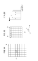
- FIG. 5A to FIG. 5C are schematic explanatory diagrams regarding a method of calculating HOG (Histograms of Oriented Gradient) features. It is a schematic explanatory drawing which shows an example of a integrating
- FIG. 5A to FIG. 5C are schematic explanatory diagrams regarding a method of calculating HOG (Histograms of Oriented Gradient) features. It is a schematic explanatory drawing which shows an example of a integrating
- FIG. 8A is a schematic diagram of an integral image before execution of the thinning process.
- FIG. 8B is a schematic diagram of an integral image after execution of the thinning process.
- 9A to 9C are schematic diagrams representing captured images input to the integration target image creating unit in FIG. It is a schematic explanatory drawing which shows the method of a bit reduction process. It is a schematic explanatory drawing which shows the determination method of an identification object area
- FIG. 1 is a block diagram showing a configuration of an object identification device 10 according to this embodiment.
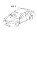
- FIG. 2 is a schematic perspective view of the vehicle 12 on which the object identification device 10 shown in FIG. 1 is mounted.
- the object identification device 10 is a color camera that captures a color image ⁇ hereinafter referred to as a captured image Im (original image) ⁇ composed of a plurality of color channels (hereinafter simply “camera 14”).
- the vehicle speed sensor 16 for detecting the vehicle speed Vs of the vehicle 12
- the yaw rate sensor 18 for detecting the yaw rate Yr of the vehicle 12
- the brake sensor 20 for detecting the brake pedal operation amount Br by the driver
- An electronic control device (hereinafter referred to as “ECU22”) for controlling the identification device 10, a speaker 24 for issuing an alarm or the like by voice, and a display device 26 for displaying a captured image output from the camera 14. .
- the camera 14 is a camera that mainly uses light having a wavelength in the visible light region, and functions as an imaging unit that images the periphery of the vehicle 12.
- the camera 14 has a characteristic that the output signal level increases as the amount of light reflected on the surface of the subject increases, and the luminance (for example, RGB value) of the image increases.
- the camera 14 is fixedly disposed (mounted) at a substantially central portion of the front bumper portion of the vehicle 12.
- the imaging means for imaging the periphery of the vehicle 12 is not limited to the above configuration example (so-called monocular camera), and may be, for example, a compound eye camera (stereo camera). In place of the color camera, a monochrome camera or an infrared camera may be used, or both may be provided. Further, in the case of a monocular camera, another ranging means (radar apparatus) may be provided.
- the speaker 24 outputs an alarm sound or the like in response to a command from the ECU 22.
- the speaker 24 is provided on a dashboard (not shown) of the vehicle 12.
- an audio output function provided in another device (for example, an audio device or a navigation device) may be used.
- the display device 26 (see FIGS. 1 and 2) is a HUD (head-up display) arranged on the front windshield of the vehicle 12 at a position that does not obstruct the driver's front view.
- the display device 26 is not limited to the HUD, but a display that displays a map or the like of a navigation system mounted on the vehicle 12 or a display (MID; multi-information display) that displays fuel consumption or the like provided in a meter unit or the like is used. can do.
- the ECU 22 basically includes an input / output unit 28, a calculation unit 30, a display control unit 32, and a storage unit 34.
- Each signal from the camera 14, the vehicle speed sensor 16, the yaw rate sensor 18, and the brake sensor 20 is input to the ECU 22 side via the input / output unit 28.
- Each signal from the ECU 22 is output to the speaker 24 and the display device 26 via the input / output unit 28.
- the input / output unit 28 includes an A / D conversion circuit (not shown) that converts an input analog signal into a digital signal.
- the calculation unit 30 performs calculations based on the signals from the camera 14, the vehicle speed sensor 16, the yaw rate sensor 18, and the brake sensor 20, and generates signals for the speaker 24 and the display device 26 based on the calculation results.
- the calculation unit 30 includes an integration target image creation unit 40, a data generation unit 42 (data generation unit), a data compression processing unit 44, a data acquisition unit 46 (data acquisition unit), and an identification target region determination unit 48 (identification target region determination unit). ), The object identification unit 50 (object identification unit), and the object detection unit 52.
- each unit in the calculation unit 30 is realized by reading and executing a program stored in the storage unit 34.
- the program may be supplied from the outside via a wireless communication device (mobile phone, smartphone, etc.) not shown.
- the display control unit 32 is a control circuit that drives and controls the display device 26.
- the display control unit 32 drives the display device 26 by outputting a signal used for display control to the display device 26 via the input / output unit 28. Thereby, the display apparatus 26 can display various images (captured image Im, a mark, etc.).
- the storage unit 34 includes an imaging signal converted into a digital signal, a RAM (Random Access Memory) that stores temporary data used for various arithmetic processes, and a ROM (Read Only Memory) that stores an execution program, a table, a map, or the like. ) Etc.
- a RAM Random Access Memory
- ROM Read Only Memory
- the object identification device 10 is basically configured as described above. An outline of the operation of the object identification device 10 will be described below.
- the ECU 22 converts an analog video signal output from the camera 14 into a digital signal at a predetermined frame clock interval / cycle (for example, 30 frames per second) and temporarily captures it in the storage unit 34. Then, the ECU 22 performs various arithmetic processes on the captured image Im (the front image of the vehicle 12) read from the storage unit 34.
- the ECU 22 comprehensively considers the processing results for the captured image Im, and signals (vehicle speed Vs, yaw rate Yr, and operation amount Br) that indicate the traveling state of the vehicle 12 as necessary.
- Vs vehicle speed
- Yr yaw rate
- Br operation amount
- a pedestrian, an animal, or the like existing in front is detected as an object to be monitored (hereinafter referred to as “monitoring object” or simply “object”).
- the ECU 22 controls each output unit of the target identification device 10 in order to call the driver's attention. For example, the ECU 22 outputs an alarm sound (for example, a beeping sound) via the speaker 24 and emphasizes the part of the monitored object in the captured image Im visualized on the display device 26. Display.
- an alarm sound for example, a beeping sound
- the target object identification apparatus 10 in this embodiment is mounted in the vehicle 12 as a moving body, it is not restricted to this form and application.
- a configuration in which captured images are sequentially acquired from a camera 14 fixed to a stationary body including a construction object may be employed.
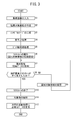
- step S1 the ECU 22 acquires and inputs a captured image Im that is an output signal in front of the vehicle 12 (predetermined angle of view range) captured by the camera 14 for each frame.
- An original image area (hereinafter, referred to as an image area 60) represented by the captured image Im is a rectangular shape that is long in the horizontal direction (for example, the horizontal direction is 1200 pixels and the vertical direction is 600 pixels).
- an image area 60 a road area (hereinafter simply referred to as “road 62”) on which the vehicle 12 travels, and a plurality of utility pole areas (hereinafter simply referred to as “electric pole 64”) installed at substantially equal intervals along the road 62.
- pedestrian areas on the road 62 hereinafter simply referred to as “pedestrian 66”).
- a position on the captured image Im corresponding to a contact point between an actual road surface (road 62) and a human body (pedestrian 66) is set as a reference position 68.
- a rectangular identification target region 70 (a region in a frame illustrated by a broken line) is set according to a predetermined rule using the reference position 68 as a mark.
- the identification target region 70 corresponds to a region of interest in which the presence or absence of an object including the pedestrian 66 is to be identified.
- step S2 the integration target image creating unit 40 creates the integration target image 81-88 from the captured image Im input in step S1.
- HOG Histograms of Oriented ⁇ ⁇ Gradient: gradient direction histogram
- a plurality of blocks 72 are defined by dividing the identification target region 70 into a lattice shape.
- the rectangular identification target area 70 is equally divided two-dimensionally with eight rows and six columns. It is assumed that one block 72 which is a histogram creation unit is selected from the identification target area 70.
- the block 72 is composed of a total of 36 pixels 74, for example, 6 pixels vertically and 6 pixels horizontally.
- a two-dimensional luminance gradient (Ix, Iy) is calculated for each pixel 74 constituting the block 72.
- the luminance gradient intensity I and the luminance gradient angle ⁇ (0 ⁇ ⁇ ⁇ 2 ⁇ ) are calculated according to the following equations (1) and (2).
- I (Ix 2 + Iy 2 ) 1/2
- ⁇ tan ⁇ 1 (Iy / Ix) (2)
- each grid in the first row illustrates the direction of the planar luminance gradient.
- the luminance gradient intensity I and the luminance gradient angle ⁇ are calculated for all the pixels 74, but the illustration of arrows in the second and subsequent rows is omitted.
- a histogram for the luminance gradient angle ⁇ is created for one block 72.
- the horizontal axis of the histogram is the luminance gradient angle ⁇
- the vertical axis of the histogram is the number of pixels.
- the luminance gradient angle ⁇ is divided into the first section (0 ⁇ ⁇ ⁇ / 4), the second section ( ⁇ / 4 ⁇ ⁇ ⁇ / 2),..., And the eighth section (7 ⁇ / 4 ⁇ They are classified into eight sections of ⁇ ⁇ 2 ⁇ ).
- the HOG feature amount in the identification target region 70 is obtained.
- a predetermined order for example, ascending order.
- each value of the HOG feature value changes.
- the amount of calculation becomes enormous because it involves addition and conditional branching for each pixel. Therefore, in order to avoid repeated arithmetic processing, it is convenient to previously create auxiliary intermediate data (an image to be integrated as a feature amount in each pixel 74) used for calculation of the image feature amount.
- each image region 80 represented by the integration target images 81-88 has the same shape, that is, a common size, as the image region 60 (see FIGS. 4A and 4B) represented by the captured image Im.
- the pixels on the integration target image 81-88 respectively corresponding to the positions of the pixels 90 existing in the image area 80 are referred to as corresponding pixels 91-98, respectively.
- the attribute is determined for each pixel 90 according to the luminance gradient angle ⁇ as the image feature amount.
- the pixel 90 belongs to the third section ( ⁇ / 2 ⁇ ⁇ ⁇ 3 ⁇ / 4).
- the integration target image creation unit 40 assigns a pixel value of “1” to the corresponding pixel 93 in the integration target image 83 corresponding to the third category.
- the integration target image creation unit 40 assigns a pixel value of “0” to the corresponding pixels 91, 92, 94-98 among the remaining integration target images 81, 82, 84-88.
- the integration target image creation unit 40 sequentially determines the pixel values of the corresponding pixels 91 to 98 while giving the value “1” alternatively to all the pixels 90 in the image region 80.
- the integration target images 81-88 serve as binary voting data indicating whether or not the first to eighth sections of the histogram are included.
- the value of the luminance gradient intensity I may be considered in addition to the value of the luminance gradient angle ⁇ . For example, the influence of camera noise or the like can be reduced by assigning a value of “1” only when the luminance gradient intensity I is a value equal to or greater than a predetermined threshold (for example, an integer value of 4).
- the integration target images 81-88 are not limited to the above-described voting data, and various definitions may be adopted as long as the image feature amount is for each pixel 74.
- step S3 the data generator 42 generates integral images 101-108 from the integration target images 81-88 created in step S2.
- the “integral image” refers to an image obtained by sequentially integrating pixel values starting from any angular position of the integration target image 81-88 (image region 80).
- pixel values integrated according to the above-described rules are referred to as “integrated pixel values”.
- each image region 100 represented by each integral image 101-108 has the same shape, that is, a common size, as each image region 80 represented by each integration target image 81-88 (see FIG. 6). is doing.
- Each integral image 101-108 is created with a starting point of 110 and an ending point of 112, respectively.
- the integrated pixel value at the position 114 is the sum of the pixel values in the rectangular area with the line segment connecting the starting point 110 and the position 114 as a diagonal line.
- step S4 the data compression processing unit 44 performs a thinning process for reducing the number of pixels of the image on each of the integral images 101-108 generated in step S3.
- the thinning-out process refers to a process of extracting at least every other pixel along at least one direction of the image region 100 (see FIG. 7).
- the data compression processing unit 44 executes the thinning process two-dimensionally, specifically along the X direction and the Y direction orthogonal to the X direction. Direction, or Y direction).
- each integral image 101-108 is composed of a plurality of pixels 120 arranged two-dimensionally, 1200 in the X direction and 600 in the Y direction.
- the data compression processing unit 44 extracts, for example, every 2 pixels (every 3 pixels) along the X direction and every 2 pixels (every 3 pixels) along the Y direction.
- extracted pixels 122 corresponding to 1/9 of the entire pixel 120 are extracted, and thinned pixels 124 corresponding to 8/9 of the entire pixel 120 (rectangular cells without filling). ) are excluded.
- the data compression processing unit 44 has an integral image in which 400 extraction pixels 122 are arranged two-dimensionally in the X direction and 200 in the Y direction ⁇ hereinafter referred to as the first compressed image.
- 131-138 (compressed data) ⁇ is obtained.
- the first compressed images 131-138 are stored in the same or different areas of the storage unit 34 as the memory areas in which the integration target images 81-88 are stored.
- FIGS. 9A to 9C Each figure is a schematic diagram expressing the captured image Im input to the integration target image creation unit 40 of FIG.
- FIG. 9A is a schematic diagram representing the captured image Im when the resolution is not changed.
- the captured image Im appropriately represents a minute part, there is a problem that the amount of data handled in the subsequent identification processing becomes enormous.
- FIG. 9B is a schematic diagram representing the captured image Im after the resolution has been changed to 1/3 times both vertically and horizontally (pixel size is 3 times).
- the data amount of the integral image can be greatly reduced (by about 90%), but a new problem arises in that the information amount of the image itself due to a reduction in resolution is reduced. Specifically, the fine features (luminance gradient intensity I, luminance gradient angle ⁇ ) of the object are lost as the resolution of the original image is reduced.
- FIG. 9C is a schematic diagram representing the captured image Im when the resolution is not changed.
- the fine parts are appropriately expressed as in FIG. 9A.
- the thinning-out process is executed after the integral images 101 to 108 are generated, so that the data amount is greatly reduced (by about 90%), but the accumulated pixel values are substantially the same as those in the case of FIG. 9A. The same minute information can be left. This is because the integral image holds the accumulated pixel value for each pixel, and the accumulated pixel value itself is not affected by the subsequent thinning process.
- the image feature quantity is a histogram
- the integration target images 81-88 are binary voting data indicating whether each of the histograms in each pixel 74 of the captured image Im is binary voting data
- a camera 14 having a high image resolution is usually mounted on the vehicle 12.
- the number of pixels of the integral image tends to increase and the number of effective bits of the data string (pixel value) tends to increase. Especially noticeable.
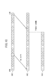
- step S5 the data compression processing unit 44 executes a bit number reduction process for reducing the data amount in units of pixels by at least one bit for each first compressed image 131-138 that has been subjected to the thinning process in step S4. .
- the data string 140 is a binary in which the accumulated pixel value (3 bytes) at the extracted pixel 122 (see FIG. 8A) corresponding to the end point 112 (see FIG. 7) is schematically expressed in binary. It is data.
- the least significant bit (LSB) is referred to as a first bit
- the most significant bit (MSB) is referred to as a 24th bit.
- the value indicated by the data string 140 is the maximum value of the extracted pixels 122. It corresponds to.
- the number of effective bits of the data string 140 is 18 bits, and the values of the 19th to 24th bits are all 0.
- a value of 19.5 bits at maximum can theoretically be taken, but when the distribution of the luminance gradient angle ⁇ is substantially uniform, the maximum value is about 17 bits. It is.
- the data compression processing unit 44 performs a bit shift operation on the data string 140 to obtain a data string 142 in which the 18th bit matches the 24th bit (MSB). After that, as shown in FIG. 10, the data compression processing unit 44 cuts out the lower 8 bits (1 byte) while leaving the upper 16 bits (2 bytes) in the data string 142, so that the effective value is obtained. A 2-byte data string 144 is obtained. Note that by deleting the lower-order bits, an effect of digitally removing electrical noise mixed during imaging with the camera 14 can also be obtained.
- the data compression processing unit 44 may determine the reduction amount of the number of bits according to the data transfer protocol between the arithmetic unit 30 and the storage unit 34. For example, the total amount of data to be transferred can be reduced by reducing the number of bits so that the compressed data string 144 is an integral multiple of the data transfer unit.
- the data compression processing unit 44 obtains an integral image ⁇ hereinafter referred to as a second compressed image 151-158 (compressed data) ⁇ in which the extracted pixels 122 composed of 2-byte integrated pixel values are two-dimensionally arranged.
- the second compressed images 151-158 are stored in the same or different areas of the storage unit 34 as the memory areas in which the first compressed images 131-138 are stored.
- step S6 the arithmetic unit 30 starts a raster scan of the captured image Im.
- the raster scan refers to an object in the captured image Im while moving the reference position 68 (see FIG. 4B; pixels in the captured image Im) by a predetermined amount (scan interval) along the scanning direction.
- the identification target area determination unit 48 sequentially determines the reference position 68 currently being scanned, and the position / size of the identification target area 70 (see FIG. 5) identified from the reference position 68.
- the identification target area determination unit 48 performs initial setting of the reference position 68 and the identification target area 70.
- the data acquisition unit 46 reads and acquires the second compressed images 151-158 from the storage unit 34 in a timely manner.
- the data acquisition unit 46 only needs to directly read out the integrated pixel value of the designated address from the second compressed images 151-158 stored in advance in the storage unit 34, and no separate processing is required.
- the data acquisition unit 46 may perform processing equivalent to the thinning-out processing (see step S4) and / or the bit number reduction processing (see step S5) by the data compression processing unit 44. Good.
- step S7 the object identifying unit 50 identifies whether or not at least one kind of object exists in the determined identification target area 70.
- the data acquisition unit 46 reads and acquires various data (for example, the second compressed images 151-158) necessary for the calculation from the storage unit 34.
- the data acquisition unit 46 is suitable for inputting the data definition unique to the second compressed image 151-158 to the object identification unit 50. Change the data definition accordingly.
- the original data definition may be restored using the reduced number of bits and the bit shift amount (number of bits and direction), or may be obtained without change.
- the object identification unit 50 sequentially obtains the accumulated pixel values of the second compressed images 151-158 corresponding to the block 72, and calculates the number of pixels belonging to the first to eighth sections, respectively. By connecting each value, a histogram corresponding to the block 72 is created. Then, the object identification unit 50 obtains a HOG feature value that is a kind of image feature value in the identification target region 70 by sequentially connecting the histograms for each block 72.
- This image feature quantity may be a brightness feature quantity typified by a Haar-Like feature quantity in addition to an edge feature quantity typified by a HOG feature quantity, regardless of the type or calculation method.
- the object identification unit 50 is an identifier generated using machine learning that receives an image feature amount (for example, HOG feature amount) in the identification target region 70 and outputs the presence / absence information of the object.
- machine learning method any algorithm of supervised learning, unsupervised learning, and reinforcement learning may be employed.
- the learning architecture include a boosting method including AdaBoost, SVM (Support Vector) machine, neural network, EM (Expectation Maximization) algorithm, and the like.
- the types of objects that can be identified include human bodies (pedestrians 66 in FIG. 4A), various animals (specifically, mammals such as deer, horses, sheep, dogs, cats, birds, etc.), artificial A structure (specifically, a vehicle, a sign, a utility pole, a guardrail, a wall, or the like) may be used.
- step S8 the identification target area determination unit 48 determines whether or not all the scans for the designated pixel have been completed. When it is determined that it is not completed (step S8: NO), the process proceeds to the next step (S9).
- the identification target area determination unit 48 changes the position or size of the identification target area 70. Specifically, the identification target region determination unit 48 moves a designated pixel (for example, the reference position 68) that is a scan target by a predetermined amount (for example, three pixels) in a predetermined direction (for example, the right direction).
- a predetermined amount for example, three pixels
- the captured image Im (image region 60) is arranged two-dimensionally, 1200 in the X direction and 600 in the Y direction, like the integration target image 81, the integral image 101, and the like. It is composed of a plurality of pixels 74.
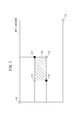
- the identification target area determination unit 48 selects the identification target area 70 (for example, rectangular shape) having at least four referenceable pixels 76 selected from the pixel groups extracted as the second compressed images 151-158. A rectangular parallelepiped).
- the identification target region determination unit 48 changes the scan interval (the number of scans performed) according to the position in the image region 60 in order to further reduce the amount of processing calculation.
- the scan interval at the top of the image area 60 is set to be relatively small (every 3 pixels in both vertical and horizontal directions), and the scan interval at the bottom of the image area 60 is relatively large (in every 6 pixels both vertically and horizontally). To).
- the identification target region determining unit 48 is positioned at the position in the image region 60 (that is, the feature of the captured image Im). By changing the scanning interval accordingly, it is possible to maintain both the identification accuracy of the object in the entire image region 60 and the reduction of the processing calculation amount.
- step S10 the calculation unit 30 sequentially repeats steps S7 to S9 until all scanning of the designated pixel is completed.
- step S8 YES
- the calculation unit 30 ends the raster scan of the captured image Im (step S10).
- step S11 the object detection unit 52 detects an object present in the captured image Im.
- the identification result for a single frame may be used, or the motion vector for the same object can be calculated by considering the identification results for a plurality of frames.
- step S12 the ECU 22 causes the storage unit 34 to store data necessary for the next calculation process.
- the attributes of the object (pedestrian 66 in FIG. 4A) obtained in step S7, the reference position 68, and the like can be given.
- the object identification device 10 can monitor an object existing in front of the vehicle 12 at a predetermined time interval.
- the object identification device 10 includes the data generation unit 42 that generates the integral image 101-108 having the image area 100 having the same size as the captured image Im and the integration target image 81-88. , Compressed data obtained by extracting at least every other pixel (extracted pixel 122) along at least one direction from the plurality of pixels 120 constituting the integral image 101-108 (first compressed data 131-138, The data acquisition unit 46 for obtaining the second compressed data 151-158), the identification target region determination unit 48 for determining the identification target region 70 from the image region 60, and the above-mentioned compressed data, The sum of the pixel values of the integration target images 81-88 is calculated as an image feature amount, and an object (example) If, whether pedestrians 66) is present and a target identification unit 50 identifies, based on the image feature amount.
- the first compressed image 131-138 in which the original information of the integration target images 81-88 at the position of each extraction pixel 122 is stored as it is is obtained.
- the stored image information it is possible to maintain the identification accuracy of the object while greatly reducing the data amount of the integral images 101-108.
- the above-described image processing is executed on the captured image Im obtained by the monocular camera (camera 14), but the same effect can be obtained even with a compound eye camera (stereo camera).
- the image area represented by the original image may be not only a planar area (two-dimensional) but also a three-dimensional area (three-dimensional) or an image area including the concept of time.
Landscapes
- Engineering & Computer Science (AREA)
- Multimedia (AREA)
- Physics & Mathematics (AREA)
- General Physics & Mathematics (AREA)
- Theoretical Computer Science (AREA)
- Mechanical Engineering (AREA)
- Computer Vision & Pattern Recognition (AREA)
- Human Computer Interaction (AREA)
- Image Analysis (AREA)
- Image Processing (AREA)
- Traffic Control Systems (AREA)
Description
I=(Ix2+Iy2)1/2 ‥(1)
θ=tan-1(Iy/Ix) ‥(2)
Claims (7)
- 原画像(Im)を構成する各画素(74)における特徴量としての積算対象画像(81-88)に関し、前記積算対象画像(81-88)のいずれかの角位置を起点(110)として画素値を順次積算することで、前記原画像(Im)及び前記積算対象画像(81-88)と共通するサイズの画像領域(100)を有するインテグラルイメージ(101-108)を生成するデータ生成部(42)と、
前記データ生成部(42)により生成された前記インテグラルイメージ(101-108)を構成する複数の画素(120)の中から、少なくとも一方向に沿って少なくとも1つおきに画素(122)をそれぞれ抽出した圧縮データ(131-138、151-158)を取得するデータ取得部(46)と、
前記原画像(Im)が表す原画像領域(60)の中から識別対象領域(70)を決定する識別対象領域決定部(48)と、
前記データ取得部(46)により取得された前記圧縮データ(131-138、151-158)を用いて、前記識別対象領域決定部(48)により決定された前記識別対象領域(70)での前記積算対象画像(81-88)の画素値の総和を画像特徴量として算出し、前記原画像(Im)の前記識別対象領域(70)内に対象物(66)が存在するか否かを前記画像特徴量に基づいて識別する対象物識別部(50)と
を備えることを特徴とする対象物識別装置(10)。 - 請求項1記載の装置(10)において、
前記識別対象領域決定部(48)は、前記圧縮データ(131-138、151-158)として抽出された画素群の中からそれぞれ選択した、少なくとも4つの画素(76)を頂点とする前記識別対象領域(70)を決定することを特徴とする対象物識別装置(10)。 - 請求項1又は2に記載の装置(10)において、
前記データ取得部(46)は、前記インテグラルイメージ(101-108)の画素単位のデータ量を少なくとも1ビット削減して前記圧縮データ(151-158)を取得することを特徴とする対象物識別装置(10)。 - 請求項1~3のいずれか1項に記載の装置(10)において、
前記識別対象領域(70)の位置を走査方向に沿ってスキャン間隔だけ遂次変更させながら、前記識別対象領域決定部(48)による決定及び前記対象物識別部(50)による識別を順次実行することで、前記原画像(Im)の中に前記対象物(66)が存在するか否かを識別する場合、
前記識別対象領域決定部(48)は、前記原画像領域(60)内の位置に応じて前記スキャン間隔を異ならせて前記識別対象領域(70)を決定する
ことを特徴とする対象物識別装置(10)。 - 請求項4記載の装置(10)において、
車両(12)に搭載され、前記車両(12)の走行中に撮像することで前記車両(12)の周辺における撮像画像を取得する撮像部(14)をさらに備え、
前記撮像部(14)により前記原画像(Im)として取得された前記撮像画像に関し、前記原画像領域(60)内の下部の位置における前記スキャン間隔を、前記原画像領域(60)内の上部の位置における前記スキャン間隔よりも大きくする
ことを特徴とする対象物識別装置(10)。 - 請求項1~4のいずれか1項に記載の装置(10)において、
前記画像特徴量はヒストグラムであり、
前記積算対象画像(81-88)は、前記原画像(Im)の各画素(74)における前記ヒストグラムの各区分の属否を示す2値の投票データである
ことを特徴とする対象物識別装置(10)。 - 請求項6記載の装置(10)において、
車両(12)に搭載され、前記車両(12)の走行中に撮像することで前記原画像(Im)としての撮像画像を取得する撮像部(14)をさらに備えることを特徴とする対象物識別装置(10)。
Priority Applications (3)
| Application Number | Priority Date | Filing Date | Title |
|---|---|---|---|
| JP2014535404A JP5856682B2 (ja) | 2012-09-14 | 2013-06-20 | 対象物識別装置 |
| US14/428,035 US9292751B2 (en) | 2012-09-14 | 2013-06-20 | Object identifier |
| CN201380047416.2A CN104620285B (zh) | 2012-09-14 | 2013-06-20 | 对象物识别装置 |
Applications Claiming Priority (2)
| Application Number | Priority Date | Filing Date | Title |
|---|---|---|---|
| JP2012202397 | 2012-09-14 | ||
| JP2012-202397 | 2012-09-14 |
Publications (1)
| Publication Number | Publication Date |
|---|---|
| WO2014041864A1 true WO2014041864A1 (ja) | 2014-03-20 |
Family
ID=50277998
Family Applications (1)
| Application Number | Title | Priority Date | Filing Date |
|---|---|---|---|
| PCT/JP2013/066972 Ceased WO2014041864A1 (ja) | 2012-09-14 | 2013-06-20 | 対象物識別装置 |
Country Status (4)
| Country | Link |
|---|---|
| US (1) | US9292751B2 (ja) |
| JP (1) | JP5856682B2 (ja) |
| CN (1) | CN104620285B (ja) |
| WO (1) | WO2014041864A1 (ja) |
Cited By (4)
| Publication number | Priority date | Publication date | Assignee | Title |
|---|---|---|---|---|
| CN105607254A (zh) * | 2014-11-13 | 2016-05-25 | 威斯通全球技术公司 | 调适透明电子显示器上的显示 |
| EP3176752A4 (en) * | 2014-07-28 | 2018-03-28 | Clarion Co., Ltd. | Object detecting device |
| WO2020246012A1 (ja) * | 2019-06-06 | 2020-12-10 | 日本電信電話株式会社 | 画像処理装置、変換装置、画像処理方法、変換方法、及びプログラム |
| WO2022102221A1 (ja) * | 2020-11-16 | 2022-05-19 | 日立Astemo株式会社 | Dnn縮約装置及び車載演算装置 |
Families Citing this family (12)
| Publication number | Priority date | Publication date | Assignee | Title |
|---|---|---|---|---|
| KR101503788B1 (ko) * | 2013-12-27 | 2015-03-19 | 숭실대학교산학협력단 | 적분영상을 기반으로 하는 특징 정보 예측을 통한 보행자 검출 방법, 이를 수행하기 위한 기록 매체 및 단말기 |
| JP6253467B2 (ja) * | 2014-03-24 | 2017-12-27 | 東芝アルパイン・オートモティブテクノロジー株式会社 | 画像処理装置および画像処理プログラム |
| US9569851B2 (en) | 2014-12-23 | 2017-02-14 | Ricoh Co., Ltd. | Sequencing products recognized in a shelf image |
| US9342900B1 (en) * | 2014-12-23 | 2016-05-17 | Ricoh Co., Ltd. | Distinguishing between stock keeping units using marker based methodology |
| US9619899B2 (en) | 2014-12-23 | 2017-04-11 | Ricoh Co., Ltd. | Distinguishing between stock keeping units using hough voting methodology |
| US9454904B1 (en) * | 2015-03-16 | 2016-09-27 | Ford Global Technologies, Llc | Safety pedal obstruction and command intention detection |
| KR102407624B1 (ko) * | 2015-10-06 | 2022-06-10 | 삼성전자주식회사 | 전자 장치의 영상 처리 방법 및 그 전자 장치 |
| CN105224930B (zh) * | 2015-10-19 | 2018-03-06 | 广东欧珀移动通信有限公司 | 一种指纹识别的方法和装置 |
| CN107368835B (zh) * | 2016-05-12 | 2020-11-03 | 北京君正集成电路股份有限公司 | 一种获取像素点的积分和的方法及装置 |
| CN107368834A (zh) * | 2016-05-12 | 2017-11-21 | 北京君正集成电路股份有限公司 | 一种方向梯度积分图存储方法及装置 |
| CN108875535B (zh) * | 2018-02-06 | 2023-01-10 | 北京旷视科技有限公司 | 图像检测方法、装置和系统及存储介质 |
| CN114419312B (zh) * | 2022-03-31 | 2022-07-22 | 南京智谱科技有限公司 | 图像处理方法及装置、计算设备和计算机可读存储介质 |
Citations (3)
| Publication number | Priority date | Publication date | Assignee | Title |
|---|---|---|---|---|
| JP2010108262A (ja) * | 2008-10-30 | 2010-05-13 | Canon Inc | オブジェクト検出装置およびその制御方法 |
| JP2010170202A (ja) * | 2009-01-20 | 2010-08-05 | Secom Co Ltd | 物体検出装置 |
| JP2011134102A (ja) * | 2009-12-24 | 2011-07-07 | Canon Inc | 情報処理装置及び情報処理方法 |
Family Cites Families (9)
| Publication number | Priority date | Publication date | Assignee | Title |
|---|---|---|---|---|
| US7164117B2 (en) * | 1992-05-05 | 2007-01-16 | Automotive Technologies International, Inc. | Vehicular restraint system control system and method using multiple optical imagers |
| JPS62247410A (ja) * | 1985-12-04 | 1987-10-28 | Aisin Seiki Co Ltd | 電気装置の付勢制御装置 |
| EP2267656A3 (en) * | 1998-07-31 | 2012-09-26 | Panasonic Corporation | Image displaying apparatus und image displaying method |
| JP4818609B2 (ja) * | 2002-08-21 | 2011-11-16 | ジェンテックス コーポレイション | 外部車両照明の自動制御のための画像取得及び処理方法 |
| US7671725B2 (en) * | 2006-03-24 | 2010-03-02 | Honda Motor Co., Ltd. | Vehicle surroundings monitoring apparatus, vehicle surroundings monitoring method, and vehicle surroundings monitoring program |
| JP4582079B2 (ja) | 2006-10-19 | 2010-11-17 | トヨタ自動車株式会社 | 画像識別装置および画像識別方法 |
| CN100472564C (zh) * | 2007-04-30 | 2009-03-25 | 北京中星微电子有限公司 | 一种图像跟踪方法及系统 |
| CN100561505C (zh) * | 2007-12-05 | 2009-11-18 | 北京中星微电子有限公司 | 一种图像检测方法及装置 |
| CN102663778B (zh) * | 2012-04-26 | 2015-12-02 | 安科智慧城市技术(中国)有限公司 | 一种基于多视点视频的目标跟踪方法和系统 |
-
2013
- 2013-06-20 WO PCT/JP2013/066972 patent/WO2014041864A1/ja not_active Ceased
- 2013-06-20 CN CN201380047416.2A patent/CN104620285B/zh active Active
- 2013-06-20 US US14/428,035 patent/US9292751B2/en active Active
- 2013-06-20 JP JP2014535404A patent/JP5856682B2/ja not_active Expired - Fee Related
Patent Citations (3)
| Publication number | Priority date | Publication date | Assignee | Title |
|---|---|---|---|---|
| JP2010108262A (ja) * | 2008-10-30 | 2010-05-13 | Canon Inc | オブジェクト検出装置およびその制御方法 |
| JP2010170202A (ja) * | 2009-01-20 | 2010-08-05 | Secom Co Ltd | 物体検出装置 |
| JP2011134102A (ja) * | 2009-12-24 | 2011-07-07 | Canon Inc | 情報処理装置及び情報処理方法 |
Cited By (8)
| Publication number | Priority date | Publication date | Assignee | Title |
|---|---|---|---|---|
| EP3176752A4 (en) * | 2014-07-28 | 2018-03-28 | Clarion Co., Ltd. | Object detecting device |
| CN105607254A (zh) * | 2014-11-13 | 2016-05-25 | 威斯通全球技术公司 | 调适透明电子显示器上的显示 |
| WO2020246012A1 (ja) * | 2019-06-06 | 2020-12-10 | 日本電信電話株式会社 | 画像処理装置、変換装置、画像処理方法、変換方法、及びプログラム |
| JPWO2020246012A1 (ja) * | 2019-06-06 | 2020-12-10 | ||
| JP7332941B2 (ja) | 2019-06-06 | 2023-08-24 | 日本電信電話株式会社 | 画像処理装置、変換装置、画像処理方法、変換方法、及びプログラム |
| US12086952B2 (en) | 2019-06-06 | 2024-09-10 | Nippon Telegraph And Telephone Corporation | Image processing apparatus, conversion apparatus, image processing method, conversion method and program |
| WO2022102221A1 (ja) * | 2020-11-16 | 2022-05-19 | 日立Astemo株式会社 | Dnn縮約装置及び車載演算装置 |
| JP7469508B2 (ja) | 2020-11-16 | 2024-04-16 | 日立Astemo株式会社 | Dnn縮約装置及び車載演算装置 |
Also Published As
| Publication number | Publication date |
|---|---|
| US20150242694A1 (en) | 2015-08-27 |
| US9292751B2 (en) | 2016-03-22 |
| CN104620285B (zh) | 2017-04-12 |
| CN104620285A (zh) | 2015-05-13 |
| JP5856682B2 (ja) | 2016-02-10 |
| JPWO2014041864A1 (ja) | 2016-08-18 |
Similar Documents
| Publication | Publication Date | Title |
|---|---|---|
| JP5856682B2 (ja) | 対象物識別装置 | |
| JP5922257B2 (ja) | 車両周辺監視装置 | |
| US10783382B2 (en) | Systems and methods for buffer-free lane detection | |
| JP2014106685A (ja) | 車両周辺監視装置 | |
| EP4332910A1 (en) | Behavior detection method, electronic device, and computer readable storage medium | |
| CN114750696B (zh) | 车辆视觉呈现的方法、车载设备及车辆 | |
| CN112364693B (zh) | 基于双目视觉的障碍识别方法、装置、设备及存储介质 | |
| CN109063603A (zh) | 基于区域动态筛选的图像预测方法和装置及电子设备 | |
| CN114092771A (zh) | 多传感数据融合方法、目标检测方法、装置和计算机设备 | |
| CN117292346B (zh) | 面向驾驶人和车辆状态一体感知的车辆行驶风险预警方法 | |
| JP2019139420A (ja) | 立体物認識装置、撮像装置および車両 | |
| CN111191682A (zh) | 网络模型训练方法、黑夜图像的目标检测方法及相关设备 | |
| KR20260026570A (ko) | 이미지 처리를 위한 방법들 및 시스템들과 이의 저장 매체들 | |
| CN115346184A (zh) | 一种车道信息检测方法、终端及计算机存储介质 | |
| CN111160206A (zh) | 一种交通环境元素视觉感知方法及装置 | |
| CN114120056B (zh) | 小目标识别方法、装置、电子设备、介质及产品 | |
| JP2018092603A (ja) | 情報処理装置、撮像装置、機器制御システム、移動体、情報処理方法、及び、情報処理プログラム | |
| CN112560802A (zh) | 可分配数据存储库的数据处理方法及系统 | |
| CN116703940A (zh) | 车辆三维场景分割方法、系统、相关装置和车辆 | |
| CN114495039B (zh) | 对象识别方法、装置、电子设备及存储介质 | |
| CN116168419B (zh) | 一种红外人体检测方法、装置及机器人 | |
| CN120726610B (zh) | 障碍物检测方法、障碍物检测模型训练方法及电子设备 | |
| CN117576661A (zh) | 行人检测方法、装置、电子设备和存储介质 | |
| CN117115428A (zh) | 基于相机的目标检测方法、装置、设备及存储介质 | |
| KR20250106038A (ko) | 차량 제어 장치 및 그 방법 |
Legal Events
| Date | Code | Title | Description |
|---|---|---|---|
| 121 | Ep: the epo has been informed by wipo that ep was designated in this application |
Ref document number: 13836944 Country of ref document: EP Kind code of ref document: A1 |
|
| ENP | Entry into the national phase |
Ref document number: 2014535404 Country of ref document: JP Kind code of ref document: A |
|
| WWE | Wipo information: entry into national phase |
Ref document number: 14428035 Country of ref document: US |
|
| NENP | Non-entry into the national phase |
Ref country code: DE |
|
| 122 | Ep: pct application non-entry in european phase |
Ref document number: 13836944 Country of ref document: EP Kind code of ref document: A1 |