WO2014034776A1 - Method for manufacturing absorptive article - Google Patents
Method for manufacturing absorptive article Download PDFInfo
- Publication number
- WO2014034776A1 WO2014034776A1 PCT/JP2013/073133 JP2013073133W WO2014034776A1 WO 2014034776 A1 WO2014034776 A1 WO 2014034776A1 JP 2013073133 W JP2013073133 W JP 2013073133W WO 2014034776 A1 WO2014034776 A1 WO 2014034776A1
- Authority
- WO
- WIPO (PCT)
- Prior art keywords
- absorbent
- core
- lower layer
- absorber
- absorbent core
- Prior art date
Links
Images


Classifications
-
- A—HUMAN NECESSITIES
- A61—MEDICAL OR VETERINARY SCIENCE; HYGIENE
- A61F—FILTERS IMPLANTABLE INTO BLOOD VESSELS; PROSTHESES; DEVICES PROVIDING PATENCY TO, OR PREVENTING COLLAPSING OF, TUBULAR STRUCTURES OF THE BODY, e.g. STENTS; ORTHOPAEDIC, NURSING OR CONTRACEPTIVE DEVICES; FOMENTATION; TREATMENT OR PROTECTION OF EYES OR EARS; BANDAGES, DRESSINGS OR ABSORBENT PADS; FIRST-AID KITS
- A61F13/00—Bandages or dressings; Absorbent pads
- A61F13/15—Absorbent pads, e.g. sanitary towels, swabs or tampons for external or internal application to the body; Supporting or fastening means therefor; Tampon applicators
- A61F13/15577—Apparatus or processes for manufacturing
- A61F13/15617—Making absorbent pads from fibres or pulverulent material with or without treatment of the fibres
- A61F13/15634—Making fibrous pads between sheets or webs
-
- A—HUMAN NECESSITIES
- A61—MEDICAL OR VETERINARY SCIENCE; HYGIENE
- A61F—FILTERS IMPLANTABLE INTO BLOOD VESSELS; PROSTHESES; DEVICES PROVIDING PATENCY TO, OR PREVENTING COLLAPSING OF, TUBULAR STRUCTURES OF THE BODY, e.g. STENTS; ORTHOPAEDIC, NURSING OR CONTRACEPTIVE DEVICES; FOMENTATION; TREATMENT OR PROTECTION OF EYES OR EARS; BANDAGES, DRESSINGS OR ABSORBENT PADS; FIRST-AID KITS
- A61F13/00—Bandages or dressings; Absorbent pads
- A61F13/15—Absorbent pads, e.g. sanitary towels, swabs or tampons for external or internal application to the body; Supporting or fastening means therefor; Tampon applicators
- A61F13/45—Absorbent pads, e.g. sanitary towels, swabs or tampons for external or internal application to the body; Supporting or fastening means therefor; Tampon applicators characterised by the shape
- A61F13/47—Sanitary towels, incontinence pads or napkins
- A61F13/472—Sanitary towels, incontinence pads or napkins specially adapted for female use
-
- A—HUMAN NECESSITIES
- A61—MEDICAL OR VETERINARY SCIENCE; HYGIENE
- A61F—FILTERS IMPLANTABLE INTO BLOOD VESSELS; PROSTHESES; DEVICES PROVIDING PATENCY TO, OR PREVENTING COLLAPSING OF, TUBULAR STRUCTURES OF THE BODY, e.g. STENTS; ORTHOPAEDIC, NURSING OR CONTRACEPTIVE DEVICES; FOMENTATION; TREATMENT OR PROTECTION OF EYES OR EARS; BANDAGES, DRESSINGS OR ABSORBENT PADS; FIRST-AID KITS
- A61F13/00—Bandages or dressings; Absorbent pads
- A61F13/15—Absorbent pads, e.g. sanitary towels, swabs or tampons for external or internal application to the body; Supporting or fastening means therefor; Tampon applicators
- A61F13/53—Absorbent pads, e.g. sanitary towels, swabs or tampons for external or internal application to the body; Supporting or fastening means therefor; Tampon applicators characterised by the absorbing medium
- A61F13/534—Absorbent pads, e.g. sanitary towels, swabs or tampons for external or internal application to the body; Supporting or fastening means therefor; Tampon applicators characterised by the absorbing medium having an inhomogeneous composition through the thickness of the pad
- A61F13/535—Absorbent pads, e.g. sanitary towels, swabs or tampons for external or internal application to the body; Supporting or fastening means therefor; Tampon applicators characterised by the absorbing medium having an inhomogeneous composition through the thickness of the pad inhomogeneous in the plane of the pad, e.g. core absorbent layers being of different sizes
- A61F13/536—Absorbent pads, e.g. sanitary towels, swabs or tampons for external or internal application to the body; Supporting or fastening means therefor; Tampon applicators characterised by the absorbing medium having an inhomogeneous composition through the thickness of the pad inhomogeneous in the plane of the pad, e.g. core absorbent layers being of different sizes having discontinuous areas of compression
-
- A—HUMAN NECESSITIES
- A61—MEDICAL OR VETERINARY SCIENCE; HYGIENE
- A61F—FILTERS IMPLANTABLE INTO BLOOD VESSELS; PROSTHESES; DEVICES PROVIDING PATENCY TO, OR PREVENTING COLLAPSING OF, TUBULAR STRUCTURES OF THE BODY, e.g. STENTS; ORTHOPAEDIC, NURSING OR CONTRACEPTIVE DEVICES; FOMENTATION; TREATMENT OR PROTECTION OF EYES OR EARS; BANDAGES, DRESSINGS OR ABSORBENT PADS; FIRST-AID KITS
- A61F13/00—Bandages or dressings; Absorbent pads
- A61F13/15—Absorbent pads, e.g. sanitary towels, swabs or tampons for external or internal application to the body; Supporting or fastening means therefor; Tampon applicators
- A61F13/53—Absorbent pads, e.g. sanitary towels, swabs or tampons for external or internal application to the body; Supporting or fastening means therefor; Tampon applicators characterised by the absorbing medium
- A61F13/534—Absorbent pads, e.g. sanitary towels, swabs or tampons for external or internal application to the body; Supporting or fastening means therefor; Tampon applicators characterised by the absorbing medium having an inhomogeneous composition through the thickness of the pad
- A61F13/535—Absorbent pads, e.g. sanitary towels, swabs or tampons for external or internal application to the body; Supporting or fastening means therefor; Tampon applicators characterised by the absorbing medium having an inhomogeneous composition through the thickness of the pad inhomogeneous in the plane of the pad, e.g. core absorbent layers being of different sizes
- A61F2013/5355—Absorbent pads, e.g. sanitary towels, swabs or tampons for external or internal application to the body; Supporting or fastening means therefor; Tampon applicators characterised by the absorbing medium having an inhomogeneous composition through the thickness of the pad inhomogeneous in the plane of the pad, e.g. core absorbent layers being of different sizes with terraced core
Definitions
- the present invention relates to a method for producing absorbent articles such as sanitary napkins and incontinence pads.
- the applicant first comprises an absorber having an upper layer absorber on the skin facing surface side and a lower layer absorber on the non-skin facing surface side, and when the absorber is viewed in plan view,
- the sanitary napkin which arranged regularly the compression point formed by compressing an upper layer absorber and a lower layer absorber in the thickness direction was proposed (refer to patent documents 2).
- the core wrap sheet that wraps the absorbent core constituting the absorbent body may be torn. It was. If the core wrap sheet can be prevented from being torn, the convex part of the roll forming the compression part or the compression point can be easily removed from the absorbent body during the production of the sanitary napkin, and the sanitary napkin can be stably produced. Can be expected. In addition, if the core wrap sheet can be prevented from being torn, the absorbent body composed of the absorbent core and the core wrap sheet is further integrated, making the absorbent body difficult to twist when worn, and further improvement in fit to the body is expected. it can.
- the present invention relates to a method for producing an absorbent article that is hard to be broken in a core wrap sheet when a compressed portion or a compression point is formed on an absorbent body by pressing with a convex portion of a roll.
- the manufacturing method of an absorbent article of the present invention is a manufacturing method of an absorbent article provided with an absorbent body in which an absorbent core is wrapped with a core wrap sheet, wherein the absorbent body is partly raised in the thickness direction.
- a continuous body of the absorbent body is supplied between a convex roll and a flat roll having a plurality of convex portions on a peripheral surface, and the convex portions of the absorbent body are supplied by the convex portions.
- seat enter to the inside of this protruding part is provided.
- Each convex part used for the concave part forming step has a tip part projecting stepwise, and has a projecting part at the tip part.
- the width (W1) of the projecting part and the tip of the projecting part The relationship with the protrusion height (h) is W1 ⁇ h.
- the absorbent article of the present invention is an absorbent article including an absorbent body in which an absorbent core is wrapped with a core wrap sheet, and the absorbent body has a raised portion that is partially raised in the thickness direction.
- the absorber has a plurality of the recesses that have entered the inside of the raised portion of the absorber.
- the core wrap sheet has a sheet that covers the non-skin facing side of the absorbent core, separate from the sheet that covers the skin facing side of the absorbent core, and covers the non-skin facing side. The sheet to be inserted penetrates into the raised portion in the concave portion.
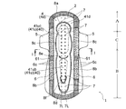
- FIG. 1 is a plan view showing a sanitary napkin obtained by an embodiment of the present invention.
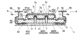
- 2 is a cross-sectional view taken along the line II shown in FIG.
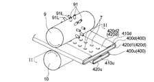
- FIG. 3 is a schematic perspective view showing a pair of convex rolls and flat rolls suitably used for carrying out the manufacturing method according to the embodiment of the present invention.
- FIG. 4 is an enlarged perspective view of a convex portion provided in the convex roll shown in FIG. 3. It is the schematic which looked at a pair of convex roll and flat roll which are shown in FIG. 5, FIG. 3 from the side. 6 is a cross-sectional view taken along the line II-II shown in FIG.
- FIG. 7 is an explanatory diagram when the concave portion is formed by the convex portion provided in the convex roll shown in FIG. 3.
- the manufacturing method of the absorbent article of this invention and the absorbent article of this invention are demonstrated, referring drawings based on the preferable embodiment.
- a sanitary napkin manufactured by the manufacturing method of this embodiment and a sanitary napkin which is an absorbent article of the present invention will be described with reference to FIGS.
- the sanitary napkin 1 has a vertically long shape.
- To the front of the excretory part facing area C, which is a part facing the excretion part of the wearer when worn, and the excretory part facing area C It has a front area A that extends and a rear area B that extends rearward of the excretory part facing area C.
- the sanitary napkin 1 has a liquid-permeable surface sheet 2 located on the skin-facing surface side disposed on the skin side of the wearer when worn, and a wearer when worn, as shown in FIG. 2.
- a liquid-impermeable or liquid-impermeable back sheet 3 located on the non-skin facing surface side, which is disposed on the opposite side to the skin side. Between the top sheet 2 and the back sheet 3, a liquid-retaining vertically long absorbent body 4 is disposed.
- the sanitary napkin 1 has a pair of wing portions 5 and 5 extending in the excretion portion facing area C from the left and right side portions to the side.
- the wing part 5 is formed as an extended portion of the back sheet 3 and / or the top sheet 2, or is formed from a member different from the back sheet 3 and the top sheet 2.
- An adhesive layer (not shown) is provided on the non-skin facing surface of the back sheet 3 and the wing part 5. The pressure-sensitive adhesive layer is used to fix the sanitary napkin 1 to the shorts when the sanitary napkin 1 is attached to the wearer's shorts.
- the sanitary napkin 1 is provided with a pair of leak-proof cuffs 6 extending in the vertical direction of the sanitary napkin 1 on the left and right side portions on the surface sheet 2 side. .
- the leak-proof cuff 6 is composed of a wall portion 6a that stands upward and an overhanging portion 6b that projects horizontally from the upper end of the wall portion 6a.
- the transverse cross section of the leak-proof cuff 6 has a substantially T-shape.
- the base of the wall 6 a is located between the absorber 4 and the back sheet 3.
- the overhanging portion 6b has a substantially flat upper surface so that when the sanitary napkin 1 is worn, the overhanging portion 6b comes into contact with the skin of the wearer.
- a plurality of elastic yarns 6c extending in the same direction as the direction in which the leak-proof cuff 6 extends are arranged in the overhanging portion 6b.
- the elastic yarn 6c is fixed to the overhanging portion 6b in an elongated state in the vertical direction.
- the elastic yarn 6c erects the wall portion 6a by contraction thereof, stabilizes the planar shape of the overhang portion 6b, and ensures contact of the overhang portion 6b with the skin.
- the overhanging portion 6 b is joined to the topsheet 2 at the position of the front end and the rear end in the vertical direction of the sanitary napkin 1. Further, the overhanging portion 6b is joined to the topsheet 2 also at the intermediate fixing portion 61 that is in the vicinity of the boundary portion with the excretory portion facing region C in the rear end region B of the sanitary napkin 1. By these joining, the leak-proof cuff 6 becomes more stable in standing.
- the absorbent body 4 included in the sanitary napkin 1 is formed by wrapping an absorbent core 41 with a core wrap sheet 42, and has a raised portion 40 that is partially raised in the thickness direction.
- the absorbent body 4 has a two-layer structure including a lower layer absorbent body 4d and an upper layer absorbent body 4u on the lower layer absorbent body 4d, as shown in FIGS.
- the upper-layer absorber 4u is formed to have a smaller width than the lower-layer absorber 4d, and the upper-layer absorber 4u is overlapped with the lateral central region of the lower-layer absorber 4d.
- the upper layer absorber 4u and the lower layer absorber 4d are formed with the same length.
- the absorbent core 41 includes a lower layer absorbent core 41d constituting the lower layer absorber 4d and an upper layer absorbent core 41u constituting the upper layer absorber 4u.
- the raised portion 40 is formed by the upper absorbent core 41u of the upper absorbent body 4u.
- the absorbent body 4 having the raised portion 40 is formed using the absorbent core 41 having a thickness difference partially raised in the thickness direction.
- the upper absorbent core 41u of the upper absorbent body 4u includes the upper absorbent core 41uc of the excretory part opposing region C disposed in the excretory part opposing region C and the rear region B.
- the absorbent core 41 has an upper layer of the excretory part facing region C in the lateral central region on the skin facing surface side of the lower layer absorbent core 41d disposed from the front region A to the rear region B.
- the absorbent core 41uc and the upper layer absorbent core 41ub in the rear region B are spaced apart in the vertical direction, and the sanitary napkin 1 is spaced apart in the vertical direction to form an absorbent core 41 having a thickness difference. ing. That is, the raised portions 40 are formed at intervals in the longitudinal direction of the sanitary napkin 1.
- the contour of the lower absorbent core 41d defines the contour of the absorbent core 41.
- the core wrap sheet 42 has a sheet that covers the non-skin facing surface side of the absorbent core 41, which is separate from the sheet that covers the skin facing surface side of the absorbent core 41.
- the sanitary napkin 1 has a lower layer core wrap sheet 42d that wraps the lower layer absorbent core 41d and an upper layer core wrap sheet 42u that wraps the upper layer absorbent core 41u.
- the lower layer core wrap sheet 42d is a first lower layer core wrap that covers the skin facing surface side of the lower layer absorbent core 41d (the surface side close to the upper layer absorbent core 41u) as shown in FIG.
- the sheet 42d1 and the second lower layer core wrap sheet 42d2 that covers the non-skin facing surface side (the surface side far from the upper layer absorbent core 41u) of the lower layer absorbent core 41d are provided.
- the sheet covering the non-skin facing surface side corresponds to the second lower layer core wrap sheet 42d2.
- the first lower layer core wrap sheet 42d1 is longer in the lateral direction than the lateral length of the lower layer absorbent core 41d.
- the first lower layer core wrap sheet 42d1 covers the entire area of the skin facing surface of the lower layer absorbent core 41d (surface close to the upper layer absorbent core 41u), and both left and right side portions of the lower layer absorbent core 41d.
- Each of the portions extending from the side to the side is folded to the non-skin-opposing surface side of the lower layer absorbent core 41d (the surface side far from the upper layer absorbent core 41u), and each of the folded tip portions is the lower layer absorbent core
- the left and right sides of the second lower layer core wrap sheet 42d2 covering the non-skin facing surface of 41d (the surface far from the upper layer absorbent core 41u) are covered, and the first lower layer core wrap sheet 42d1 and the second lower layer core wrap sheet 42d2 are covered. Is disposed on the non-skin facing surface side of the absorbent body 4.
- the first lower layer core wrap sheet 42d1 and the second lower layer core wrap sheet 42d2 are not joined at the overlapping portions 43 on the left and right side portions.
- the lower layer absorbent body 4d is formed of a lower layer absorbent core 41d and a lower layer core wrap sheet 42d (a first lower layer core wrap sheet 42d1 and a second lower layer core wrap sheet 42d2) that wraps the lower layer absorbent core 41d.
- the upper layer core wrap sheet 42u has a lateral length longer than the lateral length of the upper absorbent core 41u.
- the upper layer core wrap sheet 42u covers the entire skin-facing surface of the upper layer absorbent core 41u (the surface far from the lower layer absorbent core 41d) as shown in FIG.
- Each of the portions extending from the left and right side portions of 41u to the side is folded to the non-skin facing surface side (surface side close to the lower layer absorbent core 41d) of the upper layer absorbent core 41u, and the folded tip portions are respectively , Are overlapping.
- the upper absorbent core 41u is wrapped with the upper core wrap sheet 42u.
- the upper layer absorbent body 4u is formed of an upper layer absorbent core 41u (upper layer absorbent core 41uc and upper layer absorbent core 41ub) and an upper layer core wrap sheet 42u that wraps the upper layer absorbent core 41u.
- the upper absorbent core 41u wrapped by the upper core wrap sheet 42u and the lower absorbent core 41d wrapped by the first lower core wrap sheet 42d1 and the second lower core wrap sheet 42d2 As shown in FIG. 2, it is fixed by an adhesive 11 such as a hot-melt adhesive.
- an adhesive 11 such as a hot-melt adhesive.
- the upper layer core wrap sheet 42u and the upper layer absorbent core 41u are not fixed by an adhesive, and the first lower layer core wrap sheet 42d1 and the second lower layer core wrap sheet 42d2 are used.
- the lower absorbent core 41d is not fixed by an adhesive, and the overlapping portion between the first lower core wrap sheet 42d1 and the second lower core wrap sheet 42d2 is not fixed by the adhesive.
- the adhesive 11 is applied between the first lower-layer core wrap sheet 42d1 and the upper-layer core wrap sheet 42u, and the upper-layer absorbent body 4u and the lower-layer absorbent body 4d are fixed, and the absorbent body of the sanitary napkin 1 4 is formed. Moreover, the skin facing surface side of the absorbent body 4 is fixed with the top sheet 2, and the non-skin facing surface side is fixed with the back surface sheet 3 with the adhesive 11.
- the upper layer core wrap sheet 42u extends in the front region A and the rear region B where the upper layer absorbent core 41uc or the upper layer absorbent core 41ub does not exist and extends in the longitudinal direction of the sanitary napkin 1
- the wrap sheet 42u and the lower core wrap sheet 42d are formed with the same length.
- the upper layer absorbent body 4u for convenience.
- the upper absorbent core 41u of the upper absorbent body 4u and the lower absorbent core 41d of the lower absorbent body 4d may be made of the same material or different materials.
- the absorbent body 4 of the sanitary napkin 1 includes the lower layer absorbent body 4d in which the lower layer absorbent core 41d is wrapped with the lower layer core wrap sheet 42d (the first lower layer core wrap sheet 42d1 and the second lower layer core wrap sheet 42d2).
- the upper absorbent core 4u in which the upper absorbent core 41u in which the upper absorbent core 41uc and the upper absorbent core 41ub in the rear region B are separated in the vertical direction is covered with the upper core wrap sheet 42u, is disposed on the excretory part facing region C. It is formed and fixed.
- the thickness of the single-layer structure portion composed only of the lower layer absorber 4d in which the upper layer absorber 4u is not disposed is sufficient for the liquid retention and fit to the wearer's body. Therefore, under a load of 310 Pa, 2 mm or more is preferable, 3 mm or more is more preferable, 10 mm or less is preferable, 7 mm or less is more preferable, specifically, 2 mm or more and 10 mm or less is preferable, and 3 mm or more and 7 mm or less is preferable. Further preferred.
- the thickness of the two-layer structure part in which the upper layer absorber 4u is arranged on the lower layer absorber 4d is from the point that the excretory part facing area C is brought into contact with the wearer's body with good fit, under a load of 310 Pa, 3 mm or more is preferable, 5 mm or more is more preferable, 12 mm or less is preferable, 10 mm or less is more preferable, specifically, 3 mm or more and 12 mm or less is preferable, and 5 mm or more and 10 mm or less is more preferable.
- the absorbent core 41 of the sanitary napkin 1 quickly absorbs a large amount of excretion fluid (menstrual blood) and is excreted by the adjacent lower absorbent core 41d by the upper absorbent core 41uc disposed in the excretory part facing region C. Has the function of transferring liquid. Moreover, when the upper layer absorbent core 41ub disposed in the rear region B can prevent leakage from the buttocks, and when there is a large amount of excretory fluid (menstrual blood) that the upper layer absorbent core 41uc has a capacity shortage , Has the role of supplementary absorption.
- the lower layer absorbent core 41d has a function of preventing the return of fluid from the upper layer absorbent core 41u to the skin by diffusing the excretory fluid transmitted from the upper layer absorbent core 41u in the vertical direction. From this point of view, the concave portion 7 to be described later extends from the non-skin facing surface side of the lower layer absorbent core 41d to the upper layer absorbent core 41u, and reaches the inside of the upper layer absorbent core 41u. It is preferable from the point of liquid transmission to form so as not to penetrate.
- the sanitary napkin 1 is provided on the portion of the lower layer absorbent body 4d located outside the left and right sides of the upper layer absorbent core 41uc of the excretory part facing region C from the top sheet 2 side.
- a leak-proof groove 8c that is recessed toward the back sheet 3 side extends in the vertical direction.
- One end of each leak-proof groove 8c extends to the front area A of the sanitary napkin 1, and is smoothly connected to the arc-shaped leak-proof groove 8a formed in the front area A.
- the leak-proof groove 8a is formed to extend in the lateral direction in the upper layer absorber 4u and the lower layer absorber 4d located outside the front end portion of the upper layer absorbent core 41uc.
- each leak-proof groove 8c is formed in the lower layer absorbent body 4d located outside the left and right sides of the upper-layer absorbent core 41ub in the rear region B and extending vertically. It is smoothly connected to one end of 8b.
- the other end of each leak-proof groove 8b is smoothly connected to an arc-shaped leak-proof groove 8d that extends in the lateral direction near the rear end of the sanitary napkin 1.
- the leak-proof groove 8d is formed in the rear region B of the sanitary napkin 1 so as to extend in the lateral direction in the upper layer absorber 4u and the lower layer absorber 4d.
- the sanitary napkin 1 is formed with a groove having a closed shape composed of the leak-proof grooves 8a, 8b, 8c, and 8d, and the absorbent body 4 and the topsheet 2 are integrated.
- a closed groove formed of a leak-proof groove is formed in a portion located around the upper absorbent core 41u (upper absorbent cores 41uc, 41ub).
- the upper layer absorbent body 4u and the lower layer absorbent member positioned between the upper layer absorbent core 41uc of the excretory part facing region C and the upper layer absorbent core 41ub of the rear region B.
- An arc-shaped leak-proof groove 8e extending in the lateral direction is formed in the body 4d, and the upper-layer absorber 4u and the lower-layer absorber positioned between the rear end portion of the upper-layer absorbent core 41ub and the leak-proof groove 8d
- An arc-shaped leak-proof groove 8f extending in the lateral direction is formed in the portion 4d.
- the absorbent body 4 has a plurality of concave portions 7 that have entered the inside of the raised portion 40 of the absorbent body 4. Specifically, as shown in FIG. 1 and FIG. 2, the absorbent body 4 (absorbent core 41) enters the raised portion 40 from the non-raised surface side of the absorbent body 4 (absorbent core 41). A plurality of recesses 7 are provided. More specifically, as described above, in the sanitary napkin 1, the absorbent body 4 has a two-layer structure including the lower layer absorbent body 4d and the upper layer absorbent body 4u. The raised portion 40 is formed by the upper absorbent core 41u of the upper absorbent body 4u. Therefore, as shown in FIG.
- each recess 7 has a two-layer structure portion that faces the skin of the lower layer absorber 4 d from the non-skin facing surface side of the lower layer absorber 4 d (the surface side far from the upper layer absorber 4 u). It bulges toward the surface side (surface side close to the upper layer absorber 4u) and is formed so as to penetrate into the upper layer absorbent core 41u which is the contents of the upper layer absorber 4u.
- each recess 7 is 20% or more and 95% or less, particularly 50% or more and 95% of the thickness (under 310 Pa load) of the two-layer structure portion of the absorber 4 (upper layer absorber 4u, lower layer absorber 4d). It is preferable from the point of the reliable compression of the absorber 4 that it is the following.
- the sanitary napkin 1 is formed so as to be recessed stepwise inside the upper absorbent core 41u, and has a large-diameter recess 7b having a relatively large diameter and an outer portion of the bottom of the large-diameter recess 7b. It has a small-diameter recess 7s having a relatively small diameter, which is disposed on the inner side of the periphery and is recessed from the large-diameter recess 7b into the upper absorbent core 41u.
- each recess 7 reaching the inside of the upper absorbent core 41u is formed to protrude so as not to penetrate the upper absorbent core 41u.
- the absorbent body 4 is slightly recessed from the raised surface side of the absorbent body 4 toward the non-raised surface side at positions corresponding to the plurality of recessed portions 7 as shown in FIG. 2. It has a front surface side recess 7o. That is, the upper side absorbent core 41u of the sanitary napkin 1 has an upper layer absorbent property at a position corresponding to each of the plurality of concave portions 7 on the skin facing surface (surface far from the lower layer absorbent core 41d).
- the core 41u is recessed from the skin facing surface (surface far from the lower absorbent core 41d) side to the non-skin facing surface (surface close to the lower absorbent core 41d) side of the upper absorbent core 41u.
- the upper-side core wrap sheet 42u that covers the skin-facing surface of the upper-layer absorbent core 41u corresponds to the skin-facing surface (surface far from the lower-layer absorbent core 41d) and each of the plurality of recesses 7 In the position where it does, it is dented from the skin facing surface (surface far from the lower layer absorbent core 41d) side to the non-skin facing surface (surface near the lower layer absorbent core 41d) side.
- the sheet covering the non-skin facing surface side of the absorbent core 41 has entered the inside of the raised portion 40 in the recess 7.
- the sanitary napkin 1 when one of the plurality of recesses 7 is viewed, at least one of the recesses 7 includes the core wrap sheet 42 on the non-skin facing surface side.
- the second lower-layer core wrap sheet 42d2 corresponding to the sheet covering the surface is continuous from the wall surface 7w of the recess 7 to the bottom 7t of the recess 7.
- the core wrap sheet 42 includes the upper layer core wrap sheet 42u that wraps the upper layer absorbent core 41u and the lower layer core wrap sheet 42d that wraps the lower layer absorbent core 41d (first lower layer core wrap).
- the upper layer core wrap sheet 42u is also formed from the non-skin facing surface side of the lower layer absorbent core 41d (surface side far from the upper layer absorbent core 41u) to the skin facing surface side of the lower layer absorbent core 41d (to the upper layer absorbent core 41u).
- the upper core wrap sheet 42u of the upper absorber 4u and the lower core wrap sheet 42d of the lower absorber 4d are interposed.
- the lower absorbent core 41d of the consolidated lower absorbent body 4d is present.
- 7L is formed extending in the vertical direction.
- a plurality of such recess rows 7L are formed in the horizontal direction, and in the sanitary napkin 1, two rows are formed.
- the recess 7 forming the recess row 7L is composed of an upper layer absorber 4u and a lower layer absorber 4d in a two-layer structure portion composed of an upper layer absorber 4u and a lower layer absorber 4d. It is formed by being compressed in the thickness direction.
- the upper layer absorbent core 41uc of the upper part absorbent body 4u of the excretion part facing area C, the upper layer absorbent core 41uc of the upper part absorbent body 4u of the excretion part facing area C, and the upper layer absorbent core 41ub of the rear part B On the rear end side of the upper absorbent core 41ub of the upper absorbent body 4u in the rear region B, the concave portions 7 forming the concave row 7L are formed such that only the lower absorbent body 4d is in the thickness direction as the absorbent core 41. Compressed and formed. In this way, the recess row 7L formed by the plurality of recesses 7 is formed linearly from the front portion A to the rear portion B.
- the two rows of recesses 7L and 7L are formed at positions symmetrical to a vertical center line (not shown) extending in the longitudinal direction of the sanitary napkin 1, and one recess row
- the position of each recess 7 that forms 7L and the position of each recess 7 that forms the other recess row 7L are also arranged symmetrically with respect to the vertical center line (not shown).
- the two recess rows 7L and 7L are formed at positions symmetrical with respect to the vertical center line (not shown), but are not formed at positions symmetrical.
- the position of each recess 7 that forms one recess row 7L and the position of each recess 7 that forms the other recess row 7L are arranged symmetrically with respect to the vertical center line (not shown). It does not have to be.
- the distance (pitch) between the recesses 7, 7 adjacent in the longitudinal direction is the same. It has become. Also in the other recess row 7L, the distances (pitch) between the recesses 7 adjacent to each other in the longitudinal direction are the same. In the sanitary napkin 1, the distance (pitch) between the recesses 7 and 7 adjacent in the front and rear in one recess row 7L and the distance (pitch) between the recesses 7 and 7 adjacent in the front and rear in the other recess row 7L. ) Is the same as, but not necessarily.
- the distance (pitch) between the recesses 7 and 7 means a center-to-center distance between the center of one recess 7 and the center of the other recess 7.
- the distance (pitch) between the concave portions 7 and 7 adjacent to each other in the longitudinal direction forming the concave row 7L is the distance between the convex portions 91 and 91 adjacent to each other in the circumferential direction forming the convex row 91L of the convex roll 9 (described later). 4 mm or more, preferably 5 mm or more, more preferably 50 mm or less, further preferably 20 mm or less, specifically preferably 4 mm or more and 50 mm or less, and preferably 5 mm or more and 20 mm or less. More preferably it is.
- the interval between the two concave rows 7L, 7L adjacent in the horizontal direction corresponds to the distance (pitch) between the convex rows 91L, 91L adjacent in the rotation axis direction of the convex roll 9 described later, and is 4 mm or more. Is preferably 5 mm or more, more preferably 50 mm or less, further preferably 20 mm or less, specifically 4 mm or more and 50 mm or less, and more preferably 5 mm or more and 20 mm or less.
- the diameter of the bottom tip of the small-diameter recess 7s in the recess 7 corresponds to the width (W1) of the tip of the protrusion 910 of the convex roll 9 described later, preferably 1 mm or more, more preferably 1.5 mm or more, and 10 mm or less. Is preferably 5 mm or less, specifically 1 mm or more and 10 mm or less, more preferably 1.5 mm or more and 5 mm or less.
- the interval between the small-diameter recess 7s and the large-diameter recess 7b in the recess 7 corresponds to the interval (W2) between the protrusion 910 of the convex roll 9 described later and the outer peripheral edge located at the boundary between the protrusion 910 of the protrusion 91.
- the protruding height of the small-diameter concave portion 7s from the large-diameter concave portion 7b in the concave portion 7 corresponds to the protruding height (h) of the protruding portion 910 of the convex roll 9 described later, and is preferably 0.1 mm or more, and 0.2 mm.
- the above is more preferable, 3 mm or less is preferable, 2 mm or less is more preferable, specifically 0.1 mm or more and 3 mm or less is preferable, and 0.2 mm or more and 2 mm or less is more preferable.
- a material for forming the sanitary napkin 1 of the present embodiment will be described.
- the top sheet 2 and the back sheet 3 any one can be used without particular limitation as long as it is usually used for absorbent articles such as sanitary napkins.
- a liquid-permeable nonwoven fabric, a resin film having an opening, or the like can be used as the top sheet 2
- a liquid-impermeable or water-repellent resin film alone or a nonwoven fabric on the resin film can be used as the back sheet 3.
- the absorbent core 41 of the absorbent body 4 can be made of fiber material such as pulp or absorbent polymer particles
- the core wrap sheet 42 is made of tissue paper or water-permeable nonwoven fabric. Can be used.
- any sheet that is usually used for absorbent articles such as sanitary napkins can be used without particular limitation.
- the same sheet as the back sheet 3 can be used. it can.
- a laminated sheet or the like can be used.
- the elastic yarn 6c for forming the leak-proof cuff 6 is made of natural rubber, polyurethane, polystyrene-polyisoprene copolymer, polystyrene-polybutadiene copolymer, polyethylene- ⁇ -olefin copolymer such as ethyl acrylate-ethylene, or the like.
- a thread-like stretchable material can be used.
- an adhesive such as a hot melt adhesive usually used for absorbent articles such as sanitary napkins, heat embossing, ultrasonic embossing, etc.
- a fusion means such as high-frequency embossing is used.
- the sanitary napkin 1 includes a first core wrap sheet (first lower layer core wrap sheet 42 d 1 or upper layer core wrap sheet 42 u 1) in which the core wrap sheet 42 covers the skin facing surface side of the absorbent core 41. ) And a second core wrap sheet (second lower layer core wrap sheet 42d2) that covers the non-skin facing surface side, and the second core wrap sheet enters the inside of the raised portion 40 in the concave portion 7. It is out.
- the lower layer core wrap sheet 42 includes the first lower layer core wrap sheet 42d1 that covers the skin facing surface side of the lower layer absorbent core 41d and the second lower layer core that covers the non-skin facing surface side.
- the second lower layer core wrap sheet 42d2 is provided on the skin facing surface side of the lower absorbent core 41d from the non-skin facing surface side of the lower absorbent core 41d (the surface side far from the upper absorbent core 41u). It protrudes toward (the surface side close to the upper absorbent core 41u) and enters the upper absorbent core 41u.
- the core wrap sheet 42 includes the first core wrap sheet that covers the skin facing surface side of the absorbent core 41 and the second core wrap sheet that covers the non-skin facing surface side. Since the tension in the width direction is difficult to be applied when the convex portion of the roll is pushed in, the core wrap sheet 42 is difficult to break, and the concave portion 7 that enters the inside of the raised portion 40 is easily formed. In particular, in the sanitary napkin 1, since the overlapping portion 43 of the first lower layer core wrap sheet 42d1 and the second lower layer core wrap sheet 42d2 is not fixed by the adhesive and separated, the convex portion of the convex roll The core wrap sheet 42 is less likely to be torn because it becomes difficult to apply tension when pushing in. Such an effect is particularly effective when the absorbent body 4 is thick.
- the sanitary napkin 1 has a plurality of concave portions 7 in which the absorbent body 4 has entered the bulged portion 40 (upper absorbent core 41 u), so that it is absorbable when worn.
- the raised portion 40 (upper absorbent core 41u) of the core 41 is not easily deformed, the absorbent body 4 is difficult to twist, and the fit to the body is improved.
- the core wrap sheet 42 of the absorbent body 4 penetrates into the raised portion 40 (upper absorbent core 41 u) in the recess 7, and one recess 7, the core wrap sheet 42 is continuous from the wall surface 7 w of the recess 7 to the bottom 7 t of the recess 7.
- the absorbent body 4 has a plurality of recesses 7, so that the upper layer absorbent body 4 u and the lower layer absorbent body 4 d are easy to adhere firmly, Furthermore, excretion fluid (menstrual blood) can be transferred from the bottom of the concave portion 7 along the periphery of the concave portion 7 through the portion where the pulp density is high, and excretion fluid (menstrual blood) from the upper layer absorbent 4u to the lower layer absorber 4d. ) Transitions smoothly.
- excretion fluid Menstrual blood
- the sanitary napkin 1 has a core wrap sheet 42 that extends from the wall surface 7w of the recess 7 to the bottom 7t of the recess 7 when one recess 7 is viewed, Since it is not torn, when the absorbent body 4 and the back sheet 3 are fixed, the back sheet 3 is unlikely to float, and the absorbent body 4 is difficult to twist when worn, and the fit to the body is improved.
- the sanitary napkin 1 includes a step including a bottom 7t of each recess 7 that has entered the upper layer absorbent core 41u in a stepwise manner from a large diameter recess 7b and a small diameter recess 7s. Is formed. Therefore, it is difficult to make a sharp thickness difference at the corner of the embossed portion 7s, and the thickness of the embossed portion 7s can be maintained.
- the sanitary napkin 1 is a surface that is recessed from the skin facing surface side of the upper absorbent core 41u at a position corresponding to each of the plurality of recesses 7 on the skin facing surface of the upper absorbent core 41u. It has a side recess 7o. Therefore, when the surface sheet 2 is subjected to pressure (force applied in the thickness direction of the surface sheet 2) due to the user sitting or the like when the sanitary napkin 1 is mounted, the surface-side concave portion 7o of the absorbent body 4 becomes another The effect is that compression is less likely to occur than the portion, and the liquid can easily enter.
- the sanitary napkin 1 is formed with two rows of recessed portions 7L extending in the longitudinal direction in which the recessed portions 7 are arranged at intervals in the longitudinal direction. Therefore, a portion located laterally outward from the two recess rows 7L starting from the two recess rows 7L is located on the skin facing surface side when worn by the contraction force of the elastic yarn 6c of the leak-proof cuff 6 It is easy to bend, and the portion between the two rows of recesses 7L can be easily fitted to the body, and side leakage of excretory fluid (menstrual blood) can be prevented.
- excretory fluid menstrual blood
- FIG. 3 schematically shows a pair of convex rolls 9 and flat rolls 10 that are preferably used in the method for producing the sanitary napkin 1 of the present embodiment.
- the pair of convex rolls 9 and flat rolls 10 are of a cylindrical shape made of metal such as aluminum alloy or steel.
- the convex roll 9 has a plurality of convex portions 91 on its peripheral surface.
- the pair of convex rolls 9 and the flat roll 10 are configured to rotate in conjunction with a direction indicated by an arrow when a driving force from a driving means (not shown) is transmitted to the rotation shaft.
- the rotational speed of the convex roll 9 is controlled by a control unit (not shown) provided in the sanitary napkin 1 manufacturing apparatus.
- a plurality of convex portions 91 form a convex portion row 91 ⁇ / b> L at regular intervals in the circumferential direction of the convex roll 9, and the convex portion row 91 ⁇ / b> L is the convex roll 9.
- Two rows are formed in the axial length direction.
- column 91L corresponds with the number of the recessed part row
- the number of the plurality of recesses 7 forming the recess array 7L formed in the absorber 4 is the same.
- Each convex portion 91 of the convex roll 9 has a height from the peripheral surface of the convex roll 9 to the tip of the convex portion 91 of preferably 2 mm or more, more preferably 3 mm or more, and preferably 20 mm or less, more preferably 10 mm or less. Specifically, it is preferably 2 mm or more and 20 mm or less, more preferably 3 mm or more and 10 mm or less.
- the distance (pitch) between the convex portions 91 and 91 adjacent to each other in the circumferential direction forming the convex row 91L is preferably 4 mm or more, more preferably 5 mm or more, more preferably 50 mm or less, still more preferably 20 mm or less.
- the distance (pitch) between the protrusions 91L and 91L adjacent in the rotation axis direction is preferably 4 mm or more, more preferably 5 mm or more, more preferably 50 mm or less, still more preferably 20 mm or less, specifically 4 mm or more and 50 mm. Or less, more preferably 5 mm or more and 20 mm or less.
- the distance between the tip of each convex portion 91 of the convex roll 9 and the peripheral surface of the flat roll 10 is preferably 0.01 mm or more, more preferably 0.05 mm or more, and preferably 10 mm or less, more preferably 2 mm or less.
- the diameter of the flat roll 10 is preferably 50 mm or more and 300 mm or less.
- Each convex portion 91 used in the concave portion forming process has a tip portion 91b protruding in a stepwise manner, and has a protruding portion 910 at the tip portion 91b.
- the projecting portion 910 forms the top of the convex portion 91, and as shown in FIG.
- the term “tip is flat” includes a curved surface (curved surface parallel to the peripheral surface of the convex roll) formed by the tops of the plurality of convex portions 91 and the same curvature.
- Each protrusion 91 has a relationship between the width (W1) of the tip of the protrusion 910 and the protrusion height (h) to the tip of the protrusion 910 such that W1 ⁇ h.
- the ratio relationship (W1 / h) between the width (W1) of the leading end of the protruding portion 91s and the protruding height (h) of the protruding portion 910 is a viewpoint that the core wrap sheet is not easily torn during pushing. Therefore, it is preferably 1 or more, more preferably 2.5 or more, preferably 50 or less, more preferably 20 or less, specifically 1 or more and 50 or less. Is more preferably 2.5 or more and 20 or less.
- the relationship between the width (W1) of the tip of the protrusion 910 and the distance (W2) between the outer periphery located at the boundary between the protrusion 910 and the protrusion 910 of the protrusion 91 is , W1> W2.
- the ratio (W1 / W2) between the width (W1) of the tip of the protrusion 910 and the distance (W2) between the outer periphery located at the boundary between the protrusion 910 and the protrusion 910 of the protrusion 91. ) Is preferably 1.1 or more, more preferably 2 or more, and preferably 20 or less, preferably 6 or less, from the viewpoint of the difficulty of tearing the core wrap sheet during pressing.
- the outer peripheral edge located at the boundary of the protrusion 91 with the protrusion 910 is located at the boundary between the protrusion 910 and a portion positioned below the protrusion 91 in the height direction of the protrusion 91. This is the outer peripheral edge of the convex portion 91.
- the width (W1) of the tip of the protruding portion 910 is preferably 1 mm or more, more preferably 1.5 mm or more, more preferably 10 mm or less, still more preferably 5 mm or less, and specifically 1 mm or more and 10 mm or less. Is preferably 1.5 mm or more and 5 mm or less.
- the interval (W2) between the protrusion 910 and the outer peripheral edge located at the boundary between the protrusions 910 of the protrusion 91 is preferably 0.1 mm or more, more preferably 0.2 mm or more, and preferably 10 mm or less, 3 mm
- the following is more preferable, specifically, 0.1 mm or more and 10 mm or less is preferable, and 0.2 mm or more and 3 mm or less is more preferable.
- the protrusion height (h) of the protrusion 910 is preferably 0.1 mm or more, more preferably 0.2 mm or more, more preferably 3 mm or less, still more preferably 2 mm or less, and specifically 0.1 mm or more and 3 mm.
- the width W3 at the base of the convex portion 91 is preferably 0.8 mm or more, more preferably 2 mm or more, preferably 30 mm or less, more preferably 8 mm or less, specifically 0.8 mm or more and 30 mm or less. It is preferable that it is 2 mm or more and 8 mm or less.
- the tip portion 91 b of the convex portion 91 has a width between both side edges of the tip portion 91 b as viewed from the side. It is preferable that the tapered portion gradually decreases toward the tip of the convex portion 91.
- the taper angle ⁇ of the tip 91b of the convex portion 91 is preferably 10 ° or more, more preferably 20 ° or more, more preferably 150 ° or less, still more preferably 90 ° or less, specifically 10 ° or more and 150. It is preferably not more than °, more preferably not less than 20 ° and not more than 90 °. Furthermore, as shown in FIG.
- the width between both side edges of the protruding portion 910 is a tapered portion that gradually decreases toward the tip of the convex portion 91. It is preferable.
- the taper angle ⁇ of the protrusion 910 is preferably 10 ° or more, more preferably 20 ° or more, more preferably 150 ° or less, still more preferably 90 ° or less, and specifically preferably 10 ° or more and 150 ° or less. More preferably, it is 20 ° or more and 90 ° or less.
- the core wrap sheet 42 is not easily broken when the concave portion 7 is formed.
- the convex portion 91 is easily separated, and the productivity is improved.
- chamfering processing is performed on the leading edge portion of the convex portion 91 (the outer circumferential edge located at the boundary between the distal end of the protruding portion 910 and the protruding portion 910 of the protruding portion 91). In the manufacturing apparatus for the sanitary napkin 1 shown in FIG. 4, R processing of about 0.1 mm is performed.
- each convex portion 91 of the convex roll 9 and the top end of each convex portion 91 (the shape of the distal end of the convex portion 91 and the protruding portion 910), and examples thereof include a circle, a polygon, and an ellipse.
- the area of the planar tip of the protruding portion 910 of each protrusion 91 is preferably 0.78 mm 2 or more 80 mm 2 or less, and more preferably 1.77 mm 2 or more 20 mm 2 or less.
- the width (W1) or interval (W2) of the leading end or the width (W3) at the root of the convex portion 91 is the narrowest position. Means the value at.
- the method for manufacturing the sanitary napkin 1 according to the present embodiment is a method for manufacturing a so-called longitudinal flow type sanitary napkin, in which a continuous body of the absorbent body 4 is flattened with a convex roll 9 having a plurality of convex portions 91 on its peripheral surface and a flat surface.
- a recess that is supplied between the roll 10 and that forms the recess 7 that enters the inside of the raised portion 40 of the absorbent body 4 by each of the convex portions 91 and that allows the core wrap sheet 42 to enter the inside of the raised portion 40.
- a forming step is provided. This will be specifically described below.
- a continuous body 400 of the absorber 4 is prepared.
- the continuum 400 of the absorbent body 4 shown in FIG. 3 wraps the continuum 410d of the lower layer absorbent core 41d with the continuum 420d1 of the first lower layer core wrap sheet 42d1 and the continuum 420d2 of the second lower layer core wrap sheet 42d2.
- a continuum 410u in which two types of upper layer absorbent cores 41uc and upper layer absorbent cores 41ub are alternately arranged in the conveying direction is formed by a continuum 420u of upper layer core wrap sheet 42u.
- the continuous body 400u of the wrapped upper layer absorbent body 4u is formed by being fixed with an adhesive 11 such as a hot-melt adhesive.
- an adhesive 11 such as a hot-melt adhesive.
- the continuum 400d of the lower layer absorbent body 4d is coated with a continuum 420d2 of the second lower layer core wrap sheet 42d2 on the surface side far from the upper absorbent core 41u of the continuum 410d of the lower layer absorbent core 41d.
- the surface of the lower layer absorbent core 41d that is close to the upper layer absorbent core 41u is covered with the continuum 420d1 of the first lower layer core wrap sheet 42d1, and the side from the left and right sides of the lower layer absorbent core 41d.
- Each portion of the continuous body 420d1 of the first lower core wrap sheet 42d1 extending in the direction is folded to the surface side far from the upper absorbent core 41u of the lower absorbent core 41d, and each folded tip portion is The lower layer core wrap sheet 42d2 is formed so as to cover the left and right sides of the continuous body 420d2.
- the continuum 400u of the upper layer absorbent body 4u is coated with a continuum 420u of the upper layer core wrap sheet 42u on the surface side far from the lower layer absorbent core 41d of the continuum 410u of the upper layer absorbent core 41u.
- each portion of the continuous body 420u of the upper layer core wrap sheet 42u extending from the left and right sides of the upper layer absorbent core 41u to the side is folded to the surface side of the upper layer absorbent core 41u close to the lower layer absorbent core 41d,
- the folded tip portions are formed to overlap each other.
- the continuum 400 of the absorbent body 4 is arranged on the convex roll 9 side, and the continuum 400u of the upper layer absorbent body 4u is on the flat roll 10 side.
- the convex roll 9 and the flat roll 10 are supplied.
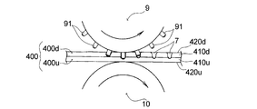
- the recessed part 7 which entered into the inside of the protruding part 40 from the non-raised surface side of the absorber 4 is formed by each convex part 91 of the convex roll 9.
- the continuous body 420d (lower layer core wrap sheet
- the core 41d is inserted into the upper absorbent core 41u from the surface far from the upper absorbent core 41u toward the surface closer to the upper absorbent core 41u.
- the lower layer absorbent body 4 d and the upper layer absorbent body 4 u are integrated and correspond to the respective concave sections 7 formed.
- a side recess 7o is formed.
- a continuous body 420d of a lower layer core wrap sheet 42d (a continuous body 420d1 of a first lower layer core wrap sheet 42d1, a continuous body 420d2 of a second lower layer core wrap sheet 42d2) and a wrapping body 410d of the lower layer absorbent core 41d.
- the continuous body 420u including only the upper layer core wrap sheet 42u of the upper layer absorbent body 4u is moved upward from the surface far from the upper layer absorbent core 41u of the lower layer absorbent core 41d. Toward side closer to the absorbent core 41 u, to get inside the recess 7.
- the tip portions of the convex portions 91 of the convex roll 9 used in the concave portion forming step protrude stepwise,
- the relationship between the width (W1) and the protrusion height (h) to the tip of the protrusion 910 is W1 ⁇ h. Therefore, since the pressure state at the tip of the convex portion is unlikely to change greatly, the core wrap sheet 42 is not easily broken, and the sanitary napkin 1 can be manufactured more stably and continuously.
- the method for manufacturing the sanitary napkin 1 includes the width (W1) of the tip of the protruding portion 910 and the distance between the outer peripheral edge located at the boundary between the protruding portion 910 and the protruding portion 910 of the protruding portion 91 ( The relationship with W2) is W1> W2. Therefore, as shown in FIG. 7, the continuous body 400 of the absorbent body 4 is compressed at two tip corners of the tip of the projection 91 and the tip of the projection 910 at the tip of each projection 91. Therefore, when the concave portion 7 is formed in the continuous body 400 of the absorbent body 4, the core wrap sheet 42 is hardly broken.
- the sanitary napkin 1 of the present embodiment after forming the recesses 7 in the absorbent body 4, the tip portions of the convex sections 91 of the convex rolls 9 are easily removed from the absorbent body 4, and Since the core wrap sheet 42 is difficult to wind around the tip portion of the portion 91, the sanitary napkin 1 can be manufactured stably and continuously.
- the continuous body of the absorbent body 4 manufactured as described above is cut to the length used for each sanitary napkin in the same manner as in the conventional longitudinal flow method, and the upper absorbent body 4u is then cut.
- the absorbent body 4 is interposed between the continuous body of the top sheet 2 and the continuous body of the back sheet 3, and after joining the top sheet and the back sheet outside the absorbent body 4, it is cut into a predetermined contour shape,
- the sanitary napkin 1 is manufactured.
- the continuous body of the surface sheet 2 before arranging the absorbent body 4 is used for forming a leak-proof cuff 6 in which elastic yarns 6c in an extended state are fixed to an overhanging portion 6b that is folded on each of both sides thereof.
- the continuous body of side sheets is overlapped and joined.
- the absorbent body 4 is arranged with the top sheet 2 and the back sheet 3
- an adhesive is applied to predetermined portions of the absorbent body 4, the top sheet 2, and the back sheet 3.
- the wing portion 5 is formed by bonding the wing forming sheet to each of both side portions of the continuous body of the top sheet 2 or the back sheet 3 before joining the absorber 4 or the top sheet 2.
- the back sheet 3 is formed by processing into the shape of the wing portion 5.
- the manufacturing method of the absorbent article of the present invention is not limited to the above-described embodiment, and can be changed as appropriate.
- each convex portion 91 used in the concave portion forming process has a tip portion 91b protruding one step, and the tip portion 91b has a protruding portion 910, but protrudes two or more steps. It may be.
- the tip 91b and the protrusion 910 of the protrusion 91 have a width between both side edges of the tip 91b of the protrusion 91 and the protrusion when the protrusion 91 is viewed from the side.
- the width between the side edges of the portion 910 is a tapered portion that gradually decreases toward the tip of the convex portion 91, it does not have to have a tapered portion.
- the outer peripheral edge located at the boundary with the protruding portion 910 at the interval (W2) is a portion of the outer diameter of the convex portion 91.
- the absorber 4 as shown in FIG. 2, a two-layer structure composed of the lower layer absorber 4d and the upper layer absorber 4u on the lower layer absorber 4d is used.
- the absorber 4 a one-layer structure may be used.
- the raised portion has a pulp basis weight that is greater than that of the surrounding portion, whereby the protruding portion is formed thicker than the surrounding portion.
- the core wrap sheet 42 is, as shown in FIG. 2, the first lower layer core wrap sheet 42d1 and the second lower layer core wrap sheet 42d2 of the lower layer core wrap sheet 42d that wraps the lower layer absorbent core 41d.
- the upper core wrap sheet 42u that wraps the upper absorbent core 41u is formed from three sheets, but it may be formed from two core wrap sheets. Specifically, when the absorbent core 41 is formed of only the lower layer absorbent core 41d, the first core wrap sheet and the lower layer absorbent core 41d covering the skin facing surface side of the lower layer absorbent core 41d.
- the manufacturing method of the absorbent article of this invention was formed with the lower layer absorbent body 4d and the upper layer absorbent body 4u which each coated the lower layer absorbent core 41d and the upper layer absorbent core 41u with one core wrap sheet.
- the absorber 4 may be used.
- the upper absorbent core 41u is arranged such that the upper absorbent core 41uc of the excretory part facing area C and the upper absorbent core 41ub of the rear area B are spaced apart in the vertical direction.
- the upper absorbent core 41u may be continuous without being separated.
- the sanitary napkin 1 is manufactured.
- the manufacturing method of the absorbent article of the present invention can also be used for other absorbents such as disposable diapers, incontinence pads, and liners. It is also suitable for manufacturing articles.
- a method for producing an absorbent article comprising an absorbent body in which an absorbent core is wrapped with a core wrap sheet,
- the absorber has a raised portion that is partially raised in the thickness direction,
- a continuous body of the absorbent body is supplied between a convex roll and a flat roll having a plurality of convex portions on the peripheral surface, and the concave portions that have entered the inside of the raised portion of the absorbent body by the convex portions.
- Each convex part used in the concave part forming step has a tip part projecting stepwise, and has a projecting part at the tip part.
- the absorbent body is formed such that a recessed portion row in which the recessed portions are arranged at intervals in the longitudinal direction extends in the longitudinal direction, and the recessed portion row is formed in a plurality of rows in the lateral direction.
- the plurality of rows of recesses are formed at positions symmetrical with respect to the longitudinal center line extending in the longitudinal direction of the absorbent article, and each recess forming one recess row and each forming the other recess row.
- ⁇ 3> The relationship between the width (W1) of the tip of the protrusion and the distance (W2) between the outer periphery located at the boundary between the protrusion and the protrusion of the protrusion is W1> W2.
- the convex portions of the convex roll form concave portions that enter from the non-raised surface side of the absorbent body to the inside of the raised portions by the convex portions.
- ⁇ 1> to ⁇ 3 > The manufacturing method of the absorbent article of any one of>.
- ⁇ 5> As the absorber, a two-layer structure composed of a lower layer absorber and an upper layer absorber on the lower layer absorber is used.
- the lower layer absorber and the upper layer absorber each have a lower layer absorbent core and an upper layer absorbent core,
- the continuum of the lower layer absorbent core has a surface side far from the upper layer absorbent core of the continuum of the lower layer absorbent core and is coated with a continuum of the second lower layer core wrap sheet.
- the portion of the first lower core wrap sheet continuous body that is coated with a continuous body of the first lower core wrap sheet on the surface side close to the upper absorbent core and extends laterally from the left and right sides of the lower absorbent core Each is folded to the surface side far from the upper absorbent core of the lower layer absorbent, and the folded tip portions are formed so as to cover the left and right sides of the continuous body of the second lower layer core wrap sheet.
- the continuum of the upper absorbent core has a surface side far from the lower absorbent core of the upper absorbent core continuum, and is covered with a continuum of the upper core wrap sheet.
- Each part of the continuous body of the upper layer core wrap sheet extending to the side is folded to the surface side of the upper layer absorbent core close to the lower layer absorbent core, and each of the folded tip portions is overlapped.
- the ratio (W1 / h) is preferably 1 or more, more preferably 2.5 or more, preferably 50 or less, more preferably 20 or less, specifically The method for producing an absorbent article according to any one of ⁇ 1> to ⁇ 7>, preferably 1 or more and 50 or less, and more preferably 2.5 or more and 20 or less.
- the ratio (W1 / W2) is preferably 1.1 or more, more preferably 2 or more, preferably 20 or less, more preferably 6 or less, Specifically, the method for producing an absorbent article according to any one of the above ⁇ 3> to ⁇ 8>, preferably 1.1 or more and 20 or less, and more preferably 2 or more and 6 or less.
- the width (W1) of the tip of the protrusion is preferably 1 mm or more, more preferably 1.5 mm or more, more preferably 10 mm or less, still more preferably 5 mm or less, and specifically 1 mm or more and 10 mm or less.
- the interval (W2) between the protruding portion and the outer peripheral edge located at the boundary between the protruding portions of the convex portion is preferably 0.1 mm or more, more preferably 0.2 mm or more, and preferably 10 mm or less, 3 mm or less is more preferable, specifically, it is preferably 0.1 mm or more and 10 mm or less, and more preferably 0.2 mm or more and 3 mm or less, according to any one of the above ⁇ 3> to ⁇ 10> Manufacturing method of absorbent article.
- the protrusion height (h) of the protrusion is preferably 0.1 mm or more, more preferably 0.2 mm or more, more preferably 3 mm or less, still more preferably 2 mm or less.
- ⁇ 13> The above-described ⁇ 1> to ⁇ 1>, wherein the width between both side edges of the tip portion of the convex portion is a tapered portion that gradually decreases toward the tip of the convex portion when the convex portion is viewed from the side.
- ⁇ 14> The above-described ⁇ 1> to ⁇ 13, wherein the convex portion has a tapered portion in which a width between both side edges of the protruding portion gradually decreases toward the tip of the convex portion when viewed from the side.
- the taper angle of the tip portion of the convex portion or the taper angle of the protrusion is preferably 10 ° or more, more preferably 20 ° or more, and preferably 150 ° or less, more preferably 90 ° or less. Is preferably 10 ° or more and 150 ° or less, and more preferably 20 ° or more and 90 ° or less.
- the continuum of the manufactured absorbent body is cut to have a length used for individual absorbent articles (such as sanitary napkins), and absorbed between the continuum of the top sheet and the continuum of the back sheet.
- ⁇ 17> The method for producing an absorbent article according to any one of ⁇ 1> to ⁇ 16>, wherein the absorbent article is a sanitary napkin, a disposable diaper, an incontinence pad, or a liner.
- An absorbent article including an absorbent body in which an absorbent core is wrapped with a core wrap sheet,
- the absorber has a raised portion that is partially raised in the thickness direction,
- the absorber has a plurality of the recesses that have entered the inside of the raised portion of the absorber,
- the core wrap sheet has a sheet that covers the non-skin facing side of the absorbent core, separate from the sheet that covers the skin facing side of the absorbent core, and covers the non-skin facing side.
- ⁇ 19> The overlapping portion of the sheet covering the skin facing surface side of the absorbent core and the sheet covering the non-skin facing surface side is disposed on the non-skin facing surface side of the absorbent body. 18>. ⁇ 20> When one of the plurality of recesses is viewed, the sheet covering the non-skin facing surface side is continuous from the wall surface of the recess to the bottom of the recess. 18> or the absorbent article as described in said ⁇ 19>.
- the absorber comprises a two-layer structure comprising a lower layer absorber and an upper layer absorber on the lower layer absorber, The lower layer absorber and the upper layer absorber each have a lower layer absorbent core and an upper layer absorbent core,
- the raised portions are formed at intervals in a longitudinal direction of the absorbent article.
- the absorbent article according to ⁇ 22> wherein the absorbent body includes a lower layer core wrap sheet that wraps the lower layer absorbent core and an upper layer core wrap sheet that wraps the upper layer absorbent core.
- the lower layer core wrap sheet includes a first lower layer core wrap sheet that covers the skin facing surface side of the lower layer absorbent core, and a second lower layer core wrap that covers the non-skin facing surface side of the lower layer absorbent core.
- the absorbent article according to ⁇ 24> further comprising a sheet.
- ⁇ 26> The absorbent article according to ⁇ 25>, wherein the sheet covering the non-skin facing surface side of the lower layer absorbent core is the second lower layer core wrap sheet.
- the distance (pitch) between the concave portions adjacent to each other in the longitudinal direction forming the concave row is preferably 4 mm or more, more preferably 5 mm or more, more preferably 50 mm or less, and still more preferably 20 mm or less.
- the interval between the recess rows adjacent in the lateral direction is preferably 4 mm or more, more preferably 5 mm or more, more preferably 50 mm or less, further preferably 20 mm or less, and specifically 4 mm or more and 50 mm or less.
- the concave portions forming the concave row are formed by compressing the upper layer absorber and the lower layer absorber in the thickness direction in a two-layer structure portion composed of the upper layer absorber and the lower layer absorber.
- the portion including the bottom of the concave portion is formed in a stepwise recess in the upper absorbent core, and has a relatively large diameter concave portion and an outer peripheral edge of the bottom portion of the large diameter concave portion.
- ⁇ 34> The absorbent article according to any one of ⁇ 18> to ⁇ 33>, wherein the absorbent article is a sanitary napkin, a disposable diaper, an incontinence pad, or a liner.
- Example 1 Using the pair of convex rolls and flat rolls shown in FIG. 3, a continuous body of the absorbent body of Example 1 of the sanitary napkin shown in FIGS.
- a lower layer absorbent core (basis weight 250 g / m 2 ) continuum 410 d is replaced with a first lower layer core wrap sheet continuum 420 d 1 (basis weight 16 g / m 2 tissue paper).
- a second lower layer core wrap sheet continuous body 420d2 tissue paper having a basis weight of 16 g / m 2
- an upper layer absorbent core 41uc (basis weight 400 g / m 2 )
- a continuous body 410u in which upper layer absorbent cores 41ub (basis weight 400 g / m 2 ) are alternately arranged in the conveying direction are wrapped with a continuous body 420u of upper layer core wrap sheet (tissue paper having a basis weight of 16 g / m 2 ).
- the upper layer absorber continuous body 400u was fixed with a hot-melt adhesive (coating amount 5 g / m 2 ).
- Each convex portion 91 of the convex roll has a tip portion projecting stepwise, the entire height is 5 mm, the diameter of the convex portion 91 is ⁇ 4 mm, and the convex portions 91, 91 adjacent in the circumferential direction are adjacent to each other.
- the distance (pitch) between them was 10 mm, and the distance (pitch) between the convex row 91L, 91L adjacent in the rotation axis direction was 10 mm. Further, each convex portion 91 will be described in detail.
- the width (W1) of the tip of the protruding portion 910 is ⁇ 2 mm, and the distance (W2) between the outer peripheral edge located at the boundary between the protruding portion 910 and the protruding portion 910 of the convex portion 91. ) was 0.65 mm, and the protrusion height (h) of the protrusion 910 was 0.5 mm. That is, the ratio relationship (W1 / h) was 4, and the ratio relationship (W1 / W2) was 3.3. Moreover, the area of the flat front-end
- the taper angle ⁇ of the tip 91b of the convex portion 91 was 40 °, and the taper angle ⁇ of the protruding portion 910 was 40 °.
- a continuous body of the absorbent body of Example 1 was manufactured by adjusting the distance between the tip of each convex portion 91 of the convex roll 9 and the peripheral surface of the flat roll 10 to 0.3 mm.
- Example 2 A continuous body of the absorbent body of Example 2 was manufactured in the same manner as in Example 1 except that the distance between the tip of each convex portion 91 of the convex roll 9 and the peripheral surface of the flat roll 10 was adjusted to 0.4 mm. .
- Example 3 A continuous body of the absorbent body of Example 3 was produced in the same manner as in Example 1 except that the distance between the tip of each convex portion 91 of the convex roll 9 and the peripheral surface of the flat roll 10 was adjusted to 0.5 mm. .
- Comparative Example 1 The continuous body 400 of the absorber 4 same as Example 1 was used as a raw material.
- Each convex part of the convex roll used in Comparative Example 1 is different from each convex part of the convex roll used in Example 1, and compared with a sanitary napkin using a normal pin emboss that does not protrude stepwise.
- the absorbent body of Example 1 was produced.
- the pin embossment of the convex roll has an overall height of 5 mm, the diameter of the convex portion 91 is 3 mm, the distance (pitch) between the pin embosses adjacent in the circumferential direction is 10 mm, and is adjacent in the rotation axis direction.
- the distance (pitch) between rows of matching pin embossments was 10 mm. Further, the width of the tip of the pin emboss was 2 mm, and the area of the flat tip of the pin emboss was 3.14 mm 2 .
- the distance between the tip of each pin emboss of the convex roll and the peripheral surface of the flat roll was adjusted to 0.3 mm, and an absorbent body of Comparative Example 1 was produced.
- Comparative Example 2 A continuous body of the absorbent body of Comparative Example 2 was produced in the same manner as Comparative Example 1, except that the distance between the tip of each pin embossment of the convex roll and the peripheral surface of the flat roll was adjusted to 0.4 mm.
- Comparative Example 3 A continuous body of the absorbent body of Comparative Example 3 was produced in the same manner as Comparative Example 1 except that the distance between the tip of each pin embossment of the convex roll and the peripheral surface of the flat roll was adjusted to 0.5 mm.
- the continuous body of the absorbent bodies of Examples 1 to 3 has a tear rate (%) of the core wrap sheet as compared with the continuous body of the absorbent bodies of Comparative Examples 1 to 3. It turned out to be low. Therefore, if a pair of convex rolls and flat rolls for producing a continuous body of the absorbent bodies of Examples 1 to 3 is used, the absorbent body can be stably produced, and further the absorbent article can be stably produced. Can be expected.
- the core wrap sheet is hardly broken when the concave portion is formed in the absorbent body by the convex portion of the convex roll. Therefore, according to the manufacturing method of an absorbent article of the present invention, it can be expected that the absorbent article is stably manufactured. Moreover, the absorbent article of the present invention makes it difficult for the absorbent body to be twisted when worn, and further improvement in fit to the body can be expected.
Abstract
This manufacturing method is a method for manufacturing an absorptive article which is provided with an absorption body (4) formed by wrapping an absorptive core (41) with a core wrapping sheet (42). The absorption body (4) has a raised section (40) which is partially raised in the thickness direction. This manufacturing method is provided with a recess forming step for supplying the continuous body (400) of the absorption body between a protrusion roller (9), which has protrusions (91) on the outer peripheral surface thereof, and a flat roller (10) to form, by means of the protrusions (91), recesses (7) entering the inside of the raised section (40) and to cause the core wrapping sheet (42) to enter the inside of the raised section (40). The protrusions (91) are configured in such a manner that the tip portion (91b) of each of the protrusions (91) protrudes stepwise and that the tip portion (91b) has a sticking-out section (910). The relationship between the width (W1) of the tip of the sticking-out section (910) and the height (h) of protrusion of the sticking-out section (910) to the tip thereof is set to W1 ≥h.
Description
本発明は、生理用ナプキン、失禁パッド等の吸収性物品の製造方法に関する。
The present invention relates to a method for producing absorbent articles such as sanitary napkins and incontinence pads.
身体へのフィット性を良好にする観点から、本出願人は、先に、横方向中央領域に層数の多い部分を有する吸収性層を備え、該層数の多い部分に着用形状を安定化させる圧縮部が押圧されて設けられている生理用ナプキンを提案した(特許文献1参照)。
From the viewpoint of improving the fit to the body, the applicant previously provided an absorbent layer having a large number of layers in the lateral central region, and stabilized the wearing shape in the large number of layers. The sanitary napkin which the compression part to be pressed was provided was proposed (refer patent document 1).
また、同様の観点から、本出願人は、先に、肌対向面側に上層吸収体、非肌対向面側に下層吸収体を有する吸収体を備え、該吸収体を平面視したときに、上層吸収体と下層吸収体とが厚み方向に圧縮されてなる圧縮点を規則的に配列した生理用ナプキンを提案した(特許文献2参照)。
Further, from the same viewpoint, the applicant first comprises an absorber having an upper layer absorber on the skin facing surface side and a lower layer absorber on the non-skin facing surface side, and when the absorber is viewed in plan view, The sanitary napkin which arranged regularly the compression point formed by compressing an upper layer absorber and a lower layer absorber in the thickness direction was proposed (refer to patent documents 2).
しかし、特許文献1,2に記載の生理用ナプキンにおいては、圧縮部又は圧縮点を押圧して形成する際に、吸収体を構成する吸収性コアを包むコアラップシートが破れてしまうことがあった。このようなコアラップシートの破れを防止できると、生理用ナプキンの製造時に、圧縮部又は圧縮点を形成するロールの凸部が吸収体から抜け易くなり、生理用ナプキンを安定的に製造することが期待できる。また、コアラップシートの破れが防止できると、吸収性コアとコアラップシートとからなる吸収体が更に一体化され、着用時に吸収体がヨレ難くなり、身体へのフィット性の更なる向上が期待できる。
However, in the sanitary napkin described in Patent Documents 1 and 2, when the compression part or the compression point is pressed and formed, the core wrap sheet that wraps the absorbent core constituting the absorbent body may be torn. It was. If the core wrap sheet can be prevented from being torn, the convex part of the roll forming the compression part or the compression point can be easily removed from the absorbent body during the production of the sanitary napkin, and the sanitary napkin can be stably produced. Can be expected. In addition, if the core wrap sheet can be prevented from being torn, the absorbent body composed of the absorbent core and the core wrap sheet is further integrated, making the absorbent body difficult to twist when worn, and further improvement in fit to the body is expected. it can.
本発明は、ロールの凸部により押圧して、吸収体に圧縮部又は圧縮点等を形成する際に、コアラップシートに破れが生じ難い吸収性物品の製造方法に関する。
The present invention relates to a method for producing an absorbent article that is hard to be broken in a core wrap sheet when a compressed portion or a compression point is formed on an absorbent body by pressing with a convex portion of a roll.
本発明の吸収性物品の製造方法は、吸収性コアをコアラップシートで包んだ吸収体を備えた吸収性物品の製造方法であって、前記吸収体は、厚み方向に一部隆起した隆起部を有する。本発明の吸収性物品の製造方法は、前記吸収体の連続体を、周面に複数の凸部を有する凸ロールとフラットロールとの間に供給し、各前記凸部によって、前記吸収体の前記隆起部の内部にまで入り込んだ凹部を形成するとともに、前記コアラップシートを該隆起部の内部にまで入り込ませる凹部形成工程を備える。前記凹部形成工程に用いる各前記凸部は、その先端部分が段階的に突出して、該先端部分に突出部を有しており、該突出部の幅(W1)と該突出部の先端までの突出高さ(h)との関係を、W1≧hとする。
The manufacturing method of an absorbent article of the present invention is a manufacturing method of an absorbent article provided with an absorbent body in which an absorbent core is wrapped with a core wrap sheet, wherein the absorbent body is partly raised in the thickness direction. Have In the method for manufacturing an absorbent article according to the present invention, a continuous body of the absorbent body is supplied between a convex roll and a flat roll having a plurality of convex portions on a peripheral surface, and the convex portions of the absorbent body are supplied by the convex portions. While forming the recessed part which penetrated to the inside of the said protruding part, the recessed part formation process of making the said core wrap sheet | seat enter to the inside of this protruding part is provided. Each convex part used for the concave part forming step has a tip part projecting stepwise, and has a projecting part at the tip part. The width (W1) of the projecting part and the tip of the projecting part The relationship with the protrusion height (h) is W1 ≧ h.
また、本発明の吸収性物品は、吸収性コアをコアラップシートで包んだ吸収体を備えた吸収性物品であって、前記吸収体は、厚み方向に一部隆起した隆起部を有する。前記吸収体は、該吸収体の前記隆起部の内部にまで入り込んだ複数の前記凹部を有する。前記コアラップシートは、前記吸収性コアの肌対向面側を被覆するシートとは別体の、該吸収性コアの非肌対向面側を被覆するシートを有し、該非肌対向面側を被覆するシートが前記凹部において前記隆起部の内部にまで入り込んでいる。
Moreover, the absorbent article of the present invention is an absorbent article including an absorbent body in which an absorbent core is wrapped with a core wrap sheet, and the absorbent body has a raised portion that is partially raised in the thickness direction. The absorber has a plurality of the recesses that have entered the inside of the raised portion of the absorber. The core wrap sheet has a sheet that covers the non-skin facing side of the absorbent core, separate from the sheet that covers the skin facing side of the absorbent core, and covers the non-skin facing side. The sheet to be inserted penetrates into the raised portion in the concave portion.
以下、本発明の吸収性物品の製造方法及び本発明の吸収性物品を、その好ましい実施態様に基づき図面を参照しながら説明する。
先ず、本実施態様の製造方法により製造される生理用ナプキン及び本発明の吸収性物品である生理用ナプキンについて図1~図2を参照しながら説明する。
生理用ナプキン1は、図1に示すように、縦長の形状をしており、その着用時に着用者の排泄部に対向する部位である排泄部対向域Cと、排泄部対向域Cの前方へ延びる前方域Aと、排泄部対向域Cの後方へ延びる後方域Bとを有する。生理用ナプキン1は、その主たる構成部材として、図2に示すように、着用時に着用者の肌側に配される肌対向面側に位置する液透過性の表面シート2と、着用時に着用者の肌側とは反対側に配される非肌対向面側に位置する液不透過性又は液難透過性の裏面シート3とを有している。表面シート2と裏面シート3との間には液保持性の縦長の吸収体4が介在配置されている。 Hereinafter, the manufacturing method of the absorbent article of this invention and the absorbent article of this invention are demonstrated, referring drawings based on the preferable embodiment.
First, a sanitary napkin manufactured by the manufacturing method of this embodiment and a sanitary napkin which is an absorbent article of the present invention will be described with reference to FIGS.
As shown in FIG. 1, thesanitary napkin 1 has a vertically long shape. To the front of the excretory part facing area C, which is a part facing the excretion part of the wearer when worn, and the excretory part facing area C It has a front area A that extends and a rear area B that extends rearward of the excretory part facing area C. As shown in FIG. 2, the sanitary napkin 1 has a liquid-permeable surface sheet 2 located on the skin-facing surface side disposed on the skin side of the wearer when worn, and a wearer when worn, as shown in FIG. 2. A liquid-impermeable or liquid-impermeable back sheet 3 located on the non-skin facing surface side, which is disposed on the opposite side to the skin side. Between the top sheet 2 and the back sheet 3, a liquid-retaining vertically long absorbent body 4 is disposed.
先ず、本実施態様の製造方法により製造される生理用ナプキン及び本発明の吸収性物品である生理用ナプキンについて図1~図2を参照しながら説明する。
生理用ナプキン1は、図1に示すように、縦長の形状をしており、その着用時に着用者の排泄部に対向する部位である排泄部対向域Cと、排泄部対向域Cの前方へ延びる前方域Aと、排泄部対向域Cの後方へ延びる後方域Bとを有する。生理用ナプキン1は、その主たる構成部材として、図2に示すように、着用時に着用者の肌側に配される肌対向面側に位置する液透過性の表面シート2と、着用時に着用者の肌側とは反対側に配される非肌対向面側に位置する液不透過性又は液難透過性の裏面シート3とを有している。表面シート2と裏面シート3との間には液保持性の縦長の吸収体4が介在配置されている。 Hereinafter, the manufacturing method of the absorbent article of this invention and the absorbent article of this invention are demonstrated, referring drawings based on the preferable embodiment.
First, a sanitary napkin manufactured by the manufacturing method of this embodiment and a sanitary napkin which is an absorbent article of the present invention will be described with reference to FIGS.
As shown in FIG. 1, the
また、生理用ナプキン1は、図1に示すように、その排泄部対向域Cに、左右両側部から側方へ延出する一対のウイング部5,5を有している。ウイング部5は、裏面シート3及び/又は表面シート2の延長部分として形成されているか、又は裏面シート3及び表面シート2とは別部材から形成されている。裏面シート3及びウイング部5における非肌対向面には粘着剤層(図示せず)が設けられている。粘着剤層は、生理用ナプキン1を着用者のショーツへの取り付け状態において、生理用ナプキン1をショーツに固定するために用いられる。
Further, as shown in FIG. 1, the sanitary napkin 1 has a pair of wing portions 5 and 5 extending in the excretion portion facing area C from the left and right side portions to the side. The wing part 5 is formed as an extended portion of the back sheet 3 and / or the top sheet 2, or is formed from a member different from the back sheet 3 and the top sheet 2. An adhesive layer (not shown) is provided on the non-skin facing surface of the back sheet 3 and the wing part 5. The pressure-sensitive adhesive layer is used to fix the sanitary napkin 1 to the shorts when the sanitary napkin 1 is attached to the wearer's shorts.
また、生理用ナプキン1は、図1,図2に示すように、その表面シート2側における左右の両側部に、生理用ナプキン1の縦方向に延びる一対の防漏カフ6が設けられている。防漏カフ6は、生理用ナプキン1においては、図2に示すように、上方へ向けて起立する壁部6aと、壁部6aの上端から水平方向へ張り出す張り出し部6bとから構成されている。したがって防漏カフ6の横方向断面は、略T字状の形状となる。壁部6aの基部は吸収体4と裏面シート3との間に位置している。張り出し部6bは、その上面が略平面になっており、生理用ナプキン1の着用時に該張り出し部6bが着用者の肌に面でもって当接するようになっている。張り出し部6bには、防漏カフ6の延びる方向と同方向に延びる弾性糸6cが複数本配されている。弾性糸6cは、縦方向に伸長状態で張り出し部6bに固定されている。弾性糸6cはその収縮によって壁部6aを起立させるとともに、張り出し部6bの平面形状を安定化させて、張り出し部6bの肌への当接を確実なものとしている。
As shown in FIGS. 1 and 2, the sanitary napkin 1 is provided with a pair of leak-proof cuffs 6 extending in the vertical direction of the sanitary napkin 1 on the left and right side portions on the surface sheet 2 side. . In the sanitary napkin 1, as shown in FIG. 2, the leak-proof cuff 6 is composed of a wall portion 6a that stands upward and an overhanging portion 6b that projects horizontally from the upper end of the wall portion 6a. Yes. Accordingly, the transverse cross section of the leak-proof cuff 6 has a substantially T-shape. The base of the wall 6 a is located between the absorber 4 and the back sheet 3. The overhanging portion 6b has a substantially flat upper surface so that when the sanitary napkin 1 is worn, the overhanging portion 6b comes into contact with the skin of the wearer. A plurality of elastic yarns 6c extending in the same direction as the direction in which the leak-proof cuff 6 extends are arranged in the overhanging portion 6b. The elastic yarn 6c is fixed to the overhanging portion 6b in an elongated state in the vertical direction. The elastic yarn 6c erects the wall portion 6a by contraction thereof, stabilizes the planar shape of the overhang portion 6b, and ensures contact of the overhang portion 6b with the skin.
図1に示すように、張り出し部6bは、生理用ナプキン1の縦方向の前端及び後端の位置において、表面シート2と接合されている。また、張り出し部6bは、生理用ナプキン1の後端域Bにおいて、排泄部対向域Cとの境界部近傍の位置である中間固定部61においても表面シート2と接合されている。これらの接合によって、防漏カフ6はその起立が一層安定したものとなる。
As shown in FIG. 1, the overhanging portion 6 b is joined to the topsheet 2 at the position of the front end and the rear end in the vertical direction of the sanitary napkin 1. Further, the overhanging portion 6b is joined to the topsheet 2 also at the intermediate fixing portion 61 that is in the vicinity of the boundary portion with the excretory portion facing region C in the rear end region B of the sanitary napkin 1. By these joining, the leak-proof cuff 6 becomes more stable in standing.
生理用ナプキン1の備える吸収体4は、図1,図2に示すように、吸収性コア41をコアラップシート42で包んで形成されており、厚み方向に一部隆起した隆起部40を有する。吸収体4は、生理用ナプキン1においては、図1,図2に示すように、下層吸収体4dと下層吸収体4d上の上層吸収体4uとからなる2層構造のものとなっている。上層吸収体4uは、下層吸収体4dに比べて、その幅が小さく形成されており、上層吸収体4uは、下層吸収体4dの横方向中央域に重ねられている。上層吸収体4uと下層吸収体4dとは同じ長さで形成されている。吸収性コア41は、下層吸収体4dを構成する下層吸収性コア41dと、上層吸収体4uを構成する上層吸収性コア41uとを有する。生理用ナプキン1においては、隆起部40が上層吸収体4uの上層吸収性コア41uで形成されている。このように、生理用ナプキン1においては、厚み方向に一部隆起した厚み差のある吸収性コア41を用いて、隆起部40を有する吸収体4が形成されている。さらに具体的には、上層吸収体4uの上層吸収性コア41uは、生理用ナプキン1においては、排泄部対向域Cに配された排泄部対向域Cの上層吸収性コア41ucと、後方域Bの一部に配された後方域Bの上層吸収性コア41ubとを有している。生理用ナプキン1においては、吸収性コア41は、前方域Aから後方域Bに亘って配された下層吸収性コア41dの肌対向面側の横方向中央域に、排泄部対向域Cの上層吸収性コア41ucと後方域Bの上層吸収性コア41ubとが縦方向に間隔を空けて配されており、生理用ナプキン1の縦方向に離間して厚み差のある吸収性コア41を形成している。即ち、隆起部40は、生理用ナプキン1の縦方向に間隔を空けて形成されている。尚、吸収性コア41を平面視した場合、下層吸収性コア41dの輪郭が吸収性コア41の輪郭を画成している。
As shown in FIGS. 1 and 2, the absorbent body 4 included in the sanitary napkin 1 is formed by wrapping an absorbent core 41 with a core wrap sheet 42, and has a raised portion 40 that is partially raised in the thickness direction. . In the sanitary napkin 1, the absorbent body 4 has a two-layer structure including a lower layer absorbent body 4d and an upper layer absorbent body 4u on the lower layer absorbent body 4d, as shown in FIGS. The upper-layer absorber 4u is formed to have a smaller width than the lower-layer absorber 4d, and the upper-layer absorber 4u is overlapped with the lateral central region of the lower-layer absorber 4d. The upper layer absorber 4u and the lower layer absorber 4d are formed with the same length. The absorbent core 41 includes a lower layer absorbent core 41d constituting the lower layer absorber 4d and an upper layer absorbent core 41u constituting the upper layer absorber 4u. In the sanitary napkin 1, the raised portion 40 is formed by the upper absorbent core 41u of the upper absorbent body 4u. Thus, in the sanitary napkin 1, the absorbent body 4 having the raised portion 40 is formed using the absorbent core 41 having a thickness difference partially raised in the thickness direction. More specifically, in the sanitary napkin 1, the upper absorbent core 41u of the upper absorbent body 4u includes the upper absorbent core 41uc of the excretory part opposing region C disposed in the excretory part opposing region C and the rear region B. And an upper absorbent core 41ub of the rear region B disposed in a part of the rear region B. In the sanitary napkin 1, the absorbent core 41 has an upper layer of the excretory part facing region C in the lateral central region on the skin facing surface side of the lower layer absorbent core 41d disposed from the front region A to the rear region B. The absorbent core 41uc and the upper layer absorbent core 41ub in the rear region B are spaced apart in the vertical direction, and the sanitary napkin 1 is spaced apart in the vertical direction to form an absorbent core 41 having a thickness difference. ing. That is, the raised portions 40 are formed at intervals in the longitudinal direction of the sanitary napkin 1. When the absorbent core 41 is viewed in plan, the contour of the lower absorbent core 41d defines the contour of the absorbent core 41.
コアラップシート42は、吸収性コア41の肌対向面側を被覆するシートとは別体の、該吸収性コア41の非肌対向面側を被覆するシートを有している。具体的に生理用ナプキン1においては、図2に示すように、下層吸収性コア41dを包む下層コアラップシート42dと、上層吸収性コア41uを包む上層コアラップシート42uとを有している。下層コアラップシート42dは、生理用ナプキン1においては、図2に示すように、下層吸収性コア41dの肌対向面側(上層吸収性コア41uに近い面側)を被覆する第1下層コアラップシート42d1と、下層吸収性コア41dの非肌対向面側(上層吸収性コア41uに遠い面側)を被覆する第2下層コアラップシート42d2とを有している。前記非肌対向面側を被覆するシートとは、生理用ナプキン1においては、第2下層コアラップシート42d2が該当する。第1下層コアラップシート42d1は、その横方向の長さが、下層吸収性コア41dの横方向の長さよりも長いものである。第1下層コアラップシート42d1は、図2に示すように、下層吸収性コア41dの肌対向面(上層吸収性コア41uに近い面)の全域を被覆し、下層吸収性コア41dの左右両側部から側方へ延出する部分それぞれが下層吸収性コア41dの非肌対向面側(上層吸収性コア41uに遠い面側)に折られて、その折られた先端部分それぞれが、下層吸収性コア41dの非肌対向面(上層吸収性コア41uに遠い面)を被覆する第2下層コアラップシート42d2の左右両側部を覆っており、第1下層コアラップシート42d1と第2下層コアラップシート42d2との重なり部分43が、吸収体4の非肌対向面側に配されている。該左右両側部の重なり部分43において、第1下層コアラップシート42d1と第2下層コアラップシート42d2とは接合されていない。このようにして、下層吸収性コア41dは、第1下層コアラップシート42d1と第2下層コアラップシート42d2とにより包まれている。下層吸収体4dは下層吸収性コア41dと、下層吸収性コア41dを包む下層コアラップシート42d(第1下層コアラップシート42d1及び第2下層コアラップシート42d2)とで形成されている。
The core wrap sheet 42 has a sheet that covers the non-skin facing surface side of the absorbent core 41, which is separate from the sheet that covers the skin facing surface side of the absorbent core 41. Specifically, as shown in FIG. 2, the sanitary napkin 1 has a lower layer core wrap sheet 42d that wraps the lower layer absorbent core 41d and an upper layer core wrap sheet 42u that wraps the upper layer absorbent core 41u. In the sanitary napkin 1, the lower layer core wrap sheet 42d is a first lower layer core wrap that covers the skin facing surface side of the lower layer absorbent core 41d (the surface side close to the upper layer absorbent core 41u) as shown in FIG. The sheet 42d1 and the second lower layer core wrap sheet 42d2 that covers the non-skin facing surface side (the surface side far from the upper layer absorbent core 41u) of the lower layer absorbent core 41d are provided. In the sanitary napkin 1, the sheet covering the non-skin facing surface side corresponds to the second lower layer core wrap sheet 42d2. The first lower layer core wrap sheet 42d1 is longer in the lateral direction than the lateral length of the lower layer absorbent core 41d. As shown in FIG. 2, the first lower layer core wrap sheet 42d1 covers the entire area of the skin facing surface of the lower layer absorbent core 41d (surface close to the upper layer absorbent core 41u), and both left and right side portions of the lower layer absorbent core 41d. Each of the portions extending from the side to the side is folded to the non-skin-opposing surface side of the lower layer absorbent core 41d (the surface side far from the upper layer absorbent core 41u), and each of the folded tip portions is the lower layer absorbent core The left and right sides of the second lower layer core wrap sheet 42d2 covering the non-skin facing surface of 41d (the surface far from the upper layer absorbent core 41u) are covered, and the first lower layer core wrap sheet 42d1 and the second lower layer core wrap sheet 42d2 are covered. Is disposed on the non-skin facing surface side of the absorbent body 4. The first lower layer core wrap sheet 42d1 and the second lower layer core wrap sheet 42d2 are not joined at the overlapping portions 43 on the left and right side portions. In this manner, the lower layer absorbent core 41d is wrapped by the first lower layer core wrap sheet 42d1 and the second lower layer core wrap sheet 42d2. The lower layer absorbent body 4d is formed of a lower layer absorbent core 41d and a lower layer core wrap sheet 42d (a first lower layer core wrap sheet 42d1 and a second lower layer core wrap sheet 42d2) that wraps the lower layer absorbent core 41d.
上層コアラップシート42uは、その横方向の長さが、上層吸収性コア41uの横方向の長さよりも長いものである。上層コアラップシート42uは、生理用ナプキン1においては、図2に示すように、上層吸収性コア41uの肌対向面(下層吸収性コア41dに遠い面)の全域を被覆し、上層吸収性コア41uの左右両側部から側方へ延出する部分それぞれが上層吸収性コア41uの非肌対向面側(下層吸収性コア41dに近い面側)に折られて、その折られた先端部分それぞれが、重なり合っている。このようにして、上層吸収性コア41uは、上層コアラップシート42uにより包まれている。上層吸収体4uは、上層吸収性コア41u(上層吸収性コア41uc及び上層吸収性コア41ub)と、それを包む上層コアラップシート42uにより形成されている。
The upper layer core wrap sheet 42u has a lateral length longer than the lateral length of the upper absorbent core 41u. In the sanitary napkin 1, the upper layer core wrap sheet 42u covers the entire skin-facing surface of the upper layer absorbent core 41u (the surface far from the lower layer absorbent core 41d) as shown in FIG. Each of the portions extending from the left and right side portions of 41u to the side is folded to the non-skin facing surface side (surface side close to the lower layer absorbent core 41d) of the upper layer absorbent core 41u, and the folded tip portions are respectively , Are overlapping. In this way, the upper absorbent core 41u is wrapped with the upper core wrap sheet 42u. The upper layer absorbent body 4u is formed of an upper layer absorbent core 41u (upper layer absorbent core 41uc and upper layer absorbent core 41ub) and an upper layer core wrap sheet 42u that wraps the upper layer absorbent core 41u.
上層コアラップシート42uにより包まれた上層吸収性コア41uと、第1下層コアラップシート42d1と第2下層コアラップシート42d2とにより包まれた下層吸収性コア41dとは、生理用ナプキン1においては、図2に示すように、ホットメルト型接着剤等の接着剤11により固定されている。詳述すると、生理用ナプキン1においては、上層コアラップシート42uと上層吸収性コア41uとの間は接着剤により固定されておらず、第1下層コアラップシート42d1及び第2下層コアラップシート42d2と下層吸収性コア41dとの間も接着剤により固定されておらず、第1下層コアラップシート42d1と第2下層コアラップシート42d2との重なり部分も接着剤により固定されていない。しかし、第1下層コアラップシート42d1と上層コアラップシート42uとの間に接着剤11が塗布されており、上層吸収体4uと下層吸収体4dとが固定されて、生理用ナプキン1の吸収体4が形成されている。また、吸収体4の肌対向面側は表面シート2と、非肌対向面側は裏面シート3と、それぞれ接着剤11により固定されている。
In the sanitary napkin 1, the upper absorbent core 41u wrapped by the upper core wrap sheet 42u and the lower absorbent core 41d wrapped by the first lower core wrap sheet 42d1 and the second lower core wrap sheet 42d2 As shown in FIG. 2, it is fixed by an adhesive 11 such as a hot-melt adhesive. Specifically, in the sanitary napkin 1, the upper layer core wrap sheet 42u and the upper layer absorbent core 41u are not fixed by an adhesive, and the first lower layer core wrap sheet 42d1 and the second lower layer core wrap sheet 42d2 are used. The lower absorbent core 41d is not fixed by an adhesive, and the overlapping portion between the first lower core wrap sheet 42d1 and the second lower core wrap sheet 42d2 is not fixed by the adhesive. However, the adhesive 11 is applied between the first lower-layer core wrap sheet 42d1 and the upper-layer core wrap sheet 42u, and the upper-layer absorbent body 4u and the lower-layer absorbent body 4d are fixed, and the absorbent body of the sanitary napkin 1 4 is formed. Moreover, the skin facing surface side of the absorbent body 4 is fixed with the top sheet 2, and the non-skin facing surface side is fixed with the back surface sheet 3 with the adhesive 11.
上層コアラップシート42uは、前方域Aおよび後方域Bにおける、上層吸収性コア41uc又は上層吸収性コア41ubが存在しないも部位にも延出しており、生理用ナプキン1の縦方向において、上層コアラップシート42uと下層コアラップシート42dとは同じ長さで形成されている。なお、上層吸収性コア41u及び上層吸収性コア41ubの存在しない部分においても、便宜的に上層吸収体4uと称する。
The upper layer core wrap sheet 42u extends in the front region A and the rear region B where the upper layer absorbent core 41uc or the upper layer absorbent core 41ub does not exist and extends in the longitudinal direction of the sanitary napkin 1 The wrap sheet 42u and the lower core wrap sheet 42d are formed with the same length. In addition, also in the part in which the upper layer absorbent core 41u and the upper layer absorbent core 41ub do not exist, it is called the upper layer absorbent body 4u for convenience.
上層吸収体4uの上層吸収性コア41uと下層吸収体4dの下層吸収性コア41dとは、同種の材料から構成されていてもよく、あるいは異種の材料から構成されていてもよい。上述したように、生理用ナプキン1の吸収体4は、下層吸収性コア41dを下層コアラップシート42d(第1下層コアラップシート42d1及び第2下層コアラップシート42d2)で包んだ下層吸収体4d上に、排泄部対向域Cの上層吸収性コア41uc及び後方域Bの上層吸収性コア41ubが縦方向に離間した上層吸収性コア41uを上層コアラップシート42uで包んだ上層吸収体4uを配設固定して形成されている。ここで、例えば、上層吸収体4uが配されていない下層吸収体4dのみから構成される単層構造部分の厚みは、液の十分な保持性、及び、着用者の身体へのフィット性の点から、310Pa荷重下で、2mm以上が好ましく、3mm以上が更に好ましく、また10mm以下が好ましく、7mm以下が更に好ましく、具体的には、2mm以上10mm以下が好ましく、3mm以上7mm以下であることが更に好ましい。そして、下層吸収体4d上に上層吸収体4uが配された2層構造部分の厚みは、排泄部対向域Cを着用者の身体にフィット性良く当接させられる点から、310Pa荷重下で、3mm以上が好ましく、5mm以上が更に好ましく、また、12mm以下が好ましく、10mm以下が更に好ましく、具体的には、3mm以上12mm以下であることが好ましく、5mm以上10mm以下であることが更に好ましい。
The upper absorbent core 41u of the upper absorbent body 4u and the lower absorbent core 41d of the lower absorbent body 4d may be made of the same material or different materials. As described above, the absorbent body 4 of the sanitary napkin 1 includes the lower layer absorbent body 4d in which the lower layer absorbent core 41d is wrapped with the lower layer core wrap sheet 42d (the first lower layer core wrap sheet 42d1 and the second lower layer core wrap sheet 42d2). The upper absorbent core 4u, in which the upper absorbent core 41u in which the upper absorbent core 41uc and the upper absorbent core 41ub in the rear region B are separated in the vertical direction is covered with the upper core wrap sheet 42u, is disposed on the excretory part facing region C. It is formed and fixed. Here, for example, the thickness of the single-layer structure portion composed only of the lower layer absorber 4d in which the upper layer absorber 4u is not disposed is sufficient for the liquid retention and fit to the wearer's body. Therefore, under a load of 310 Pa, 2 mm or more is preferable, 3 mm or more is more preferable, 10 mm or less is preferable, 7 mm or less is more preferable, specifically, 2 mm or more and 10 mm or less is preferable, and 3 mm or more and 7 mm or less is preferable. Further preferred. And, the thickness of the two-layer structure part in which the upper layer absorber 4u is arranged on the lower layer absorber 4d is from the point that the excretory part facing area C is brought into contact with the wearer's body with good fit, under a load of 310 Pa, 3 mm or more is preferable, 5 mm or more is more preferable, 12 mm or less is preferable, 10 mm or less is more preferable, specifically, 3 mm or more and 12 mm or less is preferable, and 5 mm or more and 10 mm or less is more preferable.
生理用ナプキン1の吸収性コア41は、排泄部対向域Cに配置された上層吸収性コア41ucによって、多量の排泄液(経血)を素早く吸収するとともに、隣接する下層吸収性コア41dに排泄液を移行させる機能を有する。また、後方域Bに配置された上層吸収性コア41ubによって、臀部からの漏れを防止できるとともに、上層吸収性コア41ucでは容量不足になるくらいの多量の排泄液(経血)があったときは、補助的に吸収する役目を有する。下層吸収性コア41dは、上層吸収性コア41uから伝えられた排泄液をその縦方向に液拡散させて、上層吸収性コア41uから肌への液戻りを防止する機能を有する。かかる観点から、後述する凹部7は、下層吸収性コア41dの非肌対向面側から、上層吸収性コア41uに向けて、上層吸収性コア41uの内部にまで至り、かつ上層吸収性コア41uを貫通しないよう形成することが液伝達の点から好ましい。
The absorbent core 41 of the sanitary napkin 1 quickly absorbs a large amount of excretion fluid (menstrual blood) and is excreted by the adjacent lower absorbent core 41d by the upper absorbent core 41uc disposed in the excretory part facing region C. Has the function of transferring liquid. Moreover, when the upper layer absorbent core 41ub disposed in the rear region B can prevent leakage from the buttocks, and when there is a large amount of excretory fluid (menstrual blood) that the upper layer absorbent core 41uc has a capacity shortage , Has the role of supplementary absorption. The lower layer absorbent core 41d has a function of preventing the return of fluid from the upper layer absorbent core 41u to the skin by diffusing the excretory fluid transmitted from the upper layer absorbent core 41u in the vertical direction. From this point of view, the concave portion 7 to be described later extends from the non-skin facing surface side of the lower layer absorbent core 41d to the upper layer absorbent core 41u, and reaches the inside of the upper layer absorbent core 41u. It is preferable from the point of liquid transmission to form so as not to penetrate.
また、図1に示すように、生理用ナプキン1には、排泄部対向域Cの上層吸収性コア41ucの左右両側部の外方に位置する下層吸収体4dの部分に、表面シート2側から裏面シート3側に向けて窪んだ防漏溝8cが縦方向に延びて形成されている。各防漏溝8cは、その一端が生理用ナプキン1の前方域Aまで延びて、該前方域Aに形成されている円弧状の防漏溝8aと滑らかに接続されている。防漏溝8aは、上層吸収性コア41ucの前端部の外方に位置する上層吸収体4u及び下層吸収体4dの部分に、横方向に延びて形成されている。また、各防漏溝8cの他端は、後方域Bの上層吸収性コア41ubの左右両側部の外方に位置する下層吸収体4dの部分に縦方向に延びて形成されている防漏溝8bの一端と滑らかに接続されている。各防漏溝8bの他端は、生理用ナプキン1の後端近傍に横方向に延びて形成されている円弧状の防漏溝8dと滑らかに接続されている。防漏溝8dは、生理用ナプキン1の後方域Bにおいて、上層吸収体4u及び下層吸収体4dの部分に、横方向に延びて形成されている。このように、生理用ナプキン1には、これらの防漏溝8a,8b,8c,8dからなる閉じた形状の溝が形成されており、吸収体4と表面シート2とが一体化している。防漏溝からなる閉じた形状の溝は上層吸収性コア41u(上層吸収性コア41uc,41ub)の周りに位置する部分に形成されている。また、生理用ナプキン1においては、図1に示すように、排泄部対向域Cの上層吸収性コア41ucと後方域Bの上層吸収性コア41ubとの間に位置する上層吸収体4u及び下層吸収体4dの部分に横方向に延びる円弧状の防漏溝8eが形成されており、上層吸収性コア41ubの後端部と防漏溝8dとの間に位置する上層吸収体4u及び下層吸収体4dの部分に横方向に延びる円弧状の防漏溝8fが形成されている。
Moreover, as shown in FIG. 1, the sanitary napkin 1 is provided on the portion of the lower layer absorbent body 4d located outside the left and right sides of the upper layer absorbent core 41uc of the excretory part facing region C from the top sheet 2 side. A leak-proof groove 8c that is recessed toward the back sheet 3 side extends in the vertical direction. One end of each leak-proof groove 8c extends to the front area A of the sanitary napkin 1, and is smoothly connected to the arc-shaped leak-proof groove 8a formed in the front area A. The leak-proof groove 8a is formed to extend in the lateral direction in the upper layer absorber 4u and the lower layer absorber 4d located outside the front end portion of the upper layer absorbent core 41uc. Moreover, the other end of each leak-proof groove 8c is formed in the lower layer absorbent body 4d located outside the left and right sides of the upper-layer absorbent core 41ub in the rear region B and extending vertically. It is smoothly connected to one end of 8b. The other end of each leak-proof groove 8b is smoothly connected to an arc-shaped leak-proof groove 8d that extends in the lateral direction near the rear end of the sanitary napkin 1. The leak-proof groove 8d is formed in the rear region B of the sanitary napkin 1 so as to extend in the lateral direction in the upper layer absorber 4u and the lower layer absorber 4d. As described above, the sanitary napkin 1 is formed with a groove having a closed shape composed of the leak- proof grooves 8a, 8b, 8c, and 8d, and the absorbent body 4 and the topsheet 2 are integrated. A closed groove formed of a leak-proof groove is formed in a portion located around the upper absorbent core 41u (upper absorbent cores 41uc, 41ub). Further, in the sanitary napkin 1, as shown in FIG. 1, the upper layer absorbent body 4u and the lower layer absorbent member positioned between the upper layer absorbent core 41uc of the excretory part facing region C and the upper layer absorbent core 41ub of the rear region B. An arc-shaped leak-proof groove 8e extending in the lateral direction is formed in the body 4d, and the upper-layer absorber 4u and the lower-layer absorber positioned between the rear end portion of the upper-layer absorbent core 41ub and the leak-proof groove 8d An arc-shaped leak-proof groove 8f extending in the lateral direction is formed in the portion 4d.
吸収体4は、図1,図2に示すように、吸収体4の隆起部40の内部にまで入り込んだ複数の凹部7を有している。具体的には、吸収体4(吸収性コア41)は、図1,図2に示すように、吸収体4(吸収性コア41)の非隆起面側から隆起部40の内部にまで入り込んだ複数の凹部7を有している。更に具体的には、上述したように、生理用ナプキン1においては、吸収体4は、下層吸収体4dと上層吸収体4uとからなる2層構造のものである。そして、隆起部40が上層吸収体4uの上層吸収性コア41uで形成されている。そのため、各凹部7は、2層構造の部分においては、図2に示すように、下層吸収体4dの非肌対向面側(上層吸収体4uに遠い面側)から下層吸収体4dの肌対向面側(上層吸収体4uに近い面側)に向けて隆起し、上層吸収体4uの中身である上層吸収性コア41uの内部にまで入り込んで形成されている。
As shown in FIGS. 1 and 2, the absorbent body 4 has a plurality of concave portions 7 that have entered the inside of the raised portion 40 of the absorbent body 4. Specifically, as shown in FIG. 1 and FIG. 2, the absorbent body 4 (absorbent core 41) enters the raised portion 40 from the non-raised surface side of the absorbent body 4 (absorbent core 41). A plurality of recesses 7 are provided. More specifically, as described above, in the sanitary napkin 1, the absorbent body 4 has a two-layer structure including the lower layer absorbent body 4d and the upper layer absorbent body 4u. The raised portion 40 is formed by the upper absorbent core 41u of the upper absorbent body 4u. Therefore, as shown in FIG. 2, each recess 7 has a two-layer structure portion that faces the skin of the lower layer absorber 4 d from the non-skin facing surface side of the lower layer absorber 4 d (the surface side far from the upper layer absorber 4 u). It bulges toward the surface side (surface side close to the upper layer absorber 4u) and is formed so as to penetrate into the upper layer absorbent core 41u which is the contents of the upper layer absorber 4u.
各凹部7は、その深さが、吸収体4(上層吸収体4u,下層吸収体4d)の2層構造部分の厚み(310Pa荷重下)の20%以上95%以下、特に50%以上95%以下であることが、吸収体4の確実な圧縮の点から好ましい。
The depth of each recess 7 is 20% or more and 95% or less, particularly 50% or more and 95% of the thickness (under 310 Pa load) of the two-layer structure portion of the absorber 4 (upper layer absorber 4u, lower layer absorber 4d). It is preferable from the point of the reliable compression of the absorber 4 that it is the following.
下層吸収体4dを通過し上層吸収体4uの上層吸収性コア41uの内部にまで入り込んだ各凹部7の底部7tを含む部分について詳述すると、図2に示すように、各凹部7の底部7tを含む部分は、生理用ナプキン1においては、上層吸収性コア41uの内部に段階的に凹んで形成されており、相対的に径の大きい大径凹部7bと、大径凹部7bの底部の外周縁よりも内側に配され大径凹部7bから更に上層吸収性コア41uの内部に凹んだ相対的に径の小さい小径凹部7sとを有している。
The portion including the bottom portion 7t of each recess 7 that has passed through the lower layer absorber 4d and entered the upper absorbent core 41u of the upper layer absorber 4u will be described in detail. As shown in FIG. In the sanitary napkin 1, the sanitary napkin 1 is formed so as to be recessed stepwise inside the upper absorbent core 41u, and has a large-diameter recess 7b having a relatively large diameter and an outer portion of the bottom of the large-diameter recess 7b. It has a small-diameter recess 7s having a relatively small diameter, which is disposed on the inner side of the periphery and is recessed from the large-diameter recess 7b into the upper absorbent core 41u.
上述したように、上層吸収性コア41uの内部にまで至った各凹部7は、上層吸収性コア41uを貫通しないように突出して形成されている。そして、吸収体4は、生理用ナプキン1においては、図2に示すように、複数の凹部7それぞれに対応する位置に、吸収体4の隆起面側から非隆起面側に向かって僅かに凹んだ表面側凹部7oを有している。即ち、生理用ナプキン1の表面側凹部7oは、上層吸収性コア41uが、その肌対向面(下層吸収性コア41dに遠い面)で且つ複数の凹部7それぞれに対応する位置において、上層吸収性コア41uの肌対向面(下層吸収性コア41dに遠い面)側から上層吸収性コア41uの非肌対向面(下層吸収性コア41dに近い面)側に凹んで形成されている。更に、表面側凹部7oは、上層吸収性コア41uの肌対向面を被覆する上層コアラップシート42uが、その肌対向面(下層吸収性コア41dに遠い面)で且つ複数の凹部7それぞれに対応する位置において、肌対向面(下層吸収性コア41dに遠い面)側から非肌対向面(下層吸収性コア41dに近い面)側に凹んで形成されている。
As described above, each recess 7 reaching the inside of the upper absorbent core 41u is formed to protrude so as not to penetrate the upper absorbent core 41u. In the sanitary napkin 1, the absorbent body 4 is slightly recessed from the raised surface side of the absorbent body 4 toward the non-raised surface side at positions corresponding to the plurality of recessed portions 7 as shown in FIG. 2. It has a front surface side recess 7o. That is, the upper side absorbent core 41u of the sanitary napkin 1 has an upper layer absorbent property at a position corresponding to each of the plurality of concave portions 7 on the skin facing surface (surface far from the lower layer absorbent core 41d). The core 41u is recessed from the skin facing surface (surface far from the lower absorbent core 41d) side to the non-skin facing surface (surface close to the lower absorbent core 41d) side of the upper absorbent core 41u. Further, the upper-side core wrap sheet 42u that covers the skin-facing surface of the upper-layer absorbent core 41u corresponds to the skin-facing surface (surface far from the lower-layer absorbent core 41d) and each of the plurality of recesses 7 In the position where it does, it is dented from the skin facing surface (surface far from the lower layer absorbent core 41d) side to the non-skin facing surface (surface near the lower layer absorbent core 41d) side.
コアラップシート42は、吸収性コア41の非肌対向面側を被覆するシートが凹部7において隆起部40の内部にまで入り込んでいる。具体的に生理用ナプキン1においては、複数の凹部7の内の1個の凹部7を視た場合に、少なくとも該1個の凹部7においては、コアラップシート42における、前記非肌対向面側を被覆するシートに該当する第2下層コアラップシート42d2が凹部7の壁面7wから凹部7の底部7tに亘って連続している。上述したように、生理用ナプキン1においては、コアラップシート42は、上層吸収性コア41uを包む上層コアラップシート42u、及び下層吸収性コア41dを包む下層コアラップシート42d(第1下層コアラップシート42d1,第2下層コアラップシート42d2)を有している。その為、複数の凹部7の内の1個の凹部7を視た場合に、図2に示すように、該1個の凹部7において、下層コアラップシート42dにおける第2下層コアラップシート42d2のみならず、上層コアラップシート42uも、下層吸収性コア41dの非肌対向面側(上層吸収性コア41uに遠い面側)から下層吸収性コア41dの肌対向面側(上層吸収性コア41uに近い面側)に向けて突出し、上層吸収性コア41uの内部にまで入り込んでおり、大径凹部7bと小径凹部7sとによって段階的に形成された凹部7の壁面7wから小径凹部7sの底部7tに亘って連続している。即ち、上層吸収性コア41uの内部にまで入り込んだコアラップシート42が破れずに、凹部7の壁面7wから凹部7の底部7tに亘って連続している。尚、図2には不図示であるが、各凹部7の底部7tを含む部分においては、上層吸収体4uの上層コアラップシート42uと、下層吸収体4dの下層コアラップシート42dとの間に、圧密化された下層吸収体4dの下層吸収性コア41dが存在している。
In the core wrap sheet 42, the sheet covering the non-skin facing surface side of the absorbent core 41 has entered the inside of the raised portion 40 in the recess 7. Specifically, in the sanitary napkin 1, when one of the plurality of recesses 7 is viewed, at least one of the recesses 7 includes the core wrap sheet 42 on the non-skin facing surface side. The second lower-layer core wrap sheet 42d2 corresponding to the sheet covering the surface is continuous from the wall surface 7w of the recess 7 to the bottom 7t of the recess 7. As described above, in the sanitary napkin 1, the core wrap sheet 42 includes the upper layer core wrap sheet 42u that wraps the upper layer absorbent core 41u and the lower layer core wrap sheet 42d that wraps the lower layer absorbent core 41d (first lower layer core wrap). Sheet 42d1, second lower layer core wrap sheet 42d2). Therefore, when one recess 7 among the plurality of recesses 7 is viewed, only the second lower core wrap sheet 42d2 in the lower core wrap sheet 42d is provided in the single recess 7 as shown in FIG. In addition, the upper layer core wrap sheet 42u is also formed from the non-skin facing surface side of the lower layer absorbent core 41d (surface side far from the upper layer absorbent core 41u) to the skin facing surface side of the lower layer absorbent core 41d (to the upper layer absorbent core 41u). The bottom surface 7t of the small diameter recess 7s from the wall surface 7w of the recess 7 formed stepwise by the large diameter recess 7b and the small diameter recess 7s. Is continuous. That is, the core wrap sheet 42 that has entered the inside of the upper absorbent core 41 u is not torn and continues from the wall surface 7 w of the recess 7 to the bottom 7 t of the recess 7. Although not shown in FIG. 2, in the portion including the bottom 7t of each recess 7, the upper core wrap sheet 42u of the upper absorber 4u and the lower core wrap sheet 42d of the lower absorber 4d are interposed. The lower absorbent core 41d of the consolidated lower absorbent body 4d is present.
吸収性コア41をコアラップシート42で包んで形成された吸収体4には、図1に示すように平面視して、上述した凹部7が縦方向に間隔を空けて配されてなる凹部列7Lが、縦方向に延びて形成されている。このような凹部列7Lが横方向に複数列形成されており、生理用ナプキン1においては、2列形成されている。各凹部列7Lについて詳述すると、凹部列7Lを形成する凹部7は、上層吸収体4uと下層吸収体4dとからなる2層構造の部分においては、上層吸収体4uと下層吸収体4dとが厚み方向に圧縮されて形成されている。一方、排泄部対向域Cの上層吸収体4uの上層吸収性コア41ucよりも前端側、排泄部対向域Cの上層吸収体4uの上層吸収性コア41ucと後方域Bの上層吸収性コア41ubとの間、後方域Bの上層吸収体4uの上層吸収性コア41ubよりも後端側においては、凹部列7Lを形成する凹部7は、吸収性コア41としては下層吸収体4dのみが厚み方向に圧縮されて形成されている。このように、複数の凹部7による凹部列7Lは、前方部Aから後方部Bに亘って直線状に形成されている。2列の凹部列7L,7Lは、生理用ナプキン1においては、生理用ナプキン1の縦方向に延びる縦中心線(図示せず)に対して対称な位置に形成されており、一方の凹部列7Lを形成する各凹部7の位置と、他方の凹部列7Lを形成する各凹部7の位置も、前記縦中心線(図示せず)に対して対称に配されている。尚、生理用ナプキン1においては、2列の凹部列7L,7Lは、前記縦中心線(図示せず)に対して対称な位置に形成されているが、対称な位置に形成されていなくてもよく、一方の凹部列7Lを形成する各凹部7の位置と、他方の凹部列7Lを形成する各凹部7の位置とが、前記縦中心線(図示せず)に対して対称に配されてなくてもよい。
In the absorbent body 4 formed by wrapping the absorbent core 41 with the core wrap sheet 42, the concave portion row in which the concave portions 7 described above are arranged at intervals in the vertical direction as shown in FIG. 1. 7L is formed extending in the vertical direction. A plurality of such recess rows 7L are formed in the horizontal direction, and in the sanitary napkin 1, two rows are formed. Describing each recess row 7L in detail, the recess 7 forming the recess row 7L is composed of an upper layer absorber 4u and a lower layer absorber 4d in a two-layer structure portion composed of an upper layer absorber 4u and a lower layer absorber 4d. It is formed by being compressed in the thickness direction. On the other hand, the upper layer absorbent core 41uc of the upper part absorbent body 4u of the excretion part facing area C, the upper layer absorbent core 41uc of the upper part absorbent body 4u of the excretion part facing area C, and the upper layer absorbent core 41ub of the rear part B On the rear end side of the upper absorbent core 41ub of the upper absorbent body 4u in the rear region B, the concave portions 7 forming the concave row 7L are formed such that only the lower absorbent body 4d is in the thickness direction as the absorbent core 41. Compressed and formed. In this way, the recess row 7L formed by the plurality of recesses 7 is formed linearly from the front portion A to the rear portion B. In the sanitary napkin 1, the two rows of recesses 7L and 7L are formed at positions symmetrical to a vertical center line (not shown) extending in the longitudinal direction of the sanitary napkin 1, and one recess row The position of each recess 7 that forms 7L and the position of each recess 7 that forms the other recess row 7L are also arranged symmetrically with respect to the vertical center line (not shown). In the sanitary napkin 1, the two recess rows 7L and 7L are formed at positions symmetrical with respect to the vertical center line (not shown), but are not formed at positions symmetrical. Alternatively, the position of each recess 7 that forms one recess row 7L and the position of each recess 7 that forms the other recess row 7L are arranged symmetrically with respect to the vertical center line (not shown). It does not have to be.
生理用ナプキン1に関し、図1に示すように、2本の凹部列7L,7Lのうちの一方の凹部列7Lにおいては、縦方向前後で隣り合う凹部7,7同士の距離(ピッチ)は同じになっている。他方の凹部列7Lにおいても、縦方向前後で隣り合う凹部7,7同士の距離(ピッチ)は同じになっている。尚、生理用ナプキン1においては、一方の凹部列7Lにおいて前後で隣り合う凹部7,7同士の距離(ピッチ)と、他方の凹部列7Lにおいて前後で隣り合う凹部7,7同士の距離(ピッチ)とは同じであるが、同じでなくてもよい。尚、凹部7,7同士の距離(ピッチ)とは、一方の凹部7の中心と他方の凹部7の中心との間の中心間距離を意味する。
With respect to the sanitary napkin 1, as shown in FIG. 1, in one of the two recess rows 7L, 7L, the distance (pitch) between the recesses 7, 7 adjacent in the longitudinal direction is the same. It has become. Also in the other recess row 7L, the distances (pitch) between the recesses 7 adjacent to each other in the longitudinal direction are the same. In the sanitary napkin 1, the distance (pitch) between the recesses 7 and 7 adjacent in the front and rear in one recess row 7L and the distance (pitch) between the recesses 7 and 7 adjacent in the front and rear in the other recess row 7L. ) Is the same as, but not necessarily. The distance (pitch) between the recesses 7 and 7 means a center-to-center distance between the center of one recess 7 and the center of the other recess 7.
凹部列7Lを形成する縦方向に隣り合う凹部7,7同士の距離(ピッチ)は、後述する凸ロール9の凸部列91Lを形成する周方向に隣り合う凸部91,91同士の距離(ピッチ)に対応しており、4mm以上が好ましく、5mm以上が更に好ましく、また50mm以下が好ましく、20mm以下が更に好ましく、具体的には4mm以上50mm以下であることが好ましく、5mm以上20mm以下であることが更に好ましい。
横方向に隣り合う2本の凹部列7L,7L同士の間隔は、後述する凸ロール9の回転軸方向に隣り合う凸部列91L,91L同士の距離(ピッチ)に対応しており、4mm以上が好ましく、5mm以上が更に好ましく、また50mm以下が好ましく、20mm以下が更に好ましく、具体的には4mm以上50mm以下であることが好ましく、5mm以上20mm以下であることが更に好ましい。 The distance (pitch) between the concave portions 7 and 7 adjacent to each other in the longitudinal direction forming the concave row 7L is the distance between the convex portions 91 and 91 adjacent to each other in the circumferential direction forming the convex row 91L of the convex roll 9 (described later). 4 mm or more, preferably 5 mm or more, more preferably 50 mm or less, further preferably 20 mm or less, specifically preferably 4 mm or more and 50 mm or less, and preferably 5 mm or more and 20 mm or less. More preferably it is.
The interval between the two concave rows 7L, 7L adjacent in the horizontal direction corresponds to the distance (pitch) between the convex rows 91L, 91L adjacent in the rotation axis direction of the convex roll 9 described later, and is 4 mm or more. Is preferably 5 mm or more, more preferably 50 mm or less, further preferably 20 mm or less, specifically 4 mm or more and 50 mm or less, and more preferably 5 mm or more and 20 mm or less.
横方向に隣り合う2本の凹部列7L,7L同士の間隔は、後述する凸ロール9の回転軸方向に隣り合う凸部列91L,91L同士の距離(ピッチ)に対応しており、4mm以上が好ましく、5mm以上が更に好ましく、また50mm以下が好ましく、20mm以下が更に好ましく、具体的には4mm以上50mm以下であることが好ましく、5mm以上20mm以下であることが更に好ましい。 The distance (pitch) between the
The interval between the two
凹部7における小径凹部7sの底部先端の径は、後述する凸ロール9の突出部910の先端の幅(W1)に対応しており、1mm以上が好ましく、1.5mm以上が更に好ましく、10mm以下が好ましく、5mm以下が更に好ましく、具体的には1mm以上10mm以下であることが好ましく、1.5mm以上5mm以下であることが更に好ましい。
凹部7における小径凹部7sと大径凹部7bとの間隔は、後述する凸ロール9の突出部910と、凸部91の突出部910との境界に位置する外周縁との間隔(W2)に対応しており、0.1mm以上が好ましく、0.2mm以上が更に好ましく、また、5mm以下が好ましく、3mm以下が更に好ましく、具体的には0.1mm以上5mm以下であることが好ましく、0.2mm以上3mm以下であることが更に好ましい。
凹部7における小径凹部7sの大径凹部7bからの突出高さは、後述する凸ロール9の突出部910の突出高さ(h)に対応しており、0.1mm以上が好ましく、0.2mm以上が更に好ましく、また、3mm以下が好ましく、2mm以下が更に好ましく、具体的には0.1mm以上3mm以下であることが好ましく、0.2mm以上2mm以下であることが更に好ましい。 The diameter of the bottom tip of the small-diameter recess 7s in the recess 7 corresponds to the width (W1) of the tip of the protrusion 910 of the convex roll 9 described later, preferably 1 mm or more, more preferably 1.5 mm or more, and 10 mm or less. Is preferably 5 mm or less, specifically 1 mm or more and 10 mm or less, more preferably 1.5 mm or more and 5 mm or less.
The interval between the small-diameter recess 7s and the large-diameter recess 7b in the recess 7 corresponds to the interval (W2) between the protrusion 910 of the convex roll 9 described later and the outer peripheral edge located at the boundary between the protrusion 910 of the protrusion 91. 0.1 mm or more, preferably 0.2 mm or more, more preferably 5 mm or less, further preferably 3 mm or less, specifically 0.1 mm or more and 5 mm or less. More preferably, it is 2 mm or more and 3 mm or less.
The protruding height of the small-diameterconcave portion 7s from the large-diameter concave portion 7b in the concave portion 7 corresponds to the protruding height (h) of the protruding portion 910 of the convex roll 9 described later, and is preferably 0.1 mm or more, and 0.2 mm. The above is more preferable, 3 mm or less is preferable, 2 mm or less is more preferable, specifically 0.1 mm or more and 3 mm or less is preferable, and 0.2 mm or more and 2 mm or less is more preferable.
凹部7における小径凹部7sと大径凹部7bとの間隔は、後述する凸ロール9の突出部910と、凸部91の突出部910との境界に位置する外周縁との間隔(W2)に対応しており、0.1mm以上が好ましく、0.2mm以上が更に好ましく、また、5mm以下が好ましく、3mm以下が更に好ましく、具体的には0.1mm以上5mm以下であることが好ましく、0.2mm以上3mm以下であることが更に好ましい。
凹部7における小径凹部7sの大径凹部7bからの突出高さは、後述する凸ロール9の突出部910の突出高さ(h)に対応しており、0.1mm以上が好ましく、0.2mm以上が更に好ましく、また、3mm以下が好ましく、2mm以下が更に好ましく、具体的には0.1mm以上3mm以下であることが好ましく、0.2mm以上2mm以下であることが更に好ましい。 The diameter of the bottom tip of the small-
The interval between the small-
The protruding height of the small-diameter
本実施形態の生理用ナプキン1の形成材料について説明する。
表面シート2及び裏面シート3としては、それぞれ、通常、生理用ナプキン等の吸収性物品に用いられるものであれば、特に制限なく用いることができる。例えば、表面シート2としては、液透過性の不織布、開孔を有する樹脂フィルム等を用いることができ、裏面シート3としては、液不透過性又は撥水性の樹脂フィルム単体、該樹脂フィルムに不織布を重ねた積層体等を用いることができる。吸収体4の吸収性コア41としては、パルプ等の繊維材料や吸収性ポリマーの粒子から構成されたもの等を用いることができ、コアラップシート42としては、ティッシュペーパ又は透水性の不織布等を用いることができる。 A material for forming thesanitary napkin 1 of the present embodiment will be described.
As thetop sheet 2 and the back sheet 3, any one can be used without particular limitation as long as it is usually used for absorbent articles such as sanitary napkins. For example, a liquid-permeable nonwoven fabric, a resin film having an opening, or the like can be used as the top sheet 2, and a liquid-impermeable or water-repellent resin film alone or a nonwoven fabric on the resin film can be used as the back sheet 3. It is possible to use a laminated body or the like on which are stacked. The absorbent core 41 of the absorbent body 4 can be made of fiber material such as pulp or absorbent polymer particles, and the core wrap sheet 42 is made of tissue paper or water-permeable nonwoven fabric. Can be used.
表面シート2及び裏面シート3としては、それぞれ、通常、生理用ナプキン等の吸収性物品に用いられるものであれば、特に制限なく用いることができる。例えば、表面シート2としては、液透過性の不織布、開孔を有する樹脂フィルム等を用いることができ、裏面シート3としては、液不透過性又は撥水性の樹脂フィルム単体、該樹脂フィルムに不織布を重ねた積層体等を用いることができる。吸収体4の吸収性コア41としては、パルプ等の繊維材料や吸収性ポリマーの粒子から構成されたもの等を用いることができ、コアラップシート42としては、ティッシュペーパ又は透水性の不織布等を用いることができる。 A material for forming the
As the
ウイング部5を形成するシートとしては、それぞれ、通常、生理用ナプキン等の吸収性物品に用いられるものであれば、特に制限なく用いることができ、例えば裏面シート3と同様のものを用いることができる。防漏カフ6を形成するサイドシートとしては、それぞれ、通常、生理用ナプキン等の吸収性物品に用いられるものであれば、特に制限なく用いることができ、伸縮性のフィルム、不織布、織物またはそれらの積層シート等を用いることができる。防漏カフ6形成用の弾性糸6cとしては、天然ゴム、ポリウレタン、ポリスチレン-ポリイソプレン共重合体、ポリスチレン-ポリブタジエン共重合体、アクリル酸エチル-エチレン等のポリエチレン-αオレフィン共重合体等からなる糸状の伸縮性材料を用いることができる。
As the sheet for forming the wing portion 5, any sheet that is usually used for absorbent articles such as sanitary napkins can be used without particular limitation. For example, the same sheet as the back sheet 3 can be used. it can. As the side sheets for forming the leak-proof cuff 6, as long as they are usually used for absorbent articles such as sanitary napkins, they can be used without particular limitation, and can be used as stretchable films, nonwoven fabrics, woven fabrics or the like. A laminated sheet or the like can be used. The elastic yarn 6c for forming the leak-proof cuff 6 is made of natural rubber, polyurethane, polystyrene-polyisoprene copolymer, polystyrene-polybutadiene copolymer, polyethylene-α-olefin copolymer such as ethyl acrylate-ethylene, or the like. A thread-like stretchable material can be used.
表面シート2、裏面シート3又はウイング部5を形成するシートの固定には、通常、生理用ナプキン等の吸収性物品に用いられるホットメルト型接着剤等の接着剤、又はヒートエンボス、超音波エンボス、高周波エンボス等の融着手段が用いられる。
For fixing the sheet forming the top sheet 2, the back sheet 3 or the wing part 5, an adhesive such as a hot melt adhesive usually used for absorbent articles such as sanitary napkins, heat embossing, ultrasonic embossing, etc. A fusion means such as high-frequency embossing is used.
次に上述した本実施形態の生理用ナプキン1を使用した際の作用効果について説明する。
生理用ナプキン1は、図2に示すように、コアラップシート42が、吸収性コア41の肌対向面側を被覆する第1コアラップシート(第1下層コアラップシート42d1又は上層コアラップシート42u1)と非肌対向面側を被覆する第2コアラップシート(第2下層コアラップシート42d2)とを有しており、該第2コアラップシートが、凹部7において隆起部40の内部にまで入り込んでいる。即ち、生理用ナプキン1においては、下層コアラップシート42が、下層吸収性コア41dの肌対向面側を被覆する第1下層コアラップシート42d1と、非肌対向面側を被覆する第2下層コアラップシート42d2とを有し、第2下層コアラップシート42d2が、下層吸収性コア41dの非肌対向面側(上層吸収性コア41uに遠い面側)から下層吸収性コア41dの肌対向面側(上層吸収性コア41uに近い面側)に向けて突出し、上層吸収性コア41uの内部にまで入り込んでいる。このように、コアラップシート42が、吸収性コア41の肌対向面側を被覆する第1コアラップシートと非肌対向面側を被覆する第2コアラップシートとを有しているので、凸ロールの凸部を押し込む際に幅方向の張力が掛かり難いため、コアラップシート42が破れ難く、隆起部40の内部まで入り込む凹部7を形成し易い。特に、生理用ナプキン1においては、第1下層コアラップシート42d1と第2下層コアラップシート42d2との重なり部分43が接着剤により固定されておらず、分離しているので、凸ロールの凸部を押し込む際に張力が更にかかり難くなるためコアラップシート42が破れ難くなる。このような効果は、特に厚い吸収体4のときは有効である。 Next, the effect at the time of using thesanitary napkin 1 of this embodiment mentioned above is demonstrated.
As shown in FIG. 2, thesanitary napkin 1 includes a first core wrap sheet (first lower layer core wrap sheet 42 d 1 or upper layer core wrap sheet 42 u 1) in which the core wrap sheet 42 covers the skin facing surface side of the absorbent core 41. ) And a second core wrap sheet (second lower layer core wrap sheet 42d2) that covers the non-skin facing surface side, and the second core wrap sheet enters the inside of the raised portion 40 in the concave portion 7. It is out. That is, in the sanitary napkin 1, the lower layer core wrap sheet 42 includes the first lower layer core wrap sheet 42d1 that covers the skin facing surface side of the lower layer absorbent core 41d and the second lower layer core that covers the non-skin facing surface side. And the second lower layer core wrap sheet 42d2 is provided on the skin facing surface side of the lower absorbent core 41d from the non-skin facing surface side of the lower absorbent core 41d (the surface side far from the upper absorbent core 41u). It protrudes toward (the surface side close to the upper absorbent core 41u) and enters the upper absorbent core 41u. As described above, the core wrap sheet 42 includes the first core wrap sheet that covers the skin facing surface side of the absorbent core 41 and the second core wrap sheet that covers the non-skin facing surface side. Since the tension in the width direction is difficult to be applied when the convex portion of the roll is pushed in, the core wrap sheet 42 is difficult to break, and the concave portion 7 that enters the inside of the raised portion 40 is easily formed. In particular, in the sanitary napkin 1, since the overlapping portion 43 of the first lower layer core wrap sheet 42d1 and the second lower layer core wrap sheet 42d2 is not fixed by the adhesive and separated, the convex portion of the convex roll The core wrap sheet 42 is less likely to be torn because it becomes difficult to apply tension when pushing in. Such an effect is particularly effective when the absorbent body 4 is thick.
生理用ナプキン1は、図2に示すように、コアラップシート42が、吸収性コア41の肌対向面側を被覆する第1コアラップシート(第1下層コアラップシート42d1又は上層コアラップシート42u1)と非肌対向面側を被覆する第2コアラップシート(第2下層コアラップシート42d2)とを有しており、該第2コアラップシートが、凹部7において隆起部40の内部にまで入り込んでいる。即ち、生理用ナプキン1においては、下層コアラップシート42が、下層吸収性コア41dの肌対向面側を被覆する第1下層コアラップシート42d1と、非肌対向面側を被覆する第2下層コアラップシート42d2とを有し、第2下層コアラップシート42d2が、下層吸収性コア41dの非肌対向面側(上層吸収性コア41uに遠い面側)から下層吸収性コア41dの肌対向面側(上層吸収性コア41uに近い面側)に向けて突出し、上層吸収性コア41uの内部にまで入り込んでいる。このように、コアラップシート42が、吸収性コア41の肌対向面側を被覆する第1コアラップシートと非肌対向面側を被覆する第2コアラップシートとを有しているので、凸ロールの凸部を押し込む際に幅方向の張力が掛かり難いため、コアラップシート42が破れ難く、隆起部40の内部まで入り込む凹部7を形成し易い。特に、生理用ナプキン1においては、第1下層コアラップシート42d1と第2下層コアラップシート42d2との重なり部分43が接着剤により固定されておらず、分離しているので、凸ロールの凸部を押し込む際に張力が更にかかり難くなるためコアラップシート42が破れ難くなる。このような効果は、特に厚い吸収体4のときは有効である。 Next, the effect at the time of using the
As shown in FIG. 2, the
また、生理用ナプキン1は、図2に示すように、吸収体4が隆起部40(上層吸収性コア41u)の内部にまで入り込んだ複数の凹部7を有しているので、着用時に吸収性コア41の隆起部40(上層吸収性コア41u)が変形し難く、吸収体4がヨレ難くなり、身体へのフィット性が向上する。また、生理用ナプキン1は、図2に示すように、吸収体4のコアラップシート42が、凹部7において隆起部40(上層吸収性コア41u)の内部にまで入り込んでおり、1個の凹部7を視た場合に、コアラップシート42が凹部7の壁面7wから凹部7の底部7tに亘って連続している。その為、隆起部40(上層吸収性コア41u)から下層(下層吸収性コア41d)への多量の排泄液(経血)が素早く移行でき、着用時のドライ感が向上し、身体へのフィット性が向上する。特に、生理用ナプキン1は、図1及び図2に示すように、吸収体4が複数の凹部7を有しているので、上層吸収体4uと下層吸収体4dとがしっかりと密着し易く、更に凹部7の底部から凹部7の周囲に沿ってパルプ密度が高くなっている部分を伝って排泄液(経血)が移行でき、上層吸収体4uから下層吸収体4dへの排泄液(経血)の移行がスムーズになる。
Further, as shown in FIG. 2, the sanitary napkin 1 has a plurality of concave portions 7 in which the absorbent body 4 has entered the bulged portion 40 (upper absorbent core 41 u), so that it is absorbable when worn. The raised portion 40 (upper absorbent core 41u) of the core 41 is not easily deformed, the absorbent body 4 is difficult to twist, and the fit to the body is improved. In the sanitary napkin 1, as shown in FIG. 2, the core wrap sheet 42 of the absorbent body 4 penetrates into the raised portion 40 (upper absorbent core 41 u) in the recess 7, and one recess 7, the core wrap sheet 42 is continuous from the wall surface 7 w of the recess 7 to the bottom 7 t of the recess 7. Therefore, a large amount of excretion fluid (menstrual blood) from the raised portion 40 (upper layer absorbent core 41u) to the lower layer (lower layer absorbent core 41d) can be transferred quickly, and the dry feeling at the time of wearing is improved, and the body fits Improves. Particularly, in the sanitary napkin 1, as shown in FIG. 1 and FIG. 2, the absorbent body 4 has a plurality of recesses 7, so that the upper layer absorbent body 4 u and the lower layer absorbent body 4 d are easy to adhere firmly, Furthermore, excretion fluid (menstrual blood) can be transferred from the bottom of the concave portion 7 along the periphery of the concave portion 7 through the portion where the pulp density is high, and excretion fluid (menstrual blood) from the upper layer absorbent 4u to the lower layer absorber 4d. ) Transitions smoothly.
また、生理用ナプキン1は、図2に示すように、1個の凹部7を視た場合に、コアラップシート42が凹部7の壁面7wから凹部7の底部7tに亘って連続しており、破れていないので、吸収体4と裏面シート3とを固定する際に、裏面シート3に浮きが生じ難く、着用時に吸収体4がヨレ難くなり、身体へのフィット性が向上する。
Further, as shown in FIG. 2, the sanitary napkin 1 has a core wrap sheet 42 that extends from the wall surface 7w of the recess 7 to the bottom 7t of the recess 7 when one recess 7 is viewed, Since it is not torn, when the absorbent body 4 and the back sheet 3 are fixed, the back sheet 3 is unlikely to float, and the absorbent body 4 is difficult to twist when worn, and the fit to the body is improved.
また、生理用ナプキン1は、図2に示すように、上層吸収性コア41uの内部にまで入り込んだ各凹部7の底部7tを含む部分が、大径凹部7bと小径凹部7sとから段階的に形成されている。その為、エンボス部分7sの角部に急激な厚み差ができ難く、エンボス部分7sの厚みを維持できる。
Further, as shown in FIG. 2, the sanitary napkin 1 includes a step including a bottom 7t of each recess 7 that has entered the upper layer absorbent core 41u in a stepwise manner from a large diameter recess 7b and a small diameter recess 7s. Is formed. Therefore, it is difficult to make a sharp thickness difference at the corner of the embossed portion 7s, and the thickness of the embossed portion 7s can be maintained.
また、生理用ナプキン1は、図2に示すように、上層吸収性コア41uの肌対向面における複数の凹部7それぞれに対応する位置に、上層吸収性コア41uの肌対向面側から凹んだ表面側凹部7oを有している。その為、生理用ナプキン1の装着時に使用者が座った状態等により表面シート2に圧力(表面シート2の厚み方向に掛かる力)が掛かったときに吸収体4の表面側凹部7oが他の部分より圧縮が掛りにくく、液が入り易い状態になるとの効果を奏する。
Further, as shown in FIG. 2, the sanitary napkin 1 is a surface that is recessed from the skin facing surface side of the upper absorbent core 41u at a position corresponding to each of the plurality of recesses 7 on the skin facing surface of the upper absorbent core 41u. It has a side recess 7o. Therefore, when the surface sheet 2 is subjected to pressure (force applied in the thickness direction of the surface sheet 2) due to the user sitting or the like when the sanitary napkin 1 is mounted, the surface-side concave portion 7o of the absorbent body 4 becomes another The effect is that compression is less likely to occur than the portion, and the liquid can easily enter.
また、生理用ナプキン1は、図1に示すように、凹部7が縦方向に間隔を空けて配されてなる縦方向に延びる凹部列7Lが2列形成されている。その為、2列の凹部列7Lを起点として、2列の凹部列7Lよりも横方向外方に位置する部分が、防漏カフ6の弾性糸6cの収縮力により着用時に肌対向面側に折れ曲がり易く、2列の凹部列7Lの間の部分が身体へフィットし易くなり、排泄液(経血)の横漏れを防止することができる。
Further, as shown in FIG. 1, the sanitary napkin 1 is formed with two rows of recessed portions 7L extending in the longitudinal direction in which the recessed portions 7 are arranged at intervals in the longitudinal direction. Therefore, a portion located laterally outward from the two recess rows 7L starting from the two recess rows 7L is located on the skin facing surface side when worn by the contraction force of the elastic yarn 6c of the leak-proof cuff 6 It is easy to bend, and the portion between the two rows of recesses 7L can be easily fitted to the body, and side leakage of excretory fluid (menstrual blood) can be prevented.
次に、本発明の吸収性物品の製造方法の好ましい実施態様を、上述した生理用ナプキン1を製造する場合を例にとり図3~図7を参照しながら説明する。
図3は、本実施態様の生理用ナプキン1の製造方法に好適に用いられる一対の、凸ロール9及びフラットロール10を模式的に示したものである。 Next, a preferred embodiment of the method for producing an absorbent article of the present invention will be described with reference to FIGS. 3 to 7 by taking as an example the production of thesanitary napkin 1 described above.
FIG. 3 schematically shows a pair ofconvex rolls 9 and flat rolls 10 that are preferably used in the method for producing the sanitary napkin 1 of the present embodiment.
図3は、本実施態様の生理用ナプキン1の製造方法に好適に用いられる一対の、凸ロール9及びフラットロール10を模式的に示したものである。 Next, a preferred embodiment of the method for producing an absorbent article of the present invention will be described with reference to FIGS. 3 to 7 by taking as an example the production of the
FIG. 3 schematically shows a pair of
一対の凸ロール9及びフラットロール10は、図3に示すように、アルミニウム合金又は鉄鋼等の金属製の円筒形状のものである。凸ロール9は、その周面に複数の凸部91を有している。一対の凸ロール9及びフラットロール10は、回転軸に駆動手段(不図示)からの駆動力が伝達されることによって、矢印で示す方向に連動して回転するようになっている。凸ロール9の回転速度は、生理用ナプキン1の製造装置の備える制御部(不図示)により制御されている。
As shown in FIG. 3, the pair of convex rolls 9 and flat rolls 10 are of a cylindrical shape made of metal such as aluminum alloy or steel. The convex roll 9 has a plurality of convex portions 91 on its peripheral surface. The pair of convex rolls 9 and the flat roll 10 are configured to rotate in conjunction with a direction indicated by an arrow when a driving force from a driving means (not shown) is transmitted to the rotation shaft. The rotational speed of the convex roll 9 is controlled by a control unit (not shown) provided in the sanitary napkin 1 manufacturing apparatus.
凸ロール9においては、図3に示すように、複数の凸部91が凸ロール9の周方向に一定間隔を空けて凸部列91Lを形成しており、該凸部列91Lが凸ロール9の軸長方向に2列形成されている。凸部列91Lの本数は、製造される生理用ナプキン1の備える吸収体4に形成される凹部列7Lの本数と一致しており、凸部列91Lを形成する複数の凸部91の個数は、吸収体4に形成される凹部列7Lを形成する複数の凹部7の個数と一致している。
In the convex roll 9, as shown in FIG. 3, a plurality of convex portions 91 form a convex portion row 91 </ b> L at regular intervals in the circumferential direction of the convex roll 9, and the convex portion row 91 </ b> L is the convex roll 9. Two rows are formed in the axial length direction. The number of the convex part row | line | column 91L corresponds with the number of the recessed part row | line | column 7L formed in the absorber 4 with which the sanitary napkin 1 manufactured is manufactured, and the number of the some convex part 91 which forms the convex part row | line | column 91L is the number of convex parts row | line | column 91L. The number of the plurality of recesses 7 forming the recess array 7L formed in the absorber 4 is the same.
凸ロール9の各凸部91は、凸ロール9の周面から凸部91の先端までの高さが、2mm以上が好ましく、3mm以上が更に好ましく、また20mm以下が好ましく、10mm以下が更に好ましく、具体的には2mm以上20mm以下であることが好ましく、3mm以上10mm以下であることが更に好ましい。凸部列91Lを形成する周方向に隣り合う凸部91,91同士の距離(ピッチ)は、4mm以上が好ましく、5mm以上が更に好ましく、また50mm以下が好ましく、20mm以下が更に好ましく、具体的には4mm以上50mm以下であることが好ましく、5mm以上20mm以下であることが更に好ましい。回転軸方向に隣り合う凸部列91L,91L同士の距離(ピッチ)は、4mm以上が好ましく、5mm以上が更に好ましく、また50mm以下が好ましく、20mm以下が更に好ましく、具体的には4mm以上50mm以下であることが好ましく、5mm以上20mm以下であることが更に好ましい。
凸ロール9の各凸部91の先端とフラットロール10の周面との間隔は、0.01mm以上が好ましく、0.05mm以上が更に好ましく、また10mm以下が好ましく、2mm以下が更に好ましく、具体的には0.01mm以上10mm以下であることが好ましく、0.05mm以上2mm以下であることが更に好ましい。
尚、フラットロール10の直径は、例えば、生理用ナプキン1の長さが340mmの場合、50mm以上300mm以下であることが好ましい。 Eachconvex portion 91 of the convex roll 9 has a height from the peripheral surface of the convex roll 9 to the tip of the convex portion 91 of preferably 2 mm or more, more preferably 3 mm or more, and preferably 20 mm or less, more preferably 10 mm or less. Specifically, it is preferably 2 mm or more and 20 mm or less, more preferably 3 mm or more and 10 mm or less. The distance (pitch) between the convex portions 91 and 91 adjacent to each other in the circumferential direction forming the convex row 91L is preferably 4 mm or more, more preferably 5 mm or more, more preferably 50 mm or less, still more preferably 20 mm or less. Is preferably 4 mm or more and 50 mm or less, and more preferably 5 mm or more and 20 mm or less. The distance (pitch) between the protrusions 91L and 91L adjacent in the rotation axis direction is preferably 4 mm or more, more preferably 5 mm or more, more preferably 50 mm or less, still more preferably 20 mm or less, specifically 4 mm or more and 50 mm. Or less, more preferably 5 mm or more and 20 mm or less.
The distance between the tip of eachconvex portion 91 of the convex roll 9 and the peripheral surface of the flat roll 10 is preferably 0.01 mm or more, more preferably 0.05 mm or more, and preferably 10 mm or less, more preferably 2 mm or less. Specifically, it is preferably 0.01 mm or more and 10 mm or less, and more preferably 0.05 mm or more and 2 mm or less.
For example, when the length of thesanitary napkin 1 is 340 mm, the diameter of the flat roll 10 is preferably 50 mm or more and 300 mm or less.
凸ロール9の各凸部91の先端とフラットロール10の周面との間隔は、0.01mm以上が好ましく、0.05mm以上が更に好ましく、また10mm以下が好ましく、2mm以下が更に好ましく、具体的には0.01mm以上10mm以下であることが好ましく、0.05mm以上2mm以下であることが更に好ましい。
尚、フラットロール10の直径は、例えば、生理用ナプキン1の長さが340mmの場合、50mm以上300mm以下であることが好ましい。 Each
The distance between the tip of each
For example, when the length of the
前記凹部形成工程に用いる各凸部91は、その先端部分91bが段階的に突出して、該先端部分91bに突出部910を有している。突出部910は、凸部91の頂部を形成し、図4に示すように、その先端が平面である。なお、先端が平面とは、複数の凸部91の頂部が形成する曲面(凸ロールの周面と平行な曲面)と、同じ曲率を有する場合も平面に含まれる。
各凸部91は、突出部910の先端の幅(W1)と該突出部910の先端までの突出高さ(h)との関係が、W1≧hとなっている。具体的には、突出部91sの先端の幅(W1)と、突出部910の突出高さ(h)との比率関係(W1/h)は、押し込み時のコアラップシートの破れにくさの観点から、1以上であることが好ましく、2.5以上であることが更に好ましく、50以下であることが好ましく、20以下であることが更に好ましく、具体的には、1以上50以下であることが好ましく、2.5以上20以下であることが更に好ましい。 Eachconvex portion 91 used in the concave portion forming process has a tip portion 91b protruding in a stepwise manner, and has a protruding portion 910 at the tip portion 91b. The projecting portion 910 forms the top of the convex portion 91, and as shown in FIG. The term “tip is flat” includes a curved surface (curved surface parallel to the peripheral surface of the convex roll) formed by the tops of the plurality of convex portions 91 and the same curvature.
Eachprotrusion 91 has a relationship between the width (W1) of the tip of the protrusion 910 and the protrusion height (h) to the tip of the protrusion 910 such that W1 ≧ h. Specifically, the ratio relationship (W1 / h) between the width (W1) of the leading end of the protruding portion 91s and the protruding height (h) of the protruding portion 910 is a viewpoint that the core wrap sheet is not easily torn during pushing. Therefore, it is preferably 1 or more, more preferably 2.5 or more, preferably 50 or less, more preferably 20 or less, specifically 1 or more and 50 or less. Is more preferably 2.5 or more and 20 or less.
各凸部91は、突出部910の先端の幅(W1)と該突出部910の先端までの突出高さ(h)との関係が、W1≧hとなっている。具体的には、突出部91sの先端の幅(W1)と、突出部910の突出高さ(h)との比率関係(W1/h)は、押し込み時のコアラップシートの破れにくさの観点から、1以上であることが好ましく、2.5以上であることが更に好ましく、50以下であることが好ましく、20以下であることが更に好ましく、具体的には、1以上50以下であることが好ましく、2.5以上20以下であることが更に好ましい。 Each
Each
また、図4に示すように、突出部910の先端の幅(W1)と、突出部910と凸部91の突出部910との境界に位置する外周縁との間隔(W2)との関係は、W1>W2となっていることが好ましい。具体的には、突出部910の先端の幅(W1)と、突出部910と凸部91の突出部910との境界に位置する外周縁との間隔(W2)との比率関係(W1/W2)は、押し込み時のコアラップシートの破れ難さの観点から、1.1以上であることが好ましく、2以上であることが更に好ましく、また、20以下であることが好ましく、6以下であることが更に好ましく、具体的には、1.1以上20以下であることが好ましく、2以上6以下であることが更に好ましい。
ここで、「凸部91の突出部910との境界に位置する外周縁」とは、凸部91の高さ方向において、突出部910とそれより下方に位置する部分との境界部に位置する、凸部91の外周縁である。 Further, as shown in FIG. 4, the relationship between the width (W1) of the tip of theprotrusion 910 and the distance (W2) between the outer periphery located at the boundary between the protrusion 910 and the protrusion 910 of the protrusion 91 is , W1> W2. Specifically, the ratio (W1 / W2) between the width (W1) of the tip of the protrusion 910 and the distance (W2) between the outer periphery located at the boundary between the protrusion 910 and the protrusion 910 of the protrusion 91. ) Is preferably 1.1 or more, more preferably 2 or more, and preferably 20 or less, preferably 6 or less, from the viewpoint of the difficulty of tearing the core wrap sheet during pressing. More preferably, it is preferably 1.1 or more and 20 or less, more preferably 2 or more and 6 or less.
Here, “the outer peripheral edge located at the boundary of theprotrusion 91 with the protrusion 910” is located at the boundary between the protrusion 910 and a portion positioned below the protrusion 91 in the height direction of the protrusion 91. This is the outer peripheral edge of the convex portion 91.
ここで、「凸部91の突出部910との境界に位置する外周縁」とは、凸部91の高さ方向において、突出部910とそれより下方に位置する部分との境界部に位置する、凸部91の外周縁である。 Further, as shown in FIG. 4, the relationship between the width (W1) of the tip of the
Here, “the outer peripheral edge located at the boundary of the
突出部910の先端の幅(W1)は、1mm以上が好ましく、更に1.5mm以上が好ましく、また、10mm以下が好ましく、5mm以下が更に好ましく、具体的には、1mm以上10mm以下であることが好ましく、1.5mm以上5mm以下であることが更に好ましい。
突出部910と凸部91の突出部910との境界に位置する外周縁との間隔(W2)は、0.1mm以上が好ましく、更に0.2mm以上が好ましく、また、10mm以下が好ましく、3mm以下が更に好ましく、具体的には、0.1mm以上10mm以下であることが好ましく、0.2mm以上3mm以下であることが更に好ましい。
突出部910の突出高さ(h)は、0.1mm以上が好ましく、更に0.2mm以上が好ましく、また、3mm以下が好ましく、2mm以下が更に好ましく、具体的には、0.1mm以上3mm以下であることが好ましく、0.2mm以上2mm以下であることが更に好ましい。
尚、凸部91の根元での幅W3は、0.8mm以上が好ましく、更に2mm以上が好ましく、また、30mm以下が好ましく、8mm以下が更に好ましく、具体的には、0.8mm以上30mm以下であることが好ましく、2mm以上8mm以下であることが更に好ましい。 The width (W1) of the tip of the protrudingportion 910 is preferably 1 mm or more, more preferably 1.5 mm or more, more preferably 10 mm or less, still more preferably 5 mm or less, and specifically 1 mm or more and 10 mm or less. Is preferably 1.5 mm or more and 5 mm or less.
The interval (W2) between theprotrusion 910 and the outer peripheral edge located at the boundary between the protrusions 910 of the protrusion 91 is preferably 0.1 mm or more, more preferably 0.2 mm or more, and preferably 10 mm or less, 3 mm The following is more preferable, specifically, 0.1 mm or more and 10 mm or less is preferable, and 0.2 mm or more and 3 mm or less is more preferable.
The protrusion height (h) of theprotrusion 910 is preferably 0.1 mm or more, more preferably 0.2 mm or more, more preferably 3 mm or less, still more preferably 2 mm or less, and specifically 0.1 mm or more and 3 mm. Or less, more preferably 0.2 mm or more and 2 mm or less.
The width W3 at the base of theconvex portion 91 is preferably 0.8 mm or more, more preferably 2 mm or more, preferably 30 mm or less, more preferably 8 mm or less, specifically 0.8 mm or more and 30 mm or less. It is preferable that it is 2 mm or more and 8 mm or less.
突出部910と凸部91の突出部910との境界に位置する外周縁との間隔(W2)は、0.1mm以上が好ましく、更に0.2mm以上が好ましく、また、10mm以下が好ましく、3mm以下が更に好ましく、具体的には、0.1mm以上10mm以下であることが好ましく、0.2mm以上3mm以下であることが更に好ましい。
突出部910の突出高さ(h)は、0.1mm以上が好ましく、更に0.2mm以上が好ましく、また、3mm以下が好ましく、2mm以下が更に好ましく、具体的には、0.1mm以上3mm以下であることが好ましく、0.2mm以上2mm以下であることが更に好ましい。
尚、凸部91の根元での幅W3は、0.8mm以上が好ましく、更に2mm以上が好ましく、また、30mm以下が好ましく、8mm以下が更に好ましく、具体的には、0.8mm以上30mm以下であることが好ましく、2mm以上8mm以下であることが更に好ましい。 The width (W1) of the tip of the protruding
The interval (W2) between the
The protrusion height (h) of the
The width W3 at the base of the
生理用ナプキン1の製造装置においては、更に、図4に示すように、凸部91の先端部分91bは、各凸部91を側面視して、先端部分91bの両側縁どうしの間の幅が、凸部91の先端に向かって漸次減少するテーパー状の部分となっていることが好ましい。凸部91の先端部分91bのテーパー角度αは、10°以上が好ましく、更に20°以上が好ましく、また、150°以下が好ましく、90°以下が更に好ましく、具体的には、10°以上150°以下が好ましく、20°以上90°以下であることが更に好ましい。更にまた、図4に示すように、各凸部91を側面視して、突出部910の両側縁どうしの間の幅が、凸部91の先端に向かって漸次減少するテーパー状の部分となっていることが好ましい。突出部910のテーパー角度βは、10°以上が好ましく、更に20°以上が好ましく、また、150°以下が好ましく、90°以下が更に好ましく、具体的には、10°以上150°以下が好ましく、20°以上90°以下であることが更に好ましい。凸部91の先端部分91bにテーパー角度αを設け、突出部910にテーパー角度βを設けることによって、凹部7を形成する際にコアラップシート42が破れ難く、凹部7を形成した吸収体4から凸部91が離れ易く、生産性が向上する。なお、凸部91の先端縁部(突出部910の先端の外周縁及び凸部91の突出部910との境界に位置する外周縁)には、シート42の破れ防止の観点から、面取り加工が施されていることが好ましく、図4に示す生理用ナプキン1の製造装置においては、約0.1mmのR加工が施されている。
In the sanitary napkin 1 manufacturing apparatus, as shown in FIG. 4, the tip portion 91 b of the convex portion 91 has a width between both side edges of the tip portion 91 b as viewed from the side. It is preferable that the tapered portion gradually decreases toward the tip of the convex portion 91. The taper angle α of the tip 91b of the convex portion 91 is preferably 10 ° or more, more preferably 20 ° or more, more preferably 150 ° or less, still more preferably 90 ° or less, specifically 10 ° or more and 150. It is preferably not more than °, more preferably not less than 20 ° and not more than 90 °. Furthermore, as shown in FIG. 4, when each convex portion 91 is viewed from the side, the width between both side edges of the protruding portion 910 is a tapered portion that gradually decreases toward the tip of the convex portion 91. It is preferable. The taper angle β of the protrusion 910 is preferably 10 ° or more, more preferably 20 ° or more, more preferably 150 ° or less, still more preferably 90 ° or less, and specifically preferably 10 ° or more and 150 ° or less. More preferably, it is 20 ° or more and 90 ° or less. By providing a taper angle α at the tip end portion 91b of the convex portion 91 and a taper angle β at the protruding portion 910, the core wrap sheet 42 is not easily broken when the concave portion 7 is formed. The convex portion 91 is easily separated, and the productivity is improved. In addition, from the viewpoint of preventing the sheet 42 from being broken, chamfering processing is performed on the leading edge portion of the convex portion 91 (the outer circumferential edge located at the boundary between the distal end of the protruding portion 910 and the protruding portion 910 of the protruding portion 91). In the manufacturing apparatus for the sanitary napkin 1 shown in FIG. 4, R processing of about 0.1 mm is performed.
凸ロール9の各凸部91及び各凸部91の頂部先端の形状(凸部91の先端及び突出部910の形状)に特に制限はなく、例えば、円形、多角形、楕円形等が挙げられ、各凸部91における突出部910の平面な先端の面積は、0.78mm2以上80mm2以下であることが好ましく、1.77mm2以上20mm2以下であることが更に好ましい。尚、凸部91の頂部先端の平面形状が、多角形又は楕円形の場合、先端の幅(W1)又は間隔(W2)、あるいは凸部91の根元での幅(W3)は、最も狭い位置での値を意味する。
There are no particular limitations on the shape of each convex portion 91 of the convex roll 9 and the top end of each convex portion 91 (the shape of the distal end of the convex portion 91 and the protruding portion 910), and examples thereof include a circle, a polygon, and an ellipse. , the area of the planar tip of the protruding portion 910 of each protrusion 91 is preferably 0.78 mm 2 or more 80 mm 2 or less, and more preferably 1.77 mm 2 or more 20 mm 2 or less. When the planar shape of the top end of the convex portion 91 is a polygon or an ellipse, the width (W1) or interval (W2) of the leading end or the width (W3) at the root of the convex portion 91 is the narrowest position. Means the value at.
次に、上述した一対の凸ロール9及びフラットロール10を用いて生理用ナプキン1を製造する製造方法について説明する。
本実施態様の生理用ナプキン1の製造方法は、いわゆる縦流れ方式の生理用ナプキンの製造方法であり、吸収体4の連続体を、周面に複数の凸部91を有する凸ロール9とフラットロール10との間に供給し、各凸部91によって、吸収体4の隆起部40の内部にまで入り込んだ凹部7を形成するとともに、コアラップシート42を隆起部40の内部にまで入り込ませる凹部形成工程を備えている。以下、具体的に説明する。 Next, the manufacturing method which manufactures thesanitary napkin 1 using a pair of convex roll 9 and the flat roll 10 mentioned above is demonstrated.
The method for manufacturing thesanitary napkin 1 according to the present embodiment is a method for manufacturing a so-called longitudinal flow type sanitary napkin, in which a continuous body of the absorbent body 4 is flattened with a convex roll 9 having a plurality of convex portions 91 on its peripheral surface and a flat surface. A recess that is supplied between the roll 10 and that forms the recess 7 that enters the inside of the raised portion 40 of the absorbent body 4 by each of the convex portions 91 and that allows the core wrap sheet 42 to enter the inside of the raised portion 40. A forming step is provided. This will be specifically described below.
本実施態様の生理用ナプキン1の製造方法は、いわゆる縦流れ方式の生理用ナプキンの製造方法であり、吸収体4の連続体を、周面に複数の凸部91を有する凸ロール9とフラットロール10との間に供給し、各凸部91によって、吸収体4の隆起部40の内部にまで入り込んだ凹部7を形成するとともに、コアラップシート42を隆起部40の内部にまで入り込ませる凹部形成工程を備えている。以下、具体的に説明する。 Next, the manufacturing method which manufactures the
The method for manufacturing the
先ず、図3に示すように、吸収体4の連続体400を用意する。図3に示す吸収体4の連続体400は、下層吸収性コア41dの連続体410dを第1下層コアラップシート42d1の連続体420d1と第2下層コアラップシート42d2の連続体420d2とにより包んだ下層吸収体4dの連続体400d上に、2種類の上層吸収性コア41uc及び上層吸収性コア41ubを交互に搬送方向に間欠的に配した連続体410uを上層コアラップシート42uの連続体420uにより包んだ上層吸収体4uの連続体400uを、ホットメルト型接着剤等の接着剤11により固定して形成されたものである。下層吸収体4dの連続体400dは、図3に示すように、下層吸収性コア41dの連続体410dの上層吸収性コア41uに遠い面側が第2下層コアラップシート42d2の連続体420d2で被覆されており、下層吸収性コア41dの連続体410dの上層吸収性コア41uに近い面側が第1下層コアラップシート42d1の連続体420d1で被覆されており、下層吸収性コア41dの左右両側部から側方へ延出する第1下層コアラップシート42d1の連続体420d1の部分それぞれが下層吸収性コア41dの上層吸収性コア41uに遠い面側に折られて、その折られた先端部分それぞれが、第2下層コアラップシート42d2の連続体420d2の左右両側部を覆って形成されている。上層吸収体4uの連続体400uは、図3に示すように、上層吸収性コア41uの連続体410uの下層吸収性コア41dに遠い面側が上層コアラップシート42uの連続体420uで被覆されており、上層吸収性コア41uの左右両側部から側方へ延出する上層コアラップシート42uの連続体420uの部分それぞれが上層吸収性コア41uの下層吸収性コア41dに近い面側に折られて、その折られた先端部分それぞれが、重なり合って形成されている。
First, as shown in FIG. 3, a continuous body 400 of the absorber 4 is prepared. The continuum 400 of the absorbent body 4 shown in FIG. 3 wraps the continuum 410d of the lower layer absorbent core 41d with the continuum 420d1 of the first lower layer core wrap sheet 42d1 and the continuum 420d2 of the second lower layer core wrap sheet 42d2. On the continuum 400d of the lower layer absorbent body 4d, a continuum 410u in which two types of upper layer absorbent cores 41uc and upper layer absorbent cores 41ub are alternately arranged in the conveying direction is formed by a continuum 420u of upper layer core wrap sheet 42u. The continuous body 400u of the wrapped upper layer absorbent body 4u is formed by being fixed with an adhesive 11 such as a hot-melt adhesive. As shown in FIG. 3, the continuum 400d of the lower layer absorbent body 4d is coated with a continuum 420d2 of the second lower layer core wrap sheet 42d2 on the surface side far from the upper absorbent core 41u of the continuum 410d of the lower layer absorbent core 41d. The surface of the lower layer absorbent core 41d that is close to the upper layer absorbent core 41u is covered with the continuum 420d1 of the first lower layer core wrap sheet 42d1, and the side from the left and right sides of the lower layer absorbent core 41d. Each portion of the continuous body 420d1 of the first lower core wrap sheet 42d1 extending in the direction is folded to the surface side far from the upper absorbent core 41u of the lower absorbent core 41d, and each folded tip portion is The lower layer core wrap sheet 42d2 is formed so as to cover the left and right sides of the continuous body 420d2. As shown in FIG. 3, the continuum 400u of the upper layer absorbent body 4u is coated with a continuum 420u of the upper layer core wrap sheet 42u on the surface side far from the lower layer absorbent core 41d of the continuum 410u of the upper layer absorbent core 41u. In addition, each portion of the continuous body 420u of the upper layer core wrap sheet 42u extending from the left and right sides of the upper layer absorbent core 41u to the side is folded to the surface side of the upper layer absorbent core 41u close to the lower layer absorbent core 41d, The folded tip portions are formed to overlap each other.
上述のような吸収体4の連続体400を、図3に示すように、下層吸収体4dの連続体400dが凸ロール9側に配され、上層吸収体4uの連続体400uがフラットロール10側に配された状態で、凸ロール9とフラットロール10との間に供給する。そして凸ロール9の各凸部91によって、吸収体4の非隆起面側から、隆起部40の内部にまで入り込んだ凹部7を形成する。具体的には、図5,図6に示すように、下層吸収体4dの上層吸収体4uに遠い面側から上層吸収体4uに近い面側に向けて、上層吸収体4uの連続体400uと下層吸収体4dの連続体400dとを厚み方向に圧縮して、上層吸収性コア41uの内部にまで入り込んだ凹部7を形成する。
As shown in FIG. 3, the continuum 400 of the absorbent body 4 is arranged on the convex roll 9 side, and the continuum 400u of the upper layer absorbent body 4u is on the flat roll 10 side. In a state where it is arranged in between, the convex roll 9 and the flat roll 10 are supplied. And the recessed part 7 which entered into the inside of the protruding part 40 from the non-raised surface side of the absorber 4 is formed by each convex part 91 of the convex roll 9. Specifically, as shown in FIG. 5 and FIG. 6, a continuous body 400u of the upper absorber 4u from the surface far from the upper absorber 4u of the lower absorber 4d to the surface near the upper absorber 4u, The continuum 400d of the lower layer absorbent body 4d is compressed in the thickness direction to form the recess 7 that has entered the upper layer absorbent core 41u.
そして、凹部7を形成するとともに、図5,図6に示すように、凸ロール9の各凸部91によって、下層吸収性コア41dの連続体410dを包む下層コアラップシート42dの連続体420d(第1下層コアラップシート42d1の連続体420d1,第2下層コアラップシート42d2の連続体420d2)及び上層吸収性コア41uの連続体410uを包む上層コアラップシート42uの連続体420uを、下層吸収性コア41dの上層吸収性コア41uに遠い面側から上層吸収性コア41uに近い面側に向けて、上層吸収性コア41uの内部にまで入り込ませる。
And while forming the recessed part 7, as shown in FIG. 5, FIG. 6, the continuous body 420d (lower layer core wrap sheet | seat 42d wrapping the continuous body 410d of the lower layer absorptive core 41d by each convex part 91 of the convex roll 9 ( A continuous body 420u of the first lower layer core wrap sheet 42d1, a continuous body 420d2 of the second lower layer core wrap sheet 42d2) and a continuous body 420u of the upper layer core wrap sheet 42u that wraps the continuous body 410u of the upper layer absorbent core 41u. The core 41d is inserted into the upper absorbent core 41u from the surface far from the upper absorbent core 41u toward the surface closer to the upper absorbent core 41u.
また、吸収体4の連続体400に凸ロール9の各凸部91による凹部7を形成することによって、下層吸収体4dと上層吸収体4uが一体化され、形成された各凹部7に対応する位置であって、且つ上層吸収体4uの連続体400uにおける下層吸収体4dに遠い面に、上層吸収体4uの下層吸収体4dに遠い面側から下層吸収体4dに近い面側に凹んだ表面側凹部7oが形成されるようになる。
Further, by forming the recesses 7 by the respective convex portions 91 of the convex roll 9 in the continuous body 400 of the absorbent body 4, the lower layer absorbent body 4 d and the upper layer absorbent body 4 u are integrated and correspond to the respective concave sections 7 formed. The surface which is a position and is recessed on the surface far from the lower layer absorber 4d in the continuum 400u of the upper layer absorber 4u, and from the surface far from the lower layer absorber 4d of the upper layer absorber 4u to the surface near the lower layer absorber 4d. A side recess 7o is formed.
尚、上層吸収体4uの連続体400uにおける、上層吸収性コア41uc及び上層吸収性コア41ubの配されていない部分においては、凸ロール9の各凸部91によって、図5,図6に示すように、下層吸収体4dの上層吸収体4uに遠い面側から上層吸収体4uに近い面側に向けて、下層吸収体4dの下層吸収性コア41dのみを厚み方向に圧縮して、凹部7を形成するとともに、下層吸収性コア41dの連続体410dを包む下層コアラップシート42dの連続体420d(第1下層コアラップシート42d1の連続体420d1,第2下層コアラップシート42d2の連続体420d2)及び上層吸収体4uの上層コアラップシート42uのみの連続体420uを、下層吸収性コア41dの上層吸収性コア41uに遠い面側から上層吸収性コア41uに近い面側に向けて、凹部7の内部に入り込ませる。
In the continuum 400u of the upper layer absorbent body 4u, the portions where the upper layer absorbent core 41uc and the upper layer absorbent core 41ub are not arranged are shown in FIG. 5 and FIG. Further, only the lower layer absorbent core 41d of the lower layer absorber 4d is compressed in the thickness direction from the surface side far from the upper layer absorber 4u of the lower layer absorber 4d to the surface side closer to the upper layer absorber 4u, so that the recess 7 is formed. A continuous body 420d of a lower layer core wrap sheet 42d (a continuous body 420d1 of a first lower layer core wrap sheet 42d1, a continuous body 420d2 of a second lower layer core wrap sheet 42d2) and a wrapping body 410d of the lower layer absorbent core 41d. The continuous body 420u including only the upper layer core wrap sheet 42u of the upper layer absorbent body 4u is moved upward from the surface far from the upper layer absorbent core 41u of the lower layer absorbent core 41d. Toward side closer to the absorbent core 41 u, to get inside the recess 7.
本実施態様の生理用ナプキン1の製造方法は、図4に示すように、凹部形成工程に用いる凸ロール9の各凸部91の先端部分が段階的に突出しており、突出部910の先端の幅(W1)と突出部910の先端までの突出高さ(h)との関係がW1≧hとなっている。
その為、凸部の先端での加圧状態が大きな変化にはなりにくいため、コアラップシート42に破れが生じ難く、生理用ナプキン1を更に安定的に連続して製造することができる。 In the method for manufacturing thesanitary napkin 1 according to this embodiment, as shown in FIG. 4, the tip portions of the convex portions 91 of the convex roll 9 used in the concave portion forming step protrude stepwise, The relationship between the width (W1) and the protrusion height (h) to the tip of the protrusion 910 is W1 ≧ h.
Therefore, since the pressure state at the tip of the convex portion is unlikely to change greatly, thecore wrap sheet 42 is not easily broken, and the sanitary napkin 1 can be manufactured more stably and continuously.
その為、凸部の先端での加圧状態が大きな変化にはなりにくいため、コアラップシート42に破れが生じ難く、生理用ナプキン1を更に安定的に連続して製造することができる。 In the method for manufacturing the
Therefore, since the pressure state at the tip of the convex portion is unlikely to change greatly, the
また、本実施態様の生理用ナプキン1の製造方法は、突出部910の先端の幅(W1)と、突出部910と凸部91の突出部910との境界に位置する外周縁との間隔(W2)との関係がW1>W2となっている。その為、図7に示すように、各凸部91の先端部分において、吸収体4の連続体400を、凸部91の先端と突出部910の先端との2つの先端角部で圧縮するようになるので、吸収体4の連続体400に凹部7を形成する際に、コアラップシート42に破れが生じ難い。従って、本実施態様の生理用ナプキン1の製造方法によれば、吸収体4に凹部7を形成後、吸収体4から凸ロール9の各凸部91の先端部分が抜け易く、また、各凸部91の先端部分にコアラップシート42が巻き付き難いので、生理用ナプキン1を安定的に連続して製造することができる。
In addition, the method for manufacturing the sanitary napkin 1 according to this embodiment includes the width (W1) of the tip of the protruding portion 910 and the distance between the outer peripheral edge located at the boundary between the protruding portion 910 and the protruding portion 910 of the protruding portion 91 ( The relationship with W2) is W1> W2. Therefore, as shown in FIG. 7, the continuous body 400 of the absorbent body 4 is compressed at two tip corners of the tip of the projection 91 and the tip of the projection 910 at the tip of each projection 91. Therefore, when the concave portion 7 is formed in the continuous body 400 of the absorbent body 4, the core wrap sheet 42 is hardly broken. Therefore, according to the method for manufacturing the sanitary napkin 1 of the present embodiment, after forming the recesses 7 in the absorbent body 4, the tip portions of the convex sections 91 of the convex rolls 9 are easily removed from the absorbent body 4, and Since the core wrap sheet 42 is difficult to wind around the tip portion of the portion 91, the sanitary napkin 1 can be manufactured stably and continuously.
次いで、以下、従来の縦流れ方式の製造方法と同様に、上述のように製造された吸収体4の連続体を、個々の生理用ナプキンに用いられる長さとなるよう切断し、上層吸収体4uが表面シート2側となるよう表面シート2の連続体上に切断した吸収体4を配し、その上から下層吸収体4dが裏面シート3側となるよう裏面シート3の連続体を配し、表面シート2の連続体と裏面シート3の連続体の間に吸収体4が介在させて、吸収体4の外側で表面シートと裏面シートを接合した後、所定の輪郭形状に切断して、目的とする生理用ナプキン1を製造する。なお、吸収体4を配置する前の表面シート2の連続体には、その両側部それぞれに、折り畳まれてなる張り出し部6bに伸長状態の弾性糸6cが固定された防漏カフ6形成用のサイドシートの連続体を重ね合わせて接合しておく。また、吸収体4を表面シート2、裏面シート3と配する際には、吸収体4または表面シート2、裏面シート3の所定箇所には接着剤を塗布しておく。また、ウイング部5は、ウイング形成用シートを、吸収体4と合流する前の表面シート2の連続体または裏面シート3の連続体の両側部それぞれに接合して形成するか、あるいは表面シート2または裏面シート3をウイング部5の形状に加工して形成する。
Subsequently, the continuous body of the absorbent body 4 manufactured as described above is cut to the length used for each sanitary napkin in the same manner as in the conventional longitudinal flow method, and the upper absorbent body 4u is then cut. Dispose the cut absorbent body 4 on the continuous body of the topsheet 2 so that it is on the topsheet 2 side, and arrange the continuous body of the backsheet 3 so that the lower layer absorbent body 4d is on the backsheet 3 side from above, The absorbent body 4 is interposed between the continuous body of the top sheet 2 and the continuous body of the back sheet 3, and after joining the top sheet and the back sheet outside the absorbent body 4, it is cut into a predetermined contour shape, The sanitary napkin 1 is manufactured. In addition, the continuous body of the surface sheet 2 before arranging the absorbent body 4 is used for forming a leak-proof cuff 6 in which elastic yarns 6c in an extended state are fixed to an overhanging portion 6b that is folded on each of both sides thereof. The continuous body of side sheets is overlapped and joined. In addition, when the absorbent body 4 is arranged with the top sheet 2 and the back sheet 3, an adhesive is applied to predetermined portions of the absorbent body 4, the top sheet 2, and the back sheet 3. In addition, the wing portion 5 is formed by bonding the wing forming sheet to each of both side portions of the continuous body of the top sheet 2 or the back sheet 3 before joining the absorber 4 or the top sheet 2. Alternatively, the back sheet 3 is formed by processing into the shape of the wing portion 5.
本発明の吸収性物品の製造方法は、上述の実施態様に何ら制限されるものではなく、適宜変更可能である。
The manufacturing method of the absorbent article of the present invention is not limited to the above-described embodiment, and can be changed as appropriate.
例えば、上述した実施態様においては、前記凹部形成工程に用いる各凸部91は、その先端部分91bが1段階突出して、該先端部分91bに突出部910を有しているが、2段階以上突出していてもよい。
また、上述した実施態様においては、凸部91の先端部分91b及び突出部910は、各凸部91を側面視して、凸部91の先端部分91bの両側縁どうしの間の幅、及び突出部910の両側縁どうしの間の幅が、凸部91の先端に向かって漸次減少するテーパー状の部分となっていたが、テーパー状の部分を有していなくてもよい。その場合、間隔(W2)の突出部910との境界に位置する外周縁は、凸部91の外径の部分となる。 For example, in the above-described embodiment, eachconvex portion 91 used in the concave portion forming process has a tip portion 91b protruding one step, and the tip portion 91b has a protruding portion 910, but protrudes two or more steps. It may be.
In the above-described embodiment, thetip 91b and the protrusion 910 of the protrusion 91 have a width between both side edges of the tip 91b of the protrusion 91 and the protrusion when the protrusion 91 is viewed from the side. Although the width between the side edges of the portion 910 is a tapered portion that gradually decreases toward the tip of the convex portion 91, it does not have to have a tapered portion. In that case, the outer peripheral edge located at the boundary with the protruding portion 910 at the interval (W2) is a portion of the outer diameter of the convex portion 91.
また、上述した実施態様においては、凸部91の先端部分91b及び突出部910は、各凸部91を側面視して、凸部91の先端部分91bの両側縁どうしの間の幅、及び突出部910の両側縁どうしの間の幅が、凸部91の先端に向かって漸次減少するテーパー状の部分となっていたが、テーパー状の部分を有していなくてもよい。その場合、間隔(W2)の突出部910との境界に位置する外周縁は、凸部91の外径の部分となる。 For example, in the above-described embodiment, each
In the above-described embodiment, the
また、上述した実施態様においては、吸収体4として、図2に示すように、下層吸収体4dと下層吸収体4d上の上層吸収体4uとからなる2層構造のものを用いているが、吸収体4として、1層構造のものを用いてもよい。その場合、隆起部は、周囲部分よりパルプ坪量が多くなっており、それによって周囲部分より隆起部の厚みが厚く形成されている。
Further, in the above-described embodiment, as the absorber 4, as shown in FIG. 2, a two-layer structure composed of the lower layer absorber 4d and the upper layer absorber 4u on the lower layer absorber 4d is used. As the absorber 4, a one-layer structure may be used. In this case, the raised portion has a pulp basis weight that is greater than that of the surrounding portion, whereby the protruding portion is formed thicker than the surrounding portion.
また、上述した実施態様においては、コアラップシート42が、図2に示すように、下層吸収性コア41dを包む下層コアラップシート42dの第1下層コアラップシート42d1及び第2下層コアラップシート42d2、並びに上層吸収性コア41uを包む上層コアラップシート42uの3枚から形成されているが、2枚のコアラップシートから形成されていればよい。具体的には、吸収性コア41が下層吸収性コア41dのみから形成されている場合には、下層吸収性コア41dの肌対向面側を被覆する第1コアラップシートと下層吸収性コア41dの非肌対向面側を被覆する第2コアラップシート(吸収性コア41の前記非肌対向面側を被覆するシート)との2枚から形成されていればよい。また、吸収性コア41が下層吸収性コア41d及び上層吸収性コア41uの2層構造のものであっても、2層構造の吸収性コアの肌対向面側を被覆する第1コアラップシートと2層構造の吸収性コアの非肌対向面側を被覆する第2コアラップシート(吸収性コア41の前記非肌対向面側を被覆するシート)との2枚から形成されていればよい。
また、本発明の吸収性物品の製造方法は、下層吸収性コア41d及び上層吸収性コア41uがそれぞれ1枚のコアラップシートで被覆された下層吸収体4dと上層吸収体4uとで形成された吸収体4を用いてもよい。 Moreover, in the embodiment mentioned above, thecore wrap sheet 42 is, as shown in FIG. 2, the first lower layer core wrap sheet 42d1 and the second lower layer core wrap sheet 42d2 of the lower layer core wrap sheet 42d that wraps the lower layer absorbent core 41d. In addition, the upper core wrap sheet 42u that wraps the upper absorbent core 41u is formed from three sheets, but it may be formed from two core wrap sheets. Specifically, when the absorbent core 41 is formed of only the lower layer absorbent core 41d, the first core wrap sheet and the lower layer absorbent core 41d covering the skin facing surface side of the lower layer absorbent core 41d. What is necessary is just to be formed from 2 sheets with the 2nd core wrap sheet | seat (sheet | seat which coat | covers the said non-skin opposing surface side of the absorptive core 41) which coat | covers the non-skin opposing surface side. Further, even if the absorbent core 41 has a two-layer structure of a lower layer absorbent core 41d and an upper layer absorbent core 41u, the first core wrap sheet covering the skin facing surface side of the two-layer structured absorbent core; What is necessary is just to be formed from 2 sheets with the 2nd core wrap sheet | seat (sheet | seat which coat | covers the said non-skin opposing surface side of the absorptive core 41) which covers the non-skin opposing surface side of the absorbent core of a two-layer structure.
Moreover, the manufacturing method of the absorbent article of this invention was formed with the lower layerabsorbent body 4d and the upper layer absorbent body 4u which each coated the lower layer absorbent core 41d and the upper layer absorbent core 41u with one core wrap sheet. The absorber 4 may be used.
また、本発明の吸収性物品の製造方法は、下層吸収性コア41d及び上層吸収性コア41uがそれぞれ1枚のコアラップシートで被覆された下層吸収体4dと上層吸収体4uとで形成された吸収体4を用いてもよい。 Moreover, in the embodiment mentioned above, the
Moreover, the manufacturing method of the absorbent article of this invention was formed with the lower layer
また、上述した実施態様においては、上層吸収性コア41uは、排泄部対向域Cの上層吸収性コア41ucと後方域Bの上層吸収性コア41ubとが縦方向に間隔を空けて配されていたが、離間せずに連続した上層吸収性コア41uとしてもよい。
In the embodiment described above, the upper absorbent core 41u is arranged such that the upper absorbent core 41uc of the excretory part facing area C and the upper absorbent core 41ub of the rear area B are spaced apart in the vertical direction. However, the upper absorbent core 41u may be continuous without being separated.
また、上述した実施態様においては、生理用ナプキン1を製造しているが、本発明の吸収性物品の製造方法は、生理用ナプキン以外にも、使い捨ておむつ、失禁パッド、ライナーなどのその他吸収性物品の製造にも好適である。
Moreover, in the embodiment described above, the sanitary napkin 1 is manufactured. However, in addition to the sanitary napkin, the manufacturing method of the absorbent article of the present invention can also be used for other absorbents such as disposable diapers, incontinence pads, and liners. It is also suitable for manufacturing articles.
前述した本発明の実施態様に関し、更に以下の付記(吸収性物品の製造方法、吸収性物品)を開示する。
The following additional notes (a manufacturing method of an absorbent article, an absorbent article) are further disclosed regarding the embodiment of the present invention described above.
<1> 吸収性コアをコアラップシートで包んだ吸収体を備えた吸収性物品の製造方法であって、
前記吸収体は、厚み方向に一部隆起した隆起部を有し、
前記吸収体の連続体を、周面に複数の凸部を有する凸ロールとフラットロールとの間に供給し、前記各凸部によって、前記吸収体の前記隆起部の内部にまで入り込んだ凹部を形成するとともに、前記コアラップシートを該隆起部の内部にまで入り込ませる凹部形成工程を備え、
前記凹部形成工程に用いる前記各凸部は、その先端部分が段階的に突出して、該先端部分に突出部を有しており、該突出部の先端の幅(W1)と該突出部の先端までの突出高さ(h)との関係を、W1≧hとする吸収性物品の製造方法。 <1> A method for producing an absorbent article comprising an absorbent body in which an absorbent core is wrapped with a core wrap sheet,
The absorber has a raised portion that is partially raised in the thickness direction,
A continuous body of the absorbent body is supplied between a convex roll and a flat roll having a plurality of convex portions on the peripheral surface, and the concave portions that have entered the inside of the raised portion of the absorbent body by the convex portions. And forming a recess forming step for allowing the core wrap sheet to enter the inside of the raised portion,
Each convex part used in the concave part forming step has a tip part projecting stepwise, and has a projecting part at the tip part. The width (W1) of the tip of the projecting part and the tip of the projecting part The manufacturing method of the absorbent article which makes the relationship with the protrusion height (h) up to W1> = h.
<2> 前記吸収体は、前記凹部が縦方向に間隔を空けて配されてなる凹部列が、縦方向に延びて形成されており、該凹部列が横方向に複数列形成されており、
複数列の前記凹部列は、吸収性物品の縦方向に延びる縦中心線に対して対称な位置に形成されており、一方の凹部列を形成する各凹部と、他方の凹部列を形成する各凹部も、前記縦中心線に対して対称の位置に配されている、前記<1>に記載の吸収性物品の製造方法。
<3> 前記突出部の先端の幅(W1)と、該突出部と前記凸部の突出部との境界に位置する外周縁との間隔(W2)との関係を、W1>W2とする前記<1>又は<2>に記載の吸収性物品の製造方法。
<4> 前記凹部形成工程においては、前記凸ロールの各前記凸部によって、前記吸収体の非隆起面側から、前記隆起部の内部にまで入り込んだ凹部を形成する前記<1>~<3>の何れか1に記載の吸収性物品の製造方法。
<5> 前記吸収体として、下層吸収体と該下層吸収体上の上層吸収体とからなる2層構造のものを用い、
前記下層吸収体及び前記上層吸収体は、それぞれ、下層吸収性コア及び上層吸収性コアを有し、
前記隆起部が前記上層吸収体の前記上層吸収性コアである前記<1>~<4>の何れか1に記載の吸収性物品の製造方法。 <2> The absorbent body is formed such that a recessed portion row in which the recessed portions are arranged at intervals in the longitudinal direction extends in the longitudinal direction, and the recessed portion row is formed in a plurality of rows in the lateral direction.
The plurality of rows of recesses are formed at positions symmetrical with respect to the longitudinal center line extending in the longitudinal direction of the absorbent article, and each recess forming one recess row and each forming the other recess row The method for manufacturing an absorbent article according to <1>, wherein the recesses are also arranged at positions symmetrical with respect to the longitudinal center line.
<3> The relationship between the width (W1) of the tip of the protrusion and the distance (W2) between the outer periphery located at the boundary between the protrusion and the protrusion of the protrusion is W1> W2. The manufacturing method of the absorbent article as described in <1> or <2>.
<4> In the concave portion forming step, the convex portions of the convex roll form concave portions that enter from the non-raised surface side of the absorbent body to the inside of the raised portions by the convex portions. <1> to <3 > The manufacturing method of the absorbent article of any one of>.
<5> As the absorber, a two-layer structure composed of a lower layer absorber and an upper layer absorber on the lower layer absorber is used.
The lower layer absorber and the upper layer absorber each have a lower layer absorbent core and an upper layer absorbent core,
The method for producing an absorbent article according to any one of <1> to <4>, wherein the raised portion is the upper absorbent core of the upper absorbent body.
<6> 前記下層吸収体の連続体は、下層吸収性コアの連続体の上層吸収性コアに遠い面側が第2下層コアラップシートの連続体で被覆されており、下層吸収性コアの連続体の上層吸収性コアに近い面側が第1下層コアラップシートの連続体で被覆されており、下層吸収性コアの左右両側部から側方へ延出する第1下層コアラップシートの連続体の部分それぞれが下層吸収性の上層吸収性コアに遠い面側に折られて、その折られた先端部分それぞれが、第2下層コアラップシートの連続体の左右両側部を覆って形成されている前記<5>に記載の吸収性物品の製造方法。
<7> 前記上層吸収体の連続体は、上層吸収性コアの連続体の下層吸収性コアに遠い面側が上層コアラップシートの連続体で被覆されており、上層吸収性コアの左右両側部から側方へ延出する上層コアラップシートの連続体の部分それぞれが上層吸収性コアの下層吸収性コアに近い面側に折られて、その折られた先端部分それぞれが、重なり合って形成されている前記<5>又は<6>に記載の吸収性物品の製造方法。
<8> 前記比(W1/h)は、1以上であることが好ましく、2.5以上であることが更に好ましく、50以下であることが好ましく、20以下であることが更に好ましく、具体的には、1以上50以下であることが好ましく、2.5以上20以下であることが更に好ましい前記<1>~<7>の何れか1に記載の吸収性物品の製造方法。
<9> 前記比(W1/W2)は、1.1以上であることが好ましく、2以上であることが更に好ましく、また、20以下であることが好ましく、6以下であることが更に好ましく、具体的には、1.1以上20以下であることが好ましく、2以上6以下であることが更に好ましい前記<3>~<8>の何れか1に記載の吸収性物品の製造方法。
<10> 前記突出部の先端の幅(W1)は、1mm以上が好ましく、更に1.5mm以上が好ましく、また、10mm以下が好ましく、5mm以下が更に好ましく、具体的には、1mm以上10mm以下であることが好ましく、1.5mm以上5mm以下であることが更に好ましい前記<1>~<9>の何れか1に記載の吸収性物品の製造方法。
<11> 前記突出部と凸部の突出部との境界に位置する外周縁との間隔(W2)は、0.1mm以上が好ましく、更に0.2mm以上が好ましく、また、10mm以下が好ましく、3mm以下が更に好ましく、具体的には、0.1mm以上10mm以下であることが好ましく、0.2mm以上3mm以下であることが更に好ましい前記<3>~<10>の何れか1に記載の吸収性物品の製造方法。
<12> 前記突出部の突出高さ(h)は、0.1mm以上が好ましく、更に0.2mm以上が好ましく、また、3mm以下が好ましく、2mm以下が更に好ましく、具体的には、0.1mm以上3mm以下であることが好ましく、0.2mm以上2mm以下であることが更に好ましい前記<1>~<11>の何れか1に記載の吸収性物品の製造方法。
<13> 前記凸部を側面視して、凸部の先端部分の両側縁どうしの間の幅が、凸部の先端に向かって漸次減少するテーパー状の部分となっている前記<1>~前記<12>の何れか1に記載の吸収性物品の製造方法。
<14> 前記凸部を側面視して、突出部の両側縁どうしの間の幅が、凸部の先端に向かって漸次減少するテーパー状の部分となっている前記<1>~前記<13>の何れか1に記載の吸収性物品の製造方法。
<15> 前記凸部の先端部分のテーパー角度又は突出部のテーパー角度は、10°以上が好ましく、更に20°以上が好ましく、また、150°以下が好ましく、90°以下が更に好ましく、具体的には、10°以上150°以下が好ましく、20°以上90°以下であることが更に好ましい前記<13>又は<14>に記載の吸収性物品の製造方法。
<16> 前記製造された吸収体の連続体を、個々の吸収性物品(生理用ナプキン等)に用いられる長さとなるよう切断し、表面シートの連続体と裏面シートの連続体の間に吸収体を介在させて、吸収体の外側で表面シートと裏面シートを接合した後、所定の輪郭形状に切断する前記<1>~<15>の何れか1に記載の吸収性物品の製造方法。
<17> 前記吸収性物品は、生理用ナプキン、使い捨ておむつ、失禁パッド、又はライナーである前記<1>~<16>の何れか1に記載の吸収性物品の製造方法。 <6> The continuum of the lower layer absorbent core has a surface side far from the upper layer absorbent core of the continuum of the lower layer absorbent core and is coated with a continuum of the second lower layer core wrap sheet. The portion of the first lower core wrap sheet continuous body that is coated with a continuous body of the first lower core wrap sheet on the surface side close to the upper absorbent core and extends laterally from the left and right sides of the lower absorbent core Each is folded to the surface side far from the upper absorbent core of the lower layer absorbent, and the folded tip portions are formed so as to cover the left and right sides of the continuous body of the second lower layer core wrap sheet. The manufacturing method of the absorbent article as described in 5>.
<7> The continuum of the upper absorbent core has a surface side far from the lower absorbent core of the upper absorbent core continuum, and is covered with a continuum of the upper core wrap sheet. Each part of the continuous body of the upper layer core wrap sheet extending to the side is folded to the surface side of the upper layer absorbent core close to the lower layer absorbent core, and each of the folded tip portions is overlapped. The manufacturing method of the absorbent article as described in said <5> or <6>.
<8> The ratio (W1 / h) is preferably 1 or more, more preferably 2.5 or more, preferably 50 or less, more preferably 20 or less, specifically The method for producing an absorbent article according to any one of <1> to <7>, preferably 1 or more and 50 or less, and more preferably 2.5 or more and 20 or less.
<9> The ratio (W1 / W2) is preferably 1.1 or more, more preferably 2 or more, preferably 20 or less, more preferably 6 or less, Specifically, the method for producing an absorbent article according to any one of the above <3> to <8>, preferably 1.1 or more and 20 or less, and more preferably 2 or more and 6 or less.
<10> The width (W1) of the tip of the protrusion is preferably 1 mm or more, more preferably 1.5 mm or more, more preferably 10 mm or less, still more preferably 5 mm or less, and specifically 1 mm or more and 10 mm or less. The method for manufacturing an absorbent article according to any one of the above items <1> to <9>, preferably 1.5 mm or more and 5 mm or less.
<11> The interval (W2) between the protruding portion and the outer peripheral edge located at the boundary between the protruding portions of the convex portion is preferably 0.1 mm or more, more preferably 0.2 mm or more, and preferably 10 mm or less, 3 mm or less is more preferable, specifically, it is preferably 0.1 mm or more and 10 mm or less, and more preferably 0.2 mm or more and 3 mm or less, according to any one of the above <3> to <10> Manufacturing method of absorbent article.
<12> The protrusion height (h) of the protrusion is preferably 0.1 mm or more, more preferably 0.2 mm or more, more preferably 3 mm or less, still more preferably 2 mm or less. The method for producing an absorbent article according to any one of the above items <1> to <11>, preferably 1 mm or more and 3 mm or less, and more preferably 0.2 mm or more and 2 mm or less.
<13> The above-described <1> to <1>, wherein the width between both side edges of the tip portion of the convex portion is a tapered portion that gradually decreases toward the tip of the convex portion when the convex portion is viewed from the side. The method for producing an absorbent article according to any one of <12>.
<14> The above-described <1> to <13, wherein the convex portion has a tapered portion in which a width between both side edges of the protruding portion gradually decreases toward the tip of the convex portion when viewed from the side. > The manufacturing method of the absorbent article of any one of>.
<15> The taper angle of the tip portion of the convex portion or the taper angle of the protrusion is preferably 10 ° or more, more preferably 20 ° or more, and preferably 150 ° or less, more preferably 90 ° or less. Is preferably 10 ° or more and 150 ° or less, and more preferably 20 ° or more and 90 ° or less. The method for producing an absorbent article according to <13> or <14>.
<16> The continuum of the manufactured absorbent body is cut to have a length used for individual absorbent articles (such as sanitary napkins), and absorbed between the continuum of the top sheet and the continuum of the back sheet. The method for producing an absorbent article according to any one of <1> to <15>, wherein the body sheet is interposed and the top sheet and the back sheet are joined outside the absorbent body, and then cut into a predetermined contour shape.
<17> The method for producing an absorbent article according to any one of <1> to <16>, wherein the absorbent article is a sanitary napkin, a disposable diaper, an incontinence pad, or a liner.
<18> 吸収性コアをコアラップシートで包んだ吸収体を備えた吸収性物品であって、
前記吸収体は、厚み方向に一部隆起した隆起部を有し、
前記吸収体は、該吸収体の前記隆起部の内部にまで入り込んだ複数の前記凹部を有し、
前記コアラップシートは、前記吸収性コアの肌対向面側を被覆するシートとは別体の、該吸収性コアの非肌対向面側を被覆するシートを有し、該非肌対向面側を被覆するシートが前記凹部において前記隆起部の内部にまで入り込んでいる吸収性物品。 <18> An absorbent article including an absorbent body in which an absorbent core is wrapped with a core wrap sheet,
The absorber has a raised portion that is partially raised in the thickness direction,
The absorber has a plurality of the recesses that have entered the inside of the raised portion of the absorber,
The core wrap sheet has a sheet that covers the non-skin facing side of the absorbent core, separate from the sheet that covers the skin facing side of the absorbent core, and covers the non-skin facing side. The absorbent article in which the sheet | seat to be penetrate | invaded even to the inside of the said protruding part in the said recessed part.
<19> 前記吸収性コアの肌対向面側を被覆するシートと、前記非肌対向面側を被覆するシートとの重なり部分が、前記吸収体の非肌対向面側に配されている前記<18>に記載の吸収性物品。
<20> 複数の前記凹部の内の1個の該凹部を視た場合に、前記非肌対向面側を被覆するシートが該凹部の壁面から該凹部の底部に亘って連続している前記<18>又は前記<19>に記載の吸収性物品。
<21> 前記吸収体は、複数の前記凹部それぞれに対応する位置に、該吸収体の隆起面側から非隆起面側に向かって凹んだ表面側凹部を有している前記<18>~前記<20>の何れか1に記載の吸収性物品。
<22> 前記吸収体は、下層吸収体と該下層吸収体上の上層吸収体とからなる2層構造のものからなり、
前記下層吸収体及び前記上層吸収体は、それぞれ、下層吸収性コア及び上層吸収性コアを有し、
前記隆起部が前記上層吸収体の前記上層吸収性コアである前記<18>~前記<21>の何れか1に記載の吸収性物品。
<23> 前記隆起部は、前記吸収性物品の縦方向に間隔を空けて形成されている前記<18>~前記<22>の何れか1に記載の吸収性物品。 <19> The overlapping portion of the sheet covering the skin facing surface side of the absorbent core and the sheet covering the non-skin facing surface side is disposed on the non-skin facing surface side of the absorbent body. 18>.
<20> When one of the plurality of recesses is viewed, the sheet covering the non-skin facing surface side is continuous from the wall surface of the recess to the bottom of the recess. 18> or the absorbent article as described in said <19>.
<21> The <18> to the above-mentioned <18> to the above, wherein the absorbent body has a surface-side recessed portion that is recessed from a raised surface side to a non-raised surface side at a position corresponding to each of the plurality of recessed portions. The absorbent article according to any one of <20>.
<22> The absorber comprises a two-layer structure comprising a lower layer absorber and an upper layer absorber on the lower layer absorber,
The lower layer absorber and the upper layer absorber each have a lower layer absorbent core and an upper layer absorbent core,
The absorbent article according to any one of <18> to <21>, wherein the raised portion is the upper absorbent core of the upper absorbent body.
<23> The absorbent article according to any one of <18> to <22>, wherein the raised portions are formed at intervals in a longitudinal direction of the absorbent article.
<24> 前記吸収体は、前記下層吸収性コアを包む下層コアラップシートと、前記上層吸収性コアを包む上層コアラップシートとを有している前記<22>に記載の吸収性物品。
<25> 前記下層コアラップシートは、前記下層吸収性コアの肌対向面側を被覆する第1下層コアラップシートと、前記下層吸収性コアの非肌対向面側を被覆する第2下層コアラップシートとを有している前記<24>に記載の吸収性物品。
<26> 前記下層吸収性コアの非肌対向面側を被覆するシートは、前記第2下層コアラップシートである前記<25>に記載の吸収性物品。
<27> 接着剤により、前記上層吸収体と前記下層吸収体とが固定されている前記<22>~前記<26>の何れか1に記載の吸収性物品。
<28> 前記吸収性コアの肌対向面側を被覆するシートと、前記非肌対向面側を被覆するシートとの重なり部分は、接着剤により固定されていない前記<18>~<27>の何れか1に記載の吸収性物品。
<29> 前記吸収体は、前記凹部が縦方向に間隔を空けて配されてなる凹部列が、縦方向に延びて形成されており、該凹部列が横方向に複数列形成されている前記<18>~<28>の何れか1に記載の吸収性物品。
<30> 前記吸収体は、前記凹部列が、2列形成されている前記<29>に記載の吸収性物品。
<31> 前記凹部列を形成する縦方向に隣り合う前記凹部同士の距離(ピッチ)は、4mm以上が好ましく、5mm以上が更に好ましく、また50mm以下が好ましく、20mm以下が更に好ましく、具体的には4mm以上50mm以下であることが好ましく、5mm以上20mm以下であることが更に好ましく、
また、横方向に隣り合う前記凹部列同士の間隔は、4mm以上が好ましく、5mm以上が更に好ましく、また50mm以下が好ましく、20mm以下が更に好ましく、具体的には4mm以上50mm以下であることが好ましく、5mm以上20mm以下であることが更に好ましい前記<29>又は<30>に記載の吸収性物品。
<32> 前記凹部列を形成する凹部は、前記上層吸収体と前記下層吸収体とからなる2層構造の部分においては、前記上層吸収体と前記下層吸収体とが厚み方向に圧縮されて形成されており、排泄部対向域の前記上層吸収体の前記上層吸収性コアよりも前端側、排泄部対向域の前記上層吸収体の前記上層吸収性コアと後方域の前記上層吸収性コアとの間、後方域の前記上層吸収体の前記上層吸収性コアよりも後端側においては、前記凹部列を形成する前記凹部は、前記吸収性コアとしては前記下層吸収体のみが厚み方向に圧縮されて形成されている前記<29>~<31>の何れか1に記載の吸収性物品。
<33> 前記凹部の底部を含む部分は、上層吸収性コアの内部に段階的に凹んで形成されており、相対的に径の大きい大径凹部と、該大径凹部の底部の外周縁よりも内側に配され大径凹部から更に上層吸収性コアの内部に凹んだ相対的に径の小さい小径凹部とを有している前記<18>~<32>の何れか1に記載の吸収性物品。
<34> 前記吸収性物品は、生理用ナプキン、使い捨ておむつ、失禁パッド、ライナーである前記<18>~<33>の何れか1に記載の吸収性物品。 <24> The absorbent article according to <22>, wherein the absorbent body includes a lower layer core wrap sheet that wraps the lower layer absorbent core and an upper layer core wrap sheet that wraps the upper layer absorbent core.
<25> The lower layer core wrap sheet includes a first lower layer core wrap sheet that covers the skin facing surface side of the lower layer absorbent core, and a second lower layer core wrap that covers the non-skin facing surface side of the lower layer absorbent core. The absorbent article according to <24>, further comprising a sheet.
<26> The absorbent article according to <25>, wherein the sheet covering the non-skin facing surface side of the lower layer absorbent core is the second lower layer core wrap sheet.
<27> The absorbent article according to any one of <22> to <26>, wherein the upper layer absorbent body and the lower layer absorbent body are fixed by an adhesive.
<28> The overlapping portions of the sheet covering the skin facing surface side of the absorbent core and the sheet covering the non-skin facing surface side are not fixed by an adhesive according to the above <18> to <27> The absorbent article of any one.
<29> The absorbent body is formed such that a recess row in which the recesses are arranged at intervals in the vertical direction extends in the vertical direction, and the recess rows are formed in a plurality of rows in the horizontal direction. The absorbent article according to any one of <18> to <28>.
<30> The absorbent article according to <29>, wherein the absorbent body includes two rows of the recessed portions.
<31> The distance (pitch) between the concave portions adjacent to each other in the longitudinal direction forming the concave row is preferably 4 mm or more, more preferably 5 mm or more, more preferably 50 mm or less, and still more preferably 20 mm or less. Is preferably 4 mm or more and 50 mm or less, more preferably 5 mm or more and 20 mm or less,
Further, the interval between the recess rows adjacent in the lateral direction is preferably 4 mm or more, more preferably 5 mm or more, more preferably 50 mm or less, further preferably 20 mm or less, and specifically 4 mm or more and 50 mm or less. The absorbent article according to the above <29> or <30>, preferably 5 mm or more and 20 mm or less.
<32> The concave portions forming the concave row are formed by compressing the upper layer absorber and the lower layer absorber in the thickness direction in a two-layer structure portion composed of the upper layer absorber and the lower layer absorber. A front end side of the upper layer absorbent core of the upper layer absorbent body in the excretory part facing region, the upper layer absorbent core of the upper layer absorbent body of the excretory part facing region and the upper layer absorbent core in the rear region. Meanwhile, on the rear end side of the upper-layer absorbent core of the upper-layer absorbent body in the rear region, the concave portion forming the concave row is compressed only in the thickness direction as the absorbent core in the thickness direction. The absorbent article according to any one of <29> to <31>, wherein the absorbent article is formed as described above.
<33> The portion including the bottom of the concave portion is formed in a stepwise recess in the upper absorbent core, and has a relatively large diameter concave portion and an outer peripheral edge of the bottom portion of the large diameter concave portion. The absorptivity according to any one of the above items <18> to <32>, further comprising a small-diameter concave portion having a relatively small diameter that is disposed on the inner side and further concaved from the large-diameter concave portion into the upper absorbent core. Goods.
<34> The absorbent article according to any one of <18> to <33>, wherein the absorbent article is a sanitary napkin, a disposable diaper, an incontinence pad, or a liner.
以下、実施例により本発明を更に詳細に説明する。しかしながら本発明の範囲はかかる実施例によって何ら制限されるものではない。
Hereinafter, the present invention will be described in more detail with reference to examples. However, the scope of the present invention is not limited by the examples.
[実施例1]
図3に示す一対の凸ロール及びフラットロールを用いて、図1,図2に示す生理用ナプキンの実施例1の吸収体の連続体を製造した。原料となる吸収体4の連続体400としては、下層吸収性コア(坪量250g/m2)の連続体410dを第1下層コアラップシートの連続体420d1(坪量16g/m2のティシュペーパー)と第2下層コアラップシートの連続体420d2(坪量16g/m2のティシュペーパー)とにより包んだ下層吸収体の連続体400d上に、上層吸収性コア41uc(坪量400g/m2)及び上層吸収性コア41ub(坪量400g/m2)を交互に搬送方向に間欠的に配した連続体410uを上層コアラップシートの連続体420u(坪量16g/m2のティシュペーパー)により包んだ上層吸収体の連続体400uを、ホットメルト型接着剤(塗工量5g/m2)により固定して形成されたものを用いた。凸ロールの各凸部91は、その先端部分が段階的に突出しており、その全体の高さが5mmであり、凸部91の径はφ4mmであり、周方向に隣り合う凸部91,91同士の距離(ピッチ)は10mmであり、回転軸方向に隣り合う凸部列91L,91L同士の距離(ピッチ)は10mmであった。更に、各凸部91について詳述すると、突出部910の先端の幅(W1)はφ2mmであり、突出部910と凸部91の突出部910との境界に位置する外周縁との間隔(W2)は0.65mmであり、突出部910の突出高さ(h)は0.5mmであった。即ち、比率関係(W1/h)は4であり、比率関係(W1/W2)は3.3であった。また、突出部910の平面な先端の面積は3.14mm2であった。そして、凸部91の先端部分91bのテーパー角度αは40°であり、突出部910のテーパー角度βは40°であった。凸ロール9の各凸部91の先端とフラットロール10の周面との間隔を0.3mmに調整して実施例1の吸収体の連続体を製造した。 [Example 1]
Using the pair of convex rolls and flat rolls shown in FIG. 3, a continuous body of the absorbent body of Example 1 of the sanitary napkin shown in FIGS. As thecontinuum 400 of the absorbent body 4 as a raw material, a lower layer absorbent core (basis weight 250 g / m 2 ) continuum 410 d is replaced with a first lower layer core wrap sheet continuum 420 d 1 (basis weight 16 g / m 2 tissue paper). ) And a second lower layer core wrap sheet continuous body 420d2 (tissue paper having a basis weight of 16 g / m 2 ) and an upper layer absorbent core 41uc (basis weight 400 g / m 2 ) And a continuous body 410u in which upper layer absorbent cores 41ub (basis weight 400 g / m 2 ) are alternately arranged in the conveying direction are wrapped with a continuous body 420u of upper layer core wrap sheet (tissue paper having a basis weight of 16 g / m 2 ). The upper layer absorber continuous body 400u was fixed with a hot-melt adhesive (coating amount 5 g / m 2 ). Each convex portion 91 of the convex roll has a tip portion projecting stepwise, the entire height is 5 mm, the diameter of the convex portion 91 is φ4 mm, and the convex portions 91, 91 adjacent in the circumferential direction are adjacent to each other. The distance (pitch) between them was 10 mm, and the distance (pitch) between the convex row 91L, 91L adjacent in the rotation axis direction was 10 mm. Further, each convex portion 91 will be described in detail. The width (W1) of the tip of the protruding portion 910 is φ2 mm, and the distance (W2) between the outer peripheral edge located at the boundary between the protruding portion 910 and the protruding portion 910 of the convex portion 91. ) Was 0.65 mm, and the protrusion height (h) of the protrusion 910 was 0.5 mm. That is, the ratio relationship (W1 / h) was 4, and the ratio relationship (W1 / W2) was 3.3. Moreover, the area of the flat front-end | tip of the protrusion part 910 was 3.14 mm < 2 >. The taper angle α of the tip 91b of the convex portion 91 was 40 °, and the taper angle β of the protruding portion 910 was 40 °. A continuous body of the absorbent body of Example 1 was manufactured by adjusting the distance between the tip of each convex portion 91 of the convex roll 9 and the peripheral surface of the flat roll 10 to 0.3 mm.
図3に示す一対の凸ロール及びフラットロールを用いて、図1,図2に示す生理用ナプキンの実施例1の吸収体の連続体を製造した。原料となる吸収体4の連続体400としては、下層吸収性コア(坪量250g/m2)の連続体410dを第1下層コアラップシートの連続体420d1(坪量16g/m2のティシュペーパー)と第2下層コアラップシートの連続体420d2(坪量16g/m2のティシュペーパー)とにより包んだ下層吸収体の連続体400d上に、上層吸収性コア41uc(坪量400g/m2)及び上層吸収性コア41ub(坪量400g/m2)を交互に搬送方向に間欠的に配した連続体410uを上層コアラップシートの連続体420u(坪量16g/m2のティシュペーパー)により包んだ上層吸収体の連続体400uを、ホットメルト型接着剤(塗工量5g/m2)により固定して形成されたものを用いた。凸ロールの各凸部91は、その先端部分が段階的に突出しており、その全体の高さが5mmであり、凸部91の径はφ4mmであり、周方向に隣り合う凸部91,91同士の距離(ピッチ)は10mmであり、回転軸方向に隣り合う凸部列91L,91L同士の距離(ピッチ)は10mmであった。更に、各凸部91について詳述すると、突出部910の先端の幅(W1)はφ2mmであり、突出部910と凸部91の突出部910との境界に位置する外周縁との間隔(W2)は0.65mmであり、突出部910の突出高さ(h)は0.5mmであった。即ち、比率関係(W1/h)は4であり、比率関係(W1/W2)は3.3であった。また、突出部910の平面な先端の面積は3.14mm2であった。そして、凸部91の先端部分91bのテーパー角度αは40°であり、突出部910のテーパー角度βは40°であった。凸ロール9の各凸部91の先端とフラットロール10の周面との間隔を0.3mmに調整して実施例1の吸収体の連続体を製造した。 [Example 1]
Using the pair of convex rolls and flat rolls shown in FIG. 3, a continuous body of the absorbent body of Example 1 of the sanitary napkin shown in FIGS. As the
[実施例2]
凸ロール9の各凸部91の先端とフラットロール10の周面との間隔を0.4mmに調整した以外は、実施例1と同様にして、実施例2の吸収体の連続体を製造した。 [Example 2]
A continuous body of the absorbent body of Example 2 was manufactured in the same manner as in Example 1 except that the distance between the tip of eachconvex portion 91 of the convex roll 9 and the peripheral surface of the flat roll 10 was adjusted to 0.4 mm. .
凸ロール9の各凸部91の先端とフラットロール10の周面との間隔を0.4mmに調整した以外は、実施例1と同様にして、実施例2の吸収体の連続体を製造した。 [Example 2]
A continuous body of the absorbent body of Example 2 was manufactured in the same manner as in Example 1 except that the distance between the tip of each
[実施例3]
凸ロール9の各凸部91の先端とフラットロール10の周面との間隔を0.5mmに調整した以外は、実施例1と同様にして、実施例3の吸収体の連続体を製造した。 [Example 3]
A continuous body of the absorbent body of Example 3 was produced in the same manner as in Example 1 except that the distance between the tip of eachconvex portion 91 of the convex roll 9 and the peripheral surface of the flat roll 10 was adjusted to 0.5 mm. .
凸ロール9の各凸部91の先端とフラットロール10の周面との間隔を0.5mmに調整した以外は、実施例1と同様にして、実施例3の吸収体の連続体を製造した。 [Example 3]
A continuous body of the absorbent body of Example 3 was produced in the same manner as in Example 1 except that the distance between the tip of each
[比較例1]
原料として実施例1と同じ吸収体4の連続体400を用いた。比較例1で用いる凸ロールの各凸部は、実施例1で用いた凸ロールの各凸部と異なり、その先端部分が段階的に突出していない通常のピンエンボスを用いて生理用ナプキンの比較例1の吸収体を製造した。凸ロールのピンエンボスは、その全体の高さが5mmであり、凸部91の径はφ3mmであり、周方向に隣り合うピンエンボス同士の距離(ピッチ)は10mmであり、回転軸方向に隣り合うピンエンボスの列同士の距離(ピッチ)は10mmであった。またピンエンボスの先端の幅はφ2mmであり、ピンエンボスの平面な先端の面積は3.14mm2であった。凸ロールの各ピンエンボスの先端とフラットロールの周面との間隔を、実施例1と同様に、0.3mmに調整して比較例1の吸収体の連続体を製造した。
[比較例2]
凸ロールの各ピンエンボスの先端とフラットロールの周面との間隔を0.4mmに調整した以外は、比較例1と同様にして、比較例2の吸収体の連続体を製造した。
[比較例3]
凸ロールの各ピンエンボスの先端とフラットロールの周面との間隔を0.5mmに調整した以外は、比較例1と同様にして、比較例3の吸収体の連続体を製造した。 [Comparative Example 1]
Thecontinuous body 400 of the absorber 4 same as Example 1 was used as a raw material. Each convex part of the convex roll used in Comparative Example 1 is different from each convex part of the convex roll used in Example 1, and compared with a sanitary napkin using a normal pin emboss that does not protrude stepwise. The absorbent body of Example 1 was produced. The pin embossment of the convex roll has an overall height of 5 mm, the diameter of the convex portion 91 is 3 mm, the distance (pitch) between the pin embosses adjacent in the circumferential direction is 10 mm, and is adjacent in the rotation axis direction. The distance (pitch) between rows of matching pin embossments was 10 mm. Further, the width of the tip of the pin emboss was 2 mm, and the area of the flat tip of the pin emboss was 3.14 mm 2 . In the same manner as in Example 1, the distance between the tip of each pin emboss of the convex roll and the peripheral surface of the flat roll was adjusted to 0.3 mm, and an absorbent body of Comparative Example 1 was produced.
[Comparative Example 2]
A continuous body of the absorbent body of Comparative Example 2 was produced in the same manner as Comparative Example 1, except that the distance between the tip of each pin embossment of the convex roll and the peripheral surface of the flat roll was adjusted to 0.4 mm.
[Comparative Example 3]
A continuous body of the absorbent body of Comparative Example 3 was produced in the same manner as Comparative Example 1 except that the distance between the tip of each pin embossment of the convex roll and the peripheral surface of the flat roll was adjusted to 0.5 mm.
原料として実施例1と同じ吸収体4の連続体400を用いた。比較例1で用いる凸ロールの各凸部は、実施例1で用いた凸ロールの各凸部と異なり、その先端部分が段階的に突出していない通常のピンエンボスを用いて生理用ナプキンの比較例1の吸収体を製造した。凸ロールのピンエンボスは、その全体の高さが5mmであり、凸部91の径はφ3mmであり、周方向に隣り合うピンエンボス同士の距離(ピッチ)は10mmであり、回転軸方向に隣り合うピンエンボスの列同士の距離(ピッチ)は10mmであった。またピンエンボスの先端の幅はφ2mmであり、ピンエンボスの平面な先端の面積は3.14mm2であった。凸ロールの各ピンエンボスの先端とフラットロールの周面との間隔を、実施例1と同様に、0.3mmに調整して比較例1の吸収体の連続体を製造した。
[比較例2]
凸ロールの各ピンエンボスの先端とフラットロールの周面との間隔を0.4mmに調整した以外は、比較例1と同様にして、比較例2の吸収体の連続体を製造した。
[比較例3]
凸ロールの各ピンエンボスの先端とフラットロールの周面との間隔を0.5mmに調整した以外は、比較例1と同様にして、比較例3の吸収体の連続体を製造した。 [Comparative Example 1]
The
[Comparative Example 2]
A continuous body of the absorbent body of Comparative Example 2 was produced in the same manner as Comparative Example 1, except that the distance between the tip of each pin embossment of the convex roll and the peripheral surface of the flat roll was adjusted to 0.4 mm.
[Comparative Example 3]
A continuous body of the absorbent body of Comparative Example 3 was produced in the same manner as Comparative Example 1 except that the distance between the tip of each pin embossment of the convex roll and the peripheral surface of the flat roll was adjusted to 0.5 mm.
〔性能評価〕
実施例1~3、比較例1~3の吸収体の連続体に関し、下記方法に従って、コアラップシートの破れを評価した。それらの結果を下記表1に示す。 [Performance evaluation]
Regarding the continuums of the absorbent bodies of Examples 1 to 3 and Comparative Examples 1 to 3, the core wrap sheet was evaluated for tearing according to the following method. The results are shown in Table 1 below.
〔コアラップシートの破れ〕
実施例1~3、比較例1~3の吸収体の連続体を平面視して、生理用ナプキン1個当たりの凹部を目視にて観測し、コアラップシートが破れている凹部の数を測定した。そして、コアラップシートが破れている凹部の数を、生理用ナプキン1個当たりの凹部の数で除し、これに100を乗じて、その値をコアラップシートの破れ率(%)とした。作成した吸収体は、生理用ナプキン1個当たり凹部は64個形成され、破れ率はN=3の平均である。 [Tear of core wrap sheet]
The continuum of the absorbent bodies of Examples 1 to 3 and Comparative Examples 1 to 3 is viewed in plan, and the recesses per sanitary napkin are visually observed, and the number of recesses where the core wrap sheet is torn is measured. did. Then, the number of recesses in which the core wrap sheet was torn was divided by the number of recesses per sanitary napkin, and this was multiplied by 100 to obtain the core wrap sheet tear rate (%). The prepared absorbent body has 64 concave portions per sanitary napkin, and the tear rate is an average of N = 3.

表1に示す結果から明らかなように、実施例1~3の吸収体の連続体は、比較例1~3の吸収体の連続体に比べ、コアラップシートの破れ率(%)が何れも低いことが分かった。従って、実施例1~3の吸収体の連続体を製造する一対の凸ロール及びフラットロールを用いれば、吸収体を安定的に製造することができ、更に吸収性物品を安定的に製造することが期待できる。
As is apparent from the results shown in Table 1, the continuous body of the absorbent bodies of Examples 1 to 3 has a tear rate (%) of the core wrap sheet as compared with the continuous body of the absorbent bodies of Comparative Examples 1 to 3. It turned out to be low. Therefore, if a pair of convex rolls and flat rolls for producing a continuous body of the absorbent bodies of Examples 1 to 3 is used, the absorbent body can be stably produced, and further the absorbent article can be stably produced. Can be expected.
本発明の吸収性物品の製造方法によれば、凸ロールの凸部によって、吸収体に凹部を形成する際に、コアラップシートに破れが生じ難い。従って、本発明の吸収性物品の製造方法によれば、吸収性物品を安定的に製造することが期待できる。また、本発明の吸収性物品は、着用時に吸収体がヨレ難くなり、身体へのフィット性の更なる向上が期待できる。
According to the method for manufacturing an absorbent article of the present invention, the core wrap sheet is hardly broken when the concave portion is formed in the absorbent body by the convex portion of the convex roll. Therefore, according to the manufacturing method of an absorbent article of the present invention, it can be expected that the absorbent article is stably manufactured. Moreover, the absorbent article of the present invention makes it difficult for the absorbent body to be twisted when worn, and further improvement in fit to the body can be expected.
Claims (22)
- 吸収性コアをコアラップシートで包んだ吸収体を備えた吸収性物品の製造方法であって
、
前記吸収体は、厚み方向に一部隆起した隆起部を有し、
前記吸収体の連続体を、周面に複数の凸部を有する凸ロールとフラットロールとの間に供給し、前記各凸部によって、前記吸収体の前記隆起部の内部にまで入り込んだ凹部を形成するとともに、前記コアラップシートを該隆起部の内部にまで入り込ませる凹部形成工程を備え、
前記凹部形成工程に用いる前記各凸部は、その先端部分が段階的に突出して、該先端部分に突出部を有しており、該突出部の先端の幅(W1)と該突出部の先端までの突出高さ(h)との関係を、W1≧hとする吸収性物品の製造方法。 A method for producing an absorbent article comprising an absorbent body in which an absorbent core is wrapped with a core wrap sheet,
The absorber has a raised portion that is partially raised in the thickness direction,
A continuous body of the absorbent body is supplied between a convex roll and a flat roll having a plurality of convex portions on the peripheral surface, and the concave portions that have entered the inside of the raised portion of the absorbent body by the convex portions. And forming a recess forming step for allowing the core wrap sheet to enter the inside of the raised portion,
Each convex part used in the concave part forming step has a tip part projecting stepwise, and has a projecting part at the tip part. The width (W1) of the tip of the projecting part and the tip of the projecting part The manufacturing method of the absorbent article which makes the relationship with the protrusion height (h) up to W1> = h. - 前記吸収体は、前記凹部が縦方向に間隔を空けて配されてなる凹部列が、縦方向に延びて形成されており、該凹部列が横方向に複数列形成されており、
複数列の前記凹部列は、吸収性物品の縦方向に延びる縦中心線に対して対称な位置に形成されており、一方の凹部列を形成する各凹部と、他方の凹部列を形成する各凹部も、前記縦中心線に対して対称の位置に配されている、請求項1に記載の吸収性物品の製造方法。 The absorbent body is formed such that the recessed portions are formed by extending the recessed portions in the vertical direction, and the recessed portions are formed in a plurality of rows in the horizontal direction.
The plurality of rows of recesses are formed at positions symmetrical with respect to the longitudinal center line extending in the longitudinal direction of the absorbent article, and each recess forming one recess row and each forming the other recess row The manufacturing method of the absorbent article according to claim 1, wherein the recesses are also arranged at positions symmetrical with respect to the longitudinal center line. - 前記突出部の先端の幅(W1)と、該突出部と前記凸部の該突出部との境界に位置する外周縁との間隔(W2)との関係を、W1>W2とする請求項1又は2に記載の吸収性物品の製造方法。 The relationship between the width (W1) of the tip of the protruding portion and the interval (W2) between the outer peripheral edge located at the boundary between the protruding portion and the protruding portion of the protruding portion is W1> W2. Or the manufacturing method of the absorbent article of 2.
- 前記凹部形成工程においては、前記凸ロールの各前記凸部によって、前記吸収体の非隆起面側から、前記隆起部の内部にまで入り込んだ凹部を形成する請求項1~3の何れか1項に記載の吸収性物品の製造方法。 4. In the concave portion forming step, a concave portion that enters from the non-raised surface side of the absorber to the inside of the raised portion is formed by each convex portion of the convex roll. The manufacturing method of the absorbent article as described in any one of.
- 前記吸収体として、下層吸収体と該下層吸収体上の上層吸収体とからなる2層構造のものを用い、
前記下層吸収体及び前記上層吸収体は、それぞれ、下層吸収性コア及び上層吸収性コアを有し、
前記隆起部が前記上層吸収体の前記上層吸収性コアである、請求項1~4の何れか1項に記載の吸収性物品の製造方法。 As the absorber, a two-layer structure composed of a lower layer absorber and an upper layer absorber on the lower layer absorber,
The lower layer absorber and the upper layer absorber each have a lower layer absorbent core and an upper layer absorbent core,
The method for manufacturing an absorbent article according to any one of claims 1 to 4, wherein the raised portion is the upper absorbent core of the upper absorbent body. - 前記突出部の先端の幅(W1)と該突出部の前記突出高さ(h)との比(W1/h)が1以上50以下である、請求項1~5の何れか1項に記載の吸収性物品の製造方法。 The ratio (W1 / h) between the width (W1) of the tip of the protrusion and the protrusion height (h) of the protrusion is 1 or more and 50 or less, according to any one of claims 1 to 5. Manufacturing method for absorbent articles.
- 前記突出部の先端の幅(W1)が、1mm以上10mm以下である、請求項1~6の何れか1項に記載の吸収性物品の製造方法。 The method for manufacturing an absorbent article according to any one of claims 1 to 6, wherein a width (W1) of a tip of the protruding portion is 1 mm or more and 10 mm or less.
- 前記突出部の突出高さ(h)が、0.1mm以上3mm以下である、請求項1~7の何れか1項に記載の吸収性物品の製造方法。 The method for producing an absorbent article according to any one of claims 1 to 7, wherein a protrusion height (h) of the protrusion is 0.1 mm or more and 3 mm or less.
- 前記製造された吸収体の連続体を、個々の吸収性物品に用いられる長さとなるよう切断し、表面シートの連続体と裏面シートの連続体の間に吸収体を介在させて、吸収体の外側で表面シートと裏面シートを接合した後、所定の輪郭形状に切断する、請求項1~8の何れか1項に記載の吸収性物品の製造方法。 The manufactured absorbent body is cut so as to have a length used for each absorbent article, and the absorbent body is interposed between the continuous body of the top sheet and the continuous body of the back sheet. The method for manufacturing an absorbent article according to any one of claims 1 to 8, wherein the top sheet and the back sheet are joined on the outside and then cut into a predetermined contour shape.
- 前記吸収性物品は、生理用ナプキン、使い捨ておむつ、失禁パッド、又はライナーである、請求項1~9の何れか1項に記載の吸収性物品の製造方法。 The method for producing an absorbent article according to any one of claims 1 to 9, wherein the absorbent article is a sanitary napkin, a disposable diaper, an incontinence pad, or a liner.
- 吸収性コアをコアラップシートで包んだ吸収体を備えた吸収性物品であって、
前記吸収体は、厚み方向に一部隆起した隆起部を有し、
前記吸収体は、該吸収体の前記隆起部の内部にまで入り込んだ複数の凹部を有し、
前記コアラップシートは、前記吸収性コアの肌対向面側を被覆するシートとは別体の、該吸収性コアの非肌対向面側を被覆するシートを有し、該非肌対向面側を被覆するシートが前記凹部において前記隆起部の内部にまで入り込んでいる吸収性物品。 An absorbent article comprising an absorbent body in which an absorbent core is wrapped with a core wrap sheet,
The absorber has a raised portion that is partially raised in the thickness direction,
The absorber has a plurality of recesses that have entered into the ridges of the absorber,
The core wrap sheet has a sheet that covers the non-skin facing side of the absorbent core, separate from the sheet that covers the skin facing side of the absorbent core, and covers the non-skin facing side. The absorbent article in which the sheet | seat to be penetrate | invaded even to the inside of the said protruding part in the said recessed part. - 前記吸収性コアの肌対向面側を被覆するシートと、前記非肌対向面側を被覆するシートとの重なり部分が、前記吸収体の非肌対向面側に配されている請求項11に記載の吸収性物品。 The overlapping part of the sheet | seat which coat | covers the skin opposing surface side of the said absorptive core, and the sheet | seat which coat | covers the said non-skin opposing surface side is distribute | arranged to the non-skin opposing surface side of the said absorber. Absorbent articles.
- 複数の前記凹部の内の1個の該凹部を視た場合に、前記非肌対向面側を被覆するシートが該凹部の壁面から該凹部の底部に亘って連続している請求項11又は12に記載の吸収性物
品。 The sheet that covers the non-skin facing surface side is continuous from the wall surface of the recess to the bottom of the recess when one of the recesses is viewed. Absorbent article as described in 1. - 前記吸収体は、複数の前記凹部それぞれに対応する位置に、該吸収体の隆起面側から非隆起面側に向かって凹んだ表面側凹部を有している請求項11~13の何れか1項に記載の吸収性物品。 The absorbent body according to any one of claims 11 to 13, wherein the absorbent body has a surface-side recessed portion that is recessed from a raised surface side to a non-raised surface side of the absorber at a position corresponding to each of the plurality of recessed portions. Absorbent article according to item.
- 前記吸収体は、下層吸収体と該下層吸収体上の上層吸収体とからなる2層構造のものからなり、
前記下層吸収体及び前記上層吸収体は、それぞれ、下層吸収性コア及び上層吸収性コアを有し、
前記隆起部が前記上層吸収体の前記上層吸収性コアである請求項11~14の何れか1項に記載の吸収性物品。 The absorber comprises a two-layer structure comprising a lower layer absorber and an upper layer absorber on the lower layer absorber,
The lower layer absorber and the upper layer absorber each have a lower layer absorbent core and an upper layer absorbent core,
The absorbent article according to any one of claims 11 to 14, wherein the raised portion is the upper absorbent core of the upper absorbent body. - 前記隆起部は、前記吸収性物品の縦方向に間隔を空けて形成されている請求項11~15の何れか1項に記載の吸収性物品。 The absorbent article according to any one of claims 11 to 15, wherein the raised portions are formed at intervals in the longitudinal direction of the absorbent article.
- 前記吸収体は、前記下層吸収性コアを包む下層コアラップシートと、前記上層吸収性コアを包む上層コアラップシートとを有している請求項15に記載の吸収性物品。 The absorbent article according to claim 15, wherein the absorbent body includes a lower layer core wrap sheet that wraps the lower layer absorbent core and an upper layer core wrap sheet that wraps the upper layer absorbent core.
- 前記下層コアラップシートは、前記下層吸収性コアの肌対向面側を被覆する第1下層コアラップシートと、前記下層吸収性コアの非肌対向面側を被覆する第2下層コアラップシートとを有している請求項17に記載の吸収性物品。 The lower layer core wrap sheet includes a first lower layer core wrap sheet that covers the skin facing surface side of the lower layer absorbent core, and a second lower layer core wrap sheet that covers the non-skin facing surface side of the lower layer absorbent core. The absorbent article according to claim 17.
- 前記吸収性コアの肌対向面側を被覆するシートと、前記非肌対向面側を被覆するシートとの重なり部分は、接着剤により固定されていない請求項11~18の何れか1項に記載の吸収性物品。 The overlapping portion of the sheet covering the skin facing surface side of the absorbent core and the sheet covering the non-skin facing surface side is not fixed by an adhesive. Absorbent articles.
- 前記吸収体は、前記凹部が縦方向に間隔を空けて配されてなる凹部列が、縦方向に延びて形成されており、該凹部列が横方向に複数列形成されており、
前記凹部列を形成する凹部は、前記上層吸収体と前記下層吸収体とからなる2層構造の部分においては、前記上層吸収体と前記下層吸収体とが厚み方向に圧縮されて形成されており、排泄部対向域の前記上層吸収体の前記上層吸収性コアよりも前端側、排泄部対向域の前記上層吸収体の前記上層吸収性コアと後方域の前記上層吸収性コアとの間、後方域の前記上層吸収体の前記上層吸収性コアよりも後端側においては、前記凹部列を形成する前記凹部は、前記吸収性コアとしては前記下層吸収体のみが厚み方向に圧縮されて形成されている、請求項15に記載の吸収性物品。 The absorbent body is formed such that the recessed portions are formed by extending the recessed portions in the vertical direction, and the recessed portions are formed in a plurality of rows in the horizontal direction.
The recesses forming the row of recesses are formed by compressing the upper layer absorber and the lower layer absorber in the thickness direction in a portion of a two-layer structure composed of the upper layer absorber and the lower layer absorber. A front end side of the upper layer absorbent core of the upper layer absorbent body in the excretory part facing area, between the upper layer absorbent core of the upper layer absorbent body of the excretory part facing area and the upper layer absorbent core in the rear region, On the rear end side of the upper-layer absorbent core in the region from the upper-layer absorbent core, the concave portion forming the concave row is formed by compressing only the lower-layer absorber in the thickness direction as the absorbent core. The absorbent article according to claim 15. - 前記凹部の底部を含む部分は、上層吸収性コアの内部に段階的に凹んで形成されており、相対的に径の大きい大径凹部と、該大径凹部の底部の外周縁よりも内側に配され大径凹部から更に上層吸収性コアの内部に凹んだ相対的に径の小さい小径凹部とを有している、請求項11~20の何れか1項に記載の吸収性物品。 The portion including the bottom of the recess is formed in a stepwise recess in the upper absorbent core, and has a large-diameter recess having a relatively large diameter and an inner periphery of the outer peripheral edge of the bottom of the large-diameter recess. The absorbent article according to any one of claims 11 to 20, further comprising a small-diameter concave portion having a relatively small diameter that is disposed from the large-diameter concave portion into the inside of the upper absorbent core.
- 生理用ナプキン、使い捨ておむつ、失禁パッド、又はライナーである、請求項11~21の何れか1項に記載の吸収性物品。 The absorbent article according to any one of claims 11 to 21, which is a sanitary napkin, a disposable diaper, an incontinence pad, or a liner.
Priority Applications (1)
| Application Number | Priority Date | Filing Date | Title |
|---|---|---|---|
| CN201380045569.3A CN104602657B (en) | 2012-08-31 | 2013-08-29 | The manufacture method of absorbent commodity |
Applications Claiming Priority (2)
| Application Number | Priority Date | Filing Date | Title |
|---|---|---|---|
| JP2012192087A JP6366220B2 (en) | 2012-08-31 | 2012-08-31 | Method for manufacturing absorbent article |
| JP2012-192087 | 2012-08-31 |
Publications (1)
| Publication Number | Publication Date |
|---|---|
| WO2014034776A1 true WO2014034776A1 (en) | 2014-03-06 |
Family
ID=50183581
Family Applications (1)
| Application Number | Title | Priority Date | Filing Date |
|---|---|---|---|
| PCT/JP2013/073133 WO2014034776A1 (en) | 2012-08-31 | 2013-08-29 | Method for manufacturing absorptive article |
Country Status (3)
| Country | Link |
|---|---|
| JP (1) | JP6366220B2 (en) |
| CN (1) | CN104602657B (en) |
| WO (1) | WO2014034776A1 (en) |
Families Citing this family (7)
| Publication number | Priority date | Publication date | Assignee | Title |
|---|---|---|---|---|
| JP6693301B2 (en) * | 2016-06-30 | 2020-05-13 | 王子ホールディングス株式会社 | Absorbent article |
| JP6829017B2 (en) * | 2016-06-30 | 2021-02-10 | 王子ホールディングス株式会社 | Absorbent article manufacturing equipment, manufacturing method and absorbent article |
| JP6171118B1 (en) * | 2016-11-04 | 2017-07-26 | ユニ・チャーム株式会社 | Absorbent manufacturing method and manufacturing apparatus for absorbent article |
| JP6755334B2 (en) * | 2016-11-30 | 2020-09-16 | ユニ・チャーム株式会社 | Absorbent, its manufacturing method, and absorbent article |
| CN107581079B (en) * | 2017-08-28 | 2021-01-29 | 芜湖悠派护理用品科技股份有限公司 | Anti-diffusion pet urinal pad processing equipment |
| CN108938204B (en) * | 2018-08-02 | 2023-10-03 | 江西省美满生活用品有限公司 | Packaging hardware is used in panty-shape diapers production convenient to core |
| WO2020054783A1 (en) * | 2018-09-14 | 2020-03-19 | 王子ホールディングス株式会社 | Absorbent article production method |
Citations (9)
| Publication number | Priority date | Publication date | Assignee | Title |
|---|---|---|---|---|
| JP2000014701A (en) * | 1998-07-03 | 2000-01-18 | Kao Corp | Method and device for manufacturing absorptive article |
| JP2002119540A (en) * | 2000-10-16 | 2002-04-23 | Daio Paper Corp | Absorptive article and manufacturing device therefor |
| JP2006141721A (en) * | 2004-11-19 | 2006-06-08 | Kao Corp | Absorptive article |
| JP2006340940A (en) * | 2005-06-10 | 2006-12-21 | Kao Corp | Manufacturing method of absorbing medium |
| JP2008079747A (en) * | 2006-09-27 | 2008-04-10 | Kao Corp | Absorbent article |
| JP2008079746A (en) * | 2006-09-27 | 2008-04-10 | Kao Corp | Absorbent article |
| JP2010142460A (en) * | 2008-12-19 | 2010-07-01 | Kao Corp | Apparatus for manufacturing absorbent article |
| JP2011120661A (en) * | 2009-12-09 | 2011-06-23 | Kao Corp | Sanitary napkin |
| JP2012125270A (en) * | 2010-12-13 | 2012-07-05 | Kao Corp | Absorbent article |
Family Cites Families (1)
| Publication number | Priority date | Publication date | Assignee | Title |
|---|---|---|---|---|
| JP5199040B2 (en) * | 2008-11-21 | 2013-05-15 | 花王株式会社 | Absorbent article and manufacturing method thereof |
-
2012
- 2012-08-31 JP JP2012192087A patent/JP6366220B2/en active Active
-
2013
- 2013-08-29 CN CN201380045569.3A patent/CN104602657B/en active Active
- 2013-08-29 WO PCT/JP2013/073133 patent/WO2014034776A1/en active Application Filing
Patent Citations (9)
| Publication number | Priority date | Publication date | Assignee | Title |
|---|---|---|---|---|
| JP2000014701A (en) * | 1998-07-03 | 2000-01-18 | Kao Corp | Method and device for manufacturing absorptive article |
| JP2002119540A (en) * | 2000-10-16 | 2002-04-23 | Daio Paper Corp | Absorptive article and manufacturing device therefor |
| JP2006141721A (en) * | 2004-11-19 | 2006-06-08 | Kao Corp | Absorptive article |
| JP2006340940A (en) * | 2005-06-10 | 2006-12-21 | Kao Corp | Manufacturing method of absorbing medium |
| JP2008079747A (en) * | 2006-09-27 | 2008-04-10 | Kao Corp | Absorbent article |
| JP2008079746A (en) * | 2006-09-27 | 2008-04-10 | Kao Corp | Absorbent article |
| JP2010142460A (en) * | 2008-12-19 | 2010-07-01 | Kao Corp | Apparatus for manufacturing absorbent article |
| JP2011120661A (en) * | 2009-12-09 | 2011-06-23 | Kao Corp | Sanitary napkin |
| JP2012125270A (en) * | 2010-12-13 | 2012-07-05 | Kao Corp | Absorbent article |
Also Published As
| Publication number | Publication date |
|---|---|
| CN104602657A (en) | 2015-05-06 |
| JP6366220B2 (en) | 2018-08-01 |
| CN104602657B (en) | 2017-06-30 |
| JP2014046008A (en) | 2014-03-17 |
Similar Documents
| Publication | Publication Date | Title |
|---|---|---|
| WO2014034776A1 (en) | Method for manufacturing absorptive article | |
| US7857799B2 (en) | Absorbent article | |
| JP4124322B2 (en) | Absorbent articles | |
| JP5349283B2 (en) | Absorbent articles | |
| JP5052868B2 (en) | Absorbent article and manufacturing method thereof | |
| US8998871B2 (en) | Absorbent article with compressed channel portions | |
| JP5243212B2 (en) | Absorbent articles | |
| JP5390976B2 (en) | Absorbent articles | |
| US20080221542A1 (en) | Absorbent article | |
| JP6195303B2 (en) | Absorbent articles | |
| JP5703043B2 (en) | Absorbent structure and absorbent wearing article using the same | |
| JP2011156070A (en) | Absorbent article | |
| WO2004049997A1 (en) | Elongated absorbent article | |
| JP2009118921A (en) | Absorbent article | |
| WO2014077241A1 (en) | Absorbent article | |
| JP2008136739A (en) | Absorbent article | |
| JP6375354B2 (en) | Absorbent articles | |
| JP5972584B2 (en) | Absorbent articles | |
| JP2014144140A (en) | Absorbent article | |
| JP2018086170A5 (en) | ||
| CN108135759B (en) | Absorbent article | |
| TWM479121U (en) | Absorbent article | |
| JP6073619B2 (en) | Absorbent articles | |
| JP2018061688A (en) | Absorbent article | |
| JP2012135543A (en) | Body fluid absorbing article and production method therefor |
Legal Events
| Date | Code | Title | Description |
|---|---|---|---|
| 121 | Ep: the epo has been informed by wipo that ep was designated in this application |
Ref document number: 13833920 Country of ref document: EP Kind code of ref document: A1 |
|
| DPE1 | Request for preliminary examination filed after expiration of 19th month from priority date (pct application filed from 20040101) | ||
| WWE | Wipo information: entry into national phase |
Ref document number: IDP00201501056 Country of ref document: ID |
|
| NENP | Non-entry into the national phase |
Ref country code: DE |
|
| 122 | Ep: pct application non-entry in european phase |
Ref document number: 13833920 Country of ref document: EP Kind code of ref document: A1 |