WO2014034724A1 - 脳断層動態画像解析装置 - Google Patents
脳断層動態画像解析装置 Download PDFInfo
- Publication number
- WO2014034724A1 WO2014034724A1 PCT/JP2013/073007 JP2013073007W WO2014034724A1 WO 2014034724 A1 WO2014034724 A1 WO 2014034724A1 JP 2013073007 W JP2013073007 W JP 2013073007W WO 2014034724 A1 WO2014034724 A1 WO 2014034724A1
- Authority
- WO
- WIPO (PCT)
- Prior art keywords
- image
- analysis
- brain
- distribution
- tomographic image
- Prior art date
- Legal status (The legal status is an assumption and is not a legal conclusion. Google has not performed a legal analysis and makes no representation as to the accuracy of the status listed.)
- Ceased
Links
Images






Classifications
-
- A—HUMAN NECESSITIES
- A61—MEDICAL OR VETERINARY SCIENCE; HYGIENE
- A61B—DIAGNOSIS; SURGERY; IDENTIFICATION
- A61B6/00—Apparatus or devices for radiation diagnosis; Apparatus or devices for radiation diagnosis combined with radiation therapy equipment
- A61B6/50—Apparatus or devices for radiation diagnosis; Apparatus or devices for radiation diagnosis combined with radiation therapy equipment specially adapted for specific body parts; specially adapted for specific clinical applications
- A61B6/501—Apparatus or devices for radiation diagnosis; Apparatus or devices for radiation diagnosis combined with radiation therapy equipment specially adapted for specific body parts; specially adapted for specific clinical applications for diagnosis of the head, e.g. neuroimaging or craniography
-
- A—HUMAN NECESSITIES
- A61—MEDICAL OR VETERINARY SCIENCE; HYGIENE
- A61B—DIAGNOSIS; SURGERY; IDENTIFICATION
- A61B6/00—Apparatus or devices for radiation diagnosis; Apparatus or devices for radiation diagnosis combined with radiation therapy equipment
- A61B6/02—Arrangements for diagnosis sequentially in different planes; Stereoscopic radiation diagnosis
- A61B6/03—Computed tomography [CT]
- A61B6/037—Emission tomography
-
- G—PHYSICS
- G06—COMPUTING OR CALCULATING; COUNTING
- G06T—IMAGE DATA PROCESSING OR GENERATION, IN GENERAL
- G06T7/00—Image analysis
- G06T7/0002—Inspection of images, e.g. flaw detection
- G06T7/0012—Biomedical image inspection
-
- G—PHYSICS
- G06—COMPUTING OR CALCULATING; COUNTING
- G06T—IMAGE DATA PROCESSING OR GENERATION, IN GENERAL
- G06T2207/00—Indexing scheme for image analysis or image enhancement
- G06T2207/30—Subject of image; Context of image processing
- G06T2207/30004—Biomedical image processing
- G06T2207/30016—Brain
Definitions
- a morphological image is a static tomographic image in which the internal shape of the brain is imaged. This morphological image is acquired by an MRI apparatus, a CT apparatus, or the like before and after imaging by the PET apparatus. Since the dynamic tomographic image acquired by the PET apparatus represents the distribution of the concentration of the radiopharmaceutical, it is not an image representing the internal shape of the brain and cannot be used for designating the region of interest.
- the conventional image analysis has the following problems. That is, in the conventional image analysis, static PET imaging and morphological image imaging must be performed in addition to dynamic PET imaging. According to the conventional method, in order to analyze a dynamic PET image, static PET imaging and morphological image imaging are necessary. In other words, it takes a long time for diagnosis.
- the present invention has been made in view of such circumstances, and an object of the present invention is to provide a tomographic image analysis apparatus having a stable result with a simple operation in a dynamic PET image.
- the tomographic image analysis apparatus is a tomographic image analysis apparatus that analyzes a dynamic distribution image that is a tomographic image showing a distribution of a radiopharmaceutical, and stores standard data indicating a standard brain shape in advance.
- the distribution of the radiopharmaceutical is standardized by transforming each of the dynamic distribution images so that the shape of the brain of the subject reflected in the dynamic distribution image becomes the brain shape indicated by the standard data.
- a distribution image standardization unit that generates a standardized distribution image for each of the dynamic distribution images, and an analysis unit that performs an analysis of a temporal change in the radiopharmaceutical distribution based on the standard data. .
- the tomographic image analysis apparatus provides a dynamic distribution image so that the brain form of the subject reflected in the distribution image becomes the brain form indicated by the standard data prior to the tomographic image analysis.
- Distribution image standardization means for deforming the image. Therefore, according to the present invention, it is not necessary to acquire a static PET image or a morphological image in addition to the dynamic PET image corresponding to the dynamic distribution image for the subject's brain reflected in the distribution image. Thereby, compared with the conventional method, the present invention can reduce the burden on the subject. Further, since it is not necessary to perform various image processing referring to these static PET images and morphological images, the analysis time is shortened.
- a standardized distribution image is generated for each dynamic distribution image by deforming a dynamic distribution image that has no form information or cannot be standardized alone, and a form is generated based on the dynamic distribution image.
- the configuration is such that the temporal density change of the region of interest obtained from the image can be acquired as a value.
- the above-described configuration shows a more specific configuration of the present invention. That is, the conversion function used when the dynamic distribution image standardization unit deforms the dynamic distribution image is acquired by the conversion function acquisition unit. By adopting such a configuration, the tomographic image analysis apparatus of the present invention operates reliably.
- the tomographic image analysis apparatus described above further includes storage means for previously storing a site of interest on the standard data, and the analysis unit has a radiopharmaceutical distribution distribution for a corresponding site on the standardized distribution image corresponding to the site of interest on the standard data. It is more desirable to perform an analysis of temporal changes.
- the following analysis is performed on the standardized distribution image generated after deformation. That is, the analysis is executed using the numerical value indicating the temporal change of the radiopharmaceutical distribution as it is for the corresponding part on the standardized distribution image corresponding to the part of interest on the standard data.
- the analysis result can be made stable with high accuracy.
- a morphological image is prepared, and a region of interest is manually set for each subject with respect to the dynamic distribution image.
- this morphological image is used to convert to standard data and set a region of interest.
- the region of interest can be automatically set without preparing a morphological image other than the dynamic distribution image, the analysis time can be shortened, and there is no room for subjectivity to enter. The result is stable.
- the storage means includes a comparison means for storing a time change pattern of the radiopharmaceutical and comparing the analysis result of the analysis means with the pattern.
- the storage means stores the analysis result of the normal brain output from the analysis means, and the comparison means performs comparison between the analysis result of the analysis means and the analysis result of the normal brain. More desirable.
- the storage unit stores the past analysis result output by the analysis unit, and the comparison unit compares the analysis result of the analysis unit with the past analysis result.
- the above configuration represents an example of analysis of a tomographic image.
- the configuration of the present invention can be applied to various analysis methods.
- according to the present invention since there is little need for manual operation at the time of analysis, it becomes easy to automatically acquire the analysis result.
- the region of interest on the standard data is deformed and distributed in a deformation mode such that the shape of the brain indicated by the standard data becomes the shape of the brain of the subject in which the dynamic distribution image is reflected. It is more desirable to provide a region-of-interest individualizing means for acquiring a region of interest on the image.
- the region of interest individualization means for acquiring the region of interest on the distribution image by deforming the region of interest on the standard data is provided.
- the region of interest individualization means for acquiring the region of interest on the distribution image by deforming the region of interest on the standard data.
- the tomographic image analysis apparatus Prior to tomographic image analysis, is a distribution image that deforms a dynamic distribution image so that the form of the subject's brain reflected in the distribution image becomes the form of the brain indicated by the standard data.
- Standardization means are provided. By performing such a deformation operation before analysis, it is not necessary to separately acquire a static PET image or a morphological image as in the conventional case, and the burden on the subject can be reduced.
- the analysis time is shortened by the present invention.
- the tomographic image analysis apparatus 1 receives a PET image D photographed by a PET apparatus, and performs various image processing to dynamically obtain a PET image D.
- the image analysis unit 13 determines whether the distribution state of the reflected radiopharmaceutical is abnormal. That is, the tomographic image analysis apparatus 1 of the present invention is intended to analyze a PET image D that is a tomographic image showing the distribution of a radiopharmaceutical.
- PET image D is a tomographic image obtained by injecting and administering a compound (radiopharmaceutical) labeled with a positron emitting nuclide that generates annihilation ⁇ -ray pairs to a subject and tracing the radiopharmaceutical. More specifically, it is a tomographic image showing a distribution state of the radiopharmaceutical in the brain obtained by detecting a pair of ⁇ rays generated from the radiopharmaceutical. Therefore, the PET image D is displayed by color-coding the concentration of the radiopharmaceutical in the brain.
- the PET image D represents the concentration distribution of the radiopharmaceutical on the cut surface across the brain.
- the PET image D is photographed a plurality of times over time. Therefore, a plurality of PET images D having the same cut surface but different photographing points are input to the tomographic image analysis apparatus 1.
- the tomographic image analysis apparatus 1 By looking at the plurality of PET images D in chronological order, it can be seen how the distribution of the radiopharmaceutical changes in the brain.
- Such a change in the radiopharmaceutical distribution indicates whether or not there is an abnormality in the subject's brain.
- FIG. 1 illustrates a PET image D that is dynamically acquired and that includes a brain form. The same applies to other figures.
- the tomographic image analysis apparatus 1 deforms the PET image D so as to conform to the standard data, and obtains a conversion function F that obtains the conversion function F used when the image standardization unit 12 deforms the PET image D. Part 11.
- the tomographic image analysis apparatus 1 includes an image analysis unit 13 and a quantitative analysis unit 14 that analyze temporal changes in the radiopharmaceutical distribution for the standardized PET image D.
- the comparison unit 15 is configured to compare the analysis result of the image analysis unit 13 with the analysis result output from the image analysis unit 13 in the past or the analysis result output from the image analysis unit 13 for a normal subject in advance.
- the region-of-interest personalization unit 16 is a configuration for acquiring the position, range, and size of the region of interest of the actual brain, and the specific configuration thereof will be described later.
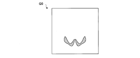
- the region of interest Q0, R0 on the standard data S is a partial region of the standard data S and represents the position, range, and size of the structure inside the standard brain.
- the regions of interest Q0 and R0 can be freely selected according to the purpose of diagnosis.
- the regions of interest Q0, R0 may be set in the hippocampus or in the cerebellar cortex.
- the conversion function acquisition unit 11 selects and averages an appropriate image set representing the morphology of the brain from a plurality of PET images D having the same cut surface obtained by dynamic PET imaging, and is actually measured by the PET apparatus.
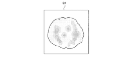
- a distribution form display image D1 showing the shape of the brain thus generated is generated.
- the distribution form display image D1 is an image in which the shape of the brain clearly appears as shown in FIG.
- An index used when the conversion function acquisition unit 11 selects the PET image D is, for example, the time taken from injection of radiopharmaceutical to imaging. It is known that when a radiopharmaceutical is injected, the radiopharmaceutical spreads throughout the brain in a certain time.
- the conversion function acquisition unit 11 adds the PET images D photographed before and after this time to generate the distribution form display image D1.
- This distribution form display image D1 represents the form of the brain actually measured by the PET apparatus.
- the conversion function acquisition unit 11 acquires the conversion function using the distribution form display image D1, and this principle will be described.
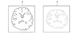
- the left side of FIG. 4 represents standard data S in which the standard brain is reflected. At this time, the standard data S is represented by a tomographic image for convenience of explanation.
- the right side of FIG. 4 is a virtual image A in which a structural image of the brain actually measured by the PET apparatus is reflected.
- This virtual image A is obtained by conventional static PET imaging or morphological image imaging. However, in the present invention, since static PET imaging and morphological image imaging are not performed, it is not an actually obtained image. Because of such circumstances, a virtual image A is represented by a broken line in FIG.
- the position of the hippocampus in the standard brain is known in advance. This is because the standard brain is generated from another morphological image such as an MRI image that shows the internal structure of the brain.
- the standardized PET image E includes a brain in the form of a standard brain. This standardized PET image E is, so to speak, a PET image when the brain imaged by the PET apparatus has a standard brain shape. That is, no other hippocampus is located in the area on the standardized PET image E at the same position as the hippocampus in the standard brain. Thus, if the position of a structure such as the hippocampus is determined in advance on the standard brain, the position of the hippocampus can be known for the brain actually measured by the PET apparatus.
- a plurality of standardized PET images E are sent to the image analysis unit 13.
- the image analysis unit 13 performs image analysis on the standardized PET image E by generating a parametric image Pa representing the concentration change of the radiopharmaceutical in the entire brain. That is, the image analysis unit 13 generates a parametric image Pa as shown in FIG.
- the parametric image Pa is generated by performing, for example, the following analysis for each pixel constituting the standardized PET image E. First, pixel values are obtained for each imaging point for a target part that exhibits a different behavior from a reference part that exhibits the same behavior regardless of whether it is healthy or disease among the pixels that constitute the standardized PET image E corresponding to the dynamic PET image D. Then, these are plotted on a graph in relation to the time of photographing by a mathematical method of time integration. By examining the slope when this plot is first-order approximated, it is possible to know whether the target site is a healthy site or a disease site.
- the left side of FIG. 9 schematically shows a region of interest R0 that is referred to when the quantitative analysis unit 14 operates.
- This region of interest R0 is a specific region in the standard brain.
- the quantitative analysis unit 14 recognizes the equivalent part R1 on the parametric image Pa at the same position as the part of interest R0 of the standard data S representing the standard brain (see the right side of FIG. 9), and acquires a representative value in the equivalent part R1.
- the representative value in the equivalent part R1 is a value representing the inside of the equivalent part R1, and may be, for example, an average value of pixel values in the equivalent part R1, or a maximum value of pixel values in the equivalent part R1.
- the quantitative analysis unit 14 quantifies the representative value inside the corresponding region R1 based on the acquired pixel value. Based on this numerical value, it can be determined whether or not the distribution state of the radiopharmaceutical reflected in the PET image D is abnormal.
- the mode of acquiring the representative value in the equivalent region R1 from the parametric image Pa has been described.
- the representative value of the radioactivity concentration in the equivalent region R1 is acquired based on the radioactivity concentration for each pixel on the standardized PET image E. Then, the inclination value may be examined using the value to obtain a representative value in the corresponding region R1.
- the normalized parametric image Pa is sent to the comparison unit 15.
- the comparison unit 15 reads the parametric image Pa related to the past analysis result stored in the storage unit 20 and automatically compares the two images by a series of operations by acquiring these differences. If such a comparison is performed on the same subject, the progression of the lesion in the subject's brain can be known. Further, if such a comparison is performed on different subjects, it becomes easy to compare the subjects.
- the comparison unit 15 may analyze the parametric image Pa acquired this time using other parametric images.
- the region-of-interest personalization unit 16 acquires the conversion function F from the conversion function acquisition unit 11. Then, the region-of-interest personalization unit 16 obtains an inverse transformation function F ⁇ 1 that is an inverse function of the transformation function F.
- the inverse transformation function F ⁇ 1 is a function that outputs a PET image D when applied to a standardized PET image E as shown in FIG. 10, for example.
- the region-of-interest personalization unit 16 changes the region of interest Q0, R0 on the standard data S in such a deformation manner that the shape of the brain indicated by the standard data S becomes the shape of the subject's brain reflected in the PET image D. And the region of interest on the PET image D is acquired.
- the tomographic image analysis apparatus 1 performs PET so that the brain form of the subject reflected in the PET image D is the brain form indicated by the standard data S prior to the tomographic image analysis.
- An image standardization unit 12 that deforms the image D is provided. Therefore, according to the present invention, there is no need to acquire a static PET image or a morphological image for knowing the brain morphology of the subject's brain reflected in the PET image D. Thereby, compared with the conventional method, the present invention can reduce the burden on the subject.
- the following analysis is performed on the standardized PET image E generated after deformation. That is, the analysis of the temporal change of the radiopharmaceutical distribution is automatically executed in a series of operations for the corresponding portion R1 on the standardized PET image E corresponding to the region of interest R0 on the standard data S. By doing so, the analysis result can be made stable with high accuracy.
- the region of interest is manually set for the PET image D. With such a configuration, it is impossible to stably divide the range of structures in the brain, and analysis of dynamic PET images is impossible.
- the region of interest can be automatically set, and the time change due to the elapsed time in the region of interest in the dynamic PET image can be automatically acquired. Therefore, there is no room for subjectivity to enter the analysis, and the result of the analysis is stabilized with high accuracy.
- the site of interest individualization unit 16 that acquires the site of interest on the PET image D by deforming the site of interest on the standard data S is provided.
- the site of interest individualization unit 16 that acquires the site of interest on the PET image D by deforming the site of interest on the standard data S is provided.
- the conversion function F is a function that transforms a two-dimensional image vertically and horizontally.
- the conversion function F may be a function that deforms in the vertical and horizontal height directions as three-dimensional voxel data.
- the PET image D is an image on a certain position plane. Actually, in imaging using the PET apparatus, a plurality of PET images D are acquired on different cutting planes parallel to each other in one imaging. Is done. Therefore, if each PET image D is arranged on the corresponding cut surface, voxel data in which the radiopharmaceuticals are three-dimensionally arranged can be acquired. Since the PET image D is repeatedly photographed at different time points, a plurality of voxel data in which radiopharmaceuticals at different time points are three-dimensionally arranged can be obtained by photographing using the PET apparatus.
- the conversion function acquisition unit 11 compares the three-dimensional form of the subject's brain reflected in the voxel data with the three-dimensional form of the brain indicated by the standard data S, thereby obtaining the brain of the subject reflected in the voxel data.
- a conversion function F that transforms the three-dimensional form into the three-dimensional form of the standard data is acquired.
- the tomographic image analysis apparatus 1 has been described so as to analyze an image acquired by a PET apparatus, but the present invention is not limited to this and is used for analysis of an image obtained by a SPECT apparatus. Can also be used.
- D PET image (dynamic distribution image) E Standardized distribution image P Pattern Q0 Region of interest R0 Region of interest R1 Equivalent region S Standard data 11 Conversion function acquisition unit (conversion function acquisition means) 12 Image standardization section (distributed image standardization means) 13 Image analysis unit (analysis means, normalization means) 14 Quantitative analysis section (analysis means) 15 Comparison part (comparison means) 16 Region-of-interest personalization unit (region-of-interest personalization means) 20 storage unit (storage means)
Landscapes
- Health & Medical Sciences (AREA)
- Engineering & Computer Science (AREA)
- Life Sciences & Earth Sciences (AREA)
- Medical Informatics (AREA)
- Radiology & Medical Imaging (AREA)
- Nuclear Medicine, Radiotherapy & Molecular Imaging (AREA)
- General Health & Medical Sciences (AREA)
- Physics & Mathematics (AREA)
- Biomedical Technology (AREA)
- Molecular Biology (AREA)
- Veterinary Medicine (AREA)
- Biophysics (AREA)
- Optics & Photonics (AREA)
- Pathology (AREA)
- Public Health (AREA)
- Animal Behavior & Ethology (AREA)
- Heart & Thoracic Surgery (AREA)
- High Energy & Nuclear Physics (AREA)
- Surgery (AREA)
- Dentistry (AREA)
- Oral & Maxillofacial Surgery (AREA)
- Neurology (AREA)
- Neurosurgery (AREA)
- Quality & Reliability (AREA)
- Computer Vision & Pattern Recognition (AREA)
- General Physics & Mathematics (AREA)
- Theoretical Computer Science (AREA)
- Nuclear Medicine (AREA)
Description
すなわち、従来の画像解析では、動的PET撮影の他に静的PET撮影や形態画像の撮像を行わなければならない。従来方法によれば、動的PET画像の解析をするには、静的PET撮影や形態画像の撮影が必要なのである。つまり、それだけ診断に長い時間を要するということになる。
すなわち、本発明に係る断層画像解析装置は、放射性薬剤の分布を示す断層画像である動的分布画像を解析する断層画像解析装置であって、標準的な脳の形状を示す標準データを予め記憶する記憶手段と、動的分布画像に写り込んだ被検体の脳の形態が標準データが示す脳の形態となるように動的分布画像の各々を変形させることにより、放射性薬剤の分布が標準化された標準化分布画像を動的分布画像の各々について生成する分布画像標準化手段と、標準データに基づいて放射性薬剤分布の時間的変化の解析を実行する解析手段とを備えることを特徴とするものである。
実施例1に係る断層画像解析装置1は、図1に示すように、PET装置で撮影されたPET画像Dを入力すると、種々の画像処理がなされて、動的に取得されたPET画像Dに写り込んだ放射性薬剤の分布状況が異常であるかどうか画像解析部13により判定される構成となっている。すなわち、本発明の断層画像解析装置1は、放射性薬剤の分布を示す断層画像であるPET画像Dの解析を目的とするものである。
断層画像解析装置1の全体構成について説明する。断層画像解析装置1は、PET画像Dを変形して標準データに合わせるよう変形させる画像標準化部12と、画像標準化部12がPET画像Dを変形する際に用いる変換関数Fを取得する変換関数取得部11とを備えている。また、断層画像解析装置1は、標準化されたPET画像Dについて放射性薬剤分布の時間変化を解析する画像解析部13および定量解析部14を備えている。比較部15は、画像解析部13の解析結果と、過去に画像解析部13が出力した解析結果あるいは予め正常被検体についての画像解析部13が出力した解析結果とを比較する構成である。関心部位個別化部16は、実測の脳の関心部位の位置、範囲、大きさを取得するための構成でありその具体的構成は後述のものとする。
図2は、記憶部20が記憶する標準的な脳の形状がデータ化された標準データSを概念的に表したものである。標準データSは、図2左側に示すように標準脳の形状が3次元的に表された3次元画像データとなっている。標準脳とは、脳内部位が同定できる基準となる脳の形態である。そしてこの標準データSは、標準脳の内部の構造をも表したデータである。したがって、図2左側の標準脳をある裁断面で裁断するように2次元画像を生成すると図2右側に示すように脳の内部構造が現れる。この標準脳は、どの位置がどの構造体に当たるか既に解析がなされている。したがって、標準データSを構成する範囲のどの部分が海馬に相当し、どの部分が小脳皮質に相当するか全て解析済みである。
続いて、断層画像解析装置の動作について説明する。本発明の最大の特徴は、関心部位と特定するための静的PET撮影や形態画像撮影をPET撮影前後に個別に行わなくても動的PET撮像単独で断層画像解析が完結することにある。この構成について詳しく説明する。まず、PET装置で撮影されたPET画像Dは、変換関数取得部11に送出される。変換関数取得部11は、PET画像Dおよび標準データSを基にPET画像Dに写り込んだ被検体の脳の形状を標準データの形状に変形させるような変換関数Fを取得する。
変換関数取得部11は、動的PET撮影による裁断面が同一となっている複数のPET画像Dのうちから脳の形態を表している適切な画像セットを選んで加算平均し、PET装置で実測された脳の形状を示す分布形態表示画像D1を生成する。この分布形態表示画像D1は、図3に示すように、脳の形状がはっきりと現れた画像となっている。変換関数取得部11がPET画像Dを選択する際に指標となるのは、例えば放射性薬剤の注射から撮影までにかかった時間である。放射性薬剤を注射すると、ある一定の時間で放射性薬剤が脳の全体に行き渡ることが知られている。変換関数取得部11は、この時間前後に撮影されたPET画像Dを合計して分布形態表示画像D1を生成するのである。この分布形態表示画像D1は、PET装置で実測された脳の形態を表している。
例えばPET画像Dに海馬の断面が含まれているものとする。海馬は、PET画像Dの内部のいずれかに位置しているのであるが、PET画像Dを見ても、どの部分が海馬であるかが分からない。PET画像Dは、放射性薬剤の分布を表したにすぎないからである。いま、PET画像Dに変換関数Fを作用させると、PET画像D上の脳全体の形態が変形されて標準脳の形態になるのに合わせて、PET画像D上の海馬に当たる部分も同じように変形される。しかし、PET画像Dに変換関数Fを作用させて生成された標準化PET画像Eだけ眺めても画像上の海馬の位置を推量することは難しい(図6参照)。
変換関数Fは、画像標準化部12に送出される。画像標準化部12は、動的なPET画像Dの各々に変換関数Fを作用させて標準化PET画像EをPET画像Dの各々について生成する。これにより、PET画像Dの各々に写り込んだ被検体の脳の形態は標準データSが示す脳の形態となるようにPET画像Dの変形が行われ、放射性薬剤の分布が標準化される。標準化PET画像Eを対応するPET画像Dの撮影順に見ていけば、PET装置の撮影に用いた脳が仮に標準脳の形状となっていたときの放射性薬剤の分布の推移を知ることができる。ところで動的に取得されたPET画像Dには、脳の全体像が写り込んでいるものと写り込んでいないものとがある。ということは、画像標準化部12は、被検体の脳の形態が写り込んだPET画像D及び被検体の脳の形態が写り込んでいないPET画像Dを含む撮影時点の異なるPET画像Dに対して変形を施すことになる。
複数の標準化PET画像Eは、画像解析部13に送出される。画像解析部13は、脳全体の放射性薬剤の濃度変化を表したパラメトリック画像Paを生成することで標準化PET画像Eについての画像解析を行う。すなわち、画像解析部13は、図7に示すようなパラメトリック画像Paを生成する。このパラメトリック画像Paは、標準化PET画像Eを構成する画素ごとに例えば次のような解析を行うことで生成される。まず、動的なPET画像Dに対応する標準化PET画像Eを構成する画素のうち、健常・疾患に関わらず同じ挙動を示す参照部位と異なる挙動を示す目的部位について画素値を撮影時点ごとに取得し、時間積分の数学的な手法によりこれらを撮影時点と関連させてグラフ上にプロットする。このプロットを一次近似させたときの傾きを調べることにより、目的部位が健常部位か疾患部位であるかを知ることができる。
パラメトリック画像Paは、画像の定量解析を行う定量解析部14に送出される。定量解析部14が行う具体的な動作について説明する。定量解析部14は、画像解析部13より正規化後のパラメトリック画像Paを取得する。そして、定量解析部14は、記憶部20より関心部位R0を表すデータを一連の操作で自動的に読み出す。
また、正規化後のパラメトリック画像Paは、比較部15に送出される。比較部15は、記憶部20に記憶された過去の解析結果に関するパラメトリック画像Paを読み出して、これらの差分を取得するなどして両画像の比較を一連の操作で自動的に行う。仮に、同一の被検体に対してこの様な比較を行えば、被検体の脳の病変の進行を知ることができる。また、異なる被検体に対してこの様な比較を行えば、被検体同士の比較が容易となる。
関心部位個別化部16は、PET装置で実測された脳の形態に則して関心部位Q0,R0を変形させることにより、実測の脳における関心部位の形状を推定する目的で設けられている。関心部位個別化部16は、標準化された関心部位の形状を実測の脳に当てはめて個別化する機能を有している。
E 標準化分布画像
P パターン
Q0 関心部位
R0 関心部位
R1 相当部位
S 標準データ
11 変換関数取得部(変換関数取得手段)
12 画像標準化部(分布画像標準化手段)
13 画像解析部(解析手段、正規化手段)
14 定量解析部(解析手段)
15 比較部(比較手段)
16 関心部位個別化部(関心部位個別化手段)
20 記憶部(記憶手段)
Claims (10)
- 放射性薬剤の分布を示す断層画像である動的分布画像を解析する断層画像解析装置であって、
標準的な脳の形状を示す標準データを予め記憶する記憶手段と、
前記動的分布画像に写り込んだ被検体の脳の形態が前記標準データが示す脳の形態となるように前記動的分布画像の各々を変形させることにより、放射性薬剤の分布が標準化された標準化分布画像を前記動的分布画像の各々について生成する分布画像標準化手段と、
前記標準データに基づいて放射性薬剤分布の時間的変化の解析を実行する解析手段とを備えることを特徴とする断層画像解析装置。 - 請求項1に記載の断層画像解析装置において、
前記動的分布画像のうちから脳の形態が認識できる選択された分布形態表示画像と前記標準データが示す脳の形態とを比較することにより、前記分布画像標準化手段が前記動的分布画像を変形する際に用いる変換関数を取得する変換関数取得手段を備えることを特徴とする断層画像解析装置。 - 請求項1または請求項2に記載の断層画像解析装置において、
前記標準データ上の関心部位を予め記憶する記憶手段を備え、
前記解析手段は、前記標準データ上の関心部位に相当する前記標準化分布画像上の相当部位について放射性薬剤分布の時間的変化の解析を実行することを特徴とする断層画像解析装置。 - 請求項3に記載の断層画像解析装置において、
前記解析手段の解析結果を、前記標準化分布画像上の相当部位における解析結果に基づき正規化する正規化手段とを備えることを特徴とする断層画像解析装置。 - 請求項1ないし請求項4のいずれかに記載の断層画像解析装置において、
前記記憶手段は、放射性薬剤の時間変化のパターンを記憶し、
前記解析手段の解析結果と前記パターンとを比較する比較手段を備えることを特徴とする断層画像解析装置。 - 請求項5に記載の断層画像解析装置において、
前記記憶手段は、前記解析手段が出力した正常脳の解析結果を記憶し、
前記比較手段は、前記解析手段の解析結果と、正常脳の解析結果との比較を行うことを特徴とする断層画像解析装置。 - 請求項5に記載の断層画像解析装置において、
前記記憶手段は、前記解析手段が出力した過去の解析結果を記憶し、
前記比較手段は、前記解析手段の解析結果と、過去の解析結果との比較を行うことを特徴とする断層画像解析装置。 - 請求項1ないし請求項7のいずれかに記載の断層画像解析装置において、
前記標準データが示す脳の形状が前記動的分布画像に写り込んだ被検体の脳の形状となるような変形様式で前記標準データ上の関心部位を変形し、前記動的分布画像上の関心部位を取得する関心部位個別化手段を備えることを特徴とする断層画像解析装置。 - コンピュータに放射性薬剤の分布を示す断層画像である動的分布画像の解析を実行させる解析プログラムであって、
コンピュータを
前記コンピュータに予め記憶された標準的な形状を示す標準データを読み出す標準データ読み出し手段と、
前記動的分布画像に写り込んだ被検体の脳の形態が前記標準データが示す脳の形態となるように前記分布画像の各々を変形させることにより、放射性薬剤の分布が標準化された標準化分布画像を前記動的分布画像の各々について生成する分布画像標準化手段と、
前記標準データに基づいて放射性薬剤分布の時間的変化の解析を実行する解析手段として機能させることを特徴とする解析プログラム。 - 請求項9に記載の解析ブログラムを記憶する記憶媒体。
Priority Applications (2)
| Application Number | Priority Date | Filing Date | Title |
|---|---|---|---|
| JP2014533047A JP5996658B2 (ja) | 2012-08-30 | 2013-08-28 | 脳断層動態画像解析装置 |
| US14/424,870 US9715728B2 (en) | 2012-08-30 | 2013-08-28 | Brain tomographic dynamic image analyzing apparatus |
Applications Claiming Priority (2)
| Application Number | Priority Date | Filing Date | Title |
|---|---|---|---|
| JP2012190107 | 2012-08-30 | ||
| JP2012-190107 | 2012-08-30 |
Publications (1)
| Publication Number | Publication Date |
|---|---|
| WO2014034724A1 true WO2014034724A1 (ja) | 2014-03-06 |
Family
ID=50183531
Family Applications (1)
| Application Number | Title | Priority Date | Filing Date |
|---|---|---|---|
| PCT/JP2013/073007 Ceased WO2014034724A1 (ja) | 2012-08-30 | 2013-08-28 | 脳断層動態画像解析装置 |
Country Status (3)
| Country | Link |
|---|---|
| US (1) | US9715728B2 (ja) |
| JP (1) | JP5996658B2 (ja) |
| WO (1) | WO2014034724A1 (ja) |
Cited By (3)
| Publication number | Priority date | Publication date | Assignee | Title |
|---|---|---|---|---|
| JP2015190763A (ja) * | 2014-03-27 | 2015-11-02 | 富士フイルムRiファーマ株式会社 | コンピュータプログラム、画像処理装置及び方法 |
| WO2021245733A1 (ja) * | 2020-06-01 | 2021-12-09 | 日本電気株式会社 | 脳画像解析装置、制御方法、及びコンピュータ可読媒体 |
| US11972564B2 (en) | 2020-08-14 | 2024-04-30 | Splink, Inc. | Recording medium, information processing device, information processing method, trained model generation method, and correlation image output device |
Families Citing this family (3)
| Publication number | Priority date | Publication date | Assignee | Title |
|---|---|---|---|---|
| CN107480673B (zh) * | 2017-06-30 | 2021-01-26 | 上海联影医疗科技股份有限公司 | 确定医学图像中感兴趣区域的方法、装置及图像编辑系统 |
| TWI860680B (zh) | 2023-04-11 | 2024-11-01 | 臺北醫學大學 | 腦部類澱粉蛋白正子造影處理系統及其運作方法 |
| CN117974584B (zh) * | 2024-01-22 | 2024-09-10 | 暨南大学附属第一医院(广州华侨医院) | 一种脑影像的分析方法、系统及计算机存储介质 |
Citations (3)
| Publication number | Priority date | Publication date | Assignee | Title |
|---|---|---|---|---|
| JP2007113945A (ja) * | 2005-10-18 | 2007-05-10 | Joji Nakagawara | 画像処理方法、画像処理プログラム、及び画像処理装置 |
| JP2009505709A (ja) * | 2005-08-25 | 2009-02-12 | コーニンクレッカ フィリップス エレクトロニクス エヌ ヴィ | 標的療法のための画像ベースの計画方法及び装置 |
| JP2011203009A (ja) * | 2010-03-24 | 2011-10-13 | Toshiyuki Ogura | 画像処理装置、プログラムおよび画像処理方法 |
Family Cites Families (7)
| Publication number | Priority date | Publication date | Assignee | Title |
|---|---|---|---|---|
| CN1325933C (zh) * | 2000-08-21 | 2007-07-11 | V-目标技术有限公司 | 对坐标系统中放射性辐射源成像的系统 |
| JP4454212B2 (ja) | 2001-08-31 | 2010-04-21 | 富士フイルムRiファーマ株式会社 | 画像関連データ処理方法 |
| JP4025524B2 (ja) * | 2001-09-28 | 2007-12-19 | 富士フイルムRiファーマ株式会社 | 異条件下における脳機能画像の画像間差補正法 |
| EP1778957A4 (en) * | 2004-06-01 | 2015-12-23 | Biosensors Int Group Ltd | OPTIMIZING THE MEASUREMENT OF RADIOACTIVE RADIATION ON SPECIAL BODY STRUCTURES |
| US7872235B2 (en) * | 2005-01-13 | 2011-01-18 | Spectrum Dynamics Llc | Multi-dimensional image reconstruction and analysis for expert-system diagnosis |
| WO2007023522A1 (ja) * | 2005-08-22 | 2007-03-01 | National Center Of Neurology And Psychiatry | 脳疾患の診断支援方法及び装置 |
| CA2738124A1 (en) * | 2008-09-22 | 2010-03-25 | Nihon Medi-Physics Co., Ltd. | Device for creating database of alternative normal brain |
-
2013
- 2013-08-28 WO PCT/JP2013/073007 patent/WO2014034724A1/ja not_active Ceased
- 2013-08-28 JP JP2014533047A patent/JP5996658B2/ja active Active
- 2013-08-28 US US14/424,870 patent/US9715728B2/en not_active Expired - Fee Related
Patent Citations (3)
| Publication number | Priority date | Publication date | Assignee | Title |
|---|---|---|---|---|
| JP2009505709A (ja) * | 2005-08-25 | 2009-02-12 | コーニンクレッカ フィリップス エレクトロニクス エヌ ヴィ | 標的療法のための画像ベースの計画方法及び装置 |
| JP2007113945A (ja) * | 2005-10-18 | 2007-05-10 | Joji Nakagawara | 画像処理方法、画像処理プログラム、及び画像処理装置 |
| JP2011203009A (ja) * | 2010-03-24 | 2011-10-13 | Toshiyuki Ogura | 画像処理装置、プログラムおよび画像処理方法 |
Cited By (3)
| Publication number | Priority date | Publication date | Assignee | Title |
|---|---|---|---|---|
| JP2015190763A (ja) * | 2014-03-27 | 2015-11-02 | 富士フイルムRiファーマ株式会社 | コンピュータプログラム、画像処理装置及び方法 |
| WO2021245733A1 (ja) * | 2020-06-01 | 2021-12-09 | 日本電気株式会社 | 脳画像解析装置、制御方法、及びコンピュータ可読媒体 |
| US11972564B2 (en) | 2020-08-14 | 2024-04-30 | Splink, Inc. | Recording medium, information processing device, information processing method, trained model generation method, and correlation image output device |
Also Published As
| Publication number | Publication date |
|---|---|
| JP5996658B2 (ja) | 2016-09-21 |
| JPWO2014034724A1 (ja) | 2016-08-08 |
| US20150235358A1 (en) | 2015-08-20 |
| US9715728B2 (en) | 2017-07-25 |
Similar Documents
| Publication | Publication Date | Title |
|---|---|---|
| JP5996658B2 (ja) | 脳断層動態画像解析装置 | |
| CN101626727B (zh) | 附加有pet/mr流动估计的自动诊断和对准 | |
| CN103040479B (zh) | 可能的灌注缺陷的确定 | |
| EP1473674A1 (en) | Improvements in or relating to dynamic medical imaging | |
| JP6442311B2 (ja) | 核医学画像中の腫瘍輪郭を抽出する技術 | |
| US9078622B2 (en) | Method and apparatus for data selection for positron emission tomogrpahy (PET) image reconstruction | |
| JP4025524B2 (ja) | 異条件下における脳機能画像の画像間差補正法 | |
| US10395364B2 (en) | Nuclear medical image analysis technique | |
| HK1243299A1 (zh) | 心肌核医学图像数据的解析方法和解析装置 | |
| US7650021B2 (en) | Device and method for determining the concentration of a tracer in blood | |
| US8837799B2 (en) | Method and apparatus for selecting a reference gate | |
| JP5930193B2 (ja) | Spect画像の画像変換装置、画像変換プログラム、および画像変換方法 | |
| JP5689205B1 (ja) | 頭部核医学画像の評価法 | |
| Klumpers et al. | Parametric [11C] flumazenil images | |
| EP3794606B1 (en) | Systems, methods, and apparatuses for generating regions of interest from voxel mode based thresholds | |
| JP6277036B2 (ja) | コンピュータプログラム、画像処理装置及び方法 | |
| JP6442310B2 (ja) | 核医学画像中の腫瘍領域を抽出する技術 | |
| Lopes Alves et al. | Parametric imaging of [11C] Flumazenil binding in the rat brain | |
| Wakabayashi et al. | Quantification of myocardial perfusion defect size in rats: comparison between quantitative perfusion SPECT and autoradiography | |
| JP7240664B2 (ja) | 画像診断支援装置、画像診断支援方法および画像診断支援プログラム | |
| Alves et al. | Parametric imaging of [11C] flumazenil binding in the rat brain | |
| JP2017219531A (ja) | 心筋核医学画像データの解析方法及び解析装置 | |
| CN120167982A (zh) | 医学图像的构建方法、构建装置、计算机设备和存储介质 | |
| HK1232608A1 (en) | Method for evaluating nuclear medicine image of head |
Legal Events
| Date | Code | Title | Description |
|---|---|---|---|
| 121 | Ep: the epo has been informed by wipo that ep was designated in this application |
Ref document number: 13833778 Country of ref document: EP Kind code of ref document: A1 |
|
| ENP | Entry into the national phase |
Ref document number: 2014533047 Country of ref document: JP Kind code of ref document: A |
|
| WWE | Wipo information: entry into national phase |
Ref document number: 14424870 Country of ref document: US |
|
| NENP | Non-entry into the national phase |
Ref country code: DE |
|
| 122 | Ep: pct application non-entry in european phase |
Ref document number: 13833778 Country of ref document: EP Kind code of ref document: A1 |