WO2014034330A1 - ソフトウェア検証用プログラムおよびソフトウェア検証システム - Google Patents
ソフトウェア検証用プログラムおよびソフトウェア検証システム Download PDFInfo
- Publication number
- WO2014034330A1 WO2014034330A1 PCT/JP2013/069967 JP2013069967W WO2014034330A1 WO 2014034330 A1 WO2014034330 A1 WO 2014034330A1 JP 2013069967 W JP2013069967 W JP 2013069967W WO 2014034330 A1 WO2014034330 A1 WO 2014034330A1
- Authority
- WO
- WIPO (PCT)
- Prior art keywords
- variable
- model
- external environment
- unit
- software
- Prior art date
- Legal status (The legal status is an assumption and is not a legal conclusion. Google has not performed a legal analysis and makes no representation as to the accuracy of the status listed.)
- Ceased
Links
Images


Classifications
-
- G—PHYSICS
- G06—COMPUTING OR CALCULATING; COUNTING
- G06F—ELECTRIC DIGITAL DATA PROCESSING
- G06F11/00—Error detection; Error correction; Monitoring
- G06F11/36—Prevention of errors by analysis, debugging or testing of software
- G06F11/3604—Analysis of software for verifying properties of programs
Definitions
- the present invention relates to a software tool for analyzing the structure of software, and more particularly to a software tool for constructing a model for verification and attribute analysis of variables using a data flow.
- model checking as a technique for comprehensively verifying the state of the system.
- the system is replaced with a state transition model, the properties required for the system are defined as properties and assertions, and the state transition model is input to the tool together with the state transition model. Determine whether a given property or assertion is satisfied. If not satisfied, a counterexample is output.
- an external environment model such as hardware is used as a system verification model. It is necessary to create and synthesize a software model (a verification model that expresses software) and a verification model that expresses the external environment for.
- a software model a verification model that expresses software
- a verification model that expresses the external environment for.
- a state search incomplete problem called a state explosion
- the external environment model simulates the behavior of other parts that are not the inspection target from the state transition information of the part that is the inspection target in the software. It generates message communications. For this reason, the external environment model cannot be generated without the state transition information of the software to be inspected. In addition, the external environment model cannot take behaviors that are not assumed by software, such as failures.
- the present invention has been made in view of such problems, and an object of the present invention is to create a software model when creating and synthesizing an external environment model such as hardware and a software model as a system verification model. It is to reduce the trouble of matching input and output with the external environment model.
- the present invention provides an inspection model generation program that receives a source code of software to be verified as an input, analyzes the source code, and generates a model for model checking.
- a dependency analysis unit for deriving dependency relationships such as variables of the source code in a computer, a variable attribute recording unit for recording attribute information for some variables of the source code, and the dependency relationship and the variable attribute recording unit.
- a variable attribute interpretation unit that infers an attribute for each variable of the source code from the attribute information, and a variable attribute information display unit that displays the attribute information are configured.
- an external environment model database and an external environment model candidate extraction unit that extracts a usable model from the external environment model database according to the variable attribute information are configured.
- a dependency limiting unit that accepts a range limitation specification for the dependency, a source code extracting unit that performs slicing of source code from the limited dependency, and an inspection from the extracted source code
- a model conversion unit that generates a software model for use, an external environment model selection unit that selects a model to be used from models extracted by the external environment model candidate extraction unit, the software model, and the external environment model selection unit
- a system model synthesis unit that synthesizes a system model for inspection from the external environment model.
- the inspection model generation program extracts from the database what can be used as the external environment model from the variable attribute information including the inferred one, thereby reducing the man-hours required for the user of the program to select the external environment model. can do.
- the inspection model generation program searches the database for an external environment model that can be connected to the software model after slicing from the attribute information of the variable having a dependency relationship with the selected variable. , Present as a candidate.
- the variable of the software that can be connected is searched from the attributes of the input and output variables of the external environment model, and set as a slicing condition (slice standard), so that the selected external environment is selected. Extract the source code that is the source of conversion of the software model that can be connected to the model. As described above, the number of man-hours required for the user to model both hardware and software for verification can be reduced.
- FIG. 1 shows a system configuration when the present invention is realized as a system.
- the present invention is realized as a software tool, for example.
- software for executing processing is stored as a verification model generation program 1131 in, for example, the ROM 113 on the computer 11, read by the CPU 111, and executed using the RAM 112 as a working storage area.
- the computer 11 executes processing defined by the verification model generation program 1131.
- the processing contents will be described in FIG.
- the source code file to be analyzed is stored in a storage device such as the hard disk 114 on the computer 11.
- User operations such as analysis execution instructions can be performed from the input device 12 such as a keyboard.
- the output by the verification model generation program 1131 is output to the display device 13 such as a display, for example, but in addition to this, output via a network to an external computer (not shown) and data to an external storage medium such as a CD-ROM It may be output by writing in a file format.
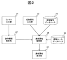
- FIG. 2 shows a basic functional configuration of the verification model generation program 1131.
- the file input unit 21 has a function that allows the user to select one or more source code files to be analyzed, and reads the source code file from a computer storage medium (such as the hard disk 114) according to the file designation by the user.
- the dependency relationship analysis unit 22 analyzes the source code file read by the file input unit 21 and derives the dependency relationship of the program generated from the source code.
- the dependency relationship is a relationship that can affect the operation result depending on the execution order of the program.
- the dependency relationship between statements is a program dependency relationship between statements
- a variable relationship is a dependency relationship between variables. It is a dependency.
- the program dependency is divided into variable units, it becomes a variable dependency. Therefore, the program dependency and the variable dependency can be regarded as equivalent as information.
- the method for deriving the program dependency relationship and the variable dependency relationship is left to the literature and is omitted in this specification.
- variable attribute input unit 23 receives an input from the user regarding an attribute related to a certain variable described in the source code.
- variable attributes refer to those related to input / output matching of the software model.
- the variable attribute database 24 records attribute information for some variables of the source code read by the file input unit 21.
- the variable attribute interpretation unit 25 is described in the source code from the dependency relationship information derived by the dependency relationship analysis unit 22 and the variable attribute information possessed by either or both of the variable attribute input unit 23 and the variable attribute database 24. Infer as much as possible about the attributes of each variable.
- the rules recorded in the inference rule database 26 are used for inference.
- the variable attribute display unit 27 displays the variable attribute information inferred by the variable attribute interpretation unit 25 on the display device 13 together with the variable attribute information held by the variable attribute input unit 23 and the variable attribute database 24.
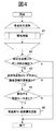
- FIG. 3 is a process performed by the verification model generation program 1131 using the function shown in FIG. 2, and shows a flow of a process for inferring attribute information of variables described in the input source code.
- the dependency analysis unit 22 analyzes the dependency of the input source code and outputs it as data.
- the variable dependency can be expressed as “a ⁇ b”. This means that the variable b affects the variable a. Conversely, “a ⁇ b” may be described, and an expression rule may be determined. In the present embodiment, the former is adopted. Also, a is called the dependency source and b is called the dependency destination.
- step 32 the variable attribute interpretation unit 25 acquires variable attribute information described in the input source code from the variable attribute input unit 23 or the variable attribute database 24, and outputs the dependency relationship analysis unit 22. Is associated with each variable in the dependency data. Note that step 32 is executed only when the attribute information of the corresponding variable is empty, and is skipped otherwise.
- the variable attribute interpretation unit 25 extracts the variable that is the starting point of the attribute inference process in the dependency relationship data.
- the attribute information is inferred forward (from the dependency destination variable to the dependency source variable) based on the attribute information of the input variable. Shall proceed. Further, the processing of this embodiment is recursive. For this reason, a variable that does not have an influence variable, that is, is not dependent on any variable (there is no variable that becomes a dependency source) is extracted as a starting variable. However, if the dependency relationship is looped and there is no corresponding variable, one arbitrary variable is selected.
- step 34 the variable attribute interpretation unit 25 performs an attribute inference process (details are described in FIG. 4) for each target starting variable.
- Step 34 is executed for each of the variables serving as inference start points extracted in step 33. The process is completed as described above.
- variable attribute display unit 27 displays the output dependency relationship information on the display device 13.
- FIG. 4 is a process for inferring attribute information of a variable, and shows a detailed flow of step 34 (“attribute inference” process) in FIG.
- step 41 is executed for each of the dependence source variables of the target variable for which the attribute information is inferred.
- the variable attribute interpretation unit 25 performs a process of inferring attribute information (the process of FIG. 4) for the target dependency source variable.
- step 42 the variable attribute interpretation unit 25 determines whether the target variable and the dependency source variable are in a data dependency relationship. If it is a data dependency relationship, it is not necessary to update the attribute information of the target variable, so the process is terminated. Otherwise, the process proceeds to step 43.
- step 43 the variable attribute interpretation unit 25 determines whether the attribute information of any dependency source variable has been updated in step 41. If even one variable has been updated, the process proceeds to step 44.
- step 44 the variable attribute interpretation unit 25 determines whether the target variable corresponds to the inference rule recorded in the inference rule database 26. If even one rule is applicable, the process proceeds to step 45. If there is no applicable rule, the attribute information of the target variable is held and the process is terminated.
- step 45 the variable attribute interpretation unit 25 executes an inference process based on the inference rule corresponding in step 44, and reflects the result in the attribute information of the target variable. The process is completed as described above. Note that the above is processing when the dependency relationship is not looped. If a loop exists, it is necessary to exclude the variable that has been subjected to the “attribute inference” processing once.
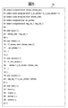
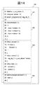
- the source code 50 in FIG. 5 is an example of source code described in C language that is input to the verification model generation program 1131 as an analysis target.
- the leftmost number is the line number.
- variable dependency relationship graph 61 is displayed on the display device 13, for example.
- the nodes of the variable dependency relationship graph 61 are variables that are distinguished not only by variable names and entities (storage areas) but also by description positions (and execution paths).
- a variable described as “stroke (L20 @ control)” means a variable stroke described in the function control on the 20th line of the source file.
- stroke L20 @ control
- each node has an attribute that can be found only from the source code, such as a variable type, an attribute given from the variable attribute input unit 23 or the variable attribute database 24,
- the attributes inferred by the variable attribute interpretation unit 25 are associated with each other and stored as data in the RAM 112 or the hard disk 114.
- data indicating the type of relationship is stored in association with an edge (arrow) indicating the dependency relationship and an edge (broken line) indicating the relationship in the arithmetic expression.
- def indicates that the dependency source variable is the definition of the dependency destination variable (a value is determined by assignment or the like).
- use indicates a data dependency relationship (the dependency source variable uses the value of the dependency destination variable).
- Cond indicates a control dependency relationship (the execution path changes depending on the value of the dependency destination variable, which affects the value of the dependency source variable).
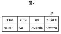
- variable attribute table 71 shows an example of variable attributes recorded in the variable attribute database 24.
- the variable attribute table 71 shown in FIG. Items in the variable attribute table 71 are composed of a variable name, in / out (whether the variable is a program input or output), a unit, and a data type. These values are preset.
- the variable reg_ad_1 is an input variable, and it can be seen that the data type is a stroke amount (for example, a brake pedal of an automobile).
- the unit is “(A / D conversion value)”, which is a value obtained by A / D (Analog / Digital) conversion, and indicates that the unit is not particularly determined.
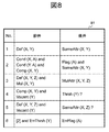
- the items in the inference rule table 81 include an antecedent and a consequent. This means that when the antecedent condition is satisfied, the antecedent condition is also satisfied.
- the antecedent and consequent are expressed in predicate logic. These values are preset.
- Inference rule No. in inference rule table 81 2, X, Y, and A indicate certain variables, and Cond (X, A) “A is in a control dependence relationship with X (A is a dependency source)” and Cond (Y, A) “A Is in a control dependence relationship with Y ”and Comp (X, Y)“ X and Y are in a size comparison relationship (connected by a size comparison symbol) in the arithmetic expression ”, Flag ( A) It means that “A is a determination flag (such as abnormality) and has no unit” and SameAttr (X, Y). Note that the data type to be determined by the flag A is, for example, the data type of the variable X.
- X, Y, and Z indicate certain variables, and Def (X, Y, Z) “X and Y define Z” and Mul (X, Y) “X and Y and Is a multiplication relationship in the arithmetic expression (connected by a multiplication symbol) ”, MulAttr (X, Y, Z)“
- the data type of Z is the same as X (or Y), and It means that the unit of Z is a product of X and Y.
- inference rules can be described for sum / difference and division.
- X and Y indicate certain variables. If Comp (X, Y) and Vacant (Y) “Y attribute is empty”, Thrsh (Y) “Y data type is“ threshold ” Is. However, “?” Attached to Thrsh (Y) means that it is not fixed. Note that the data type of the threshold Y is the data type of the variable X.
- Y and A indicate certain variables. If the antecedent of 2 is established and ErrThrsh (Y) “Y is an abnormal threshold value”, it means that ErrFlag (A) “A is an abnormal determination flag (flag indicating abnormality)”. The inference rule no. 2 is used. 6 is given priority. That is, the application of ErrFlag (A) is prioritized over Flag (A).
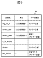
- FIG. 9 shows a variable attribute table 91 associated with the node of the variable dependency relationship graph 61, which contains values after the process of FIG. 3 is executed once.
- the items in the variable attribute table 91 are composed of variable names, units, and data types.
- variable attribute table variables are distinguished by substance, not by description position. For this reason, the node of the variable dependency relationship graph 61 and the row of the variable attribute table 91 have n: 1 correspondence. For example, for the variable stroke, the variable dependency relationship graph 61 has two corresponding nodes, but the variable attribute table 91 has only one corresponding row.
- variable attribute interpretation unit 25 receives the data of the variable dependency relationship graph 61 from the dependency relationship analysis unit 22, and generates the data structure of the variable attribute table 91 from the variables included in the variable dependency relationship graph 61. At this time, only the variable name is entered in the variable attribute table 91, and the remaining data is empty. A flag indicating that the attribute information of each variable is updated (not described in the variable attribute table 91) is cleared.
- variable attribute interpretation unit 25 acquires variable attribute information included in the variable dependency relationship graph 61 from the variable attribute table 71 of the variable attribute database 24. However, in this embodiment, only attribute information of input variables is acquired. Then, since attribute information regarding the variable reg_ad_1 is acquired, a value is entered in the variable attribute table 91. At this time, a flag indicating update of attribute information of the variable reg_ad_1 is set.
- variable attribute interpretation unit 25 extracts a variable that is an inference start of the variable dependency relationship graph 61. For all the nodes, the presence / absence of a variable serving as a dependency source is determined. If only the node determined not to exist is left, the variable stroke (L20 @ control) is extracted. For this variable, the variable attribute interpretation unit 25 performs the “attribute inference” process of FIG.
- the “attribute inference” process is executed for the variable stroke (L20 @ control)
- the “attribute inference” is a recursive process. The process is executed. Since the variable reg_ad_1 (L7 @ input) does not have a dependency destination variable, attribute information is held. This attribute information is the same as the value acquired from the variable attribute table 71.
- step 42 to 45 the processing of steps 42 to 45 is executed for the variable stroke_raw (L7 @ input). Since the attribute information of reg_ad_1 (L7 @ input) of the dependency destination variable has been updated by acquiring a value from the variable attribute table 71, a matching inference rule is searched from the inference rule table 81. No. as a matching inference rule. 1 is extracted (X of the inference rule is reg_ad_1, Y is stroke_raw), and the attribute of stroke_raw is updated to the same content as reg_ad_1.
- variable stroke_raw L16 @ convert
- variable stroke_raw L10 @ check
- the attribute information is not updated (updated).
- variable stroke_max (L10 @ check) is the inference rule No. of the inference rule table 81. 4, the data type is determined to be “threshold for stroke amount” and the unit is “(A / D conversion value)”. However, since it is not fixed, “?” Is added to the attribute value.
- the variable err_stroke (L11 @ check) is the inference rule No. of the inference rule table 81. 2 (the inference rule X is stroke_raw, Y is stroke_max, and A is err_stroke). From the flag (A) of the subsequent case, the data type is a determination flag for the stroke amount and the attribute type of the err_stroke is determined. So the unit is updated without any. Also, the attribute of stroke_max is updated to the same content as the stroke_raw from SameAttr (X, Y).
- variable err_stroke (L15 @ convert) is data dependency with err_stroke (L11 @ check), the attribute information is not updated.
- variable stroke (L16 @ convert) is the inference rule No. of the inference rule table 81. 3 (the inference rule X is stroke_raw, Y is c_in_stroke, and Z is stroke). However, since the attribute information of c_in_stroke is empty and unknown, the inference cannot proceed. On the other hand, the inference rule No. 5, the stroke data type is determined to be “stroke amount”. However, since it is not fixed, “?” Is added to the attribute value.
- the process of FIG. 3 is completed.
- the inference may be advanced backward based on the attribute information of the output variable.
- the attribute information of other variables can be automatically inferred from the attribute information of some variables, and the user can manually track the dependency of variables and interpret the attribute information. Instead, it is possible to obtain variable attribute information in a short time.
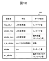
- FIG. 10 shows a variable attribute table 101 in which the variable attribute table 91 is updated by receiving the input of variable attribute information from the user and executing the inference process of FIG. 3 again.
- variable attribute table 91 After the value of the variable attribute table 91 is derived by the inference process, the user sets the data type of the variable stroke_max to “abnormal threshold” and the unit is “(A / D conversion value)” to the variable attribute input unit 23. Enter. As these attribute values, data types and units, and possible values for each, are prepared and displayed as candidates. The user visually checks the list on the display device 13, selects it from the input device 12, and confirms it. In the verification model generation program 1131, “threshold value”, “abnormal threshold value”, and the like are defined in advance as data type candidates. Further, “abnormal threshold” is defined as a subordinate concept of “threshold”.
- the verification model generation program 1131 executes the inference process of FIG. Then, the attribute information of the variable err_stroke is the inference rule No.
- the data type is “stroke amount abnormality determination flag”.
- the verification model generation program 1131 performs the inference processing of FIG. And the attribute information of the variable stroke is the inference rule No.
- the data type is “stroke amount” and the unit is “cm”.
- the unit system calculation rules are defined in the verification model generation program 1131 in the same manner as the inference rule table 81.
- FIG. 11 shows a functional configuration of the verification model generation program 1131, and these functions operate together with the basic functional configuration of FIG.
- the dependency relationship limiting unit 111 receives dependency relationship information regarding the source code to be analyzed from the dependency relationship analyzing unit 22 and individually determines whether or not each variable included in the dependency relationship information is to be left at the time of source code extraction (remaining setting). Data) and manage them.
- the remaining setting data is indicated by a binary value (True; leave, False; do not leave), and has a meaning of limiting the range used for source code extraction in the dependency relationship information.
- the initial value of the remaining setting data is, for example, True for all variables.
- the dependency relationship analysis unit 22 changes the remaining setting data in response to a user input or designation from the external environment model selection unit 116.
- the dependency relationship information when there is a dependency relationship between a variable that remains when extracting source code and a variable that does not remain, the remaining variable becomes the boundary between the software model and the external environment model.
- a boundary variable For example, in the variable dependency graph 61, when it is set that the stroke_raw (L7 @ input) is to be left and reg_ad_1 (L7 @ input) is not to be left, the stroke_raw (L7 @ input) is a boundary variable.
- the specified content from the user input or the external environment model selection unit 116 for the remaining setting data of the dependency analysis unit 22 may be the remaining setting of each variable or a variable specified for the boundary. For example, when stroke_raw (L7 @ input) is designated as a boundary variable on the input side, the remaining setting of stroke_raw (L7 @ input) is True, and the remaining setting of reg_ad_1 (L7 @ input) is False.
- the source code extraction unit 112 receives the source code to be analyzed from the file input unit 21, and extracts (slicing) the source code based on the dependency relationship information and the remaining setting data by the dependency relationship limiting unit 111.
- the extracted source code is output to a file.
- a slicing method for example, after the source code is parsed, among the variables included in the dependency relationship information, the statement in which the variable whose residual setting is True is described, and the syntax (function etc.) that includes the statement Leave the syntax (such as variable declarations) and remove the rest of the code.
- the model conversion unit 113 converts the source code after slicing output from the source code extraction unit 112 into a model description language that can be handled by the model checker.
- a model checker called SPIN (Simple Promela Interprinter)
- the model description language is Promela.
- As a model conversion method after parsing the source code, each syntax is converted based on a rule for converting from the syntax of the source code to the syntax of the model description language. This conversion rule is prepared in advance.
- the model obtained by the conversion is a verification model for the software to be inspected, and is a part of the verification model for the system to be inspected.
- the external environment model database 114 stores model parts that are templated for coding or automatic code generation in advance for the external environment of the software to be verified in association with attributes.
- the external environment model candidate extraction unit 115 receives the dependency relationship information associated with the remaining setting data from the dependency relationship limiting unit 111, and the attribute information of each variable of the software to be verified from the variable attribute interpretation unit 25, and the remaining setting
- the external environment model matching the interface is extracted from the external environment model database 114 by using a part of the attribute information (data item, unit, etc.) of the variable having “true” as a search key.
- the extracted external environment model is a model that can be an external environment of the software to be verified.
- the external environment model selection unit 116 displays a list of attributes (names, etc.) of the external environment model extracted by the external environment model candidate extraction unit 115 to the user using the display device 13, and each external environment from the user. A designation is accepted from the input device 12 as to whether the model is used. Use / non-use is “none” by default. When the user designates use / non-use as “Yes” for one of the external environment models, the attribute information of the variable that is the interface of the selected external environment model is passed to the dependency relationship limiting unit 111 and the dependency relationship is limited. The unit 111 searches the dependency information for a variable whose attribute matches the interface variable of the external environment model among the software variables to be verified, and changes the remaining setting as a boundary variable.
- the boundary variable is set to remain.
- the variable in the direction of the dependence source (which is closer to the output) from the boundary variable is changed to a setting that does not remain (for example, until a variable whose remaining setting is True appears).
- the variable from the boundary variable to the dependence destination direction (the closer to the input) is set not to remain.
- the change of the remaining setting is the reverse of the input.
- the external environment model selection unit 116 may output an external environment model in which the presence / absence of use is specified as “present” to a file.
- the model synthesis unit 117 synthesizes the verification model of the system to be verified from the software model output from the model conversion unit 113 and the external environment model designated by the external environment model selection unit 116 as being used. At this time, if there is attribute information that does not match between the interface variable of the external environment model and the boundary variable of the corresponding software, the attribute information of the interface variable of the external environment model is changed. For example, the name of the interface variable is changed to be the same as the name of the boundary variable.
- the synthesized verification model is output as a file to the hard disk 14.
- FIG. 12 is a process performed by the verification model generation program 1131 using the functions shown in FIG. 2 and FIG. 11, and shows a process flow for generating a system verification model.
- step 121 the verification model generation program 1131 performs the process of FIG. 3 to generate dependency information of the software to be verified.
- Dependency relationship information is passed from the dependency relationship analyzing unit 22 to the dependency relationship limiting unit 111 and managed.
- step 122 the external environment model candidate extraction unit 115 extracts external environment model candidates from the external environment model database 114 based on the dependency relationship information output in step 121.
- step 123 the verification model generation program 1131 confirms the user input from the input device 12. If the user input is to change the remaining setting of a variable, the process proceeds to step 124. If the user input is to change the use / non-use setting of an external environment model extracted by the external environment model candidate extraction unit 115, the process proceeds to step 125. If the user input indicates system verification model synthesis, the process proceeds to step 127.
- step 124 the dependency relationship limiting unit 111 changes the remaining setting of each variable in the dependency information according to the user input, and returns to step 122.
- step 122 the external environment model candidate is extracted again in response to the change in the remaining setting of each variable.
- step 125 the external environment model selection unit 116 changes the use / non-use setting of each external environment model in accordance with the user input, and proceeds to step 126.
- step 126 the dependency relationship limiting unit 111 searches the boundary variable corresponding to the verification target software from the attribute of the interface variable of the external environment model set to be used in step 125, and determines the dependency relationship. Change the remaining settings for each variable in the information. When the change is completed, the process returns to step 123.
- step 127 the source code extraction unit 112 extracts the source code by using the dependency relationship information given the variable remaining setting.
- step 129 the model synthesis unit 117 synthesizes and outputs a system verification model from the software verification model output in step 128 and the external environment model set to be used in step 125. . The process ends as described above.
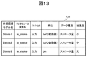
- variable attribute table 131 is linked to one external environment model, and the items are the external environment model name, interface variable name, in / out (whether the interface variable is input or output), unit (interface variable), ( It consists of data type (interface variable) and abstraction level (external environment model). These values are preset.
- the external environment model attribute table 131 three external environment models, Stroke1, Stroke2, and Stroke3, are registered, all of which have “stroke amount” as the data type of the interface variable and “input” as the input / output.
- the unit of the interface variable is “(A / D conversion value)” for Stroke 1 and Stroke 2, and “cm” for Stroke 3.
- the external environment model candidate extraction unit 115 receives the variable attribute table 101 of FIG. 10 from the variable attribute interpretation unit 25, and extracts an external environment model whose data type and unit match the external environment model attribute table 131. Then, Stroke 1 and Stroke 2 are extracted for the variables reg_ad — 1 and stroke_raw, and Stroke 3 is extracted for the variable stroke, and passed to the external environment model selection unit 116 along with its attribute information.
- the dependency relationship limiting unit 111 receives, from the external environment model selection unit 116, attribute information related to the interface variable of the external environment model that is set to be used by the user among Stroke 1 to Stroke 3, and the remaining of each variable in the dependency relationship information Change the setting. For example, when the user sets Stroke 3 to be used, the data type “stroke amount” and unit “cm” of the interface variable are passed to the dependency relationship limiting unit 111, and the dependency relationship limiting unit 111 sets the corresponding variable stroke to the boundary variable. Treat as.
- FIG. 14 is an example of a verification model output by the model synthesis unit 117 for the verification target system.
- Stroke3 is set to be used as an external environment model by the user input in the external environment model selection unit 116, and the remaining setting of the variable err_stroke is set by the user input in the dependency relationship limitation unit 111. Assume that it is set to False.
- the conversion rule used by the model synthesis unit 117 replaces the C language function with an inline macro of Promela, and adds a process for executing an inline macro corresponding to a function that is not called from any function in the function call graph If so.
- the verification model 140 has four parts.
- the model part for verification 141 is a combination of declarations of variables and fixed values used in the software model and the external environment model by the model synthesis unit 117.
- the verification model component 142 is obtained by changing the interface variable name to the name of the boundary variable stroke for the code of the external environment model Stroke3 recorded in the external environment model database 114.
- the verification model component 143 has an external environment model in which the model synthesis unit 117 assigns a value to the boundary variable stroke (14th line) for the software verification model converted and output by the model conversion unit 113. It is replaced with an inline macro call of Stroke3. Such replacement with an inline macro is determined in advance as a conversion rule.
- the verification model component 144 is a process added by the model synthesis unit 117.
- the user can reduce the man-hours required for selecting the external environment model and the effort to match the input and output between the software model and the external environment model. . Furthermore, it is possible to reduce the man-hours required for the user to model both the software and its external environment.
Landscapes
- Engineering & Computer Science (AREA)
- Theoretical Computer Science (AREA)
- Software Systems (AREA)
- Computer Hardware Design (AREA)
- Quality & Reliability (AREA)
- Physics & Mathematics (AREA)
- General Engineering & Computer Science (AREA)
- General Physics & Mathematics (AREA)
- Debugging And Monitoring (AREA)
- Stored Programmes (AREA)
Priority Applications (1)
| Application Number | Priority Date | Filing Date | Title |
|---|---|---|---|
| EP13833807.4A EP2891983A4 (en) | 2012-08-31 | 2013-07-24 | SOFTWARE VERIFICATION PROGRAM AND SOFTWARE VERIFICATION SYSTEM |
Applications Claiming Priority (2)
| Application Number | Priority Date | Filing Date | Title |
|---|---|---|---|
| JP2012190826A JP6002507B2 (ja) | 2012-08-31 | 2012-08-31 | ソフトウェア検証用プログラムおよびソフトウェア検証システム |
| JP2012-190826 | 2012-08-31 |
Publications (1)
| Publication Number | Publication Date |
|---|---|
| WO2014034330A1 true WO2014034330A1 (ja) | 2014-03-06 |
Family
ID=50183150
Family Applications (1)
| Application Number | Title | Priority Date | Filing Date |
|---|---|---|---|
| PCT/JP2013/069967 Ceased WO2014034330A1 (ja) | 2012-08-31 | 2013-07-24 | ソフトウェア検証用プログラムおよびソフトウェア検証システム |
Country Status (3)
| Country | Link |
|---|---|
| EP (1) | EP2891983A4 (enExample) |
| JP (1) | JP6002507B2 (enExample) |
| WO (1) | WO2014034330A1 (enExample) |
Cited By (2)
| Publication number | Priority date | Publication date | Assignee | Title |
|---|---|---|---|---|
| JP2016091087A (ja) * | 2014-10-30 | 2016-05-23 | 富士通株式会社 | 情報提示プログラム、情報提示方法及び情報提示装置 |
| CN113449151A (zh) * | 2021-06-11 | 2021-09-28 | 西安电子科技大学 | 一种通讯软件的安全性的自动化验证方法 |
Families Citing this family (3)
| Publication number | Priority date | Publication date | Assignee | Title |
|---|---|---|---|---|
| JP6926841B2 (ja) * | 2017-08-31 | 2021-08-25 | 富士電機株式会社 | コントロールシステム、開発支援装置、及びコントロール方法 |
| JP7622483B2 (ja) * | 2021-03-11 | 2025-01-28 | オムロン株式会社 | 開発支援装置、開発支援方法および開発支援プログラム |
| JP7780382B2 (ja) * | 2022-04-14 | 2025-12-04 | 株式会社日立製作所 | モデル検査装置、及びモデル検査方法 |
Citations (3)
| Publication number | Priority date | Publication date | Assignee | Title |
|---|---|---|---|---|
| JPH11203116A (ja) * | 1998-01-14 | 1999-07-30 | Fujitsu Ltd | 変数分類装置およびそのプログラムを格納した記憶媒体 |
| JP2005018114A (ja) * | 2003-06-23 | 2005-01-20 | Internatl Business Mach Corp <Ibm> | プログラム保守支援装置、プログラム保守支援方法、およびプログラム |
| JP2009123159A (ja) | 2007-11-19 | 2009-06-04 | Nec Corp | 情報処理システム、情報処理方法、および情報処理プログラム |
Family Cites Families (2)
| Publication number | Priority date | Publication date | Assignee | Title |
|---|---|---|---|---|
| CN101763304A (zh) * | 2009-12-31 | 2010-06-30 | 合肥工业大学 | 一种基于证据理论的不确定型软件可信性评估方法 |
| US8719793B2 (en) * | 2010-12-08 | 2014-05-06 | Nec Laboratories America, Inc. | Scope bounding with automated specification inference for scalable software model checking |
-
2012
- 2012-08-31 JP JP2012190826A patent/JP6002507B2/ja not_active Expired - Fee Related
-
2013
- 2013-07-24 EP EP13833807.4A patent/EP2891983A4/en not_active Withdrawn
- 2013-07-24 WO PCT/JP2013/069967 patent/WO2014034330A1/ja not_active Ceased
Patent Citations (3)
| Publication number | Priority date | Publication date | Assignee | Title |
|---|---|---|---|---|
| JPH11203116A (ja) * | 1998-01-14 | 1999-07-30 | Fujitsu Ltd | 変数分類装置およびそのプログラムを格納した記憶媒体 |
| JP2005018114A (ja) * | 2003-06-23 | 2005-01-20 | Internatl Business Mach Corp <Ibm> | プログラム保守支援装置、プログラム保守支援方法、およびプログラム |
| JP2009123159A (ja) | 2007-11-19 | 2009-06-04 | Nec Corp | 情報処理システム、情報処理方法、および情報処理プログラム |
Non-Patent Citations (1)
| Title |
|---|
| See also references of EP2891983A4 * |
Cited By (3)
| Publication number | Priority date | Publication date | Assignee | Title |
|---|---|---|---|---|
| JP2016091087A (ja) * | 2014-10-30 | 2016-05-23 | 富士通株式会社 | 情報提示プログラム、情報提示方法及び情報提示装置 |
| CN113449151A (zh) * | 2021-06-11 | 2021-09-28 | 西安电子科技大学 | 一种通讯软件的安全性的自动化验证方法 |
| CN113449151B (zh) * | 2021-06-11 | 2022-09-20 | 西安电子科技大学 | 一种通讯软件的安全性的自动化验证方法 |
Also Published As
| Publication number | Publication date |
|---|---|
| EP2891983A1 (en) | 2015-07-08 |
| JP2014048856A (ja) | 2014-03-17 |
| EP2891983A4 (en) | 2016-04-20 |
| JP6002507B2 (ja) | 2016-10-05 |
Similar Documents
| Publication | Publication Date | Title |
|---|---|---|
| JP5775829B2 (ja) | ソフトウェアの構造可視化プログラムおよびシステム | |
| US8768651B2 (en) | System and method for automatic standardization and verification of system design requirements | |
| JP4148527B2 (ja) | 機能テスト・スクリプト生成装置 | |
| CN106415504B (zh) | 测试用例生成系统及记录测试用例的记录介质 | |
| US20070266378A1 (en) | Source code generation method, apparatus, and program | |
| JP6002507B2 (ja) | ソフトウェア検証用プログラムおよびソフトウェア検証システム | |
| JP5005510B2 (ja) | ソフトウェアの設計支援方法、設計支援装置及び設計支援プログラム | |
| WO2012104907A1 (ja) | プログラムの実行性能評価のためのテストデータ生成方法 | |
| US20170131973A1 (en) | Software specification dependence relation verification apparatus and software specification dependence relation verification method | |
| CN116880851A (zh) | 基于数据流依赖关系分析的模型间一致性分析方法、系统及应用 | |
| JP2012181666A (ja) | 情報処理装置、情報処理方法及び情報処理プログラム | |
| Schmidt et al. | Automatic generation of thread communication graphs from SystemC source code | |
| JP2017224185A (ja) | バグ混入確率計算プログラム及びバグ混入確率計算方法 | |
| KR102052338B1 (ko) | 테스트케이스 설계 정보의 추적 분석을 위한 시각화 방법, 테스트케이스 생성 장치 및 컴퓨터 판독가능 기록매체 | |
| JP2015133031A (ja) | プログラム分析装置及びプログラム分析方法 | |
| US11782682B2 (en) | Providing metric data for patterns usable in a modeling environment | |
| JP2014115960A (ja) | 検証装置、検証方法及び検証プログラム | |
| Stroud | AUSIM: Auburn University SIMulator-Version L2. 2 | |
| JP2008243042A (ja) | ハイブリッドモデルのシミュレーション装置、方法及びプログラム | |
| JP7059827B2 (ja) | ソースコード生成装置 | |
| JP2018190219A (ja) | ソフトウェア仕様分析装置、及びソフトウェア仕様分析方法 | |
| Morin et al. | ProPy: Prolog-based Fault Localization Tool for Python | |
| JP2006190085A (ja) | デジタル回路のモデリング方法及び設計方法 | |
| JP6053581B2 (ja) | 電子回路解析装置、電子回路解析方法および電子回路解析プログラム | |
| JP2018049492A (ja) | 解析装置、解析プログラムおよび解析方法 |
Legal Events
| Date | Code | Title | Description |
|---|---|---|---|
| 121 | Ep: the epo has been informed by wipo that ep was designated in this application |
Ref document number: 13833807 Country of ref document: EP Kind code of ref document: A1 |
|
| REEP | Request for entry into the european phase |
Ref document number: 2013833807 Country of ref document: EP |
|
| NENP | Non-entry into the national phase |
Ref country code: DE |