WO2014033797A1 - 液体滴下方法 - Google Patents
液体滴下方法 Download PDFInfo
- Publication number
- WO2014033797A1 WO2014033797A1 PCT/JP2012/005573 JP2012005573W WO2014033797A1 WO 2014033797 A1 WO2014033797 A1 WO 2014033797A1 JP 2012005573 W JP2012005573 W JP 2012005573W WO 2014033797 A1 WO2014033797 A1 WO 2014033797A1
- Authority
- WO
- WIPO (PCT)
- Prior art keywords
- liquid
- flow path
- collected
- blood
- suction
- Prior art date
- Legal status (The legal status is an assumption and is not a legal conclusion. Google has not performed a legal analysis and makes no representation as to the accuracy of the status listed.)
- Ceased
Links
Images




Classifications
-
- A—HUMAN NECESSITIES
- A61—MEDICAL OR VETERINARY SCIENCE; HYGIENE
- A61B—DIAGNOSIS; SURGERY; IDENTIFICATION
- A61B5/00—Measuring for diagnostic purposes; Identification of persons
- A61B5/15—Devices for taking samples of blood
- A61B5/155—Devices specially adapted for continuous or multiple sampling, e.g. at predetermined intervals
-
- A—HUMAN NECESSITIES
- A61—MEDICAL OR VETERINARY SCIENCE; HYGIENE
- A61B—DIAGNOSIS; SURGERY; IDENTIFICATION
- A61B5/00—Measuring for diagnostic purposes; Identification of persons
- A61B5/15—Devices for taking samples of blood
- A61B5/150007—Details
- A61B5/150206—Construction or design features not otherwise provided for; manufacturing or production; packages; sterilisation of piercing element, piercing device or sampling device
- A61B5/150221—Valves
-
- A—HUMAN NECESSITIES
- A61—MEDICAL OR VETERINARY SCIENCE; HYGIENE
- A61B—DIAGNOSIS; SURGERY; IDENTIFICATION
- A61B5/00—Measuring for diagnostic purposes; Identification of persons
- A61B5/15—Devices for taking samples of blood
- A61B5/150992—Blood sampling from a fluid line external to a patient, such as a catheter line, combined with an infusion line; Blood sampling from indwelling needle sets, e.g. sealable ports, luer couplings or valves
-
- A—HUMAN NECESSITIES
- A61—MEDICAL OR VETERINARY SCIENCE; HYGIENE
- A61B—DIAGNOSIS; SURGERY; IDENTIFICATION
- A61B5/00—Measuring for diagnostic purposes; Identification of persons
- A61B5/15—Devices for taking samples of blood
- A61B5/150007—Details
- A61B5/150015—Source of blood
- A61B5/15003—Source of blood for venous or arterial blood
-
- A—HUMAN NECESSITIES
- A61—MEDICAL OR VETERINARY SCIENCE; HYGIENE
- A61B—DIAGNOSIS; SURGERY; IDENTIFICATION
- A61B5/00—Measuring for diagnostic purposes; Identification of persons
- A61B5/15—Devices for taking samples of blood
- A61B5/150007—Details
- A61B5/150206—Construction or design features not otherwise provided for; manufacturing or production; packages; sterilisation of piercing element, piercing device or sampling device
- A61B5/150229—Pumps for assisting the blood sampling
-
- A—HUMAN NECESSITIES
- A61—MEDICAL OR VETERINARY SCIENCE; HYGIENE
- A61B—DIAGNOSIS; SURGERY; IDENTIFICATION
- A61B5/00—Measuring for diagnostic purposes; Identification of persons
- A61B5/15—Devices for taking samples of blood
- A61B5/150007—Details
- A61B5/150206—Construction or design features not otherwise provided for; manufacturing or production; packages; sterilisation of piercing element, piercing device or sampling device
- A61B5/150236—Pistons, i.e. cylindrical bodies that sit inside the syringe barrel, typically with an air tight seal, and slide in the barrel to create a vacuum or to expel blood
-
- A—HUMAN NECESSITIES
- A61—MEDICAL OR VETERINARY SCIENCE; HYGIENE
- A61B—DIAGNOSIS; SURGERY; IDENTIFICATION
- A61B5/00—Measuring for diagnostic purposes; Identification of persons
- A61B5/15—Devices for taking samples of blood
- A61B5/150007—Details
- A61B5/150206—Construction or design features not otherwise provided for; manufacturing or production; packages; sterilisation of piercing element, piercing device or sampling device
- A61B5/150244—Rods for actuating or driving the piston, i.e. the cylindrical body that sits inside the syringe barrel, typically with an air tight seal, and slides in the barrel to create a vacuum or to expel blood
-
- A—HUMAN NECESSITIES
- A61—MEDICAL OR VETERINARY SCIENCE; HYGIENE
- A61B—DIAGNOSIS; SURGERY; IDENTIFICATION
- A61B5/00—Measuring for diagnostic purposes; Identification of persons
- A61B5/15—Devices for taking samples of blood
- A61B5/153—Devices specially adapted for taking samples of venous or arterial blood, e.g. with syringes
Definitions
- This invention relates to a liquid dropping method in a liquid sampling apparatus.
- a blood collection device that collects blood, that is, collects blood
- the blood collection device is used for quantitative analysis in nuclear medicine diagnosis (for example, PET (Positron Emission Tomography)).
- nuclear medicine diagnosis in order to quantitatively analyze biological function information such as neuroreceptor concentration and tumor metabolism, it is necessary to measure the time-dependent change in drug concentration in arterial blood plasma, that is, radioactivity concentration.
- the following methods are employed as automatic blood collection devices for measuring blood radioactivity concentration (see, for example, Patent Documents 1 and 2 and Non-Patent Documents 1 to 3). These devices are used for measuring the radioactivity concentration in arterial blood of small animals (eg, mice and rats).
- Patent Document 1 This is a system for guiding arterial blood spontaneously generated by mouse blood pressure onto a microchip.
- Patent Document 2 In the automatic blood collection device disclosed in Patent Document 2, blood is drawn from an animal by a syringe pump, and the blood is pushed out into a container with an air layer interposed so as not to come into contact with the cleaning liquid filling the flow path.
- the minimum blood collection volume is 10 [ ⁇ L], and blood collection is possible at intervals of the shortest 10 minutes.
- the use is different from that of the automatic blood collection apparatus according to the present invention, and it is not intended to perform high-speed and minute automatic blood collection.
- Patent Document 3 In Patent Document 3, the supply / discharge means that serves both for sucking and dropping the specimen sample is immersed in the specimen, and a fixed amount is collected by the piston. The supply / discharge means contacts the slide glass and the sample is dropped, and the slide glass is further moved laterally. To develop the sample.
- Patent Document 1 Since the blood collection method relies on the blood pressure of the animal, it may be influenced by the condition of the animal, and it may be impossible to collect blood when the blood pressure decreases.
- Patent Document 2 As described above, blood is collected at a minimum blood collection volume of 10 [ ⁇ L] and a minimum interval of 10 minutes, and does not support dripping a very small amount of blood of 1 [ ⁇ L] to 4 [ ⁇ L] in a few seconds.
- Patent Document 3 As described above, the supply / discharge means contacts the slide glass and drops the liquid.
- the automatic blood collection device that the applicant, the present inventors, etc. intend to invent is a device that collects blood in time series, and there are multiple blood collections. Therefore, it is necessary to repeat the operation of lowering the dropping port and bringing it into contact with the container and raising the dropping port and separating it from the container when the dropping is completed. In such a case, the time required for one blood collection operation is increased due to the vertical movement of the dropping port, and the dropping port or the vertical mechanism of the container is required, which makes the apparatus large.
- the present invention has been made in view of such circumstances, and an object thereof is to provide a liquid dripping method capable of dripping a liquid to be collected only in a necessary amount.
- the present invention has the following configuration. That is, the liquid dripping method according to the present invention includes a flow path having a predetermined length, suction / discharge means connected to the flow path and pushing and pulling the liquid, and a collection target connected to the flow path and separated and collected.
- the fluid filled in the flow path on the suction / discharge means side is sucked by the suction / discharge means, thereby sucking the liquid to be collected and pushing out the fluid filled in the flow path on the suction / discharge means side.
- the liquid to be collected is dropped by stopping at the dripping port.
- the liquid sampling device in the liquid sampling device, the liquid is collected regardless of the state of the liquid supply source (collection source) by actively pushing and pulling the liquid to be collected by the suction and discharge means. be able to.
- the liquid to be collected in the case of animals, when the liquid to be collected is blood, blood can be collected even if the blood pressure decreases due to the physiological state of the animal. As a result, fluid can be collected even in situations where the animal's blood pressure has decreased.
- the liquid sampling apparatus since the liquid sampling apparatus includes a flow path having a predetermined length, the length is predetermined and the volume is known. For example, a specified volume amount can be collected without measurement by an optical measuring means).
- the liquid sampling apparatus can be reduced in size, and can be installed in the vicinity of the liquid sampling source (eg, animal). As a result, it is possible to reduce the dead volume (which indicates an invalid volume) and eliminate the causes of distortion of the concentration waveform such as delay and dispersion.
- a fluid composed of at least one of liquid and gas is filled in the flow path on the suction / discharge means side with respect to the liquid to be collected. Then, the fluid filled in the flow path on the suction / discharge means side is sucked by the suction / discharge means to suck the liquid to be collected, and the fluid filled in the flow path on the suction / discharge means side is pushed out and dropped. Stop at the mouth and drop the liquid to be collected. If the fluid is packed in the flow path and the liquid to be collected is pushed and pulled by the fluid, the liquid to be collected can be accurately guided to the dripping port, and further, the fluid is pushed out and stopped at the dripping port.
- the target liquid can be accurately dropped from the dropping port. In this way, by stopping the fluid at the dropping port, it is possible to improve the liquid breakage without leaving the liquid to be collected at the dropping port, and it is possible to drop the liquid to be collected only in a necessary amount.
- the fluid examples include both liquid and gas, only gas, or only liquid as described below. That is, in the first example, the fluid is a liquid and a gas, the liquid is filled in the flow path on the suction / discharge means side, and the liquid filled in the flow path on the suction / discharge means side is between the liquid to be collected and the liquid to be collected. Gas is inserted into the flow path.
- the liquid filled in the flow path on the suction / discharge means side is sucked by the suction / discharge means, the gas is sucked, the liquid to be collected is sucked, and the flow path on the suction / discharge means side is filled
- the gas is extruded and stopped at the dropping port, and the liquid to be collected is dropped. If the liquid is packed in the flow path, and the gas is sandwiched between the liquid to be collected and pushed and pulled, the volume of the gas compressed or expanded by the pushing and pulling by the suction and discharge means is reduced, so the liquid to be collected is accurately Can move.
- the liquid to be collected can be stopped immediately before a desired position using a flow path having a predetermined length, and further, the liquid to be collected can be removed from the dropping opening by extruding gas and stopping at the dropping opening. It can be dripped with high accuracy.
- the liquid to be collected can be improved without leaving the liquid to be collected at the dripping port, and it is necessary that other than the liquid to be collected is dropped and mixed at the dropping point. Only a small amount of liquid can be dropped.
- the former liquid and the latter (collection target) liquid are brought into contact and mixed. It is possible to prevent the liquid to be collected from being diluted by mixing.
- the fluid is a gas
- the gas is filled in the flow path on the suction / discharge means side of the liquid to be collected, and the gas filled in the flow path on the suction / discharge means side is sucked / discharged.
- the liquid to be collected is sucked, the gas filled in the flow path on the suction and discharge means side is pushed out, stopped at the dropping port, and the liquid to be collected is dropped. If the gas is packed in the flow path and the liquid to be collected is pushed and pulled by the gas, the liquid to be collected can be accurately guided to the dripping port, and further the gas is pushed out and stopped at the dripping port. The liquid can be accurately dropped from the dropping port.
- the liquid to be collected can be improved without leaving the liquid to be collected at the dropping port, and the liquid to be collected only in a necessary amount can be dropped. Further, since only the gas is used as the medium without using other liquids, it is possible to prevent the liquid to be collected from coming into contact with other liquids and to mix them, and the liquid to be collected is diluted by mixing. This can also be prevented.
- the fluid is a liquid
- the liquid is filled into the flow path on the suction / discharge means side of the liquid to be collected, and the liquid filled in the flow path on the suction / discharge means side is sucked by the suction / discharge means.
- the liquid to be collected is sucked, the liquid filled in the flow path on the suction and discharge means side is pushed out, stopped at the dropping port, and the liquid to be collected is dropped. If the liquid is packed in the flow path and the liquid to be collected is pushed and pulled by the liquid (which becomes the medium), the liquid to be collected can be accurately guided to the dropping port, and the liquid (which becomes the medium) is pushed out. By stopping at the dropping port, the liquid to be collected can be dropped accurately from the dropping port.
- the liquid to be measured may be dropped and mixed in addition to the liquid to be measured. There is. Therefore, if the liquid that is the medium is pushed out and stopped just before the dropping port, all of the liquid to be collected remains in the flow path without being dripped, and only the liquid to be collected can be dripped. it can.
- the surface of the dropping destination container is hydrophilic, and the liquid to be collected is dropped by bringing the liquid droplet dropped from the dropping port into contact with the container. Since the amount of liquid dropped is small, even if a liquid or gaseous fluid is stopped at the dropping port, it may be difficult to make a droplet and separate it from the dropping port and drop it. In order to separate the liquid droplets, an extra liquid or gas fluid is sent. In particular, when the gas is sent, the liquid to be collected may foam. So, at the moment when the droplet made of the liquid dropped from the dropping port is brought into contact with the hydrophilic container on the surface, the droplet is pulled to the hydrophilic container surface and moved to the container side.
- At least the dropping port side of the flow path is formed of a tube, and the liquid to be collected is dropped from the dropping port of the flow path formed by the tube.
- a tube it is easy to run out of the liquid.
- the liquid can be further cut out.
- Shirascon registered trademark
- the tube is made of Shirasukon rubber, and the liquid to be collected is dropped from the dropping port of the flow path formed by the tube made of Shirasukon rubber (ie, Shirasukon tube).
- an example of the liquid to be collected is blood.
- the liquid collection device that performs the liquid dropping method is a device for collecting blood (blood collection device).
- blood collection device a device for collecting blood
- physiological fluids other than blood for example, fluid containing lymph fluid or protein
- fluid containing a fluorescent agent for example, fluid containing a fluorescent agent, or an analyzer.
- a mixed solution or the like may be used.
- liquid dripping method by stopping the fluid at the dripping port, it is possible to improve the drainage without remaining the liquid to be collected at the dripping port, and dripping only the necessary amount of liquid to be dripped. can do.
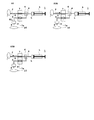
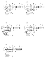
- FIG. 3 is a schematic view for sequentially explaining a series of blood collection operations according to the first embodiment.
- FIG. 3 is a schematic view for sequentially explaining a series of blood collection operations according to the first embodiment. It is the schematic enlarged view which extracted the dripping part of the dripping opening.
- FIG. 1 is a schematic diagram of a blood collection apparatus according to each embodiment.
- Example 1 including Example 2 to be described later, blood will be described as an example of the liquid to be collected, and a blood collection device will be described as an example of the liquid collection device.
- the blood collection apparatus 1 collects blood to be collected in time series.
- a container 10 for collecting the collected blood is installed around the blood collection apparatus 1.
- the radioactivity concentration in the arterial blood of a small animal for example, a mouse or a rat
- centrifugation is performed by rotating the container 10 with a centrifuge (not shown).
- Blood collection apparatus 1 corresponds to the liquid collection apparatus in the present invention
- container 10 corresponds to the container in the present invention.
- the blood collection apparatus 1 is connected to a flow path having a predetermined length (in each embodiment, the first flow path 2, the second flow path 3 and the third flow path 4) and the third flow path 4 among the flow paths.
- a suction / discharge mechanism 5 that pushes and pulls blood to be collected, a connection terminal 6 that branches a plurality of channels (two in each example), and a channel (first channel 2 and second channel in each example)
- a pinch valve 7 that opens and closes the flow path 3) and a dropping port 8 that is connected to the branched flow path (second flow path 3 in each embodiment) and drops the collected blood to be collected. .
- the blood collection device 1 includes a dropping port moving mechanism 9 that moves the dropping port 8 in order to change the position at which the separated and collected blood to be collected is dropped.
- the first flow path 2, the second flow path 3 and the third flow path 4 correspond to the flow paths in the present invention
- the suction / discharge mechanism 5 corresponds to the suction / discharge means in the present invention
- the dropping port 8 It corresponds to the dripping port 8 in the invention.
- the liquid supply source (small animal in each embodiment) side is upstream, and the dripping port 8 side is downstream. Therefore, in this specification, the flow path located upstream from the connection terminal 6 is defined as the first flow path 2, and the flow path located downstream from the connection terminal 6 and upstream from the dropping port 8 is defined as the second flow path 3. And Further, the suction / discharge mechanism 5 is connected to the third flow path 4 when a flow path different from the second flow path 3 for connecting the dropping port 8 is used as the third flow path 4. 5 is constituted.
- a tube having a small cross-sectional area (that is, a thin diameter) is used in order to reduce the amount of blood collected.
- the first flow path 2 and the second flow path 3 have lengths so that the movement of the liquid (blood in each embodiment) can be controlled only by pushing and pulling by the suction / discharge mechanism 5. It is decided in advance. Of course, the length of the third flow path 4 connected to the suction / discharge mechanism 5 may be determined in advance.
- the dripping port 8 connected to the second flow path 3 uses a Shirasu con tube.
- a Shirasukon tube By using a Shirasukon tube, even when blood with high viscosity is collected as in each of the embodiments, the liquid breakage is improved.
- the dripping port 8 is not limited to a Shirascon tube, but may be a tube made of silicon or silicone (other than Shirascon rubber), an injection needle, or a tube surface-treated for a biological sample.
- the suction / discharge mechanism 5 uses a syringe pump.
- a syringe pump for the suction / discharge mechanism 5
- liquid (blood) can be collected by pushing and pulling a few [ ⁇ L] of liquid (blood in each embodiment) with high speed and accuracy.
- the suction / discharge mechanism 5 is a syringe pump capable of accurately pushing and pulling the liquid (blood), and the first flow path 2 and the second flow path 3 are known in advance in length and cross-sectional area. Since the volume can be calculated from the above, the blood flowing in the first flow path 2 or the second flow path 3 is moved by the volume pushed and pulled by the suction / discharge mechanism 5.
- liquid and gas are used as the medium (fluid) by pushing and pulling.
- the gas by pushing and pulling may be air, or any gas that does not react with blood or a heparin solution, as exemplified by rare gases such as helium, neon, and argon, or nitrogen gas.
- the liquid by pushing and pulling is not particularly limited, but it is preferable to use a cleaning liquid typified by a heparin solution used for channel cleaning or blood discharge.
- a low-viscosity liquid such as water or mineral oil is preferable in order to increase blood control accuracy.
- reference numeral BL 1 in FIG. 1 and FIG. 3 to be described later reference numerals BL 1 , BL 2 and BL 3 in FIG. 4 to be described later, and reference numeral BL 2 in FIG. 5 to be described later are blood to be collected.
- the liquid L is illustrated by stippling hatching
- the gas G is illustrated by white painting.
- the first flow path 2, the second flow path 3 and the third flow path 4 are connected by a connection terminal 6.
- the connection terminal 6 uses a block made of PDMS resin (Polydimethylsiloxane) having a minute flow path hole.
- the first flow path 2, the second flow path 3 and the third flow path 4 are connected to the respective holes.
- the connection terminal 6 branches the first flow path 2 into two second flow paths 3 and a third flow path 4.
- a pinch valve 7 for pinching a tube is used as the opening / closing means for opening and closing the flow path.
- the pinch valve 7 applies a pressure from the outside of the tube (see “blocking portion 7a” in FIG. 1 and FIG. 3 and FIG. 4 described later), and the flow path (the first flow path 2 and the second flow path) formed of the tube. 3) is closed, and the flow path (the first flow path 2 and the second flow path 3) made of the tube is opened by releasing the pressure from the outside of the tube.
- the pinch valve 7 is comprised so that when one is opened among two flow paths (1st flow path 2 and 2nd flow path 3) which consist of a tube, the other is closed. . Accordingly, the pinch valve 7 closes the second flow path 3 when the first flow path 2 is opened, and conversely closes the first flow path 2 when the second flow path 3 is opened. Switch.
- the dropping port 8 for dropping the collected blood is positioned on the container 10 for storing the collected blood, and the dropping position is changed by the dropping port moving mechanism 9.
- the dropping port moving mechanism 9 uses an electric slider by a stepping motor, and moves the dropping port 8 forward, backward, left, and right (horizontal direction) by the electric slider.
- the pinch valve 7 so that the distance between the pinch valve 7 and the sampling source (small animal in each embodiment) in the flow path is in the range of 10 [cm] to 20 [cm]. In order to make it easy to connect the pinch valve 7 and prevent the liquid from diffusing, the distance is 15 [cm], which is the center of the range of 10 [cm] to 20 [cm]. It is more preferable to arrange the pinch valve 7 as described above.
- the suction / discharge mechanism 5 is more fluid (liquid L / gas G) than the liquid to be collected (blood BL 1 to BL 3 in FIG. 1 and FIGS. 3, 4 and 5 described later). Fill the side channel. Then, the fluid (liquid L / gas G) filled in the flow path on the side of the suction / discharge mechanism 5 is sucked by the suction / discharge mechanism 5 to suck the liquid (blood BL 1 to BL 3 ) to be collected, The fluid (liquid L / gas G) filled in the flow path on the side of the suction / discharge mechanism 5 is pushed out and stopped at the dropping port 8, and the liquids to be collected (blood BL 1 to BL 3 ) are dropped.
- the fluid is both the liquid L and the gas G
- the liquid L fills the flow path on the suction / discharge mechanism 5 side and the liquid filled in the flow path on the suction / discharge mechanism 5 side.
- Gas G is sandwiched in the flow path between L and the liquid to be collected (blood BL 1 to BL 3 ).
- the liquid L filled in the flow path on the side of the suction / discharge mechanism 5 is sucked by the suction / discharge mechanism 5 to suck the gas G and suck the liquids to be collected (blood BL 1 to BL 3 ).
- the liquid L filled in the flow path on the side of the suction / discharge mechanism 5 is pushed out by the suction / discharge mechanism 5 to push out the gas G and stop at the dropping port 8, and the liquid to be collected (blood BL 1 to BL 3 ) Dripping.
- the volume of the gas G is preferably in the range of 2 [ ⁇ L] to 10 [ ⁇ L].
- the volume is 5 [ ⁇ L] to 6 [ ⁇ L], which is the center of the range of 2 [ ⁇ L] to 10 [ ⁇ L].
- the container 10 has a hydrophilic treatment on the surface to which it is dropped. In addition, when dripping, the container 10 is installed below 1 [cm] away from the dripping port 8.
- FIG. 2 is a flowchart showing a flow of a series of blood collection processes according to each embodiment.
- FIGS. 3 and 4 are schematic diagrams sequentially illustrating a series of blood collection operations according to the first embodiment. It is the schematic enlarged view which extracted the dripping part of the dripping port. 3 and 4, a predetermined amount of blood to be collected (waste liquid) (reference numeral BL 1 ) drawn in the initial state is illustrated by hatching in the upper right diagonal line, and finally collected blood ( The symbol BL 2 ) is shown by hatching in the upper left diagonal line, and the other blood (reference symbol BL 3 ) is shown in black.
- the liquid L is filled in the flow path on the suction / discharge mechanism 5 side, and the gas G is filled in the flow path on the collection source (small animal in each embodiment) side that is the liquid supply source.
- Step S1 in FIG. 3 shows an initial state before blood collection. Since animals gas such as air when pushed back all the blood will die enters the animal body, it is slightly left blood BL 1 outside the body by sucking a predetermined amount of blood BL 1 in order to prevent it. More specifically, the first flow path 2 is opened by the pinch valve 7 and the second flow path 3 is closed, and the suction / discharge mechanism 5 sucks a predetermined amount of blood BL 1 before collection. Set to the initial state. By sucking the predetermined amount of blood BL 1 , the gas G is sandwiched between the liquid L filled in the flow path on the suction / discharge mechanism 5 side and the sucked blood BL 1 .
- Step S2 Collection time? If the blood collection time has not been reached, the reciprocation of step S3 is performed. When the blood collection time is reached, the first suction in step S4 is performed.
- Step S3A in FIG. 3 shows blood aspiration.
- the liquid L filled in the flow path on the side of the suction / discharge mechanism 5 is sucked by the suction / discharge mechanism 5 to suck the gas G and suck blood.
- Step S3B of FIG. 3 shows blood pushback.
- the gas G is pushed back, and the blood is pushed back.
- steps S3A and S3B the liquid L filled in the flow path on the side of the suction / discharge mechanism 5 is pushed and pulled by the suction / discharge mechanism 5 during a waiting time between the collection and the next collection.
- Push and pull G to control the movement of blood to be collected.
- the push-pull of the liquid L filled in the flow path on the suction / discharge mechanism 5 side is repeated, whereby the gas G The push-pull is repeated to control the reciprocation of blood to be collected.
- the first flow path 2 is open and the second flow path 3 is closed.
- the amount to be pushed and pulled is not particularly limited, but may be any amount that can prevent coagulation.
- the amount of blood to be pushed and pulled is 1 [ ⁇ L] to 2 [2]. ⁇ L].
- the suction / discharge mechanism 5 repeats a minute push-pull of 1 [ ⁇ L] to 2 [ ⁇ L] so that the blood continues to move.
- Step S4 First suction At the start of blood collection, the suction and discharge mechanism 5 is pulled to draw blood BL 2 and BL 3 from the animal. More specifically, the pinch valve 7 opens the first flow path 2 and closes the second flow path 3, followed by a predetermined amount of blood BL 1 to be collected drawn in the initial state. Then, the blood BL 2 , BL 3 is further sucked by the suction / discharge mechanism 5 until the blood BL 1 is located at the connection terminal 6. As described in step S3, the blood L is sucked by sucking the liquid L / gas G.
- Step S5 First discharge Since blood BL 2 in the body is to be collected at the time of blood collection, the blood BL 1 that has gone out of the body (that is, a predetermined amount of blood BL 1 to be collected drawn in the initial state) is discarded. Te, to collect the blood BL 2 then to come. For this purpose, the blood BL 1 to be discarded is drawn from the connection terminal 6 to the suction / discharge mechanism 5 side (right side in FIG. 3), and the blocking portion 7 a of the pinch valve 7 is moved from the second flow path 3 to the first flow path 2. Then, the suction / discharge mechanism 5 is pushed to discharge the blood BL 1 from the dripping port 8 via the second flow path 3.
- the pinch valve 7 closes the first flow path 2 and opens the second flow path 3 so that a predetermined amount drawn in the initial state is obtained.
- the blood BL 1 to be collected is pushed back and discharged from the dropping port 8 via the second flow path 3 and discharged.
- the dropping inlet 8 is moved over the container 10 to the outside by dropping inlet moving mechanism 9, discharges the blood BL 1.
- the blood is pushed back by pushing back the liquid L and the gas G.
- step S5 of FIG. 4 the gas G flows into the dropping port 8 connected to the second flow path 3, and the liquid L and the blood BL 2 directly flow at the branch point at the connection terminal 6. Contact.
- the blocking portion 7a of the pinch valve 7 is in the first flow path 2, and the first flow path 2 is closed and the second flow path 3 is opened, the liquid L is mixed into the first flow path 2. It flows without fail to the second flow path 3. Therefore, mixing of the liquid L can be prevented.
- a heparin solution is used for the liquid L, an interface is formed between the heparin solution and blood, so that the mixing of the liquid L can be further prevented.
- the gas L is sucked into the flow path between the liquid L and the blood BL 2 by sucking the liquid L / gas G by the suction / discharge mechanism 5 until the gas G is located at the branch point at the connection terminal 6. It is caught.
- Step S ⁇ b> 6 Second suction
- the dropping port moving mechanism 9 moves the dropping port 8 onto the container 10 to switch the closing portion 7 a of the pinch valve 7 from the first channel 2 to the second channel 3.
- the blood BL 2 is drawn from the connection terminal 6 to the suction / discharge mechanism 5 side (right side in FIG. 3). More specifically, after the first discharge in step S5, the pinch valve 7 opens the first flow path 2 and closes the second flow path 3, and the blood BL 2 to be collected is connected to the connection terminal.
- the blood BL 2 is sucked by the suction / discharge mechanism 5 until it is positioned closer to the suction / discharge mechanism 5 than 6. At this time, the blood BL 3 Following the aspiration of blood BL 2 is also sucked.
- blood is sucked by sucking the liquid L and gas G.
- Step S ⁇ b> 7 The second discharge pinch valve 7 is switched from the second flow path 3 to the first flow path 2, and the suction / discharge mechanism 5 is pressed to drop the blood BL 2 into the container 10 from the dropping port 8. More specifically, after the second suction in step S6, the pinch valve 7 draws out the second suction in step S6 with the first flow path 2 closed and the second flow path 3 opened. The blood BL 2 to be collected is pushed back and discharged from the dropping port 8 through the second flow path 3 and collected. As described in Steps S3 and S5, the blood is pushed back by pushing back the liquid L and the gas G.
- step S5 even when the collected blood BL 2 by the second discharge in the step S7, stop the gas G in dropping inlet 8.
- step S5 in order to create and push out the blood droplets to be collected, it is more preferable to push out 0.5 V, which is half the total volume V, from the dropping port 8 together. Then, after dropping, if 0.5 G of excessively extruded gas G (air in this case) is sucked from the dripping port 8 and returns to the state of step S9 described later, the sucked 0.5V gas G When combined with 0.5V + 0.5V, the total volume returns to V.
- FIG. 5 illustrates the blood BL 2 in black.
- the blood BL 2 has already been cut out and is in a state before being dropped into the container 10.
- the liquid L is in the second flow path 3 and the third flow path 4 (only the second flow path 3 is shown in FIG. 5), which is a flow path on the side of the suction / discharge mechanism 5 (not shown in FIG. 5) including a syringe pump. filled, sandwich the gas G so as not to mix with the blood BL 2.
- the surface of the container 10 to be dropped is subjected to a hydrophilic treatment, when the blood BL 2 comes into contact with the container 10, it is easy to move away from the dropping port 8 and move to the container 10 in FIG. Furthermore, when the flow path of the container 10 has a fine cross-sectional area (for example, the width of the flow path is 0.5 [mm] and the depth of the flow path is 0.2 [mm]), in addition to hydrophilicity, by capillary action, immediately after the blood BL 2 is in contact with the channel inlet, the blood BL 2 is entering into the flow path smoothly.
- a fine cross-sectional area for example, the width of the flow path is 0.5 [mm] and the depth of the flow path is 0.2 [mm]
- the gas L is sucked into the flow path between the liquid L and the blood BL 3 by sucking the liquid L / gas G by the suction / discharge mechanism 5 until the gas G is located at the branch point at the connection terminal 6. It is caught.
- Step S8 Is it collected?
- the process returns to step S2 after pushing back in step S9, and the same processes in steps S2 to S8 are repeated.
- a series of blood collection processing ends.
- Step S9 Push back After dropping, the closing portion 7a of the pinch valve 7 is switched from the first flow path 2 to the second flow path 3, the suction / discharge mechanism 5 is pushed to push the blood BL 3 back to the animal, and the process returns to Step S2. More specifically, after the second discharge in step S7, the blood to be collected by the suction / discharge mechanism 5 in a state where the first flow path 2 is opened by the pinch valve 7 and the second flow path 3 is closed. The BL 3 is pushed back to the animal from which it was collected to the initial state.
- Step S9 the determination of the sampling time in step S2, the reciprocating movement in step S3, the first suction in step S4, the first discharge in step S5, the second suction in step S6, and the second in step S7. Repeat two discharges.
- Steps S3, S5, and S7 the blood is pushed back by pushing back the liquid L and the gas G.
- the liquid L is preferably washed with a heparin solution, water, or mineral oil to clean the inside of the flow path.
- a heparin solution water, or mineral oil to clean the inside of the flow path.
- the effect of washing the liquid (blood) to be collected remaining in the flow path by washing the flow path by moving the liquid L filled in the flow path on the suction / discharge mechanism 5 side in the flow path. Also play.
- the liquid to be collected (blood in each embodiment) is actively pushed and pulled by the suction / discharge mechanism 5.
- Liquid (blood) can be collected regardless of the situation of the (blood) supply source (collection source).
- the blood collection device 1 includes a channel having a predetermined length (in each embodiment, the first channel 2, the second channel 3, and the third channel 4), so that the length is defined in advance.
- the liquid collection device blood collection device 1 in each embodiment
- the liquid collection device can be reduced in size, and can be installed in the vicinity of the liquid collection source (animal in each embodiment).
- the dead volume which indicates an invalid volume
- eliminate the causes of distortion of the concentration waveform such as delay and dispersion.
- a fluid consisting of at least one of the liquid L and the gas G is taken as the liquid to be collected (FIGS. 1, 3, 4 and In FIG. 5, the flow path on the suction / discharge mechanism 5 side is filled with blood BL 1 to BL 3 ). Then, the fluid (liquid L / gas G) filled in the flow path on the suction / discharge mechanism 5 side is sucked by the suction / discharge mechanism 5 to suck the liquid (blood) to be collected, and the suction / discharge mechanism 5 side The fluid (liquid L / gas G) filled in the flow path is pushed out and stopped at the dropping port 8, and the liquid (blood) to be collected is dropped.
- the liquid (blood) to be collected can be accurately dropped from the dropping port 8 by pushing out the fluid (liquid L / gas G) and stopping at the dropping port 8. In this way, by stopping the fluid (liquid L / gas G) at the dripping port 8, it is possible to improve the drainage without leaving the liquid (blood) to be collected at the dripping port 8, and only the necessary amount.
- the liquid (blood) to be collected can be dropped.
- both liquid L and gas G are employed as fluids. That is, in the first embodiment, the fluid is the liquid L and the gas G, and the liquid L fills the flow path on the suction / discharge mechanism 5 side, and the liquid L filled in the flow path on the suction / discharge mechanism 5 side Gas G is sandwiched in the flow path between the liquids to be collected (blood BL 1 to BL 3 ). Then, the liquid L filled in the flow path on the side of the suction / discharge mechanism 5 is sucked by the suction / discharge mechanism 5 to suck the gas G and suck the liquid (blood) to be collected.
- the liquid L filled in the flow channel on the side is pushed out by the suction and discharge mechanism 5 to push out the gas G and stop at the dropping port 8 to drop the liquid (blood) to be collected. If the liquid L is packed in the flow path, and the gas G is sandwiched and pushed from the liquid (blood) to be collected, the volume of the gas G compressed or expanded by the push / pull by the suction / discharge mechanism 5 is reduced. The liquid (blood) to be collected can be moved with high accuracy.
- the liquid (blood) to be collected can be stopped immediately before a desired position (for example, a position where blood is supplied by pushing back in step S3) using a flow path having a predetermined length, and further, gas By extruding G and stopping at the dropping port 8, the liquid (blood) to be collected can be dropped accurately from the dropping port 8.
- a desired position for example, a position where blood is supplied by pushing back in step S3
- gas By extruding G and stopping at the dropping port 8
- the liquid (blood) to be collected can be dropped accurately from the dropping port 8.
- the liquid (blood) to be collected can be improved without remaining at the dropping port 8, and the liquid (blood) to be collected at the dropping destination.
- the liquid (blood) which collects only a required quantity can be dripped, without dripping and mixing other than.
- the former liquid L and the latter (collection target) liquid (blood) ) can be prevented from contacting and mixing, and the liquid (blood) to be collected can also be prevented from thinning due to mixing.
- the container 10 as the dropping destination has a hydrophilic surface, and a liquid droplet (blood) dropped from the dropping port 8 is brought into contact with the container 10 to drop the liquid (blood) to be collected. It is preferable to do this. Since the dropped liquid (blood) is a very small amount (less than 1 [ ⁇ L] that reciprocates in step S3), even if the liquid L or gas G is stopped at the dropping port 8, a droplet is formed. It may be difficult to separate and drop from the dropping port 8. In order to separate the liquid droplets, an extra fluid of the liquid L or the gas G is sent. In particular, when the gas G is sent as in the first embodiment, there is a possibility that the liquid (blood) to be collected is foamed. is there.
- the dropping port 8 side of the flow channel (here, the second flow channel 3) is formed of a tube, and the liquid (blood) to be collected is dropped from the dropping port 8 of the flow channel formed by the tube.
- a tube it is easy to run out of the liquid.
- the liquid can be further cut out.
- a tube made of Shirasukon which is a kind of silicone (Shirasukon tube)
- the tube is made of Shirasukon rubber, and the liquid (blood) to be collected is dropped from the dropping port 8 of the flow path formed of the tube made of Shirasukon rubber (ie, Shirasukon tube).
- the liquid collecting apparatus that performs the liquid dropping method is a blood collecting apparatus, that is, the blood collecting apparatus 1.
- Embodiment 2 of the present invention will be described with reference to the drawings.
- both liquid and gas are employed as the fluid.
- only one of the liquid and the gas is employed as the fluid. 3 and FIG. 4 are used.
- the gas G is not particularly limited and may be air as in the first embodiment, or reacts with blood or a heparin solution, as exemplified by rare gases such as helium, neon, and argon, or nitrogen gas. Any gas that does not work.
- the liquid L is not particularly limited, and is a heparin solution, water, or mineral oil as in the first embodiment.
- steps S1 to S9 Since the flowchart of steps S1 to S9 is the same as that of the first embodiment, the description thereof is omitted.
- the gas G When the fluid is gas G, the gas G is filled in the flow path on the suction / discharge mechanism 5 side with respect to the liquid (blood) to be collected, and the gas G filled in the flow path on the suction / discharge mechanism 5 side is sucked.
- the liquid (blood) to be collected is sucked by the discharge mechanism 5, the gas G filled in the flow path on the suction / discharge mechanism 5 side is pushed out and stopped at the dropping port 8, and the liquid to be collected (Blood) is dropped. If the gas L is packed in the flow path and the liquid (blood) to be collected is pushed and pulled by the gas G, the liquid (blood) to be collected can be accurately guided to the dripping port 8, and the gas G is further pushed out.
- the liquid (blood) to be collected can be dropped from the dropping port 8 with high accuracy.
- the liquid (blood) to be collected can be improved without leaving the liquid (blood) to be collected at the dropping port 8, and the liquid (blood) to be collected only in a necessary amount. Can be dripped.
- only the gas G is used as a medium without using other liquids, it is possible to prevent the liquid to be collected (blood) and other liquids from coming into contact with each other and mixing them. It is also possible to prevent the liquid (blood) from being diluted.
- the gas G is filled in the flow path on the suction / discharge mechanism 5 side than the liquid (blood) to be collected, and the liquid L filled in the flow path on the suction / discharge mechanism 5 side is sucked.
- the liquid (blood) to be collected is sucked by the discharge mechanism 5, the liquid L filled in the flow path on the suction / discharge mechanism 5 side is pushed out and stopped at the dropping port 8, and the liquid to be collected (Blood) is dropped.
- the liquid (blood) to be collected can be accurately guided to the dropping port 8; Furthermore, the liquid (blood) to be collected can be accurately dropped from the dripping port 8 by extruding the liquid L (which serves as a medium) and stopping at the dripping port 8.
- the liquid L which becomes a medium
- the medium In addition to the liquid (blood) to be measured, the medium and There is a risk that the liquid L will be dropped and mixed. Therefore, if the liquid L serving as a medium is pushed out and stopped to just before the dropping port 8, the liquid (blood) to be collected is not dropped but left in the flow path and stopped at the dropping port 8. Only (blood) can be dripped.
- the present invention is not limited to the above embodiment, and can be modified as follows.
- blood has been described as an example of the collection target liquid.
- the liquid is not limited to blood but may be a physiological fluid other than blood (for example, a fluid containing lymph or protein), a fluid containing a fluorescent agent, a mixed solution used in an analyzer, or the like.
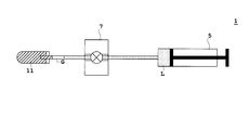
- the blood collection device 1 is shown in FIG. 1, but is not limited to the structure shown in FIG. 1.
- a flow path having a predetermined length a suction discharge means (suction discharge mechanism) connected to the flow path to push and pull the liquid, and a liquid to be collected that is connected to the flow path and separated and collected (in each embodiment)
- Any liquid sampling device provided with a dropping port for dropping blood) can be applied to the liquid sampling device as shown in FIG. 6 or FIG.
- the blood is accommodated in a state in which an anticoagulant for preventing the occurrence of blood coagulation is applied to the container 11 or as described above.
- the liquid to be collected contains a liquid other than blood in the container 11, the liquid to be collected (in the upper right diagonal line) with the first flow path 2 inserted into the container 11.
- the liquid L filled in the flow path on the side of the suction / discharge mechanism 5 is pushed out by the suction / discharge mechanism 5 to push out the gas G and stop at the dropping port 8 to drop the liquid to be collected.
- the medium (fluid) by pushing and pulling may be only the liquid L or only the gas G.
- a liquid to be collected (shown by hatching in the upper right oblique line) is sucked in a state where a single flow path (tube) that does not branch is inserted into the container 11, and a suction / discharge mechanism
- the liquid L filled in the flow path on the 5th side may be pushed out by the suction / discharge mechanism 5 to push out the gas G and stop at the dropping port 8, and the liquid to be collected may be dropped.
- the flow path is removed from the container 11, discharged from the dropping port of the flow path, and dropped into the collection container (not shown in FIG. 7).
- the flow path serves as both a flow path for sucking liquid and a flow path for dropping.
- an opening / closing means such as the pinch valve 7 is not necessarily required.
- the medium (fluid) by pushing and pulling may be only the liquid L or only the gas G.
- the flow path is a tube, but may be a groove provided in a substrate or the like, for example.
- the opening and closing means for opening and closing the flow path is opened and closed by using a valve of a type that allows liquid to pass inside other than the pinch valve.
- the opening / closing means for opening and closing the flow path is a pinch valve.
- a valve that allows liquid to pass inside other than the pinch valve may be.
- the first flow path and the second flow path are formed by the Shirasucon tube only at the portion pinched by the pinch valve, but it is not limited to the Shirasucon.
- Each flow path may be formed of a tube made of a rubber material having softness and resilience such as silicone, Tygon, and polyurethane. Further, the material may be changed for only the portion to be pinched, and the same material may be used for the first flow path and the second flow path, or the entire first to third flow paths.
- the entire flow path is formed of a tube.
- at least the dropping port side of the flow path is formed of a tube.
- the channel is formed by a groove. And you may form only the dripping opening
- the surface of the container to which the solution is dropped is hydrophilic, but the container does not necessarily have a hydrophilic surface when there is no fear of foaming.
Landscapes
- Health & Medical Sciences (AREA)
- Life Sciences & Earth Sciences (AREA)
- Engineering & Computer Science (AREA)
- Heart & Thoracic Surgery (AREA)
- Molecular Biology (AREA)
- Pathology (AREA)
- Physics & Mathematics (AREA)
- Biomedical Technology (AREA)
- Hematology (AREA)
- Medical Informatics (AREA)
- Biophysics (AREA)
- Surgery (AREA)
- Animal Behavior & Ethology (AREA)
- General Health & Medical Sciences (AREA)
- Public Health (AREA)
- Veterinary Medicine (AREA)
- Manufacturing & Machinery (AREA)
- Sampling And Sample Adjustment (AREA)
Description
この発明は、液体採取装置における液体滴下方法に関する。
液体採取装置として、血液を採取する、すなわち採血する採血装置を例にとって説明する。採血装置は、核医学診断(例えば、PET(Positron Emission Tomography)など)における定量解析で用いられる。核医学診断において、神経受容体の濃度や腫瘍の代謝などの生体機能情報を定量解析するためには、動脈血の血漿中の薬剤濃度、すなわち放射能濃度の時間変化の測定が必要となる。血中放射能濃度を測定するための自動採血装置として以下の方式が採用されている(例えば、特許文献1、2、非特許文献1~3参照)。これらの装置は、小動物(例えばマウスやラットなど)の動脈血中の放射能濃度の測定に用いられている。
(特許文献1)
マウス血圧にて自出された動脈血を、マイクロチップ上に導く方式である。
マウス血圧にて自出された動脈血を、マイクロチップ上に導く方式である。
(特許文献2)
特許文献2での自動採血装置では、シリンジポンプで動物から血液が引き出され、その血液が、流路内を満たす洗浄液と接触しないように空気層を挟んで容器に押し出される。最小採血量10[μL]、最短10分間隔の採血が可能となっている。本発明に係る自動採血装置とは用途が異なり、高速かつ微量の自動採血を行うことを目的としていない。
特許文献2での自動採血装置では、シリンジポンプで動物から血液が引き出され、その血液が、流路内を満たす洗浄液と接触しないように空気層を挟んで容器に押し出される。最小採血量10[μL]、最短10分間隔の採血が可能となっている。本発明に係る自動採血装置とは用途が異なり、高速かつ微量の自動採血を行うことを目的としていない。
(特許文献3)
特許文献3では、検体試料の吸い込みと滴下とを兼ねた給排手段を検体に浸けてピストンで定量採取し、給排手段がスライドガラス上に接して試料を滴下し、さらにスライドガラスを横移動させて試料を展開する。
特許文献3では、検体試料の吸い込みと滴下とを兼ねた給排手段を検体に浸けてピストンで定量採取し、給排手段がスライドガラス上に接して試料を滴下し、さらにスライドガラスを横移動させて試料を展開する。
しかしながら、それぞれの方式については以下の課題がある。
(特許文献1)
動物の血圧に頼る採血方式であるので、動物の状態に左右されやすく血圧が低下したときに採血することができなくなることも考えられる。
動物の血圧に頼る採血方式であるので、動物の状態に左右されやすく血圧が低下したときに採血することができなくなることも考えられる。
(特許文献2)
上述したように、最小採血量10[μL]、最短10分間隔の採血であり、1 [μL]~4[μL]の極微量の血液を数秒で滴下することに対応していない。
上述したように、最小採血量10[μL]、最短10分間隔の採血であり、1 [μL]~4[μL]の極微量の血液を数秒で滴下することに対応していない。
(特許文献3)
上述したように、給排手段がスライドガラス上に接して液体を滴下する。本出願人や本発明者等が発明しようとしている自動採血装置は、時系列に採血する装置で複数回の採血がある。したがって、滴下口を下げて容器に接触させ、滴下が終了すると滴下口を上げて容器から離すという動作を滴下の度に繰り返す必要が発生する。そのようにした場合には、滴下口の上下動作により1回の採血動作にかかる時間が長くなり、また滴下口あるいは容器の上下機構が必要になって装置が大掛かりになる。さらに、特許文献3の段落番号「0025」にも記載されているように、標本として必要な量が5[μL]の場合には50[μL]から100[μL]の血液が必要となり、実際には多量の血液が必要である。したがって、動物から直接的に血液を採取する場合には動物が死ぬ恐れがある。また、容器に血液を予め収容するので、血液凝固を防止するためにはヘパリン(heparin)等の凝固防止剤が必要で、血液が薄まるという問題がある。
上述したように、給排手段がスライドガラス上に接して液体を滴下する。本出願人や本発明者等が発明しようとしている自動採血装置は、時系列に採血する装置で複数回の採血がある。したがって、滴下口を下げて容器に接触させ、滴下が終了すると滴下口を上げて容器から離すという動作を滴下の度に繰り返す必要が発生する。そのようにした場合には、滴下口の上下動作により1回の採血動作にかかる時間が長くなり、また滴下口あるいは容器の上下機構が必要になって装置が大掛かりになる。さらに、特許文献3の段落番号「0025」にも記載されているように、標本として必要な量が5[μL]の場合には50[μL]から100[μL]の血液が必要となり、実際には多量の血液が必要である。したがって、動物から直接的に血液を採取する場合には動物が死ぬ恐れがある。また、容器に血液を予め収容するので、血液凝固を防止するためにはヘパリン(heparin)等の凝固防止剤が必要で、血液が薄まるという問題がある。
この発明は、このような事情に鑑みてなされたものであって、必要な量のみ採取する液体を滴下することができる液体滴下方法を提供することを目的とする。
この発明は、このような目的を達成するために、次のような構成をとる。
すなわち、この発明に係る液体滴下方法は、所定の長さを有する流路と、その流路に接続し液体を押し引きする吸引吐出手段と、前記流路に接続され、分離採取された採取対象の液体を滴下する滴下口とを備えた液体採取装置における液体滴下方法であって、液体,気体の少なくともいずれか一方からなる流体を採取対象の液体よりも前記吸引吐出手段側の前記流路に満たし、吸引吐出手段側の流路に満たされた前記流体を吸引吐出手段により吸引することにより、採取対象の液体を吸引して、吸引吐出手段側の流路に満たされた当該流体を押し出して前記滴下口で止めて、採取対象の液体を滴下することを特徴とするものである。
すなわち、この発明に係る液体滴下方法は、所定の長さを有する流路と、その流路に接続し液体を押し引きする吸引吐出手段と、前記流路に接続され、分離採取された採取対象の液体を滴下する滴下口とを備えた液体採取装置における液体滴下方法であって、液体,気体の少なくともいずれか一方からなる流体を採取対象の液体よりも前記吸引吐出手段側の前記流路に満たし、吸引吐出手段側の流路に満たされた前記流体を吸引吐出手段により吸引することにより、採取対象の液体を吸引して、吸引吐出手段側の流路に満たされた当該流体を押し出して前記滴下口で止めて、採取対象の液体を滴下することを特徴とするものである。
この発明に係る液体滴下方法によれば、液体採取装置において、吸引吐出手段により採取対象の液体を能動的に押し引きすることで液体の供給元(採取元)の状況に依らず液体を採取することができる。例えば、動物の場合で採取対象の液体が血液の場合には、動物の生理状態によって血圧が低下しても採血することができる。その結果、たとえ動物の血圧が低下した状況でも、液体を採取することができる。また、液体採取装置において、所定の長さを有する流路を備えることで、長さが予め規定され体積が既知の流路を有するので、採取対象の液体の長さや採取量を体積測定手段(例えば、光学的な測定手段)で測定することなく、規定の体積量を採取することができる。このように測定手段が不要となることで液体採取装置を小型化することができ、液体の採取元(例えば動物)の近傍に設置することができる。この結果、デッドボリューム(無効となる体積を指す)の減少、delay, dispersionといった濃度波形の歪みの要因の排除を実現している。
このような液体採取装置を用いて液体を滴下して採取する際に、液体,気体の少なくともいずれか一方からなる流体を採取対象の液体よりも吸引吐出手段側の流路に満たす。そして、吸引吐出手段側の流路に満たされた流体を吸引吐出手段により吸引することにより、採取対象の液体を吸引して、吸引吐出手段側の流路に満たされた当該流体を押し出して滴下口で止めて、採取対象の液体を滴下する。流体を流路に詰めて、採取対象の液体を流体により押し引きすれば、採取対象の液体を滴下口にまで精度良く導くことができ、さらには流体を押し出して滴下口で止めることで、採取対象の液体を滴下口から精度良く滴下することができる。このように、流体を滴下口で止めることで、滴下口で採取対象の液体が残留することなく液切れを向上させることができ、必要な量のみ採取する液体を滴下することができる。
流体としては、下記のように液体および気体の両方、気体のみ、あるいは液体のみが挙げられる。
すなわち、最初の一例は、流体は液体および気体であって、当該液体を吸引吐出手段側の流路に満たし、吸引吐出手段側の流路に満たされた当該液体と採取対象の液体との間に気体を流路内に挟み込む。そして、吸引吐出手段側の流路に満たされた当該液体を吸引吐出手段により吸引することにより気体を吸引して、採取対象の液体を吸引して、吸引吐出手段側の流路に満たされた当該液体を吸引吐出手段により押し出すことにより気体を押し出して滴下口で止めて、採取対象の液体を滴下することである。液体を流路に詰めて、採取対象の液体との間に気体を挟み込んで押し引きすれば、吸引吐出手段による押し引きによって圧縮または膨張される気体の体積が減るので採取対象の液体を精度良く動かすことができる。よって、所定の長さを有する流路を用いて所望の位置の直前に採取対象の液体を止めることができ、さらには気体を押し出して滴下口で止めることで、採取対象の液体を滴下口から精度良く滴下することができる。このように、気体を滴下口で止めることで、滴下口で採取対象の液体が残留することなく液切れを向上させることができ、滴下先で採取対象の液体以外が滴下されて混じることなく必要な量のみ採取する液体を滴下することができる。さらに、吸引吐出手段側の流路に満たされた液体と採取対象の液体との間に気体を挟み込むことで、前者の液体と後者の(採取対象の)液体とが接触して混合するのを防止することができ、混合により採取対象の液体が薄まることも防止することができる。
すなわち、最初の一例は、流体は液体および気体であって、当該液体を吸引吐出手段側の流路に満たし、吸引吐出手段側の流路に満たされた当該液体と採取対象の液体との間に気体を流路内に挟み込む。そして、吸引吐出手段側の流路に満たされた当該液体を吸引吐出手段により吸引することにより気体を吸引して、採取対象の液体を吸引して、吸引吐出手段側の流路に満たされた当該液体を吸引吐出手段により押し出すことにより気体を押し出して滴下口で止めて、採取対象の液体を滴下することである。液体を流路に詰めて、採取対象の液体との間に気体を挟み込んで押し引きすれば、吸引吐出手段による押し引きによって圧縮または膨張される気体の体積が減るので採取対象の液体を精度良く動かすことができる。よって、所定の長さを有する流路を用いて所望の位置の直前に採取対象の液体を止めることができ、さらには気体を押し出して滴下口で止めることで、採取対象の液体を滴下口から精度良く滴下することができる。このように、気体を滴下口で止めることで、滴下口で採取対象の液体が残留することなく液切れを向上させることができ、滴下先で採取対象の液体以外が滴下されて混じることなく必要な量のみ採取する液体を滴下することができる。さらに、吸引吐出手段側の流路に満たされた液体と採取対象の液体との間に気体を挟み込むことで、前者の液体と後者の(採取対象の)液体とが接触して混合するのを防止することができ、混合により採取対象の液体が薄まることも防止することができる。
また、次の一例は、流体は気体であって、当該気体を採取対象の液体よりも吸引吐出手段側の流路に満たし、吸引吐出手段側の流路に満たされた当該気体を吸引吐出手段により吸引することにより、採取対象の液体を吸引して、吸引吐出手段側の流路に満たされた当該気体を押し出して滴下口で止めて、採取対象の液体を滴下することである。気体を流路に詰めて、採取対象の液体を気体により押し引きすれば、採取対象の液体を滴下口にまで精度良く導くことができ、さらに気体を押し出して滴下口で止めることで、採取対象の液体を滴下口から精度良く滴下することができる。このように、気体を滴下口で止めることで、滴下口で採取対象の液体が残留することなく液切れを向上させることができ、必要な量のみ採取する液体を滴下することができる。また、媒体として他の液体を用いずに気体のみを用いているので、採取対象の液体と他の液体とが接触して混合するのを防止することができ、混合により採取対象の液体が薄まることも防止することができる。
最後の一例は、流体は液体であって、当該液体を採取対象の液体よりも吸引吐出手段側の流路に満たし、吸引吐出手段側の流路に満たされた当該液体を吸引吐出手段により吸引することにより、採取対象の液体を吸引して、吸引吐出手段側の流路に満たされた当該液体を押し出して滴下口で止めて、採取対象の液体を滴下することである。液体を流路に詰めて、採取対象の液体を(媒体となる)液体により押し引きすれば、採取対象の液体を滴下口にまで精度良く導くことができ、さらに(媒体となる)液体を押し出して滴下口で止めることで、採取対象の液体を滴下口から精度良く滴下することができる。ただし、最初の一例や次の一例と相違して、押し出しの際に(媒体となる)液体を滴下口にまで押し出すと測定対象の液体の他に媒体となる液体が滴下して混合される恐れがある。そこで、媒体となる液体を滴下口寸前にまで押し出して止めることで、採取対象の液体を全て滴下せずに流路内に残して滴下口で止めれば、採取対象の液体のみを滴下することができる。
この発明に係る液体制御方法において、滴下先の容器は表面が親水性であり、滴下口から滴下された液体からなる液滴を容器に接触させて、採取対象の液体を滴下するのが好ましい。滴下される液体は微量であるので、液体や気体の流体を滴下口で止めたとしても、液滴を作って滴下口から切り離して落下させるのが困難な場合がある。液滴を切り離すためには液体や気体の流体を余分に送ることになり、特に気体を送り込む場合には採取対象の液体が発泡する可能性がある。そこで、表面が親水性の容器に、滴下口から滴下された液体からなる液滴を接触させると接した瞬間に、親水性の容器表面に引っ張られて液滴が容器側に移らせることで、余分な液体や気体の流体を送り出さずに滴下することができる。その結果、液体が発泡することなく容器に確実に、かつ円滑に滴下することができる。また、液体の発泡を防止するための滴下ガイド等が不要になり液体採取装置が小型化になるという効果をも奏する。
また、少なくとも流路の滴下口側をチューブで形成し、そのチューブで形成された流路の滴下口から採取対象の液体を滴下する。チューブの場合には液切れし易く、特に、生体適合性の高いシリコンまたはシリコーンからなるチューブの場合には、液切れをより一層向上させることができる。また、シリコーンの一種であるシラスコン(登録商標)からなるチューブ(シラスコンチューブ)の場合には、液切れをより一層向上させることができる。そのためには、チューブをシラスコンゴムで形成し、シラスコンゴムからなるチューブ(すなわちシラスコンチューブ)で形成された流路の滴下口から採取対象の液体を滴下する。
上述したこれらの発明に係る液体滴下方法において、採取対象の液体の一例は血液である。この場合には、液体滴下方法を行う液体採取装置は採血するための装置(採血装置)となる。なお、採取対象の液体であれば、血液に限定されずに、血液以外の生理液(例えばリンパ液やタンパクが含まれた液など)や、蛍光剤が含まれた液体や、分析装置に用いられる混合液などであってもよい。
この発明に係る液体滴下方法によれば、流体を滴下口で止めることで、滴下口で採取対象の液体が残留することなく液切れを向上させることができ、必要な量のみ採取する液体を滴下することができる。
以下、図面を参照してこの発明の実施例1を説明する。図1は、各実施例に係る採血装置の概略図である。後述する実施例2も含めて、本実施例1では、採取対象の液体として血液を例に採って説明するとともに、液体採取装置として採血装置を例に採って説明する。
図1に示すように、各実施例に係る採血装置1は、採取対象の血液を時系列に分離して採取する。また、採血装置1の周辺には、採取された血液を溜める容器10を設置している。後述する実施例2も含めて、本実施例1では、小動物(例えばマウスやラットなど)の動脈血中の放射能濃度を測定する。また、容器10を遠心機(図示省略)で回転させることで遠心分離を行う。各実施例では血液の遠心分離を行うので、血漿分離を行い、血漿分離された血漿および血球に含まれている放射線をそれぞれ測定する。採血装置1は、この発明における液体採取装置に相当し、容器10は、この発明における容器に相当する。
採血装置1は、所定の長さを有する流路(各実施例では第1流路2,第2流路3および第3流路4)と、その流路のうち第3流路4に接続し採取対象の血液を押し引きする吸引吐出機構5と、流路を複数(各実施例では2つ)に分岐させる接続端子6と、流路(各実施例では第1流路2および第2流路3)を開閉するピンチバルブ7と、分岐した流路(各実施例では第2流路3)に接続され、分離採取された採取対象の血液を滴下する滴下口8とを備えている。その他に、採血装置1は、分離採取された採取対象の血液を滴下する位置を変えるために滴下口8を移動させる滴下口移動機構9を備えている。第1流路2,第2流路3および第3流路4は、この発明における流路に相当し、吸引吐出機構5は、この発明における吸引吐出手段に相当し、滴下口8は、この発明における滴下口8に相当する。
血液を押し戻す場合を除いて血液の採取の流れを基準にすると、液体の供給元である採取元(各実施例では小動物)側が上流となり、滴下口8側が下流となる。よって、本明細書では、接続端子6よりも上流に位置する流路を第1流路2とし、接続端子6よりも下流で滴下口8よりも上流に位置する流路を第2流路3とする。また、吸引吐出機構5は、滴下口8を接続する第2流路3とは別の流路を第3流路4としたときに当該第3流路4に接続するように、吸引吐出機構5を構成している。
流路(第1流路2,第2流路3および第3流路4)は、採血量を減らすために断面積が小さい(すなわち細い径の)チューブを使用している。各実施例では、内径0.28[mm]のポリエチレンチューブと、ピンチバルブ7でピンチされる部分だけポリエチレンチューブよりも柔らかく復元力のある内径0.5[mm]のシリコーンの一種であるシラスコンからなるチューブ(シラスコンチューブ)とをそれぞれ使用している。また、流路のうち、第1流路2および第2流路3は、吸引吐出機構5による押し引きだけで液体(各実施例では血液)の動きの制御を可能とするように長さが予め決められている。もちろん、吸引吐出機構5に接続された第3流路4についても、長さを予め決めてもよい。
また、第2流路3に接続された滴下口8も、シラスコンチューブを使用している。シラスコンチューブを使用することで、各実施例のように粘性の高い血液を採取する場合であっても液切れを向上させる。なお、滴下口8については、シラスコンチューブに限定されず、シリコンまたは(シラスコンゴム以外の)シリコーンからなるチューブ、注射針、あるいは生体試料用に表面処理されたチューブであってもよい。
吸引吐出機構5は、シリンジポンプを使用する。吸引吐出機構5にシリンジポンプを使うことで数[μL]の液体(各実施例では血液)を高速かつ精度良く押し引きして液体(血液)を採取することができる。また、動物の生理状態によって血圧が変動しても、その影響を受けずに安定して採血することができる。このように、吸引吐出機構5は、精度良く液体(血液)の押し引きが可能なシリンジポンプであり、第1流路2および第2流路3は、予め長さおよび断面積がわかっていることから体積を計算することができるので、吸引吐出機構5で押し引きした体積の分だけ第1流路2または第2流路3の内部を流れる血液を動かす。
なお、押し引きによる媒体(流体)として本実施例1では液体および気体を採用する。また、押し引きによる気体については、空気であってもよいし、ヘリウムやネオンやアルゴンなどの希ガス、あるいは窒素ガスに例示されるように、血液やヘパリン溶液と反応しないガスであれば良い。押し引きによる液体については、特に限定されないが、流路洗浄や血液排出用に使用するヘパリン溶液などに代表される洗浄液を用いるのが好ましい。その他にも、血液の制御精度を上げるために水やミネラルオイルのような低粘性の液体が好ましい。
なお、図1や後述する図3、図4および図5中の符号Gは気体であり、図1や後述する図3、図4および図5の符号Lは採取対象の血液とは異なる液体であり、図1や後述する図3中の符号BL1や後述する図4中の符号BL1,BL2およびBL3や後述する図5中の符号BL2は採取対象の血液である。また、図1や後述する図3、図4および図5では、液体Lを点描のハッチングで図示するとともに、気体Gを白塗りで図示する。
第1流路2,第2流路3および第3流路4は接続端子6により接続されている。各実施例では、接続端子6は、微小な流路の穴を有するPDMS樹脂(Polydimethylsiloxane)からなるブロックを使用している。各々の当該穴に第1流路2,第2流路3および第3流路4をそれぞれ接続する。また、上流側を基準にすると、接続端子6は、第1流路2を2つの第2流路3および第3流路4に分岐させることになる。
各実施例では、流路を開閉する開閉手段は、チューブをピンチするピンチバルブ7を使用している。ピンチバルブ7は、チューブの外側から圧力をかける(図1や後述する図3および図4の「閉塞部7a」を参照)ことでチューブからなる流路(第1流路2および第2流路3)を閉じて、チューブの外側からの圧力を開放することでチューブからなる流路(第1流路2および第2流路3)を開けるように構成されている。また、各実施例では、ピンチバルブ7は、チューブからなる2つの流路(第1流路2および第2流路3)のうち、一方を開けたときに他方を閉じるように構成されている。したがって、ピンチバルブ7は、第1流路2を開けたときに第2流路3を閉じて、逆に第2流路3を開けたときに第1流路2を閉じるように閉塞部7aを切り替える。
採取された血液を滴下する滴下口8は、採取された血液を溜める容器10の上に位置し、滴下する位置を滴下口移動機構9により変える。各実施例では、滴下口移動機構9は、ステッピングモータによる電動スライダを使用し、電動スライダにより滴下口8を前後左右(水平方向)に移動させる。
また、ピンチバルブ7と流路における採取元(各実施例では小動物)との間の距離が10[cm]~20[cm]の範囲になるようにピンチバルブ7を配設するのが好ましい。ピンチバルブ7の接続作業を容易にすること、液体の拡散を防止することを両立させるためには、当該距離が10[cm]~20[cm]の範囲の中央である15[cm]になるようにピンチバルブ7を配設するのがより好ましい。
また、図1に示すように、流体(液体L・気体G)を採取対象の液体(図1や後述する図3、図4および図5では血液BL1~BL3)よりも吸引吐出機構5側の流路に満たす。そして、吸引吐出機構5側の流路に満たされた流体(液体L・気体G)を吸引吐出機構5により吸引することにより、採取対象の液体(血液BL1~BL3)を吸引して、吸引吐出機構5側の流路に満たされた当該流体(液体L・気体G)を押し出して滴下口8で止めて、採取対象の液体(血液BL1~BL3)を滴下する。
特に、本実施例1では、流体は液体Lおよび気体Gの両方であって、当該液体Lを吸引吐出機構5側の流路に満たし、吸引吐出機構5側の流路に満たされた当該液体Lと採取対象の液体(血液BL1~BL3)との間に気体Gを流路内に挟み込む。そして、吸引吐出機構5側の流路に満たされた当該液体Lを吸引吐出機構5により吸引することにより気体Gを吸引して、採取対象の液体(血液BL1~BL3)を吸引して、吸引吐出機構5側の流路に満たされた当該液体Lを吸引吐出機構5により押し出すことにより気体Gを押し出して滴下口8で止めて、採取対象の液体(血液BL1~BL3)を滴下する。
気体Gの体積は、2[μL]~10[μL]の範囲であるのが好ましい。吸引吐出手段側の流路に満たされた液体Lと採取対象の液体(各実施例では血液)との接触を防止すること、採取対象の液体(血液)の動きを制御する精度を保つことを両立させるためには、当該体積が2[μL]~10[μL]の範囲の中央である5[μL]~6[μL]であるのがより好ましい。
容器10は、滴下される側の表面が親水処理されている。なお、滴下する際には、滴下口8から1[cm]程離れた下方に容器10を設置する。
次に、一連の採血処理について、図2、図3、図4および図5を参照して説明する。図2は、各実施例に係る一連の採血処理の流れを示したフローチャートであり、図3および図4は、実施例1に係る一連の採血動作を順に説明した概略図であり、図5は、滴下口の滴下部分を抜き出した概略拡大図である。また、図3および図4では、初期状態で引き出された所定量の採取対象の血液(廃液)(符号はBL1)を、右上斜線のハッチングで図示するとともに、最終的に採取される血液(符号はBL2)を、左上斜線のハッチングで図示し、それ以外の血液(符号はBL3)を黒塗りで図示する。なお、ステップS1の初期状態設定の段階で、液体Lを吸引吐出機構5側の流路に満たし、気体Gを液体の供給元である採取元(各実施例では小動物)側の流路に満たした状態に設定する。
(ステップS1)初期状態設定
図3のステップS1は採血前の初期状態を示す。動物に血液を全て押し戻すと空気などの気体が動物体内に入って死んでしまうので、それを防止するために血液BL1を所定量だけ吸引することで血液BL1を体外に少し残している。より具体的に説明すると、ピンチバルブ7により、第1流路2を開けて、第2流路3を閉じた状態で、吸引吐出機構5により所定量の血液BL1を吸引することで採取前の初期状態と設定する。この所定量の血液BL1の吸引により、吸引吐出機構5側の流路に満たされた液体Lと吸引された血液BL1との間に気体Gが流路内に挟み込まれる。
図3のステップS1は採血前の初期状態を示す。動物に血液を全て押し戻すと空気などの気体が動物体内に入って死んでしまうので、それを防止するために血液BL1を所定量だけ吸引することで血液BL1を体外に少し残している。より具体的に説明すると、ピンチバルブ7により、第1流路2を開けて、第2流路3を閉じた状態で、吸引吐出機構5により所定量の血液BL1を吸引することで採取前の初期状態と設定する。この所定量の血液BL1の吸引により、吸引吐出機構5側の流路に満たされた液体Lと吸引された血液BL1との間に気体Gが流路内に挟み込まれる。
(ステップS2)採取時刻?
採血時刻に到達していない場合には、ステップS3の往復移動を行う。採血時刻に到達した場合には、ステップS4の第1吸引を行う。
採血時刻に到達していない場合には、ステップS3の往復移動を行う。採血時刻に到達した場合には、ステップS4の第1吸引を行う。
(ステップS3)往復移動
図3のステップS3Aは血液の吸引を示す。吸引吐出機構5側の流路に満たされた液体Lを吸引吐出機構5により吸引することにより気体Gを吸引し、血液を吸引する。図3のステップS3Bは血液の押し戻しを示す。吸引吐出機構5側の流路に満たされた液体Lを吸引吐出機構5により押し戻すことにより気体Gを押し戻し、血液を押し戻す。このステップS3AおよびS3Bを行うことで、採取と次の採取との間である待機時間に吸引吐出機構5側の流路に満たされた当該液体Lを吸引吐出機構5により押し引きすることにより気体Gを押し引きして、採取対象の血液を移動制御する。ステップS2に戻り、次の採血時刻に達するまで、ステップS2およびS3の処理を繰り返して行うことで、吸引吐出機構5側の流路に満たされた液体Lの押し引きを繰り返すことにより気体Gの押し引きを繰り返し、採取対象の血液の往復移動を制御する。
図3のステップS3Aは血液の吸引を示す。吸引吐出機構5側の流路に満たされた液体Lを吸引吐出機構5により吸引することにより気体Gを吸引し、血液を吸引する。図3のステップS3Bは血液の押し戻しを示す。吸引吐出機構5側の流路に満たされた液体Lを吸引吐出機構5により押し戻すことにより気体Gを押し戻し、血液を押し戻す。このステップS3AおよびS3Bを行うことで、採取と次の採取との間である待機時間に吸引吐出機構5側の流路に満たされた当該液体Lを吸引吐出機構5により押し引きすることにより気体Gを押し引きして、採取対象の血液を移動制御する。ステップS2に戻り、次の採血時刻に達するまで、ステップS2およびS3の処理を繰り返して行うことで、吸引吐出機構5側の流路に満たされた液体Lの押し引きを繰り返すことにより気体Gの押し引きを繰り返し、採取対象の血液の往復移動を制御する。
この間、第1流路2は開いた状態で、第2流路3は閉じた状態である。また、押し引きする量については特に限定されないが、凝固を防止することができる量であればよく、採取対象の液体が血液の場合には、押し引きする血液量は1[μL]~2[μL]である。また、血液を押し戻す際には、ステップS1の初期状態まで、あるいは血液が体外に少し残っている状態までとする。このように、血液の凝固を防ぐために、吸引吐出機構5は1[μL]~2[μL]の微量の押し引きを繰り返すことで血液が動き続けるようにする。
(ステップS4)第1吸引
採血開始とともに、吸引吐出機構5を引いて動物から血液BL2,BL3を引き出す。より具体的に説明すると、ピンチバルブ7により、第1流路2を開けて、第2流路3を閉じた状態で、初期状態で引き出された所定量の採取対象の血液BL1に引き続いて、当該血液BL1が接続端子6に位置するまで吸引吐出機構5により当該血液BL2,BL3をさらに吸引する。ステップS3でも述べたように液体L・気体Gを吸引することにより、血液を吸引する。
採血開始とともに、吸引吐出機構5を引いて動物から血液BL2,BL3を引き出す。より具体的に説明すると、ピンチバルブ7により、第1流路2を開けて、第2流路3を閉じた状態で、初期状態で引き出された所定量の採取対象の血液BL1に引き続いて、当該血液BL1が接続端子6に位置するまで吸引吐出機構5により当該血液BL2,BL3をさらに吸引する。ステップS3でも述べたように液体L・気体Gを吸引することにより、血液を吸引する。
(ステップS5)第1吐出
採血時刻に体内にある血液BL2を採取したいので、体外に出ていた血液BL1(すなわち初期状態で引き出された所定量の採取対象の血液BL1)を廃棄して、その後に来る血液BL2を採取する。そのためには、廃棄する血液BL1を接続端子6よりも吸引吐出機構5側(図3中の右側)まで引き出し、ピンチバルブ7の閉塞部7aを第2流路3から第1流路2に切り替え、次に吸引吐出機構5を押して血液BL1を、第2流路3経由で滴下口8から排出する。より具体的に説明すると、ステップS2の第1吸引の後に、ピンチバルブ7により、第1流路2を閉じて、第2流路3を開けた状態で、初期状態で引き出された所定量の採取対象の血液BL1を押し戻して、第2流路3を経由して滴下口8から吐出して排出する。その際に、滴下口移動機構9により滴下口8を容器10の上から外部に移動させてから、血液BL1を排出する。ステップS3でも述べたように液体L・気体Gを押し戻すことにより、血液を押し戻す。
採血時刻に体内にある血液BL2を採取したいので、体外に出ていた血液BL1(すなわち初期状態で引き出された所定量の採取対象の血液BL1)を廃棄して、その後に来る血液BL2を採取する。そのためには、廃棄する血液BL1を接続端子6よりも吸引吐出機構5側(図3中の右側)まで引き出し、ピンチバルブ7の閉塞部7aを第2流路3から第1流路2に切り替え、次に吸引吐出機構5を押して血液BL1を、第2流路3経由で滴下口8から排出する。より具体的に説明すると、ステップS2の第1吸引の後に、ピンチバルブ7により、第1流路2を閉じて、第2流路3を開けた状態で、初期状態で引き出された所定量の採取対象の血液BL1を押し戻して、第2流路3を経由して滴下口8から吐出して排出する。その際に、滴下口移動機構9により滴下口8を容器10の上から外部に移動させてから、血液BL1を排出する。ステップS3でも述べたように液体L・気体Gを押し戻すことにより、血液を押し戻す。
このステップS5の第1吐出による血液BL1の排出時には、気体Gを滴下口8で止めるのが好ましい。ただし、気体Gの全体積をVとしたときに全体積V分の気体Gを滴下口8で止める必要はない。特に、気体Gが空気の場合には、排出される血液の液滴を作って押し出し切るために、全体積Vの半分の0.5Vも一緒に滴下口8から押し出すのがより好ましい。これにより流路内には気体Gが0.5V残っている。滴下後に、余分に押し出された0.5V分の気体G(この場合には空気)を滴下口8から吸入しながら後述するステップS6の状態に戻れば、吸入された0.5Vの気体Gと併せると、0.5V+0.5Vで全体積Vに戻る。
これにより滴下口8で血液BL1が残留することなく液切れを向上させることができる。その際に、図4のステップS5では、第2流路3に接続された滴下口8に気体Gが流れ込んでおり、接続端子6での分岐点において、液体Lと血液BL2とが直接に接触する。ただし、ピンチバルブ7の閉塞部7aは第1流路2にあり、第1流路2を閉じて、第2流路3を開けた状態であるので、液体Lが第1流路2に混入されることなく第2流路3に必ず流れる。したがって、液体Lの混入を防ぐことができる。特に、ヘパリン溶液を液体Lに使用した場合には、ヘパリン溶液と血液との間に界面ができるので、液体Lの混入をより一層防ぐことができる。さらに、各実施例の場合には、断面積が小さい(すなわち細い径の)チューブを使用しているので、液体Lと血液とが接触する断面積も小さく、液体Lの混入をより一層防ぐことができる。
引き続いて、気体Gが接続端子6での分岐点に位置するまで吸引吐出機構5により液体L・気体Gを吸引することで、液体Lと血液BL2との間に気体Gが流路内に挟み込まれる。
(ステップS6)第2吸引
滴下口移動機構9により滴下口8を容器10の上に移動し、ピンチバルブ7の閉塞部7aを第1流路2から第2流路3に切り替え、吸引吐出機構5により血液BL2を接続端子6よりも吸引吐出機構5側(図3中の右側)まで引いてくる。より具体的に説明すると、ステップS5の第1吐出の後に、ピンチバルブ7により、第1流路2を開けて、第2流路3を閉じた状態で、採取対象の血液BL2が接続端子6よりも吸引吐出機構5側に位置するまで吸引吐出機構5により当該血液BL2を吸引する。このとき、血液BL2の吸引に引き続いて血液BL3も吸引される。ステップS3やS4でも述べたように液体L・気体Gを吸引することにより、血液を吸引する。
滴下口移動機構9により滴下口8を容器10の上に移動し、ピンチバルブ7の閉塞部7aを第1流路2から第2流路3に切り替え、吸引吐出機構5により血液BL2を接続端子6よりも吸引吐出機構5側(図3中の右側)まで引いてくる。より具体的に説明すると、ステップS5の第1吐出の後に、ピンチバルブ7により、第1流路2を開けて、第2流路3を閉じた状態で、採取対象の血液BL2が接続端子6よりも吸引吐出機構5側に位置するまで吸引吐出機構5により当該血液BL2を吸引する。このとき、血液BL2の吸引に引き続いて血液BL3も吸引される。ステップS3やS4でも述べたように液体L・気体Gを吸引することにより、血液を吸引する。
(ステップS7)第2吐出
ピンチバルブ7の閉塞部7aを第2流路3から第1流路2に切り替え、吸引吐出機構5を押して滴下口8から血液BL2を容器10に滴下する。より具体的に説明すると、ステップS6の第2吸引の後に、ピンチバルブ7により、第1流路2を閉じて、第2流路3を開けた状態で、ステップS6の第2吸引で引き出された採取対象の血液BL2を押し戻して、第2流路3を経由して滴下口8から吐出して採取する。ステップS3やS5でも述べたように液体L・気体Gを押し戻すことにより、血液を押し戻す。
ピンチバルブ7の閉塞部7aを第2流路3から第1流路2に切り替え、吸引吐出機構5を押して滴下口8から血液BL2を容器10に滴下する。より具体的に説明すると、ステップS6の第2吸引の後に、ピンチバルブ7により、第1流路2を閉じて、第2流路3を開けた状態で、ステップS6の第2吸引で引き出された採取対象の血液BL2を押し戻して、第2流路3を経由して滴下口8から吐出して採取する。ステップS3やS5でも述べたように液体L・気体Gを押し戻すことにより、血液を押し戻す。
ステップS5と同様に、このステップS7の第2吐出による血液BL2の採取時においても、気体Gを滴下口8で止める。ステップS5と同様に、採取される血液の液滴を作って押し出し切るために、全体積Vの半分の0.5Vも一緒に滴下口8から押し出すのがより好ましい。そして滴下後に、余分に押し出された0.5V分の気体G(この場合には空気)を滴下口8から吸入しながら後述するステップS9の状態に戻れば、吸入された0.5Vの気体Gと併せると、0.5V+0.5Vで全体積Vに戻る。
これにより滴下口8で血液BL2が残留することなく、必要な量のみ採取する血液BL2を滴下することができる。その際に、図4のステップS7においても、ステップS5と同様に液体Lと血液BL3とが直接に接触するが、第1流路2を閉じて、第2流路3を開けた状態であるので、液体Lが第1流路2に混入されることなく第2流路3に必ず流れ、液体Lの混入を防ぐことができる。
この血液BL2の滴下について、図5を参照してより具体的に説明する。図5では、血液BL2を黒塗りで図示する。図5(a)では血液BL2が既に切り出され、容器10に滴下される前の状態にある。シリンジポンプからなる吸引吐出機構5(図5では図示省略)側の流路である第2流路3および第3流路4(図5では第2流路3のみを図示)内に液体Lが充填され、血液BL2と混合しないように気体Gを挟んでいる。液体L・気体Gを吸引吐出機構5が押すことで、図5(b)では血液BL2が吸引吐出機構5に押された液体L・気体Gにより押され、滴下口8から液滴を作りながら出てくる。そして、液滴となった血液BL2を容器10に接触させる。
容器10は、滴下される側の表面が親水処理されているので、血液BL2が容器10に接触すると、図5(c)では滴下口8から離れて容器10に移動し易くなっている。さらに、容器10の流路が微細な断面積(例えば流路の幅は0.5[mm],流路の深さは0.2[mm])を有する場合には、親水性の他に毛細管現象により、血液BL2が流路入口に接触した直後に、血液BL2がスムーズに流路内に入っていく。
引き続いて、気体Gが接続端子6での分岐点に位置するまで吸引吐出機構5により液体L・気体Gを吸引することで、液体Lと血液BL3との間に気体Gが流路内に挟み込まれる。
(ステップS8)採取するか?
引き続いて採血を行う場合には、ステップS9の押し戻しを行った後にステップS2に戻って、同様のステップS2~S8の処理を繰り返して行う。採血を行わない場合には、一連の採血処理を終了する。
引き続いて採血を行う場合には、ステップS9の押し戻しを行った後にステップS2に戻って、同様のステップS2~S8の処理を繰り返して行う。採血を行わない場合には、一連の採血処理を終了する。
(ステップS9)押し戻し
滴下後はピンチバルブ7の閉塞部7aを第1流路2から第2流路3に切り替え、吸引吐出機構5を押して血液BL3を動物にまで押し戻してステップS2に戻る。より具体的に説明すると、ステップS7の第2吐出の後に、ピンチバルブ7により、第1流路2を開けて、第2流路3を閉じた状態で、吸引吐出機構5により採取対象の血液BL3を採取元である動物にまで押し戻して初期状態とする。このように、ステップS9の押し戻しの後に、ステップS2の採取時刻の判断,ステップS3の往復移動,ステップS4の第1吸引,ステップS5の第1吐出,ステップS6の第2吸引およびステップS7の第2吐出を繰り返し行う。ステップS3やS5やS7でも述べたように液体L・気体Gを押し戻すことにより、血液を押し戻す。
滴下後はピンチバルブ7の閉塞部7aを第1流路2から第2流路3に切り替え、吸引吐出機構5を押して血液BL3を動物にまで押し戻してステップS2に戻る。より具体的に説明すると、ステップS7の第2吐出の後に、ピンチバルブ7により、第1流路2を開けて、第2流路3を閉じた状態で、吸引吐出機構5により採取対象の血液BL3を採取元である動物にまで押し戻して初期状態とする。このように、ステップS9の押し戻しの後に、ステップS2の採取時刻の判断,ステップS3の往復移動,ステップS4の第1吸引,ステップS5の第1吐出,ステップS6の第2吸引およびステップS7の第2吐出を繰り返し行う。ステップS3やS5やS7でも述べたように液体L・気体Gを押し戻すことにより、血液を押し戻す。
各実施例では、上述したように液体Lは、ヘパリン溶液や水やミネラルオイルを使用し、流路内を洗浄するのが好ましい。吸引吐出機構5側の流路に満たされた当該液体Lが流路内を移動することで流路内を洗浄することで、流路内に残存した採取対象の液体(血液)を洗浄する効果をも奏する。
本実施例1に係る液体滴下方法によれば、本実施例1に係る採血装置1において、吸引吐出機構5により採取対象の液体(各実施例では血液)を能動的に押し引きすることで液体(血液)の供給元(採取元)の状況に依らず液体(血液)を採取することができる。各実施例のように、動物の場合で採取対象の液体が血液の場合には、動物の生理状態によって血圧が低下しても採血することができる。その結果、たとえ動物の血圧が低下した状況でも、液体(血液)を採取することができる。また、採血装置1において、所定の長さを有する流路(各実施例では第1流路2,第2流路3および第3流路4)を備えることで、長さが予め規定され体積が既知の流路を有するので、採取対象の液体(血液)の長さや採取量を体積測定手段(例えば、光学的な測定手段)で測定することなく、規定の体積量を採取することができる。このように測定手段が不要となることで液体採取装置(各実施例では採血装置1)を小型化することができ、液体の採取元(各実施例では動物)の近傍に設置することができる。この結果、デッドボリューム(無効となる体積を指す)の減少、delay, dispersionといった濃度波形の歪みの要因の排除を実現している。
このような採血装置1を用いて液体(血液)を滴下して採取する際に、液体L,気体Gの少なくともいずれか一方からなる流体を採取対象の液体(図1、図3、図4および図5では血液BL1~BL3)よりも吸引吐出機構5側の流路に満たす。そして、吸引吐出機構5側の流路に満たされた流体(液体L・気体G)を吸引吐出機構5により吸引することにより、採取対象の液体(血液)を吸引して、吸引吐出機構5側の流路に満たされた当該流体(液体L・気体G)を押し出して滴下口8で止めて、採取対象の液体(血液)を滴下する。流体(液体L・気体G)を流路に詰めて、採取対象の液体(血液)を流体(液体L・気体G)により押し引きすれば、採取対象の液体(血液)を滴下口8にまで精度良く導くことができ、さらには流体(液体L・気体G)を押し出して滴下口8で止めることで、採取対象の液体(血液)を滴下口8から精度良く滴下することができる。このように、流体(液体L・気体G)を滴下口8で止めることで、滴下口8で採取対象の液体(血液)が残留することなく液切れを向上させることができ、必要な量のみ採取する液体(血液)を滴下することができる。
本実施例1では、流体として液体Lおよび気体Gの両方を採用している。すなわち、本実施例1では、流体は液体Lおよび気体Gであって、当該液体Lを吸引吐出機構5側の流路に満たし、吸引吐出機構5側の流路に満たされた当該液体Lと採取対象の液体(血液BL1~BL3)との間に気体Gを流路内に挟み込む。そして、吸引吐出機構5側の流路に満たされた当該液体Lを吸引吐出機構5により吸引することにより気体Gを吸引して、採取対象の液体(血液)を吸引して、吸引吐出機構5側の流路に満たされた当該液体Lを吸引吐出機構5により押し出すことにより気体Gを押し出して滴下口8で止めて、採取対象の液体(血液)を滴下する。液体Lを流路に詰めて、採取対象の液体(血液)との間に気体Gを挟み込んで押し引きすれば、吸引吐出機構5による押し引きによって圧縮または膨張される気体Gの体積が減るので採取対象の液体(血液)を精度良く動かすことができる。よって、所定の長さを有する流路を用いて所望の位置(例えばステップS3での押し戻しで血液を供給元の位置)の直前に採取対象の液体(血液)を止めることができ、さらには気体Gを押し出して滴下口8で止めることで、採取対象の液体(血液)を滴下口8から精度良く滴下することができる。このように、気体Gを滴下口8で止めることで、滴下口8で採取対象の液体(血液)が残留することなく液切れを向上させることができ、滴下先で採取対象の液体(血液)以外が滴下されて混じることなく必要な量のみ採取する液体(血液)を滴下することができる。さらに、吸引吐出機構5側の流路に満たされた液体Lと採取対象の液体(血液)との間に気体Gを挟み込むことで、前者の液体Lと後者の(採取対象の)液体(血液)とが接触して混合するのを防止することができ、混合により採取対象の液体(血液)が薄まることも防止することができる。
各実施例では、滴下先の容器10は表面が親水性であり、滴下口8から滴下された液体(血液)からなる液滴を容器10に接触させて、採取対象の液体(血液)を滴下するのが好ましい。滴下される液体(血液)は微量(ステップS3で往復移動する1[μL]未満の量)であるので、液体Lや気体Gの流体を滴下口8で止めたとしても、液滴を作って滴下口8から切り離して落下させるのが困難な場合がある。液滴を切り離すためには液体Lや気体Gの流体を余分に送ることになり、特に本実施例1のように気体Gを送り込む場合には採取対象の液体(血液)が発泡する可能性がある。そこで、表面が親水性の容器10に、滴下口8から滴下された液体(血液)からなる液滴を接触させると接した瞬間に、親水性の容器10表面に引っ張られて液滴が容器10側に移らせることで、余分な液体や気体の流体を送り出さずに滴下することができる。その結果、液体(血液)が発泡することなく容器10に確実に、かつ円滑に滴下することができる。また、液体(血液)の発泡を防止するための滴下ガイド等が不要になり液体採取装置(採血装置1)が小型化になるという効果をも奏する。
また、少なくとも流路(ここでは第2流路3)の滴下口8側をチューブで形成し、そのチューブで形成された流路の滴下口8から採取対象の液体(血液)を滴下する。チューブの場合には液切れし易く、特に、生体適合性の高いシリコンまたはシリコーンからなるチューブの場合には、液切れをより一層向上させることができる。また、シリコーンの一種であるシラスコンからなるチューブ(シラスコンチューブ)の場合には、液切れをより一層向上させることができる。そのためには、チューブをシラスコンゴムで形成し、シラスコンゴムからなるチューブ(すなわちシラスコンチューブ)で形成された流路の滴下口8から採取対象の液体(血液)を滴下する。
各実施例に係る液体滴下方法において、採取対象の液体として血液を例に説明している。この場合には、液体滴下方法を行う液体採取装置は採血するための装置、すなわち採血装置1となる。
次に、図面を参照してこの発明の実施例2を説明する。上述した実施例1では、流体として液体および気体の両方を採用したが、本実施例2では、流体として液体または気体のいずれか一方のみを採用するので、液体Lや気体Gについては、図1や図3や図4を流用する。
すなわち、本実施例2では、押し引きによる媒体(流体)として液体Lのみ、あるいは気体Gのみを採用している。
気体Gについては、特に限定されず、実施例1のような空気であってもよいし、ヘリウムやネオンやアルゴンなどの希ガス、あるいは窒素ガスに例示されるように、血液やヘパリン溶液と反応しないガスであれば良い。液体Lについても、特に限定されず、実施例1のようにヘパリン溶液や水やミネラルオイルである。
各ステップS1~S9のフローチャートについては、実施例1と同じであるので、その説明について省略する。
流体が気体Gの場合には、当該気体Gを採取対象の液体(血液)よりも吸引吐出機構5側の流路に満たし、吸引吐出機構5側の流路に満たされた当該気体Gを吸引吐出機構5により吸引することにより、採取対象の液体(血液)を吸引して、吸引吐出機構5側の流路に満たされた当該気体Gを押し出して滴下口8で止めて、採取対象の液体(血液)を滴下する。気体Lを流路に詰めて、採取対象の液体(血液)を気体Gにより押し引きすれば、採取対象の液体(血液)を滴下口8にまで精度良く導くことができ、さらに気体Gを押し出して滴下口8で止めることで、採取対象の液体(血液)を滴下口8から精度良く滴下することができる。このように、気体Gを滴下口8で止めることで、滴下口8で採取対象の液体(血液)が残留することなく液切れを向上させることができ、必要な量のみ採取する液体(血液)を滴下することができる。また、媒体として他の液体を用いずに気体Gのみを用いているので、採取対象の液体(血液)と他の液体とが接触して混合するのを防止することができ、混合により採取対象の液体(血液)が薄まることも防止することができる。
流体が液体Lの場合には、当該気体Gを採取対象の液体(血液)よりも吸引吐出機構5側の流路に満たし、吸引吐出機構5側の流路に満たされた当該液体Lを吸引吐出機構5により吸引することにより、採取対象の液体(血液)を吸引して、吸引吐出機構5側の流路に満たされた当該液体Lを押し出して滴下口8で止めて、採取対象の液体(血液)を滴下する。液体Lを流路に詰めて、採取対象の液体(血液)を(媒体となる)液体Lにより押し引きすれば、採取対象の液体(血液)を滴下口8にまで精度良く導くことができ、さらに(媒体となる)液体Lを押し出して滴下口8で止めることで、採取対象の液体(血液)を滴下口8から精度良く滴下することができる。ただし、本実施例1や流体が気体Gのみの場合と相違して、押し出しの際に(媒体となる)液体Lを滴下口8にまで押し出すと測定対象の液体(血液)の他に媒体となる液体Lが滴下して混合される恐れがある。そこで、媒体となる液体Lを滴下口8寸前にまで押し出して止めることで、採取対象の液体(血液)を全て滴下せずに流路内に残して滴下口8で止めれば、採取対象の液体(血液)のみを滴下することができる。
この発明は、上記実施形態に限られることはなく、下記のように変形実施することができる。
(1)上述した各実施例では、液体採取装置(各実施例では採血装置1)における液体制御方法において、採取対象の液体として血液を例に採って説明したが、採取対象の液体であれば、血液に限定されずに、血液以外の生理液(例えばリンパ液やタンパクが含まれた液など)や、蛍光剤が含まれた液体や、分析装置に用いられる混合液などであってもよい。
(2)上述した各実施例では、図1に示す採血装置1であったが、図1に示す構造に限定されない。所定の長さを有する流路と、その流路に接続し液体を押し引きする吸引吐出手段(吸引吐出機構)と、流路に接続され、分離採取された採取対象の液体(各実施例では血液)を滴下する滴下口とを備えた液体採取装置であれば、図6あるいは図7に示すような液体採取装置に適用することができる。
(3)例えば、図6に示すように、多少血液が薄まっても問題がない場合には血液凝固の発生を防ぐための抗凝固剤を容器11に塗布した状態で血液を収容、あるいは上述した変形例(1)でも述べたように、採取対象の液体が血液以外の液体を容器11に収容した際に、容器11に第1流路2を挿入した状態で採取対象の液体(右上斜線のハッチングで図示)を吸引して、吸引吐出機構5側の流路に満たされた液体Lを吸引吐出機構5により押し出すことにより気体Gを押し出して滴下口8で止めて、採取対象の液体を滴下してもよい。この変形例においても、押し引きによる媒体(流体)は、液体Lのみであってもよいし、気体Gのみであってもよい。
(4)または、図7に示すように、分岐しない単一の流路(チューブ)を容器11に挿入した状態で採取対象の液体(右上斜線のハッチングで図示)を吸引して、吸引吐出機構5側の流路に満たされた液体Lを吸引吐出機構5により押し出すことにより気体Gを押し出して滴下口8で止めて、採取対象の液体を滴下してもよい。図7の場合には、採取対象の液体を滴下する際に、流路を容器11から外して、流路の滴下口から吐出して採取用の容器(図7では図示省略)に滴下することにより採取することで、当該流路は液体を吸引する流路と滴下する流路とを兼用することになる。また、採取対象の液体を供給元の位置の直前に止めることができるので、図7に示す構造の場合にはピンチバルブ7のような開閉手段は必ずしも必要でない。この変形例においても、押し引きによる媒体(流体)は、液体Lのみであってもよいし、気体Gのみであってもよい。
(5)上述した各実施例では、流路はチューブであったが、例えば基板等に設けられた溝であってもよい。その場合には、流路を開閉する開閉手段については、ピンチバルブ以外の内部に液体を通すタイプのバルブを使用して、溝を開閉するのが好ましい。
(6)上述した各実施例では、流路を開閉する開閉手段はピンチバルブであったが、上述した変形例(5)でも述べたように、ピンチバルブ以外の内部に液体を通すタイプのバルブであってもよい。
(7)上述した各実施例では、ピンチバルブでピンチされる部分だけシラスコンチューブで第1流路および第2流路を形成したが、シラスコンに限定されない。シリコーン、タイゴン、ポリウレタンなどの柔らかく復元力のあるゴム系の材質のチューブで各流路を形成してもよい。また、ピンチされる部分だけ材質を変えず、第1流路および第2流路、あるいは第1~第3流路全体が同一の素材であってもよい。
(8)上述した各実施例では、流路全体がチューブで形成されていたが、液切れを向上させるために、少なくとも流路の滴下口側をチューブで形成するのであれば、滴下口およびその周辺箇所のみをチューブで形成してもよい。例えば、上述した変形例(5)で述べたように流路を溝で形成する。そして、その溝とチューブとを接続することで、流路の滴下口側のみをチューブで形成してもよい。
(9)上述した各実施例では、滴下先の容器は表面が親水性であったが、発泡する恐れがない場合には、必ずしも容器は表面が親水性である必要はない。
1 … 採血装置
2 … 第1流路
3 … 第2流路
4 … 第3流路
5 … 吸引吐出機構
8 … 滴下口
10 … 容器
BL1~BL3 … 血液
L … 液体
G … 気体
2 … 第1流路
3 … 第2流路
4 … 第3流路
5 … 吸引吐出機構
8 … 滴下口
10 … 容器
BL1~BL3 … 血液
L … 液体
G … 気体
Claims (9)
- 所定の長さを有する流路と、
その流路に接続し液体を押し引きする吸引吐出手段と、
前記流路に接続され、分離採取された採取対象の液体を滴下する滴下口と
を備えた液体採取装置における液体滴下方法であって、
液体,気体の少なくともいずれか一方からなる流体を採取対象の液体よりも前記吸引吐出手段側の前記流路に満たし、
吸引吐出手段側の流路に満たされた前記流体を吸引吐出手段により吸引することにより、採取対象の液体を吸引して、
吸引吐出手段側の流路に満たされた当該流体を押し出して前記滴下口で止めて、採取対象の液体を滴下することを特徴とする液体滴下方法。 - 請求項1に記載の液体採取方法において、
前記流体は液体および気体であって、
当該液体を前記吸引吐出手段側の前記流路に満たし、
前記吸引吐出手段側の前記流路に満たされた当該液体と前記採取対象の液体との間に前記気体を流路内に挟み込み、
吸引吐出手段側の流路に満たされた当該液体を吸引吐出手段により吸引することにより前記気体を吸引して、採取対象の液体を吸引して、
吸引吐出手段側の流路に満たされた当該液体を吸引吐出手段により押し出すことにより前記気体を押し出して前記滴下口で止めて、採取対象の液体を滴下することを特徴とする液体滴下方法。 - 請求項1に記載の液体採取方法において、
前記流体は気体であって、
当該気体を前記採取対象の液体よりも前記吸引吐出手段側の前記流路に満たし、
前記吸引吐出手段側の流路に満たされた当該気体を吸引吐出手段により吸引することにより、採取対象の液体を吸引して、
吸引吐出手段側の流路に満たされた当該気体を押し出して前記滴下口で止めて、採取対象の液体を滴下することを特徴とする液体滴下方法。 - 請求項1に記載の液体採取方法において、
前記流体は液体であって、
当該液体を前記採取対象の液体よりも前記吸引吐出手段側の前記流路に満たし、
前記吸引吐出手段側の流路に満たされた当該液体を吸引吐出手段により吸引することにより、採取対象の液体を吸引して、
吸引吐出手段側の流路に満たされた当該液体を押し出して前記滴下口で止めて、採取対象の液体を滴下することを特徴とする液体滴下方法。 - 請求項1から請求項4のいずれかに記載の液体滴下方法において、
少なくとも前記流路の前記滴下口側をチューブで形成し、
そのチューブで形成された流路の滴下口から前記採取対象の液体を滴下することを特徴とする液体滴下方法。 - 請求項1から請求項5のいずれかに記載の液体滴下方法において、
滴下先の容器は表面が親水性であり、
前記滴下口から滴下された液体からなる液滴を前記容器に接触させて、前記採取対象の液体を滴下することを特徴とする液体滴下方法。 - 請求項1から請求項6のいずれかに記載の液体滴下方法において、
前記採取対象の液体は血液であって、
前記液体採取装置は採血するための装置であることを特徴とする液体滴下方法。 - 請求項1から請求項7のいずれかに記載の液滴形成方法において、
少なくとも前記流路の前記滴下口側を、シリコンまたはシリコーンからなるチューブで形成し、
そのチューブで形成された流路の滴下口から前記採取対象の液体を滴下することを特徴とする液体滴下方法。 - 請求項8に記載の液体滴下方法において、
前記チューブをシラスコンゴムで形成し、
シラスコンゴムからなる前記チューブで形成された流路の滴下口から前記採取対象の液体を滴下することを特徴とする液体滴下方法。
Priority Applications (1)
| Application Number | Priority Date | Filing Date | Title |
|---|---|---|---|
| PCT/JP2012/005573 WO2014033797A1 (ja) | 2012-09-03 | 2012-09-03 | 液体滴下方法 |
Applications Claiming Priority (1)
| Application Number | Priority Date | Filing Date | Title |
|---|---|---|---|
| PCT/JP2012/005573 WO2014033797A1 (ja) | 2012-09-03 | 2012-09-03 | 液体滴下方法 |
Publications (1)
| Publication Number | Publication Date |
|---|---|
| WO2014033797A1 true WO2014033797A1 (ja) | 2014-03-06 |
Family
ID=50182648
Family Applications (1)
| Application Number | Title | Priority Date | Filing Date |
|---|---|---|---|
| PCT/JP2012/005573 Ceased WO2014033797A1 (ja) | 2012-09-03 | 2012-09-03 | 液体滴下方法 |
Country Status (1)
| Country | Link |
|---|---|
| WO (1) | WO2014033797A1 (ja) |
Citations (5)
| Publication number | Priority date | Publication date | Assignee | Title |
|---|---|---|---|---|
| JPH01284761A (ja) * | 1988-05-11 | 1989-11-16 | Toshiba Corp | 液体分注方式 |
| JP2001116666A (ja) * | 1999-10-18 | 2001-04-27 | Eikomu:Kk | 生体液の自動サンプリング装置 |
| JP2003530188A (ja) * | 2000-04-12 | 2003-10-14 | メルク エンド カムパニー インコーポレーテッド | 自動化された血液サンプリング装置 |
| JP2004514495A (ja) * | 2000-11-30 | 2004-05-20 | データイノベーション・イ・ルンド・アクチボラゲット | 自動検体採取システム及び方法 |
| WO2009093306A1 (ja) * | 2008-01-22 | 2009-07-30 | Shimadzu Corporation | 液体採取装置、測定装置並びにそれらを備えた液体採取測定システム |
-
2012
- 2012-09-03 WO PCT/JP2012/005573 patent/WO2014033797A1/ja not_active Ceased
Patent Citations (5)
| Publication number | Priority date | Publication date | Assignee | Title |
|---|---|---|---|---|
| JPH01284761A (ja) * | 1988-05-11 | 1989-11-16 | Toshiba Corp | 液体分注方式 |
| JP2001116666A (ja) * | 1999-10-18 | 2001-04-27 | Eikomu:Kk | 生体液の自動サンプリング装置 |
| JP2003530188A (ja) * | 2000-04-12 | 2003-10-14 | メルク エンド カムパニー インコーポレーテッド | 自動化された血液サンプリング装置 |
| JP2004514495A (ja) * | 2000-11-30 | 2004-05-20 | データイノベーション・イ・ルンド・アクチボラゲット | 自動検体採取システム及び方法 |
| WO2009093306A1 (ja) * | 2008-01-22 | 2009-07-30 | Shimadzu Corporation | 液体採取装置、測定装置並びにそれらを備えた液体採取測定システム |
Similar Documents
| Publication | Publication Date | Title |
|---|---|---|
| JP7620069B2 (ja) | 血液の付着流のための装置 | |
| US20230371865A1 (en) | Devices, Systems and Methods for Gravity-Enhanced Microfluidic Collection, Handling and Transferring of Fluids | |
| US20220330859A1 (en) | Filtering in pre-evacuated containers | |
| US11590496B2 (en) | Automated microscopic cell analysis | |
| JP2022106956A (ja) | 体液サンプル収集のためのシステム、機器、及び方法 | |
| US20160174888A1 (en) | Devices, systems and methods for gravity-enhanced microfluidic collection, handling and transferring of fluids | |
| EP3482189A1 (en) | Automated microscopic cell analysis | |
| US20080312576A1 (en) | Plunger-less syringe for controlling blood flow | |
| US20120178179A1 (en) | Diagnostic cartridge and control method for diagnostic cartridge | |
| JP2014508306A (ja) | 試料測定 | |
| US20180207638A1 (en) | Automatic plasma separation and metering | |
| JP2004508114A (ja) | 生物流体から不溶解成分を分離する装置および方法 | |
| JP6026545B2 (ja) | 液体採取装置およびその方法 | |
| WO2014033797A1 (ja) | 液体滴下方法 | |
| CN105849560A (zh) | 集成测试装置中的流体控制 | |
| US10449537B2 (en) | Capillary manipulation of clinical samples | |
| WO2014033795A1 (ja) | 液体採取装置およびその方法 | |
| EP2847597B1 (en) | Functionalized microfluidic device and method | |
| JP6094586B2 (ja) | 液体制御方法 | |
| US12005441B1 (en) | Automated microscopic cell analysis |
Legal Events
| Date | Code | Title | Description |
|---|---|---|---|
| 121 | Ep: the epo has been informed by wipo that ep was designated in this application |
Ref document number: 12883707 Country of ref document: EP Kind code of ref document: A1 |
|
| NENP | Non-entry into the national phase |
Ref country code: DE |
|
| 122 | Ep: pct application non-entry in european phase |
Ref document number: 12883707 Country of ref document: EP Kind code of ref document: A1 |
|
| NENP | Non-entry into the national phase |
Ref country code: JP |