WO2014033780A1 - 表示装置、表示制御方法及びプログラム - Google Patents
表示装置、表示制御方法及びプログラム Download PDFInfo
- Publication number
- WO2014033780A1 WO2014033780A1 PCT/JP2012/005473 JP2012005473W WO2014033780A1 WO 2014033780 A1 WO2014033780 A1 WO 2014033780A1 JP 2012005473 W JP2012005473 W JP 2012005473W WO 2014033780 A1 WO2014033780 A1 WO 2014033780A1
- Authority
- WO
- WIPO (PCT)
- Prior art keywords
- display
- expiration
- detection
- touch
- unit
- Prior art date
- Legal status (The legal status is an assumption and is not a legal conclusion. Google has not performed a legal analysis and makes no representation as to the accuracy of the status listed.)
- Ceased
Links
Images





Classifications
-
- G—PHYSICS
- G06—COMPUTING OR CALCULATING; COUNTING
- G06F—ELECTRIC DIGITAL DATA PROCESSING
- G06F1/00—Details not covered by groups G06F3/00 - G06F13/00 and G06F21/00
- G06F1/16—Constructional details or arrangements
- G06F1/1613—Constructional details or arrangements for portable computers
- G06F1/1633—Constructional details or arrangements of portable computers not specific to the type of enclosures covered by groups G06F1/1615 - G06F1/1626
- G06F1/1684—Constructional details or arrangements related to integrated I/O peripherals not covered by groups G06F1/1635 - G06F1/1675
-
- H—ELECTRICITY
- H04—ELECTRIC COMMUNICATION TECHNIQUE
- H04M—TELEPHONIC COMMUNICATION
- H04M1/00—Substation equipment, e.g. for use by subscribers
- H04M1/72—Mobile telephones; Cordless telephones, i.e. devices for establishing wireless links to base stations without route selection
- H04M1/724—User interfaces specially adapted for cordless or mobile telephones
- H04M1/72448—User interfaces specially adapted for cordless or mobile telephones with means for adapting the functionality of the device according to specific conditions
- H04M1/72454—User interfaces specially adapted for cordless or mobile telephones with means for adapting the functionality of the device according to specific conditions according to context-related or environment-related conditions
-
- H—ELECTRICITY
- H04—ELECTRIC COMMUNICATION TECHNIQUE
- H04M—TELEPHONIC COMMUNICATION
- H04M1/00—Substation equipment, e.g. for use by subscribers
- H04M1/72—Mobile telephones; Cordless telephones, i.e. devices for establishing wireless links to base stations without route selection
- H04M1/724—User interfaces specially adapted for cordless or mobile telephones
- H04M1/72448—User interfaces specially adapted for cordless or mobile telephones with means for adapting the functionality of the device according to specific conditions
- H04M1/72463—User interfaces specially adapted for cordless or mobile telephones with means for adapting the functionality of the device according to specific conditions to restrict the functionality of the device
- H04M1/724631—User interfaces specially adapted for cordless or mobile telephones with means for adapting the functionality of the device according to specific conditions to restrict the functionality of the device by limiting the access to the user interface, e.g. locking a touch-screen or a keypad
-
- G—PHYSICS
- G06—COMPUTING OR CALCULATING; COUNTING
- G06F—ELECTRIC DIGITAL DATA PROCESSING
- G06F2203/00—Indexing scheme relating to G06F3/00 - G06F3/048
- G06F2203/038—Indexing scheme relating to G06F3/038
- G06F2203/0382—Plural input, i.e. interface arrangements in which a plurality of input device of the same type are in communication with a PC
-
- H—ELECTRICITY
- H04—ELECTRIC COMMUNICATION TECHNIQUE
- H04M—TELEPHONIC COMMUNICATION
- H04M2250/00—Details of telephonic subscriber devices
- H04M2250/12—Details of telephonic subscriber devices including a sensor for measuring a physical value, e.g. temperature or motion
-
- H—ELECTRICITY
- H04—ELECTRIC COMMUNICATION TECHNIQUE
- H04M—TELEPHONIC COMMUNICATION
- H04M2250/00—Details of telephonic subscriber devices
- H04M2250/22—Details of telephonic subscriber devices including a touch pad, a touch sensor or a touch detector
Definitions
- the present invention relates to a display device, a display control method, and a program, and more particularly to a display device with a touch panel, a display control method, and a program.
- a touch panel is provided in front of a screen such as a liquid crystal display, and the display screen can be seen through the touch panel.
- Appropriately designed software buttons can be arranged on the display screen, and in response to user operations on the software buttons (that is, touch operations such as fingertips on the touch panel), the software buttons described above An operation event can be generated.
- an electronic device including a display device with a touch panel is easy to use because it allows an intuitive operation of touching a screen display, and has a high degree of freedom in design instead of a physical button.
- a software button can be used.
- an electronic device equipped with a display device with a touch panel may have the following disadvantages depending on how it is used. For example, when a touch panel touches a cheek during a call on a mobile phone, an unintentional touch operation may occur. *
- the following technologies are known as related technologies for avoiding unintentional touch operations.
- a switch is provided on the back of the handset, and the touch operation is invalidated by detecting that the handset has been pressed against the ear by the switch (see, for example, Patent Document 1).
- a tilt sensor is provided inside the telephone, and the tilt sensor determines that the call is in progress and invalidates the touch operation (see, for example, Patent Document 2).
- Both the first and second related technologies are recognized to have a temporary effect in that the touch operation is detected by detecting a call in progress, but the first related technology has a mechanism for mechanically detecting a call. Therefore, the downsizing of the device is hindered, and since the second related technology does not always make a call with a specific inclination, all the users do not detect falsely. Or judging the reverse).
- an object of the present invention is to provide a display device, a display control method, and a program that can reliably avoid an unintentional touch operation.
- the present invention provides a touch detection unit that detects a user's touch operation, a display unit that displays arbitrary information, a voice input unit disposed near the touch detection unit, and sprayed toward the voice input unit.
- a display comprising: expiration detection means for detecting expiration; and change means for changing a detection mode of the touch detection means or a display mode of the display means when expiration is detected by the expiration detection means Device.
- FIG. 1 is an external view of a mobile phone according to an embodiment.
- 3 is a conceptual internal block diagram of the mobile phone 1.
- FIG. 6 is a diagram illustrating a display example of the display unit 4.
- FIG. It is a figure which shows the flow of a touch operation validity / invalidity determination program. It is a figure which shows the detection characteristic of a humidity sensor. It is a figure which shows the misjudgment avoidance of a humidity sensor. It is a principle block diagram of attachment 1.
- FIG. 1 is an external view of a mobile phone according to an embodiment.
- a cellular phone 1 is provided with a touch panel 3 on a main surface (a surface that is a main operation target) of a housing 2 having a shape suitable for holding, for example, a thin box shape, and the touch panel.
- 3 is provided with a display unit 4 composed of a two-dimensional display device such as a liquid crystal display or an EL panel, a speaker 5 as a receiver is provided near the upper side of the touch panel 3, and is further sent near the lower side of the touch panel 3.
- a microphone 6 and a breath detection unit 7 as a speaker are provided.
- “near” means an arbitrary position within a so-called frame between at least the end of the main surface of the housing 2 and the end of the touch panel 3.
- the frame is designed to be as narrow as possible in response to a demand for downsizing the housing 2, and therefore the speaker 5, the microphone 6 and the breath detection unit 7 can be accommodated in the extremely narrow frame. Therefore, after all, it can be expressed that it is provided “near” the touch panel 3.
- FIG. 2 is a conceptual internal block diagram of the mobile phone 1.
- the mobile phone 1 includes a wireless unit 8, a voice input / output unit 9, an expiration detection unit 7, a central control unit 10, a display unit 4, a touch panel 3, and a power supply unit 11.
- the wireless communication unit 8 transmits / receives digital data wirelessly to / from the nearest base station (not shown) via the antenna 8a.
- Digital data includes information on incoming and outgoing calls and information on voice calls.
- the wireless communication unit 8 transmits and receives the digital data according to control from the central control unit 10.
- the voice input / output unit 9 converts the voice signal picked up by the microphone 6 into digital data and outputs it to the central control unit 10 under the control of the central control unit 10, or the digital voice output from the central control unit 10.
- the signal is converted into an analog signal and is amplified from the speaker 5.
- the microphone 6 and the speaker 5 are used for transmitting and receiving telephone calls, but the speaker 5 is also used for ringing an incoming call.
- the display unit 4 is provided with the touch panel 3 that can detect a part of the human body in front of the display unit 4.
- the touch panel 3 may be a capacitive type, for example. Note that “adjacent” may mean that the touch panel 3 is “adhered and fixed” on the front surface of the display unit 4, or “non-adhered” and simply does not move (does not shift in the surface direction). May be.
- many touch panels are independent parts, but are not limited thereto.
- the touch panel is incorporated in the display unit 4 (generally, a touch panel layer is provided between the protective glass and the display layer). It may be of an integrated type.
- the power supply unit 11 includes a battery composed of a primary battery or a rechargeable secondary battery, generates various power supply voltages necessary for the operation of the mobile phone 1 from the power of the battery, and supplies the power supply to each unit.
- the central control unit 10 includes a computer or microcomputer (hereinafter referred to as CPU) 10a, a read-only semiconductor memory (hereinafter referred to as ROM) 10b, a high-speed semiconductor memory (hereinafter referred to as RAM) 10c, and a rewritable nonvolatile semiconductor memory (flash memory or PROM).
- CPU computer or microcomputer
- ROM read-only semiconductor memory
- RAM high-speed semiconductor memory
- PROM flash memory
- the exhalation detection unit 7 is one of the components unique to the present embodiment, and an important functional requirement to be provided is to detect “exhalation” of the user, and is particularly sprayed toward the microphone 6. The point is to detect expiration.
- exhalation refers to breath exhaled from the nose and mouth of the human body in a broad sense, but in this embodiment, breath exhaled naturally from the mouth and nose with speech (utterance) or intention A breath exhaled through the mouth.
- Various detection devices that can be used for the breath detection unit 7 include, for example, a device that detects temperature, a device that detects water content, a device that detects odor, and a device that detects carbon dioxide (CO2).
- a sensor that can detect physical quantities (temperature, humidity, odor, carbon dioxide) related to breath may be used.
- a temperature sensor, a humidity sensor, an odor sensor, a CO2 sensor, or the like can be used alone or in combination.
- these sensors are remarkably miniaturized, and low-cost ones that can obtain high performance and stable output are available. Therefore, these sensors can be easily used in the breath detection unit 7 of the embodiment.
- the expiration detection unit 7 measures the amount of moisture (specifically, relative humidity) using a humidity sensor and detects whether or not the expiration is based on the amount of moisture.
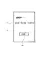
- FIG. 3 is a diagram illustrating a display example of the display unit 4.
- a screen during a call is displayed, and on this screen, an appropriate message (for example, “busy... A notification text, a telephone number of a call destination such as “090-1234-5678”, and the like, and a software button 4a for ending the call are displayed.
- an appropriate message for example, “busy... A notification text, a telephone number of a call destination such as “090-1234-5678”, and the like, and a software button 4a for ending the call are displayed.
- the user touches a predetermined position on the touch panel 3 (the position of the software button 4a) with a fingertip or the like.
- FIG. 4 is a diagram showing a flow of the touch operation valid / invalid determination program.
- This touch operation valid / invalid determination program is a part of a control program periodically executed by the CPU 10a of the central control unit 10.
- the illustrated determination program it is determined whether or not “expiration” is detected from the detection result of the expiration detection unit 7 (step S1). If the expiration is not detected, the touch operation on the touch panel 3 is set to “valid” (step S2). On the other hand, if the expiration is detected, the touch operation on the touch panel 3 is set to “disable” (step S3). End this flow.
- “Valid” means that the touch operation on the software button 4a in FIG. 3 is validated. In this case, when a predetermined position on the touch panel 3 (the position of the software button 4a) is touched, the call is terminated. On the other hand, “invalid” means to invalidate the touch operation on the software button 4a in FIG. 3. In this case, even if a predetermined position (position of the software button 4a) on the touch panel 3 is touched, the call is not ended.
- the exhalation blown to the microphone 6 is detected, and the operation of the touch panel 3 is enabled or disabled based on the detection result.
- the touch panel 3 touches the cheek during a call.
- the unintentional touch operation (touching the software button 4a with the cheek) is invalidated, and a specific effect that unintentional call disconnection can be avoided is obtained.
- exhalation detecting means 7 and a simple determination program (touch operation valid / invalid determination program) as shown in FIG. Since a mechanical structure is not required, there is an advantage that miniaturization of the mobile phone 1 is not hindered. Furthermore, since it is generally impossible for a person to speak without exhaling, it can be said that there is a close inseparable relationship between call and exhalation, so the call determination based on exhalation is accurate, and the second relationship at the beginning There is also an advantage of not incurring false detections such as technology (determining that a call is in progress even when not in a call, or vice versa).
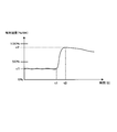
- FIG. 5 is a diagram illustrating detection characteristics of the humidity sensor.
- the vertical axis represents relative humidity (% RH), and the horizontal axis represents time (S).
- relative humidity relative humidity
- % RH relative humidity
- S time
- the humidity sensor detects the relative humidity of the surrounding environment.
- “x1” on the vertical axis indicates the relative humidity of the surrounding environment.
- the vertical axis “x2” indicates the relative humidity after the increase.
- the period from “t1” to “t2” on the horizontal axis is the period during which the breath is blown.
- the relative humidity detected by the humidity sensor decreases at a slow rate, and after a certain period of time, returns to the relative humidity of the surrounding environment.
- the determination of “exhalation” when a humidity sensor having such characteristics is used for the exhalation detection unit 7 may be determined by detecting a rapidly rising change portion (t1 to t2 in FIG. 5) of the characteristic line. .
- the amount of change can be calculated by “x2-x1 / t2-t1”. In this way, it is possible to avoid erroneous determination associated with a temporary humidity change (for example, a humidity change immediately after entering the room from the outside).
- a temporary humidity change for example, a humidity change immediately after entering the room from the outside.
- the ratio of the actual water vapor amount at that time to the maximum water vapor amount that can be contained in air at a certain temperature is referred to as relative humidity (hereinafter referred to as “humidity”).
- the humidity also changes. For example, when entering a heated room from outside. In such a case, since the cellular phone 1 is cold, when the indoor air touches the cellular phone 1, the temperature of the air decreases, and accordingly, the humidity around the cellular phone 1 increases. Such humidity changes should not be detected because they are not due to exhalation. Humidity changes due to exhalation and humidity changes, for example, when entering a heated room from the outside, may be different. If the specific humidity change due to exhalation can be distinguished from, for example, the change amount (x2 ⁇ x1 / t2 ⁇ t1), the erroneous determination associated with the “temporary humidity change” can be avoided.
- the humidity sensor has the property that it takes a long time to return to the original state once the humidity rises. You may make it avoid misjudgment using this property.
- FIG. 6 is a diagram illustrating avoidance of erroneous determination of the humidity sensor.
- the time (t3 to t4) required to reach a predetermined humidity (y2) slightly lower than the humidity (y1) after reaching a high humidity (y1) as the breath is blown is the humidity rise time ( This is significantly longer than t1 to t2) in FIG. Therefore, when a state showing a long fall time is observed after such a short rise time, it may be determined as “exhalation”. It is possible to avoid erroneous determination when a temporary output fluctuation due to noise or the like occurs.
- the “during a call” of the mobile phone 1 is taken as an example, but the present invention is not limited to this.
- any electronic device including a display device with a touch panel and a microphone may be used.
- the electronic device may be an electronic device that plays a game by blowing or uttering a voice toward the microphone, or It may be a recording device such as an IC recorder, an electronic dictionary, a tablet PC, or a notebook PC. In either case, it is only necessary to detect “exhalation” and invalidate the touch operation on the touch panel.
- control mode when detecting exhalation is not limited to “invalid” of touch operation.
- the display state of the display unit may be changed.
- the progress display of a game or the like may be controlled by detecting expiration, or the detection sensitivity of the touch panel 3 may be controlled at the time of expiration detection.
- the latter mode controlling the detection sensitivity of the touch panel 3 when detecting exhalation
- if the surface of the touch panel 3 is dirty, finger slipping is poor and in order to eliminate this, the panel surface is blown to remove the dirt. This is because the slipping is improved, and the operability can be improved by controlling the detection sensitivity of the touch panel 3 in accordance with the slipping.
- the transmissive touch panel 3 is taken as an example, but the present invention is not limited to this. Any device that detects a user's touch operation may be used.
- a “touchpad” made of an opaque material may be used.
- the sensor used for the breath detection unit 7 is not limited to the humidity sensor. It may be a temperature sensor, an odor sensor, a carbon dioxide sensor, or the like. Appropriate ones may be selectively used in consideration of the detection sensitivity of “exhalation”, the responsiveness or cost of detection, and the like.
- the breath detection unit 7 can also be used as a "bouth odor detection unit” and can be used as a so-called etiquette sensor, especially for women who are concerned about bad breath. preferable.
- all or some of the above sensors may be used for the breath detection unit 7.
- the output of each sensor may be weighted, and expiration may be determined by combining the weighted outputs.
- weighting may be performed in the order of humidity> temperature> odor> carbon dioxide.
- this order is an example.
- the actual rank should be set according to the degree of participation of physical quantities related to expiration.
- the humidity sensor has a property that it takes a considerably long time for the humidity increased by blowing air to return to the original environmental humidity. However, the increased humidity becomes the original environmental humidity. If the telephone call state continues even after returning, it may be determined that the telephone has been forgotten to be disconnected, and may be automatically disconnected.
- FIG. 7 is a diagram illustrating the principle of Supplementary Note 1.
- the display device (100) according to appendix 1 includes a touch detection means (101) for detecting a user's touch operation, a display means (102) for displaying arbitrary information, and the touch detection.
- a voice input means (103) disposed near the means (100), a breath detection means (104) for detecting a breath blown toward the voice input means (103), and a breath detection means (104)
- a change means (105) for changing a detection mode of the touch detection means (101) or a display mode of the display means (102) when expiration is detected is provided.
- the detection mode of the touch detection means (101) is changed. Touch operation can be surely avoided.
- the display device according to appendix 2 is the display device according to appendix 1, wherein the breath detection means detects breath based on any one of temperature, humidity, odor, carbon dioxide, or some or all of them. It is characterized by. According to Supplementary Note 2, expiration can be detected using various physical quantities related to breath such as temperature, humidity, odor, and carbon dioxide.
- the display device according to appendix 3 is the display device according to appendix 1 or appendix 2, wherein the changing means invalidates the touch operation of the touch detection means when expiration is detected by the expiration detection means. It is characterized by. According to Supplementary Note 3, exhalation can be detected to invalidate the touch operation, and inadvertent touch operation associated with cheek touch in particular can be avoided.
- the display control method includes an expiration detection step of detecting an exhalation blown toward a voice input unit disposed in the vicinity of a touch detection unit that detects a user's touch operation, and the expiration is detected by the expiration detection step.
- the detection mode of the touch detection unit is changed. The unintentional touch operation by can be surely avoided.
- the program according to attachment 5 includes a touch detection unit that detects a user's touch operation, a display unit that displays arbitrary information, a voice input unit that is disposed near the touch detection unit, and a voice input unit.
- the function of Supplementary Note 1 can be provided in the form of a program.
Landscapes
- Engineering & Computer Science (AREA)
- Human Computer Interaction (AREA)
- Computer Networks & Wireless Communication (AREA)
- Signal Processing (AREA)
- Computer Hardware Design (AREA)
- Theoretical Computer Science (AREA)
- Environmental & Geological Engineering (AREA)
- Physics & Mathematics (AREA)
- General Engineering & Computer Science (AREA)
- General Physics & Mathematics (AREA)
- Telephone Function (AREA)
Description
本発明は、表示装置、表示制御方法及びプログラムに関し、詳しくは、タッチパネル付の表示装置、表示制御方法及びプログラムに関する。
近年、タッチパネル付の表示装置を備えた電子機器の普及が著しい。たとえば、スマートフォンと呼ばれる携帯電話機のほとんどはタッチパネル付の表示装置を備えている。この種の携帯電話機は、液晶ディスプレイ等の画面前面にタッチパネルを配設し、そのタッチパネルを透して表示画面が見えるようになっている。表示画面には、適切にデザインされたソフトウェアボタンを任意に配置することが可能であり、そのソフトウェアボタンに対するユーザ操作(つまり、タッチパネルへの指先等のタッチ操作)に応答して、上記のソフトウェアボタンに対する操作イベントを発生することができる。
このように、タッチパネル付の表示装置を備えた電子機器は、画面表示に対するタッチという直感的な操作が可能であることから使い勝手がよく、しかも、物理的なボタンの代わりに設計の自由度が高いソフトウェアボタンを用いることができるという利点がある。
しかしながら、タッチパネル付の表示装置を備えた電子機器は、使い方によって以下の不都合が生じることがある。たとえば、携帯電話機で通話中に、タッチパネルが頬などに触れると、不本意なタッチ操作が生じてしまうことがある。
不本意なタッチ操作を回避する関連技術としては、たとえば、以下のようなものが知られている。
<第1関連技術>
受話器背面にスイッチを設け、受話器が耳に押し付けられたことをスイッチで検出してタッチ操作を無効にする(たとえば、特許文献1参照)。
<第2関連技術>
電話機内部に傾きセンサを設け、この傾きセンサで通話中を判定してタッチ操作を無効にする(たとえば、特許文献2参照)。
<第1関連技術>
受話器背面にスイッチを設け、受話器が耳に押し付けられたことをスイッチで検出してタッチ操作を無効にする(たとえば、特許文献1参照)。
<第2関連技術>
電話機内部に傾きセンサを設け、この傾きセンサで通話中を判定してタッチ操作を無効にする(たとえば、特許文献2参照)。
前記の第1及び第2関連技術は、いずれも通話中を検出してタッチ操作を無効にする点で一応の効果を認められるが、第1関連技術は通話の検出を機械的に行う仕組みのため、機器の小型化を阻害するし、また、第2関連技術は必ずしも全てのユーザが特定の傾きで通話を行うとは限らないから、誤検出(通話中でないにもかかわらず通話中と判断したり、その逆を判断したり)を否めないという欠点がある。
そこで、本発明の目的は、不本意なタッチ操作を確実に回避することができる表示装置、表示制御方法及びプログラムを提供することにある。
本発明は、ユーザのタッチ操作を検出するタッチ検出手段と、任意の情報を表示する表示手段と、前記タッチ検出手段の近くに配置された音声入力手段と、前記音声入力手段に向かって吹きかけられる呼気を検出する呼気検出手段と、前記呼気検出手段によって呼気が検出されたときに前記タッチ検出手段の検出態様または前記表示手段の表示態様を変更する変更手段とを備えたことを特徴とする表示装置である。
本発明によれば、不本意なタッチ操作を確実に回避することができる。
以下、本発明の実施形態を、携帯電話機への適用を例にして、図面を参照しながら説明する。
図1は、実施形態に係る携帯電話機の外観図である。この図において、携帯電話機1は、手持ちに適した形状、たとえば、薄型箱形状の筐体2の主面(表面であって主たる操作対象となる面のこと)にタッチパネル3を設けるとともに、そのタッチパネル3の背面に液晶ディスプレイやELパネルなどの二次元表示デバイスからなる表示部4を設け、また、そのタッチパネル3の上辺近くに受話器としてのスピーカ5を設け、さらに、そのタッチパネル3の下辺近くに送話器としてのマイク6と呼気検出部7とを設けている。
図1は、実施形態に係る携帯電話機の外観図である。この図において、携帯電話機1は、手持ちに適した形状、たとえば、薄型箱形状の筐体2の主面(表面であって主たる操作対象となる面のこと)にタッチパネル3を設けるとともに、そのタッチパネル3の背面に液晶ディスプレイやELパネルなどの二次元表示デバイスからなる表示部4を設け、また、そのタッチパネル3の上辺近くに受話器としてのスピーカ5を設け、さらに、そのタッチパネル3の下辺近くに送話器としてのマイク6と呼気検出部7とを設けている。
ここで、「近く」とは、少なくとも筐体2の主面の端からタッチパネル3の端までの間のいわゆる額縁内の任意の位置のことをいう。一般的に額縁は、筐体2の小型化要求に伴ってできるだけ狭くなるように設計されており、したがって、前記のスピーカ5やマイク6及び呼気検出部7は、そのきわめて狭い額縁に収められることになるから、結局のところ、タッチパネル3の「近く」に設けられる、と表現しても差し支えない。
なお、筐体2の任意部分に、電源スイッチやバッテリ充電用端子などが設けられているが、図では省略している。
図2は、携帯電話機1の概念的な内部ブロック図である。この図において、携帯電話機1は、無線部8、音声入出力部9、呼気検出部7、中央制御部10、表示部4、タッチパネル3、電源部11を備える。
無線通信部8は、アンテナ8aを介して最寄りの基地局(図示略)との間で無線によるデジタルデータの送受信を行う。デジタルデータには、電話の着呼や発呼の情報および音声通話の情報が含まれる。この無線通信部8は、中央制御部10からの制御に従って、上記のデジタルデータの送信や受信を行う。
音声入出力部9は、中央制御部10からの制御により、マイク6で拾った音声信号をデジタルデータに変換して中央制御部10に出力したり、中央制御部10から出力されたデジタルの音声信号をアナログ信号に変換してスピーカ5から拡声したりする。マイク6やスピーカ5は電話の送受話用であるが、スピーカ5は、さらに電話の着信音鼓動にも用いられる。
表示部4は、先にも説明したとおり、その前面に、人体の一部の接触を検知できるタッチパネル3を併設している。タッチパネル3は、たとえば、静電容量方式のものであってもよい。なお、「併設」は、表示部4の前面にタッチパネル3を“接着固定”するという意味であってもよく、あるいは、“非接着”で単に動かない(面方向にずれない)という意味であってもよい。また、多くのタッチパネルは、それ自体が独立した1つの部品であるが、これに限らず、たとえば、表示部4に組み込まれた(一般的には保護ガラスと表示層との間にタッチパネル層が挟み込まれている)一体型のものであってもよい。
電源部11は、一次電池または充電可能な二次電池からなるバッテリを含み、このバッテリの電力から携帯電話機1の動作に必要な各種電源電圧を発生して各部に供給する。
中央制御部10は、コンピュータまたはマイクロコンピュータ(以下、CPU)10a、読み出し専用半導体メモリ(以下、ROM)10b、高速半導体メモリ(以下、RAM)10cおよび書き換え可能な不揮発性半導体メモリ(フラッシュメモリやPROMなど。以下、PROM)10dならびに不図示の周辺回路を含むプログラム制御方式の制御要素であり、あらかじめROM10bやPROM10dに格納されている制御プログラムをRAM10cにロードしてCPU10aで実行することにより、各種の処理を逐次に実行して、この携帯電話機1の全体動作を統括制御する。
呼気検出部7は、本実施形態に特有の構成要素の1つであり、具備すべき重要な機能的要件は、ユーザの「呼気」を検出する点にあり、特にマイク6に向かって吹きかけられる呼気を検出する点にある。
ここで、呼気とは、広義には人体の鼻や口から吐き出される息のことをいうが、本実施形態では、発話(発声)に伴って自然に口や鼻から吐き出される息、または、意図的に口から吐き出される息のことをいう。この呼気検出部7に使用可能な検出デバイスは、たとえば、温度を検出するもの、水分量を検出するもの、臭気を検出するもの、二酸化炭素(CO2)を検出するものなど、様々考えられるが、要は、息に関係する物理量(温度、湿度、臭気、二酸化炭素)を検出できるセンサを用いればよい。具体的には、温度センサ、湿度センサ、臭いセンサ、CO2センサなどを単独で又は組み合わせて使用することができる。これらのセンサは、今日、小型化がめざましく、しかも高性能且つ安定した出力が得られる低価格のものが入手可能なので、実施形態の呼気検出部7に容易に用いることができる。
以下、説明の便宜上、呼気検出部7は、湿度センサによって水分量(具体的には相対湿度)を計測し、その水分量によって呼気であるか否かを検出するもとする。
次に、実施形態の動作について説明する。
図3は、表示部4の表示例を示す図である。この図において、タッチパネル3を透して見える表示部4には、たとえば、通話中の画面が表示されており、この画面には、適当なメッセージ(たとえば、“通話中・・・・”といった動作告知文や“090-1234-5678”といった通話先の電話番号など)が表示されているとともに、通話終了用のソフトウェアボタン4aが表示されている。通話を終了する際、ユーザはタッチパネル3の所定位置(ソフトウェアボタン4aの位置)を指先等でタッチする。
図3は、表示部4の表示例を示す図である。この図において、タッチパネル3を透して見える表示部4には、たとえば、通話中の画面が表示されており、この画面には、適当なメッセージ(たとえば、“通話中・・・・”といった動作告知文や“090-1234-5678”といった通話先の電話番号など)が表示されているとともに、通話終了用のソフトウェアボタン4aが表示されている。通話を終了する際、ユーザはタッチパネル3の所定位置(ソフトウェアボタン4aの位置)を指先等でタッチする。
図4は、タッチ操作有効/無効判定プログラムのフローを示す図である。このタッチ操作有効/無効判定プログラムは、中央制御部10のCPU10aで定期的に実行される制御プログラムの一部である。図示の判定プログラムを開始すると、呼気検出部7の検出結果から「呼気」を検出したか否かを判定する(ステップS1)。そして、呼気検出でなければ、タッチパネル3のタッチ操作を「有効」とし(ステップS2)、一方、呼気検出であれば、タッチパネル3のタッチ操作を「無効」とし(ステップS3)、いずれの場合も今回のフローを終了する。
「有効」とは、図3のソフトウェアボタン4aに対するタッチ操作を有効にすることをいい、この場合、タッチパネル3の所定位置(ソフトウェアボタン4aの位置)がタッチされると通話を終了する。一方、「無効」とは、図3のソフトウェアボタン4aに対するタッチ操作を無効にすることをいい、この場合、タッチパネル3の所定位置(ソフトウェアボタン4aの位置)がタッチされても通話は終了されない。
以上のとおり、本実施形態では、マイク6に吹きかけられる呼気を検出し、その検出結果に基づいてタッチパネル3の操作を有効にしたり無効にしたりするから、たとえば、通話中にタッチパネル3が頬に触れた場合の不本意なタッチ操作(頬によるソフトウェアボタン4aへのタッチ)を無効にして、意図しない通話切断を回避できるという特有の効果が得られる。
また、そのために必要な要件は、少なくとも呼気検出手段7と、図4に示すような単純な判定プログラム(タッチ操作有効/無効判定プログラム)だけでよく、冒頭の第1関連技術のような複雑な機械的構造を必要としないから、携帯電話機1の小型化を阻害しないというメリットもある。さらに、一般的に人は息を吐かずに声を発することができないから、通話と呼気は密接不可分な関係にあるといえるので、呼気に基づく通話の判定は正確であり、冒頭の第2関連技術のような誤検出(通話中でないにもかかわらず通話中と判断したり、その逆を判断したり)を招かないというメリットもある。
ここで湿度センサの検出特性について補足説明する。
図5は、湿度センサの検出特性を示す図である。この図において、縦軸は相対湿度(%RH)、横軸は時間(S)である。ちなみに、相対湿度(relative humidity)とは、一般的にある気温で大気中に含まれる水蒸気の量(重量絶対湿度)を、その温度の飽和水蒸気量(重量絶対湿度)で割った値(単位:%)のことをいう。相対湿度100%で大気中の水蒸気量が飽和となり、結露を生じる。また、そのときの温度を露点温度という。相対湿度の値は0%以上、100%以下の値をとる。
図5は、湿度センサの検出特性を示す図である。この図において、縦軸は相対湿度(%RH)、横軸は時間(S)である。ちなみに、相対湿度(relative humidity)とは、一般的にある気温で大気中に含まれる水蒸気の量(重量絶対湿度)を、その温度の飽和水蒸気量(重量絶対湿度)で割った値(単位:%)のことをいう。相対湿度100%で大気中の水蒸気量が飽和となり、結露を生じる。また、そのときの温度を露点温度という。相対湿度の値は0%以上、100%以下の値をとる。
湿度センサに息を吹きかけないとき、湿度センサは周囲環境の相対湿度を検出する。図中縦軸の「x1」は周囲環境の相対湿度を示している。今、この状態で湿度センサに息を吹きかけると、湿度センサで検出される相対湿度が急激に上昇する。図中縦軸の「x2」は上昇後の相対湿度を示している。図中横軸の「t1」から「t2」までが、息を吹きかけている期間である。息を吹きかけ終わる「t2」以降、湿度センサで検出される相対湿度は、ゆっくりとした速度で低下し、ある時間の経過後に、周囲環境の相対湿度に戻る。
このような特性を有する湿度センサを呼気検出部7に使用する場合の「呼気」の判定は、特性線の急激な上昇変化部分(図5のt1~t2)を検出して判定してもよい。変化量は「x2-x1/t2-t1」で算出できる。このようにすると、一時的な湿度変化(たとえば、屋外から室内に入った直後の湿度変化など)に伴う誤判定を回避できる。先にも説明したとおり、ある温度の空気中に含むことができる最大水蒸気量に対して、その時点での実際の水蒸気量の割合を表したものを相対湿度(以下「湿度」)という。このため、水蒸気量が一定でも温度が変化すれば、湿度も変化する。たとえば、屋外から暖房の効いた室内に入ったときのような場合である。このような場合、携帯電話機1は冷えているため、室内の空気が携帯電話機1に触れると、空気の温度が下がり、それに伴って携帯電話機1の周囲の湿度が高くなる。こうした湿度変化は、呼気によるものではないので検出すべきではない。呼気による湿度変化と、たとえば、屋外から暖房の効いた室内に入ったときのような湿度変化は、異なる変化を示すと思われる。呼気による特有の湿度変化を、たとえば、前記の変化量(x2-x1/t2-t1)から区別することができれば、前記の「一時的な湿度変化」に伴う誤判定を回避することができる。
また、上記のとおり、湿度センサは、一度湿度が上がると元の状態に戻るのに長い時間を要する性質がある。この性質を利用して、誤判定を回避するようにしてもよい。
図6は、湿度センサの誤判定回避を示す図である。この図において、息の吹きかけに伴って高い湿度(y1)に達した後、その湿度から少し下がった所定の湿度(y2)に到達するまでの時間(t3~t4)は、湿度の立ち上がり時間(図5のt1~t2)に比べて大幅に長くなる。したがって、そのような短い立ち上がり時間の後に長い立ち下がり時間を示す状態が観測された場合に「呼気」であると判定してもよい。ノイズ等による一時的な出力変動が発生した場合の誤判定を回避できる。
なお、以上の説明では、携帯電話機1の「通話時」を例にしたが、これに限定されない。要はタッチパネル付の表示装置とマイクを備えた電子機器であればよく、たとえば、マイクに向かって息を吹きかけたり、声を発したりすることによってゲームを行う電子機器であってもよく、あるいは、ICレコーダ等の録音装置や電子辞書、タブレットPC、ノートPCなどであってもよい。いずれの場合も「呼気」を検出してタッチパネルのタッチ操作を無効にすればよい。
また、呼気検出時の制御態様もタッチ操作の「無効」のみに限定されない。表示部の表示状態を変更するなどの態様であってもよい。たとえば、呼気を検出してゲームなどの進行表示を制御してもよいし、あるいは、呼気検出時にタッチパネル3の検出感度を制御してもよい。特に後者の態様(呼気検出時にタッチパネル3の検出感度を制御する)は、タッチパネル3の表面に汚れがあると指の滑りが悪く、これを解消するためにパネル面に息を吹きかけて汚れを落とすと、滑りがよくなるからであり、滑りの良否に合わせてタッチパネル3の検出感度を制御することによって、操作性の向上が見込めるからである。
また、以上の説明では、透過型のタッチパネル3を例にしたが、これに限定されない。ユーザのタッチ操作を検出するものであればよく、たとえば、不透明な素材からなる「タッチパッド」などであってもよい。
また、先にも説明したとおり、呼気検出部7に用いるセンサは湿度センサに限定されない。温度センサや臭気センサあるいは二酸化炭素センサなどであってもよい。「呼気」の検出感度や検出の応答性またはコストなどを勘案して適切なものを選択的に使用すればよい。
ちなみに、呼気検出部7に臭いセンサを用いた場合は、その呼気検出部7を「口臭検出部」としても利用でき、いわゆるエチケットセンサとして用いることができるので、特に口臭を気にする女性向けに好ましい。
また、所望であれば、上記のセンサ(湿度センサ、温度センサ、臭いセンサ、二酸化炭素センサ)の全てまたはいくつかを呼気検出部7に用いてもよい。この場合、各センサの出力に重み付けを加え、重み付け後の出力を組み合わせて呼気を判定するようにしてもよい。たとえば、全てのセンサを用いる場合は、湿度>温度>臭気>二酸化炭素の順位で重み付けをしてもよい。ただし、この順位は一例である。実際の順位は呼気に関係する物理量の関与の度合いに応じて設定すべきことはもちろんである。
また、呼気検出部7の検出結果に基づいて、たとえば、電話の切り忘れ防止対策を講じることもできる。すなわち、図6に示したとおり、湿度センサは息の吹きかけによって高くなった湿度が元の環境湿度に戻るまでに相当長い時間を要するという性質があるが、高くなった湿度が元の環境湿度に戻ってもなお通話状態が続いていた場合には、電話の切り忘れであると判断し、自動的に切断するようにしてもよい。
上記の実施形態の一部又は全部は、以下の付記のようにも記載されうるが、以下には限られない。
(付記1)
図7は、付記1の原理構成図である。この図に示すように、付記1に記載の表示装置(100)は、ユーザのタッチ操作を検出するタッチ検出手段(101)と、任意の情報を表示する表示手段(102)と、前記タッチ検出手段(100)の近くに配置された音声入力手段(103)と、前記音声入力手段(103)に向かって吹きかけられる呼気を検出する呼気検出手段(104)と、前記呼気検出手段(104)によって呼気が検出されたときに前記タッチ検出手段(101)の検出態様または前記表示手段(102)の表示態様を変更する変更手段(105)とを備えたことを特徴とする。
付記1によれば、呼気が検出されたときにタッチ検出手段(101)の検出態様を変更するので、たとえば、この「変更」を「タッチ操作の無効」とすれば、頬のタッチによる不本意なタッチ操作を確実に回避することができる。
(付記1)
図7は、付記1の原理構成図である。この図に示すように、付記1に記載の表示装置(100)は、ユーザのタッチ操作を検出するタッチ検出手段(101)と、任意の情報を表示する表示手段(102)と、前記タッチ検出手段(100)の近くに配置された音声入力手段(103)と、前記音声入力手段(103)に向かって吹きかけられる呼気を検出する呼気検出手段(104)と、前記呼気検出手段(104)によって呼気が検出されたときに前記タッチ検出手段(101)の検出態様または前記表示手段(102)の表示態様を変更する変更手段(105)とを備えたことを特徴とする。
付記1によれば、呼気が検出されたときにタッチ検出手段(101)の検出態様を変更するので、たとえば、この「変更」を「タッチ操作の無効」とすれば、頬のタッチによる不本意なタッチ操作を確実に回避することができる。
(付記2)
付記2に記載の表示装置は、付記1に記載の表示装置において、前記呼気検出手段は、温度、湿度、臭気、二酸化炭素のいずれかまたはそれらのいくつかもしくは全てに基づいて呼気を検出することを特徴とする。
付記2によれば、温度、湿度、臭気、二酸化炭素といった息に関係する様々な物理量を用いて呼気を検出することができる。
付記2に記載の表示装置は、付記1に記載の表示装置において、前記呼気検出手段は、温度、湿度、臭気、二酸化炭素のいずれかまたはそれらのいくつかもしくは全てに基づいて呼気を検出することを特徴とする。
付記2によれば、温度、湿度、臭気、二酸化炭素といった息に関係する様々な物理量を用いて呼気を検出することができる。
(付記3)
付記3に記載の表示装置は、付記1または付記2に記載の表示装置において、前記変更手段は、前記呼気検出手段によって呼気が検出されたときに前記タッチ検出手段のタッチ操作を無効にすることを特徴とする。
付記3によれば、呼気を検出してタッチ操作を無効にすることができ、特に頬のタッチに伴う不本意なタッチ操作を回避できる。
付記3に記載の表示装置は、付記1または付記2に記載の表示装置において、前記変更手段は、前記呼気検出手段によって呼気が検出されたときに前記タッチ検出手段のタッチ操作を無効にすることを特徴とする。
付記3によれば、呼気を検出してタッチ操作を無効にすることができ、特に頬のタッチに伴う不本意なタッチ操作を回避できる。
(付記4)
付記4に記載の表示制御方法は、ユーザのタッチ操作を検出するタッチ検出手段の近くに配置された音声入力手段に向かって吹きかけられる呼気を検出する呼気検出工程と、前記呼気検出工程によって呼気が検出されたときに前記タッチ検出手段の検出態様または任意の情報を表示する表示手段の表示態様を変更する変更工程とを含むことを特徴とする。
付記4によれば、付記1と同様に、呼気が検出されたときにタッチ検出手段の検出態様を変更するので、たとえば、この「変更」を「タッチ操作の無効」とすれば、頬のタッチによる不本意なタッチ操作を確実に回避することができる。
付記4に記載の表示制御方法は、ユーザのタッチ操作を検出するタッチ検出手段の近くに配置された音声入力手段に向かって吹きかけられる呼気を検出する呼気検出工程と、前記呼気検出工程によって呼気が検出されたときに前記タッチ検出手段の検出態様または任意の情報を表示する表示手段の表示態様を変更する変更工程とを含むことを特徴とする。
付記4によれば、付記1と同様に、呼気が検出されたときにタッチ検出手段の検出態様を変更するので、たとえば、この「変更」を「タッチ操作の無効」とすれば、頬のタッチによる不本意なタッチ操作を確実に回避することができる。
(付記5)
付記5に記載のプログラムは、ユーザのタッチ操作を検出するタッチ検出手段と、任意の情報を表示する表示手段と、前記タッチ検出手段の近くに配置された音声入力手段と、前記音声入力手段に向かって吹きかけられる呼気を検出する呼気検出手段とを有する表示装置のコンピュータに、
前記呼気検出手段によって呼気が検出されたときに前記タッチ検出手段の検出態様または前記表示手段の表示態様を変更する変更手段としての機能を与えることを特徴とする。
付記5によれば、付記1の機能をプログラムの形で提供することができる。
付記5に記載のプログラムは、ユーザのタッチ操作を検出するタッチ検出手段と、任意の情報を表示する表示手段と、前記タッチ検出手段の近くに配置された音声入力手段と、前記音声入力手段に向かって吹きかけられる呼気を検出する呼気検出手段とを有する表示装置のコンピュータに、
前記呼気検出手段によって呼気が検出されたときに前記タッチ検出手段の検出態様または前記表示手段の表示態様を変更する変更手段としての機能を与えることを特徴とする。
付記5によれば、付記1の機能をプログラムの形で提供することができる。
4 表示部(表示手段)
5 タッチパネル(タッチ検出手段)
6 マイク(音声入力手段)
7 呼気検出部(呼気検出手段)
10 中央制御部(変更手段)
10a CPU(コンピュータ)
100 表示装置
101 タッチ検出手段
102 表示手段
103 音声入力手段
104 呼気検出手段
105 変更手段
5 タッチパネル(タッチ検出手段)
6 マイク(音声入力手段)
7 呼気検出部(呼気検出手段)
10 中央制御部(変更手段)
10a CPU(コンピュータ)
100 表示装置
101 タッチ検出手段
102 表示手段
103 音声入力手段
104 呼気検出手段
105 変更手段
Claims (5)
- ユーザのタッチ操作を検出するタッチ検出手段と、
任意の情報を表示する表示手段と、
前記タッチ検出手段の近くに配置された音声入力手段と、
前記音声入力手段に向かって吹きかけられる呼気を検出する呼気検出手段と、
前記呼気検出手段によって呼気が検出されたときに前記タッチ検出手段の検出態様または前記表示手段の表示態様を変更する変更手段と
を備えたことを特徴とする表示装置。 - 前記呼気検出手段は、温度、湿度、臭気、二酸化炭素のいずれかまたはそれらのいくつかもしくは全てに基づいて呼気を検出することを特徴とする請求項1に記載の表示装置。
- 前記変更手段は、前記呼気検出手段によって呼気が検出されたときに前記タッチ検出手段のタッチ操作を無効にすることを特徴とする請求項1または請求項2に記載の表示装置。
- ユーザのタッチ操作を検出するタッチ検出手段の近くに配置された音声入力手段に向かって吹きかけられる呼気を検出する呼気検出工程と、
前記呼気検出工程によって呼気が検出されたときに前記タッチ検出手段の検出態様または任意の情報を表示する表示手段の表示態様を変更する変更工程と
を含むことを特徴とする表示制御方法。 - ユーザのタッチ操作を検出するタッチ検出手段と、任意の情報を表示する表示手段と、前記タッチ検出手段の近くに配置された音声入力手段と、前記音声入力手段に向かって吹きかけられる呼気を検出する呼気検出手段とを有する表示装置のコンピュータに、
前記呼気検出手段によって呼気が検出されたときに前記タッチ検出手段の検出態様または前記表示手段の表示態様を変更する変更手段
としての機能を与えることを特徴とするプログラム。
Priority Applications (1)
| Application Number | Priority Date | Filing Date | Title |
|---|---|---|---|
| PCT/JP2012/005473 WO2014033780A1 (ja) | 2012-08-30 | 2012-08-30 | 表示装置、表示制御方法及びプログラム |
Applications Claiming Priority (1)
| Application Number | Priority Date | Filing Date | Title |
|---|---|---|---|
| PCT/JP2012/005473 WO2014033780A1 (ja) | 2012-08-30 | 2012-08-30 | 表示装置、表示制御方法及びプログラム |
Publications (1)
| Publication Number | Publication Date |
|---|---|
| WO2014033780A1 true WO2014033780A1 (ja) | 2014-03-06 |
Family
ID=50182632
Family Applications (1)
| Application Number | Title | Priority Date | Filing Date |
|---|---|---|---|
| PCT/JP2012/005473 Ceased WO2014033780A1 (ja) | 2012-08-30 | 2012-08-30 | 表示装置、表示制御方法及びプログラム |
Country Status (1)
| Country | Link |
|---|---|
| WO (1) | WO2014033780A1 (ja) |
Cited By (1)
| Publication number | Priority date | Publication date | Assignee | Title |
|---|---|---|---|---|
| CN109240537A (zh) * | 2018-08-23 | 2019-01-18 | 硅谷数模半导体(北京)有限公司 | 触摸屏的控制方法、装置、设备、存储介质及处理器 |
Citations (4)
| Publication number | Priority date | Publication date | Assignee | Title |
|---|---|---|---|---|
| JPH11146057A (ja) * | 1997-11-04 | 1999-05-28 | Tokai Rika Co Ltd | 移動電話及び個人識別システム |
| JP2007129411A (ja) * | 2005-11-02 | 2007-05-24 | Yamaha Corp | 通信端末 |
| JP2008141688A (ja) * | 2006-12-05 | 2008-06-19 | Funai Electric Co Ltd | 携帯端末機器 |
| JP2010026747A (ja) * | 2008-07-18 | 2010-02-04 | Sharp Corp | 認証装置、並びに、それを備える携帯端末装置及び鍵開閉管理装置 |
-
2012
- 2012-08-30 WO PCT/JP2012/005473 patent/WO2014033780A1/ja not_active Ceased
Patent Citations (4)
| Publication number | Priority date | Publication date | Assignee | Title |
|---|---|---|---|---|
| JPH11146057A (ja) * | 1997-11-04 | 1999-05-28 | Tokai Rika Co Ltd | 移動電話及び個人識別システム |
| JP2007129411A (ja) * | 2005-11-02 | 2007-05-24 | Yamaha Corp | 通信端末 |
| JP2008141688A (ja) * | 2006-12-05 | 2008-06-19 | Funai Electric Co Ltd | 携帯端末機器 |
| JP2010026747A (ja) * | 2008-07-18 | 2010-02-04 | Sharp Corp | 認証装置、並びに、それを備える携帯端末装置及び鍵開閉管理装置 |
Cited By (1)
| Publication number | Priority date | Publication date | Assignee | Title |
|---|---|---|---|---|
| CN109240537A (zh) * | 2018-08-23 | 2019-01-18 | 硅谷数模半导体(北京)有限公司 | 触摸屏的控制方法、装置、设备、存储介质及处理器 |
Similar Documents
| Publication | Publication Date | Title |
|---|---|---|
| US8954099B2 (en) | Layout design of proximity sensors to enable shortcuts | |
| US10234923B2 (en) | Methods and devices for waking up a screen | |
| ES3034134T3 (en) | Multimedia file playback control method and terminal device | |
| JP5606205B2 (ja) | 携帯端末装置 | |
| JP2012186620A (ja) | 表示装置、表示制御方法及びプログラム | |
| US9392088B2 (en) | Intelligent muting of a mobile device | |
| KR20060019273A (ko) | Hmd 정보 단말기 및 키를 입력하는 장치 및 방법 | |
| CN103841258B (zh) | 使用湿度传感器控制便携式装置的方法以及便携式装置 | |
| CN110233933B (zh) | 一种通话方法、终端设备及计算机可读存储介质 | |
| CN109799924A (zh) | 防误触控制方法及装置、移动终端、计算机可读存储介质 | |
| CN107832067B (zh) | 一种应用更新方法、移动终端和计算机可读存储介质 | |
| CN108762613B (zh) | 一种状态图标显示方法及移动终端 | |
| US20110119641A1 (en) | Call connection method and apparatus in mobile terminal | |
| CN107463897A (zh) | 指纹识别方法及移动终端 | |
| CN110933505A (zh) | 一种进度调节方法及电子设备 | |
| US10156932B2 (en) | Mobile electronic device, method of controlling mobile electronic device, and recording medium | |
| CN110471808B (zh) | 一种压力按键检测方法、装置及移动终端 | |
| CN110083244B (zh) | 可穿戴设备防误触方法、可穿戴设备及存储介质 | |
| US20170097722A1 (en) | Mobile electronic device, method of controlling mobile electronic device, and recording medium | |
| JP4706629B2 (ja) | 携帯端末機器 | |
| JP6255129B1 (ja) | 電子機器 | |
| CN109040431B (zh) | 一种模式控制方法、终端及存储介质 | |
| CN110213439B (zh) | 一种消息处理方法和终端 | |
| CN107957789B (zh) | 一种文本输入方法及移动终端 | |
| JP5224960B2 (ja) | 携帯電話機 |
Legal Events
| Date | Code | Title | Description |
|---|---|---|---|
| 121 | Ep: the epo has been informed by wipo that ep was designated in this application |
Ref document number: 12883516 Country of ref document: EP Kind code of ref document: A1 |
|
| NENP | Non-entry into the national phase |
Ref country code: DE |
|
| 122 | Ep: pct application non-entry in european phase |
Ref document number: 12883516 Country of ref document: EP Kind code of ref document: A1 |
|
| NENP | Non-entry into the national phase |
Ref country code: JP |