WO2014024315A1 - Bogie for railway vehicle - Google Patents
Bogie for railway vehicle Download PDFInfo
- Publication number
- WO2014024315A1 WO2014024315A1 PCT/JP2012/070535 JP2012070535W WO2014024315A1 WO 2014024315 A1 WO2014024315 A1 WO 2014024315A1 JP 2012070535 W JP2012070535 W JP 2012070535W WO 2014024315 A1 WO2014024315 A1 WO 2014024315A1
- Authority
- WO
- WIPO (PCT)
- Prior art keywords
- shaft
- axle
- shaft spring
- box
- bogie
- Prior art date
Links
Images


Classifications
-
- B—PERFORMING OPERATIONS; TRANSPORTING
- B61—RAILWAYS
- B61F—RAIL VEHICLE SUSPENSIONS, e.g. UNDERFRAMES, BOGIES OR ARRANGEMENTS OF WHEEL AXLES; RAIL VEHICLES FOR USE ON TRACKS OF DIFFERENT WIDTH; PREVENTING DERAILING OF RAIL VEHICLES; WHEEL GUARDS, OBSTRUCTION REMOVERS OR THE LIKE FOR RAIL VEHICLES
- B61F5/00—Constructional details of bogies; Connections between bogies and vehicle underframes; Arrangements or devices for adjusting or allowing self-adjustment of wheel axles or bogies when rounding curves
- B61F5/26—Mounting or securing axle-boxes in vehicle or bogie underframes
- B61F5/30—Axle-boxes mounted for movement under spring control in vehicle or bogie underframes
- B61F5/305—Axle-boxes mounted for movement under spring control in vehicle or bogie underframes incorporating rubber springs
-
- B—PERFORMING OPERATIONS; TRANSPORTING
- B61—RAILWAYS
- B61F—RAIL VEHICLE SUSPENSIONS, e.g. UNDERFRAMES, BOGIES OR ARRANGEMENTS OF WHEEL AXLES; RAIL VEHICLES FOR USE ON TRACKS OF DIFFERENT WIDTH; PREVENTING DERAILING OF RAIL VEHICLES; WHEEL GUARDS, OBSTRUCTION REMOVERS OR THE LIKE FOR RAIL VEHICLES
- B61F5/00—Constructional details of bogies; Connections between bogies and vehicle underframes; Arrangements or devices for adjusting or allowing self-adjustment of wheel axles or bogies when rounding curves
- B61F5/26—Mounting or securing axle-boxes in vehicle or bogie underframes
- B61F5/30—Axle-boxes mounted for movement under spring control in vehicle or bogie underframes
- B61F5/36—Arrangements for equalising or adjusting the load on wheels or springs, e.g. yokes
Definitions
- the present invention relates to a bogie for a railway vehicle having a bogie frame, an axle, an axle box that supports the axle, and a support box support device that supports the axle box on the carriage frame, and in particular, the axle box when lifting the carriage frame.
- the present invention relates to a bogie for a railway vehicle including an axle box support device that suppresses separation from a bogie frame.
- Patent Document 1 discloses a structure that suppresses falling off of an axle box that rotatably supports a wheel shaft when a carriage frame constituting a railway vehicle carriage is lifted.
- This structure includes a core body fixed to the axle box, an outer member fixed to the bogie frame, and a connecting member that connects the core body and the outer member.
- One end of the connecting member that penetrates the through hole provided in the outer member is fixed to the core, and the other end of the connecting member has a flange larger than the outer diameter of the through hole but having an outer diameter. Department is provided.
- the axle box that rotatably supports the axle having a pair of wheels at both ends of the axle is not separated from the carriage frame when the carriage is lifted by a crane or the like when carrying the carriage.
- a wheel load ratio which is a ratio of loads at which the left and right wheels press the rail.
- a height adjustment plate that can adjust the distance between the bogie frame and the wheel shaft is easily inserted between the bogie frame constituting the bogie and the axle box supported by the bogie frame. It is necessary to have a structure that can be used.
- An object of the present invention is to provide a railcar bogie having a configuration that can easily adjust the wheel load ratio while preventing the axle box from falling off the bogie frame when the bogie is lifted.
- a railcar bogie of the present invention includes a side beam that constitutes a bogie frame, a shaft box that rotatably holds a wheel shaft, and a shaft spring that is disposed between the side beam and the shaft box.
- the shaft spring includes a cylindrical shaft spring, a bell-shaped shaft spring, and an elastic body disposed between the shaft spring and the shaft spring.
- an axle spring seat disposed between the axle spring lower part and the axle box.
- a hook provided at the peripheral edge of the lower surface of the lower part of the shaft spring seat, a flat shaft box upper end surface provided at the upper part of the shaft box and against which the hook contacts, and the hook And a height adjusting plate for adjusting a wheel load ratio provided between the upper end surface of the axle box.
- FIG. 1 is a top view of a railway vehicle carriage.
- FIG. 2 is a cross-sectional view taken along line AA of the side beam forming the carriage frame.
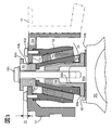
- FIG. 3 is a cross-sectional view (AA cross section of FIG. 2) of the axle box provided with the fall prevention mechanism and the height adjustment mechanism.
- FIG. 4 is a cross-sectional view showing a state when the fall prevention mechanism functions.
- FIG. 1 is a top view of a railcar bogie.
- the railcar bogie 1 is configured such that a wheel shaft provided with a total of four wheels 240 at both ends of two axles 230 is connected to the inner side of the side beam 10 constituting the bogie frame 5 (the track center side or the longitudinal axis of the axle 230). It is an inner-frame type carriage in a form arranged in the central portion of the direction.
- the wheel shaft is provided on the lower surface of both end portions in the longitudinal direction of the side beam 10 via a shaft box 64 that rotatably holds the wheel shaft.
- the carriage frame 5 includes a side beam 10 spaced in parallel, an air spring cradle 50 whose longitudinal direction is arranged parallel to the side beam 10 outside the side beam 10 (in a direction away from the center of the track), and a side beam. 10 and the air spring pedestal 50 and a transverse beam 20 penetrating in the center in the longitudinal direction.
- the side beams 10, the air spring cradle 50, and the cross beam 20 are joined together by welding.
- the shape of the cart frame 5 when viewed from above is substantially H-shaped.
- the air spring 210 is attached to the upper surface of the center portion in the longitudinal direction of the air spring cradle 50 via an air spring mounting seat, and the air spring 210 supports the weight of the vehicle body (not shown).
- a yaw damper receiver and a vehicle body In order to suppress yawing of the carriage 1 during high speed running (vibration in a horizontal plane with the center pin (not shown) as a rotation center), a yaw damper receiver and a vehicle body ( The yaw damper 200 is provided in such a manner as to be connected to the unillustrated).
- Each air spring pedestal 50 is provided with a brake device 56 at both ends in the longitudinal direction, and a brake disk (not shown) in which brake shoes of the brake device 56 are provided on both side surfaces of the wheel 240 at the time of braking. ) To obtain the braking force.
- the configuration of the railcar bogie has been described by taking the inner frame bogie 1 equipped with a disc brake as an example, the fall prevention mechanism and the height adjustment mechanism described in detail below are limited to the bogie described in FIG. However, the present invention can also be applied to an outer frame type carriage and a carriage having a tread brake.
- FIG. 2 is a cross-sectional view taken along the line AA of the side beam forming the carriage frame
- FIG. 3 is a cross-sectional view (cross section taken along the line AA in FIG. 2) of the axle box including the fall prevention mechanism and the height adjustment mechanism.
- An axial box side protrusion 64c is provided near the longitudinal center of the side beam 10 of the axle box 64, and the axle box side protrusion 64c and the side beam link receiver 10b provided on the side beam 10 are connected to each other. They are connected by a box front-rear link 62.
- the axle box front-rear link 62 includes annular portions at both ends in the longitudinal direction, and has a fixed portion at the center of the rubber filled in the annular portion.
- the shaft box 64 is elastically supported in the longitudinal direction of the side beam 10 by connecting fixed portions provided at both ends of the shaft box front and rear link 62 to the shaft box side protrusion 64c and the side beam link receiver 10b. ing.
- the shaft spring 70 includes a cylindrical shaft spring upper 72 having a lower outer diameter set larger than the upper outer diameter and having a bulge downward, a bell-shaped shaft spring lower 76, a shaft spring upper 72, and a shaft spring.
- the anti-vibration rubber 74 is disposed between the lower 76 and the anti-vibration rubber 74.
- the anti-vibration rubber 74 can be displaced in the vertical, horizontal, and longitudinal directions. .
- the anti-vibration rubber 74 and the upper shaft spring 72 and the lower shaft spring 76 are bonded together.
- the anti-vibration rubber 74 may be cylindrical, or may be provided discretely at positions where the anti-vibration rubbers 74 face each other in a manner along the front-rear direction and the left-right direction.
- a portion of the upper surface portion 12a of the side beam end portion 12 where the central axis of the shaft spring 70 intersects is provided with a hole 12b into which the suspension fitting 80 is inserted, and a shaft spring forming the shaft spring 70 on the lower surface of the upper surface portion 12a.
- a recess 12c into which the upper end of the upper 72 is inserted is provided.
- the shaft spring upper 72 can be fitted into the recess 12c, so that the shaft spring 70 is easily positioned. be able to. Furthermore, since the shaft spring upper 72 is fitted into the recess 12c, the shear load generated between the upper surface portion 12a and the shaft spring upper 72 when the shaft box 64 is displaced in the left-right and front-back directions. Therefore, the shear load that the bolt 102 takes can be reduced. For this reason, a small-sized bolt 102 can be selected, and the thickness of the upper shaft spring 72 into which the bolt 102 is inserted can be reduced. Therefore, the weight reduction of the upper surface part 12a and the shaft spring 70 by providing the recessed part 12c can be promoted.
- the suspension fitting 80 includes a cylindrical member and a flange 80a extending in the radial direction from the upper end of the cylindrical member.
- the outer diameter of the cylindrical member is slightly smaller than the inner diameter of the hole 12b, and the outer diameter of the flange 80a is larger than the inner diameter of the hole 12b. Is set.
- the cylindrical member is inserted into the hole 12b, the flange 80a is positioned above the upper surface portion 12a, and the lower end portion of the cylindrical member is placed on the horizontal portion 76a of the shaft spring bottom 76.
- the bolt 100 is connected to the axle box 64.
- the suspension fitting 80 is caused by an irregular track or the like in a range where the flange 80a does not contact the upper surface portion 12a. Even if the axial spring 70 is displaced vertically with respect to the side beam 10, the flange 80a and the upper surface portion 12a do not collide with each other, and the vertical displacement of the axial spring 70 with respect to the side beam 10 is not hindered.
- the upper end portion of the shaft spring upper 72 constituting the shaft spring 70 is provided with a threaded portion.
- the upper end portion of the shaft spring upper 72 is fitted into the recess 12c provided in the upper surface portion 12a, and the upper surface portion 12a is provided with the upper end portion. It is fixed with bolts 102.
- a horizontal portion 76a is provided at the upper end portion of the shaft spring lower portion 76 that constitutes the shaft spring 70, and a hole through which a bolt 100 described later passes is provided at the center portion of the horizontal portion 76a.
- the lower end portion of the cylindrical member of the suspension fitting 80 provided in a manner penetrating the hole 12b is placed.
- a shaft box upper end surface 64b that forms a horizontal plane is provided at the upper end portion of the axle box 64 that rotatably holds the wheel shaft, and is cylindrical in a mode that extends vertically upward from the center portion of the axle box upper end surface 64b.
- An axle box upper protrusion 64a is provided.
- a screw seat female screw
- a suspension fitting 80 inserted into a hole 12b provided in the upper surface plate 12a, a shaft spring lower 76, and the screw seat. The bolt 100 disposed through the shaft spring seat 68 is fastened.
- a bell-shaped shaft spring seat 68 is provided on the upper surface of the shaft box upper end surface 64b.
- the lower end portion of the shaft spring seat 68 is provided with a flange 68a that contacts the shaft box upper end surface 64b, and a cylindrical space 68b is provided from the center of the flange 68a along the center line of the shaft spring seat 68. Yes.
- the inner diameter of the cylindrical space 68b is set slightly larger than the outer diameter of the axle box upper protrusion 64a.
- the upper projection 64a of the axle box is formed in the cylindrical space 68b. Since the shaft box upper protrusion 64a is inserted, it can be moved in the vertical direction while maintaining the parallelism between the shaft box upper end surface 64b and the lower surface of the flange 68a in a manner guided by the cylindrical space 68b. .
- FIG. 4 is a cross-sectional view showing a state when the fall prevention mechanism functions.
- a wire is hung on the carriage frame 5 and lifted by a crane and loaded on a truck or the like.
- the axle box 64 holds a heavy axle, so that the distance between the axle box 64 and the side beam 10 is increased and the gap G (see FIG. 3). ) Is reduced, and the flange 80a finally comes into contact with the upper surface portion 12a.
- the suspension fitting 80 Since the outer diameter of the flange 80a is set to be larger than the inner diameter of the hole 12b, the suspension fitting 80 does not pass through the hole 12b, so that the axle box 64 connected by the bolt 100 locked to the suspension fitting 80 is a base. It will not fall out of the frame 5.
- axle box 64 can be prevented from falling off from the carriage frame 5.
- the height adjustment plate 90 can be easily inserted between the shaft spring seat 68 and the shaft box 64, and the height adjustment plate 90 can be inserted. It is possible to suppress the occurrence of rattling caused by.
- the concave portion 12c is provided on the lower surface of the upper surface portion 12a of the side beam end portion 12, the position of the shaft spring 70 can be easily determined even in a situation where workability is not good.
Abstract
Description
外側部材に設けられた貫通孔を貫通する連結部材の一方の端部は芯体に固定されており、連結部材の他方の端部には貫通孔の外径より大きなが外径を有すフランジ部が備えられている。 Patent Document 1 discloses a structure that suppresses falling off of an axle box that rotatably supports a wheel shaft when a carriage frame constituting a railway vehicle carriage is lifted. This structure includes a core body fixed to the axle box, an outer member fixed to the bogie frame, and a connecting member that connects the core body and the outer member.
One end of the connecting member that penetrates the through hole provided in the outer member is fixed to the core, and the other end of the connecting member has a flange larger than the outer diameter of the through hole but having an outer diameter. Department is provided.
また、前記軸ばねを貫通する態様で前記側梁と前記軸箱とを接続する接続部材を備える鉄道車両用台車において、前記軸ばね下と前記軸箱との間に配設される軸ばね座下を備えており、前記軸ばね座下の下面の周縁部に備えられる鍔と、前記軸箱の上部に備えられるとともに前記鍔が当接される平面状の軸箱上端面と、前記鍔と前記軸箱上端面との間に備えられる輪重比を調整する高さ調整板と、を備えたことを特徴とする。 A railcar bogie of the present invention includes a side beam that constitutes a bogie frame, a shaft box that rotatably holds a wheel shaft, and a shaft spring that is disposed between the side beam and the shaft box. And the shaft spring includes a cylindrical shaft spring, a bell-shaped shaft spring, and an elastic body disposed between the shaft spring and the shaft spring. .
In addition, in a railway vehicle carriage including a connecting member that connects the side beam and the axle box in a manner of penetrating the axle spring, an axle spring seat disposed between the axle spring lower part and the axle box. A hook provided at the peripheral edge of the lower surface of the lower part of the shaft spring seat, a flat shaft box upper end surface provided at the upper part of the shaft box and against which the hook contacts, and the hook And a height adjusting plate for adjusting a wheel load ratio provided between the upper end surface of the axle box.
10b…側梁リンク受け
12…側梁端部 12a…上面部
12b…孔 12c…凹部
50…空気ばね受台 56…ブレーキ装置
62…軸箱前後リンク 64…軸箱
64a…軸箱上突部 64b…軸箱上端面
64c…軸箱側突部
68…軸ばね座下 68a…鍔
68b…円筒状空間 70…軸ばね
72…軸ばね上 74…防振ゴム
76…軸ばね下 76a…水平部
80…吊り金具 80a…鍔
90…高さ調整板 100,102…ボルト
200…ヨーダンパ 210…空気ばね
230…車軸 240…車輪 DESCRIPTION OF SYMBOLS 1 ...
Claims (5)
- 台車枠を構成する側梁と、
輪軸を回動可能に保持する軸箱と、
前記側梁と前記軸箱との間に配設される軸ばねと、を有す鉄道車両用台車であって、
前記軸ばねは、
円筒状の軸ばね上と、
釣鐘状の軸ばね下と、
前記軸ばね上と前記軸ばね下との間に配設される弾性体と、から構成されており、
前記軸ばねを貫通する態様で前記側梁と前記軸箱とを接続する接続部材を備える鉄道車両用台車において、
前記軸ばね下と前記軸箱との間に配設される軸ばね座下を備えており、
前記軸ばね座下の下面の周縁部に備えられる鍔と、
前記軸箱の上部に備えられるとともに前記鍔が当接される平面状の軸箱上端面と、
前記鍔と前記軸箱上端面との間に備えられる輪重比を調整する高さ調整板と、を備えたこと
を特徴とする鉄道車両用台車。 Side beams constituting the bogie frame;
An axle box that rotatably holds the axle,
An axle spring disposed between the side beam and the axle box,
The shaft spring is
On a cylindrical shaft spring;
A bell-shaped shaft spring,
An elastic body disposed between the shaft spring and the shaft spring; and
In a railcar bogie comprising a connecting member that connects the side beam and the axle box in a manner that penetrates the axle spring,
A shaft spring seat under the shaft spring and the shaft box is provided,
A collar provided on the peripheral edge of the lower surface of the shaft spring seat;
A flat shaft box upper end surface that is provided on the shaft box and is in contact with the flange,
A railcar bogie comprising a height adjusting plate for adjusting a wheel load ratio provided between the eaves and the upper end surface of the axle box. - 請求項1に記載された鉄道車両用台車において、
前記接続部材が貫通するとともに前記軸ばね座下の下面中央部に開放する態様で備えられる円筒状空間と、
前記円筒状空間に嵌入されるとともに、前記軸箱上端面の中央部から上方に突出する円筒状の軸箱上突部と、を備えたこと
を特徴とする鉄道車両用台車。 In the railcar bogie described in claim 1,
A cylindrical space provided in such a manner that the connecting member penetrates and opens to a lower surface central portion under the shaft spring seat;
A railcar bogie characterized by comprising: a cylindrical shaft box upper protrusion that is inserted into the cylindrical space and protrudes upward from a central portion of the upper end surface of the axle box. - 請求項1または請求項2に記載された鉄道車両用台車において、
前記側梁の長手方向の端部に備えられるとともに下方に開放する側梁端部と、
前記側梁端部を構成する上面部と、
前記上面部の下面に備えられる凹部と、を有しており、
前記軸ばね上の上端部が前記凹部に嵌入されるとともに、前記軸ばね上が前記上面部に固定さていること
を特徴とする鉄道車両用台車。 In the railcar bogie described in claim 1 or claim 2,
A side beam end portion provided at an end portion in a longitudinal direction of the side beam and opened downward;
An upper surface portion constituting the side beam end portion;
A recess provided on the lower surface of the upper surface portion,
An upper end of the shaft spring is fitted into the recess, and the upper portion of the shaft spring is fixed to the upper surface portion. - 請求項3に記載された鉄道車両用台車において、
前記接続部材が貫通するとともに前記軸箱を懸垂する吊り金具と、
前記上面板に備えられるとともに前記吊り金具が挿入される孔と、
を有しており、
前記吊り金具は、
円筒部と、
前記円筒部の上端部から延びる鍔と、を有しており
前記孔に前記円筒部が嵌入されること
を特徴とする鉄道車両用台車。 In the railcar bogie described in claim 3,
A suspension fitting through which the connecting member penetrates and suspends the axle box,
A hole provided in the top plate and into which the suspension fitting is inserted;
Have
The hanging bracket is
A cylindrical portion;
A railcar bogie characterized by having a flange extending from an upper end portion of the cylindrical portion, wherein the cylindrical portion is fitted into the hole. - 請求項4に記載される鉄道車両用台車において、
前記軸ばね下の上端部に水平部がそなえられており、
前記水平部に前記円筒部の下端部が載置されること
を特徴とする鉄道車両用台車。 In the railcar bogie described in claim 4,
A horizontal portion is provided at the upper end of the shaft spring,
A bogie for a railway vehicle, wherein a lower end portion of the cylindrical portion is placed on the horizontal portion.
Priority Applications (4)
| Application Number | Priority Date | Filing Date | Title |
|---|---|---|---|
| DE112012006799.1T DE112012006799B4 (en) | 2012-08-10 | 2012-08-10 | Railway vehicle truck |
| GB1500352.8A GB2524138B (en) | 2012-08-10 | 2012-08-10 | Bogie for railway vehicle |
| PCT/JP2012/070535 WO2014024315A1 (en) | 2012-08-10 | 2012-08-10 | Bogie for railway vehicle |
| JP2014529232A JP5969033B2 (en) | 2012-08-10 | 2012-08-10 | Railcar bogie |
Applications Claiming Priority (1)
| Application Number | Priority Date | Filing Date | Title |
|---|---|---|---|
| PCT/JP2012/070535 WO2014024315A1 (en) | 2012-08-10 | 2012-08-10 | Bogie for railway vehicle |
Publications (1)
| Publication Number | Publication Date |
|---|---|
| WO2014024315A1 true WO2014024315A1 (en) | 2014-02-13 |
Family
ID=50067595
Family Applications (1)
| Application Number | Title | Priority Date | Filing Date |
|---|---|---|---|
| PCT/JP2012/070535 WO2014024315A1 (en) | 2012-08-10 | 2012-08-10 | Bogie for railway vehicle |
Country Status (4)
| Country | Link |
|---|---|
| JP (1) | JP5969033B2 (en) |
| DE (1) | DE112012006799B4 (en) |
| GB (1) | GB2524138B (en) |
| WO (1) | WO2014024315A1 (en) |
Cited By (4)
| Publication number | Priority date | Publication date | Assignee | Title |
|---|---|---|---|---|
| CN114056367A (en) * | 2020-08-04 | 2022-02-18 | 中车山东机车车辆有限公司 | Inboard suspension direct drive radial bogie and truck |
| CN114670887A (en) * | 2022-04-12 | 2022-06-28 | 中车眉山车辆有限公司 | Framework suitable for from electricity generation railway freight car bogie |
| CN115158386A (en) * | 2022-08-10 | 2022-10-11 | 中车大连机车车辆有限公司 | Primary spring seat of urban rail vehicle bogie |
| CN114670887B (en) * | 2022-04-12 | 2024-04-26 | 中车眉山车辆有限公司 | Framework suitable for self-generating railway wagon bogie |
Families Citing this family (4)
| Publication number | Priority date | Publication date | Assignee | Title |
|---|---|---|---|---|
| CN106184272B (en) * | 2016-07-22 | 2018-03-27 | 中车长江车辆有限公司 | Rolling stock fluid pressure type heightens bogie certainly |
| RU170381U1 (en) * | 2016-12-06 | 2017-04-24 | Общество с ограниченной ответственностью "Всесоюзный научно-исследовательский центр транспортных технологий" (ООО "ВНИЦТТ") | SIDE FRAME OF THE TRUCK OF A CAR |
| RU176097U1 (en) * | 2017-05-22 | 2017-12-28 | Акционерное общество "Научно-внедренческий центр "Вагоны" (АО "НВЦ "Вагоны") | Three-axle trolley with non-linear spring kit |
| CN109094598B (en) * | 2018-09-04 | 2020-01-17 | 中车株洲电力机车有限公司 | Rail transit vehicle and hoisting and hanging composite bogie thereof |
Citations (8)
| Publication number | Priority date | Publication date | Assignee | Title |
|---|---|---|---|---|
| JPS53158007U (en) * | 1977-05-18 | 1978-12-11 | ||
| JPS5683559U (en) * | 1979-11-30 | 1981-07-06 | ||
| JPH02126972U (en) * | 1989-03-29 | 1990-10-19 | ||
| JPH06329021A (en) * | 1993-05-20 | 1994-11-29 | Hitachi Ltd | Axle spring gear for railway vehicle |
| US5613445A (en) * | 1995-06-06 | 1997-03-25 | Plymouth Locomotive International, Inc. | Locomotive |
| JPH1199941A (en) * | 1997-09-29 | 1999-04-13 | Nippon Sharyo Seizo Kaisha Ltd | Height control device of truck for rolling stock |
| JP2004001614A (en) * | 2002-05-31 | 2004-01-08 | Tokyu Car Corp | Axle spring damper for truck |
| JP2010202179A (en) * | 2009-02-05 | 2010-09-16 | Tokyu Car Corp | Axle box supporting structure |
Family Cites Families (5)
| Publication number | Priority date | Publication date | Assignee | Title |
|---|---|---|---|---|
| JPS5315807A (en) * | 1976-07-28 | 1978-02-14 | Fujitsu Ltd | Detecting circuit for magnetically recorded information |
| JPS5683559A (en) * | 1979-12-12 | 1981-07-08 | Nissan Shatai Co Ltd | Heating apparatus for air sucked into gasoline engine |
| JP2667886B2 (en) * | 1988-11-05 | 1997-10-27 | 関西ペイント株式会社 | Repair method of coating film |
| JPH09193795A (en) | 1996-01-24 | 1997-07-29 | Bridgestone Corp | Axle-box suspension |
| DE19702947C2 (en) | 1997-01-28 | 1999-05-27 | Contitech Formteile Gmbh | Axle suspension device for a rail vehicle |
-
2012
- 2012-08-10 DE DE112012006799.1T patent/DE112012006799B4/en active Active
- 2012-08-10 JP JP2014529232A patent/JP5969033B2/en active Active
- 2012-08-10 WO PCT/JP2012/070535 patent/WO2014024315A1/en active Application Filing
- 2012-08-10 GB GB1500352.8A patent/GB2524138B/en active Active
Patent Citations (8)
| Publication number | Priority date | Publication date | Assignee | Title |
|---|---|---|---|---|
| JPS53158007U (en) * | 1977-05-18 | 1978-12-11 | ||
| JPS5683559U (en) * | 1979-11-30 | 1981-07-06 | ||
| JPH02126972U (en) * | 1989-03-29 | 1990-10-19 | ||
| JPH06329021A (en) * | 1993-05-20 | 1994-11-29 | Hitachi Ltd | Axle spring gear for railway vehicle |
| US5613445A (en) * | 1995-06-06 | 1997-03-25 | Plymouth Locomotive International, Inc. | Locomotive |
| JPH1199941A (en) * | 1997-09-29 | 1999-04-13 | Nippon Sharyo Seizo Kaisha Ltd | Height control device of truck for rolling stock |
| JP2004001614A (en) * | 2002-05-31 | 2004-01-08 | Tokyu Car Corp | Axle spring damper for truck |
| JP2010202179A (en) * | 2009-02-05 | 2010-09-16 | Tokyu Car Corp | Axle box supporting structure |
Cited By (4)
| Publication number | Priority date | Publication date | Assignee | Title |
|---|---|---|---|---|
| CN114056367A (en) * | 2020-08-04 | 2022-02-18 | 中车山东机车车辆有限公司 | Inboard suspension direct drive radial bogie and truck |
| CN114670887A (en) * | 2022-04-12 | 2022-06-28 | 中车眉山车辆有限公司 | Framework suitable for from electricity generation railway freight car bogie |
| CN114670887B (en) * | 2022-04-12 | 2024-04-26 | 中车眉山车辆有限公司 | Framework suitable for self-generating railway wagon bogie |
| CN115158386A (en) * | 2022-08-10 | 2022-10-11 | 中车大连机车车辆有限公司 | Primary spring seat of urban rail vehicle bogie |
Also Published As
| Publication number | Publication date |
|---|---|
| JP5969033B2 (en) | 2016-08-10 |
| GB2524138A (en) | 2015-09-16 |
| DE112012006799T5 (en) | 2015-05-07 |
| JPWO2014024315A1 (en) | 2016-07-21 |
| GB2524138B (en) | 2019-12-04 |
| DE112012006799B4 (en) | 2018-05-03 |
Similar Documents
| Publication | Publication Date | Title |
|---|---|---|
| JP5969033B2 (en) | Railcar bogie | |
| JP5779280B2 (en) | Railcar bogie | |
| JP4685921B2 (en) | Railcar bogie | |
| EP2783939B1 (en) | High speed railway vehicle bogie | |
| WO2014174787A1 (en) | Railway vehicle truck | |
| TWI584981B (en) | Railway vehicles with trolleys | |
| CN112519820A (en) | Bogie system of railway vehicle and railway vehicle | |
| CN105774834A (en) | Swing-bolster-free city express railway vehicle bogie | |
| US9694831B2 (en) | Device for transmitting a force between the chassis and body of a rail vehicle | |
| CN205652137U (en) | No fast line track vehicle bogie in truck bloster municipality territory | |
| WO2013181195A1 (en) | Energy storing suspension components having retention recesses | |
| WO2022120933A1 (en) | Bogie beam, bogie and rail vehicle | |
| JP6427019B2 (en) | Support for axle box of railway car | |
| CN103661463A (en) | High speed railway wagon bogie | |
| JP5095251B2 (en) | Rail car axle box support device | |
| CN206049695U (en) | A kind of low-floor bogie and 100% low-floor tramcar | |
| KR20100114780A (en) | Connecting device of railway truck | |
| EP4086136A1 (en) | Bolster-less framed bogie suitable for high-speed freight wagon | |
| JP6697352B2 (en) | Railcar bogie | |
| JP6637310B2 (en) | Railcar bogie | |
| CZ308190B6 (en) | Rail vehicle chassis, especially for a freight wagon | |
| JP6420485B2 (en) | Railcar bogie | |
| JP2010285071A (en) | Truck for railway vehicle | |
| CN209795496U (en) | Axle box, bogie and railway wagon | |
| US6405657B1 (en) | Railway truck with equalizer beam mounted disc brake caliper |
Legal Events
| Date | Code | Title | Description |
|---|---|---|---|
| 121 | Ep: the epo has been informed by wipo that ep was designated in this application |
Ref document number: 12882673 Country of ref document: EP Kind code of ref document: A1 |
|
| ENP | Entry into the national phase |
Ref document number: 2014529232 Country of ref document: JP Kind code of ref document: A |
|
| ENP | Entry into the national phase |
Ref document number: 1500352 Country of ref document: GB Kind code of ref document: A Free format text: PCT FILING DATE = 20120810 |
|
| WWE | Wipo information: entry into national phase |
Ref document number: 1500352.8 Country of ref document: GB |
|
| WWE | Wipo information: entry into national phase |
Ref document number: 1120120067991 Country of ref document: DE Ref document number: 112012006799 Country of ref document: DE |
|
| 122 | Ep: pct application non-entry in european phase |
Ref document number: 12882673 Country of ref document: EP Kind code of ref document: A1 |