WO2014020992A1 - Motive power device - Google Patents
Motive power device Download PDFInfo
- Publication number
- WO2014020992A1 WO2014020992A1 PCT/JP2013/065947 JP2013065947W WO2014020992A1 WO 2014020992 A1 WO2014020992 A1 WO 2014020992A1 JP 2013065947 W JP2013065947 W JP 2013065947W WO 2014020992 A1 WO2014020992 A1 WO 2014020992A1
- Authority
- WO
- WIPO (PCT)
- Prior art keywords
- gear
- pinion
- split
- torque
- pinion gear
- Prior art date
Links
Images


Classifications
-
- F—MECHANICAL ENGINEERING; LIGHTING; HEATING; WEAPONS; BLASTING
- F16—ENGINEERING ELEMENTS AND UNITS; GENERAL MEASURES FOR PRODUCING AND MAINTAINING EFFECTIVE FUNCTIONING OF MACHINES OR INSTALLATIONS; THERMAL INSULATION IN GENERAL
- F16H—GEARING
- F16H3/00—Toothed gearings for conveying rotary motion with variable gear ratio or for reversing rotary motion
- F16H3/44—Toothed gearings for conveying rotary motion with variable gear ratio or for reversing rotary motion using gears having orbital motion
- F16H3/72—Toothed gearings for conveying rotary motion with variable gear ratio or for reversing rotary motion using gears having orbital motion with a secondary drive, e.g. regulating motor, in order to vary speed continuously
- F16H3/727—Toothed gearings for conveying rotary motion with variable gear ratio or for reversing rotary motion using gears having orbital motion with a secondary drive, e.g. regulating motor, in order to vary speed continuously with at least two dynamo electric machines for creating an electric power path inside the gearing, e.g. using generator and motor for a variable power torque path
-
- B—PERFORMING OPERATIONS; TRANSPORTING
- B60—VEHICLES IN GENERAL
- B60K—ARRANGEMENT OR MOUNTING OF PROPULSION UNITS OR OF TRANSMISSIONS IN VEHICLES; ARRANGEMENT OR MOUNTING OF PLURAL DIVERSE PRIME-MOVERS IN VEHICLES; AUXILIARY DRIVES FOR VEHICLES; INSTRUMENTATION OR DASHBOARDS FOR VEHICLES; ARRANGEMENTS IN CONNECTION WITH COOLING, AIR INTAKE, GAS EXHAUST OR FUEL SUPPLY OF PROPULSION UNITS IN VEHICLES
- B60K23/00—Arrangement or mounting of control devices for vehicle transmissions, or parts thereof, not otherwise provided for
- B60K23/04—Arrangement or mounting of control devices for vehicle transmissions, or parts thereof, not otherwise provided for for differential gearing
-
- B—PERFORMING OPERATIONS; TRANSPORTING
- B60—VEHICLES IN GENERAL
- B60K—ARRANGEMENT OR MOUNTING OF PROPULSION UNITS OR OF TRANSMISSIONS IN VEHICLES; ARRANGEMENT OR MOUNTING OF PLURAL DIVERSE PRIME-MOVERS IN VEHICLES; AUXILIARY DRIVES FOR VEHICLES; INSTRUMENTATION OR DASHBOARDS FOR VEHICLES; ARRANGEMENTS IN CONNECTION WITH COOLING, AIR INTAKE, GAS EXHAUST OR FUEL SUPPLY OF PROPULSION UNITS IN VEHICLES
- B60K6/00—Arrangement or mounting of plural diverse prime-movers for mutual or common propulsion, e.g. hybrid propulsion systems comprising electric motors and internal combustion engines ; Control systems therefor, i.e. systems controlling two or more prime movers, or controlling one of these prime movers and any of the transmission, drive or drive units Informative references: mechanical gearings with secondary electric drive F16H3/72; arrangements for handling mechanical energy structurally associated with the dynamo-electric machine H02K7/00; machines comprising structurally interrelated motor and generator parts H02K51/00; dynamo-electric machines not otherwise provided for in H02K see H02K99/00
- B60K6/20—Arrangement or mounting of plural diverse prime-movers for mutual or common propulsion, e.g. hybrid propulsion systems comprising electric motors and internal combustion engines ; Control systems therefor, i.e. systems controlling two or more prime movers, or controlling one of these prime movers and any of the transmission, drive or drive units Informative references: mechanical gearings with secondary electric drive F16H3/72; arrangements for handling mechanical energy structurally associated with the dynamo-electric machine H02K7/00; machines comprising structurally interrelated motor and generator parts H02K51/00; dynamo-electric machines not otherwise provided for in H02K see H02K99/00 the prime-movers consisting of electric motors and internal combustion engines, e.g. HEVs
- B60K6/22—Arrangement or mounting of plural diverse prime-movers for mutual or common propulsion, e.g. hybrid propulsion systems comprising electric motors and internal combustion engines ; Control systems therefor, i.e. systems controlling two or more prime movers, or controlling one of these prime movers and any of the transmission, drive or drive units Informative references: mechanical gearings with secondary electric drive F16H3/72; arrangements for handling mechanical energy structurally associated with the dynamo-electric machine H02K7/00; machines comprising structurally interrelated motor and generator parts H02K51/00; dynamo-electric machines not otherwise provided for in H02K see H02K99/00 the prime-movers consisting of electric motors and internal combustion engines, e.g. HEVs characterised by apparatus, components or means specially adapted for HEVs
- B60K6/36—Arrangement or mounting of plural diverse prime-movers for mutual or common propulsion, e.g. hybrid propulsion systems comprising electric motors and internal combustion engines ; Control systems therefor, i.e. systems controlling two or more prime movers, or controlling one of these prime movers and any of the transmission, drive or drive units Informative references: mechanical gearings with secondary electric drive F16H3/72; arrangements for handling mechanical energy structurally associated with the dynamo-electric machine H02K7/00; machines comprising structurally interrelated motor and generator parts H02K51/00; dynamo-electric machines not otherwise provided for in H02K see H02K99/00 the prime-movers consisting of electric motors and internal combustion engines, e.g. HEVs characterised by apparatus, components or means specially adapted for HEVs characterised by the transmission gearings
- B60K6/365—Arrangement or mounting of plural diverse prime-movers for mutual or common propulsion, e.g. hybrid propulsion systems comprising electric motors and internal combustion engines ; Control systems therefor, i.e. systems controlling two or more prime movers, or controlling one of these prime movers and any of the transmission, drive or drive units Informative references: mechanical gearings with secondary electric drive F16H3/72; arrangements for handling mechanical energy structurally associated with the dynamo-electric machine H02K7/00; machines comprising structurally interrelated motor and generator parts H02K51/00; dynamo-electric machines not otherwise provided for in H02K see H02K99/00 the prime-movers consisting of electric motors and internal combustion engines, e.g. HEVs characterised by apparatus, components or means specially adapted for HEVs characterised by the transmission gearings with the gears having orbital motion
-
- B—PERFORMING OPERATIONS; TRANSPORTING
- B60—VEHICLES IN GENERAL
- B60K—ARRANGEMENT OR MOUNTING OF PROPULSION UNITS OR OF TRANSMISSIONS IN VEHICLES; ARRANGEMENT OR MOUNTING OF PLURAL DIVERSE PRIME-MOVERS IN VEHICLES; AUXILIARY DRIVES FOR VEHICLES; INSTRUMENTATION OR DASHBOARDS FOR VEHICLES; ARRANGEMENTS IN CONNECTION WITH COOLING, AIR INTAKE, GAS EXHAUST OR FUEL SUPPLY OF PROPULSION UNITS IN VEHICLES
- B60K6/00—Arrangement or mounting of plural diverse prime-movers for mutual or common propulsion, e.g. hybrid propulsion systems comprising electric motors and internal combustion engines ; Control systems therefor, i.e. systems controlling two or more prime movers, or controlling one of these prime movers and any of the transmission, drive or drive units Informative references: mechanical gearings with secondary electric drive F16H3/72; arrangements for handling mechanical energy structurally associated with the dynamo-electric machine H02K7/00; machines comprising structurally interrelated motor and generator parts H02K51/00; dynamo-electric machines not otherwise provided for in H02K see H02K99/00
- B60K6/20—Arrangement or mounting of plural diverse prime-movers for mutual or common propulsion, e.g. hybrid propulsion systems comprising electric motors and internal combustion engines ; Control systems therefor, i.e. systems controlling two or more prime movers, or controlling one of these prime movers and any of the transmission, drive or drive units Informative references: mechanical gearings with secondary electric drive F16H3/72; arrangements for handling mechanical energy structurally associated with the dynamo-electric machine H02K7/00; machines comprising structurally interrelated motor and generator parts H02K51/00; dynamo-electric machines not otherwise provided for in H02K see H02K99/00 the prime-movers consisting of electric motors and internal combustion engines, e.g. HEVs
- B60K6/22—Arrangement or mounting of plural diverse prime-movers for mutual or common propulsion, e.g. hybrid propulsion systems comprising electric motors and internal combustion engines ; Control systems therefor, i.e. systems controlling two or more prime movers, or controlling one of these prime movers and any of the transmission, drive or drive units Informative references: mechanical gearings with secondary electric drive F16H3/72; arrangements for handling mechanical energy structurally associated with the dynamo-electric machine H02K7/00; machines comprising structurally interrelated motor and generator parts H02K51/00; dynamo-electric machines not otherwise provided for in H02K see H02K99/00 the prime-movers consisting of electric motors and internal combustion engines, e.g. HEVs characterised by apparatus, components or means specially adapted for HEVs
- B60K6/40—Arrangement or mounting of plural diverse prime-movers for mutual or common propulsion, e.g. hybrid propulsion systems comprising electric motors and internal combustion engines ; Control systems therefor, i.e. systems controlling two or more prime movers, or controlling one of these prime movers and any of the transmission, drive or drive units Informative references: mechanical gearings with secondary electric drive F16H3/72; arrangements for handling mechanical energy structurally associated with the dynamo-electric machine H02K7/00; machines comprising structurally interrelated motor and generator parts H02K51/00; dynamo-electric machines not otherwise provided for in H02K see H02K99/00 the prime-movers consisting of electric motors and internal combustion engines, e.g. HEVs characterised by apparatus, components or means specially adapted for HEVs characterised by the assembly or relative disposition of components
-
- B—PERFORMING OPERATIONS; TRANSPORTING
- B60—VEHICLES IN GENERAL
- B60K—ARRANGEMENT OR MOUNTING OF PROPULSION UNITS OR OF TRANSMISSIONS IN VEHICLES; ARRANGEMENT OR MOUNTING OF PLURAL DIVERSE PRIME-MOVERS IN VEHICLES; AUXILIARY DRIVES FOR VEHICLES; INSTRUMENTATION OR DASHBOARDS FOR VEHICLES; ARRANGEMENTS IN CONNECTION WITH COOLING, AIR INTAKE, GAS EXHAUST OR FUEL SUPPLY OF PROPULSION UNITS IN VEHICLES
- B60K6/00—Arrangement or mounting of plural diverse prime-movers for mutual or common propulsion, e.g. hybrid propulsion systems comprising electric motors and internal combustion engines ; Control systems therefor, i.e. systems controlling two or more prime movers, or controlling one of these prime movers and any of the transmission, drive or drive units Informative references: mechanical gearings with secondary electric drive F16H3/72; arrangements for handling mechanical energy structurally associated with the dynamo-electric machine H02K7/00; machines comprising structurally interrelated motor and generator parts H02K51/00; dynamo-electric machines not otherwise provided for in H02K see H02K99/00
- B60K6/20—Arrangement or mounting of plural diverse prime-movers for mutual or common propulsion, e.g. hybrid propulsion systems comprising electric motors and internal combustion engines ; Control systems therefor, i.e. systems controlling two or more prime movers, or controlling one of these prime movers and any of the transmission, drive or drive units Informative references: mechanical gearings with secondary electric drive F16H3/72; arrangements for handling mechanical energy structurally associated with the dynamo-electric machine H02K7/00; machines comprising structurally interrelated motor and generator parts H02K51/00; dynamo-electric machines not otherwise provided for in H02K see H02K99/00 the prime-movers consisting of electric motors and internal combustion engines, e.g. HEVs
- B60K6/42—Arrangement or mounting of plural diverse prime-movers for mutual or common propulsion, e.g. hybrid propulsion systems comprising electric motors and internal combustion engines ; Control systems therefor, i.e. systems controlling two or more prime movers, or controlling one of these prime movers and any of the transmission, drive or drive units Informative references: mechanical gearings with secondary electric drive F16H3/72; arrangements for handling mechanical energy structurally associated with the dynamo-electric machine H02K7/00; machines comprising structurally interrelated motor and generator parts H02K51/00; dynamo-electric machines not otherwise provided for in H02K see H02K99/00 the prime-movers consisting of electric motors and internal combustion engines, e.g. HEVs characterised by the architecture of the hybrid electric vehicle
- B60K6/44—Series-parallel type
- B60K6/445—Differential gearing distribution type
-
- B—PERFORMING OPERATIONS; TRANSPORTING
- B60—VEHICLES IN GENERAL
- B60K—ARRANGEMENT OR MOUNTING OF PROPULSION UNITS OR OF TRANSMISSIONS IN VEHICLES; ARRANGEMENT OR MOUNTING OF PLURAL DIVERSE PRIME-MOVERS IN VEHICLES; AUXILIARY DRIVES FOR VEHICLES; INSTRUMENTATION OR DASHBOARDS FOR VEHICLES; ARRANGEMENTS IN CONNECTION WITH COOLING, AIR INTAKE, GAS EXHAUST OR FUEL SUPPLY OF PROPULSION UNITS IN VEHICLES
- B60K6/00—Arrangement or mounting of plural diverse prime-movers for mutual or common propulsion, e.g. hybrid propulsion systems comprising electric motors and internal combustion engines ; Control systems therefor, i.e. systems controlling two or more prime movers, or controlling one of these prime movers and any of the transmission, drive or drive units Informative references: mechanical gearings with secondary electric drive F16H3/72; arrangements for handling mechanical energy structurally associated with the dynamo-electric machine H02K7/00; machines comprising structurally interrelated motor and generator parts H02K51/00; dynamo-electric machines not otherwise provided for in H02K see H02K99/00
- B60K6/20—Arrangement or mounting of plural diverse prime-movers for mutual or common propulsion, e.g. hybrid propulsion systems comprising electric motors and internal combustion engines ; Control systems therefor, i.e. systems controlling two or more prime movers, or controlling one of these prime movers and any of the transmission, drive or drive units Informative references: mechanical gearings with secondary electric drive F16H3/72; arrangements for handling mechanical energy structurally associated with the dynamo-electric machine H02K7/00; machines comprising structurally interrelated motor and generator parts H02K51/00; dynamo-electric machines not otherwise provided for in H02K see H02K99/00 the prime-movers consisting of electric motors and internal combustion engines, e.g. HEVs
- B60K6/42—Arrangement or mounting of plural diverse prime-movers for mutual or common propulsion, e.g. hybrid propulsion systems comprising electric motors and internal combustion engines ; Control systems therefor, i.e. systems controlling two or more prime movers, or controlling one of these prime movers and any of the transmission, drive or drive units Informative references: mechanical gearings with secondary electric drive F16H3/72; arrangements for handling mechanical energy structurally associated with the dynamo-electric machine H02K7/00; machines comprising structurally interrelated motor and generator parts H02K51/00; dynamo-electric machines not otherwise provided for in H02K see H02K99/00 the prime-movers consisting of electric motors and internal combustion engines, e.g. HEVs characterised by the architecture of the hybrid electric vehicle
- B60K6/48—Parallel type
-
- B—PERFORMING OPERATIONS; TRANSPORTING
- B60—VEHICLES IN GENERAL
- B60K—ARRANGEMENT OR MOUNTING OF PROPULSION UNITS OR OF TRANSMISSIONS IN VEHICLES; ARRANGEMENT OR MOUNTING OF PLURAL DIVERSE PRIME-MOVERS IN VEHICLES; AUXILIARY DRIVES FOR VEHICLES; INSTRUMENTATION OR DASHBOARDS FOR VEHICLES; ARRANGEMENTS IN CONNECTION WITH COOLING, AIR INTAKE, GAS EXHAUST OR FUEL SUPPLY OF PROPULSION UNITS IN VEHICLES
- B60K6/00—Arrangement or mounting of plural diverse prime-movers for mutual or common propulsion, e.g. hybrid propulsion systems comprising electric motors and internal combustion engines ; Control systems therefor, i.e. systems controlling two or more prime movers, or controlling one of these prime movers and any of the transmission, drive or drive units Informative references: mechanical gearings with secondary electric drive F16H3/72; arrangements for handling mechanical energy structurally associated with the dynamo-electric machine H02K7/00; machines comprising structurally interrelated motor and generator parts H02K51/00; dynamo-electric machines not otherwise provided for in H02K see H02K99/00
- B60K6/20—Arrangement or mounting of plural diverse prime-movers for mutual or common propulsion, e.g. hybrid propulsion systems comprising electric motors and internal combustion engines ; Control systems therefor, i.e. systems controlling two or more prime movers, or controlling one of these prime movers and any of the transmission, drive or drive units Informative references: mechanical gearings with secondary electric drive F16H3/72; arrangements for handling mechanical energy structurally associated with the dynamo-electric machine H02K7/00; machines comprising structurally interrelated motor and generator parts H02K51/00; dynamo-electric machines not otherwise provided for in H02K see H02K99/00 the prime-movers consisting of electric motors and internal combustion engines, e.g. HEVs
- B60K6/50—Architecture of the driveline characterised by arrangement or kind of transmission units
- B60K6/52—Driving a plurality of drive axles, e.g. four-wheel drive
-
- B—PERFORMING OPERATIONS; TRANSPORTING
- B60—VEHICLES IN GENERAL
- B60K—ARRANGEMENT OR MOUNTING OF PROPULSION UNITS OR OF TRANSMISSIONS IN VEHICLES; ARRANGEMENT OR MOUNTING OF PLURAL DIVERSE PRIME-MOVERS IN VEHICLES; AUXILIARY DRIVES FOR VEHICLES; INSTRUMENTATION OR DASHBOARDS FOR VEHICLES; ARRANGEMENTS IN CONNECTION WITH COOLING, AIR INTAKE, GAS EXHAUST OR FUEL SUPPLY OF PROPULSION UNITS IN VEHICLES
- B60K6/00—Arrangement or mounting of plural diverse prime-movers for mutual or common propulsion, e.g. hybrid propulsion systems comprising electric motors and internal combustion engines ; Control systems therefor, i.e. systems controlling two or more prime movers, or controlling one of these prime movers and any of the transmission, drive or drive units Informative references: mechanical gearings with secondary electric drive F16H3/72; arrangements for handling mechanical energy structurally associated with the dynamo-electric machine H02K7/00; machines comprising structurally interrelated motor and generator parts H02K51/00; dynamo-electric machines not otherwise provided for in H02K see H02K99/00
- B60K6/20—Arrangement or mounting of plural diverse prime-movers for mutual or common propulsion, e.g. hybrid propulsion systems comprising electric motors and internal combustion engines ; Control systems therefor, i.e. systems controlling two or more prime movers, or controlling one of these prime movers and any of the transmission, drive or drive units Informative references: mechanical gearings with secondary electric drive F16H3/72; arrangements for handling mechanical energy structurally associated with the dynamo-electric machine H02K7/00; machines comprising structurally interrelated motor and generator parts H02K51/00; dynamo-electric machines not otherwise provided for in H02K see H02K99/00 the prime-movers consisting of electric motors and internal combustion engines, e.g. HEVs
- B60K6/50—Architecture of the driveline characterised by arrangement or kind of transmission units
- B60K6/54—Transmission for changing ratio
- B60K6/547—Transmission for changing ratio the transmission being a stepped gearing
-
- B—PERFORMING OPERATIONS; TRANSPORTING
- B60—VEHICLES IN GENERAL
- B60L—PROPULSION OF ELECTRICALLY-PROPELLED VEHICLES; SUPPLYING ELECTRIC POWER FOR AUXILIARY EQUIPMENT OF ELECTRICALLY-PROPELLED VEHICLES; ELECTRODYNAMIC BRAKE SYSTEMS FOR VEHICLES IN GENERAL; MAGNETIC SUSPENSION OR LEVITATION FOR VEHICLES; MONITORING OPERATING VARIABLES OF ELECTRICALLY-PROPELLED VEHICLES; ELECTRIC SAFETY DEVICES FOR ELECTRICALLY-PROPELLED VEHICLES
- B60L15/00—Methods, circuits, or devices for controlling the traction-motor speed of electrically-propelled vehicles
- B60L15/20—Methods, circuits, or devices for controlling the traction-motor speed of electrically-propelled vehicles for control of the vehicle or its driving motor to achieve a desired performance, e.g. speed, torque, programmed variation of speed
- B60L15/2036—Electric differentials, e.g. for supporting steering vehicles
-
- B—PERFORMING OPERATIONS; TRANSPORTING
- B60—VEHICLES IN GENERAL
- B60L—PROPULSION OF ELECTRICALLY-PROPELLED VEHICLES; SUPPLYING ELECTRIC POWER FOR AUXILIARY EQUIPMENT OF ELECTRICALLY-PROPELLED VEHICLES; ELECTRODYNAMIC BRAKE SYSTEMS FOR VEHICLES IN GENERAL; MAGNETIC SUSPENSION OR LEVITATION FOR VEHICLES; MONITORING OPERATING VARIABLES OF ELECTRICALLY-PROPELLED VEHICLES; ELECTRIC SAFETY DEVICES FOR ELECTRICALLY-PROPELLED VEHICLES
- B60L15/00—Methods, circuits, or devices for controlling the traction-motor speed of electrically-propelled vehicles
- B60L15/20—Methods, circuits, or devices for controlling the traction-motor speed of electrically-propelled vehicles for control of the vehicle or its driving motor to achieve a desired performance, e.g. speed, torque, programmed variation of speed
- B60L15/2054—Methods, circuits, or devices for controlling the traction-motor speed of electrically-propelled vehicles for control of the vehicle or its driving motor to achieve a desired performance, e.g. speed, torque, programmed variation of speed by controlling transmissions or clutches
-
- B—PERFORMING OPERATIONS; TRANSPORTING
- B60—VEHICLES IN GENERAL
- B60L—PROPULSION OF ELECTRICALLY-PROPELLED VEHICLES; SUPPLYING ELECTRIC POWER FOR AUXILIARY EQUIPMENT OF ELECTRICALLY-PROPELLED VEHICLES; ELECTRODYNAMIC BRAKE SYSTEMS FOR VEHICLES IN GENERAL; MAGNETIC SUSPENSION OR LEVITATION FOR VEHICLES; MONITORING OPERATING VARIABLES OF ELECTRICALLY-PROPELLED VEHICLES; ELECTRIC SAFETY DEVICES FOR ELECTRICALLY-PROPELLED VEHICLES
- B60L50/00—Electric propulsion with power supplied within the vehicle
- B60L50/10—Electric propulsion with power supplied within the vehicle using propulsion power supplied by engine-driven generators, e.g. generators driven by combustion engines
- B60L50/16—Electric propulsion with power supplied within the vehicle using propulsion power supplied by engine-driven generators, e.g. generators driven by combustion engines with provision for separate direct mechanical propulsion
-
- B—PERFORMING OPERATIONS; TRANSPORTING
- B60—VEHICLES IN GENERAL
- B60W—CONJOINT CONTROL OF VEHICLE SUB-UNITS OF DIFFERENT TYPE OR DIFFERENT FUNCTION; CONTROL SYSTEMS SPECIALLY ADAPTED FOR HYBRID VEHICLES; ROAD VEHICLE DRIVE CONTROL SYSTEMS FOR PURPOSES NOT RELATED TO THE CONTROL OF A PARTICULAR SUB-UNIT
- B60W10/00—Conjoint control of vehicle sub-units of different type or different function
- B60W10/04—Conjoint control of vehicle sub-units of different type or different function including control of propulsion units
- B60W10/08—Conjoint control of vehicle sub-units of different type or different function including control of propulsion units including control of electric propulsion units, e.g. motors or generators
-
- B—PERFORMING OPERATIONS; TRANSPORTING
- B60—VEHICLES IN GENERAL
- B60W—CONJOINT CONTROL OF VEHICLE SUB-UNITS OF DIFFERENT TYPE OR DIFFERENT FUNCTION; CONTROL SYSTEMS SPECIALLY ADAPTED FOR HYBRID VEHICLES; ROAD VEHICLE DRIVE CONTROL SYSTEMS FOR PURPOSES NOT RELATED TO THE CONTROL OF A PARTICULAR SUB-UNIT
- B60W20/00—Control systems specially adapted for hybrid vehicles
-
- F—MECHANICAL ENGINEERING; LIGHTING; HEATING; WEAPONS; BLASTING
- F16—ENGINEERING ELEMENTS AND UNITS; GENERAL MEASURES FOR PRODUCING AND MAINTAINING EFFECTIVE FUNCTIONING OF MACHINES OR INSTALLATIONS; THERMAL INSULATION IN GENERAL
- F16H—GEARING
- F16H48/00—Differential gearings
- F16H48/06—Differential gearings with gears having orbital motion
- F16H48/10—Differential gearings with gears having orbital motion with orbital spur gears
- F16H48/11—Differential gearings with gears having orbital motion with orbital spur gears having intermeshing planet gears
-
- F—MECHANICAL ENGINEERING; LIGHTING; HEATING; WEAPONS; BLASTING
- F16—ENGINEERING ELEMENTS AND UNITS; GENERAL MEASURES FOR PRODUCING AND MAINTAINING EFFECTIVE FUNCTIONING OF MACHINES OR INSTALLATIONS; THERMAL INSULATION IN GENERAL
- F16H—GEARING
- F16H48/00—Differential gearings
- F16H48/36—Differential gearings characterised by intentionally generating speed difference between outputs
-
- B—PERFORMING OPERATIONS; TRANSPORTING
- B60—VEHICLES IN GENERAL
- B60K—ARRANGEMENT OR MOUNTING OF PROPULSION UNITS OR OF TRANSMISSIONS IN VEHICLES; ARRANGEMENT OR MOUNTING OF PLURAL DIVERSE PRIME-MOVERS IN VEHICLES; AUXILIARY DRIVES FOR VEHICLES; INSTRUMENTATION OR DASHBOARDS FOR VEHICLES; ARRANGEMENTS IN CONNECTION WITH COOLING, AIR INTAKE, GAS EXHAUST OR FUEL SUPPLY OF PROPULSION UNITS IN VEHICLES
- B60K23/00—Arrangement or mounting of control devices for vehicle transmissions, or parts thereof, not otherwise provided for
- B60K23/04—Arrangement or mounting of control devices for vehicle transmissions, or parts thereof, not otherwise provided for for differential gearing
- B60K2023/043—Control means for varying left-right torque distribution, e.g. torque vectoring
-
- B—PERFORMING OPERATIONS; TRANSPORTING
- B60—VEHICLES IN GENERAL
- B60L—PROPULSION OF ELECTRICALLY-PROPELLED VEHICLES; SUPPLYING ELECTRIC POWER FOR AUXILIARY EQUIPMENT OF ELECTRICALLY-PROPELLED VEHICLES; ELECTRODYNAMIC BRAKE SYSTEMS FOR VEHICLES IN GENERAL; MAGNETIC SUSPENSION OR LEVITATION FOR VEHICLES; MONITORING OPERATING VARIABLES OF ELECTRICALLY-PROPELLED VEHICLES; ELECTRIC SAFETY DEVICES FOR ELECTRICALLY-PROPELLED VEHICLES
- B60L2200/00—Type of vehicles
- B60L2200/10—Air crafts
-
- B—PERFORMING OPERATIONS; TRANSPORTING
- B60—VEHICLES IN GENERAL
- B60L—PROPULSION OF ELECTRICALLY-PROPELLED VEHICLES; SUPPLYING ELECTRIC POWER FOR AUXILIARY EQUIPMENT OF ELECTRICALLY-PROPELLED VEHICLES; ELECTRODYNAMIC BRAKE SYSTEMS FOR VEHICLES IN GENERAL; MAGNETIC SUSPENSION OR LEVITATION FOR VEHICLES; MONITORING OPERATING VARIABLES OF ELECTRICALLY-PROPELLED VEHICLES; ELECTRIC SAFETY DEVICES FOR ELECTRICALLY-PROPELLED VEHICLES
- B60L2200/00—Type of vehicles
- B60L2200/32—Waterborne vessels
-
- B—PERFORMING OPERATIONS; TRANSPORTING
- B60—VEHICLES IN GENERAL
- B60L—PROPULSION OF ELECTRICALLY-PROPELLED VEHICLES; SUPPLYING ELECTRIC POWER FOR AUXILIARY EQUIPMENT OF ELECTRICALLY-PROPELLED VEHICLES; ELECTRODYNAMIC BRAKE SYSTEMS FOR VEHICLES IN GENERAL; MAGNETIC SUSPENSION OR LEVITATION FOR VEHICLES; MONITORING OPERATING VARIABLES OF ELECTRICALLY-PROPELLED VEHICLES; ELECTRIC SAFETY DEVICES FOR ELECTRICALLY-PROPELLED VEHICLES
- B60L2220/00—Electrical machine types; Structures or applications thereof
- B60L2220/40—Electrical machine applications
- B60L2220/46—Wheel motors, i.e. motor connected to only one wheel
-
- B—PERFORMING OPERATIONS; TRANSPORTING
- B60—VEHICLES IN GENERAL
- B60L—PROPULSION OF ELECTRICALLY-PROPELLED VEHICLES; SUPPLYING ELECTRIC POWER FOR AUXILIARY EQUIPMENT OF ELECTRICALLY-PROPELLED VEHICLES; ELECTRODYNAMIC BRAKE SYSTEMS FOR VEHICLES IN GENERAL; MAGNETIC SUSPENSION OR LEVITATION FOR VEHICLES; MONITORING OPERATING VARIABLES OF ELECTRICALLY-PROPELLED VEHICLES; ELECTRIC SAFETY DEVICES FOR ELECTRICALLY-PROPELLED VEHICLES
- B60L2240/00—Control parameters of input or output; Target parameters
- B60L2240/10—Vehicle control parameters
- B60L2240/12—Speed
-
- B—PERFORMING OPERATIONS; TRANSPORTING
- B60—VEHICLES IN GENERAL
- B60L—PROPULSION OF ELECTRICALLY-PROPELLED VEHICLES; SUPPLYING ELECTRIC POWER FOR AUXILIARY EQUIPMENT OF ELECTRICALLY-PROPELLED VEHICLES; ELECTRODYNAMIC BRAKE SYSTEMS FOR VEHICLES IN GENERAL; MAGNETIC SUSPENSION OR LEVITATION FOR VEHICLES; MONITORING OPERATING VARIABLES OF ELECTRICALLY-PROPELLED VEHICLES; ELECTRIC SAFETY DEVICES FOR ELECTRICALLY-PROPELLED VEHICLES
- B60L2240/00—Control parameters of input or output; Target parameters
- B60L2240/40—Drive Train control parameters
- B60L2240/42—Drive Train control parameters related to electric machines
- B60L2240/421—Speed
-
- B—PERFORMING OPERATIONS; TRANSPORTING
- B60—VEHICLES IN GENERAL
- B60L—PROPULSION OF ELECTRICALLY-PROPELLED VEHICLES; SUPPLYING ELECTRIC POWER FOR AUXILIARY EQUIPMENT OF ELECTRICALLY-PROPELLED VEHICLES; ELECTRODYNAMIC BRAKE SYSTEMS FOR VEHICLES IN GENERAL; MAGNETIC SUSPENSION OR LEVITATION FOR VEHICLES; MONITORING OPERATING VARIABLES OF ELECTRICALLY-PROPELLED VEHICLES; ELECTRIC SAFETY DEVICES FOR ELECTRICALLY-PROPELLED VEHICLES
- B60L2240/00—Control parameters of input or output; Target parameters
- B60L2240/40—Drive Train control parameters
- B60L2240/42—Drive Train control parameters related to electric machines
- B60L2240/423—Torque
-
- B—PERFORMING OPERATIONS; TRANSPORTING
- B60—VEHICLES IN GENERAL
- B60L—PROPULSION OF ELECTRICALLY-PROPELLED VEHICLES; SUPPLYING ELECTRIC POWER FOR AUXILIARY EQUIPMENT OF ELECTRICALLY-PROPELLED VEHICLES; ELECTRODYNAMIC BRAKE SYSTEMS FOR VEHICLES IN GENERAL; MAGNETIC SUSPENSION OR LEVITATION FOR VEHICLES; MONITORING OPERATING VARIABLES OF ELECTRICALLY-PROPELLED VEHICLES; ELECTRIC SAFETY DEVICES FOR ELECTRICALLY-PROPELLED VEHICLES
- B60L2260/00—Operating Modes
- B60L2260/20—Drive modes; Transition between modes
- B60L2260/28—Four wheel or all wheel drive
-
- F—MECHANICAL ENGINEERING; LIGHTING; HEATING; WEAPONS; BLASTING
- F16—ENGINEERING ELEMENTS AND UNITS; GENERAL MEASURES FOR PRODUCING AND MAINTAINING EFFECTIVE FUNCTIONING OF MACHINES OR INSTALLATIONS; THERMAL INSULATION IN GENERAL
- F16H—GEARING
- F16H37/00—Combinations of mechanical gearings, not provided for in groups F16H1/00 - F16H35/00
- F16H37/02—Combinations of mechanical gearings, not provided for in groups F16H1/00 - F16H35/00 comprising essentially only toothed or friction gearings
- F16H37/06—Combinations of mechanical gearings, not provided for in groups F16H1/00 - F16H35/00 comprising essentially only toothed or friction gearings with a plurality of driving or driven shafts; with arrangements for dividing torque between two or more intermediate shafts
- F16H37/08—Combinations of mechanical gearings, not provided for in groups F16H1/00 - F16H35/00 comprising essentially only toothed or friction gearings with a plurality of driving or driven shafts; with arrangements for dividing torque between two or more intermediate shafts with differential gearing
- F16H37/10—Combinations of mechanical gearings, not provided for in groups F16H1/00 - F16H35/00 comprising essentially only toothed or friction gearings with a plurality of driving or driven shafts; with arrangements for dividing torque between two or more intermediate shafts with differential gearing at both ends of intermediate shafts
- F16H2037/103—Power split variators with each end of the CVT connected or connectable to a Ravigneaux set
-
- F—MECHANICAL ENGINEERING; LIGHTING; HEATING; WEAPONS; BLASTING
- F16—ENGINEERING ELEMENTS AND UNITS; GENERAL MEASURES FOR PRODUCING AND MAINTAINING EFFECTIVE FUNCTIONING OF MACHINES OR INSTALLATIONS; THERMAL INSULATION IN GENERAL
- F16H—GEARING
- F16H48/00—Differential gearings
- F16H48/06—Differential gearings with gears having orbital motion
- F16H48/10—Differential gearings with gears having orbital motion with orbital spur gears
- F16H2048/104—Differential gearings with gears having orbital motion with orbital spur gears characterised by two ring gears
-
- F—MECHANICAL ENGINEERING; LIGHTING; HEATING; WEAPONS; BLASTING
- F16—ENGINEERING ELEMENTS AND UNITS; GENERAL MEASURES FOR PRODUCING AND MAINTAINING EFFECTIVE FUNCTIONING OF MACHINES OR INSTALLATIONS; THERMAL INSULATION IN GENERAL
- F16H—GEARING
- F16H48/00—Differential gearings
- F16H48/06—Differential gearings with gears having orbital motion
- F16H48/10—Differential gearings with gears having orbital motion with orbital spur gears
- F16H2048/106—Differential gearings with gears having orbital motion with orbital spur gears characterised by two sun gears
-
- F—MECHANICAL ENGINEERING; LIGHTING; HEATING; WEAPONS; BLASTING
- F16—ENGINEERING ELEMENTS AND UNITS; GENERAL MEASURES FOR PRODUCING AND MAINTAINING EFFECTIVE FUNCTIONING OF MACHINES OR INSTALLATIONS; THERMAL INSULATION IN GENERAL
- F16H—GEARING
- F16H48/00—Differential gearings
- F16H48/36—Differential gearings characterised by intentionally generating speed difference between outputs
- F16H2048/364—Differential gearings characterised by intentionally generating speed difference between outputs using electric or hydraulic motors
-
- F—MECHANICAL ENGINEERING; LIGHTING; HEATING; WEAPONS; BLASTING
- F16—ENGINEERING ELEMENTS AND UNITS; GENERAL MEASURES FOR PRODUCING AND MAINTAINING EFFECTIVE FUNCTIONING OF MACHINES OR INSTALLATIONS; THERMAL INSULATION IN GENERAL
- F16H—GEARING
- F16H2200/00—Transmissions for multiple ratios
- F16H2200/20—Transmissions using gears with orbital motion
- F16H2200/202—Transmissions using gears with orbital motion characterised by the type of Ravigneaux set
- F16H2200/2025—Transmissions using gears with orbital motion characterised by the type of Ravigneaux set using a Ravigneaux set with 5 connections
-
- Y—GENERAL TAGGING OF NEW TECHNOLOGICAL DEVELOPMENTS; GENERAL TAGGING OF CROSS-SECTIONAL TECHNOLOGIES SPANNING OVER SEVERAL SECTIONS OF THE IPC; TECHNICAL SUBJECTS COVERED BY FORMER USPC CROSS-REFERENCE ART COLLECTIONS [XRACs] AND DIGESTS
- Y02—TECHNOLOGIES OR APPLICATIONS FOR MITIGATION OR ADAPTATION AGAINST CLIMATE CHANGE
- Y02T—CLIMATE CHANGE MITIGATION TECHNOLOGIES RELATED TO TRANSPORTATION
- Y02T10/00—Road transport of goods or passengers
- Y02T10/60—Other road transportation technologies with climate change mitigation effect
- Y02T10/62—Hybrid vehicles
-
- Y—GENERAL TAGGING OF NEW TECHNOLOGICAL DEVELOPMENTS; GENERAL TAGGING OF CROSS-SECTIONAL TECHNOLOGIES SPANNING OVER SEVERAL SECTIONS OF THE IPC; TECHNICAL SUBJECTS COVERED BY FORMER USPC CROSS-REFERENCE ART COLLECTIONS [XRACs] AND DIGESTS
- Y02—TECHNOLOGIES OR APPLICATIONS FOR MITIGATION OR ADAPTATION AGAINST CLIMATE CHANGE
- Y02T—CLIMATE CHANGE MITIGATION TECHNOLOGIES RELATED TO TRANSPORTATION
- Y02T10/00—Road transport of goods or passengers
- Y02T10/60—Other road transportation technologies with climate change mitigation effect
- Y02T10/64—Electric machine technologies in electromobility
-
- Y—GENERAL TAGGING OF NEW TECHNOLOGICAL DEVELOPMENTS; GENERAL TAGGING OF CROSS-SECTIONAL TECHNOLOGIES SPANNING OVER SEVERAL SECTIONS OF THE IPC; TECHNICAL SUBJECTS COVERED BY FORMER USPC CROSS-REFERENCE ART COLLECTIONS [XRACs] AND DIGESTS
- Y02—TECHNOLOGIES OR APPLICATIONS FOR MITIGATION OR ADAPTATION AGAINST CLIMATE CHANGE
- Y02T—CLIMATE CHANGE MITIGATION TECHNOLOGIES RELATED TO TRANSPORTATION
- Y02T10/00—Road transport of goods or passengers
- Y02T10/60—Other road transportation technologies with climate change mitigation effect
- Y02T10/70—Energy storage systems for electromobility, e.g. batteries
-
- Y—GENERAL TAGGING OF NEW TECHNOLOGICAL DEVELOPMENTS; GENERAL TAGGING OF CROSS-SECTIONAL TECHNOLOGIES SPANNING OVER SEVERAL SECTIONS OF THE IPC; TECHNICAL SUBJECTS COVERED BY FORMER USPC CROSS-REFERENCE ART COLLECTIONS [XRACs] AND DIGESTS
- Y02—TECHNOLOGIES OR APPLICATIONS FOR MITIGATION OR ADAPTATION AGAINST CLIMATE CHANGE
- Y02T—CLIMATE CHANGE MITIGATION TECHNOLOGIES RELATED TO TRANSPORTATION
- Y02T10/00—Road transport of goods or passengers
- Y02T10/60—Other road transportation technologies with climate change mitigation effect
- Y02T10/7072—Electromobility specific charging systems or methods for batteries, ultracapacitors, supercapacitors or double-layer capacitors
-
- Y—GENERAL TAGGING OF NEW TECHNOLOGICAL DEVELOPMENTS; GENERAL TAGGING OF CROSS-SECTIONAL TECHNOLOGIES SPANNING OVER SEVERAL SECTIONS OF THE IPC; TECHNICAL SUBJECTS COVERED BY FORMER USPC CROSS-REFERENCE ART COLLECTIONS [XRACs] AND DIGESTS
- Y02—TECHNOLOGIES OR APPLICATIONS FOR MITIGATION OR ADAPTATION AGAINST CLIMATE CHANGE
- Y02T—CLIMATE CHANGE MITIGATION TECHNOLOGIES RELATED TO TRANSPORTATION
- Y02T10/00—Road transport of goods or passengers
- Y02T10/60—Other road transportation technologies with climate change mitigation effect
- Y02T10/72—Electric energy management in electromobility
Definitions
- the present invention relates to a power unit for driving a driven part for propelling a transportation system.
- a differential device having first to fourth rotating elements is configured by a combination of so-called single planetary type first and second planetary gear mechanisms, and the rotational speeds of the first to fourth rotating elements are configured. Satisfies the collinear relationship arranged in this order on a single straight line in the collinear diagram.
- the first planetary gear mechanism has a first sun gear, a first carrier, and a first ring gear
- the second planetary gear mechanism has a second sun gear, a second carrier, and a second ring gear. ing.
- the first sun gear and the second carrier are connected to each other via a hollow first rotating shaft
- the first carrier and the second sun gear are connected to each other via a solid second rotating shaft.
- the second rotating shaft is rotatably disposed inside the first rotating shaft.
- the first ring gear corresponds to the first rotating element
- the first carrier and the second sun gear that are connected to each other are the first sun gear and the second carrier that are connected to the second rotating element.
- the second ring gear corresponds to a fourth rotating element.
- the conventional power unit is mounted on a four-wheeled vehicle.
- the first rotating element is in the first rotating electrical machine
- the second rotating element is in the left driving wheel
- the third rotating element is in the right driving wheel
- the fourth rotating element is connected to the second rotating electrical machine.
- the torque distributed to the left and right drive wheels is controlled by controlling the first and second rotating electric machines.
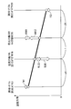
- Each of the differential gears of the conventional power unit is configured by a combination of single planetary type first to third planetary gear mechanisms, and has first to fifth elements capable of transmitting power between each other. is doing. As shown in FIG. 88, these first to fifth elements have their rotational speeds satisfying a collinear relationship, and in the collinear diagram representing the collinear relationship, the rotational speeds of the first to fifth elements are simple. It is configured to line up in this order on one straight line.
- the first planetary gear mechanism includes a first sun gear, a first carrier, and a first ring gear
- the second planetary gear mechanism includes a second sun gear, a second carrier, and a second ring gear.
- the three planetary gear mechanism has a third sun gear, a third carrier, and a third ring gear.
- the conventional power unit is mounted on a four-wheeled vehicle.
- the first element is connected to the first rotating electrical machine
- the second element is the left drive wheel
- the third element is the engine
- the fourth element is
- the fifth element is connected to the right drive wheel and the second rotating electrical machine, respectively.
- the first to fifth elements are configured by combining the three planetary gear mechanisms including the first to third planetary gear mechanisms as described above, so the number of parts is reduced. Increasing the number is unavoidable, and as a result, as in Patent Document 1, the apparatus is increased in size, weight, and manufacturing cost.
- the present invention has been made to solve the above-described problems, and provides a power unit that can be simply configured and can be reduced in size, weight, and manufacturing cost. For the purpose.
- the invention according to claim 1 is directed to two driven parts (left and right) for propelling a transportation system (vehicles VFR, VFF, VAW in the embodiment (hereinafter the same in this section)).
- An electric machine 11 a second energy input / output device (second rotary electric machine 12) capable of inputting / outputting rotational energy
- a first pinion gear P1 (FIGS. 82, 84, pinion gear P1B, FIG.
- pinion gear P1D meshing with each other;
- the second pinion gear P2 (FIG. 78, pinion gear PA, FIG. 82, FIG. 84, pinion gear P2B, FIG. 86 pinion gear P2D) is rotatably supported.
- 76 (FIG. 76, FIG. 78, FIG. 80, carrier member 91, FIG. 82, FIG. 84, carrier member 95, FIG. 86, carrier member 101), a first gear meshing with one of the first and second pinion gears P1, P2.
- first ring gear R1D first ring gear R1D
- the rotational speeds of the four rotating elements comprising the carrier and the first to third gears are a single straight line in the collinear diagram
- Differential gears GSG to GSL configured to satisfy the collinear relationship arranged on the top, and among the four rotating elements, first and second outer rotating elements ( 77, 83, first sun gear S1, second sun gear S2, FIG. 79, carrier member 91, second sun gear S2, FIG. 81, second sun gear S2X, first ring gear R1X, FIG. 85, first sun gear S1, first The two-ring gear R2B, FIG.
- First and second quasi-outer rotating elements (FIG. 77, carrier member 91, first ring gear R1, 79, second ring gear R2A, first ring gear R1, FIG. 81, second ring gear R2X, respectively) located next to the element.
- Carrier member 91, FIG. 83, second ring gear R2B, carrier member 95, FIG. 85, first ring gear R1B, carrier member 95, FIG. 87, second ring gear R2D, first ring gear R1D) are one of the two driven parts. And the other mechanically connected to each other.
- the differential device rotatably supports the first and second pinion gears that mesh with each other, the first and second gears that mesh with one of the first and second pinion gears, It has four rotating elements comprising a third gear meshing with the other of the first and second pinion gears. Further, the rotational speeds of these four rotating elements are in a collinear relationship arranged on a single straight line in the collinear diagram.
- the first and second pinion gears mesh with each other
- the first and second gears are one of the first and second pinion gears
- the third gear is the first and first gears.
- the first and second outer rotating elements respectively located on both outer sides in the collinear diagram are mechanically connected to the first and second energy input / output devices, respectively.
- the first and second quasi-outer rotating elements respectively located next to the second outer rotating element are mechanically connected to one and the other of the two driven parts, respectively.
- the differential gears GS, GSA, GSX, GSB to GSD, and GSF are fourth gears that mesh with the other of the first and second pinion gears P1 and P2.
- the rotational speeds of the five rotating elements including the fourth gear, the carrier, and the first to third gears satisfy the collinear relationship arranged on a single straight line in the collinear diagram.
- first and second outer rotating elements (FIGS. 5, 64, 69, 75, first sun gear S1, second sun gear S2, FIG. 66, first ring gear R1X, second sun gear S2X, Fig. 73
- the rear member 101 and the second sun gear S2D are mechanically coupled to the first and second energy input / output devices, respectively, and the first and second quasi-outer rotating elements (FIGS. 5 and 75, the second ring gear R2, the second 64, carrier member 91, first ring gear R1, FIG. 66, carrier member 91, first sun gear S1X, FIG. 69, first ring gear R1B, second ring gear R2B, FIG. 73, first ring gear R1D, first ring gear R1B, FIG. 1 sun gear S1D) is mechanically connected to one and the other driven parts, respectively.
- the differential device further includes the fourth gear meshing with the other of the first and second pinion gears in addition to the first to third gears described in the description of the invention according to claim 1.
- the rotational speeds of the five rotary elements including the carrier and the first to fourth gears satisfy the collinear relationship arranged on a single straight line in the collinear diagram.
- the rotational speed can be increased by simply combining the two planetary gear mechanisms including the first and second planetary gear mechanisms.
- Five rotating elements that are in a collinear relationship with each other can be easily configured, and the number of components can be reduced, so that the apparatus can be reduced in size, weight, and manufacturing cost.
- the first and second outer rotating elements respectively located on both outer sides in the collinear diagram are mechanically connected to the first and second energy input / output devices, respectively.
- the first and second quasi-outer rotating elements respectively located next to the second outer rotating element are mechanically connected to one and the other of the two driven parts, respectively.
- an energy output device (engine 3) capable of outputting rotational energy and provided separately from the first and second energy input / output devices.
- a central rotating element (FIG. 5, carrier member 13, FIG. 64, second) which is a rotating element other than the first and second outer rotating elements and the first and second quasi-outer rotating elements of the five rotating elements.
- the ring gear R2A, FIG. 66, the second ring gear R2X, FIG. 69, the carrier member 95, FIG. 73, and the second ring gear R2D) are mechanically coupled to the energy output device.
- the first and second outer rotating elements and the central rotating element other than the first and second quasi-outer rotating elements among the five rotating elements can output rotational energy.
- the energy output device is mechanically coupled to the device and is provided separately from the first and second energy input / output devices.
- the rotational energy from the energy output device is transmitted to the two driven parts in addition to the rotational energy from the first and second energy input / output devices, which is necessary for the first and second energy input / output devices. Torque can be reduced, thereby reducing the size of both devices.
- the first gear is provided on the inner periphery of the first pinion gear P1, and the first sun gear S1 that meshes with the first pinion gear P1, and the second
- the first gear is the first sun gear S1
- the second gear is provided on the outer periphery of the first pinion gear P1.
- the second gear is provided on the inner periphery of the pinion gear P2 and meshes with the second pinion gear P2.
- the first ring gear R1 meshes with the first pinion gear P1
- the third gear is provided on the inner periphery of the second pinion gear P2
- the second sun gear S2 (FIG. 76) meshes with the second pinion gear P2.
- One of the second ring gears provided on the outer periphery of the two-pinion gear P2 and meshing with the second pinion gear P2.
- the first and second gears are the first (second) sun gear and the first (second) ring gear that mesh with the first (second) pinion gear, respectively.
- the third gear is one of a second (first) sun gear and a second (first) ring gear that meshes with the second (first) pinion gear.
- ⁇ A and ⁇ A are the first and second lever ratios (torque ratio / speed ratio), and the former ⁇ A is transmitted to the carrier member and the first ring gear with respect to the torque transmitted to the first sun gear.
- the ratio ⁇ A represents the ratio of the torque transmitted to the carrier member and the first ring gear with respect to the torque transmitted to the second sun gear.
- the first and second lever ratios ⁇ A and ⁇ A are expressed by equations (3) and (4) described later, respectively.
- FIG. 88 shows the rotational speed relationship and the torque balance relationship between the various rotary elements in the above-described conventional power device of Patent Document 2.
- A1 and A2 are first and second lever ratios (torque ratio / speed ratio), and the former A1 is the second and fourth through the first element with respect to the torque transmitted to the first element.
- the ratio A2 represents the ratio of torque transmitted to the element, and the latter A2 represents the ratio of the torque transmitted to the second and fourth elements via the fifth element with respect to the torque transmitted to the fifth element.
- both A1 and A2 are set to the same value in order to accurately and easily control the torque distributed from the first and second rotating electrical machines to the left and right drive wheels via the differential. It is preferable.
- Zr1 / Zs1 (Zr2 ⁇ Zr3) / (Zs2 ⁇ Zs3) between the number of teeth of each gear.
- Zr1 is the number of teeth of the first ring gear
- Zs1 is the number of teeth of the first sun gear
- Zr2 is the number of teeth of the second ring gear
- Zr3 is the number of teeth of the third ring gear
- Zs2 is the number of teeth of the second sun gear
- Zs3 is the number of teeth of the third sun gear.
- the present invention for example, from the number of teeth of the first ring gear, the number of teeth of the first sun gear, and the number of teeth of the second sun gear.
- the first and second lever ratios ⁇ A and ⁇ A can be easily set to the same value by setting the total number of three teeth to different values. Thereby, the rotational energy distributed to the first and second driven parts from the first and second energy input / output devices via the differential device can be controlled more appropriately.
- first and second rotating electrical machines 11 and 12 which will be described later, are used as the first and second energy input / output devices, and front and rear output shafts SF, SR, which are described later, are used as two driven parts, respectively.
- front and rear output shafts SF, SR which are described later, are used as two driven parts, respectively.
- other appropriate energy input / output devices and driven parts may be used.
- one and the other of the two driven parts correspond to the first and second quasi-outside rotating elements instead of the first and second sun gears, respectively. Since the carrier (carrier member) and the first ring gear are connected to each other, the following effects can be obtained.
- the meshing radius rs of the first sun gear is relatively small, and the torque transmitted from the first sun gear to the driven portion is applied to the meshing radius rs and the first sun gear. Since it is represented by the product of the acting tangential meshing reaction force fs, a very large meshing reaction force fs acts on the first sun gear as a large torque is transmitted to the driven part. To do. For this reason, the tooth width of the first sun gear must be set to a large value so as to withstand such a meshing reaction force fs, thereby increasing the size of the power unit.
- centrifugal force gp acts on the bearing that supports the first pinion gear (hereinafter referred to as “first pinion bearing”) as the first pinion gear rotates. Further, a relatively large meshing reaction force ps from the first sun gear acts on the first pinion gear as a large torque is transmitted from the first sun gear to the right output shaft. The force ps acts on the first pinion bearing in the same direction as the centrifugal force gp. In FIG. 89, for the sake of convenience, the centrifugal force gp and the meshing reaction force ps are shown only for the first pinion gear located at the lower right of the drawing.
- the first pinion bearing is subjected to a very large resultant force including the centrifugal force gp accompanying the rotation of the first pinion gear and the large meshing reaction force ps from the first sun gear.
- the bearing has to be enlarged in order to ensure sufficient durability. Therefore, this also increases the size of the power unit.
- the meshing radius rr of the first ring gear is relatively large, and the torque transmitted from the first ring gear to the other driven portion acts on the meshing radius rr and the first ring gear. Since it is represented by the product of the meshing reaction force FR, the meshing which acts on the first ring gear as the torque is transmitted to the other driven part as compared with the case of the first sun gear described in FIG. The reaction force FR becomes small. Therefore, the tooth width of the first ring gear can be set to a relatively small value, thereby further reducing the size of the power plant.
- centrifugal force GP acts on the first pinion bearing as the first pinion gear rotates.
- the mesh reaction force PR from the first ring gear acts on the first pinion gear as the torque is transmitted from the first ring gear to one of the rotation shafts.
- the mesh reaction force PR is applied to the first pinion gear. It acts on the bearing in the direction opposite to the centrifugal force GP.
- the centrifugal force GP and the meshing reaction force PR act on the first pinion bearing so as to cancel each other. Therefore, the first sun gear is compared with the case where the first sun gear is connected to the driven portion.
- the pinion bearing can be reduced in size, and this also allows the power unit to be further reduced in size.
- the centrifugal force GP and the meshing reaction force PR are shown only for the first pinion gear located on the right side of the drawing.
- the invention according to claim 5 is the power plant according to claim 2 or 3, wherein the first gear is a first sun gear S1 that is provided on the inner periphery of the first pinion gear P1 and meshes with the first pinion gear P1,
- the second gear is provided on the outer periphery of the first pinion gear P1, and is a first ring gear R1 that meshes with the first pinion gear P1, and the third gear is provided on the inner periphery of the second pinion gear P2, and the second pinion gear P2.
- the second sun gear S2 that meshes with the second pinion gear P2, and the fourth gear is a second ring gear R2 that meshes with the second pinion gear P2 (FIG. 2).
- the first and second gears are the first sun gear and the first ring gear meshing with the first pinion gear
- the third gear is the second sun gear and the second ring gear meshing with the second pinion gear.
- ⁇ and ⁇ in FIG. 5 are the first and second lever ratios (torque ratio / speed ratio), and the former ⁇ is the first and second via the first sun gear with respect to the torque transmitted to the first sun gear. Represents the ratio of torque transmitted to the second ring gear, and the latter ⁇ represents the ratio of torque transmitted to the first and second ring gears via the second sun gear with respect to the torque transmitted to the second sun gear. ing. Further, the first and second lever ratios ⁇ and ⁇ are respectively expressed by equations (1) and (2) described later.
- FIG. 5 shows the first and second rotating electric machines 11 and 12 described later as first and second energy input / output devices, and left and right output shafts SRL and SRR described later as two driven parts.
- first and second energy input / output devices and left and right output shafts SRL and SRR described later as two driven parts.
- other suitable energy input / output devices, driven parts, and energy output devices may be used.
- both gears can be machined with the same specifications that differ only in the twisting direction, so that the productivity is excellent.
- one and the other of the two driven parts correspond to the first and second quasi-outside rotating elements instead of the first and second sun gears, respectively.
- the second and first ring gears are connected to each other. Therefore, similarly to the invention according to claim 4, the tooth width of the first and second ring gears can be set to a relatively small value, and the first pinion bearing can be downsized and the bearing that supports the second pinion gear (hereinafter referred to as the second pinion gear).
- the size of the “second pinion bearing” can be reduced, and the power device can be further reduced in size.
- the second pinion gear includes a first split gear (second pinion gear P2) that meshes with the first pinion gear P1, and a first pinion gear P1 that does not mesh with the first pinion gear P1.
- a double pinion gear comprising a second split gear (pinion gear PA) meshing with the one split gear.
- the first gear is provided on the inner periphery of the first pinion gear P1, and the first sun gear and the second gear meshing with the first pinion gear P1.
- the first gear is the first sun gear
- the second gear is the first sun gear
- the first ring gear is provided on the outer periphery of the pinion gear and meshes with the first pinion gear.
- the third gear is a second sun gear that meshes with the second split gear of the second pinion gear, and a second ring gear that meshes with the second split gear.
- the first gear is the second sun gear S2X meshing with the second split gear of the second pinion gear (FIG. 80)
- the second gear is provided on the outer periphery of the second pinion gear
- the second ring gear R2X meshes with the first split gear of the pinion gear
- the third gear is one of the first sun gear and the first ring gear R1X
- the first gear meshes with the second split gear of the second pinion gear.
- the ring gear is R2A (FIG. 78)
- the second gear is provided on the inner periphery of the second pinion gear and the second pinion gear.
- a second sun gear S2 meshing with the first dividing gear, third gear, and characterized in that one of the first sun gear and the first ring gear R1.
- the differential device having four rotating elements whose rotational speeds are collinear with each other can be appropriately configured by the carrier and the first to third gears, and thus according to claim 1
- the effect by invention can be acquired appropriately.
- the first gear is a second sun gear that meshes with the second split gear of the second pinion gear
- the second gear is a second ring gear that meshes with the first split gear of the second pinion gear
- the third gear is When the first ring gear meshes with the first pinion gear, the relationship between the rotational speeds of the four rotating elements including the second sun gear, the second ring gear, the carrier member (carrier) and the first ring gear is shown in FIG. It is expressed as follows.
- ⁇ I and ⁇ I are the first and second lever ratios (torque ratio / speed ratio), and the former ⁇ I is transmitted to the second ring gear and the carrier member with respect to the torque transmitted to the second sun gear.
- the ratio ⁇ I represents the ratio of the torque transmitted to the second ring gear and the carrier member with respect to the torque transmitted to the first ring gear.
- the first and second lever ratios ⁇ I and ⁇ I are expressed by the following expressions (13) and (14), respectively.
- the total number of teeth consisting of the number of teeth of the second ring gear, the number of teeth of the second sun gear, and the number of teeth of the first ring gear are set to different values.
- the first and second lever ratios ⁇ I and ⁇ I can be easily set to the same value. Thereby, the rotational energy distributed to the first and second driven parts from the first and second energy input / output devices via the differential device can be controlled more appropriately.
- first and second rotating electric machines 11 and 12 described later as first and second energy input / output devices are used, and left and right output shafts SRL and SRR described later are used as two driven parts, respectively.
- left and right output shafts SRL and SRR described later are used as two driven parts, respectively.
- other appropriate energy input / output devices and driven parts may be used.
- the tooth width of the second ring gear can be set to a relatively small value, and the second pinion bearing can be reduced in size. Can be achieved.
- the second pinion gear is not meshed with the first split gear (second pinion gear P2) meshed with the first pinion gear P1 and the first pinion gear P1.
- a second pinion gear (pinion gear PA) that meshes with the first split gear.
- the first gear is provided on the inner periphery of the first pinion gear P1 and is engaged with the first sun gear S1. , S1X
- the second gear is provided on the outer periphery of the first pinion gear P1
- the first ring gears R1 and R1X meshing with the first pinion gear P1
- the third gear is provided on the inner periphery of the second pinion gear.
- a second sun gear S2X that meshes with the second split gear of the second pinion gear, and the second pinion gear When it is one of the second ring gears R2A that is provided on the outer periphery and meshes with the second split gear of the second pinion gear, and the fourth gear is the second sun gear S2X that meshes with the second split gear,
- the second ring gear R2X is provided on the outer periphery of the two-pinion gear and meshes with the first split gear of the second pinion gear (FIG.
- a second sun gear S2 is provided on the inner periphery of the two-pinion gear and meshes with the first split gear of the second pinion gear (FIG. 61).
- the five rotating elements whose rotation speeds are collinear with each other can be appropriately configured by the carrier and the first to fourth gears.
- the effect of the invention according to claim 2 or 3 can be obtained. You can get it properly.
- the first gear is a second ring gear that meshes with the second split gear of the second pinion gear
- the second gear is the second sun gear that meshes with the first split gear of the second pinion gear
- the third and second When the four gears are the first sun gear and the first ring gear that mesh with the first pinion gear, respectively, between the five rotating elements including the first sun gear, the carrier (carrier member), the second ring gear, the first ring gear, and the second sun gear.
- the relationship between the rotational speeds is expressed as shown in FIG.
- ⁇ A and ⁇ A are first and second lever ratios (torque ratio / speed ratio), and the former ⁇ A is transmitted to the carrier member and the first ring gear with respect to the torque transmitted to the first sun gear.
- the ratio ⁇ A represents the ratio of the torque transmitted to the carrier member and the first ring gear with respect to the torque transmitted to the second sun gear.
- the first and second lever ratios ⁇ A and ⁇ A are expressed by equations (3) and (4) described later, respectively.
- the total number of teeth consisting of the number of teeth of the first ring gear, the number of teeth of the first sun gear, and the number of teeth of the second sun gear is made different from each other.
- the first and second lever ratios ⁇ A and ⁇ A can be easily set to the same value. Thereby, the rotational energy distributed to the first and second driven parts from the first and second energy input / output devices via the differential device can be controlled more appropriately.
- FIG. 64 uses first and second rotating electrical machines 11 and 12 described later as first and second energy input / output devices, and front and rear output shafts SF and SR described later as two driven parts, respectively. However, it is a matter of course that other appropriate energy input / output devices and driven parts may be used. Further, the positions of the first and second ring gears in the nomograph are interchanged depending on the setting of the number of teeth of both.
- the first ring gear is connected to the driven portion (rear output shaft SR) instead of the sun gear. Therefore, similarly to the invention according to claim 4, the tooth width of the first ring gear can be set to a relatively small value, and the first pinion bearing can be reduced in size. Can be achieved.
- the first pinion gear is a second split gear that meshes with the first split gear without meshing with the first split gear (first pinion gear P1) and the second pinion gear. It is a double pinion gear composed of split gears (pinion gear P1B, pinion gear P1D), and the second pinion gear does not mesh with the third split gear (second pinion gear P2) that meshes with the first split gear, and with the first and second split gears. And a fourth pinion gear (pinion gears P2B, P2D) meshing with the third split gear.
- the first gear is provided on the inner periphery of the first pinion gear, and the second split gear of the first pinion gear.
- the first sun gear and the first pinion gear that are meshed with each other are arranged on the outer periphery of the first pinion gear and meshed with the second split gear of the first pinion gear.
- the first gear is a first sun gear that meshes with the second split gear of the first pinion gear
- the second gear is provided on the outer periphery of the first pinion gear.
- a first ring gear that meshes with the first split gear of the first pinion gear, and the third gear meshes with the second sun gear that meshes with the fourth split gear of the second pinion gear and the fourth split gear of the second pinion gear.
- a first ring gear which is one of the second ring gears, and the first gear meshes with the second split gear of the first pinion gear.
- the second gear is provided on the inner periphery of the first pinion gear and is the first sun gear S1 meshing with the first split gear of the first pinion gear
- the third gear is the fourth split of the second pinion gear.
- Second ring gear R2B (FIG.
- the second gear is provided on the outer periphery of the second pinion gear and is the second ring gears R2B and R2D meshing with the third split gear of the second pinion gear, and the third gear is the first pinion gear.
- the first sun gear S1 (FIG. 82) meshing with the second split gear and the first ring gear R1D (FIG. 86) meshing with the second split gear.
- the first gear is the second ring gear meshing with the fourth split gear of the second pinion gear
- the second gear is provided on the inner periphery of the second pinion gear and the third split gear of the second pinion gear.
- the third gear is one of the first ring gear that meshes with the second split gear of the first pinion gear and the first sun gear that meshes with the second split gear of the first pinion gear.
- the four rotating elements whose rotational speeds are collinear with each other can be appropriately configured by the carrier and the first to third gears.
- the effect of the invention according to claim 1 can be appropriately achieved.
- the first gear is a first ring gear that meshes with the second split gear of the first pinion gear
- the second gear is the first sun gear that meshes with the first split gear of the first pinion gear
- the third gear is
- the second ring gear meshes with the fourth split gear of the second pinion gear the relationship between the rotational speeds of the four rotating elements including the first sun gear, the first ring gear, the carrier member (carrier), and the second ring gear is It is represented as shown in FIG.
- ⁇ K and ⁇ K are first and second lever ratios (torque ratio / speed ratio), and the former ⁇ K is transmitted to the first ring gear and the carrier member with respect to the torque transmitted to the first sun gear.
- the ratio ⁇ K represents the ratio of the torque transmitted to the first ring gear and the carrier member with respect to the torque transmitted to the second ring gear.
- the first and second lever ratios ⁇ K and ⁇ K are respectively expressed by equations (17) and (18) described later.
- the total number of teeth consisting of the number of teeth of the first ring gear, the number of teeth of the first sun gear, and the number of teeth of the second ring gear are set to different values.
- the first and second lever ratios ⁇ K and ⁇ K can be easily set to the same value. Thereby, the rotational energy distributed to the first and second driven parts from the first and second energy input / output devices via the differential device can be controlled more appropriately.
- first and second rotating electrical machines 11 and 12 which will be described later, are used as the first and second energy input / output devices, and left and right output shafts SRL, SRR, which are described later, are used as two driven parts, respectively.
- first and second rotating electrical machines 11 and 12 which will be described later, are used as the first and second energy input / output devices
- left and right output shafts SRL, SRR which are described later, are used as two driven parts, respectively.
- other appropriate energy input / output devices and driven parts may be used.
- the tooth width of the first ring gear can be set to a relatively small value, and the first pinion bearing can be reduced in size. Can be achieved.
- the invention according to claim 9 is the power plant according to claim 2 or 3, wherein the first pinion gear meshes with the first split gear without meshing with the first split gear (first pinion gear P1) and the second pinion gear. It is a double pinion gear comprising a second split gear (pinion gears P1B, P1D). The second pinion gear meshes with a third split gear (second pinion gear P2) that meshes with the first split gear and with the first and second split gears. And a second pinion gear comprising a fourth split gear (pinion gears P2B, P2D) meshing with the third split gear, and the first gear is provided on the inner periphery of the first pinion gear and the second split gear of the first pinion gear.
- the first sun gear S1 that meshes with the outer periphery of the first pinion gear and the second division of the first pinion gear
- One of the first ring gears R1B, R1D meshing with the gear, and the second gear is provided on the outer periphery of the first pinion gear when the first gear is the first sun gear S1 meshing with the second split gear of the first pinion gear.
- the first ring gear R1B meshes with the first split gear of the first pinion gear (FIG. 67), and is provided on the inner periphery of the first pinion gear when the first gear is the first ring gears R1B, R1D meshed with the second split gear.
- first sun gears S1 and S1D meshing with the first split gear of the first pinion gear (FIGS. 70 and 71), and the third gear is provided on the inner periphery of the second pinion gear and the second pinion gear
- the second sun gears S2 and S2D that mesh with the four-split gear and the second pinion gear are provided on the outer periphery of the second pinion gear.
- the second ring gears R2B and R2D are provided on the outer periphery and mesh with the third split gear of the second pinion gear (FIGS. 67 and 71)
- the third gear is the second ring gear R2B meshed with the fourth split gear
- the second sun gear S2 is provided on the inner periphery of the second pinion gear and meshes with the third split gear of the second pinion gear (FIG. 70).
- the five rotating elements whose rotation speeds are collinear with each other can be appropriately configured by the carrier and the first to fourth gears, and as a result, the effect of the invention according to claim 2 or 3 Can be obtained appropriately.
- the first and third gears are the first sun gear and the first ring gear that mesh with the second and first split gears of the first pinion gear, respectively
- the second and fourth gears are the fourth pinion gear of the second pinion gear.
- the second sun gear and the second ring gear meshing with the third split gear, respectively, the rotation between the five rotating elements including the first sun gear, the first ring gear, the carrier (carrier member), the second ring gear, and the second sun gear.
- the relationship of the numbers is expressed as shown in FIG.
- ⁇ B and ⁇ B are the first and second lever ratios (torque ratio / speed ratio), and the former ⁇ B is transmitted to the first and second ring gears with respect to the torque transmitted to the second sun gear.
- the latter ⁇ B represents the ratio of the torque transmitted to the first and second ring gears with respect to the torque transmitted to the first sun gear.
- the first and second lever ratios ⁇ B and ⁇ B are expressed by equations (7) and (8) described later, respectively.
- both gears can be machined with the same specifications that differ only in the twisting direction, so that the productivity is excellent.
- first and second rotating electrical machines 11 and 12 which will be described later, are used as the first and second energy input / output devices, and left and right output shafts SRL, SRR, which will be described later, are used as two driven parts, respectively.
- SRL, SRR left and right output shafts SRL, SRR, which will be described later, are used as two driven parts, respectively.
- other appropriate energy input / output devices and driven parts may be used.
- one and the other of the two driven parts correspond to the first and second quasi-outside rotating elements instead of the first and second sun gears, respectively.
- the second and first ring gears are connected to each other. Therefore, like the invention according to claim 4, the tooth widths of the first and second ring gears can be set to a relatively small value, and the first and second pinion bearings can be reduced in size, and consequently Further reduction in size of the power unit can be achieved.
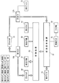
- FIG. 1 is a diagram schematically showing a power unit according to a first embodiment of the present invention together with a vehicle to which the power unit is applied. It is a skeleton figure which shows the power plant etc. of FIG.
- FIG. 3 is a skeleton diagram in plan view of a first pinion gear, a second pinion gear, and a carrier member of the differential device of FIG. 2. It is a block diagram which shows ECU etc. of the power plant of FIG.
- FIG. 2 is a collinear diagram showing a rotational speed relationship and a torque balance relationship between various types of rotary elements in the power plant of FIG. 1 when the vehicle is traveling straight ahead and in a travel state other than decelerating travel.
- FIG. 2 is a collinear diagram showing a rotational speed relationship and a torque balance relationship between various types of rotary elements in the power plant shown in FIG. 1 when the vehicle is traveling straight ahead and during deceleration traveling.
- FIG. 8 is a collinear diagram illustrating a rotational speed relationship and a torque balance relationship between various types of rotary elements in the power plant shown in FIG. 1 during a third torque distribution control for increasing the right yaw moment.
- FIG. 8 is a collinear diagram illustrating a rotational speed relationship and a torque balance relationship between various types of rotary elements in the power plant shown in FIG. 1 during a third torque distribution control for reducing the right yaw moment. It is a skeleton figure which shows the power plant etc.
- FIG. 10 A collinear chart showing a rotational speed relationship and a torque balance relationship between various types of rotary elements of the power plant shown in FIG. 9, during the first torque distribution control for increasing the right yaw moment.
- FIG. 10 A collinear chart showing a rotational speed relationship and a torque balance relationship between various types of rotary elements of the power plant shown in FIG. 9, during the second torque distribution control for increasing the right yaw moment.
- FIG. 10 A collinear chart showing a rotational speed relationship and a torque balance relationship between various types of rotary elements of the power plant shown in FIG. 9, during first torque distribution control for reducing the right yaw moment.
- FIG. 10 A collinear chart showing a rotational speed relationship and a torque balance relationship between various types of rotary elements of the power plant shown in FIG. 9, during first torque distribution control for reducing the right yaw moment.
- FIG. 10 A collinear chart showing a rotational speed relationship and a torque balance relationship between various types of rotary elements of the power plant shown in FIG. 9, during second torque distribution control for reducing the right yaw moment.
- FIG. 10 A collinear chart showing a rotational speed relationship and a torque balance relationship between various types of rotary elements in the power plant shown in FIG. 9, during differential limiting control of the left and right output shafts. It is a skeleton figure which shows the power plant etc. by 3rd Embodiment of this invention. It is a block diagram which shows ECU etc. of the power plant of FIG. FIG. 16 shows the rotational speed relationship and the torque balance relationship between the various rotary elements in the power plant shown in FIG.
- FIG. 17 A collinear chart showing a rotational speed relationship between various types of rotary elements of the power plant shown in FIG. 16 in the MOT drive mode. It is a skeleton figure which shows the power plant etc. by 4th Embodiment of this invention. It is a block diagram which shows ECU etc. of the power plant of FIG. It is a figure which shows the connection relation between the various rotary elements in the power plant of FIG. It is a figure which shows the transmission condition of the torque between the various rotary elements in the power plant of FIG. 20 about 1 MOT drive mode.
- FIG. 25 A diagram showing a state of transmission of torque between various types of rotary elements in the power plant shown in FIG. 20 for operations different from those in FIG. 24 during torque distribution control in the 1MOT drive mode. It is a figure which shows the transmission condition of the torque between the various rotary elements in the power plant of FIG. 20 about 2 MOT drive mode. It is a figure which shows the transmission condition of the torque between the various rotary elements in the power plant of FIG. 20 during the torque distribution control in 2MOT drive mode. It is a figure which shows the transmission condition of the torque between the various rotary elements in the power plant of FIG.
- FIG. 30 is a diagram showing a connection relationship between various types of rotary elements in the power plant shown in FIG. 29.
- FIG. 30 is a diagram showing a state of transmission of torque between various types of rotary elements in the power plant shown in FIG. 29 in a 2MOT drive mode.
- FIG. 30 A diagram showing how torque is transmitted between various types of rotary elements in the power plant shown in FIG. 29 during torque distribution control in the 2MOT drive mode. It is a figure which shows the transmission condition of the torque between the various rotary elements in the power plant of FIG. 29 about the operation
- FIG. 30 A diagram showing a state of transmission of torque between various types of rotary elements in the power plant shown in FIG.
- FIG. 39 A collinear chart showing a rotational speed relationship and a torque balance relationship between various types of rotary elements of the power plant shown in FIG. 38, as to during a MOT transmission mode.
- FIG. 39 A collinear chart showing a rotational speed relationship and a torque balance relationship between various types of rotary elements of the power plant shown in FIG. 38, as to during the ECVT mode.
- FIG. 39 A collinear chart showing a rotational speed relationship and a torque balance relationship between various types of rotary elements of the power plant shown in FIG.
- FIG. 46 A diagram showing a state of transmission of torque between various types of rotary elements in the power plant shown in FIG. 38, regarding an operation different from that in FIG. 45 during torque distribution control in the 1MOT drive mode. It is a figure which shows the transmission condition of the torque between the various rotary elements in the power plant of FIG.
- FIG. 58 is a skeleton diagram showing the power unit and the like of FIG. 57. It is a block diagram which shows ECU etc. of the power plant of FIG. It is a skeleton figure which shows the power plant etc. by 8th Embodiment of this invention. It is a skeleton figure showing a power unit etc. by a 9th embodiment of the present invention. It is a figure which shows schematically the power plant of FIG. 61 with the vehicle to which this is applied.
- FIG. 62 is a skeleton diagram of the first pinion gear, the second pinion gear, and the carrier member of the differential device of FIG.
- FIG. 62 A collinear chart showing a rotational speed relationship and a torque balance relationship between various types of rotary elements of the power plant shown in FIG. 61. It is a skeleton figure which shows the power plant etc. by 10th Embodiment of this invention.
- FIG. 66 A collinear chart showing a rotational speed relationship and a torque balance relationship between various types of rotary elements of the power plant shown in FIG. 65. It is a skeleton figure which shows the power plant etc. by 11th Embodiment of this invention.
- FIG. 68 is a skeleton diagram of the first pinion gear, the second pinion gear, and the carrier member of the differential device of FIG. 67 viewed in plan.
- FIG. 62 A collinear chart showing a rotational speed relationship and a torque balance relationship between various types of rotary elements of the power plant shown in FIG. 61. It is a skeleton figure which shows the power plant etc. by 10th Embodiment of this invention.
- FIG. 66 A colline
- FIG. 68 A collinear chart showing a rotational speed relationship and a torque balance relationship between various types of rotary elements of the power plant shown in FIG. 67. It is a skeleton figure which shows the power plant etc. by 12th Embodiment of this invention. It is a skeleton figure which shows the power plant etc. by 13th Embodiment of this invention.
- FIG. 72 is a skeleton diagram of the first pinion gear, the second pinion gear, and the carrier member of the differential device of FIG. 71 viewed in plan.
- FIG. 72 A collinear chart showing a rotational speed relationship and a torque balance relationship between various types of rotary elements of the power plant shown in FIG. 71. It is a skeleton figure which shows the power plant etc.
- FIG. 75 A collinear chart showing a rotational speed relationship and a torque balance relationship between various types of rotary elements of the power plant shown in FIG. 74. It is a skeleton figure showing a power unit etc. by a 15th embodiment of the present invention.
- FIG. 77 A collinear chart showing a rotational speed relationship and a torque balance relationship between various types of rotary elements of the power plant shown in FIG. 76. It is a skeleton figure which shows the power plant etc. by 16th Embodiment of this invention.
- FIG. 79 A collinear chart showing a rotational speed relationship and a torque balance relationship between various types of rotary elements of the power plant shown in FIG. 78.
- FIG. 83 A collinear chart showing a rotational speed relationship and a torque balance relationship between various types of rotary elements of the power plant shown in FIG. 80. It is a skeleton figure showing a power unit etc. by an 18th embodiment of the present invention.
- FIG. 83 A collinear chart showing a rotational speed relationship and a torque balance relationship between various types of rotary elements of the power plant shown in FIG. 82. It is a skeleton figure showing a power unit etc. by a 19th embodiment of the present invention.
- FIG. 85 A collinear chart showing a rotational speed relationship and a torque balance relationship between various types of rotary elements of the power plant shown in FIG.
- FIG. 87 A collinear chart showing a rotational speed relationship and a torque balance relationship between various types of rotary elements of the power plant shown in FIG. 86. It is a collinear diagram which shows the relationship of the rotation speed between the various rotation elements in the conventional differential gear. It is a figure for demonstrating the effect of this invention. It is a figure different from FIG. 89 for demonstrating the effect of this invention.
- the power plant according to the first embodiment shown in FIGS. 1 and 2 is for driving left and right output shafts SRL and SRR of a four-wheel vehicle VFR.
- These left and right output shafts SRL and SRR are arranged coaxially with each other and are connected to left and right rear wheels WRL and WRR, respectively.
- the power plant includes an internal combustion engine (hereinafter referred to as “engine”) 3 as a power source and a first transmission 4 for shifting the power of the engine 3, both of which are provided at the front of the vehicle VFR.
- engine 3 is a gasoline engine, and a crankshaft (not shown) is connected to an input shaft (not shown) of the first transmission 4.
- the first transmission 4 is a stepped automatic transmission that shifts the power of the engine 3 transmitted to the input shaft and outputs it to the transmission output shaft (not shown).
- the transmission output shaft is connected to a propeller shaft S extending in the front-rear direction, and a gear 5 (see FIG. 2) is connected to the propeller shaft S.
- the power unit also includes a distribution device DS1 for controlling the power distributed to the left and right output shafts SRL and SRR.
- the distribution device DS1 includes a differential device GS, a first rotating electrical machine 11, a second rotating electrical machine 12, and the like, and is disposed at the rear part of the vehicle VFR.
- the differential GS is for transmitting power between the engine 3, the first and second rotating electrical machines 11 and 12, and the left and right output shafts SRL and SRR.
- the differential device GS is obtained by combining two single planetary type first and second planetary gear mechanisms, sharing a carrier, and meshing the pinion gears of both planetary gear mechanisms.
- the differential device GS includes a carrier member 13, a first sun gear S1, a first pinion gear P1, a first ring gear R1, a second sun gear S2, a second pinion gear P2, and a second ring gear R2.
- the first sun gear S1, the first pinion gear P1, the first ring gear R1, and the carrier member 13 constitute the first planetary gear mechanism
- the second sun gear S2, the second pinion gear P2, the second ring gear R2, and the carrier member. 13 constitutes the second planetary gear mechanism.
- the differential device GS is disposed coaxially with the left and right output shafts SRL and SRR, and is positioned between the left rear wheel WRL and the right rear wheel WRR.
- the carrier member 13 includes a doughnut-shaped first base portion 13a and a second base portion 13b, and four first support shafts 13c and a second support shaft 13d provided integrally with the base portions 13a and 13b (both only two). (Illustrated).
- the carrier member 13 is rotatably supported by a bearing (not shown), and a first rotating shaft 14 and a third rotating shaft 16 to be described later are relatively rotatably disposed inside the carrier member 13. Yes.
- the first and second base portions 13a and 13b are arranged coaxially with the left and right output shafts SRL and SRR, and face each other in the axial direction.
- the second base portion 13b is disposed on the right rear wheel WRR side with respect to the first base portion 13a, and a ring-shaped gear 13e is integrally provided on the second base portion 13b.
- the gear 13e meshes with the gear 5 described above.
- the first and second support shafts 13c and 13d are provided between the first and second base portions 13a and 13b and extend in the axial direction of the left and right output shafts SRL and SRR. Further, the first and second support shafts 13c and 13d are alternately arranged at equal intervals in the circumferential direction of the first base portion 13a.
- the first sun gear S1, the first pinion gear P1, and the first ring gear R1 are arranged in this order from the inside in the radial direction.
- the first sun gear S ⁇ b> 1 is integrally attached to one end of the hollow first rotating shaft 14.
- the first rotating shaft 14 is rotatably supported by a bearing (not shown), and a first rotor 11b described later of the first rotating electrical machine 11 is integrally attached to the other end of the first rotating shaft 14. It has been. Accordingly, the first sun gear S1 is rotatable integrally with the first rotor 11b. Further, the right output shaft SRR is relatively rotatably disposed inside the first rotation shaft 14.
- the number of first pinion gears P1 is the same value 4 (only two are shown) as the first support shaft 13c of the carrier member 13 described above.
- Each first pinion gear P1 is rotatably supported by a first support shaft 13c via a bearing (not shown), and meshes with both the first sun gear S1 and the first ring gear R1.
- the number of the first pinion gears P1 and the first support shafts 13c is not limited to the value 4, and is arbitrary.
- the first ring gear R1 is connected to the right output shaft SRR via a hollow second rotating shaft 15 and a flange, and is rotatable together with the right output shaft SRR.
- the second sun gear S2, the second pinion gear P2, and the second ring gear R2 are arranged in this order from the inside in the radial direction, and these gear sets are the first sun gear S1, the first pinion gear P1, and the first ring gear described above. It is arranged between the gear set consisting of R1 and the right rear wheel WRR.
- the second sun gear S ⁇ b> 2 is integrally attached to one end portion of the hollow third rotating shaft 16.
- the third rotating shaft 16 is rotatably supported by a bearing (not shown), and a second rotor 12b (described later) of the second rotating electrical machine 12 is integrally attached to the other end portion of the third rotating shaft 16. It has been.
- the second sun gear S2 is rotatable integrally with the second rotor 12b.
- the first rotary shaft 14 described above is relatively rotatably disposed inside the third rotary shaft 16.
- the number of second pinion gears P2 is the same value 4 (only two are shown) as the above-described second support shaft 13d of the carrier member 13.
- Each second pinion gear P2 is rotatably supported by a second support shaft 13d via a bearing (not shown) and meshes with both the second sun gear S2 and the second ring gear R2.
- the second pinion gear P2 is disposed so as to partially overlap the first pinion gear P1 in the circumferential direction of the second sun gear S2, and meshes with the first pinion gear P1.
- the number of the second pinion gear P2 and the second support shaft 13d is not limited to the value 4, and is arbitrary. In FIG. 3, for the sake of convenience, the first and second sun gears S1, S2 and the first and second ring gears R1, R2 are omitted.
- the second ring gear R2 is connected to the left output shaft SRL via a hollow fourth rotating shaft 17 and a flange, and is rotatable integrally with the left output shaft SRL. Inside the fourth rotation shaft 17, the carrier member 13 and the second rotation shaft 15 are relatively rotatably arranged.
- first pinion gear P1 and the second pinion gear P2 have the same diameter and the same number of teeth. Accordingly, the diameter of the first sun gear S1 and the diameter of the second sun gear S2, and the diameter of the first ring gear R1 and the diameter of the second ring gear R2 are set to the same value.
- the first pinion gear P1 and the second pinion gear P2 have the same tooth profile and the same tooth width. As described above, the diameter, the number of teeth, the tooth profile, and the tooth width of the first and second pinion gears P1 and P2 are the same, that is, the specifications of both gears P1 and P2 are set to be the same. ing.
- the first rotating electrical machine 11 is an AC motor, and includes a first stator 11a composed of a plurality of iron cores and coils, and a first rotor 11b composed of a plurality of magnets.
- the first rotating electrical machine 11 is disposed coaxially with the left and right output shafts SRL and SRR, and is located between the differential gear GS and the right rear wheel WRR.
- the first stator 11a is fixed to a stationary case CA.
- the first rotor 11b is disposed so as to face the first stator 11a, and is rotatable integrally with the first sun gear S1 as described above.
- the first rotating electrical machine 11 when electric power is supplied to the first stator 11a, the supplied electric power is converted into motive power and output to the first rotor 11b.
- this power is converted into electric power (power generation) and output to the first stator 11a.
- the first stator 11 a is electrically connected to a chargeable / dischargeable battery 23 via a first power drive unit (hereinafter referred to as “first PDU”) 21. Can be exchanged.
- the first PDU 21 is configured by an electric circuit such as an inverter. As shown in FIG. 4, an ECU 2 described later is electrically connected to the first PDU 21.
- the ECU 2 controls the first PDU 21 to control the power supplied to the first stator 11a, the power generated by the first stator 11a, and the rotation speed of the first rotor 11b.
- the second rotating electrical machine 12 is an AC motor, like the first rotating electrical machine 11, and includes a second stator 12a and a second rotor 12b.
- the second rotating electrical machine 12 is disposed coaxially with the left and right output shafts SRL and SRR, and is located between the first rotating electrical machine 11 and the differential device GS.
- the second stator 12a and the second rotor 12b are configured similarly to the first stator 11a and the first rotor 11b, respectively. Further, as described above, the second rotor 12b is rotatable integrally with the second sun gear S2.
- the second rotating electrical machine 12 can convert the electric power supplied to the second stator 12a into motive power and output it to the second rotor 12b, and is input to the second rotor 12b. Power can be converted into electric power and output to the second stator 12a.
- the second stator 12 a is electrically connected to the battery 23 via a second power drive unit (hereinafter referred to as “second PDU”) 22, and can transmit and receive electrical energy to and from the battery 23.
- second PDU 22 is configured by an electric circuit such as an inverter, and the ECU 2 is electrically connected to the second PDU 22.
- the ECU 2 controls the second PDU 22 to control the power supplied to the second stator 12a, the power generated by the second stator 12a, and the rotation speed of the second rotor 12b.
- the differential gear GS since the differential gear GS is configured as described above, the first sun gear S1, the second ring gear R2, the carrier member 13, the first ring gear R1 and the second sun gear S2 are mutually connected. Power can be transmitted between them, and their rotational speeds are collinear with each other.
- the collinear relationship is a relationship in which the respective rotational speeds are arranged on a single straight line in the collinear diagram.
- the first sun gear S1 when the first sun gear S1 is rotated forward with the carrier member 13 fixed, the first ring gear R1 and the second sun gear S2 are rotated in reverse and the second ring gear R2 is rotated forward.
- the rotation speed of the first sun gear S1 is higher than that of the second ring gear R2, and the rotation speed of the second sun gear S2 is lower than that of the first ring gear R1.
- the first sun gear S1, the second ring gear R2 the carrier member 13, the first ring gear R1 and the second sun gear S2 are arranged in this order.
- the rotation speed of the first sun gear S1 and the first rotor 11b are equal to each other.
- the second ring gear R2 is connected to the left output shaft SRL via the fourth rotating shaft 17 and the flange, the rotational speed of the second ring gear R2 and the rotational speed of the left output shaft SRL are equal to each other.
- the gear 13e of the carrier member 13 is engaged with the gear 5 connected to the transmission output shaft of the first transmission 4, if the shift by the gear 13e and the gear 5 is ignored, the carrier member 13 The rotational speed and the rotational speed of the transmission output shaft are equal to each other.
- the rotational speed of the first ring gear R1 and the rotational speed of the right output shaft SRR are equal to each other.
- the second sun gear S2 and the second rotor 12b are connected to each other via the third rotating shaft 16, the rotational speed of the second sun gear S2 and the rotational speed of the second rotor 12b are equal to each other.
- the relationship between the rotational speeds of the various rotary elements in the power plant is expressed as a collinear chart shown in FIG. 5, for example.
- the distance from the horizontal line indicating value 0 to the white circle on the vertical line corresponds to the number of rotations of each rotating element.
- the left and right output shafts SRL and SRR can be differentially rotated with respect to each other.
- ⁇ and ⁇ in FIG. 5 are the first lever ratio and the second lever ratio (torque ratio / speed ratio), respectively, and are expressed by the following equations (1) and (2).
- ⁇ ⁇ ZR2 (ZR1-ZS2) ⁇ / ⁇ ZS2 (ZR2 + ZR1) ⁇ (2)
- ZR1 is the number of teeth of the first ring gear R1
- ZR2 is the number of teeth of the second ring gear R2
- ZS1 is the number of teeth of the first sun gear S1
- ZS2 is the number of teeth of the second sun gear S2.
- the number of teeth ZR1 of the first ring gear R1, the number of teeth ZR2 of the second ring gear R2, the number of teeth ZS1 of the first sun gear S1, and the number of teeth ZS2 of the second sun gear S2 (hereinafter “number of teeth of each gear”).
- number of teeth of each gear Is set as follows. That is, on the condition that one of the first and second rotors 11b, 12b does not reverse within a range in which the differential rotation of the left and right rear wheels WRL, WRR is possible, the first and second lever ratios ⁇ , ⁇ are relatively
- the number of teeth of each gear is set so as to be a large value.
- the number of teeth ZR1, ZR2 of the first and second ring gears R1, R2, the number of teeth ZS1, ZS2 of the first and second sun gears S1, S2, and the number of teeth of the first and second pinion gears P1, P2 is set to the same value.
- the first and second lever ratios ⁇ and ⁇ are set to the same value.
- the distance from the carrier member 13 to the left output shaft SRL and the distance from the carrier member 13 to the right output shaft SRR in the alignment chart (FIG. 5) are equal to each other.
- the ECU 2 detects from the steering angle sensor 31 a detection signal representing the steering angle ⁇ of the steering wheel (not shown) of the vehicle VFR, and detects from the vehicle speed sensor 32 a vehicle speed VP of the vehicle VFR.
- a detection signal representing an operation amount (hereinafter referred to as “accelerator opening”) AP of an accelerator pedal (not shown) of the vehicle VFR is input from the accelerator opening sensor 33.
- a detection signal representing a current / voltage value input / output to / from the battery 23 is input from the current / voltage sensor 34 to the ECU 2.
- the ECU 2 calculates the state of charge of the battery 23 based on the detection signal from the current / voltage sensor 34.
- the ECU 2 is composed of a microcomputer including an I / O interface, CPU, RAM, ROM, and the like.
- the ECU 2 controls the first and second rotating electrical machines 11 and 12 according to the control program stored in the ROM in accordance with the detection signals from the various sensors 31 to 34 described above. As a result, various operations of the distribution device DS1 are performed.
- the operation of the distribution device DS1 when the vehicle VFR is traveling straight and when turning left and right will be described.
- FIG. 5 shows the rotational speed relationship and the torque balance relationship between the various rotary elements in this case.
- TM1 and TM2 are output torques (hereinafter referred to as “first motor output torques” respectively) generated in the first and second rotors 11b and 12b in accordance with the power running in the first and second rotating electric machines 11 and 12, respectively.
- first motor output torques (hereinafter referred to as “first motor output torques” respectively) generated in the first and second rotors 11b and 12b in accordance with the power running in the first and second rotating electric machines 11 and 12, respectively.
- RLM1 and RRM1 are reaction force torques acting on the left output shaft SRL and the right output shaft SRR in accordance with powering in the first rotating electrical machine 11
- RLM2 and RRM2 are respectively in the second rotating electrical machine 12. This is a reaction torque that acts on the left output shaft SRL and the right output shaft SRR along with the power running.
- TE is a torque transmitted from the engine 3 to the carrier member 13 via the first transmission 4 (hereinafter referred to as “engine torque after shifting”)
- RLE and RRE are engines after shifting to the carrier member 13. This is the reaction torque that acts on the left output shaft SFL and the right output shaft SFR, respectively, with the transmission of the torque TE.
- the torque transmitted to the left output shaft SRL (hereinafter referred to as “left output shaft transmission torque”) is represented by RLE + RLM1 ⁇ RLM2 (RLM1> RLM2), and torque transmitted to the right output shaft SRR (hereinafter “ The right output shaft transmission torque) is expressed by RRE + RRM2-RRM1 (RRM2> RRM1), and the left and right output shafts SRL, SRR are driven in the forward direction together with the left and right rear wheels WRL, WRR.
- RRE + RRM2-RRM1 RRM2> RRM1
- the distribution ratio of the torque distributed to the SRR is 1: 1 and is equal to each other. Further, the power supplied to the first and second stators 11a and 12a is controlled so that the left and right output shaft transmission torques have the same required torque. This required torque is calculated by searching a predetermined map (not shown) according to the detected accelerator pedal opening AP.
- RLM1-RLM2 of the left output shaft transmission torque is expressed by TM1 ⁇ ( ⁇ + 1) ⁇ TM2 ⁇ ⁇
- RRM2-RRM1 of the right output shaft transmission torque is TM2 ⁇ ( ⁇ + 1) ⁇ TM1.
- X ⁇ the first lever ratio ⁇ is the ratio of the torque transmitted to the left and right output shafts SRL and SRR from the first rotating electrical machine 11 via the differential device GS with respect to the first motor output torque TM1. Represents the ratio.
- the second lever ratio ⁇ represents the ratio of torque transmitted from the second rotating electrical machine 12 to the left and right output shafts SRL and SRR via the differential device GS with respect to the second motor output torque TM2.
- first and second lever ratios ⁇ and ⁇ are set to the same value as described above, only the first and second motor output torques TM1 and TM2 are controlled to the same magnitude.
- the torque distributed from the first and second rotating electric machines 11 and 12 to the left and right output shafts SRL and SRR can be accurately and easily controlled to the same magnitude.
- the execution conditions for executing the power running of the first and second rotating electrical machines 11 and 12 described above are, for example, during the assisting of the engine 3 by the first and second rotating electrical machines 11 and 12 (hereinafter “motor assisting”). Or the vehicle VFR is being driven only by the first and second rotating electrical machines 11 and 12 without using the engine 3 (hereinafter referred to as “EV traveling”), and the calculated charging state of the battery 23 Is greater than the lower limit. In this case, the fact that the state of charge of the battery 23 is larger than the lower limit value means that the battery 23 can be discharged.
- FIG. 5 shows the rotational speed relationship and the torque balance relationship between the various rotary elements during the motor assist. Since the engine 3 is stopped during the EV traveling, Torque TE, reaction force torque RLE, and reaction force torque RRE are not generated.
- FIG. 6 shows the rotational speed relationship and the torque balance relationship between the various types of rotary elements in this case.
- TG1 and TG2 are braking torques (hereinafter referred to as “first motor braking torques” respectively) generated in the first and second rotors 11b and 12b due to regeneration in the first and second rotating electric machines 11 and 12, respectively. "Second motor braking torque”).
- RLG1 and RRG1 are reaction torques acting on the left output shaft SRL and the right output shaft SRR as the first rotating electrical machine 11 is regenerated, and RLG2 and RRG2 are respectively applied to the second rotating electrical machine 12. This is the reaction force torque that acts on the left output shaft SRL and the right output shaft SRR with regeneration.
- the left output shaft transmission torque is represented by ⁇ RLG1 + RLG2 (RLG1> RLG2)
- the right output shaft transmission torque is represented by ⁇ RRG2 + RRG1 (RRG2> RRG1)
- Torque acts and the vehicle VFR is decelerated. Further, the electric power regenerated by the first and second rotating electrical machines 11 and 12 is controlled so that the braking torques acting on the left and right output shafts SRL and SRR are the same.
- -RLG1 + RLG2 is represented by -TG1 ⁇ ( ⁇ + 1) + TG2 ⁇ ⁇
- -RRG2 + RRG1 is -TG2 ⁇ ( ⁇ + 1) + TG1 ⁇ ⁇ . It is represented by As described above, the first and second lever ratios ⁇ and ⁇ are set to the same value, whereby the torque ratio of the torque transmitted from the first rotating electrical machine 11 to the left and right output shafts SRL and SRR, The torque ratio of the torque transmitted from the second rotating electrical machine 12 to the left and right output shafts SRL and SRR is set to the same value.
- the braking torque distributed from the first and second rotating electrical machines 11 and 12 to the left and right output shafts SRL and SRR can be obtained simply by controlling the first and second motor braking torques TG1 and TG2 to the same magnitude. It is possible to control to the same size with high accuracy and easily.
- the execution condition for executing the regeneration of the first and second rotating electrical machines 11 and 12 described above is, for example, a condition that the state of charge of the battery 23 is smaller than the upper limit value.
- the fact that the state of charge of the battery 23 is smaller than the upper limit value indicates that the battery 23 can be charged.
- torque distribution control for increasing the right yaw moment is executed to increase the clockwise yaw moment that turns the vehicle VFR to the right (hereinafter referred to as “right yaw moment”).
- first to fourth torque distribution controls are prepared.
- the first to fourth torque distribution controls for increasing the right yaw moment will be described in order.
- both the first and second rotating electrical machines 11 and 12 perform power running, and the first motor output torque TM1 is larger than the second motor output torque TM2. And the electric power supplied to 2nd stator 11a, 12a is controlled.
- the electric power supplied to the first and second stators 11a and 12a is controlled according to the detected steering angle ⁇ , vehicle speed VP, and accelerator pedal opening AP.
- the execution condition for executing the first torque distribution control for increasing the right yaw moment is, for example, during motor assist (while assisting the engine 3 by the first and second rotating electrical machines 11 and 12) or during EV travel ( This is a condition that the vehicle VFR is being driven only by the first and second rotating electrical machines 11 and 12 and the state of charge of the battery 23 is larger than the lower limit value.
- both the first and second rotating electric machines 11 and 12 perform regeneration, and the battery 23 is charged with the electric power regenerated by both the rotating electric machines 11 and 12.
- the electric power regenerated by the first and second rotating electrical machines 11 and 12 is controlled so that the second motor braking torque TG2 is larger than the first motor braking torque TG1.
- the braking torque acting on the right output shaft SRR becomes larger than that of the left output shaft SRL.
- the right yaw moment of the vehicle VFR increases.
- the electric power regenerated by the first and second rotating electrical machines 11 and 12 is controlled according to the steering angle ⁇ , the vehicle speed VP, and the like.
- the execution condition for executing the second torque distribution control for increasing the right yaw moment is, for example, a condition that the vehicle VFR is traveling at a reduced speed and the state of charge of the battery 23 is smaller than the upper limit value.
- FIG. 7 shows the rotational speed relationship and the torque balance relationship between the various rotary elements in this case.
- TM ⁇ b> 1 in FIG. 7 is the first motor output torque
- RLM ⁇ b> 1 and RRM ⁇ b> 1 are respectively the left output shaft SRL and the right output shaft SRR with the power running in the first rotating electrical machine 11. It is the reaction force torque acting on.
- TE is the engine torque after the shift
- RLE and RRE are reaction torques acting on the left output shaft SFL and the right output shaft SFR, respectively, when the post-shift engine torque TE is transmitted to the carrier member 13.
- TG2 in FIG. 7 is the second motor braking torque
- RLG2 and RRG2 are respectively associated with the left output shaft SRL and the right output in accordance with regeneration at the second rotating electrical machine 12. This is the reaction torque acting on the shaft SRR.
- the left output shaft transmission torque is represented by RLE + RLM1 + RLG2
- the right output shaft transmission torque is represented by RRE- (RRM1 + RRG2).
- the driving torque acts on the left output shaft SRL
- the braking torque acts on the right output shaft SRR.
- the right yaw moment of the vehicle VFR increases.
- the power supplied to the first stator 11a and the power regenerated by the second rotating electrical machine 12 are controlled according to the steering angle ⁇ , the vehicle speed VP, and the accelerator pedal opening AP.
- RLM1 + RLG2 of the left output shaft transmission torque is represented by TM1 ⁇ ( ⁇ + 1) + TG2 ⁇ ⁇
- ⁇ (RRM2 + RRM1) of the right output shaft transmission torque is ⁇ ⁇ TG2 ⁇ ( ⁇ + 1) + TM1 ⁇ ⁇ . Since the first and second lever ratios ⁇ and ⁇ are set to the same value, left and right from the first and second rotating electrical machines 11 and 12 via the first motor output torque TM1 and the second motor braking torque TG2. The torque distributed to the output shafts SRL and SRR can be accurately and easily controlled.
- the execution condition for executing the third torque distribution control for increasing the right yaw moment is, for example, the following first increase condition or second increase condition.
- First increasing condition The vehicle VFR is being driven by the engine 3 and the state of charge of the battery 23 is greater than or equal to the upper limit value.
- Second increasing condition The vehicle VFR is being driven by the engine 3, the state of charge is smaller than the upper limit value, and the braking torque required for the second rotating electrical machine 12 is equal to or greater than a predetermined first upper limit torque.
- the battery 23 cannot be charged, so that all the power regenerated by the second rotating electrical machine 12 is not charged to the battery 23. Then, it is supplied to the first stator 11a.
- the second increase condition is satisfied, a part of the electric power regenerated by the second rotating electrical machine 12 is charged to the battery 23 and the rest is supplied to the first stator 11a.
- the first motor output torque TM1 is controlled so as to compensate for the shortage of the second motor braking torque TG2 with respect to the required braking torque.
- the fourth torque distribution control for increasing the right yaw moment will be described.
- zero torque control is performed on the first rotating electrical machine 11
- regeneration is performed by the second rotating electrical machine 12
- electric power regenerated by the second rotating electrical machine 12 is charged to the battery 23.
- This zero torque control is for avoiding the occurrence of drag loss due to regeneration in the first rotating electrical machine 11.
- the left output shaft transmission torque is represented by RLE + RLG2
- the right output shaft transmission torque is represented by RRE-RRG2.
- the driving torque acts on the left output shaft SRL and the braking torque acts on the right output shaft SRR.
- the right yaw moment of the vehicle VFR increases.
- a part of the torque of the right output shaft SRR is transmitted to the left output shaft SRL using the second motor braking torque TG2 as a reaction force.
- the electric power regenerated by the second rotating electrical machine 12 is controlled according to the steering angle ⁇ , the vehicle speed VP, and the accelerator pedal opening AP.
- the execution condition for executing the fourth torque distribution control for increasing the right yaw moment is, for example, that the vehicle VFR is being driven by the engine 3, the charge state of the battery 23 is smaller than the upper limit value, and the second This is a condition that the braking torque required for the rotating electrical machine 12 is smaller than the first upper limit torque.
- zero torque control may be performed on the second rotating electrical machine 12 and power running may be performed on the first rotating electrical machine 11.
- the left output shaft transmission torque is represented by RLE + RLM1
- the right output shaft transmission torque is represented by RRE-RRM1.
- the driving torque acts on the left output shaft SRL
- the braking torque acts on the right output shaft SRR.
- the right yaw moment of the vehicle VFR increases.
- a part of the torque of the right output shaft SRR is transmitted to the left output shaft SRL using the first motor power running torque TM1 as a reaction force.
- the electric power supplied to the first stator 11a is controlled according to the steering angle ⁇ , the vehicle speed VP, and the accelerator pedal opening AP.
- torque distribution control for reducing the right yaw moment is executed.
- a fourth torque distribution control is prepared.
- the first to fourth torque distribution controls for reducing the right yaw moment will be described in order.
- the first and second rotating electrical machines 11 and 12 are both powered and the first motor output torque TM2 is larger than the first motor output torque TM1.
- the electric power supplied to 2nd stator 11a, 12a is controlled.
- the right output shaft transmission torque becomes larger than the left output shaft transmission torque, and as a result, the right yaw moment of the vehicle VFR is reduced.
- the electric power supplied to the first and second stators 11a and 12a is controlled according to the steering angle ⁇ , the vehicle speed VP, and the accelerator pedal opening AP.
- the execution condition for executing the first torque distribution control for reducing the right yaw moment is, for example, a condition that the motor is being assisted or EV is running, and the state of charge of the battery 23 is larger than the lower limit value. .
- both the first and second rotating electric machines 11 and 12 perform regeneration, and the battery 23 is charged with the electric power regenerated by both the rotating electric machines 11 and 12.
- the electric power regenerated by the first and second rotating electrical machines 11 and 12 is controlled so that the first motor braking torque TG1 is larger than the second motor braking torque TG2.
- the braking torque acting on the left output shaft SRL becomes larger than the braking torque acting on the right output shaft SRR.
- the right yaw moment of the vehicle VFR Is reduced.
- the electric power regenerated by the first and second rotating electrical machines 11 and 12 is controlled according to the steering angle ⁇ and the vehicle speed VP.
- the execution condition for executing the second torque distribution control for reducing the right yaw moment is, for example, a condition that the vehicle VFR is traveling at a reduced speed and the state of charge of the battery 23 is smaller than the upper limit value.
- FIG. 8 shows the rotational speed relationship and the torque balance relationship between the various types of rotary elements in this case.
- TG1 in FIG. 8 is the first motor braking torque
- RLG1 and RRG1 are respectively the left output shaft SRL and the right output shaft SRR as the first rotating electrical machine 11 regenerates. It is the reaction force torque acting on.
- TM2 in FIG. 8 is the second motor output torque
- RLM2 and RRM2 are the left output shaft SRL and the right output in accordance with the power running at the second rotating electrical machine 12, respectively. This is the reaction torque acting on the shaft SRR.
- the left output shaft transmission torque is represented by ⁇ (RLG1 + RLM2)
- the right output shaft transmission torque is represented by RRM2 + RRG1.
- the braking torque acts on the left output shaft SRL and the drive torque acts on the right output shaft SRR.
- the right yaw moment of the vehicle VFR is reduced.
- the electric power regenerated by the first rotating electrical machine 11 and the electric power supplied to the second stator 12a are controlled according to the steering angle ⁇ and the vehicle speed VP.
- -(RLG1 + RLM2) of the left output shaft transmission torque is represented by- ⁇ TG1 ⁇ ( ⁇ + 1) + TM2 ⁇ ⁇
- RRM2 + RRG1 of the right output shaft transmission torque is TM2 ⁇ ( ⁇ + 1) + TG1.
- X ⁇ Since the first and second lever ratios ⁇ and ⁇ are set to the same value, left and right from the first and second rotating electrical machines 11 and 12 via the first motor braking torque TG1 and the second motor output torque TM2. The torque distributed to the output shafts SRL and SRR can be accurately and easily controlled.
- the execution condition for executing the third torque distribution control for reducing the right yaw moment is, for example, the following first reduction condition or second reduction condition.
- First reduction condition The vehicle VFR is traveling at a reduced speed (during fuel cut operation of the engine 3), and the state of charge of the battery 23 is equal to or higher than the upper limit value.
- Second reduction condition The vehicle VFR is traveling at a reduced speed, the state of charge is smaller than the upper limit value, and the braking torque required for the first rotating electrical machine 11 is greater than or equal to a predetermined second upper limit torque.
- the battery 23 cannot be charged, so that all the power regenerated by the first rotating electrical machine 11 is not charged to the battery 23. , And supplied to the second stator 12a.
- the second reduction condition is satisfied, a part of the electric power regenerated by the first rotating electrical machine 11 is charged to the battery 23 and the rest is supplied to the second stator 12a.
- the second motor output torque TM2 is controlled so as to compensate for the shortage of the first motor braking torque TG1 with respect to the required braking torque.
- the fourth torque distribution control for reducing the right yaw moment will be described.
- zero torque control is performed on the second rotating electrical machine 12, and regeneration is performed by the first rotating electrical machine 11, and the battery 23 is charged with electric power regenerated by the first rotating electrical machine 11. .
- the left output shaft transmission torque is represented by -RLG1
- the right output shaft transmission torque is represented by RRG1.
- the braking torque acts on the left output shaft SRL and the drive torque acts on the right output shaft SRR.
- the electric power regenerated by the first rotating electrical machine 11 is controlled according to the steering angle ⁇ and the vehicle speed VP.
- the execution condition for executing the fourth torque distribution control for reducing the right yaw moment is, for example, when the vehicle VFR is traveling at a reduced speed, the state of charge of the battery 23 is smaller than the upper limit value, and the first rotating electrical machine 11 is a condition that the braking torque required for 11 is smaller than the second upper limit torque.
- zero torque control may be performed on the first rotating electrical machine 11 and power running may be performed on the second rotating electrical machine 12.
- the left output shaft transmission torque is represented by -RLM2
- the right output shaft transmission torque is represented by RRM2.
- the braking torque acts on the left output shaft SRL and the drive torque acts on the right output shaft SRR.
- the right yaw moment of the vehicle VFR is reduced.
- the electric power supplied to the second stator 12a is controlled according to the steering angle ⁇ , the vehicle speed VP, and the accelerator pedal opening AP.
- the second yaw moment increase for the left turn is increased.
- the first to fourth torque distribution controls are executed and the left yaw moment is reduced, the first to fourth torque distribution controls for reducing the left yaw moment during the left turn are executed.
- the first to fourth torque distribution controls for increasing and decreasing the left yaw moment during the left turn are the first to fourth torque distribution controls for increasing and decreasing the right yaw moment during the right turn, respectively. The detailed description will be omitted.
- the correspondence between various elements in the first embodiment and various elements in the present invention is as follows. That is, the vehicle VFR in the first embodiment corresponds to the transportation in the present invention, and the left and right output shafts SRL and SRR in the first embodiment correspond to one and the other of the two driven parts in the present invention, respectively.
- the first and second rotating electrical machines 11 and 12 in the first embodiment correspond to the first and second energy input / output devices in the present invention, respectively.
- the carrier member 13 in the first embodiment corresponds to the carrier in the present invention
- the first sun gear S1, the first ring gear R1, the second sun gear S2, and the second ring gear R2 in the first embodiment are the first in the present invention.
- the first gear, the second gear, the third gear, and the fourth gear respectively correspond to the engine 3, and the engine 3 in the first embodiment corresponds to the energy output device in the present invention.
- first and second sun gears S1 and S2 in the first embodiment correspond to the first and second outer rotating elements in the present invention, respectively, and the first and second ring gears R1 and R2 in the first embodiment are
- the carrier member 13 in the first embodiment corresponds to the central rotating element in the present invention, respectively, corresponding to the first and second quasi-outer rotating elements in the present invention.
- the first sun gear S1 and the first sun gear S1 whose rotational speeds are collinear with each other by the differential GS in which the single planetary type first and second planetary gear mechanisms are combined with each other.
- Five rotating elements including the two ring gear R2, the carrier member 13, the first ring gear R1, and the second sun gear S2 are configured. Therefore, the number of parts can be reduced as compared with the conventional differential device in which the three single planetary type planetary gear mechanisms described above are combined with each other, and the differential device GS can be downsized.
- first and second ring gears R1, R2 have the same number of teeth ZR1, ZR2, and the first and second sun gears S1, S2 have the same number of teeth ZS1, ZS2, respectively.
- the second lever ratios ⁇ and ⁇ can be easily set to the same value. Thereby, the torque distribution control to the left and right output shafts SRL and SRR using the first and second rotating electrical machines 11 and 12 can be performed accurately and easily, and thus the turning performance of the vehicle VFR is improved. be able to.
- the number of teeth ZR1, ZR2 of the first and second ring gears R1, R2 is set to the same value. Therefore, for example, when both the first and second ring gears R1 and R2 are made of spur gears, both gears R1 and R2 are made of the same cutter, and when they are made of helical gears, both gears R1 and R2 are made. Can be machined with cutters of the same specifications that differ only in the twisting direction, which is excellent in productivity. The same applies to the first and second sun gears S1 and S2.
- the torque transmitted to the third element is The fourth element is distributed at a distribution ratio of G2: G1 (G2> G1).
- G2 the distribution ratio of the torque distributed from the carrier member 13 to the left and right output shafts SRL and SRR is 1: 1 as described above, only the engine 3 is used as the power source.
- traveling of the vehicle VFR used as the vehicle VFR it is possible to obtain good straightness of the vehicle VFR.
- first pinion gear P1 and the second pinion gear P2 have the same diameter and the same number of teeth. Accordingly, the diameter of the first sun gear S1 and the diameter of the second sun gear S2, and the diameter of the first ring gear R1 and the diameter of the second ring gear R2 are set to the same value. Therefore, the dead space in the radial direction of the differential device GS can be reduced. Further, the diameter, the number of teeth, the tooth profile, and the tooth width of the first and second pinion gears P1, P2 are the same, that is, the specifications of both gears P1, P2 are set to be the same. Therefore, since the molds and cutters for manufacturing the first and second pinion gears P1 and P2 can be shared, the productivity can be improved.
- the power unit can be easily and cheaply configured without using a special device.
- the first and second rotating electrical machines 11 and 12 can convert the power into electric power. For this reason, by supplying the converted electric power to the auxiliary equipment for the vehicle VFR, it is possible to reduce the operating load and the operating frequency of a generator (none of which is shown) for charging the power supply of the auxiliary equipment.
- first and second sun gears S1 and S2 are connected to the left and right output shafts SRL and SRR, respectively. Therefore, as described with reference to FIGS. 89 and 90, the tooth widths of the first and second ring gears R1, R2 can be set to relatively small values, thereby further reducing the size of the power plant. Can do.
- the bearings for supporting the first and second pinion gears P1 and P2 (hereinafter, referred to as “first pinion bearing” and “second pinion bearing”, respectively) can be reduced in size. Further downsizing of the apparatus can be achieved.
- the power unit distribution device DS2 includes a single rotating electric machine 41 instead of the first and second rotating electric machines 11 and 12, and the rotating electric machine 41 and the first mentioned above.
- the second sun gears S1 and S2 are mainly different from each other in that the first clutch 42 and the second clutch 43 for connecting and disconnecting are provided.
- the same components as those in the first embodiment are denoted by the same reference numerals.
- a description will be given focusing on differences from the first embodiment.
- the rotary electric machine 41 shown in FIG. 9 is an AC motor, like the first and second rotary electric machines 11 and 12, and is constituted by a stator 41a constituted by a plurality of iron cores and coils, a plurality of magnets, and the like. It has a rotor 41b.
- the rotating electrical machine 41 is disposed coaxially with the left and right output shafts SRL and SRR, and is positioned between the differential gear GS and the right rear wheel WRR.
- the stator 41a is fixed to a stationary case CA, and the rotor 41b is disposed so as to face the stator 41a.
- the rotating electrical machine 41 when electric power is supplied to the stator 41a, the supplied electric power is converted into power and output to the rotor 41b (power running).
- this power is converted into electric power and output to the stator 41a (regeneration).
- the stator 41 a is electrically connected to the battery 23 described above via a power drive unit (hereinafter referred to as “PDU”) 44, and can transmit and receive electrical energy to and from the battery 23.
- the PDU 44 is configured by an electric circuit such as an inverter, like the first and second PDUs 21 and 22 described above.
- the ECU 2 described above is electrically connected to the PDU 44.
- the first clutch 42 is constituted by a hydraulic friction clutch, and has a donut plate-like inner 42a and outer 42b.
- the inner 42a and the outer 42b are arranged coaxially with the left and right output shafts SRL and SRR.
- the inner 42a is integrated with the other end of the first rotating shaft 14, and the outer 42b is integrated with the rotor 41b. Is attached.
- the degree of engagement of the first clutch 42 is controlled by the ECU 2 (see FIG. 10), thereby connecting / disconnecting between the first rotating shaft 14 and the rotor 41b, that is, between the first sun gear S1 and the rotor 41b. .
- the second clutch 43 is constituted by a hydraulic friction clutch like the first clutch 42, and has a donut plate-like inner 43a and outer 43b.
- the inner 43a and the outer 43b are arranged coaxially with the left and right output shafts SRL and SRR.
- the inner 43a is integrated with the other end of the third rotating shaft 16, and the outer 43b is integrated with the rotor 41b. Is attached.
- the degree of engagement of the second clutch 43 is controlled by the ECU 2 (see FIG. 10), thereby connecting / disconnecting between the third rotating shaft 16 and the rotor 41b, that is, between the second sun gear S2 and the rotor 41b. .
- the degree of engagement of the first and second clutches 42 and 43 is controlled to selectively connect between the rotor 41b and one of the first and second sun gears S1 and S2.
- the torque distribution to the left and right output shafts SRL and SRR can be controlled and the left and right yaw moments of the vehicle VFR can be increased / decreased, as in the first embodiment. Can do.
- torque distribution control executed by the power plant according to the second embodiment will be described.
- TM is an output torque (hereinafter referred to as “motor output torque”) generated in the rotor 41 b with the power running at the rotating electrical machine 41, and RLM and RRM are respectively accompanied with the power running at the rotating electrical machine 41.
- motor output torque This is a reaction torque acting on the left output shaft SRL and the right output shaft SRR.
- RLE + RLM the left output shaft transmission torque
- RRE-RRM the right output shaft transmission torque
- FIG. 12 shows the rotational speed relationship and the torque balance relationship between the various rotary elements during the second torque distribution control for increasing the right yaw moment.
- TG is a braking torque (hereinafter referred to as “motor braking torque”) generated in the rotor 41 b along with regeneration at the rotating electrical machine 41, and RLG and RRG are respectively associated with regeneration at the rotating electrical machine 41.
- motor braking torque This is a reaction torque acting on the left output shaft SRL and the right output shaft SRR.
- RLE + RLG the left output shaft transmission torque
- RRE-RRG the right output shaft transmission torque
- the first and second torque distribution controls for reducing the right yaw moment during the right turn are executed.
- the first torque distribution control for reducing the right yaw moment the first clutch 42 is engaged to connect the rotor 41b and the first sun gear S1, and the second clutch 43 is released to connect the rotor 41b and the second sun gear S2.
- the regenerative operation is performed by the rotating electric machine 41.
- FIG. 13 shows the rotational speed relationship and the torque balance relationship between the various rotary elements during the first torque distribution control for reducing the right yaw moment.
- the left output shaft transmission torque is represented by RLE-RLG
- the right output shaft transmission torque is represented by RRE + RRG.
- the braking torque acts on the left output shaft SRL and the drive torque acts on the right output shaft SRR.
- the right yaw moment of the vehicle VFR is reduced.
- FIG. 14 shows the rotational speed relationship and the torque balance relationship between the various types of rotary elements during the second torque distribution control for reducing the right yaw moment.
- the left output shaft transmission torque is represented by RLE-RLM
- the right output shaft transmission torque is represented by RRE + RRM.
- the braking torque acts on the left output shaft SRL and the drive torque acts on the right output shaft SRR.
- the right yaw moment of the vehicle VFR is reduced.
- the first and second torque distribution controls for increasing / decreasing the left yaw moment during the left turn are executed.
- the first and second torque distribution controls for increasing and decreasing the left yaw moment during the left turn are respectively the first and second torque distribution controls for increasing and decreasing the right yaw moment during the right turn described above. The detailed description will be omitted.
- the torque distribution control to the left and right output shafts SRL and SRR can be performed using only the single rotating electric machine 41, so that the manufacturing cost of the power plant can be reduced. Can be reduced. Further, when the vehicle VFR is driven using only the engine 3 as a power source, the first and second clutches 42 and 43 are used to shut off the rotor 41b and the first and second sun gears S1 and S2. No power is transmitted from 3 to the rotating electrical machine 41, and therefore no loss due to dragging the rotating electrical machine 41 occurs.
- the differential rotation between the left and right output shafts SRL and SRR can be limited when the vehicle VFR is turning sharply or traveling straight at high speed, thereby the vehicle VFR.
- the behavioral stability of can be improved.
- the control operation for limiting the differential rotation between the left and right output shafts SRL and SRR is appropriately referred to as “differential limit control”, and this differential limit control will be described.
- the rotor 41b and the first and second sun gears are basically controlled by performing zero torque control on the rotating electrical machine 41 and controlling the degree of engagement of the first and second clutches 42 and 43. Connect to both sides of S2. As a result, the first and second sun gears S1 and S2 are connected to each other via the rotor 41b. Therefore, when a differential rotation occurs between the first and second clutches 42 and 43, the first and second clutches 42 and 43 Reaction forces act on the first and second sun gears S1 and S2. These reaction forces act to rotate the first and second sun gears S1 and S2 together.
- FIG. 15 shows the number of rotations between various rotating elements when both the first and second clutches 42 and 43 are engaged when the number of rotations of the left output shaft SRL is lower than the number of rotations of the right output shaft SRR. And the balance of torque.
- RC1 is a reaction force torque acting on the first sun gear S1 from the first clutch 42 when both the first and second clutches 42, 43 are engaged
- RLC1 and RRC1 are the reaction force torques. This is the reaction torque that acts on the left and right output shafts SRL and SRR as RC1 acts on the first sun gear S1.
- RC2 is a reaction torque that acts on the second sun gear S2 from the second clutch 43 when both the first and second clutches 42 and 43 are engaged, and RLC2 and RRC2 have the reaction torque RC2
- the reaction torque is applied to the left and right output shafts SRL and SRR as it acts on the carrier member.
- the driving torque acts on the left output shaft SRL with a low rotational speed
- the braking torque acts on the right output shaft SRR with a high rotational speed, thereby reducing the differential rotation between the left and right output shafts SRL and SRR. And limited.
- the sum of the differential limiting torques acting on both SRL and SRR so as to limit the differential rotation between the left and right output shafts SRL and SRR by engaging the first and second clutches 42 and 43 (hereinafter referred to as “total”).
- RC1 a representative of the reaction torques RC1 and RC2
- RC1 ⁇ ( ⁇ + 1) + RC1 ⁇ ⁇ + ⁇ RC1 ⁇ ⁇ + RC1 ⁇ ( ⁇ + 1) ⁇ 2 ⁇ RC1 ⁇ ( ⁇ + ⁇ + 1) ).
- the total differential limiting torque is the first and second sun gear S1 out of the five rotating elements including the first sun gear S1, the second ring gear R2, the carrier member 13, the first ring gear R1 and the second sun gear S2.
- the two rotating elements related to the combination other than S2 are larger than when the first and second clutches 42 and 43 are connected to each other. Refer to Japanese Patent Application No. 2012-074211 for the details.
- the first rotating element is located on both outer sides in the alignment chart.
- the largest total differential limiting torque can be obtained.
- the reaction force torque required for the first and second clutches 42, 43 to limit the differential rotation between the left and right output shafts SRL, SRR can be reduced, so the first and second clutches 42, 43 can be reduced in size.
- the total differential limiting torque becomes larger as the reaction force torques RC1 and RC2 are larger. Therefore, the total differential limiting torque can be controlled by adjusting the reaction torque of the first and second clutches 42 and 43 by controlling the degree of engagement of the first and second clutches 42 and 43. It is possible to control the limiting degree of differential rotation between the left and right output shafts SRL and SRR.
- the engagement degree of the first clutch 42 is controlled to be larger than that of the second clutch 43 (for example, the first clutch 42 is completely engaged).
- the second clutch 43 is slid
- the torque transmitted from the rotating electrical machine 41 to the first sun gear S1 of the differential device GS is larger than that of the second sun gear S2, thereby
- the output shaft transmission torque is larger than the right output shaft transmission torque.
- the degree of engagement of the second clutch 43 is controlled to be larger than that of the first clutch 42, the torque transmitted from the rotating electrical machine 41 to the second sun gear S2 is thereby increased.
- the right output shaft transmission torque becomes larger than the left output shaft transmission torque.
- the power unit distribution device DS3 is mainly different from the second embodiment in that the rotating electrical machine 41 is connected to the carrier member 13 described above via the second transmission 51.
- the same components as those in the first and second embodiments are denoted by the same reference numerals.
- a description will be given focusing on differences from the first and second embodiments.
- the second transmission 51 is a planetary gear type two-stage transmission for shifting the power of the rotating electrical machine 41 and transmitting it to the carrier member 13 described above.
- the second transmission 51 is capable of rotating the sun gear ST, a ring gear RT rotatably provided on the outer periphery of the sun gear ST, a plurality of pinion gears PT (only two shown) meshed with both the gears ST and RT, and the pinion gear PT.
- a carrier CT to be supported.
- the sun gear ST is connected to the rotor 41b of the rotating electrical machine 41 through a hollow rotating shaft 52, and is rotatable integrally with the rotor 41b.
- the above-described third rotation shaft 16 is relatively rotatably disposed inside the rotation shaft 52.
- the carrier CT is connected to the carrier member 13 via a hollow rotating shaft 53 and is rotatable integrally with the carrier member 13. Inside the rotation shaft 53, the third rotation shaft 16 is relatively rotatably arranged.
- the second transmission 51 has a transmission clutch 54 and a transmission brake 55.
- the transmission clutch 54 is configured by a hydraulic friction clutch.
- the degree of engagement of the transmission clutch 54 is controlled by the ECU 2 (see FIG. 17), whereby the connection between the carrier CT and the rotating shaft 52, that is, the connection between the carrier CT and the sun gear ST is disconnected.
- the transmission brake 55 is an electromagnetic brake, and is attached to the ring gear RT.
- the shift brake 55 is turned on or off by the ECU 2 (see FIG. 17), holds the ring gear RT in a non-rotatable state in the on state, and allows the ring gear RT to rotate in the off state.
- the power of the rotating electrical machine 41 is transmitted to the carrier member 13 in a state of being shifted as follows. That is, by releasing the speed change clutch 54, the carrier CT and the sun gear ST are disconnected, and the speed change brake 55 is turned on to keep the ring gear RT non-rotatable. Thereby, the power of the rotating electrical machine 41 transmitted to the sun gear ST is transmitted to the carrier CT in a decelerated state, and further transmitted to the carrier member 13 via the rotating shaft 53.
- the operation mode of the second transmission 51 that outputs the power input to the sun gear ST to the carrier member 13 in a decelerated state is referred to as “deceleration mode”.
- the carrier CT and the sun gear ST are connected, and the speed change brake 55 is turned off to allow the ring gear RT to rotate.
- the sun gear ST, the carrier CT, and the ring gear RT rotate together, so that the power of the rotating electrical machine 41 is transmitted to the carrier member 13 as it is without being shifted.
- the carrier CT and the sun gear ST are disconnected, and the speed change brake 55 is turned off to allow the ring gear RT to rotate.
- the speed change brake 55 is turned off to allow the ring gear RT to rotate.
- the ring gear RT rotates idly, and therefore, between the rotating electrical machine 41 and the carrier member 13. Transmission of power through the second transmission 51 is interrupted.
- the operation mode in which the transmission of power via the second transmission 51 is cut off is referred to as “power cut-off mode”.
- the power plant according to the third embodiment having the above configuration has the same function as the power plant according to the second embodiment, and the rotary electric machine 41, the first and second clutches 42, 43 are described in the second embodiment.
- the rotary electric machine 41, the first and second clutches 42, 43 are described in the second embodiment.
- the second transmission 51 when performing torque distribution control to the left and right output shafts SRL and SRR, and when limiting differential rotation between the left and right output shafts SRL and SRR, the second transmission 51 is driven in the above-described power cut-off mode (shift clutch 54: disengaged, shift brake 55: OFF), whereby the transmission of power between the rotating electrical machine 41 and the carrier member 13 via the second transmission 51 is cut off. Is done.
- the power of the rotating electrical machine 41 is differentially reduced by the second transmission 51. Since it is transmitted to the device GS and further transmitted to the left and right output shafts SRL and SRR, both the SRL and SRR can be driven together with the left and right rear wheels WRL and WRR in the forward rotation direction. Thereby, since the torque of the rotary electric machine 41 required in order to drive the left and right output shafts SRL and SRR can be reduced, the rotary electric machine 41 can be reduced in size.
- MOT drive mode an operation mode in which the power of the rotating electrical machine 41 is transmitted to the left and right output shafts SRL and SRR while being decelerated by the second transmission 51 and drives both SRL and SRR.
- the MOT drive mode is executed when only the rotating electrical machine 41 is used as the power source of the vehicle VFR without using the engine 3 or when the rotating electrical machine 41 assists the engine 3. Further, during the MOT drive mode and when the vehicle VFR goes straight, the rotor 41b and the first and second sun gears S1 and S2 are basically disconnected by the first and second clutches 42 and 43.
- the degree of engagement of the first and second clutches 42 and 43 is controlled, so that the space between the rotor 41b and the first and second sun gears S1 and S2 is controlled.
- the torque distributed to the left and right output shafts SRL and SRR can be controlled.
- FIG. 18 shows the relationship between the rotational speeds and the torque balance between the various rotating elements when the right yaw moment of the vehicle VFR is increased in the MOT drive mode and when the vehicle VFR turns right. ing.
- the degree of engagement of the first clutch 42 is controlled, the first clutch 42 is slid, and the rotor 41b and the second sun gear S2 are disconnected by releasing the second clutch 43.
- TTM is torque transmitted from the rotating electrical machine 41 to the carrier member 13 via the second transmission 51 (hereinafter referred to as “motor torque after shifting”), and RLTM and RRTM are applied to the carrier member 13.
- This is the reaction torque that acts on the left and right output shafts SRL and SRR as the post-shift motor torque is transmitted.
- these reaction force torque RTML and reaction force torque RTMR are mutually equal. Further, as described with reference to FIG.
- RC1 is a reaction torque that acts on the first sun gear S1 from the first clutch 42 as the first clutch 42 slides
- RLC1 And RRC1 are reaction force torques acting on the left and right output shafts SRL and SRR as the reaction force torque RC1 acts on the first sun gear S1.
- the power of the rotating electrical machine 41 is transmitted to the carrier member 13 in a state of being greatly decelerated by the second transmission 51, so that the rotational speed of the rotor 41b is as shown in FIG.
- the rotational speed of the first sun gear S1 is higher than the rotational speed of the first sun gear S1.
- the reduction ratio of the second transmission 51 (the number of teeth of the sun gear ST and the number of teeth of the ring gear RT) is the first and second sun gears S1, when the differential rotation between the left and right output shafts SRL and SRR is maximum.
- the rotational speed of the rotor 41b is set to be higher than the rotational speed of the rotating element having the higher rotational speed in S2.
- the reaction torque RC1 acting on the first sun gear S1 from the first clutch 42 as the first clutch 42 slides increases the rotational speed of the first sun gear S1.
- the left output shaft transmission torque is represented by RLTM + RLC1
- the right output shaft transmission torque is represented by RRTM-RRC1.
- the reaction torque RC1 acts on the first sun gear S1, so that the drive torque acts on the left output shaft SRL and the braking torque acts on the right output shaft SRR. It becomes larger than the right output shaft transmission torque, and the right yaw moment of the vehicle VFR increases.
- the rotational element having the higher rotational speed of the first and second sun gears S1, S2 is designated as the first or second clutch 42,
- the left and right yaw moment of the vehicle VFR can be increased.
- the first or second clutch 42 connected to the rotating element having the lower rotational speed of the first and second sun gears S1, S2 is used.
- 43 is slid, the reaction torque acting on the first and second sun gears S1, S2 from the first and second clutches 42, 43 respectively is the rotational speed of the rotating element having the lower rotational speed. Acts to raise. Therefore, in this case, the left and right yaw moment of the vehicle VFR can be reduced.
- the first and second cranks 42 and 43 are completely fastened, whereby the left and right outputs are controlled. Since the difference in shaft transmission torque becomes excessive, both clutches 42 and 43 are controlled to slide without being completely engaged.
- the power unit distribution device DS4 is mainly different from the third embodiment in that the first and second rotating electrical machines 11 and 12 are provided instead of the rotating electrical machine 41.
- FIG. 20 the same components as those in the first to third embodiments are denoted by the same reference numerals. The following description will focus on differences from the first to third embodiments.
- the inner 42a of the first clutch 42 is integrally attached to the other end of the first rotating shaft 14.
- the outer 42b of the first clutch 42 is integrally attached to the first rotor 11b of the first rotating electrical machine 11 unlike the second and third embodiments.
- the degree of engagement of the first clutch 42 is controlled by the ECU 2 (see FIG. 21), whereby a connection is established between the first rotating shaft 14 and the first rotor 11b, that is, between the first sun gear S1 and the first rotor 11b. -Blocked.
- the inner 43 a of the second clutch 43 is integrally attached to the other end of the third rotating shaft 16.
- the outer 43 b of the third clutch 43 is integrally attached to the second rotor 12 b of the second rotating electrical machine 12.
- the degree of engagement of the second clutch 43 is controlled by the ECU 2 (see FIG. 21), whereby the connection between the third rotating shaft 16 and the second rotor 12b, that is, between the second sun gear S2 and the second rotor 12b. -Blocked.
- the carrier CT of the second transmission 51 is connected to the carrier member 13 via the rotating shaft 53 and is rotatable together with the carrier member 13.
- the sun gear ST of the second transmission 51 is connected to the second rotor 12b of the second rotating electrical machine 12 via the rotating shaft 52 and is rotatable integrally with the second rotor 12b. It is.
- the distribution device DS4 includes a third clutch 61. Similar to the first and second clutches 42 and 43, the third clutch 61 is configured by a hydraulic friction clutch, and has a donut plate-like inner 61a and outer 61b. These inner 61a and outer 61b are integrally attached to the first and second rotors 11b and 12b, respectively. The degree of engagement of the third clutch 61 is controlled by the ECU 2 (see FIG. 21), whereby the first rotor 11b and the second rotor 12b are connected and disconnected.
- FIG. 4 the connection relationship between the various types of rotary elements in the power plant according to the fourth embodiment is as shown in FIG.
- This power plant has all the functions of the power plant according to the first to third embodiments.
- the operation of the power plant according to the fourth embodiment will be described with reference to FIGS.
- various clutches are controlled as follows. That is, by engaging the first and second clutches 42 and 43, both the first rotor 11b and the first sun gear S1 and the second rotor 12b and the second sun gear S2 are connected, and the third clutch 61 is connected. Is disconnected from the first rotor 11b and the second rotor 12b. Further, by driving the second transmission 51 in the power cut-off mode (shift clutch 54: disengagement, shift brake 55: OFF, see the third embodiment), the second rotor 12b (second rotating electrical machine 12) and the carrier are driven. Transmission of power through the second transmission 51 between the members 13 is cut off. As is apparent from FIG. 22, the connection relationship between the various rotary elements in the power plant according to the fourth embodiment is the same as that of the power plant according to the first embodiment. Therefore, in this case, the same operation as that of the power plant according to the first embodiment can be performed.
- FIG. 23 shows how torque is transmitted between the various types of rotary elements during the 1MOT drive mode.
- the flow of torque is shown by the thick line with an arrow.
- the first to third clutches 42, 43, 61 are all released, whereby the first rotor 11b and the first sun gear S1, and the second rotor 12b and the second sun gear. Shut off between S2 and between the first rotor 11b and the second rotor 12b.
- the second transmission 51 is driven in the deceleration mode (the transmission clutch 54 is released, the transmission brake 55 is ON, see the third embodiment).
- the second motor output torque TM2 is transmitted to the differential gear GS (carrier member 13) via the second transmission 51, and further transmitted to the left and right output shafts SRL and SRR.
- the power of the second rotating electrical machine 12 is transmitted to the left and right output shafts SRL and SRR while being decelerated by the second transmission 51.
- the distance from the carrier member 13 to the left output shaft SRL and the distance from the carrier member 13 to the right output shaft SRR of the differential device GS are equal to each other.
- the distribution ratio of the torque distributed to the output shafts SRL and SRR is 1: 1, and the left and right output shaft transmission torques are equal to each other.
- the torque distributed to the left and right output shafts SRL and SRR can be controlled using the first rotating electrical machine 11.
- the first rotor 11b and the first sun gear S1 are connected by engaging the first clutch 42 that has been released so far, and the second rotor 12b and the second sun gear S2 are maintained by releasing the second clutch 43.
- the first rotating electrical machine 11 performs power running or regeneration while maintaining a gap between the two.
- FIG. 24 shows the state of torque transmission between the various rotating elements when power is performed by the first rotating electrical machine 11.
- the torque distribution control for increasing the right yaw moment described in the first embodiment is performed by transmitting the first motor output torque TM1 to the first sun gear S1 by the control of the first clutch 42 and the first rotating electrical machine 11 described above.
- the drive torque acts on the left output shaft SRL and the braking torque acts on the right output shaft SRR.
- the left output shaft transmission torque becomes larger than the right output shaft transmission torque, so that the right yaw moment increases when the vehicle VFR turns right, and the left yaw moment decreases when the vehicle turns left. Is done.
- FIG. 24 shows an example in which powering is performed by the first rotating electrical machine 11, but when regeneration is performed by the first rotating electrical machine 11, the state of torque transmission between various rotating elements is shown in FIG. It is shown as 25.
- the torque is transmitted from the differential gear GS to the first rotor 11b, that is, the first motor braking torque TG1 is transmitted to the first sun gear S1, thereby the first embodiment.
- the braking torque acts on the left output shaft SRL and the drive torque acts on the right output shaft SRR.
- the right output shaft transmission torque is larger than the left output shaft transmission torque, so that the right yaw moment is reduced when the vehicle VFR is turning right, and the left yaw moment is increased when turning left. To do.
- the power of the first and second rotating electrical machines 11 and 12 is transmitted to the left and right output shafts SRL and SRR while being decelerated by the second transmission 51, and both the SRL and SRR are driven together with the left and right rear wheels WRL and WRR. can do.
- this operation mode is referred to as “2MOT drive mode”, and this 2MOT drive mode will be described.
- FIG. 26 shows the state of torque transmission during the 2MOT drive mode.
- the 2MOT drive mode basically, by releasing both the first and second clutches 42 and 43, between the first rotor 11b and the first sun gear S1 and between the second rotor 12b and the second sun gear S2. Block both sides. Further, by engaging the third clutch 61, the first rotor 11b and the second rotor 12b are connected to drive the second transmission 51 in the deceleration mode, and the first and second rotating electric machines 11 and 12 are driven. Do power running at.
- the first and second motor output torques TM1 and TM2 are transmitted to the differential device GS (carrier member 13) via the second transmission 51, and further the left and right output shafts SRL. , Transmitted to the SRR.
- the power of the first and second rotating electrical machines 11 and 12 is transmitted to the left and right output shafts SRL and SRR while being decelerated by the second transmission 51.
- the distribution ratio of torque distributed from the carrier member 13 to the left and right output shafts SRL and SRR is 1: 1, and the left and right output shaft transmission torques are equal to each other.
- the power of the first rotating electrical machine 11 is transmitted to the carrier member 13 while being largely decelerated by the second transmission 51. Therefore, as described with reference to FIGS. 18 and 19 in the third embodiment, the rotational speed of the first rotor 11b is higher than the rotational speed of the carrier member 13, and the first sun gear S1 It is higher than the rotation speed. Therefore, the reaction force torque RC1 acting on the first sun gear S1 from the first clutch 42 as the first clutch 42 is slid as described above acts to increase the rotational speed of the first sun gear S1. Accordingly, a driving torque acts on the left output shaft SRL, and a braking torque acts on the right output shaft SRR. As a result, as shown in FIG. 27, the left output shaft transmission torque becomes larger than the right output shaft transmission torque, so that the right yaw moment increases when the vehicle VFR turns right, and the left yaw moment decreases when the vehicle turns left. Is done.
- the reaction force torque RC2 that acts on the second sun gear S2 from the second clutch 43 as the second clutch 43 slides acts to increase the rotational speed of the second sun gear S2, and accordingly, Driving torque acts on the right output shaft SRR, and braking torque acts on the left output shaft SRL.
- the right output shaft transmission torque becomes larger than the left output shaft transmission torque, so that the left yaw moment increases when the vehicle VFR turns left, and the right yaw moment decreases when the vehicle turns right. Is done.
- the differential rotation between the left and right output shafts SRL and SRR can be limited.
- zero torque control is performed on the first and second rotating electrical machines 11 and 12, and the second transmission 51 is driven in the power cut-off mode (shift clutch 54: disengagement, shift brake 55: OFF).
- shift clutch 54 disengagement
- shift brake 55 OFF
- the degree of engagement of the first to third clutches 42, 43, 61, the first rotor 11b and the first sun gear S1, the second rotor 12b and the second sun gear S2, and the first rotor are controlled. 11b and the second rotor 12b are connected.
- the first and second sun gears S1, S2 are connected via the first and second rotors 11b, 12b as in the second embodiment. Since they are connected to each other, when a differential rotation occurs between the two S1 and S2, reaction forces act on the first and second sun gears S1 and S2 from the first and second clutches 42 and 43, respectively. These reaction forces act to rotate the first and second sun gears S1 and S2 as a unit, thereby limiting the differential rotation of the left and right output shafts SRL and SRR.
- the total torque is adjusted by adjusting the reaction torque of the first and second clutches 42 and 43 by controlling the degree of engagement of the first to third clutches 42, 43 and 61. Since the differential limiting torque (the sum of the differential limiting torques acting on the left and right output shafts SRL and SRR) can be controlled, the limiting degree of the differential rotation between the left and right output shafts SRL and SRR can be controlled. it can.
- the first and / or second rotating electrical machines 11, 12 are used.
- the torque distributed to the left and right output shafts SRL and SRR can be controlled by controlling the degree of engagement of the first and second clutches 42 and 43, and the left and right turning moments of the vehicle VFR can be controlled. Can be increased or decreased.
- the first rotating electrical machine 11 performs powering and the degree of engagement of the first clutch 42 is controlled to be larger than that of the second clutch 43 (for example, the first clutch 42 is When the second clutch 43 is slid completely), the torque transmitted from the first rotating electrical machine 11 to the first sun gear S1 of the differential gear GS is greater than that of the second sun gear S2.
- the degree of engagement of the second clutch 43 is controlled to be larger than that of the first clutch 42, the torque transmitted from the first rotating electrical machine 11 to the second sun gear S2 thereby.
- the left output shaft transmission torque becomes larger than the right output shaft transmission torque.
- the left and right output shafts SRL and SRR can be driven using both the first and second rotating electrical machines 11 and 12 (2MOT drive mode) and the left and right output shafts are driven. Since the torque can be distributed to the SRL and SRR, the power performance and the left-right distribution performance of the power plant can be improved as compared with the second and third embodiments using a single rotating electrical machine 41. Can do.
- the power unit distribution device DS5 is mainly different from the fourth embodiment in that the outer 43b of the second clutch 43 is integrally attached to the first rotor 11b, not the second rotor 12b. ing.
- the same components as those in the first to fourth embodiments are denoted by the same reference numerals. The following description will focus on differences from the first to fourth embodiments.
- the inners 42a and 43a of the first and second clutches 42 and 43 are integrally attached to the first and third rotating shafts 14 and 16, respectively.
- the outer surfaces 42b and 43b of the first and second clutches 42 and 43 are integrally attached to the first rotor 11b of the first rotating electrical machine 11, unlike the second to fourth embodiments.
- the degree of engagement of the first clutch 42 is controlled by the ECU 2, thereby connecting / disconnecting between the first rotating shaft 14 and the first rotor 11b, that is, between the first sun gear S1 and the first rotor 11b.
- the degree of engagement of the second clutch 43 is controlled by the ECU 2, whereby the connection between the third rotating shaft 16 and the first rotor 11b, that is, the connection between the second sun gear S2 and the first rotor 11b, is interrupted.
- the block diagram of the ECU 2 and the like is the same as FIG. 21 of the fourth embodiment, and is omitted.
- the carrier CT of the second transmission 51 is connected to the carrier member 13 and is rotatable together with the carrier member 13.
- the sun gear ST is connected to the second rotor 12b of the second rotating electrical machine 12, and is rotatable integrally with the second rotor 12b.
- the inner 61a and the outer 61b of the third clutch 61 are integrally attached to the first and second rotors 11b and 12b, respectively. The degree of engagement of the third clutch 61 is controlled by the ECU 2, whereby the first rotor 11b and the second rotor 12b are connected and disconnected.
- the power plant according to the fifth embodiment has all the functions of the power plant according to the second and third embodiments.
- the first rotating electrical machine 11 is used for torque distribution to the left and right output shafts SRL and SRR.
- the second rotating electrical machine 12 is used for driving the left and right output shafts SRL and SRR, respectively.
- various clutches are controlled as follows. That is, the release of the third clutch 61 blocks the first rotor 11b and the second rotor 12b. Further, the second transmission 51 is driven in the power cut-off mode (shift clutch 54: disengaged, shift brake 55: OFF), whereby the second rotor 12b (second rotating electrical machine 12) and the second member between the carrier member 13 are driven. The transmission of power through the transmission 51 is cut off.
- shift clutch 54 disengaged
- shift brake 55 OFF
- the connection relationship between the various rotating elements in the power plant according to the fifth embodiment is the second embodiment when the first rotor 11b is replaced with the rotor 41b. It becomes the same as that of the power plant by form. Therefore, in this case, the same operation as that of the power plant according to the second embodiment can be performed.
- the 1MOT drive mode and the 2MOT drive mode are prepared as in the fourth embodiment.
- the 1MOT drive mode and the 2MOT drive mode will be described in order.
- FIG. 31 shows the state of torque transmission during the 1MOT drive mode.
- the 1MOT drive mode basically, as in the fourth embodiment (FIG. 23), all of the first to third clutches 42, 43, 61 are released, whereby the first rotor 11b and the first and first clutches are disengaged.
- the second transmission 51 is driven in the deceleration mode, and the second rotating electrical machine 12 performs powering.
- the second motor output torque TM2 is transmitted to the differential device GS (carrier member 13) via the second transmission 51, and further transmitted to the left and right output shafts SRL and SRR.
- the distance from the carrier member 13 to the left output shaft SRL and the distance from the carrier member 13 to the right output shaft SRR of the differential device GS are equal to each other.
- the distribution ratio of the torque distributed to the output shafts SRL and SRR is 1: 1, and the left and right output shaft transmission torques are equal to each other.
- the transmission state of the torque between the various types of rotary elements when powering is performed by the first rotating electrical machine 11 is shown.
- the first motor output torque TM1 is transmitted to the differential device GS (first sun gear S1), so that the left output shaft transmission torque becomes larger than the right output shaft transmission torque.
- the right yaw moment increases, and when turning left, the left yaw moment decreases.
- the first clutch 11 is connected to the second sun gear S2 by the engagement of the second clutch 43 that has been released so far, and the first clutch 42 is released.
- the state of torque transmission between the various rotating elements is shown in FIG. As shown.
- the first motor output torque TM1 is transmitted to the differential device GS (second sun gear S2), so that the right output shaft transmission torque becomes larger than the left output shaft transmission torque.
- FIGS. 32 and 33 are examples when powering is performed by the first rotating electrical machine 11, but when regeneration is performed by the first rotating electrical machine 11, when powering is performed and the left and right output shafts. A similar operation is performed only by reversing the magnitude relationship of the transmission torque. Therefore, detailed description thereof is omitted. Further, the differential limiting control during the 1MOT drive mode will be described later.
- FIG. 34 shows the state of torque transmission between the various rotating elements during the 2MOT drive mode.
- the first and second clutches 42 and 43 are disengaged, whereby both the first rotor 11b and the first and second sun gears S1 and S2 are disconnected.
- the third clutch 61 is engaged, the first rotor 11b and the second rotor 12b are connected, and the second transmission 51 is driven in the deceleration mode.
- the first and second motor output torques TM1 and TM2 are transmitted to the differential device GS (carrier member 13) via the second transmission 51, and the left and right output shafts SRL are further transmitted.
- the power of the first and second rotating electrical machines 11 and 12 is transmitted to the left and right output shafts SRL and SRR while being decelerated by the second transmission 51.
- the distribution ratio of torque distributed from the carrier member 13 to the left and right output shafts SRL and SRR is 1: 1, and the left and right output shaft transmission torques are equal to each other.
- the carrier member 13 is in a state where the power of the first and second rotating electrical machines 11 and 12 is greatly decelerated by the second transmission 51. Therefore, the rotational speed of the first rotor 11b is higher than the rotational speed of the carrier member 13, and is higher than the rotational speed of the first sun gear S1. Therefore, the reaction force torque RC1 acting on the first sun gear S1 from the first clutch 42 as the first clutch 42 is slid as described above acts to increase the rotational speed of the first sun gear S1. Accordingly, a driving torque acts on the left output shaft SRL, and a braking torque acts on the right output shaft SRR. As a result, as shown in FIG. 35, the left output shaft transmission torque is larger than the right output shaft transmission torque, so that the right yaw moment increases when the vehicle VFR turns right, and the left yaw moment decreases when the vehicle turns left. Is done.
- the reaction force torque RC2 that acts on the second sun gear S2 from the second clutch 43 as the second clutch 43 slides acts to increase the rotational speed of the second sun gear S2, and accordingly, Driving torque acts on the right output shaft SRR, and braking torque acts on the left output shaft SRL.
- the right output shaft transmission torque becomes larger than the left output shaft transmission torque, so that the left yaw moment increases when the vehicle VFR turns left, and the right yaw moment decreases when the vehicle turns right. Is done.
- the first and second motor output torques TM1 and TM2 are transmitted to the differential device GS and further transmitted to the left and right output shafts SRL and SRR.
- the first and second sun gears S1 and S2 are connected to each other via the first rotor 11b by the control of the first and second clutches 42 and 43 described above, there is a differential rotation between the two S1 and S2.
- reaction forces act on the first and second sun gears S1 and S2 from the first and second clutches 42 and 43, respectively.
- These reaction forces act to rotate the first and second sun gears S1 and S2 as a unit, thereby causing the left and right output shafts SRL and SRR connected to the second and first ring gears R2 and R1, respectively.
- Differential rotation is limited.
- the degree of engagement of the first and second clutches 42 and 43 is not controlled to the same magnitude.
- the fastening degree of the former 42 is controlled to be larger than that of the latter 43
- the torque transmitted to the first sun gear S1 of the differential device GS is thereby larger than that of the second sun gear S2.
- the left output shaft transmission torque becomes larger than the right output shaft transmission torque.
- the degree of engagement of the second clutch 43 is controlled to be larger than that of the first clutch 42, the torque transmitted to the second sun gear S2 is thereby controlled by the first sun gear S1.
- the right output shaft transmission torque becomes larger than the left output shaft transmission torque.
- the degree of engagement of the first and second clutches 42 and 43 the torque distributed to the left and right output shafts SRL and SRR can be controlled.
- first and second sun gears S1 and S2 are connected to each other via the first rotor 11b by controlling the degree of engagement of the first and second clutches 42 and 43 described above, both are the same as in the second embodiment.
- reaction force torques RC1 and RC2 act on the first and second sun gears S1 and S2 from the first and second clutches 42 and 43, respectively.
- reaction torques RC1 and RC2 act so as to rotate the first and second sun gears S1 and S2 integrally, thereby limiting the differential rotation of the left and right output shafts SRL and SRR.
- the total torque is increased. Since the differential limiting torque (the sum of the differential limiting torques acting on the left and right output shafts SRL and SRR) can be controlled, the limiting degree of the differential rotation between the left and right output shafts SRL and SRR can be controlled. it can.
- the degree of engagement of the first clutch 42 is controlled to be greater than that of the second clutch 43 (for example, the first clutch 42 is completely disengaged).
- the second clutch 43 is slid, the torque transmitted from the first rotating electrical machine 11 to the first sun gear S1 of the differential gear GS is larger than that of the second sun gear S2.
- the left output shaft transmission torque is larger than the right output shaft transmission torque.
- the degree of engagement of the second clutch 43 is controlled to be larger than that of the first clutch 42, the torque transmitted from the first rotating electrical machine 11 to the second sun gear S2 thereby. Becomes larger than that of the first sun gear S1, the left output shaft transmission torque becomes larger than the right output shaft transmission torque.
- the left and right output shafts SRL and SRR can be driven using both the first and second rotating electrical machines 11 and 12 (2MOT drive mode). ) And the right and left output shafts SRL and SRR can be distributed. Therefore, compared with the second and third embodiments using a single rotating electrical machine 41, the power performance of the power plant and The left / right distribution performance can be improved.
- this power plant is for driving the front and rear output shafts SF and SR of an all-wheel drive vehicle, not the left and right output shafts SRL and SRR.
- FIG. 38 the same components as those in the first to fifth embodiments are denoted by the same reference numerals. The following description will focus on differences from the first to fifth embodiments.
- the front and rear output shafts SF and SR are arranged in parallel to each other and are connected to front and rear wheels (both not shown) of the vehicle, respectively. Further, the rear output shaft SR is arranged coaxially with the crankshaft 3 a of the engine 3.
- a transmission 71 is connected to the crankshaft 3a via a starting clutch CL.
- the start clutch CL is a hydraulic friction clutch, and the degree of engagement thereof is controlled by the ECU 2 (see FIG. 39).
- the transmission 71 is for transmitting the power of the engine 3 and the second rotating electrical machine 12 to the front and rear output shafts SF and SR in a state of shifting.
- the transmission 71 includes a transmission gear device GT including a carrier member 72, a double pinion gear 73, a sun gear St, a pinion gear Pt, a first ring gear Rt1, and a second ring gear Rt2, and is disposed between the engine 3 and the rear output shaft SR. Is arranged.
- the carrier member 72 includes a disc-shaped base portion 72a, and four first support shafts 72b and second support shafts 72c that are integral with the base portion 72a (only two are shown).
- the base portion 72a is integrally attached to one end portion of the solid output shaft 74, and both the portions 72a and 74 are arranged coaxially with the rear output shaft SR.
- the output shaft 74 is for outputting the power changed by the transmission 71 to the distribution device DS6, is rotatably supported by a bearing (not shown), and is rotatable integrally with the carrier member 72. is there.
- first and second support shafts 72b and 72c extend in the axial direction of the rear output shaft SR, the first support shaft 72b is in the radial center of the base portion 72a, and the second support shaft 72c is in the radial direction. Are arranged at the outer end of each. Further, the first and second support shafts 72b and 72c are alternately arranged at equal intervals in the circumferential direction of the base portion 72a.
- the double pinion gear 73 includes a first pinion gear Pt1 and a second pinion gear Pt2 that are integrally formed with each other.
- the number of double pinion gears 73 is the same value 4 as that of the first support shaft 72b described above (only two are shown), and each of the double pinion gears 73 is connected to the first support shaft 72b via a bearing (not shown). And is supported rotatably.
- the number of the double pinion gear 73 and the first support shaft 72b is not limited to the value 4, and is arbitrary.
- first pinion gear Pt1 is located at a site on the engine 3 side of the first support shaft 72b
- second pinion gear Pt2 is located at a site on the rear output shaft SR side of the first support shaft 72b.
- Pt2 have different pitch circle diameters.
- the first pinion gear Pt1, the pinion gear Pt, and the first ring gear Rt1 are arranged in this order from the inside in the radial direction.
- the number of pinion gears Pt is set to the same value 4 as the second support shaft 72c of the carrier member 72 (only two are shown), and each pinion gear Pt has a bearing (not shown) on the second support shaft 72c. It is rotatably supported via. Further, the pinion gear Pt is engaged with both the first pinion gear Pt1 and the first ring gear Rt1.
- the number of pinion gears Pt and second support shafts 72c is not limited to the value 4, and is arbitrary.
- first ring gear Rt1 is connected to the start clutch CL via a hollow rotating shaft and a flange, and the degree of engagement of the start clutch CL is controlled by the ECU 2, whereby the crankshaft 3a of the engine 3 and the first One ring gear Rt1 is connected / disconnected.
- the sun gear St, the second pinion gear Pt2, and the second ring gear Rt2 are arranged in this order from the inside in the radial direction.
- the sun gear St is connected to the second rotor 12b of the second rotating electrical machine 12 through a hollow rotating shaft.
- An output shaft 74 integral with the carrier member 72 described above is disposed inside the rotation shaft so as to be relatively rotatable.
- the second pinion gear Pt2 meshes with both the sun gear St and the second ring gear Rt2.
- the transmission 71 has a first brake 75 and a second brake 76 constituted by electromagnetic brakes.
- the first brake 75 is attached to the second rotor 12b and is turned ON or OFF by the ECU 2 (see FIG. 39).
- the first brake 75 holds the second rotor 12b in a non-rotatable state when in the ON state, and allows the second rotor 12b to rotate when in the OFF state.
- the second brake 76 is attached to the second ring gear Rt2, and is turned on or off by the ECU 2 (see FIG. 39).
- the second brake 76 holds the second ring gear Rt2 in a non-rotatable state when in the ON state, and allows the second ring gear Rt2 to rotate when in the OFF state.
- the sun gear St, the first ring gear Rt1, the carrier member 72, and the second ring gear Rt2 are collinear with each other, and are arranged in this order in the collinear diagram. Further, since the sun gear St is connected to the second rotor 12b via a hollow rotating shaft, the rotational speed of the sun gear St and the rotational speed of the second rotor 12b are equal to each other. Further, since the first ring gear Rt1 is directly connected to the crankshaft 3a by fastening of the start clutch CL, in this case, the rotational speed of the first ring gear Rt1 and the rotational speed of the engine 3 are equal to each other.
- MOT shift mode the shift mode of the transmission 71 for shifting the power of the second rotating electrical machine 12
- the second brake 12t is allowed to rotate by controlling the first brake 75 to the OFF state, and the second ring gear Rt2 cannot be rotated by controlling the second brake 76 to the ON state. Hold on.
- FIG. 40 shows the rotational speed relationship and the torque balance relationship between various types of rotary elements in the MOT speed change mode.
- TM2 is the above-described second motor output torque (output torque generated in the second rotor 12b due to the power running in the second rotating electrical machine 12), and TO is the torque transmitted to the output shaft 74.
- RB2 is a reaction torque acting on the second ring gear Rt2 in accordance with the transmission of the second motor output torque TM2 to the sun gear St.
- ZRt2 is the number of teeth of the second ring gear Rt2
- ZSt is the number of teeth of the sun gear St.
- the power of the second rotating electrical machine 12 is transmitted to the output shaft 74 in a state of being greatly decelerated, and the second motor output torque TM2 is greatly increased in the state of being greatly increased. Is transmitted to.
- a transmission mode using the second rotating electrical machine 12 (hereinafter referred to as “ECVT mode”) and a transmission mode using the first brake 75 (hereinafter referred to as “ENG acceleration mode”).
- ENG acceleration mode There are two speed change modes (referred to as “ENG acceleration mode”).
- the ECVT mode will be described.
- both the first and second brakes 75 and 76 are controlled to be in the OFF state, thereby allowing both the second rotor 12b and the second ring gear Rt2 of the second rotating electrical machine 12 to rotate. Further, regeneration is performed by the second rotating electrical machine 12 using power transmitted from the engine 3 to the second rotating electrical machine 12 via the transmission 71.
- FIG. 41 shows the rotational speed relationship and the torque balance relationship between various types of rotary elements in the ECVT mode.
- Te is the torque of the engine 3
- TG2 is the above-described second motor braking torque (the braking torque generated in the second rotor 12b due to regeneration in the second rotating electrical machine 12).
- Other parameters are the same as in FIG.
- ZSt is the number of teeth of the sun gear St as described above
- ZRt1 is the number of teeth of the first ring gear Rt1.
- the rotational speed of the output shaft 74 can be freely controlled by controlling the rotational speed of the second rotating electrical machine 12. In other words, the power transmitted from the engine 3 to the output shaft 74 can be freely controlled, and the power of the engine 3 can be freely shifted and output from the output shaft 74.
- FIG. 42 shows the rotational speed relationship and the torque balance relationship between various types of rotary elements in the ENG acceleration mode.
- RB1 is a reaction torque that acts on the second rotor 12b and the sun gear St as the torque of the engine 3 is transmitted to the first ring gear Rt1.
- Other parameters are the same as in FIG.
- the distribution device DS6 is disposed between the transmission 71 and the rear output shaft SR. Further, the first sun gear S1, the first pinion gear P1 and the first ring gear R1 of the differential device GS are on the rear output shaft SR side, and the second sun gear S2, the second pinion gear P2 and the second ring gear R2 are on the crankshaft 3a side. Is arranged. Further, as in the fifth embodiment, the first and second sun gears S1 and S2 are connected to and disconnected from the first rotor 11b of the first rotating electrical machine 11 by engaging and releasing the first and second clutches 42 and 43, respectively. Is done.
- the engagement / release of the third clutch 61 connects / disconnects between the first rotor 11b and the second rotor 12b.
- the second base portion 13f of the carrier member 13 of the differential device GS is formed in a disc shape and is integrally attached to the other end portion of the output shaft 74 described above. Thereby, the carrier member 13 is rotatable integrally with the carrier member 72 of the transmission 71 described above.
- a fourth rotating shaft 17 integrated with the second ring gear R2 of the differential device GS is relatively rotatably disposed inside the first rotor 11b.
- a hollow rotary shaft 77 is connected to the fourth rotary shaft 17 via a flange, and a ring-shaped gear 77a is integrally attached to the rotary shaft 77 via a flange.
- the rear output shaft SR is relatively rotatably disposed inside the fourth rotation shaft 17, the rotation shaft 77, and the gear 77a.
- the gear 77a meshes with an idler gear 78, and the idler gear 78 meshes with a gear 79 attached integrally to the front output shaft SF.
- the second ring gear R2 is connected to the front output shaft SF via the fourth rotating shaft 17, the rotating shaft 77, the gear 77a, the idler gear 78, and the gear 79.
- the second rotary shaft 15 integrated with the first ring gear R1 is relatively rotatably arranged inside the fourth rotary shaft 17 described above.
- the second rotating shaft 15 is connected to one end portion of the rear output shaft SR via a flange, whereby the first ring gear R1 is rotatable integrally with the rear output shaft SR.
- connection relationship between the various rotary elements in the power plant is as shown in FIG. 43, for example.
- a 1MOT drive mode and a 2MOT drive mode are prepared as in the case of the fifth embodiment, and a power split mode, an ENG drive mode, and a deceleration regeneration mode are also prepared.
- operations in these operation modes will be described in order with reference to FIGS.
- [1MOT drive mode] During the 1MOT drive mode, basically, the first to third clutches 42, 43, 61 are all released, so that between the first rotor 11b and both the first and second sun gears S1, S2, In addition, the first rotor 11b and the second rotor 12b are blocked. Further, the engine 3 and the first ring gear Rt1 are disconnected by the start clutch CL, and the transmission 71 is driven in the above-described MOT shift mode (see FIG. 40) (first brake 75: OFF, second brake 76: ON), and the second rotating electrical machine 12 performs powering.
- the second motor output torque TM2 is transmitted to the differential device GS (carrier member 13) via the transmission gear device GT, and further transmitted to the front and rear output shafts SF, SR. .
- the power of the second rotating electrical machine 12 is transmitted to the front and rear output shafts SF and SR while being decelerated by the transmission 71 including the transmission gear unit GT or the like.
- the distance from the carrier member 13 of the differential gear GS to the front output shaft SF in the alignment chart see FIG. 5, replacing the left and right output shafts SRL and SRR with the front and rear output shafts SF and SR), and the carrier member 13 To the rear output shaft SR are equal to each other.
- the distribution ratio of the torque distributed from the carrier member 13 to the front and rear output shafts SF and SR is 1: 1, and the torque transmitted to the front and rear output shafts SF and SR (hereinafter referred to as “front output shaft transmission” respectively).
- Torque ”and“ rear output shaft transmission torque ” are equal to each other.
- the torque distributed to the front and rear output shafts SF and SR can be controlled using the first rotating electrical machine 11.
- the first rotating electrical machine 11 by selectively engaging one of the first and second clutches 42 and 43 that has been released so far, a gap between the first rotor 11b and one of the first and second sun gears S1 and S2 is established. While selectively connecting, the first rotating electrical machine 11 performs power running or regeneration.
- FIG. 45 shows that the first rotor 11b and the second sun gear S2 are connected by engaging the second clutch 43, and the first rotor 11b and the first sun gear S1 are disconnected by maintaining the release of the first clutch 42.
- the first rotor 11b and the first sun gear S1 are connected by the engagement of the first clutch 42, and the first rotor 11b and the second rotor 11b are connected by the release of the second clutch 43.
- the sun gear S2 is shut off and the first rotating electrical machine 11 is powered, the torque transmission state between the various rotating elements is shown in FIG.
- the first motor output torque TM1 is transmitted to the differential gear GS (first sun gear S1), the front output shaft transmission torque becomes larger than the rear output shaft transmission torque.
- [2MOT drive mode] During the 2MOT drive mode, basically, the first and second clutches 42 and 43 are disengaged to cut off between the first rotor 11b and both the first and second sun gears S1 and S2, and the third clutch 61 Is connected between the first rotor 11b and the second rotor 12b, and the engine 3 and the first ring gear Rt1 are disconnected by releasing the starting clutch CL. Further, the transmission 71 is driven in the above-described MOT transmission mode (first brake 75: OFF, second brake 76: ON), and power running is performed by both the first and second rotating electrical machines 11 and 12. As described above, as shown in FIG.
- the first and second motor output torques TM1 and TM2 are transmitted to the differential device GS (carrier member 13) via the transmission 71, and the front and rear output shafts SF and SR are further transmitted. Is transmitted to.
- the power of the first and second rotating electrical machines 11 and 12 is transmitted to the front and rear output shafts SF and SR while being decelerated by the transmission 71.
- the distribution ratio of the torque distributed from the carrier member 13 to the front and rear output shafts SF, SR is 1: 1, and the front output shaft transmission torque and the rear output shaft transmission torque are equal to each other.
- the power of the first and second rotating electrical machines 11 and 12 is transmitted to the carrier member 13 in a state of being greatly decelerated by the transmission 71 (see FIG. 40).
- the rotational speed of the rotor 11b is higher than the rotational speed of the carrier member 13, and is higher than the rotational speed of the second sun gear S2.
- the reaction force torque RC1 acting on the second sun gear S2 from the second clutch 43 as the second clutch 43 slides acts to increase the rotational speed of the second sun gear S2, and accordingly, A driving torque acts on the rear output shaft SR, and a braking torque acts on the front output shaft SF.
- the rear output shaft transmission torque is larger than the front output shaft transmission torque.
- reaction force torque RC1 acting on the first sun gear S1 from the first clutch 42 as the first clutch 42 slides acts to increase the rotational speed of the first sun gear S1, and accordingly, A driving torque acts on the front output shaft SF, and a braking torque acts on the rear output shaft SR.
- the front output shaft transmission torque is larger than the rear output shaft transmission torque.
- the differential rotation between the front and rear output shafts SF and SR can be limited.
- any of the first to third clutches 42, 43, 61 is fastened, so that the first rotor 11b and both the first and second sun gears S1, S2 and the first The rotor 11b and the second rotor 12b are connected, and the engine 3 and the first ring gear Rt1 are disconnected by releasing the starting clutch CL.
- both the first and second brakes 75 and 76 of the transmission 71 to the OFF state both the second rotor 12b and the second ring gear Rt2 are allowed to rotate, and the first and second rotations are performed. Powering is performed by the electric machines 11 and 12.
- the first and second motor output torques TM1 and TM2 are transmitted to the differential device GS and further transmitted to the front and rear output shafts SF and SR.
- the gear shift train GT only the sun gear St, the first ring gear Rt1, the carrier member 72, and the second ring gear Rt2 are idling, and the first and second motor output torques TM1 and TM2 are changed via the gear shift train GT. It is not transmitted to the moving device GS.
- the first and second sun gears S1 and S2 are connected to each other via the first rotor 11b by the engagement of the first and second clutches 42 and 43 described above, there is a differential rotation between the two S1 and S2.
- reaction forces act on the first and second sun gears S1 and S2 from the first and second clutches 42 and 43, respectively. These reaction forces act to rotate the first and second sun gears S1 and S2 as a unit, thereby causing the front and rear output shafts SF and SR connected to the second and first ring gears R2 and R1, respectively. Differential rotation is limited.
- the first and second clutches 42 and 43 are transmitted.
- the fastening degree of the former 42 is controlled to be larger than that of the latter 43 without controlling the fastening degree of the first to the same magnitude
- the torque transmitted to the first sun gear S1 is thereby increased.
- the front output shaft transmission torque becomes larger than the rear output shaft transmission torque.
- the degree of engagement of the second clutch 43 is controlled to be larger than that of the first clutch 42, the torque transmitted to the second sun gear S2 is thereby controlled by the first sun gear S1.
- the rear output shaft transmission torque becomes larger than the front output shaft transmission torque.
- the torque distributed to the front and rear output shafts SF and SR can be controlled.
- the power split mode is an operation mode in which the power of the engine 3 is split by the transmission gear unit GT and is transmitted to the front and rear output shafts SF and SR via two parallel transmission paths. Torque distribution control or differential limit control is performed.
- the engine 3 and the first ring gear Rt1 of the transmission gear device GT are connected by engaging the start clutch CL, and the transmission 71 is connected to the ECVT mode (see FIG. 41) (both first and second brakes 75 and 76: OFF).
- the first rotating machine 11 is cut off between the first rotor 11b and the second rotor 12b by releasing the third clutch 61, and a part of the power of the engine 3 transmitted through the transmission gear unit GT is used to generate the second rotating electric machine. Regenerate at 12. Further, the regenerated electric power is supplied to the first stator 11a via the second and first PDUs 22 and 21, and the first rotating electrical machine 11 performs power running, and the first and / or second clutches 42 and 43 are engaged. -The first rotor 11b and the first and / or second sun gears S1, S2 are connected by release. FIG.
- the torque of the engine 3 is divided by the transmission gear unit GT, and a part of the divided torque of the engine 3 is transmitted to the front and rear output shafts SF and SR via the differential unit GS.
- the Further, the remaining torque of the divided engine 3 is transmitted to the second rotor 12 b and is temporarily converted into electric energy by regeneration in the second rotating electrical machine 12.
- the converted electrical energy is supplied to the first stator 11a, converted into the first motor output torque TM1 by powering in the first rotating electrical machine 11, and then transmitted to the differential device GS (second sun gear S2).
- the rear output shaft transmission torque becomes larger than the front output shaft transmission torque.
- the power of the engine 3 is transmitted to the front and rear output shafts SF and SR in a shifted state.
- First transmission path transmission gear device GT ⁇ differential device GS ⁇ front and rear output shafts SF
- Second transmission path transmission gear device GT ⁇ second rotating electrical machine 12 ⁇ second PDU 22 ⁇ first PDU 21 ⁇ first rotating electrical machine 11 ⁇ differential device GS ⁇ front and rear output shafts SF
- SR transmission gear device GT ⁇ second rotating electrical machine 12 ⁇ second PDU 22 ⁇ first PDU 21 ⁇ first rotating electrical machine 11 ⁇ differential device GS ⁇ front and rear output shafts SF
- SR In the second transmission path, a part of the power of the engine 3 is transmitted by a so-called electric path that is once converted into electric power and then transmitted back to the power.
- the first clutch 11 is disconnected from the first rotor 11 b and the second sun gear S ⁇ b> 2 by releasing the second clutch 43, and the first rotor 11 b and the second sun gear S ⁇ b> 2 are engaged by engaging the first clutch 42.
- the electric energy converted by the regeneration at the second rotating electrical machine 12 is converted into the first motor output torque TM1 by the power running at the first rotating electrical machine 11, and then It is transmitted to the first sun gear S1 through the one clutch 42.
- the front output shaft transmission torque becomes larger than the rear output shaft transmission torque.
- the torque transmitted from the first rotor 11b to the first and second sun gears S1 and S2 is controlled by controlling the degree of engagement of the first and second clutches 42 and 43 to the same magnitude. They are the same size.
- the first and second sun gears S1 and S2 are connected to each other via the first rotor 11b, when a differential rotation occurs between the first and second clutches S1 and S2, the first and second clutches 42 and 43 Reaction forces act on the first and second sun gears S1 and S2.
- FIG. 52 shows how torque is transmitted between the various types of rotating elements in this case.
- the torque distributed to the front and rear output shafts SF and SR can be controlled by controlling the degree of engagement of the first and second clutches 42 and 43 to be different from each other.
- the torque transmitted from the first rotor 11b to the first sun gear S1 is transmitted to the second sun gear S2 by controlling the degree of engagement of the first clutch 42 to a value greater than that of the second clutch 43.
- the front output shaft transmission torque becomes larger than the rear output shaft transmission torque by increasing the output torque.
- the torque transmitted from the first rotor 11b to the first sun gear S1 is controlled by controlling the degree of engagement of the second clutch 43 to a value larger than that of the first clutch 42.
- the front output shaft transmission torque becomes larger than the rear output shaft transmission torque.
- [ENG drive mode] During the ENG drive mode, basically, by releasing any of the first to third clutches 42, 43, 61, between the first rotor 11b and both the first and second sun gears S1, S2, and The first rotor 11b and the second rotor 12b are blocked from each other.
- the engine 3 and the first ring gear Rt1 are connected by engaging the starting clutch CL, and the transmission 71 is driven in the above-described ENG acceleration mode (see FIG. 42) (first brake 75: ON, second Brake 76: OFF).
- the torque of the engine 3 is transmitted through the transmission gear device GT and the differential device GS (the carrier member 13, the second and first ring gears R2, R1), the front and rear output shafts SF, Is transmitted to SR.
- the power of the engine 3 is transmitted to the differential device GS in an accelerated state, and further transmitted to the front and rear output shafts SF and SR.
- the distribution ratio of the torque distributed from the carrier member 13 to the front and rear output shafts SF, SR is 1: 1, and the front output shaft transmission torque and the rear output shaft transmission torque are equal to each other.
- the state of transmission of torque is shown when powering is performed by the first rotating electrical machine 11 while maintaining a gap between the two.
- the first motor output torque TM1 is transmitted to the differential gear GS (second sun gear S2), whereby the rear output shaft transmission torque becomes larger than the front output shaft transmission torque.
- the first clutch 42 is engaged to connect the first rotor 11b and the first sun gear S1, and the second clutch 43 is maintained to be disengaged.
- the front output shaft transmission torque is larger than the rear output shaft transmission torque.
- torque distribution to the front and rear output shafts SF and SR is merely performed by reversing the magnitude relationship between the front and rear output shaft transmission torques when powering is performed. Control can be performed as well. Note that the differential limiting control during the ENG drive mode will be described later.
- the deceleration regeneration mode is an operation mode that is executed mainly during deceleration traveling of the vehicle VFR, and regeneration is performed by the second and / or first rotating electrical machines 12 and 11 using the inertia energy of the vehicle VFR.
- the deceleration regeneration mode basically, by releasing the first to third clutches 42, 43, 61, between the first rotor 11b and both the first and second sun gears S1, S2, and the first The connection between the rotor 11b and the second rotor 12b is cut off.
- the engine 3 and the first ring gear Rt1 are disconnected by releasing the starting clutch CL, and the transmission 71 is driven in the MOT speed change mode (first brake 75: OFF, second brake 76: ON), and the second Regeneration is performed by the rotating electrical machine 12.
- the torques of the front and rear output shafts SF and SR are transmitted to the second rotor 12b via the differential gear GS and the transmission gear device GT.
- the second motor braking torque TG2 is obtained. Acts on the front and rear output shafts SF, SR. In this case, the distance from the carrier member 13 to the front output shaft SF and the distance from the carrier member 13 to the rear output shaft SR of the differential device GS in the alignment chart are equal to each other.
- the combined ratio of the torques of the front and rear output shafts SF and SR in the carrier member 13 is 1: 1, and the braking torques acting on the front and rear output shafts SF and SR from the second rotating electrical machine 12 are equal to each other.
- the first rotating electrical machine 11 can be used to control the braking torque acting (distributed) on the front and rear output shafts SF, SR.
- the first rotating electrical machine 11 by selectively engaging one of the first and second clutches 42 and 43 that has been released so far, a gap between the first rotor 11b and one of the first and second sun gears S1 and S2 is established.
- the first rotating electrical machine 11 While selectively connecting, the first rotating electrical machine 11 performs power running or regeneration. 56, the first rotor 11b and the second sun gear S2 are connected by fastening the second clutch 43, and the first rotor 11b and the first sun gear S1 are disconnected by maintaining the release of the first clutch 42.
- the torque transmission state in the case where the first rotating electrical machine 11 performs regeneration while maintaining is shown.
- torque is transmitted from the second sun gear S2 of the differential device GS to the first rotor 11b, that is, the first motor braking torque TG1 is transmitted to the second sun gear S2.
- the torque transmitted from the rear output shaft SR to the differential device GS is larger than the torque transmitted from the front output shaft SF to the differential device GS.
- the braking torque that acts on the rear output shaft SR is greater than the braking torque that acts on the front output shaft SF.
- the first rotor 11b and the first sun gear S1 are connected by the engagement of the first clutch 42 and the second clutch 43 is maintained to be released during the deceleration regeneration mode.
- the torque transmitted from the front output shaft SF to the differential device GS is output to the rear output. It becomes larger than the torque transmitted from the shaft SR to the differential device GS.
- the braking torque that acts on the front output shaft SF is greater than the braking torque that acts on the rear output shaft SF.
- the magnitude relationship of the braking torque acting on the front and rear output shafts SF and SR is reversed from that when the regeneration is performed, and the front and rear output shafts SF,
- the distribution control of the braking torque to the SR can be performed similarly.
- the differential restriction control during the deceleration regeneration mode will be described later.
- first and second sun gears S1 and S2 are connected to each other via the first rotor 11b. Therefore, when there is a differential rotation between the two S1 and S2, the first and second clutches 42 and 43 Reaction force acts on the first and second sun gears S1 and S2. These reaction forces act to rotate the first and second sun gears S1 and S2 as a unit, thereby causing the front and rear output shafts SF and SR connected to the second and first ring gears R2 and R1, respectively. Differential rotation is limited.
- the total torque is increased. Since the differential limiting torque (the sum of the differential limiting torques acting on the front and rear output shafts SF and SR) can be controlled, the limiting degree of differential rotation between the front and rear output shafts SF and SR can be controlled. it can.
- the first and second clutches 42 and 43 are engaged as described above during the 1MOT drive mode, the ENG drive mode, and the deceleration regeneration mode (the third clutch 61 is released), the first When the rotating electrical machine 11 performs power running or regeneration, the torque (braking torque) distributed to the front and rear output shafts SF, SR is controlled by controlling the degree of engagement of the first and second clutches 42, 43. Can do.
- the degree of engagement of the first clutch 42 is controlled to be greater than that of the second clutch 43.
- the torque transmitted from the first rotating electrical machine 11 to the first sun gear S1 of the differential device GS is thereby increased.
- the front output shaft transmission torque becomes larger than the rear output shaft transmission torque.
- the degree of engagement of the second clutch 43 is controlled to be larger than that of the first clutch 42, the torque transmitted from the first rotating electrical machine 11 to the second sun gear S2 thereby.
- the rear output shaft transmission torque becomes larger than the front output shaft transmission torque.
- the power plant shown in FIG. 57 is for driving left and right output shafts SFL and SFR of a four-wheel vehicle VFF. These left and right output shafts SFL and SFR are arranged coaxially with each other and are connected to the left and right front wheels WFL and WFR, respectively. Further, in the distribution device DS7 shown in FIG. 58, the first and second rotating electrical machines 11 and 12 are respectively connected to the first and second sun gears S1 and S2 via the reduction gears, as compared with the first embodiment described above. The main difference is that the first and second rotors 11b and 12b are connected and disconnected by engagement and release of the third clutch 61. 57 to 59, the same components as those in the first embodiment are denoted by the same reference numerals. Hereinafter, a description will be given focusing on differences from the first embodiment.
- a first gear 81 and a second gear 82 are integrally attached to the first rotor 11b and the first rotating shaft 14, respectively, and these gears 81 and 82 mesh with each other.
- the number of teeth of the first gear 81 is set to a value smaller than the number of teeth of the second gear 82, whereby the power of the first rotating electrical machine 11 is decelerated by both the gears 81 and 82. It is transmitted to the first sun gear S1.
- a third gear 83 and a fourth gear 84 are integrally attached to the second rotor 12b and the third rotating shaft 16, respectively, and these gears 83 and 84 mesh with each other.
- the number of teeth of the third gear 83 is set to a value smaller than the number of teeth of the fourth gear 84, whereby the power of the second rotating electrical machine 12 is decelerated by both the gears 83, 84. It is transmitted to the second sun gear S2.
- the inner 61a of the third clutch 61 is integrally attached to the first rotor 11b, and the outer 61b is integrally attached to the second rotor 12b.
- the degree of engagement of the third clutch 61 is controlled by the ECU 2 (FIG. 59), whereby the first and second rotors 11b and 12b are connected and disconnected.
- a gear 13 g is integrally provided on the second base portion 13 b of the carrier member 13.
- the gear 13g meshes with a gear 4a provided integrally with the transmission output shaft of the first transmission 4.
- the first ring gear R1 is connected to the right output shaft SFR via the second rotating shaft 15 and the flange, and is rotatable integrally with the right output shaft SFR.
- the second ring gear R2 is connected to the left output shaft SFL via the fourth rotating shaft 17 and a flange, and is rotatable in unison with the left output shaft SFL.
- the connection relationship among the shaft SFL, the transmission output shaft, the right output shaft SFL, and the second rotor 12b is such that the front left and right output shafts SFL and SFR are replaced with the rear left and right output shafts SRL and SRR. This is the same as the embodiment (see FIG. 2 and FIG. 5). For this reason, according to the power plant by 7th Embodiment, the effect
- the first rotor 11b is connected to the first sun gear S1 via a reduction gear including first and second gears 81 and 82, and the second rotor 12b is connected to the third and fourth gears 83 and 84. It is connected to the second sun gear S2 through a reduction gear.
- the first and second motor output torques TM1 and TM2 and the first and second motor braking torques TG1 and TG2 can be transmitted to the first and second sun gears S1 and S2 in an increased state, respectively.
- the first and second rotating electrical machines 11 and 12 can be downsized.
- the third clutch 61 when the third clutch 61 is engaged, the first and second sun gears S1 and S2 are connected via the first and second rotors 11b and 12b, and the same as in the second embodiment described above (FIG. 15). Reference), differential rotation between the left and right output shafts SFL, SFR can be limited. Also in this case, the degree of restriction on the differential rotation between the left and right output shafts SFL and SFR can be controlled by controlling the degree of engagement of the third clutch 61.
- the third clutch 61 is connected to the first sun gear S1 via the first gear 81 and the second gear 82, and to the second sun gear S2 via the third gear 83 and the fourth gear 84, respectively.
- the total differential limiting torque becomes larger as the reaction force torque acting on the first sun gear S1 and the second sun gear S2 from the third clutch 61 increases.
- the first to fourth gears 81 to 84 can transmit the reaction torque from the third clutch 61 to the first and second sun gears S1 and S2 in an increased state.
- the reaction torque required for the third clutch 61 in order to limit the differential rotation between the left and right output shafts SFL, SFR can be reduced, whereby the third clutch 61 can be further reduced in size.
- the power unit distribution device DS8 is mainly different from the second embodiment in that a reduction gear RG is provided between the rotating electrical machine 41 and the first and second clutches 42 and 43. .
- FIG. 60 the same components as those in the second and seventh embodiments are denoted by the same reference numerals. Hereinafter, a description will be given focusing on differences from the second embodiment.
- the reduction gear RG is a planetary gear mechanism of a single planetary type, and can freely rotate a sun gear Sr, a ring gear Rr provided on the outer periphery of the sun gear Sr, a plurality of pinion gears Pr meshed with both the gears Sr, Rr, and the pinion gear Pr. It has a carrier Cr to be supported.
- the sun gear Sr is connected to the rotor 41b via a hollow rotating shaft, and is rotatable integrally with the rotor 41b. Further, an outer 42b of the first clutch 42 and an outer 43b of the second clutch 43 are integrally attached to the carrier Cr. Further, the ring gear Rr is fixed to a stationary case CA. The power of the rotating electrical machine 41 is transmitted to the first and / or second sun gears S1 and S2 while being decelerated by the reduction gear RG.
- a gear 13 g is integrally provided on the second base portion 13 b of the carrier member 13.
- the gear 13g meshes with a gear 4a provided integrally with the transmission output shaft of the first transmission 4.
- the first ring gear R1 is connected to the right output shaft SFR via the second rotating shaft 15 and the flange, and is rotatable integrally with the right output shaft SFR.
- the second ring gear R2 is connected to the left output shaft SFL via the fourth rotating shaft 17 and a flange, and is rotatable in unison with the left output shaft SFL.
- the connection relationship between the transmission output shaft and the right output shaft SFL is obtained by replacing the front left and right output shafts SFL and SFR with the rear left and right output shafts SRL and SRR (see FIG. 9 and FIG. 9). 11 and the like).
- the operation and effect of the second embodiment can be obtained similarly.
- the rotor 41b is connected to the first and second sun gears S1 and S2 via the reduction gear RG. Therefore, since the motor output torque TM and the motor braking torque TG can be transmitted to the first and second sun gears S1 and S2 in an increased state, the rotating electrical machine 41 can be reduced in size.
- a power plant distribution device DS9 shown in FIG. 61 is mounted on the all-wheel drive vehicle VAW shown in FIG. 62, and uses a differential device GSA instead of the differential device GS of the first embodiment.
- the output shafts SF and SR are driven.
- the front output shaft SF is connected to the left and right front wheels WFL, WFR via the front left and right output shafts SFL, SFR, and the rear output shaft SR is composed of the propeller shaft S, the final reduction gear DF, and the rear left and right Are connected to the left and right rear wheels WRL, WRR via the output shafts SRL, SRR.
- the same components as those of the first embodiment are denoted by the same reference numerals.
- the power plant according to the ninth embodiment will be described in order focusing on differences from the first embodiment.
- the differential device GSA shown in FIG. 61 combines a single planetary type first planetary gear mechanism and a double planetary type second planetary gear mechanism to share a carrier and mesh the pinion gears of both planetary gear mechanisms with each other.
- the provision of the pinion gear PA and the configurations of the carrier member 91 and the second ring gear R2A are mainly different.
- the first sun gear S1, the first pinion gear P1, the first ring gear R1, and the carrier member 91 constitute the first planetary gear mechanism
- the second ring gear R2A and the carrier member 91 constitute the second planetary gear mechanism.
- the front and rear output shafts SF and SR and the differential device GSA are arranged coaxially with each other.
- the carrier member 91 includes a first base 91a having a disk shape, a second base 91b having a donut plate shape, and four first support shafts 91c and second support shafts 91d integrally provided on both the base portions 91a and 91b ( Both are shown in the figure), and four third support shafts 91e (only two shown in the figure) provided integrally with the second base 91b.
- the carrier member 91 is rotatably supported by a bearing (not shown), and the first and third rotating shafts 14 and 16 are relatively rotatably disposed inside the carrier member 91.
- the first and second base portions 91a and 91b are arranged coaxially with the front and rear output shafts SF and SR, and face each other in the axial direction.
- the first base 91a is disposed on the rear output shaft SR side (left side in FIG. 61) with respect to the second base 91b, and is integrally attached to the front output shaft SF.
- the carrier member 91 is rotatable integrally with the front output shaft SF.
- the first and second support shafts 91c and 91d are provided between the first and second base portions 91a and 91b, and extend in the axial direction of the front and rear output shafts SF and SR.
- the first and second support shafts 91c and 91d are located at the radially inner end of the second base portion 91b. Further, the first and second support shafts 91c and 91d are alternately arranged at equal intervals in the circumferential direction of the first base portion 91a.
- the third support shaft 91e is located at the radially outer end of the second base portion 91b, and extends toward the rear output shaft SR in the axial direction of the rear output shaft SR. Further, the four third support shafts 91e are located at equal intervals in the circumferential direction.
- the first sun gear S1, the first pinion gear P1, and the first ring gear R1 of the differential device GSA are arranged in this order from the inside in the radial direction. Similar to the first embodiment, the first sun gear S1 is connected to the first rotor 11b via the first rotating shaft 14, and is rotatable integrally with the first rotor 11b. Further, the number of first pinion gears P1 is the same value 4 as that of the first support shaft 91c (only two are shown). Each first pinion gear P1 is rotatably supported by a first support shaft 91c via a bearing (not shown), and meshes with both the first sun gear S1 and the first ring gear R1.
- the first ring gear R1 is connected to the rear output shaft SR via the second rotary shaft 15 and a flange, and is rotatable integrally with the rear output shaft SR.
- the number of the first pinion gears P1 and the first support shafts 91c is not limited to the value 4, and is arbitrary.
- the second sun gear S2, the second pinion gear P2, the pinion gear PA, and the second ring gear R2A of the differential device GSA are arranged in this order from the inside in the radial direction.
- the second sun gear S2 is connected to the second rotor 12b via the third rotating shaft 16 as in the first embodiment.
- the number of second pinion gears P2 is the same value 4 as that of the second support shaft 91d.
- Each second pinion gear P2 is rotatably supported by a second support shaft 91d via a bearing (not shown) and meshes with the second sun gear S2. As shown in FIG.
- the second pinion gear P2 is disposed so as to partially overlap the first pinion gear P1 in the circumferential direction of the second sun gear S2, and meshes with the first pinion gear P1.
- the number of the second pinion gear P2 and the second support shaft 91d is not limited to the value 4, and is arbitrary.
- the first and second sun gears S1, S2, the pinion gear PA, and the first and second ring gears R1, R2A are omitted for convenience.
- the number of pinion gears PA is the same value 4 as the third support shaft 91e.
- Each pinion gear PA is rotatably supported by a third support shaft 91e via a bearing (not shown) and meshes with both the second pinion gear P2 and the second ring gear R2A.
- the number of pinion gears PA and third support shafts 91e is not limited to the value 4, and is arbitrary.
- the number of teeth of the second ring gear R2A is set to a value larger than the number of teeth of the first ring gear R1.
- a gear G is formed on the outer periphery of the second ring gear R2A, and this gear G meshes with a gear 4a provided integrally with the transmission output shaft of the first transmission 4 described above.
- the first sun gear S1, the carrier member 91, the second ring gear R2A, the first ring gear R1 and the second sun gear S2 can transmit power to each other, and their rotational speeds are collinear with each other. There is a relationship. Further, when the first sun gear S1 is normally rotated while the carrier member 91 is fixed, the second sun gear S2, the first and second ring gears R1, R2A are all reversed. In this case, from the relationship between the number of teeth of each gear, the number of rotations of the second sun gear S2, the number of rotations of the first ring gear R1, and the number of rotations of the second ring gear R2A is expressed as “the number of rotations of the second ring gear R2A> first.
- first sun gear S1 and the first rotor 11b are connected to each other via the first rotating shaft 14, the rotation speed of the first sun gear S1 and the rotation speed of the first rotor 11b are equal to each other. Furthermore, since the carrier member 91 is directly connected to the front output shaft SF, the rotation speed of the carrier member 91 and the rotation speed of the front output shaft SF are equal to each other. Further, since the second ring gear R2A is connected to the transmission output shaft of the first transmission 4 via the gear G and the gear 4a, the second ring gear R2A can be ignored if shifting by these gears G, 4a is ignored. The rotational speed of R2A and the rotational speed of the transmission output shaft are equal to each other.
- the rotational speed of the first ring gear R1 and the rotational speed of the rear output shaft SR are equal to each other.
- the second sun gear S2 and the second rotor 12b are connected to each other via the third rotating shaft 16, the rotational speed of the second sun gear S2 and the rotational speed of the second rotor 12b are equal to each other.
- RfM1 and RrM1 are reaction torques acting on the front output shaft SF and the rear output shaft SR in accordance with powering in the first rotating electrical machine 11, and RfG2 and RrG2 are respectively in the second rotating electrical machine 12. Is the reaction torque acting on the front output shaft SF and the rear output shaft SR along with regeneration at. Further, RfE and RrE are reaction force torques acting on the front output shaft SF and the rear output shaft SR, respectively, in accordance with transmission of the post-shift engine torque TE to the second ring gear R2A.
- the front and rear output shafts SF and SR can be differentially rotated with respect to each other. Further, as is apparent from a comparison between FIG. 64 and FIG. 5 showing the relationship between the rotational speed and the torque balance between the various rotary elements in the power plant according to the first embodiment, The power plant can similarly obtain the functions and effects of the first embodiment.
- ⁇ A and ⁇ A in FIG. 64 are the first lever ratio and the second lever ratio, respectively, and are expressed by the following equations (3) and (4).
- ⁇ A ZR1 / ZS1 (3)
- ⁇ A (ZR1-ZS2) / ZS2 (4)
- ZR1 is the number of teeth of the first ring gear R1
- ZS1 is the number of teeth of the first sun gear S1
- ZS2 is the number of teeth of the second sun gear S2.
- the number of teeth ZR1 of the first ring gear R1, the number of teeth ZS1 of the first sun gear S1, and the number of teeth ZS2 of the second sun gear S2 are within the range in which the differential rotation of the front and rear output shafts SF and SR is possible.
- the first and second lever ratios ⁇ A and ⁇ A are set to be relatively large values.
- the first and lever ratios A1 and A2 torque ratio
- the first to third sun gears and the first to third gears are set.
- the number of teeth of a total of six gears composed of ring gears must be set to different values.
- the first and second levers are simply set by setting the number of teeth of a total of three gears including the first ring gear R1, the first sun gear S1, and the second sun gear S2.
- the ratios ⁇ A and ⁇ A can be easily set to the same value.
- the first sun gear S1, the carrier member 91, the first gear having a rotational speed collinear with each other are provided by a differential device GSA in which a single planetary type first planetary gear mechanism and a double planetary type second planetary gear mechanism are combined with each other.
- Five rotating elements including the two ring gear R2A, the first ring gear R1, and the second sun gear S2 are configured. Therefore, the number of parts can be reduced as compared with the conventional differential device in which the above-described three single planetary type planetary gear mechanisms are combined with each other, and the differential device GSA can be downsized.
- the arrangement order of the first and second ring gears R1 and R2A in the collinear chart shown in FIG. 64 is interchanged depending on the setting of the number of teeth.
- the engine 3 is connected to the carrier member 91, in addition to the front and rear output shafts SF, SR, in addition to the first and second motor output torques TM1, TM2 from the first and second rotating electrical machines 11, 12, A post-shift engine torque TE is transmitted from the engine 3. Therefore, the torque required for the first and second rotating electrical machines 11 and 12 can be reduced, thereby reducing the size of both devices.
- the power unit can be easily and cheaply configured without using a special device.
- the first and second rotating electrical machines 11 and 12 can convert the power into electric power. For this reason, by supplying the converted electric power to the auxiliary device for the vehicle VAW, it is possible to reduce the operating load and the operating frequency of the generator (not shown) for charging the power source of the auxiliary device.
- the tooth width of the first ring gear R1 is set to a relatively small value as in the first embodiment.
- the power unit can be further reduced in size. For the same reason, it is possible to reduce the size of the first pinion bearing (bearing that supports the first pinion gear P1), and it is also possible to further reduce the size of the power unit.
- the correspondence between various elements in the ninth embodiment and various elements in the present invention is as follows. That is, the vehicle VAW in the ninth embodiment corresponds to the transportation in the present invention, and the front and rear output shafts SF and SR in the ninth embodiment correspond to one and the other of the two driven parts in the present invention, respectively.
- the first and second rotating electric machines 11 and 12 in the ninth embodiment correspond to the first and second energy input / output devices in the present invention, respectively.
- the engine 3 in the ninth embodiment corresponds to the energy output device in the present invention.
- the carrier member 91 in the ninth embodiment corresponds to the carrier in the present invention
- the second sun gear S2, the second ring gear R2A, the first sun gear S1, and the first ring gear R1 in the ninth embodiment are the first in the present invention.
- the first pin, the second gear, the third gear, and the fourth gear respectively correspond to the first gear, the second gear, the third gear, and the fourth gear
- the second pinion gear P2 and the pinion gear PA in the ninth embodiment correspond to the first split gear and the second split gear in the present invention, respectively. .
- the first and second sun gears S1 and S2 in the ninth embodiment correspond to the first and second outer rotating elements in the present invention, respectively, and the carrier member 91 and the first ring gear R1 in the ninth embodiment are
- the second ring gear R2A in the ninth embodiment corresponds to the first and second quasi-outer rotating elements in the invention, and corresponds to the central rotating element in the present invention.
- the first pinion gear P1 is meshed with the second pinion gear P2, but may be meshed with the pinion gear PA.
- the first sun gear S1, the second sun gear S2, the second ring gear R2A, the carrier member 91, and the first ring gear R1 are in a collinear relationship with each other. Line up in this order.
- the first sun gear is connected to the first rotor 11b
- the second sun gear S2 is on the front output shaft SF
- the second ring gear R2A is on the transmission output shaft
- the carrier member 91 is on the rear output shaft SR
- the first ring gear R1. Are coupled to the second rotor 12b, respectively.
- a distribution device DS10 according to the tenth embodiment shown in FIG. 65 uses a differential device GSX instead of the differential device GSA of the ninth embodiment.
- the same components as those in the first and ninth embodiments are denoted by the same reference numerals. The following description will focus on differences from the first and ninth embodiments.
- a differential device GSX shown in FIG. 65 is a combination of a single planetary type first planetary gear mechanism and a double planetary type second planetary gear mechanism, like the differential device GSA of the ninth embodiment.
- the pinion gear PA is not between the second pinion gear P2 and the second ring gear R2A but between the second pinion gear P2 and the second sun gear S2X.
- the main difference is that they are engaged with both P2 and S2X.
- the number of teeth of the first sun gear S1X is set to a value larger than the number of teeth of the second sun gear S2X.
- the first ring gear R1X, the carrier member 91, the second ring gear R2X, the first sun gear S1X, and the second sun gear S2X can transmit power to each other and rotate them.
- the numbers are collinear with each other.
- the first ring gear R1X is rotated forward with the carrier member 91 fixed, all of the second ring gear R2X, the first sun gear S1X, and the second sun gear S2X are reversed.
- the relationship of the rotation speed of the second ring gear R2X> the rotation speed of the first sun gear S1X> the rotation speed of the second sun gear S2X is established.
- the first ring gear R1X is not connected to the rear output shaft SR but is connected to the first rotor 11b, and the carrier member 91 is connected to the front output shaft. It is not connected to SF but is connected to the left output shaft SRL.
- the second ring gear R2X is connected to the transmission output shaft via gears GX and 4a.
- the first sun gear S1X is not connected to the first rotor 11b, but is connected to the right output shaft SRR, and the second sun gear S2X is connected to the second rotor 12b as in the ninth embodiment. Yes.
- the relationship between the rotational speeds of the various rotary elements in the power plant according to the tenth embodiment is expressed as a collinear chart shown in FIG. 66, for example.
- the left and right output shafts SRL and SRR can be differentially rotated with respect to each other.
- FIG. 66 and FIG. 5 showing the relationship between the rotational speed and the torque balance between the various rotary elements in the power plant according to the first embodiment
- the tenth embodiment The power plant can obtain the same operations and effects as the power plant according to the first and ninth embodiments.
- ⁇ X and ⁇ X in FIG. 66 are the first lever ratio and the second lever ratio, respectively, and are expressed by the following equations (5) and (6).
- ⁇ X ZS1X / ZR1X (5)
- ⁇ X (ZS1X / ZS2X) ⁇ 1 (6)
- ZS1X is the number of teeth of the first sun gear S1X
- ZR1X is the number of teeth of the first ring gear R1X
- ZS2X is the number of teeth of the second sun gear S2X.
- the number of teeth ZS1X of the first sun gear S1X, the number of teeth ZR1X of the first ring gear R1X, and the number of teeth ZS2X of the second sun gear S2X are within the range in which the differential rotation of the left and right output shafts SRL and SRR is possible.
- the first and second lever ratios ⁇ X and ⁇ X are set to be relatively large values.
- the carrier member 91 in the tenth embodiment corresponds to the carrier in the present invention
- the first sun gear S1X, the first ring gear R1X, the second sun gear S2X, and the second ring gear R2X in the tenth embodiment are the first in the present invention.
- the first pin, the second gear, the third gear, and the fourth gear respectively correspond to the first gear, the second gear, the third gear, and the fourth gear
- the second pinion gear P2 and the pinion gear PA in the tenth embodiment correspond to the first split gear and the second split gear, respectively.
- first ring gear R1X and the second sun gear S2X in the tenth embodiment correspond to the first and second outer rotating elements in the present invention, respectively, and the carrier member 91 and the first sun gear S1X in the tenth embodiment are the main gear.
- the second ring gear R2X in the tenth embodiment corresponds to the central rotating element in the present invention as well as the first and second quasi-outer rotating elements in the invention. Other correspondences are the same as in the first embodiment.
- a power plant distribution device DS11 shown in FIG. 67 uses a differential device GSB instead of the differential device GS of the first embodiment.
- the same components as those in the first embodiment are denoted by the same reference numerals.
- the power plant according to the eleventh embodiment will be described focusing on differences from the first embodiment.
- the differential device GSB shown in FIG. 67 combines a double planetary type first and second planetary gear mechanism with each other, shares a carrier, and meshes the pinion gears of both planetary gear mechanisms with each other.
- the provision of pinion gears P1B and P2B and the configuration of the carrier member 95 and the first and second ring gears R1B and R2B are mainly different.
- the first sun gear S1, the pinion gear P1B, the first pinion gear P1, the first ring gear R1B, and the carrier member 95 constitute the first planetary gear mechanism
- the second sun gear S2, the pinion gear P2B, the second gear The pinion gear P2, the second ring gear R2B, and the carrier member 95 constitute the second planetary gear mechanism.
- the left and right output shafts SRL, SRR and the differential device GSB are arranged coaxially with each other.
- the carrier member 95 includes a donut plate-like first base portion 95a and second base portion 95b, and four first support shafts 95c and second support shafts 95d provided integrally with both base portions 95a and 95b (both only two). And four third support shafts 95e (only two are shown) provided integrally with the second base portion 95b.
- the carrier member 95 is rotatably supported by a bearing (not shown), and the first and third rotating shafts 14 and 16 are relatively rotatably disposed inside thereof.
- the first and second base portions 95a and 95b are arranged coaxially with the left and right output shafts SRL and SRR, and face each other in the axial direction.
- the second base portion 95b is disposed on the right rear wheel WRR side with respect to the first base portion 95a, and a ring-shaped gear 95f is integrally provided on the second base portion 95b.
- the gear 95f meshes with the gear 5 connected to the transmission output shaft of the first transmission 4 described above.
- the first and second support shafts 95c and 95d are provided between the first and second base portions 95a and 95b, and extend in the axial direction of the left and right output shafts SRL and SRR. Further, the first and second support shafts 95c and 95d are located at the radial center of the second base portion 95b. Furthermore, the first and second support shafts 95c and 95d are alternately arranged at equal intervals in the circumferential direction of the first base portion 95a.
- the third support shaft 95e is located at the radially inner end of the second base portion 95b and extends toward the left rear wheel WRL in the axial direction of the left and right output shafts SRL and SRR. Further, the four third support shafts 95e are located at equal intervals in the circumferential direction.
- the first sun gear S1, the pinion gear P1B, the first pinion gear P1 and the first ring gear R1B of the differential device GSB are arranged in this order from the inside in the radial direction. Similar to the first embodiment, the first sun gear S1 is connected to the first rotor 11b via the first rotating shaft 14, and is rotatable integrally with the first rotor 11b. Further, the number of pinion gears P1B is the same value 4 as the third support shaft 95e (only two are shown). Each pinion gear P1B is rotatably supported by a third support shaft 95e via a bearing (not shown) and meshes with the first sun gear S1.
- first pinion gears P1 is the same value 4 as the first support shaft 95c (only two are shown).
- Each first pinion gear P1 is rotatably supported by a first support shaft 95c via a bearing (not shown), and meshes with both the pinion gear P1B and the first ring gear R1B.
- the first ring gear R1B is connected to the right output shaft SRR via the second rotating shaft 15 and the flange, and is rotatable integrally with the right output shaft SRR.
- the numbers of the pinion gear P1B, the first pinion gear P1, the third support shaft 95e, and the first support shaft 95c are not limited to the value 4, and are arbitrary.
- the second sun gear S2, the pinion gear P2B, the second pinion gear P2, and the second ring gear R2B of the differential device GSB are arranged in this order from the inside in the radial direction.
- the second sun gear S2 is connected to the second rotor 12b via the third rotating shaft 16 as in the first embodiment.
- the number of pinion gears P2B is the same value 4 as the third support shaft 95e (only two are shown).
- Each pinion gear P2B is rotatably supported by a third support shaft 95e via a bearing (not shown) and meshes with the second sun gear S2.
- the number of second pinion gears P2 is the same value 4 as the second support shaft 95d (only two are shown).
- Each second pinion gear P2 is rotatably supported by a second support shaft 95d via a bearing (not shown) and meshes with both the pinion gear P2B and the second ring gear R2B.
- the second pinion gear P2 is disposed so as to partially overlap the first pinion gear P1 in the circumferential direction of the second sun gear S2, and meshes with the first pinion gear P1.
- the first and second sun gears S1, S2 and the first and second ring gears R1B, R2B are omitted for convenience.
- the second ring gear R2B is connected to the left output shaft SRL via the fourth rotating shaft 17 and the flange, and is rotatable together with the left output shaft SRL.
- the number of pinion gears P2B, second pinion gears P2, and second support shafts 95d is not limited to the value 4, and is arbitrary.
- first pinion gear P1 and the second pinion gear P2, and the pinion gear P1B and the pinion gear P2B have the same diameter and the same number of teeth, respectively. Accordingly, the diameter of the first sun gear S1 and the diameter of the second sun gear S2, and the diameter of the first ring gear R1B and the diameter of the second ring gear R2B are set to the same value.
- the first pinion gear P1 and the second pinion gear P2, and the pinion gear P1B and the pinion gear P2B have the same tooth profile and the same tooth width, respectively.
- the diameter, the number of teeth, the tooth profile, and the tooth width of the first and second pinion gears P1 and P2 are the same, that is, the specifications of both gears P1 and P2 are set to be the same. ing. The same applies to the pinion gears P1B and P2B.
- the first sun gear S1, the first ring gear R1B, the carrier member 95, the second ring gear R2B, and the second sun gear S2 can transmit power to each other and rotate them.
- the numbers are collinear with each other.
- the first sun gear S1 is rotated forward with the carrier member 95 fixed, the first ring gear R1B rotates forward and the second sun gear S2 and the second ring gear R2B rotate reversely.
- the rotational speed of the first sun gear S1 is higher than that of the first ring gear R1B and the rotational speed of the second sun gear S2 is lower than that of the second ring gear R2B because of the number of teeth of each gear.
- the rotation speed of the first sun gear S1 and the first rotor 11b are equal to each other.
- the first ring gear R1B is connected to the right output shaft SRR via the second rotation shaft 15 and the flange, the rotation speed of the first ring gear R1B and the rotation speed of the right output shaft SRR are equal to each other.
- the carrier member 95 is connected to the transmission output shaft of the first transmission 4 via the gear 95f and the gear 5, if the shift by the gears 95f and 5 is ignored, the carrier member 95 The rotational speed and the rotational speed of the transmission output shaft are equal to each other.
- the rotation speed of the second ring gear R2B and the rotation speed of the left output shaft SRL are equal to each other.
- the second sun gear S2 and the second rotor 12b are connected to each other via the third rotating shaft 16, the rotational speed of the second sun gear S2 and the rotational speed of the second rotor 12b are equal to each other.
- the rotational speed relationship between the various rotary elements in the power plant according to the eleventh embodiment is represented, for example, by a collinear chart shown in FIG.
- the left and right output shafts SRL and SRR can be differentially rotated with respect to each other.
- FIG. 69 and FIG. 5 showing the relationship between the rotational speed and the torque balance between the various rotary elements in the power plant according to the first embodiment
- the eleventh embodiment The power plant can obtain the same operations and effects as the power plant according to the first embodiment.
- ⁇ B and ⁇ B in FIG. 69 are the first lever ratio and the second lever ratio, respectively, and are expressed by the following equations (7) and (8).
- ⁇ B ⁇ ZR1B (ZR2B-ZS2) ⁇ / ⁇ ZS2 (ZR1B + ZR2B) ⁇
- ⁇ B ⁇ ZR2B (ZR1B-ZS1) ⁇ / ⁇ ZS1 (ZR1B + ZR2B) ⁇
- ZR1B is the number of teeth of the first ring gear R1B
- ZR2B is the number of teeth of the second ring gear R2B
- ZS2 is the number of teeth of the second sun gear S2
- ZS1 is the number of teeth of the first sun gear S1.
- the number of teeth ZR1B of the first ring gear R1B, the number of teeth ZR2B of the second ring gear R2B, the number of teeth ZS2 of the second sun gear S2, and the number of teeth ZS1 of the first sun gear S1 are such that the differential rotation of the left and right rear wheels WRL, WRR is
- the first and second lever ratios ⁇ B, ⁇ B are set so as to be relatively large, provided that one of the first and second rotors 11b, 12b does not reverse within the possible range.
- the number of teeth ZR1B and ZR2B of the first and second ring gears R1B and R2B and the number of teeth ZS1 and ZS2 of the first and second sun gears S1 and S2 are set to the same value.
- the first and second lever ratios ⁇ B and ⁇ B are set to the same value.
- the number of teeth ZR1B, ZR2B of the first and second ring gears R1B, R2B and the number of teeth ZS1, ZS2 of the first and second sun gears S1, S2 are the same.
- the first and second lever ratios ⁇ B and ⁇ B can be easily set to the same value only by setting the value. Thereby, the torque distribution control to the left and right output shafts SRL and SRR using the first and second rotating electrical machines 11 and 12 can be performed accurately and easily, and thus the turning performance of the vehicle VFR is improved. be able to.
- the number of teeth ZR1B and ZR2B of the first and second ring gears R1B and R2B are set to the same value. Therefore, for example, when both the first and second ring gears R1B and R2B are made of spur gears, both gears R1B and R2B are made of the same cutter, and when made of helical gears, both gears R1B and R2B are made. Can be machined with cutters of the same specifications that differ only in the twisting direction, which is excellent in productivity. The same applies to the first and second sun gears S1 and S2.
- the vehicle VFR travels well during traveling of the vehicle VFR using only the engine 3 as a power source. Sex can be obtained.
- the second sun gear S2, the second ring gear R2B, the carrier member 95, and the first ring gear whose rotational speeds are collinear with each other by the differential device GSB in which the double planetary type first and second planetary gear mechanisms are combined with each other.
- Five rotating elements composed of R1B and the first sun gear S1 are configured. Therefore, the number of parts can be reduced as compared with the conventional differential device in which the above-mentioned three single planetary type planetary gear mechanisms are combined with each other, and the differential device GSB can be downsized.
- first pinion gear P1 and the second pinion gear P2, and the pinion gears P1B and P2B have the same diameter and the same number of teeth, respectively. Accordingly, the diameter of the first sun gear S1 and the diameter of the second sun gear S2, and the diameter of the first ring gear R1B and the diameter of the second ring gear R2B are set to the same value. Therefore, the dead space in the radial direction of the differential device GSB can be reduced. Further, the diameter, the number of teeth, the tooth profile, and the tooth width of the first and second pinion gears P1, P2 are the same, that is, the specifications of both gears P1, P2 are set to be the same. Therefore, since the molds and cutters for manufacturing the first and second pinion gears P1 and P2 can be shared, the productivity can be improved. The same applies to the pinion gears P1B and P2B.
- the engine 3 is coupled to the carrier member 95, in addition to the first and second motor output torques TM1 and TM2 from the first and second rotating electrical machines 11 and 12 to the left and right output shafts SRL and SRR, A post-shift engine torque TE is transmitted from the engine 3. Therefore, the torque required for the first and second rotating electrical machines 11 and 12 can be reduced, thereby reducing the size of both devices.
- the power unit can be easily and cheaply configured without using a special device.
- the first and second rotating electrical machines 11 and 12 can convert the power into electric power. For this reason, by supplying the converted electric power to the auxiliary machine for the vehicle VFR, the operating load and the operating frequency of the generator for charging the power source of the auxiliary machine can be reduced.
- the second and first ring gears R2B, R1B are connected to the left and right output shafts SRL, SRR, respectively, and as described with reference to FIGS. 89 and 90, the first And the tooth width of 2nd ring gear R1, R2 can be set to a comparatively small value, and further size reduction of a power plant can be achieved by it.
- the first and second pinion bearings (bearings that respectively support the first and second pinion gears P1 and P2) can be reduced in size, and this also allows the power unit to be further reduced in size. Can do.
- the first and second pinion gears P1 and P2 are meshed with each other.
- the pinion gears P1B and P2B may be meshed with each other.
- the correspondence between various elements in the eleventh embodiment and various elements in the present invention is as follows. That is, the left and right output shafts SRL and SRR in the eleventh embodiment correspond to the other and one of the two driven parts in the present invention, respectively.
- the carrier member 95 in the eleventh embodiment corresponds to the carrier in the present invention, and the first sun gear S1, the first ring gear R1B, the second sun gear S2, and the second ring gear R2B in the eleventh embodiment are the first in the present invention. It corresponds to 1 gear, 2nd gear, 3rd gear and 4th gear, respectively.
- first pinion gear P1, the pinion gear P1B, the second pinion gear P2, and the pinion gear P2B in the eleventh embodiment correspond to the first split gear, the second split gear, the third split gear, and the fourth split gear in the present invention, respectively. .
- the first and second sun gears S1 and S2 in the eleventh embodiment correspond to the first and second outer rotating elements in the present invention, respectively, and the first and second ring gears R1B and R2B in the eleventh embodiment
- the carrier member 95 according to the eleventh embodiment corresponds to the central rotating element according to the present invention as well as the first and second quasi-outer rotating elements according to the present invention. Other correspondences are the same as in the first embodiment.
- a power plant distribution device DS12 shown in FIG. 70 uses a differential device GSC instead of the differential device GSB of the eleventh embodiment.
- GSC differential device
- FIG. 70 the same components as those in the first and eleventh embodiments are denoted by the same reference numerals. The following description will focus on the differences from the first and eleventh embodiments.
- the differential device GSC shown in FIG. 70 is a combination of a double planetary type first planetary gear mechanism and a double planetary type second planetary gear mechanism, like the differential device GSB of the eleventh embodiment. Further, the differential device GSC is different from the eleventh embodiment only in the following points. That is, the pinion gear P1B is provided not between the first sun gear S1 and the first pinion gear P1, but between the first pinion gear P1 and the first ring gear R1B, and meshes with both P1 and R1B.
- the pinion gear P2B 2 Not provided between the sun gear S2 and the second pinion gear P2, but provided between the second pinion gear P2 and the second ring gear R2B, and is engaged with both P2 and R2B.
- the first sun gear S1, the first ring gear R1B, the carrier member 95, the second ring gear R2B, and the second sun gear S2 can transmit power to each other, as in the eleventh embodiment.
- the collinear diagram representing the relationship between the rotational speeds the first sun gear S1, the first ring gear R1B, the carrier member 95, the second ring gear R2B, and the second sun gear S2 Line up in this order.
- the connection relationship of 12b is the same as in the eleventh embodiment.
- the rotational speed relationship and the torque balance relationship between the various rotary elements in the power plant according to the twelfth embodiment are the same as those of the eleventh embodiment (FIG. 69). Therefore, the power plant according to the twelfth embodiment can obtain the same operations and effects as the power plant according to the eleventh embodiment.
- the correspondence between various elements in the twelfth embodiment and various elements in the present invention is as follows. That is, the first ring gear R1B, the first sun gear S1, the second ring gear R2B, and the second sun gear S2 in the twelfth embodiment respectively correspond to the first gear, the second gear, the third gear, and the fourth gear in the present invention. . Other correspondences are the same as in the eleventh embodiment.
- a power plant distribution device DS13 shown in FIG. 71 uses a differential device GSD instead of the differential device GS of the first embodiment.
- the same components as those in the first embodiment are denoted by the same reference numerals.
- the power plant according to the thirteenth embodiment will be described focusing on differences from the first embodiment.
- 71 is a combination of double planetary type first and second planetary gear mechanisms, as in the tenth and eleventh embodiments.
- the first sun gear S1D, the first pinion gear P1, the pinion gear P1D, the first ring gear R1D, and the carrier member 101 constitute the first planetary gear mechanism
- the pinion gear P2, the second ring gear R2D, and the carrier member 101 constitute the second planetary gear mechanism.
- the left and right output shafts SRL and SRR and the differential device GSC are arranged coaxially with each other.
- the carrier member 101 includes a first base portion 101a and a second base portion 101b having a donut plate shape, and four first support shafts 101c, a second support shaft 101d, and a third support shaft 101e provided integrally with the base portions 101a and 101b. And a fourth support shaft 101f (only two are shown). Further, the carrier member 101 is rotatably supported by a bearing (not shown), and the first rotating shaft 14 is relatively rotatably disposed inside thereof.
- the first and second base portions 101a and 101b are arranged coaxially with the left and right output shafts SRL and SRR.
- the second base portion 101b is disposed on the inner side in the radial direction and on the right rear wheel WRR side as compared with the first base portion 101a, and is integrally attached to one end portion of the third rotating shaft 16.
- a first rotor 11 b is integrally provided at the other end of the third rotating shaft 16.
- the first support shaft 101c is attached to the radially inner end of the second base 101b, and extends toward the left rear wheel WRL in the axial direction of the left and right output shafts SRL and SRR.
- the second support shaft 101d and the third support shaft 101e are provided between the first and second base portions 101a and 101b, and extend in the axial direction of the left and right output shafts SRL and SRR.
- the second and third support shafts 101d and 101e are alternately arranged at equal intervals in the circumferential direction of the first base portion 101a.
- the fourth support shaft 101f is attached to the radially outer end of the first base 101a, and is opposite to the right rear wheel WRR side, that is, the first support shaft 101c in the axial direction of the left and right output shafts SRL and SRR. Extends to the side.
- the first sun gear S1D, the first pinion gear P1, the pinion gear P1D, and the first ring gear R1D are arranged in this order from the inside in the radial direction.
- the first sun gear S1D is provided integrally with the right output shaft SRR and is rotatable integrally with the right output shaft SRR.
- the number of first pinion gears P1 is the same value 4 (only two are shown) as the second support shaft 101d of the carrier member 101, and each first pinion gear P1 has a bearing (not shown) on the second support shaft 101d.
- the first sun gear S1D meshes with the first sun gear S1D.
- the number of pinion gears P1D is the same value 4 as the fourth support shaft 101f (only two are shown).
- Each pinion gear P1D is rotatably supported by a fourth support shaft 101f via a bearing (not shown) and meshes with both the first pinion gear P1 and the first ring gear R1D.
- the first ring gear R1D is connected to the left output shaft SRL via the second rotating shaft 15 and a flange, and is rotatable integrally with the left output shaft SRL.
- the number of the first pinion gear P1, the pinion gear P1D, the second support shaft 101d, and the fourth support shaft 101f is not limited to the value 4, and is arbitrary.
- the second sun gear S2D, the pinion gear P2D, the second pinion gear P2, and the second ring gear R2D are arranged in this order from the inside in the radial direction.
- the number of teeth of the second sun gear S2D is set to a value smaller than the number of teeth of the first sun gear SD1, and is connected to the second rotor 12b via the first rotating shaft 14.
- the number of pinion gears P2D is the same value 4 as the first support shaft 101c (only two are shown).
- Each pinion gear P2D is rotatably supported on the first support shaft 101c via a bearing (not shown), and meshes with the second sun gear S2D.
- the number of second pinion gears P2 is the same value 4 as the third support shaft 101e (only two are shown).
- Each second pinion gear P2 is rotatably supported by a third support shaft 101e via a bearing (not shown) and meshes with both the pinion gear P2D and the second ring gear R2D.
- the second pinion gear P2 is arranged so as to partially overlap the first pinion gear P1 in the circumferential direction of the second sun gear S2D, and meshes with the first pinion gear P1.
- the number of the second pinion gear P2, the pinion gear P2D, the first support shaft 101c, and the third support shaft 101e is not limited to the value 4, and is arbitrary.
- the first and second sun gears S1D and S2D and the first and second ring gears R1D and R2D are omitted for convenience.
- the second ring gear R2D has a smaller number of teeth than the first ring gear R1D.
- a gear GD is formed on the outer peripheral portion of the second ring gear R2D, and this gear GD meshes with a gear 4a provided integrally with the transmission output shaft of the first transmission 4 described above.
- the carrier member 101, the first ring gear R1D, the second ring gear R2D, the first sun gear S1D, and the second sun gear S2D can transmit power to each other and rotate their rotations.
- the numbers are collinear with each other. Further, when the second sun gear S2D is rotated forward with the carrier member 101 fixed, all of the first ring gear R1D, the second ring gear R2D, and the first sun gear S1D rotate normally.
- the carrier member 101 and the first rotor 11b are connected to each other via the third rotating shaft 16, the rotation speed of the carrier member 101 and the rotation speed of the first rotor 11b are equal to each other.
- the first ring gear R1D is connected to the left output shaft SRL via the second rotation shaft 15, the rotation speed of the first ring gear R1D and the rotation speed of the left output shaft SRL are equal to each other.
- the second ring gear R2D is connected to the transmission output shaft of the first transmission 4 via the gear GD and the gear 4a, if the shift by the gears GD, 4a is ignored, the second ring gear The rotational speed of R2D and the rotational speed of the transmission output shaft are equal to each other.
- the rotation speed of the first sun gear S1D and the rotation speed of the right output shaft SRR are equal to each other.
- the second sun gear S2D and the second rotor 12b are connected to each other via the third rotating shaft 16, the rotational speed of the second sun gear S2D and the rotational speed of the second rotor 12b are equal to each other.
- the relationship between the rotational speeds of the various rotary elements in the power plant according to the thirteenth embodiment is represented, for example, by the alignment chart shown in FIG.
- the left and right output shafts SRL and SRR can be differentially rotated with respect to each other.
- various parameters shown in FIG. 73 are as described in the first embodiment.
- the power plant according to the thirteenth embodiment can obtain substantially the same operation and effect as the power plant according to the first embodiment.
- ⁇ D and ⁇ D in FIG. 73 are the first lever ratio and the second lever ratio, respectively, and are expressed by the following equations (9) and (10).
- ⁇ D ZS1D / (ZR1D-ZS1D) (9)
- ⁇ D ⁇ ZR1D (ZS1D-ZS2D) ⁇ / ⁇ ZS2D (ZR1D-ZS1D) ⁇ (10)
- ZS1D is the number of teeth of the first sun gear S1D
- ZR1D is the number of teeth of the first ring gear R1D
- ZS2D is the number of teeth of the second sun gear S2D.
- the carrier member 101 in the thirteenth embodiment corresponds to the carrier in the present invention
- the first ring gear R1D, the first sun gear S1D, the second sun gear S2D, and the second ring gear R2D in the thirteenth embodiment are the first in the present invention. It corresponds to 1 gear, 2nd gear, 3rd gear and 4th gear, respectively.
- the first pinion gear P1, the pinion gear P1D, the second pinion gear P2, and the pinion gear P2D in the thirteenth embodiment correspond to the first split gear, the second split gear, the third split gear, and the fourth split gear, respectively, in the present invention. .
- the carrier member 101 and the second sun gear S2D in the thirteenth embodiment correspond to the first and second outer rotating elements in the present invention, respectively, and the first ring gear R1D and the first sun gear S1D in the thirteenth embodiment are the main
- the second ring gear R2D in the thirteenth embodiment corresponds to the central rotating element in the present invention as well as the first and second quasi-outer rotating elements in the invention. Other correspondences are the same as in the first embodiment.
- the pinion gear P1D is provided between the first pinion gear P1 and the first ring gear R1D
- the pinion gear P2D is provided between the second sun gear S2D and the second pinion gear P2.
- the pinion gear P2D may be provided between the second pinion gear P2 and the second ring gear R2D, respectively, between the 1 sun gear S1D and the first pinion gear P1. That is, the pinion gear P1D may be engaged with both the first sun gear S1D and the first pinion gear P1, and the pinion gear P2D may be engaged with both the second pinion gear P2 and the second ring gear R2D.
- 74 to 87 show power units according to the fourteenth to twentieth embodiments of the present invention. These power units are different in common in that the distribution devices DS14 to DS18 are not connected to the engine as compared with the power units of the first and ninth embodiments. This engine is connected to the left and right front wheels of the vehicle via the first transmission, and the power is transmitted to the left and right front wheels.
- the power plant according to the fourteenth to twentieth embodiments will be described in order focusing on differences from the first embodiment.
- FIG. 74 differs from the first embodiment (FIG. 2) only in that the carrier member 13 of the differential device GSF is not connected to the engine.
- FIG. 74 the same components as those in the first embodiment are denoted by the same reference numerals.
- FIG. 74 shows the rotational speed relationship and the torque balance relationship between the various rotary elements in the fourteenth embodiment are, for example, It is shown as in FIG.
- the fourteenth embodiment is the first embodiment.
- the post-shift engine torque TE, the reaction force torque RLE, and the reaction force torque RRE do not act. Therefore, as in the first embodiment, the torque distributed to the left and right output shafts SRL, SRR by controlling the first and second motor output torques TM1, TM2 and the first and second motor braking torques TG1, TG2. Can be controlled.
- the effects of the first embodiment that is, the differential device GS can be reduced in size, and the first and second lever ratios ⁇ and ⁇ of the differential device GS can be easily set to the same value. The effect can be obtained similarly.
- the five rotation elements (the first sun gear S1, the second ring gear R2, the carrier member 13, the first ring gear R1 and the second sun gear) whose rotational speeds described in the first embodiment are collinear with each other.
- a differential device having four rotating elements whose rotational speeds are in a collinear relationship is configured.
- the first and second rotors 11b and 12b are arranged in two rotations positioned on the inner side in two rotating elements positioned on both outer sides in the nomographic chart representing the relationship of the rotational speeds.
- the front and rear output shafts SF, SR (or the left and right output shafts SRL, SRR, SFL, SFR) are connected to the elements, respectively.
- FIG. 76 shows an example of a distribution device DS15 according to the fifteenth embodiment.
- This distribution device DS15 is a differential device GSG in which the second ring gear R2 of the four rotating elements other than the carrier member 13 is omitted. have.
- the same components as those in the first and ninth embodiments are denoted by the same reference numerals.
- the first and second sun gears S1, S2 are mechanically connected to the first and second rotors 11b, 12b, respectively, and the carrier member 91 and the first ring gear R1 are connected to the front and rear output shafts SF. , SR are mechanically connected to each other. Further, the differential device GSG is not connected to the engine. Further, as is clear from a comparison between FIG. 76 and FIG. 61 showing the distribution device DS9 according to the ninth embodiment, the rotational speed relationship and the torque balance relationship between the various rotary elements in the fifteenth embodiment are as follows. For example, it is represented as a collinear chart shown in FIG.
- the first embodiment is similar to the ninth embodiment.
- the torque distributed to the front and rear output shafts SF, SR can be controlled by controlling the second motor output torques TM1, TM2 and the first and second motor braking torques TG1, TG2. Note that the various parameters in FIG. 77 are as described in the ninth embodiment.
- the first and second pinion gears P1, P2 are meshed with each other, the first sun gear S1, the first ring gear R1, the first pinion gear P1, and the second sun gear S2 are By simply meshing with the two-pinion gear P2, it is possible to simply configure four rotating elements whose rotational speeds are collinear with each other. Therefore, the number of parts of the entire power plant can be reduced, and the size and weight of the device can be reduced and the manufacturing cost can be reduced. Moreover, the effect regarding 1st and 2nd lever ratio (alpha) A and (beta) A can be acquired similarly similarly to 9th Embodiment.
- the tooth width of the first ring gear R1 can be set to a relatively small value, thereby further reducing the size of the power plant. .
- the second ring gear R2 is omitted. Instead of this, one of the first sun gear S1, the first ring gear R1, and the second sun gear S2 is omitted.
- a differential device having four rotating elements whose rotational speeds are in a collinear relationship may be configured.
- the correspondence between various elements in the fifteenth embodiment and various elements in the present invention is as follows. That is, the first sun gear S1, the first ring gear R1, and the second sun gear S2 in the fifteenth embodiment correspond to the first gear, the second gear, and the third gear in the present invention, respectively. Other correspondence is the same as that of the ninth embodiment.
- the five rotation elements (first sun gear S1, carrier member 91, second ring gear R2A, first ring gear R1 and second sun gear) whose rotational speeds described in the ninth embodiment are collinear with each other.
- S2 see FIG. 64)
- FIG. 78 shows an example of a distribution device DS16 according to the sixteenth embodiment, and this distribution device DS16 omits the first sun gear S1 of the first ring gear R1, the first and second sun gears S1, S2.
- the differential device GSH is provided.
- the same components as those of the ninth embodiment are denoted by the same reference numerals.
- the distribution device DS16 shown in FIG. 78 is different from the ninth embodiment (FIG. 61) in that the first sun gear S1 is omitted and the following points a) to c) are different.
- the differential GSH is not connected to the engine.
- the carrier member 91 is connected to the first rotor 11b instead of the front output shaft SF.
- the second ring gear R2A is connected to the front output shaft SF via the fourth rotating shaft 17 and a flange instead of the engine (transmission output shaft).
- the rotational speed relationship and the torque balance relationship between the various types of rotary elements in the sixteenth embodiment are expressed as shown in a collinear chart in FIG. 79, for example.
- the first and first By controlling the two motor output torques TM1 and TM2 and the first and second motor braking torques TG1 and TG2, the torque distributed to the front and rear output shafts SF and SR can be controlled.
- ⁇ F and ⁇ F in FIG. 79 are the first lever ratio and the second lever ratio, respectively, and are expressed by the following equations (11) and (12).
- ⁇ F ZR1 / (ZR2A-ZR1) (11)
- ⁇ F ⁇ ZR2A (ZR1-ZS2 ⁇ ) / ⁇ ZS2 (ZR2A-ZR1) ⁇ (12)
- ZR1 is the number of teeth of the first ring gear R1
- ZR2A is the number of teeth of the second ring gear R2A
- ZS2 is the number of teeth of the second sun gear S2.
- the pinion gear PA, the first and second pinion gears P1, P2 can be configured with gears having the same specifications (number of teeth, diameter, etc.).
- the same kind of gears may be prepared, and the apparatus can be configured simply.
- the effects of the fifteenth embodiment can be obtained similarly.
- the first sun gear S1 is omitted, but instead of this, one of the first ring gear R1 and the second sun gear S2 is omitted, so that the rotational speed is collinear.
- a differential with one rotating element may be constructed.
- the carrier member 91 in the sixteenth embodiment corresponds to the carrier in the present invention
- the second ring gear R2A, the second sun gear S2, and the first ring gear R1 in the sixteenth embodiment are the first gear, second in the present invention
- the second pinion gear P2 and the pinion gear PA in the sixteenth embodiment correspond to the first split gear and the second split gear, respectively, according to the sixteenth embodiment.
- the carrier member 91 and the second sun gear S2 in the sixteenth embodiment correspond to the first and second outer rotating elements in the present invention, respectively, and the second ring gear R2A and the first ring gear R1 in the sixteenth embodiment are It corresponds to the first and second quasi-outer rotating elements in the present invention, respectively.
- Other correspondence is the same as that of the ninth embodiment.
- the five rotation elements (first ring gear R1X, carrier member 91, second ring gear R2X, first sun gear S1X, and second sun gear) whose rotational speeds described in the tenth embodiment are collinear with each other.
- S2X (see FIG. 66)), omitting one of the three rotating elements other than the carrier member 91 and the second sun gear S2X, that is, the first sun gear S1X, the first and second ring gears R1X, and R2X.
- a differential device having four rotating elements whose rotational speeds are collinear with each other is configured.
- FIG. 80 shows an example of a distribution device DS17 according to the seventeenth embodiment, and this distribution device DS17 has a differential device GSI in which the first sun gear S1X of the three rotation elements is omitted. .
- the same components as those in the first and tenth embodiments are denoted by the same reference numerals. The following description will focus on the differences from the first and tenth embodiments.
- the first planetary gear device including the first ring gear R1X and the like and the second planetary gear device including the second sun gear S2X and the like are arranged in the opposite directions. That is, the first planetary gear device is disposed on the right drive wheel WRR side, and the second planetary gear device is disposed on the left drive wheel WRL side.
- the distribution device DS17 shown in FIG. 80 differs from the tenth embodiment (FIG. 65) in that the first sun gear S1X is omitted and the following points a) to e) are different.
- the differential GSI is not connected to the engine.
- the second sun gear S2X is connected to the first rotor 11b instead of the second rotor 12b.
- the second ring gear R2X is connected to the left output shaft SRL instead of the engine (transmission output shaft).
- the carrier member 91 is connected to the right output shaft SRR instead of the left output shaft SRL.
- the first ring gear R1X is connected to the second rotor 12b instead of the first rotor 11b.
- the rotational speed relationship and the torque balance relationship between the various types of rotary elements in the seventeenth embodiment are expressed as shown in a collinear chart in FIG. 81, for example.
- the first and first The torque distributed to the left and right output shafts SRL and SRR can be controlled by controlling the two motor output torques TM1 and TM2 and the first and second motor braking torques TG1 and TG2.
- ⁇ I and ⁇ I in FIG. 81 are the first lever ratio and the second lever ratio, respectively, and are expressed by the following equations (13) and (14).
- ⁇ I (ZR2X / ZS2X) ⁇ 1 (13)
- ⁇ I ZR2 X / ZR1X (14)
- ZR2X is the number of teeth of the second ring gear R2X
- ZS2X is the number of teeth of the second sun gear S2X
- ZR1X is the number of teeth of the first ring gear R1X.
- the number of teeth ZR2X of the second ring gear R2X, the number of teeth ZS2X of the second sun gear S2X, and the number of teeth ZR1X of the first ring gear R1X are within the range in which the differential rotation of the left and right output shafts SRL and SRR is possible.
- the first and second lever ratios ⁇ I and ⁇ I are set to be relatively large values.
- the second ring gear R2X and the carrier member 91 are output to the left and right as described above.
- the shafts SRL and SRR can be connected to each other. As described above, according to the seventeenth embodiment, the effect of the fifteenth embodiment can be obtained similarly.
- the first sun gear S1X is omitted, but instead, one of the first and second ring gears R1X, R2X is omitted, so that the rotational speed is collinear.
- a differential having four rotating elements may be constructed.
- the carrier member 91 in the seventeenth embodiment corresponds to the carrier in the present invention
- the second sun gear S2X, the second ring gear R2X, and the first ring gear R1X in the seventeenth embodiment are the first gear, second in the present invention
- the second pinion gear P2 and the pinion gear PA in the seventeenth embodiment correspond to the first split gear and the second split gear, respectively, in the seventeenth embodiment.
- the second sun gear S2X and the first ring gear R1X in the seventeenth embodiment correspond to the first and second outer rotating elements in the present invention, respectively, and the second ring gear R2X and the carrier member 91 in the seventeenth embodiment are It corresponds to the first and second quasi-outer rotating elements in the present invention, respectively. Other correspondences are the same as in the first embodiment.
- the five rotation elements (second sun gear S2, second ring gear R2B, carrier member 95, first ring gear R1B and first sun gear) whose rotational speeds described in the eleventh embodiment are collinear with each other.
- S1 see FIG. 69)
- a differential device is configured.
- the first and second rotors 11b and 12b are arranged in two rotations positioned on the inner side in two rotating elements positioned on both outer sides in the nomographic chart representing the relationship of the rotational speeds.
- the left and right output shafts SRL and SRR (or the left and right output shafts SFL and SFR, the output shafts SF and SR) are connected to the elements, respectively.
- FIG. 82 shows an example of a distribution device DS18 according to the eighteenth embodiment, and this distribution device DS18 uses the above-mentioned two rotation elements, that is, the first ring gear R1B of the first and second ring gears R1B and R2B.
- the differential device GSJ is omitted.
- the same components as those in the first and eleventh embodiments are denoted by the same reference numerals.
- the distribution device DS18 shown in FIG. 82 differs from the eleventh embodiment in that the first ring gear R1B is omitted and the following points a) and b) are different.
- the differential device GSJ is not connected to the engine.
- the carrier member 95 is connected to the right output shaft SRR instead of the engine (transmission output shaft).
- the rotational speed relationship and the torque balance relationship between the various types of rotary elements in the eighteenth embodiment are expressed as shown in a collinear chart in FIG. 83, for example.
- the first and first The torque distributed to the left and right output shafts SRL and SRR can be controlled by controlling the two motor output torques TM1 and TM2 and the first and second motor braking torques TG1 and TG2.
- the number of teeth ZR2B of the second ring gear R2B, the number of teeth ZS2 of the second sun gear S2, and the number of teeth ZS1 of the first sun gear S1 are within the range in which the differential rotation of the left and right output shafts SRL and SRR is possible.
- the first and second lever ratios ⁇ J and ⁇ J are set to be relatively large values.
- the moving device may be configured.
- the carrier member 95 in the eighteenth embodiment corresponds to the carrier in the present invention
- the second sun gear S2, the second ring gear R2B, and the first sun gear S1 in the eighteenth embodiment are the first gear, the second gear in the present invention.
- the second pinion gear P2, the pinion gear P2B, the first pinion gear P1 and the pinion gear P1B in the eighteenth embodiment correspond to the gear and the third gear, respectively. And correspond to the fourth split gear, respectively.
- the carrier member 95 and the second ring gear R2B in the eighteenth embodiment correspond to the first and second quasi-outer rotating elements in the present invention, respectively. Other correspondences are the same as in the eleventh embodiment.
- the five rotational elements (first sun gear S1, first ring gear R1B, carrier member 95, second ring gear R2B, and second sun gear) whose rotational speeds described in the twelfth embodiment are collinear with each other.
- S2 the five rotational elements whose rotational speeds described in the twelfth embodiment are collinear with each other.
- S2 by omitting one of the two rotating elements other than the carrier member 95 and the first and second ring gears R1B and R2B, that is, the first and second sun gears S1 and S2, the rotational speed is collinear.
- a differential having four rotating elements is constructed.
- FIG. 84 shows an example of a distribution device DS19 according to the nineteenth embodiment, and this distribution device DS19 has a differential device GSK in which the second sun gear S2 of the two rotation elements is omitted.
- this distribution device DS19 has a differential device GSK in which the second sun gear S2 of the two rotation elements is omitted.
- the same components as those in the first and twelfth embodiments are denoted by the same reference numerals.
- a description will be given focusing on differences from the first and twelfth embodiments.
- the distribution device DS19 shown in FIG. 84 is different from the twelfth embodiment (FIG. 70) in that the second sun gear S2 is omitted and the following points a) to d) are different.
- the differential GSK is not connected to the engine.
- the first ring gear R1B is connected to the left output shaft SRL instead of the right output shaft SRR.
- the carrier member 95 is connected to the right output shaft SRR instead of the engine (transmission output shaft).
- the second ring gear R2B is connected to the second rotor 12b instead of the left output shaft SRL.
- the rotational speed relationship and the torque balance relationship between the various types of rotary elements in the nineteenth embodiment are expressed as shown in a collinear chart in FIG. 85, for example.
- FIG. 85 and FIG. 69 showing the rotational speed relationship and the torque balance relationship between the various types of rotary elements in the twelfth embodiment, the first and first similar to the twelfth embodiment.
- the torque distributed to the left and right output shafts SRL and SRR can be controlled by controlling the two motor output torques TM1 and TM2 and the first and second motor braking torques TG1 and TG2.
- the number of teeth ZR1B of the first ring gear R1B, the number of teeth ZS1 of the first sun gear S1, and the number of teeth ZR2B of the second ring gear R2B are within the range in which differential rotation between the left and right output shafts SRL and SRR is possible.
- the first and second lever ratios ⁇ K and ⁇ K are set to be relatively large values.
- the moving device may be configured.
- the carrier member 95 in the nineteenth embodiment corresponds to the carrier in the present invention
- the first ring gear R1B, the first sun gear S1, and the second ring gear R2B in the nineteenth embodiment are the first gear in the present invention. It corresponds to the second gear and the third gear, respectively.
- the first pinion gear P1, the pinion gear P1B, the second pinion gear P2, and the pinion gear P2B in the nineteenth embodiment correspond to the first split gear, the second split gear, the third split gear, and the fourth split gear, respectively, in the present invention. .
- first sun gear S1 and the second ring gear R2B in the nineteenth embodiment correspond to the first and second outer rotating elements in the present invention, respectively
- first ring gear R1B and the carrier member 95 in the nineteenth embodiment are It corresponds to the first and second quasi-outer rotating elements in the present invention, respectively.
- Other correspondences are the same as in the first embodiment.
- the twentieth embodiment five rotation elements (carrier member 101, first ring gear R1D, second ring gear R2D, first sun gear S1D, and second sun gear) whose rotation speeds described in the thirteenth embodiment are collinear with each other.
- S2D by omitting one of the rotating elements other than the carrier member 101, the first ring gear R1D and the second sun gear S2D, that is, the first sun gear S1D and the second ring gear R2D, the rotational speeds are collinear with each other.
- a differential having four rotating elements is constructed.
- FIG. 86 shows an example of a distribution device DS20 according to the twentieth embodiment, and this distribution device DS20 has a differential device GSL in which the first sun gear S1D of the two rotation elements is omitted. .
- the same components as those in the first and thirteenth embodiments are denoted by the same reference numerals. The following description will focus on the differences from the first and thirteenth embodiments.
- the distribution device DS20 shown in FIG. 86 is different from the thirteenth embodiment (FIG. 71) in that the first sun gear S1D is omitted and the following points a) to e) are different.
- the differential GSL is not connected to the engine.
- the second sun gear S2D is connected to the first rotor 11b instead of the second rotor 12b.
- the second ring gear R2D is connected to the left output shaft SRL instead of the engine (transmission output shaft).
- the first ring gear R1D is connected to the right output shaft SRR instead of the left output shaft SRL.
- the carrier member 101 is connected to the second rotor 12b instead of the first rotor 11b.
- the rotational speed relationship and the torque balance relationship between the various types of rotary elements in the twentieth embodiment are expressed as in the alignment chart shown in FIG. 87, for example.
- the first and first The torque distributed to the left and right output shafts SRL and SRR can be controlled by controlling the two motor output torques TM1 and TM2 and the first and second motor braking torques TG1 and TG2.
- ⁇ L and ⁇ L in FIG. 87 are the first lever ratio and the second lever ratio, respectively, and are expressed by the following equations (19) and (20).
- ⁇ L ⁇ ZR1D (ZR2D ⁇ ZS2D) ⁇ / ⁇ ZS2D (ZR1D-ZR2D) ⁇ (19)
- ⁇ L ZR2D / (ZR1D-ZR2D) (20)
- ZR1D is the number of teeth of the first ring gear R1D
- ZR2D is the number of teeth of the second ring gear R2D
- ZS2D is the number of teeth of the second sun gear S2D.
- the moving device may be configured.
- the carrier member 101 in the twentieth embodiment corresponds to the carrier in the present invention
- the second sun gear S2D, the second ring gear R2D, and the first ring gear R1D in the twentieth embodiment are the first gear, the first gear in the present invention. It corresponds to 2 gear and 3rd gear, respectively.
- the second pinion gear P2, the pinion gear P2D, the first pinion gear P1 and the pinion gear P1D in the twentieth embodiment correspond to the first split gear, the second split gear, the third split gear and the fourth split gear, respectively, in the present invention. .
- the second sun gear S2D and the carrier member 101 in the twentieth embodiment correspond to the first and second outer rotating elements in the present invention, respectively, and the second and first ring gears R2D and R1D in the present invention are the first in the present invention. And correspond to the second quasi-outer rotating element, respectively. Other correspondences are the same as in the first embodiment.
- the engine 3 is connected to the differential gears GS, GSA, GSX, GSB to GSD, and GSF.
- the engine 3 may not be connected. is there.
- the differential devices GSA, GSX, GSB to GSD, and GSF shown in the ninth to thirteenth embodiments may be applied to the power plant according to the second to eighth embodiments.
- the first and second rotating electric machines 11 and 12 are used, but instead of the both 11 and 12, the rotating electric machine 41 and the second rotating electric machine described in the second embodiment are used.
- the first and second clutches 42 and 43 may be used.
- the present invention is not limited to the described first to twentieth embodiments (hereinafter collectively referred to as “embodiments”), and can be implemented in various modes.
- one set of output shafts among three output shafts including left and right output shafts SRL and SRR, front and rear output shafts SF and SR, and left and right output shafts SFL and SFR is driven.
- the power unit according to the present invention is configured, among these three sets of output shafts, one set of output shafts other than the target set in each embodiment may be driven. That is, to describe the first embodiment as an example, in the first embodiment, the power plant according to the present invention is configured to drive the left and right output shafts SRL and SRR on the front side.
- the front and rear output shafts SF and SR may be driven in the same manner as described above, or the rear left and right output shafts SFL and SFR may be driven as in the seventh embodiment.
- the left and right output shafts SRL and SRR, the front and rear output shafts SF and SR, and the left and right output shafts SFL and SFR may be connected in reverse to each other. That is, to describe the first to fifth embodiments as an example, in the first to fifth embodiments, the first and second ring gears R1 and R2 are connected to the left output shaft SRL and the right output shaft SRR, respectively. However, conversely, the right output shaft SRR and the left output shaft SRL may be connected to each other.
- the first and second energy input / output devices in the present invention are the first and second rotating electrical machines 11 and 12, but other devices capable of inputting / outputting rotational energy, such as a hydraulic motor, etc. But you can.
- AC motors are used as the first and second rotating electrical machines 11 and 12, but other devices capable of converting energy between rotational energy and electrical energy, for example, DC motors may be used. Good.
- the battery 23 is shared by the first and second rotating electrical machines 11 and 12, but the battery may be provided separately. Furthermore, in the embodiment, the electric power regenerated by the first and second rotating electrical machines 11 and 12 is charged in the battery 23, but the capacitor may be charged. Alternatively, electric power regenerated by the first and second rotating electrical machines 11 and 12 using another rotating electrical machine different from the first and second rotating electrical machines 11 and 12 and a flywheel connected to the other rotating electrical machines. May be converted into power by another rotating electrical machine, and the converted power may be stored in the flywheel as kinetic energy. Alternatively, the electric power regenerated by the first and second rotating electric machines 11 and 12 may be directly supplied to other rotating electric machines and actuators. Alternatively, instead of using the first and second rotating electric machines 11 and 12, as described above, a hydraulic motor capable of converting rotational energy into pressure energy is used, and the pressure energy converted by the hydraulic motor is accumulated in an accumulator. Also good.
- the engine (3) which is a gasoline engine is used as the energy output device in the present invention.
- other devices capable of outputting rotational energy such as diesel engines, LPG engines, and CNG (Compressed). Natural Gas) engine, external combustion engine, hydraulic motor, etc. may be used.
- a device that can input rotational energy in addition to rotational energy output such as a rotating electrical machine, may be used.
- the engine (3) is used as a power source of the power unit, but the engine may be omitted.
- embodiment is an example which applied the power unit by this invention to a vehicle, this invention is not restricted to this, You may apply to a ship, an aircraft, etc. In addition, it is possible to appropriately change the detailed configuration within the scope of the gist of the present invention.
- the present invention is extremely useful for easily configuring the apparatus and reducing the size and weight of the apparatus and reducing the manufacturing cost.
Abstract
Description
α={ZR1(ZR2-ZS1)}/{ZS1(ZR2+ZR1)}
……(1)
β={ZR2(ZR1-ZS2)}/{ZS2(ZR2+ZR1)}
……(2)
ここで、ZR1は第1リングギヤR1の歯数であり、ZR2は第2リングギヤR2の歯数、ZS1は第1サンギヤS1の歯数、ZS2は第2サンギヤS2の歯数である。 Further, α and β in FIG. 5 are the first lever ratio and the second lever ratio (torque ratio / speed ratio), respectively, and are expressed by the following equations (1) and (2).
α = {ZR1 (ZR2-ZS1)} / {ZS1 (ZR2 + ZR1)}
...... (1)
β = {ZR2 (ZR1-ZS2)} / {ZS2 (ZR2 + ZR1)}
(2)
Here, ZR1 is the number of teeth of the first ring gear R1, ZR2 is the number of teeth of the second ring gear R2, ZS1 is the number of teeth of the first sun gear S1, and ZS2 is the number of teeth of the second sun gear S2.
車両VFRの直進時で、かつ定速走行中または加速走行中には、第1および第2回転電機11、12の双方で力行を行うとともに、バッテリ23から第1および第2ステータ11a、12aに供給される電力を制御する。図5は、この場合における各種の回転要素の間の回転数の関係およびトルクの釣り合い関係を示している。 [When going straight]
When the vehicle VFR is traveling straight and running at a constant speed or accelerating, both the first and second rotating
車両VFRの前進中の右旋回時において、車両VFRを右旋回させる時計回り方向のヨーモーメント(以下「右ヨーモーメント」という)を増大させるときには、右ヨーモーメント増大用のトルク分配制御が実行され、このトルク分配制御として、第1~第4トルク分配制御が用意されている。以下、これらの右ヨーモーメント増大用の第1~第4トルク分配制御について順に説明する。この第1トルク分配制御中には、第1および第2回転電機11、12の双方で力行を行うとともに、第1モータ出力トルクTM1が第2モータ出力トルクTM2よりも大きくなるように、第1および第2ステータ11a、12aに供給される電力を制御する。 [When turning right]
When the vehicle VFR is turning right while the vehicle VFR is moving forward, torque distribution control for increasing the right yaw moment is executed to increase the clockwise yaw moment that turns the vehicle VFR to the right (hereinafter referred to as “right yaw moment”). As the torque distribution control, first to fourth torque distribution controls are prepared. Hereinafter, the first to fourth torque distribution controls for increasing the right yaw moment will be described in order. During this first torque distribution control, both the first and second rotating
第1増大条件:エンジン3による車両VFRの駆動中であり、かつバッテリ23の充電状態が上限値以上であること。
第2増大条件:エンジン3による車両VFRの駆動中であり、充電状態が上限値よりも小さく、かつ第2回転電機12に要求される制動トルクが所定の第1上限トルク以上であること。 The execution condition for executing the third torque distribution control for increasing the right yaw moment is, for example, the following first increase condition or second increase condition.
First increasing condition: The vehicle VFR is being driven by the
Second increasing condition: The vehicle VFR is being driven by the
第1低減条件:車両VFRの減速走行中(エンジン3のフューエルカット運転中)であり、かつバッテリ23の充電状態が上限値以上であること。
第2低減条件:車両VFRの減速走行中であり、充電状態が上限値よりも小さく、かつ第1回転電機11に要求される制動トルクが所定の第2上限トルク以上であること。 The execution condition for executing the third torque distribution control for reducing the right yaw moment is, for example, the following first reduction condition or second reduction condition.
First reduction condition: The vehicle VFR is traveling at a reduced speed (during fuel cut operation of the engine 3), and the state of charge of the
Second reduction condition: The vehicle VFR is traveling at a reduced speed, the state of charge is smaller than the upper limit value, and the braking torque required for the first rotating
車両VFRの右旋回時において、右ヨーモーメントを増大させるときには、右旋時の右ヨーモーメント増大用の第1および第2トルク分配制御が実行される。この第1トルク分配制御では、第1クラッチ42の締結によりロータ41bと第1サンギヤS1の間を接続し、第2クラッチ43の解放によりロータ41bと第2サンギヤS2の間を遮断するとともに、回転電機41で力行を行う。図11は、この右ヨーモーメント増大用の第1トルク分配制御中における各種の回転要素の間の回転数の関係およびトルクの釣り合い関係を示している。 [Torque distribution control]
When the right yaw moment is increased during the right turn of the vehicle VFR, the first and second torque distribution control for increasing the right yaw moment during the right turn is executed. In this first torque distribution control, the first clutch 42 is engaged to connect the
差動制限制御中、基本的には、回転電機41に対してゼロトルク制御を行うとともに、第1および第2クラッチ42、43の締結度合を制御することによって、ロータ41bと第1および第2サンギヤS2の双方との間を接続する。これにより、第1および第2サンギヤS1、S2がロータ41bを介して互いに接続されるので、両者S1およびS2の間で差回転が生じているときには、第1および第2クラッチ42、43から第1および第2サンギヤS1、S2にそれぞれ反力が作用する。これらの反力は、第1および第2サンギヤS1、S2を一体に回転させるように作用する。この場合、第1サンギヤS1、第2リングギヤR2、キャリア部材13、第1リングギヤR1および第2サンギヤS2から成る5つの回転要素の回転数が互いに共線関係にあるため、第1および第2クラッチ42、43からの反力は、これらの5つの回転要素を一体に回転させるように作用する。それにより、第2および第1リングギヤR2、R1にそれぞれ連結された左右の出力軸SRLおよびSRRの差回転が制限される。 [Differential limit control]
During the differential limiting control, the
図18は、MOT駆動モード中で、かつ車両VFRの右旋回時において、車両VFRの右ヨーモーメントを増大させたときの各種の回転要素の間の回転数の関係およびトルクの釣り合い関係について示している。この場合には、第1クラッチ42の締結度合を制御し、第1クラッチ42を滑らせるとともに、第2クラッチ43の解放によりロータ41bと第2サンギヤS2の間を遮断する。 [Torque distribution control during MOT drive mode]
FIG. 18 shows the relationship between the rotational speeds and the torque balance between the various rotating elements when the right yaw moment of the vehicle VFR is increased in the MOT drive mode and when the vehicle VFR turns right. ing. In this case, the degree of engagement of the first clutch 42 is controlled, the first clutch 42 is slid, and the
図23は、1MOT駆動モード中における各種の回転要素の間のトルクの伝達状況を示している。同図、および後述するトルクの伝達状況を示す図では、トルクの流れを矢印付きの太い線で示している。1MOT駆動モード中、基本的には、第1~第3クラッチ42、43、61をいずれも解放し、それにより、第1ロータ11bと第1サンギヤS1の間、第2ロータ12bと第2サンギヤS2の間、および第1ロータ11bと第2ロータ12bの間を遮断する。また、第2変速機51を減速モードで駆動する(変速クラッチ54:解放、変速ブレーキ55:ON、第3実施形態を参照)。 [1MOT drive mode]
FIG. 23 shows how torque is transmitted between the various types of rotary elements during the 1MOT drive mode. In the same figure and the figure which shows the transmission condition of the torque mentioned later, the flow of torque is shown by the thick line with an arrow. During the 1MOT drive mode, basically, the first to
また、1MOT駆動モード中、第1回転電機11を用いて左右の出力軸SRL、SRRに分配されるトルクを制御することができる。この場合、それまでに解放されていた第1クラッチ42の締結により第1ロータ11bと第1サンギヤS1の間を接続し、第2クラッチ43の解放の維持により第2ロータ12bと第2サンギヤS2の間を遮断状態に維持するとともに、第1回転電機11で力行または回生を行う。図24は、第1回転電機11で力行を行った場合における各種の回転要素の間のトルクの伝達状況を示している。上記の第1クラッチ42および第1回転電機11の制御により、第1モータ出力トルクTM1が第1サンギヤS1に伝達されることによって、第1実施形態で説明した右ヨーモーメント増大用のトルク分配制御の内容から明らかなように、左出力軸SRLに駆動トルクが作用するとともに、右出力軸SRRに制動トルクが作用する。その結果、図24に示すように、左出力軸伝達トルクが右出力軸伝達トルクよりも大きくなることによって、車両VFRの右旋回時には右ヨーモーメントが増大し、左旋回時には左ヨーモーメントが低減される。 [Torque distribution control during 1MOT drive mode]
Further, during the 1MOT drive mode, the torque distributed to the left and right output shafts SRL and SRR can be controlled using the first rotating
図26は、2MOT駆動モード中におけるトルクの伝達状況を示している。2MOT駆動モード中、基本的には、第1および第2クラッチ42、43の双方を解放することによって、第1ロータ11bと第1サンギヤS1の間、および第2ロータ12bと第2サンギヤS2の間の双方を遮断する。また、第3クラッチ61を締結することによって、第1ロータ11bと第2ロータ12bの間を接続し、第2変速機51を減速モードで駆動するとともに、第1および第2回転電機11、12で力行を行う。 [2MOT drive mode]
FIG. 26 shows the state of torque transmission during the 2MOT drive mode. During the 2MOT drive mode, basically, by releasing both the first and
また、2MOT駆動モード中、それまでに解放されていた第1および第2クラッチ42、43の一方の締結度合を選択的に制御することによって、左右の出力軸SRL、SRRに分配されるトルクを制御することができる。図27は、2MOT駆動モード中、第1クラッチ42の締結度合を制御し、滑らせるとともに、第2クラッチ43の解放の維持により第2ロータ12bと第2サンギヤS2の間を遮断状態に維持した場合におけるトルクの伝達状況を示している。 [Torque distribution control during 2MOT drive mode]
Further, during the 2MOT drive mode, the torque distributed to the left and right output shafts SRL and SRR is controlled by selectively controlling the degree of engagement of one of the first and
さらに、第2および第3実施形態と同様、左右の出力軸SRL、SRRの間の差回転を制限することができる。この場合、基本的には、第1および第2回転電機11、12に対してゼロトルク制御を行うとともに、第2変速機51を動力遮断モードで駆動する(変速クラッチ54:解放、変速ブレーキ55:OFF)。また、第1~第3クラッチ42、43、61の締結度合を制御することによって、第1ロータ11bと第1サンギヤS1の間、第2ロータ12bと第2サンギヤS2の間、および第1ロータ11bと第2ロータ12bの間を接続する。 [Differential limit control]
Further, as in the second and third embodiments, the differential rotation between the left and right output shafts SRL and SRR can be limited. In this case, basically, zero torque control is performed on the first and second rotating
図31は、1MOT駆動モード中におけるトルクの伝達状況を示している。1MOT駆動モード中、基本的には、第4実施形態(図23)と同様、第1~第3クラッチ42、43、61をいずれも解放し、それにより、第1ロータ11bと第1および第2サンギヤS1、S2の双方との間ならびに第1ロータ11bと第2ロータ12bの間を遮断する。また、第2変速機51を減速モードで駆動するとともに、第2回転電機12で力行を行う。以上により、図31に示すように、第2モータ出力トルクTM2は、第2変速機51を介して差動装置GS(キャリア部材13)に伝達され、さらに左右の出力軸SRL、SRRに伝達される。この場合、第2回転電機12の動力は、第2変速機51で減速された状態で左右の出力軸SRL、SRRに伝達される。また、共線図(図5参照)における差動装置GSのキャリア部材13から左出力軸SRLまでの距離と、キャリア部材13から右出力軸SRRまでの距離が互いに等しいので、キャリア部材13から左右の出力軸SRL、SRRに分配されるトルクの分配比は1:1であり、左右の出力軸伝達トルクは互いに等しい。 [1MOT drive mode]
FIG. 31 shows the state of torque transmission during the 1MOT drive mode. During the 1MOT drive mode, basically, as in the fourth embodiment (FIG. 23), all of the first to
また、1MOT駆動モード中、第1回転電機11を用いて左右の出力軸SRL、SRRに分配されるトルクを制御することができる。この場合、それまでに解放されていた第1および第2クラッチ42、43の一方を選択的に締結することによって、第1ロータ11bと第1および第2サンギヤS1、S2の一方との間を選択的に接続するとともに、第1回転電機11で力行または回生を行う。図32は、1MOT駆動モード中に、第1クラッチ42の締結により第1ロータ11bと第1サンギヤS1の間を接続し、第2クラッチ43の解放の維持により第1ロータ11bと第2サンギヤS2の間を遮断状態に維持するとともに、第1回転電機11で力行を行った場合における各種の回転要素の間のトルクの伝達状況を示している。図32に示すように、第1モータ出力トルクTM1が差動装置GS(第1サンギヤS1)に伝達されることによって、左出力軸伝達トルクが右出力軸伝達トルクよりも大きくなり、その結果、車両VFRの右旋回時には右ヨーモーメントが増大し、左旋回時には左ヨーモーメントが低減される。 [Torque distribution control during 1MOT drive mode]
Further, during the 1MOT drive mode, the torque distributed to the left and right output shafts SRL and SRR can be controlled using the first rotating
図34は、2MOT駆動モード中における各種の回転要素の間のトルクの伝達状況を示している。2MOT駆動モード中、基本的には、第1および第2クラッチ42、43の解放によって、第1ロータ11bと第1および第2サンギヤS1、S2の双方との間が遮断される。また、第3クラッチ61の締結によって、第1ロータ11bと第2ロータ12bの間が接続されるとともに、第2変速機51が減速モードで駆動される。以上により、図34に示すように、第1および第2モータ出力トルクTM1、TM2は、第2変速機51を介して差動装置GS(キャリア部材13)に伝達され、さらに左右の出力軸SRL、SRRに伝達される。この場合、第1および第2回転電機11、12の動力は、第2変速機51により減速した状態で左右の出力軸SRL、SRRに伝達される。また、キャリア部材13から左右の出力軸SRL、SRRに分配されるトルクの分配比は1:1であり、左右の出力軸伝達トルクは互いに等しい。 [2MOT drive mode]
FIG. 34 shows the state of torque transmission between the various rotating elements during the 2MOT drive mode. During the 2MOT drive mode, basically, the first and
また、2MOT駆動モード中、第4実施形態(図27および図28)と同様、それまでに解放されていた第1および第2クラッチ42、43の一方の締結度合を選択的に制御することによって、左右の出力軸SRL、SRRに分配されるトルクを制御することができる。図35は、2MOT駆動モード中、第1クラッチ42の締結度合を制御し、滑らせるとともに、第2クラッチ43の解放の維持により第2ロータ12bと第2サンギヤS2の間を遮断状態に維持した場合におけるトルクの伝達状況を示している。 [Torque distribution control during 2MOT drive mode]
Further, during the 2MOT drive mode, similarly to the fourth embodiment (FIGS. 27 and 28), by selectively controlling the degree of engagement of one of the first and
さらに、2MOT駆動モード中、左右の出力軸SRL、SRRの間の差回転を制限することができる。この場合、基本的には、第1~第3クラッチ42、43、61をいずれも締結することによって、第1ロータ11bと第1および第2サンギヤS1、S2の双方との間ならびに第1ロータ11bと第2ロータ12bの間を接続する。この場合、第1および第2クラッチ42、43の締結度合を、互いに同じ大きさに制御する。また、第2変速機51を動力遮断モードで駆動する(変速クラッチ54:解放、変速ブレーキ55:OFF)とともに、第1および第2回転電機11、12で力行を行う。 [Differential limit control during 2MOT drive mode]
Further, during the 2MOT drive mode, differential rotation between the left and right output shafts SRL and SRR can be limited. In this case, basically, all of the first to
また、1MOT駆動モード中(図31)およびエンジン3のみを動力源とした車両VFRの走行中に、第2~第4実施形態と同様、左右の出力軸SRL、SRRの間の差回転を制限することができる。この場合、基本的には、第1回転電機11に対してゼロトルク制御を行うとともに、第3クラッチ61の解放により第1ロータ11bと第2ロータ12bの間を遮断する。また、第1および第2クラッチ42、43の双方の締結度合を制御することによって、第1ロータ11bと第1および第2サンギヤS1、S2の双方との間を接続する。 [Differential limit control]
Also, during the 1MOT drive mode (FIG. 31) and during travel of the vehicle VFR using only the
1MOT駆動モード中、基本的には、第1~第3クラッチ42、43、61をいずれも解放し、それにより、第1ロータ11bと第1および第2サンギヤS1、S2の双方との間、ならびに第1ロータ11bと第2ロータ12bの間を遮断する。また、発進クラッチCLによって、エンジン3と第1リングギヤRt1の間を遮断し、変速機71を前述したMOT変速モード(図40参照)で駆動する(第1ブレーキ75:OFF、第2ブレーキ76:ON)とともに、第2回転電機12で力行を行う。 [1MOT drive mode]
During the 1MOT drive mode, basically, the first to
また、1MOT駆動モード中、第1回転電機11を用いて、前後の出力軸SF、SRに分配されるトルクを制御することができる。この場合、それまでに解放されていた第1および第2クラッチ42、43の一方を選択的に締結することによって、第1ロータ11bと第1および第2サンギヤS1、S2の一方との間を選択的に接続するとともに、第1回転電機11で力行または回生を行う。図45は、第2クラッチ43の締結により第1ロータ11bと第2サンギヤS2の間を接続し、第1クラッチ42の解放の維持により第1ロータ11bと第1サンギヤS1の間を遮断状態に維持するとともに、第1回転電機11で力行を行った場合におけるトルクの伝達状況を示している。図45に示すように、第1モータ出力トルクTM1が差動装置GS(第2サンギヤS2)に伝達されることによって、後出力軸伝達トルクが前出力軸伝達トルクよりも大きくなる。 [Torque distribution control during 1MOT drive mode]
Further, during the 1MOT drive mode, the torque distributed to the front and rear output shafts SF and SR can be controlled using the first rotating
2MOT駆動モード中、基本的には、第1および第2クラッチ42、43の解放によって、第1ロータ11bと第1および第2サンギヤS1、S2の双方との間を遮断し、第3クラッチ61の締結により第1ロータ11bと第2ロータ12bの間を接続するとともに、発進クラッチCLの解放によりエンジン3と第1リングギヤRt1の間を遮断する。また、変速機71を前述したMOT変速モードで駆動する(第1ブレーキ75:OFF、第2ブレーキ76:ON)とともに、第1および第2回転電機11、12の双方で力行を行う。以上により、図47に示すように、第1および第2モータ出力トルクTM1、TM2は、変速機71を介して差動装置GS(キャリア部材13)に伝達され、さらに前後の出力軸SF、SRに伝達される。この場合、第1および第2回転電機11、12の動力は、変速機71で減速された状態で前後の出力軸SF、SRに伝達される。また、キャリア部材13から前後の出力軸SF、SRに分配されるトルクの分配比は1:1であり、前出力軸伝達トルクおよび後出力軸伝達トルクは、互いに等しい。 [2MOT drive mode]
During the 2MOT drive mode, basically, the first and
また、2MOT駆動モード中、第4および第5実施形態と同様、それまでに解放されていた第1および第2クラッチ42、43の一方の締結度合を選択的に制御することによって、前後の出力軸SF、SRに分配されるトルクを制御することができる。図48は、2MOT駆動モード中、第2クラッチ43の締結度合を制御し、滑らせるとともに、第1クラッチ42の解放の維持により第1ロータ11bと第1サンギヤS1の間を遮断状態に維持した場合におけるトルクの伝達状況を示している。 [Torque distribution control during 2MOT drive mode]
Further, during the 2MOT drive mode, as in the fourth and fifth embodiments, by selectively controlling the degree of engagement of one of the first and
さらに、2MOT駆動モード中、前後の出力軸SF、SRの間の差回転を制限することができる。この場合、基本的には、第1~第3クラッチ42、43、61をいすれも締結することによって、第1ロータ11bと第1および第2サンギヤS1、S2の双方との間ならびに第1ロータ11bと第2ロータ12bの間を接続するとともに、発進クラッチCLの解放によりエンジン3と第1リングギヤRt1の間を遮断する。また、変速機71の第1および第2ブレーキ75、76の双方をOFF状態に制御することによって、第2ロータ12bおよび第2リングギヤRt2の双方の回転を許容するとともに、第1および第2回転電機11、12で力行を行う。 [Differential limit control during 2MOT drive mode]
Further, during the 2MOT drive mode, the differential rotation between the front and rear output shafts SF and SR can be limited. In this case, basically, any of the first to
動力分割モードは、エンジン3の動力を変速歯車装置GTで分割して、互いに並列な2つの伝達経路を介して、前後の出力軸SF、SRに伝達する動作モードであり、その実行中には、トルク分配制御または差動制限制御が行われる。この動力分割モード中のトルク分配制御では、基本的には、発進クラッチCLの締結によりエンジン3と変速歯車装置GTの第1リングギヤRt1の間を接続し、変速機71を前述したECVTモード(図41参照)で駆動する(第1および第2ブレーキ75、76の双方:OFF)。また、第3クラッチ61の解放により第1ロータ11bと第2ロータ12bの間を遮断するとともに、変速歯車装置GTを介して伝達されるエンジン3の動力の一部を用いて、第2回転電機12で回生を行う。また、回生した電力を、第2および第1PDU22、21を介して、第1ステータ11aに供給し、第1回転電機11で力行を行うとともに、第1および/または第2クラッチ42、43の締結・解放によって、第1ロータ11bと第1および/または第2サンギヤS1、S2の間を接続する。図51は、第1クラッチ42の解放により第1ロータ11bと第1サンギヤS1の間を遮断するとともに、第2クラッチ43の締結により第1ロータ11bと第2サンギヤS2の間を接続した場合における、各種の回転要素の間のトルクの伝達状況を示している。 [Torque distribution control during power split mode]
The power split mode is an operation mode in which the power of the
第1伝達経路:変速歯車装置GT→差動装置GS→前後の出力軸SF、SR
第2伝達経路:変速歯車装置GT→第2回転電機12→第2PDU22→第1PDU21→第1回転電機11→差動装置GS→前後の出力軸SF、SR
この第2伝達経路では、エンジン3の動力の一部が、一旦電力に変換した後、動力に戻して伝達する、いわゆる電気パスによって伝達される。 Thus, during the power split mode, the power of the
First transmission path: transmission gear device GT → differential device GS → front and rear output shafts SF, SR
Second transmission path: transmission gear device GT → second rotating
In the second transmission path, a part of the power of the
さらに、動力分割モード中、第1および第2クラッチ42、43の締結度合を互いに同じ大きさに制御することによって、第1ロータ11bから第1および第2サンギヤS1、S2に伝達されるトルクが互いに同じ大きさになる。また、第1および第2サンギヤS1、S2が第1ロータ11bを介して互いに接続されるので、両者S1およびS2の間で差回転が生じているときには、第1および第2クラッチ42、43から第1および第2サンギヤS1、S2にそれぞれ反力が作用する。これらの反力は、第1および第2サンギヤS1、S2を一体に回転させるように作用し、それにより、第2および第1リングギヤR2、R1にそれぞれ連結された前後の出力軸SFおよびSRの差回転が制限される。図52は、この場合における各種の回転要素の間のトルクの伝達状況を示している。 [Differential limit control during power split mode]
Further, during the power split mode, the torque transmitted from the
ENG駆動モード中、基本的には、第1~第3クラッチ42、43、61をいずれも解放することによって、第1ロータ11bと第1および第2サンギヤS1、S2の双方との間、ならびに第1ロータ11bと第2ロータ12bの間を遮断する。また、発進クラッチCLの締結によりエンジン3と第1リングギヤRt1の間を接続するとともに、変速機71を前述したENG増速モード(図42参照)で駆動する(第1ブレーキ75:ON、第2ブレーキ76:OFF)。 [ENG drive mode]
During the ENG drive mode, basically, by releasing any of the first to
また、ENG駆動モード中、第1回転電機11を用いて前後の出力軸SF、SRに分配されるトルクを制御することができる。この場合、それまでに解放されていた第1および第2クラッチ42、43の一方を選択的に締結することによって、第1ロータ11bと第1および第2サンギヤS1、S2の一方との間を選択的に接続するとともに、第1回転電機11で力行または回生を行う。図54は、ENG駆動モード中に、第2クラッチ43の締結により第1ロータ11bと第2サンギヤS2の間を接続し、第1クラッチ42の解放の維持により第1ロータ11bと第1サンギヤS1の間を遮断状態に維持するとともに、第1回転電機11で力行を行った場合におけるトルクの伝達状況を示している。図54に示すように、第1モータ出力トルクTM1が差動装置GS(第2サンギヤS2)に伝達されることによって、後出力軸伝達トルクが前出力軸伝達トルクよりも大きくなる。 [Torque distribution control during ENG drive mode]
Further, during the ENG drive mode, the torque distributed to the front and rear output shafts SF and SR can be controlled using the first rotating
減速回生モードは、主として、車両VFRの減速走行中に実行される運転モードであり、車両VFRの慣性エネルギを用いて、第2および/または第1回転電機12、11で回生を行う。減速回生モード中、基本的には、第1~第3クラッチ42、43、61を解放することによって、第1ロータ11bと第1および第2サンギヤS1、S2の双方との間、ならびに第1ロータ11bと第2ロータ12bの間を遮断する。また、発進クラッチCLの解放によりエンジン3と第1リングギヤRt1の間を遮断し、変速機71をMOT変速モードで駆動する(第1ブレーキ75:OFF、第2ブレーキ76:ON)とともに、第2回転電機12で回生を行う。 [Deceleration regeneration mode]
The deceleration regeneration mode is an operation mode that is executed mainly during deceleration traveling of the vehicle VFR, and regeneration is performed by the second and / or first rotating
また、減速回生モード中、第1回転電機11を用いて、前後の出力軸SF、SRに作用する(分配される)制動トルクを制御することができる。この場合、それまでに解放されていた第1および第2クラッチ42、43の一方を選択的に締結することによって、第1ロータ11bと第1および第2サンギヤS1、S2の一方との間を選択的に接続するとともに、第1回転電機11で力行または回生を行う。図56は、第2クラッチ43の締結により第1ロータ11bと第2サンギヤS2の間を接続し、第1クラッチ42の解放の維持により第1ロータ11bと第1サンギヤS1の間を遮断状態に維持するとともに、第1回転電機11で回生を行った場合におけるトルクの伝達状況を示している。 [Brake torque distribution control during deceleration regeneration mode]
In addition, during the deceleration regeneration mode, the first rotating
1MOT駆動モード中(図44)、ENG駆動モード中(図53)および減速回生モード中(図55)に、第2~第5実施形態と同様、前後の出力軸SF、SRの間の差回転を制限することができる。この場合、基本的には、第3クラッチ61の解放により第1ロータ11bと第2ロータ12bの間を遮断し、第1回転電機11に対してゼロトルク制御を行うとともに、第1および第2クラッチ42、43の締結度合を制御することによって、第1ロータ11bと第1および第2サンギヤS1、S2の双方との間を接続する。これにより、第1および第2サンギヤS1、S2が第1ロータ11bを介して互いに接続されるので、両者S1およびS2の間で差回転が生じているときには、第1および第2クラッチ42、43から第1および第2サンギヤS1、S2にそれぞれ反力が作用する。これらの反力は、第1および第2サンギヤS1、S2を一体に回転させるように作用し、それにより、第2および第1リングギヤR2、R1にそれぞれ連結された前後の出力軸SFおよびSRの差回転が制限される。 [Differential limit control]
Differential rotation between the front and rear output shafts SF and SR during the 1MOT drive mode (FIG. 44), the ENG drive mode (FIG. 53), and the deceleration regeneration mode (FIG. 55), as in the second to fifth embodiments. Can be limited. In this case, basically, when the third clutch 61 is released, the
αA=ZR1/ZS1 ……(3)
βA=(ZR1-ZS2)/ZS2 ……(4)
第1実施形態で述べたように、ZR1は第1リングギヤR1の歯数であり、ZS1は第1サンギヤS1の歯数、ZS2は第2サンギヤS2の歯数である。 Further, αA and βA in FIG. 64 are the first lever ratio and the second lever ratio, respectively, and are expressed by the following equations (3) and (4).
αA = ZR1 / ZS1 (3)
βA = (ZR1-ZS2) / ZS2 (4)
As described in the first embodiment, ZR1 is the number of teeth of the first ring gear R1, ZS1 is the number of teeth of the first sun gear S1, and ZS2 is the number of teeth of the second sun gear S2.
αX=ZS1X/ZR1X ……(5)
βX=(ZS1X/ZS2X)-1 ……(6)
ここで、ZS1Xは第1サンギヤS1Xの歯数であり、ZR1Xは第1リングギヤR1Xの歯数、ZS2Xは第2サンギヤS2Xの歯数である。 Also, αX and βX in FIG. 66 are the first lever ratio and the second lever ratio, respectively, and are expressed by the following equations (5) and (6).
αX = ZS1X / ZR1X (5)
βX = (ZS1X / ZS2X) −1 (6)
Here, ZS1X is the number of teeth of the first sun gear S1X, ZR1X is the number of teeth of the first ring gear R1X, and ZS2X is the number of teeth of the second sun gear S2X.
αB={ZR1B(ZR2B-ZS2)}
/{ZS2(ZR1B+ZR2B)} ……(7)
βB={ZR2B(ZR1B-ZS1)}
/{ZS1(ZR1B+ZR2B)} ……(8)
ここで、ZR1Bは第1リングギヤR1Bの歯数であり、ZR2Bは第2リングギヤR2Bの歯数、ZS2は第2サンギヤS2の歯数、ZS1は第1サンギヤS1の歯数である。 Further, αB and βB in FIG. 69 are the first lever ratio and the second lever ratio, respectively, and are expressed by the following equations (7) and (8).
αB = {ZR1B (ZR2B-ZS2)}
/ {ZS2 (ZR1B + ZR2B)} (7)
βB = {ZR2B (ZR1B-ZS1)}
/ {ZS1 (ZR1B + ZR2B)} (8)
Here, ZR1B is the number of teeth of the first ring gear R1B, ZR2B is the number of teeth of the second ring gear R2B, ZS2 is the number of teeth of the second sun gear S2, and ZS1 is the number of teeth of the first sun gear S1.
αD=ZS1D/(ZR1D-ZS1D) ……(9)
βD={ZR1D(ZS1D-ZS2D)}
/{ZS2D(ZR1D-ZS1D)} ……(10)
ここで、ZS1Dは第1サンギヤS1Dの歯数であり、ZR1Dは第1リングギヤR1Dの歯数、ZS2Dは第2サンギヤS2Dの歯数である。 Further, αD and βD in FIG. 73 are the first lever ratio and the second lever ratio, respectively, and are expressed by the following equations (9) and (10).
αD = ZS1D / (ZR1D-ZS1D) (9)
βD = {ZR1D (ZS1D-ZS2D)}
/ {ZS2D (ZR1D-ZS1D)} (10)
Here, ZS1D is the number of teeth of the first sun gear S1D, ZR1D is the number of teeth of the first ring gear R1D, and ZS2D is the number of teeth of the second sun gear S2D.
a)差動装置GSHがエンジンに連結されていない点。
b)キャリア部材91が、前出力軸SFに代えて、第1ロータ11bに連結されている点。
c)第2リングギヤR2Aが、エンジン(変速機出力軸)に代えて、第4回転軸17およびフランジを介して前出力軸SFに連結されている点。 The distribution device DS16 shown in FIG. 78 is different from the ninth embodiment (FIG. 61) in that the first sun gear S1 is omitted and the following points a) to c) are different.
a) The differential GSH is not connected to the engine.
b) The
c) The second ring gear R2A is connected to the front output shaft SF via the fourth
αF=ZR1/(ZR2A-ZR1) ……(11)
βF={ZR2A(ZR1-ZS2})
/{ZS2(ZR2A-ZR1)} ……(12)
第9実施形態で述べたように、ZR1は、第1リングギヤR1の歯数であり、ZR2Aは、第2リングギヤR2Aの歯数、ZS2は、第2サンギヤS2の歯数である。 Further, αF and βF in FIG. 79 are the first lever ratio and the second lever ratio, respectively, and are expressed by the following equations (11) and (12).
αF = ZR1 / (ZR2A-ZR1) (11)
βF = {ZR2A (ZR1-ZS2})
/ {ZS2 (ZR2A-ZR1)} (12)
As described in the ninth embodiment, ZR1 is the number of teeth of the first ring gear R1, ZR2A is the number of teeth of the second ring gear R2A, and ZS2 is the number of teeth of the second sun gear S2.
a)差動装置GSIがエンジンに連結されていない点。
b)第2サンギヤS2Xが、第2ロータ12bに代えて、第1ロータ11bに連結されている点。
c)第2リングギヤR2Xが、エンジン(変速機出力軸)に代えて、左出力軸SRLに連結されている点。
d)キャリア部材91が、左出力軸SRLに代えて、右出力軸SRRに連結されている点。
e)第1リングギヤR1Xが、第1ロータ11bに代えて、第2ロータ12bに連結されている点。 The distribution device DS17 shown in FIG. 80 differs from the tenth embodiment (FIG. 65) in that the first sun gear S1X is omitted and the following points a) to e) are different.
a) The differential GSI is not connected to the engine.
b) The second sun gear S2X is connected to the
c) The second ring gear R2X is connected to the left output shaft SRL instead of the engine (transmission output shaft).
d) The
e) The first ring gear R1X is connected to the
αI=(ZR2X/ZS2X)-1 ……(13)
βI=ZR2 X/ZR1X ……(14)
ここで、ZR2Xは第2リングギヤR2Xの歯数であり、ZS2Xは第2サンギヤS2Xの歯数、ZR1Xは第1リングギヤR1Xの歯数である。 Also, αI and βI in FIG. 81 are the first lever ratio and the second lever ratio, respectively, and are expressed by the following equations (13) and (14).
αI = (ZR2X / ZS2X) −1 (13)
βI = ZR2 X / ZR1X (14)
Here, ZR2X is the number of teeth of the second ring gear R2X, ZS2X is the number of teeth of the second sun gear S2X, and ZR1X is the number of teeth of the first ring gear R1X.
a)差動装置GSJがエンジンに連結されていない点。
b)キャリア部材95が、エンジン(変速機出力軸)に代えて、右出力軸SRRに連結されている点。 The distribution device DS18 shown in FIG. 82 differs from the eleventh embodiment in that the first ring gear R1B is omitted and the following points a) and b) are different.
a) The differential device GSJ is not connected to the engine.
b) The
αJ=(ZR2B/ZS2)-1 ……(15)
βJ=ZR2B/ZS1 ……(16) Further, αJ and βJ in FIG. 83 are the first lever ratio and the second lever ratio, respectively, the number of teeth ZR2B of the second ring gear R2B, the number of teeth ZS2 of the second sun gear S2, and the number of teeth ZS1 of the first sun gear S1. Is expressed by the following formulas (15) and (16).
αJ = (ZR2B / ZS2) -1 (15)
βJ = ZR2B / ZS1 (16)
a)差動装置GSKがエンジンに連結されていない点。
b)第1リングギヤR1Bが、右出力軸SRRに代えて、左出力軸SRLに連結されている点。
c)キャリア部材95が、エンジン(変速機出力軸)に代えて、右出力軸SRRに連結されている点。
d)第2リングギヤR2Bが、左出力軸SRLに代えて、第2ロータ12bに連結されている点。 The distribution device DS19 shown in FIG. 84 is different from the twelfth embodiment (FIG. 70) in that the second sun gear S2 is omitted and the following points a) to d) are different.
a) The differential GSK is not connected to the engine.
b) The first ring gear R1B is connected to the left output shaft SRL instead of the right output shaft SRR.
c) The
d) The second ring gear R2B is connected to the
αK=(ZR1B/ZS1)-1 ……(17)
βK=ZR1B/ZR2B ……(18) Also, αK and βK in FIG. 85 are the first lever ratio and the second lever ratio, respectively, and the number of teeth ZR1B of the first ring gear R1B, the number of teeth ZS1 of the first sun gear S1, and the number of teeth ZR2B of the second ring gear R2B are obtained. And is represented by the following equations (17) and (18).
αK = (ZR1B / ZS1) -1 (17)
βK = ZR1B / ZR2B (18)
a)差動装置GSLがエンジンに連結されていない点。
b)第2サンギヤS2Dが、第2ロータ12bに代えて、第1ロータ11bに連結されている点。
c)第2リングギヤR2Dが、エンジン(変速機出力軸)に代えて、左出力軸SRLに連結されている点。
d)第1リングギヤR1Dが、左出力軸SRLに代えて、右出力軸SRRに連結されている点。
e)キャリア部材101が、第1ロータ11bに代えて、第2ロータ12bに連結されている点。 The distribution device DS20 shown in FIG. 86 is different from the thirteenth embodiment (FIG. 71) in that the first sun gear S1D is omitted and the following points a) to e) are different.
a) The differential GSL is not connected to the engine.
b) The second sun gear S2D is connected to the
c) The second ring gear R2D is connected to the left output shaft SRL instead of the engine (transmission output shaft).
d) The first ring gear R1D is connected to the right output shaft SRR instead of the left output shaft SRL.
e) The
αL={ZR1D(ZR2D-ZS2D)}
/{ZS2D(ZR1D-ZR2D)} ……(19)
βL=ZR2D/(ZR1D-ZR2D) ……(20)
ここで、第13実施形態で述べたように、ZR1Dは第1リングギヤR1Dの歯数であり、ZR2Dは第2リングギヤR2Dの歯数、ZS2Dは第2サンギヤS2Dの歯数である。以上により、第20実施形態によれば、第15実施形態による効果を同様に得ることができる。 Also, αL and βL in FIG. 87 are the first lever ratio and the second lever ratio, respectively, and are expressed by the following equations (19) and (20).
αL = {ZR1D (ZR2D−ZS2D)}
/ {ZS2D (ZR1D-ZR2D)} (19)
βL = ZR2D / (ZR1D-ZR2D) (20)
Here, as described in the thirteenth embodiment, ZR1D is the number of teeth of the first ring gear R1D, ZR2D is the number of teeth of the second ring gear R2D, and ZS2D is the number of teeth of the second sun gear S2D. As described above, according to the twentieth embodiment, the effects of the fifteenth embodiment can be obtained similarly.
VFF 車両(輸送機関)
VAW 車両(輸送機関)
WRL 左後輪(左駆動輪)
WRR 右後輪(右駆動輪)
WFL 左前輪(左駆動輪)
WFR 右前輪(右駆動輪)
SRL 左出力軸(2つの被駆動部の一方、2つの被駆動部の他方)
SRR 右出力軸(2つの被駆動部の他方、2つの被駆動部の一方)
SFL 左出力軸(2つの被駆動部の一方)
SFR 右出力軸(2つの被駆動部の他方)
SF 前出力軸(2つの被駆動部の他方、2つの被駆動部の一方)
SR 後出力軸(2つの被駆動部の一方、2つの被駆動部の他方)
3 エンジン(エネルギ出力装置)
11 第1回転電機(第1エネルギ入出力装置)
12 第2回転電機(第2エネルギ入出力装置)
GS 差動装置
GSA 差動装置
GSB 差動装置
GSC 差動装置
GSD 差動装置
GSF 差動装置
GSG 差動装置
GSH 差動装置
GSI 差動装置
GSJ 差動装置
GSK 差動装置
GSL 差動装置
GSX 差動装置
S1 第1サンギヤ(第1ギヤ、第2ギヤ、第3ギヤ、第1外側回転要 素)
R1 第1リングギヤ(第2ギヤ、第3ギヤ、第4ギヤ、第2準外側回転 要素)
P1 第1ピニオンギヤ(第1分割ギヤ、第3分割ギヤ)
S2 第2サンギヤ(第3ギヤ、第4ギヤ、第2ギヤ、第1ギヤ、第2外 側回転要素)
R2 第2リングギヤ(第4ギヤ、第1準外側回転要素)
P2 第2ピニオンギヤ(第1分割ギヤ、第3分割ギヤ)
13 キャリア部材(キャリア)
PA ピニオンギヤ(第2ピニオンギヤ、第2分割ギヤ)
R2A 第2リングギヤ(第2ギヤ、第1ギヤ、中央回転要素、第1準外側 回転要素)
91 キャリア部材(キャリア、第1準外側回転要素、第1外側回転要素
、第2準外側回転要素)
95 キャリア部材(キャリア、中央回転要素、第1準外側回転要素、第 2準外側回転要素)
101 キャリア部材(キャリア、第1外側回転要素、第2外側回転要素)
P1B ピニオンギヤ(第2分割ギヤ、第4分割ギヤ)
P2B ピニオンギヤ(第4分割ギヤ、第2分割ギヤ)
R1B 第1リングギヤ(第2ギヤ、第1ギヤ、第1準外側回転要素)
R2B 第2リングギヤ(第4ギヤ、第3ギヤ、第2ギヤ、第2準外側回転 要素、第2外側回転要素)
S1D 第1サンギヤ(第2ギヤ、第2準外側回転要素)
R1D 第1リングギヤ(第1ギヤ、第3ギヤ、第1準外側回転要素、第2 準外側回転要素)
S2D 第2サンギヤ(第3ギヤ、第1ギヤ、第2外側回転要素、第1外側 回転要素)
R2D 第2リングギヤ(第4ギヤ、第2ギヤ、中央回転要素、第1準外側 回転要素)
P1D ピニオンギヤ(第2分割ギヤ、第4分割ギヤ)
P2D ピニオンギヤ(第4分割ギヤ、第2分割ギヤ)
S1X 第1サンギヤ(第1ギヤ、第1準外側回転要素)
R1X 第1リングギヤ(第2ギヤ、第3ギヤ、第1外側回転要素、第2外 側回転要素)
S2X 第2サンギヤ(第3ギヤ、第1ギヤ、第2外側回転要素、第1外側 回転要素)
R2X 第2リングギヤ(第4ギヤ、第2ギヤ、中央回転要素、第1準外側 回転要素) VFR vehicle (transportation)
VFF vehicle (transportation)
VAW vehicle (transportation)
WRL Left rear wheel (left drive wheel)
WRR Right rear wheel (right drive wheel)
WFL Front left wheel (left drive wheel)
WFR Right front wheel (right drive wheel)
SRL left output shaft (one of the two driven parts, the other of the two driven parts)
SRR Right output shaft (the other of the two driven parts, one of the two driven parts)
SFL Left output shaft (one of the two driven parts)
SFR Right output shaft (the other of the two driven parts)
SF Front output shaft (the other of the two driven parts, one of the two driven parts)
SR Rear output shaft (one of the two driven parts, the other of the two driven parts)
3 Engine (energy output device)
11 First rotating electrical machine (first energy input / output device)
12 Second rotating electrical machine (second energy input / output device)
GS differential unit GSA differential unit GSB differential unit GSC differential unit GSD differential unit GSF differential unit GSG differential unit GSH differential unit GSI differential unit GSJ differential unit GSK differential unit GSL differential unit GSX difference S1 first sun gear (first gear, second gear, third gear, first outer rotation element)
R1 first ring gear (second gear, third gear, fourth gear, second quasi-outside rotating element)
P1 First pinion gear (first split gear, third split gear)
S2 2nd sun gear (3rd gear, 4th gear, 2nd gear, 1st gear, 2nd outside rotation element)
R2 Second ring gear (fourth gear, first quasi-outside rotating element)
P2 Second pinion gear (first split gear, third split gear)
13 Carrier member (carrier)
PA pinion gear (2nd pinion gear, 2nd split gear)
R2A 2nd ring gear (2nd gear, 1st gear, center rotation element, 1st quasi-outside rotation element)
91 Carrier member (carrier, first quasi-outer rotating element, first outer rotatory element, second quasi-outer rotating element)
95 Carrier member (carrier, central rotating element, first quasi-outer rotating element, second quasi-outer rotating element)
101 Carrier member (carrier, first outer rotating element, second outer rotating element)
P1B pinion gear (2nd split gear, 4th split gear)
P2B pinion gear (4th split gear, 2nd split gear)
R1B first ring gear (second gear, first gear, first quasi-outside rotating element)
R2B second ring gear (fourth gear, third gear, second gear, second quasi-outer rotating element, second outer rotating element)
S1D 1st sun gear (2nd gear, 2nd quasi-outside rotating element)
R1D first ring gear (first gear, third gear, first quasi-outer rotating element, second quasi-outer rotating element)
S2D second sun gear (third gear, first gear, second outer rotating element, first outer rotating element)
R2D 2nd ring gear (4th gear, 2nd gear, center rotation element, 1st quasi-outside rotation element)
P1D pinion gear (2nd split gear, 4th split gear)
P2D pinion gear (4th split gear, 2nd split gear)
S1X 1st sun gear (1st gear, 1st quasi-outside rotating element)
R1X first ring gear (second gear, third gear, first outer rotating element, second outer rotating element)
S2X second sun gear (third gear, first gear, second outer rotating element, first outer rotating element)
R2X 2nd ring gear (4th gear, 2nd gear, center rotation element, 1st quasi-outside rotation element)
Claims (9)
- 輸送機関を推進するための2つの被駆動部を駆動するための動力装置であって、
回転エネルギを入出力可能な第1エネルギ入出力装置と、
回転エネルギを入出力可能な第2エネルギ入出力装置と、
互いに噛み合う第1ピニオンギヤおよび第2ピニオンギヤを回転自在に支持する回転自在のキャリア、前記第1および第2ピニオンギヤの一方と噛み合う第1ギヤおよび第2ギヤ、ならびに、前記第1および第2ピニオンギヤの他方と噛み合う第3ギヤを有し、前記キャリアおよび前記第1~第3ギヤから成る4つの回転要素の回転数が共線図において単一の直線上に並ぶ共線関係を満たすように構成された差動装置と、を備え、
前記4つの回転要素のうち、前記共線図において両外側にそれぞれ位置する第1および第2外側回転要素は、前記第1および第2エネルギ入出力装置にそれぞれ機械的に連結されており、前記第1および第2外側回転要素の隣にそれぞれ位置する第1および第2準外側回転要素は、前記2つの被駆動部の一方および他方にそれぞれ機械的に連結されていることを特徴とする動力装置。 A power unit for driving two driven parts for propelling a transport,
A first energy input / output device capable of inputting and outputting rotational energy;
A second energy input / output device capable of inputting and outputting rotational energy;
A rotatable carrier that rotatably supports a first pinion gear and a second pinion gear that mesh with each other, a first gear and a second gear that mesh with one of the first and second pinion gears, and the other of the first and second pinion gears A third gear that meshes with the carrier, and is configured such that the rotational speeds of the four rotating elements including the carrier and the first to third gears satisfy a collinear relationship arranged on a single straight line in a collinear diagram A differential, and
Of the four rotating elements, the first and second outer rotating elements respectively located on both outer sides in the collinear diagram are mechanically coupled to the first and second energy input / output devices, respectively, The first and second quasi-outer rotating elements respectively located next to the first and second outer rotating elements are mechanically connected to one and the other of the two driven parts, respectively. apparatus. - 前記差動装置は、前記第1および第2ピニオンギヤの前記他方と噛み合う第4ギヤをさらに有し、
該第4ギヤ、前記キャリアおよび前記第1~第3ギヤから成る5つの回転要素の回転数は、共線図において単一の直線上に並ぶ共線関係を満たしており、
前記5つの回転要素のうちの前記第1および第2外側回転要素は、前記第1および第2エネルギ入出力装置に機械的にそれぞれ連結され、前記第1および第2準外側回転要素は、前記一方および他方の被駆動部に機械的にそれぞれ連結されていることを特徴とする、請求項1に記載の動力装置。 The differential device further includes a fourth gear meshing with the other of the first and second pinion gears,
The rotational speeds of the five rotating elements including the fourth gear, the carrier, and the first to third gears satisfy a collinear relationship arranged on a single straight line in the collinear diagram,
The first and second outer rotating elements of the five rotating elements are mechanically connected to the first and second energy input / output devices, respectively, and the first and second quasi-outer rotating elements are 2. The power unit according to claim 1, wherein the power unit is mechanically connected to one and the other driven parts. - 回転エネルギを出力可能であり、前記第1および第2エネルギ入出力装置とは別個に設けられたエネルギ出力装置をさらに備え、
前記5つの回転要素のうちの前記第1および第2外側回転要素ならびに前記第1および第2準外側回転要素以外の回転要素である中央回転要素が、前記エネルギ出力装置に機械的に連結されていることを特徴とする、請求項2に記載の動力装置。 An energy output device capable of outputting rotational energy and provided separately from the first and second energy input / output devices;
A central rotating element that is a rotating element other than the first and second outer rotating elements and the first and second quasi-outer rotating elements of the five rotating elements is mechanically coupled to the energy output device. The power plant according to claim 2, wherein - 前記第1ギヤは、前記第1ピニオンギヤの内周に設けられるとともに、該第1ピニオンギヤと噛み合う第1サンギヤ、および、前記第2ピニオンギヤの内周に設けられるとともに、該第2ピニオンギヤと噛み合う第2サンギヤの一方であり、
前記第1ギヤが前記第1サンギヤであるときには、
前記第2ギヤは、前記第1ピニオンギヤの外周に設けられるとともに、該第1ピニオンギヤと噛み合う第1リングギヤであり、
前記第3ギヤは、前記第2ピニオンギヤの内周に設けられるとともに、該第2ピニオンギヤと噛み合う第2サンギヤ、および、前記第2ピニオンギヤの外周に設けられるとともに、該第2ピニオンギヤと噛み合う第2リングギヤの一方であり、
前記第1ギヤが前記第2サンギヤであるときには、
前記第2ギヤは前記第2リングギヤであり、
前記第3ギヤは、前記第1サンギヤおよび前記第1リングギヤの一方であることを特徴とする、請求項1に記載の動力装置。 The first gear is provided on the inner periphery of the first pinion gear, and is provided on the inner periphery of the first sun gear and the second pinion gear, and is engaged with the second pinion gear. One of the sun gear,
When the first gear is the first sun gear,
The second gear is a first ring gear that is provided on the outer periphery of the first pinion gear and meshes with the first pinion gear;
The third gear is provided on the inner periphery of the second pinion gear, and the second sun gear that meshes with the second pinion gear, and the second ring gear that is provided on the outer periphery of the second pinion gear and meshes with the second pinion gear. On the other hand,
When the first gear is the second sun gear,
The second gear is the second ring gear;
2. The power plant according to claim 1, wherein the third gear is one of the first sun gear and the first ring gear. - 前記第1ギヤは、前記第1ピニオンギヤの内周に設けられるとともに、該第1ピニオンギヤと噛み合う第1サンギヤであり、
前記第2ギヤは、前記第1ピニオンギヤの外周に設けられるとともに、該第1ピニオンギヤと噛み合う第1リングギヤであり、
前記第3ギヤは、前記第2ピニオンギヤの内周に設けられるとともに、該第2ピニオンギヤと噛み合う第2サンギヤであり、
前記第4ギヤは、前記第2ピニオンギヤの外周に設けられるとともに、該第2ピニオンギヤと噛み合う第2リングギヤであることを特徴とする、請求項2または3に記載の動力装置。 The first gear is a first sun gear that is provided on an inner periphery of the first pinion gear and meshes with the first pinion gear;
The second gear is a first ring gear that is provided on the outer periphery of the first pinion gear and meshes with the first pinion gear;
The third gear is a second sun gear that is provided on the inner periphery of the second pinion gear and meshes with the second pinion gear;
4. The power plant according to claim 2, wherein the fourth gear is a second ring gear that is provided on an outer periphery of the second pinion gear and meshes with the second pinion gear. 5. - 前記第2ピニオンギヤは、前記第1ピニオンギヤと噛み合う第1分割ギヤと、前記第1ピニオンギヤと噛み合わずに前記第1分割ギヤと噛み合う第2分割ギヤとから成るダブルピニオンギヤであり、
前記第1ギヤは、前記第1ピニオンギヤの内周に設けられるとともに、該第1ピニオンギヤと噛み合う第1サンギヤ、前記第2ピニオンギヤの内周に設けられるとともに、該第2ピニオンギヤの前記第2分割ギヤと噛み合う第2サンギヤ、および、前記第2ピニオンギヤの外周に設けられるとともに、該第2ピニオンギヤの前記第2分割ギヤと噛み合う第2リングギヤのうちの1つであり、
前記第1ギヤが、前記第1サンギヤであるときには、
前記第2ギヤは、前記第1ピニオンギヤの外周に設けられるとともに、該第1ピニオンギヤと噛み合う第1リングギヤであり、
前記第3ギヤは、前記第2ピニオンギヤの前記第2分割ギヤと噛み合う前記第2サンギヤ、および、前記第2分割ギヤと噛み合う前記第2リングギヤの一方であり、
前記第1ギヤが、前記第2ピニオンギヤの前記第2分割ギヤと噛み合う前記第2サンギヤであるときには、
前記第2ギヤは、前記第2ピニオンギヤの外周に設けられるとともに、該第2ピニオンギヤの前記第1分割ギヤと噛み合う第2リングギヤであり、
前記第3ギヤは、前記第1サンギヤおよび前記第1リングギヤの一方であり、
前記第1ギヤが、前記第2ピニオンギヤの前記第2分割ギヤと噛み合う前記第2リングギヤであるときには、
前記第2ギヤは、前記第2ピニオンギヤの内周に設けられるとともに、該第2ピニオンギヤの前記第1分割ギヤと噛み合う第2サンギヤであり、
前記第3ギヤは、前記第1サンギヤおよび第1リングギヤの一方であることを特徴とする、請求項1に記載の動力装置。 The second pinion gear is a double pinion gear comprising a first split gear that meshes with the first pinion gear and a second split gear that meshes with the first split gear without meshing with the first pinion gear;
The first gear is provided on the inner periphery of the first pinion gear, and is provided on the inner periphery of the first sun gear and the second pinion gear that mesh with the first pinion gear, and the second split gear of the second pinion gear. A second sun gear that meshes with the second sun gear, and a second ring gear that is provided on an outer periphery of the second pinion gear and meshes with the second split gear of the second pinion gear;
When the first gear is the first sun gear,
The second gear is a first ring gear that is provided on the outer periphery of the first pinion gear and meshes with the first pinion gear;
The third gear is one of the second sun gear meshing with the second split gear of the second pinion gear and the second ring gear meshing with the second split gear;
When the first gear is the second sun gear meshing with the second split gear of the second pinion gear,
The second gear is a second ring gear that is provided on the outer periphery of the second pinion gear and meshes with the first split gear of the second pinion gear;
The third gear is one of the first sun gear and the first ring gear;
When the first gear is the second ring gear meshing with the second split gear of the second pinion gear,
The second gear is a second sun gear that is provided on the inner periphery of the second pinion gear and meshes with the first split gear of the second pinion gear;
2. The power plant according to claim 1, wherein the third gear is one of the first sun gear and the first ring gear. - 前記第2ピニオンギヤは、前記第1ピニオンギヤと噛み合う第1分割ギヤと、前記第1ピニオンギヤと噛み合わずに前記第1分割ギヤと噛み合う第2分割ギヤとから成るダブルピニオンギヤであり、
前記第1ギヤは、前記第1ピニオンギヤの内周に設けられるとともに、該第1ピニオンギヤと噛み合う第1サンギヤであり、
前記第2ギヤは、前記第1ピニオンギヤの外周に設けられるとともに、該第1ピニオンギヤと噛み合う第1リングギヤであり、
前記第3ギヤは、前記第2ピニオンギヤの内周に設けられるとともに、該第2ピニオンギヤの前記第2分割ギヤと噛み合う第2サンギヤ、および、前記第2ピニオンギヤの外周に設けられるととともに、該第2ピニオンギヤの前記第2分割ギヤと噛み合う第2リングギヤの一方であり、
前記第4ギヤは、前記第3ギヤが前記第2分割ギヤと噛み合う前記第2サンギヤであるときには、前記第2ピニオンギヤの外周に設けられるととともに、該第2ピニオンギヤの前記第1分割ギヤと噛み合う第2リングギヤであり、前記第3ギヤが前記第2分割ギヤと噛み合う前記第2リングギヤであるときには、前記第2ピニオンギヤの内周に設けられるとともに、該第2ピニオンギヤの前記第1分割ギヤと噛み合う第2サンギヤであることを特徴とする、請求項2または3に記載の動力装置。 The second pinion gear is a double pinion gear comprising a first split gear that meshes with the first pinion gear and a second split gear that meshes with the first split gear without meshing with the first pinion gear;
The first gear is a first sun gear that is provided on an inner periphery of the first pinion gear and meshes with the first pinion gear;
The second gear is a first ring gear that is provided on the outer periphery of the first pinion gear and meshes with the first pinion gear;
The third gear is provided on the inner periphery of the second pinion gear, the second sun gear meshing with the second split gear of the second pinion gear, and the outer periphery of the second pinion gear. A second ring gear meshing with the second split gear of a two-pinion gear;
When the third gear is the second sun gear that meshes with the second split gear, the fourth gear is provided on the outer periphery of the second pinion gear and meshes with the first split gear of the second pinion gear. When the second ring gear is the second ring gear meshing with the second split gear, the second ring gear is provided on the inner periphery of the second pinion gear and meshes with the first split gear of the second pinion gear. The power plant according to claim 2 or 3, wherein the power plant is a second sun gear. - 前記第1ピニオンギヤは、第1分割ギヤと、前記第2ピニオンギヤと噛み合わずに前記第1分割ギヤと噛み合う第2分割ギヤとから成るダブルピニオンギヤであり、
前記第2ピニオンギヤは、前記第1分割ギヤと噛み合う第3分割ギヤと、前記第1および第2分割ギヤと噛み合わずに前記第3分割ギヤと噛み合う第4分割ギヤとから成るダブルピニオンギヤであり、
前記第1ギヤは、前記第1ピニオンギヤの内周に設けられるとともに、該第1ピニオンギヤの前記第2分割ギヤと噛み合う第1サンギヤ、前記第1ピニオンギヤの外周に設けられるとともに、該第1ピニオンギヤの前記第2分割ギヤと噛み合う第1リングギヤ、前記第2ピニオンギヤの内周に設けられるとともに、該第2ピニオンギヤの前記第4分割ギヤと噛み合う第2サンギヤ、および、前記第2ピニオンギヤの外周に設けられるとともに、該第2ピニオンギヤの前記第4分割ギヤと噛み合う第2リングギヤのうちの1つであり、
前記第1ギヤが、前記第1ピニオンギヤの前記第2分割ギヤと噛み合う前記第1サンギヤであるときには、
前記第2ギヤは、前記第1ピニオンギヤの外周に設けられるとともに、該第1ピニオンギヤの前記第1分割ギヤと噛み合う第1リングギヤであり、
前記第3ギヤは、前記第2ピニオンギヤの前記第4分割ギヤと噛み合う前記第2サンギヤ、および、前記第2ピニオンギヤの前記第4分割ギヤと噛み合う前記第2リングギヤの一方であり、
前記第1ギヤが、前記第1ピニオンギヤの前記第2分割ギヤと噛み合う前記第1リングギヤであるときには、
前記第2ギヤは、前記第1ピニオンギヤの内周に設けられるとともに、該第1ピニオンギヤの前記第1分割ギヤと噛み合う第1サンギヤであり、
前記第3ギヤは、前記第2ピニオンギヤの前記第4分割ギヤと噛み合う前記第2リングギヤ、および、前記第2ピニオンギヤの前記第4分割ギヤと噛み合う前記第2サンギヤの一方であり、
前記第1ギヤが、前記第2ピニオンギヤの前記第4分割ギヤと噛み合う前記第2サンギヤであるときには、
前記第2ギヤは、前記第2ピニオンギヤの外周に設けられるとともに、該第2ピニオンギヤの前記第3分割ギヤと噛み合う第2リングギヤであり、
前記第3ギヤは、前記第1ピニオンギヤの前記第2分割ギヤと噛み合う前記第1サンギヤ、および、前記第2分割ギヤと噛み合う前記第1リングギヤの一方であり、
前記第1ギヤが、前記第2ピニオンギヤの前記第4分割ギヤと噛み合う前記第2リングギヤであるときには、
前記第2ギヤは、前記第2ピニオンギヤの内周に設けられるとともに、該第2ピニオンギヤの前記第3分割ギヤと噛み合う前記第2サンギヤであり、
前記第3ギヤは、前記第1ピニオンギヤの前記第2分割ギヤと噛み合う前記第1リングギヤ、および、前記第1ピニオンギヤの前記第2分割ギヤと噛み合う前記第1サンギヤの一方であることを特徴とする、請求項1に記載の動力装置。 The first pinion gear is a double pinion gear including a first split gear and a second split gear that meshes with the first split gear without meshing with the second pinion gear;
The second pinion gear is a double pinion gear comprising a third split gear that meshes with the first split gear, and a fourth split gear that meshes with the third split gear without meshing with the first and second split gears,
The first gear is provided on the inner periphery of the first pinion gear, and is provided on the outer periphery of the first sun gear and the first pinion gear that mesh with the second split gear of the first pinion gear. Provided on the inner periphery of the first ring gear and the second pinion gear that meshes with the second split gear, and on the outer periphery of the second sun gear that meshes with the fourth split gear of the second pinion gear and the second pinion gear And one of the second ring gears meshing with the fourth split gear of the second pinion gear,
When the first gear is the first sun gear meshing with the second split gear of the first pinion gear,
The second gear is a first ring gear that is provided on an outer periphery of the first pinion gear and meshes with the first split gear of the first pinion gear;
The third gear is one of the second sun gear that meshes with the fourth split gear of the second pinion gear and the second ring gear that meshes with the fourth split gear of the second pinion gear;
When the first gear is the first ring gear meshing with the second split gear of the first pinion gear,
The second gear is a first sun gear that is provided on the inner periphery of the first pinion gear and meshes with the first split gear of the first pinion gear;
The third gear is one of the second ring gear meshing with the fourth split gear of the second pinion gear and the second sun gear meshing with the fourth split gear of the second pinion gear;
When the first gear is the second sun gear meshing with the fourth split gear of the second pinion gear,
The second gear is a second ring gear that is provided on the outer periphery of the second pinion gear and meshes with the third split gear of the second pinion gear;
The third gear is one of the first sun gear meshing with the second split gear of the first pinion gear and the first ring gear meshing with the second split gear;
When the first gear is the second ring gear meshing with the fourth split gear of the second pinion gear,
The second gear is the second sun gear that is provided on the inner periphery of the second pinion gear and meshes with the third split gear of the second pinion gear;
The third gear is one of the first ring gear meshing with the second split gear of the first pinion gear and the first sun gear meshing with the second split gear of the first pinion gear. The power plant according to claim 1. - 前記第1ピニオンギヤは、第1分割ギヤと、前記第2ピニオンギヤと噛み合わずに前記第1分割ギヤと噛み合う第2分割ギヤとから成るダブルピニオンギヤであり、
前記第2ピニオンギヤは、前記第1分割ギヤと噛み合う第3分割ギヤと、前記第1および第2分割ギヤと噛み合わずに前記第3分割ギヤと噛み合う第4分割ギヤとから成るダブルピニオンギヤであり、
前記第1ギヤは、前記第1ピニオンギヤの内周に設けられるとともに、該第1ピニオンギヤの前記第2分割ギヤと噛み合う第1サンギヤ、および、前記第1ピニオンギヤの外周に設けられるとともに、該第1ピニオンギヤの前記第2分割ギヤと噛み合う第1リングギヤの一方であり、
前記第2ギヤは、前記第1ギヤが前記第1ピニオンギヤの前記第2分割ギヤと噛み合う前記第1サンギヤであるときには、前記第1ピニオンギヤの外周に設けられるとともに、該第1ピニオンギヤの前記第1分割ギヤと噛み合う第1リングギヤであり、前記第1ギヤが前記第2分割ギヤと噛み合う第1リングギヤであるときには、前記第1ピニオンギヤの内周に設けられるとともに、該第1ピニオンギヤの前記第1分割ギヤと噛み合う第1サンギヤであり、
前記第3ギヤは、前記第2ピニオンギヤの内周に設けられるとともに、該第2ピニオンギヤの前記第4分割ギヤと噛み合う第2サンギヤ、および、前記第2ピニオンギヤの外周に設けられるとともに、該第2ピニオンギヤの前記第4分割ギヤと噛み合う第2リングギヤの一方であり、
前記第4ギヤは、前記第3ギヤが前記第2ピニオンギヤの前記第4分割ギヤと噛み合う前記第2サンギヤであるときには、前記第2ピニオンギヤの外周に設けられるとともに、該第2ピニオンギヤの前記第3分割ギヤと噛み合う第2リングギヤであり、前記第3ギヤが前記第4分割ギヤと噛み合う前記第2リングギヤであるときには、前記第2ピニオンギヤの内周に設けられるとともに、該第2ピニオンギヤの前記第3分割ギヤと噛み合う第2サンギヤであることを特徴とする、請求項2または3に記載の動力装置。 The first pinion gear is a double pinion gear including a first split gear and a second split gear that meshes with the first split gear without meshing with the second pinion gear;
The second pinion gear is a double pinion gear comprising a third split gear that meshes with the first split gear, and a fourth split gear that meshes with the third split gear without meshing with the first and second split gears,
The first gear is provided on the inner periphery of the first pinion gear, and is provided on the outer periphery of the first sun gear and the first pinion gear that mesh with the second split gear of the first pinion gear. One of the first ring gears that meshes with the second split gear of the pinion gear;
The second gear is provided on the outer periphery of the first pinion gear when the first gear is the first sun gear meshing with the second split gear of the first pinion gear, and the first gear of the first pinion gear. When the first ring gear meshes with the split gear and the first gear is the first ring gear meshed with the second split gear, the first pinion gear is provided on the inner periphery of the first pinion gear and the first split of the first pinion gear. A first sun gear meshing with the gear;
The third gear is provided on the inner periphery of the second pinion gear, and is provided on the outer periphery of the second sun gear and the second pinion gear that mesh with the fourth split gear of the second pinion gear. A second ring gear meshing with the fourth split gear of the pinion gear;
The fourth gear is provided on the outer periphery of the second pinion gear when the third gear is the second sun gear meshing with the fourth split gear of the second pinion gear, and the third gear of the second pinion gear. When the third ring gear is the second ring gear meshing with the split gear and the third gear is the second ring gear meshing with the fourth split gear, the third pinion gear is provided on the inner periphery of the second pinion gear. The power unit according to claim 2 or 3, wherein the power unit is a second sun gear meshing with the split gear.
Priority Applications (4)
| Application Number | Priority Date | Filing Date | Title |
|---|---|---|---|
| JP2014528035A JP5848826B2 (en) | 2012-08-01 | 2013-06-10 | Power equipment |
| US14/418,335 US9494218B2 (en) | 2012-08-01 | 2013-06-10 | Power plant |
| DE112013003825.0T DE112013003825T5 (en) | 2012-08-01 | 2013-06-10 | drive system |
| CN201380040191.8A CN104507722B (en) | 2012-08-01 | 2013-06-10 | Power set |
Applications Claiming Priority (2)
| Application Number | Priority Date | Filing Date | Title |
|---|---|---|---|
| JP2012170972 | 2012-08-01 | ||
| JP2012-170972 | 2012-08-01 |
Publications (1)
| Publication Number | Publication Date |
|---|---|
| WO2014020992A1 true WO2014020992A1 (en) | 2014-02-06 |
Family
ID=50027683
Family Applications (1)
| Application Number | Title | Priority Date | Filing Date |
|---|---|---|---|
| PCT/JP2013/065947 WO2014020992A1 (en) | 2012-08-01 | 2013-06-10 | Motive power device |
Country Status (5)
| Country | Link |
|---|---|
| US (1) | US9494218B2 (en) |
| JP (2) | JP5848826B2 (en) |
| CN (1) | CN104507722B (en) |
| DE (1) | DE112013003825T5 (en) |
| WO (1) | WO2014020992A1 (en) |
Cited By (3)
| Publication number | Priority date | Publication date | Assignee | Title |
|---|---|---|---|---|
| WO2015185042A1 (en) * | 2014-06-04 | 2015-12-10 | Schaeffler Technologies AG & Co. KG | Drive device for a vehicle |
| FR3029465A1 (en) * | 2014-12-08 | 2016-06-10 | Punch Powerglide Strasbourg | AUTOMATIC TRANSMISSION FOR HYBRID VEHICLE |
| JP2017009027A (en) * | 2015-06-22 | 2017-01-12 | アイシン精機株式会社 | Torque vectoring device |
Families Citing this family (21)
| Publication number | Priority date | Publication date | Assignee | Title |
|---|---|---|---|---|
| JP6564706B2 (en) * | 2013-12-16 | 2019-08-21 | 本田技研工業株式会社 | Drive device |
| JP6271270B2 (en) * | 2014-01-31 | 2018-01-31 | 株式会社小松製作所 | Work vehicle and control method of work vehicle |
| CN105960550B (en) * | 2014-01-31 | 2018-03-13 | 本田技研工业株式会社 | Power set |
| CN104875600B (en) * | 2014-02-28 | 2018-10-19 | 宝马股份公司 | The control device of formula hybrid vehicle is coupled for running road |
| TWI607899B (en) * | 2015-11-04 | 2017-12-11 | 財團法人工業技術研究院 | Two-speed transmission for electric vehicle |
| JP6475187B2 (en) * | 2016-04-28 | 2019-02-27 | トヨタ自動車株式会社 | Drive device |
| EP3538389B1 (en) * | 2016-11-14 | 2023-08-30 | BorgWarner Sweden AB | Vehicle drive system |
| JP6911652B2 (en) * | 2017-09-01 | 2021-07-28 | 三菱自動車工業株式会社 | Driving force adjustment device |
| US20210252974A1 (en) * | 2018-11-19 | 2021-08-19 | Aisin Aw Co., Ltd. | Vehicle drive device |
| JP7185536B2 (en) * | 2019-01-09 | 2022-12-07 | 株式会社Subaru | rotor drive |
| DE102019107538A1 (en) * | 2019-03-25 | 2020-10-01 | Schaeffler Technologies AG & Co. KG | Torque vectoring transmission for a motor vehicle |
| US10920859B2 (en) * | 2019-07-15 | 2021-02-16 | GM Global Technology Operations LLC | Two-speed electric drive-unit |
| DE102020214061A1 (en) | 2020-11-09 | 2022-05-12 | Volkswagen Aktiengesellschaft | Method for reducing yaw rate deviation in a vehicle |
| DE102022000515B4 (en) * | 2022-02-10 | 2023-10-12 | Mercedes-Benz Group AG | Electric drive system of a motor vehicle for single and dual engine operation and torque vectoring function |
| DE102022001308B4 (en) | 2022-04-14 | 2024-04-18 | Mercedes-Benz Group AG | Electric drive system and method for its operation |
| DE102022001409B4 (en) | 2022-04-25 | 2024-04-18 | Mercedes-Benz Group AG | Electric drive system for a motor vehicle, and method for operating such an electric drive system |
| DE102022001623B4 (en) | 2022-05-09 | 2024-04-18 | Mercedes-Benz Group AG | Electric drive system for a motor vehicle and method for operating such an electric drive system |
| DE102022001620B4 (en) | 2022-05-09 | 2024-04-18 | Mercedes-Benz Group AG | Electric drive system for a motor vehicle and method for operating such an electric drive system |
| DE102022001622B4 (en) | 2022-05-09 | 2024-04-18 | Mercedes-Benz Group AG | Electric drive system for a motor vehicle and method for operating such an electric drive system |
| DE102022003149A1 (en) | 2022-08-29 | 2024-02-29 | Mercedes-Benz Group AG | Electric drive train for a motor vehicle, in particular for a motor vehicle |
| WO2024014978A1 (en) * | 2022-09-05 | 2024-01-18 | Равиль Гафиевич ХАДЕЕВ | Electromechanical transmission |
Citations (7)
| Publication number | Priority date | Publication date | Assignee | Title |
|---|---|---|---|---|
| JPH02229945A (en) * | 1989-02-28 | 1990-09-12 | Nissan Motor Co Ltd | Gear speed change gear |
| JP2003032808A (en) * | 2001-07-23 | 2003-01-31 | Nissan Motor Co Ltd | Driving device |
| JP2008215519A (en) * | 2007-03-05 | 2008-09-18 | Fuji Heavy Ind Ltd | Driving force distribution device and vehicle control device |
| JP2010116083A (en) * | 2008-11-14 | 2010-05-27 | Honda Motor Co Ltd | Power system |
| JP4637136B2 (en) * | 2007-05-23 | 2011-02-23 | 本田技研工業株式会社 | Power equipment |
| DE102010005789A1 (en) * | 2010-01-25 | 2011-07-28 | IAV GmbH Ingenieurgesellschaft Auto und Verkehr, 10587 | Device for driving e.g. car, has planet carriers connected with respective driven shafts of differential gears or with differential gears via clutches or not connected with driven shafts or with differential gears |
| JP2011237019A (en) * | 2010-05-13 | 2011-11-24 | Mitsubishi Motors Corp | Left and right wheels drive system |
Family Cites Families (10)
| Publication number | Priority date | Publication date | Assignee | Title |
|---|---|---|---|---|
| JP2002235832A (en) * | 2001-02-13 | 2002-08-23 | Exedy Corp | Differential gear with reduction gear |
| JP4793028B2 (en) * | 2006-03-03 | 2011-10-12 | トヨタ自動車株式会社 | Driving force distribution device |
| JP5141604B2 (en) * | 2009-03-12 | 2013-02-13 | 三菱自動車工業株式会社 | Driving force adjustment device |
| US8998765B2 (en) * | 2010-07-14 | 2015-04-07 | E-Aam Driveline Systems Ab | Axle assembly with torque distribution drive mechanism |
| JP5664663B2 (en) * | 2010-12-22 | 2015-02-04 | トヨタ自動車株式会社 | Power transmission device for vehicle |
| JP5212756B2 (en) * | 2010-12-27 | 2013-06-19 | 株式会社デンソー | Vehicle power output device and vehicle |
| DE102011003264A1 (en) * | 2011-01-27 | 2012-08-02 | Zf Friedrichshafen Ag | Transmission device of a drive train for distributing the drive torque between two drive shafts |
| CN103328244A (en) * | 2011-02-04 | 2013-09-25 | 爱信艾达株式会社 | Drive device for vehicle |
| US9188195B2 (en) * | 2011-07-11 | 2015-11-17 | Toyota Jidosha Kabushiki Kaisha | Planetary gear device for vehicle power transmission device |
| JP6032831B2 (en) * | 2012-03-07 | 2016-11-30 | 国立研究開発法人産業技術総合研究所 | SiC semiconductor device and manufacturing method thereof |
-
2013
- 2013-06-10 JP JP2014528035A patent/JP5848826B2/en active Active
- 2013-06-10 CN CN201380040191.8A patent/CN104507722B/en active Active
- 2013-06-10 US US14/418,335 patent/US9494218B2/en active Active
- 2013-06-10 WO PCT/JP2013/065947 patent/WO2014020992A1/en active Application Filing
- 2013-06-10 DE DE112013003825.0T patent/DE112013003825T5/en not_active Ceased
-
2015
- 2015-11-27 JP JP2015231789A patent/JP6053901B2/en active Active
Patent Citations (7)
| Publication number | Priority date | Publication date | Assignee | Title |
|---|---|---|---|---|
| JPH02229945A (en) * | 1989-02-28 | 1990-09-12 | Nissan Motor Co Ltd | Gear speed change gear |
| JP2003032808A (en) * | 2001-07-23 | 2003-01-31 | Nissan Motor Co Ltd | Driving device |
| JP2008215519A (en) * | 2007-03-05 | 2008-09-18 | Fuji Heavy Ind Ltd | Driving force distribution device and vehicle control device |
| JP4637136B2 (en) * | 2007-05-23 | 2011-02-23 | 本田技研工業株式会社 | Power equipment |
| JP2010116083A (en) * | 2008-11-14 | 2010-05-27 | Honda Motor Co Ltd | Power system |
| DE102010005789A1 (en) * | 2010-01-25 | 2011-07-28 | IAV GmbH Ingenieurgesellschaft Auto und Verkehr, 10587 | Device for driving e.g. car, has planet carriers connected with respective driven shafts of differential gears or with differential gears via clutches or not connected with driven shafts or with differential gears |
| JP2011237019A (en) * | 2010-05-13 | 2011-11-24 | Mitsubishi Motors Corp | Left and right wheels drive system |
Cited By (7)
| Publication number | Priority date | Publication date | Assignee | Title |
|---|---|---|---|---|
| WO2015185042A1 (en) * | 2014-06-04 | 2015-12-10 | Schaeffler Technologies AG & Co. KG | Drive device for a vehicle |
| FR3029465A1 (en) * | 2014-12-08 | 2016-06-10 | Punch Powerglide Strasbourg | AUTOMATIC TRANSMISSION FOR HYBRID VEHICLE |
| WO2016092184A1 (en) * | 2014-12-08 | 2016-06-16 | Punch Powerglide Strasbourg (Societe Par Actions Simplifiee) | Automatic transmission for hybrid vehicle and method for controlling a hybrid vehicle |
| CN107107733A (en) * | 2014-12-08 | 2017-08-29 | 邦志传动斯特拉斯堡简易股份公司 | The automatic transmission of motor vehicle driven by mixed power and the control method of motor vehicle driven by mixed power |
| US10358026B2 (en) | 2014-12-08 | 2019-07-23 | Punch Powerglide Strasbourg (Societe Par Actions Simplifiee) | Automatic transmission for hybrid vehicle and method for controlling a hybrid vehicle |
| CN107107733B (en) * | 2014-12-08 | 2020-01-31 | 邦志传动斯特拉斯堡简易股份公司 | Automatic transmission of hybrid vehicle and control method of hybrid vehicle |
| JP2017009027A (en) * | 2015-06-22 | 2017-01-12 | アイシン精機株式会社 | Torque vectoring device |
Also Published As
| Publication number | Publication date |
|---|---|
| CN104507722A (en) | 2015-04-08 |
| JPWO2014020992A1 (en) | 2016-07-21 |
| US20150192192A1 (en) | 2015-07-09 |
| US9494218B2 (en) | 2016-11-15 |
| CN104507722B (en) | 2017-03-29 |
| JP2016053418A (en) | 2016-04-14 |
| JP6053901B2 (en) | 2016-12-27 |
| DE112013003825T5 (en) | 2015-04-30 |
| JP5848826B2 (en) | 2016-01-27 |
Similar Documents
| Publication | Publication Date | Title |
|---|---|---|
| JP6053901B2 (en) | Power equipment | |
| JP5809350B2 (en) | Power equipment | |
| US9248732B2 (en) | Power plant | |
| CA2937868C (en) | Power plant | |
| US20170349038A1 (en) | Vehicle drive system | |
| JP7011754B2 (en) | Hybrid vehicle transmission and power system | |
| WO2018037627A1 (en) | Power device | |
| US11312231B2 (en) | Power-shift multi-speed transmission | |
| US11345324B2 (en) | Electric drive device for vehicle | |
| CN220163662U (en) | Hybrid transmission assembly | |
| JP2013096531A (en) | Power transmission device | |
| JP5976360B2 (en) | Power equipment | |
| JP5972807B2 (en) | Power equipment | |
| CN108016285A (en) | Electric drive unit and the power drive system including electric drive unit | |
| EP4101671A1 (en) | A transmission, a powertrain, and a vehicle | |
| JP2022175727A (en) | Vehicular four-wheel drive device |
Legal Events
| Date | Code | Title | Description |
|---|---|---|---|
| 121 | Ep: the epo has been informed by wipo that ep was designated in this application |
Ref document number: 13826455 Country of ref document: EP Kind code of ref document: A1 |
|
| ENP | Entry into the national phase |
Ref document number: 2014528035 Country of ref document: JP Kind code of ref document: A |
|
| WWE | Wipo information: entry into national phase |
Ref document number: 14418335 Country of ref document: US |
|
| WWE | Wipo information: entry into national phase |
Ref document number: 1120130038250 Country of ref document: DE Ref document number: 112013003825 Country of ref document: DE |
|
| 122 | Ep: pct application non-entry in european phase |
Ref document number: 13826455 Country of ref document: EP Kind code of ref document: A1 |