WO2014020819A1 - Terminal de communication sans fil, dispositif de station de base et procédé d'attribution de ressource - Google Patents
Terminal de communication sans fil, dispositif de station de base et procédé d'attribution de ressource Download PDFInfo
- Publication number
- WO2014020819A1 WO2014020819A1 PCT/JP2013/003906 JP2013003906W WO2014020819A1 WO 2014020819 A1 WO2014020819 A1 WO 2014020819A1 JP 2013003906 W JP2013003906 W JP 2013003906W WO 2014020819 A1 WO2014020819 A1 WO 2014020819A1
- Authority
- WO
- WIPO (PCT)
- Prior art keywords
- pdcch
- ack
- resource
- terminal
- nack
- Prior art date
Links
Images


Classifications
-
- H—ELECTRICITY
- H04—ELECTRIC COMMUNICATION TECHNIQUE
- H04L—TRANSMISSION OF DIGITAL INFORMATION, e.g. TELEGRAPHIC COMMUNICATION
- H04L1/00—Arrangements for detecting or preventing errors in the information received
- H04L1/12—Arrangements for detecting or preventing errors in the information received by using return channel
- H04L1/16—Arrangements for detecting or preventing errors in the information received by using return channel in which the return channel carries supervisory signals, e.g. repetition request signals
- H04L1/18—Automatic repetition systems, e.g. Van Duuren systems
- H04L1/1829—Arrangements specially adapted for the receiver end
- H04L1/1861—Physical mapping arrangements
-
- H—ELECTRICITY
- H04—ELECTRIC COMMUNICATION TECHNIQUE
- H04L—TRANSMISSION OF DIGITAL INFORMATION, e.g. TELEGRAPHIC COMMUNICATION
- H04L1/00—Arrangements for detecting or preventing errors in the information received
- H04L1/12—Arrangements for detecting or preventing errors in the information received by using return channel
- H04L1/16—Arrangements for detecting or preventing errors in the information received by using return channel in which the return channel carries supervisory signals, e.g. repetition request signals
- H04L1/18—Automatic repetition systems, e.g. Van Duuren systems
- H04L1/1829—Arrangements specially adapted for the receiver end
- H04L1/1864—ARQ related signaling
-
- H—ELECTRICITY
- H04—ELECTRIC COMMUNICATION TECHNIQUE
- H04L—TRANSMISSION OF DIGITAL INFORMATION, e.g. TELEGRAPHIC COMMUNICATION
- H04L5/00—Arrangements affording multiple use of the transmission path
- H04L5/003—Arrangements for allocating sub-channels of the transmission path
- H04L5/0053—Allocation of signaling, i.e. of overhead other than pilot signals
- H04L5/0055—Physical resource allocation for ACK/NACK
-
- H—ELECTRICITY
- H04—ELECTRIC COMMUNICATION TECHNIQUE
- H04W—WIRELESS COMMUNICATION NETWORKS
- H04W72/00—Local resource management
- H04W72/20—Control channels or signalling for resource management
- H04W72/23—Control channels or signalling for resource management in the downlink direction of a wireless link, i.e. towards a terminal
-
- H—ELECTRICITY
- H04—ELECTRIC COMMUNICATION TECHNIQUE
- H04W—WIRELESS COMMUNICATION NETWORKS
- H04W74/00—Wireless channel access, e.g. scheduled or random access
- H04W74/08—Non-scheduled or contention based access, e.g. random access, ALOHA, CSMA [Carrier Sense Multiple Access]
- H04W74/0833—Non-scheduled or contention based access, e.g. random access, ALOHA, CSMA [Carrier Sense Multiple Access] using a random access procedure
- H04W74/0841—Non-scheduled or contention based access, e.g. random access, ALOHA, CSMA [Carrier Sense Multiple Access] using a random access procedure with collision treatment
- H04W74/085—Non-scheduled or contention based access, e.g. random access, ALOHA, CSMA [Carrier Sense Multiple Access] using a random access procedure with collision treatment collision avoidance
-
- H—ELECTRICITY
- H04—ELECTRIC COMMUNICATION TECHNIQUE
- H04J—MULTIPLEX COMMUNICATION
- H04J13/00—Code division multiplex systems
- H04J13/16—Code allocation
- H04J13/22—Allocation of codes with a zero correlation zone
-
- H—ELECTRICITY
- H04—ELECTRIC COMMUNICATION TECHNIQUE
- H04L—TRANSMISSION OF DIGITAL INFORMATION, e.g. TELEGRAPHIC COMMUNICATION
- H04L1/00—Arrangements for detecting or preventing errors in the information received
- H04L1/12—Arrangements for detecting or preventing errors in the information received by using return channel
- H04L1/16—Arrangements for detecting or preventing errors in the information received by using return channel in which the return channel carries supervisory signals, e.g. repetition request signals
- H04L1/18—Automatic repetition systems, e.g. Van Duuren systems
- H04L1/1812—Hybrid protocols; Hybrid automatic repeat request [HARQ]
-
- H—ELECTRICITY
- H04—ELECTRIC COMMUNICATION TECHNIQUE
- H04W—WIRELESS COMMUNICATION NETWORKS
- H04W72/00—Local resource management
- H04W72/04—Wireless resource allocation
-
- H—ELECTRICITY
- H04—ELECTRIC COMMUNICATION TECHNIQUE
- H04W—WIRELESS COMMUNICATION NETWORKS
- H04W84/00—Network topologies
- H04W84/02—Hierarchically pre-organised networks, e.g. paging networks, cellular networks, WLAN [Wireless Local Area Network] or WLL [Wireless Local Loop]
- H04W84/04—Large scale networks; Deep hierarchical networks
- H04W84/042—Public Land Mobile systems, e.g. cellular systems
Definitions
- the present invention relates to a radio communication terminal, a base station apparatus, and a resource allocation method.
- LTE Long Term Evolution
- 3GPP 3rd Generation Partnership Project Radio Access Network 8
- LTE Rel Long Term Evolution
- a base station is a wireless communication terminal (also referred to as “UE (User ⁇ Equipment) ”, hereinafter referred to as“ terminal ”) that transmits control information for transmitting and receiving data to a downlink PDCCH (Physical Downlink Control).
- UE User ⁇ Equipment
- terminal Physical Downlink Control
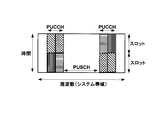
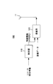
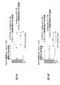
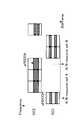
- FIG. 1 shows a subframe configuration of a downlink.
- a PDCCH that transmits a control signal and a PDSCH (Physical Downlink Shared Channel) that transmits a data signal are time-multiplexed.
- a terminal decodes control information transmitted to itself by PDCCH, and obtains information related to frequency allocation and adaptive control necessary for data reception on the downlink. Thereafter, the terminal decodes its own data included in the PDSCH based on the control information.
- the terminal uses the uplink PUSCH (Physical-Uplink-Shared-Channel) to transmit data based on the control information. Send.
- HARQ Hybrid automatic request
- the terminal determines whether or not the data has been correctly decoded based on a CRC (Cyclic redundancy checksum) added to the data. If the data is correctly decoded, the terminal feeds back ACK to the base station. On the other hand, if the data cannot be decoded correctly, the terminal feeds back a NACK to the base station and prompts retransmission of data in which an error is detected. Feedback of such ACK / NACK (acknowledgment response, hereinafter referred to as “A / N”) is transmitted on the uplink.
- CRC Cyclic redundancy checksum
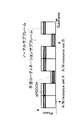
- a / N is transmitted on PUCCH (Physical-Uplink-Control-Channel: physical uplink control channel) if no data is allocated to PUSCH at the time of transmission.
- PUCCH Physical-Uplink-Control-Channel: physical uplink control channel
- the A / N is transmitted on either the PUCCH or the PUSCH.
- the base station instructs the terminal in advance as to whether to transmit using PUCCH or PUSCH.
- FIG. 2 shows an uplink subframe configuration including PUSCH and PUCCH.
- PUCCH formats 2a / 2b When transmitting A / N via PUCCH, there are multiple cases. For example, when the A / N transmission overlaps with CSI (Channel state information) feedback periodically transmitted on the uplink, PUCCH formats 2a / 2b is used. Also, in the downlink, when carrier aggregation (Carrier Aggregation) for bundling and transmitting a plurality of carriers is ON and the number of carriers is 3 or more, PUCCH format 3 is used. On the other hand, PUCCH formats 1a / 1b are used if the number of carriers is 2 or less even when carrier aggregation is OFF or ON and there is no control information to be transmitted other than A / N and uplink scheduling requests.
- CSI Channel state information
- a / N may be transmitted in PUCCH formats 1a / 1b. Most often. In the following, the description will focus on PUCCH formats 1a / 1b.
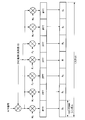
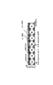
- FIG. 3 shows a slot configuration of PUCCH formats 1a / 1b.
- a / N signals transmitted from a plurality of terminals are spread by a Walsh sequence having a sequence length of 4 and a DFT (Discrete Fourier transform) sequence having a sequence length of 3, and are code-multiplexed and received by a base station.
- (W 0 , W 1 , W 2 , W 3 ) and (F 0 , F 1 , F 2 ) represent the aforementioned Walsh sequence and DFT sequence, respectively.
- a signal representing ACK or NACK is firstly spread on a frequency axis to a frequency component corresponding to one SC-FDMA symbol by a ZAC (Zero auto-correlation) sequence (sequence length 12 [subcarrier]). That is, an A / N signal component represented by a complex number is multiplied by a ZAC sequence having a sequence length of 12.
- an A / N signal after first spreading and a ZAC sequence as a reference signal are Walsh sequences (sequence length 4: W 0 to W 3, sometimes referred to as Walsh Code Sequence) and DFT sequences.
- Second spread is performed by (sequence length 3: F 0 to F 2 ).
- an orthogonal code sequence for example, Walsh sequence
- IFFT Inverse Fast Fourier Transform
- a / N signals from different terminals are spread using ZAC sequences corresponding to different cyclic shift amounts (Cyclic Shift Index) or orthogonal code sequences corresponding to different sequence numbers (Orthogonal Cover Index: OC index). ing.
- the orthogonal code sequence is a set of a Walsh sequence and a DFT sequence.
- the orthogonal code sequence may be referred to as a block-wise spreading code sequence. Therefore, the base station can separate a plurality of A / N signals that have been code-multiplexed and cyclic shift-multiplexed by using conventional despreading and correlation processing.
- a / N resource a code-RB resource in which A / N is transmitted is referred to as an A / N resource.
- the number of the A / N resource is determined by the RB number that transmits A / N, the code number in the RB, and the cyclic shift amount. Since multiplexing by cyclic shift of a ZAC sequence can also be regarded as a kind of code multiplexing, hereinafter, an orthogonal code and a cyclic shift may be collectively referred to as a code.
- a ZAC sequence to be used is determined based on the cell ID in order to reduce interference from other cells in the PUCCH. Since the correlation between different ZAC sequences is small, interference can be reduced by using different ZAC sequences between different cells.
- sequence hopping based on cell IDs and cyclic shift hopping have also been introduced. In these hoppings, cyclic shift hopping patterns determined based on cell IDs are used to cyclically shift in units of SC-FDMA symbols while maintaining mutual correlation on the cyclic shift axis and the orthogonal code axis.
- the combination of A / N signals that receive strong interference from other cells can be randomized while maintaining the orthogonal relationship between the A / N signals in the cell, and only some terminals can receive strong interference from other cells. You can prevent them from continuing to take it.
- a ZAC sequence is used for primary spreading and a block-wise spreading code sequence is used for secondary spreading.
- sequences that can be separated from each other by different cyclic shift amounts other than ZAC sequences may be used for first spreading.
- GCL Generalized Chirp like
- CAZAC Constant Amplitude Zero Auto Correlation
- ZC Zero Auto Correlation
- PN sequence such as M sequence and orthogonal gold code sequence
- self generated randomly by computer A sequence having a steep correlation characteristic may be used for the first spreading.
- any sequence may be used as a block-wise spreading code sequence as long as the sequences are orthogonal to each other or sequences that can be regarded as being substantially orthogonal to each other.
- a Walsh sequence or a Fourier sequence can be used for secondary spreading as a block-wise spreading code sequence.
- LTE employs allocation based on the PDCCH control information mapping result as a method of allocating different A / N resources to different terminals. That is, using the fact that the PDCCH control information is not mapped to the same resource among a plurality of terminals, PDCCH resources and PUCCH formats 1a / 1b A / N resources (hereinafter simply referred to as A / N resources) and Are in a one-to-one correspondence. This will be described in detail below.
- the PDCCH is composed of one or a plurality of L1 / L2 CCHs (L1 / L2 Control Channels).
- Each L1 / L2CCH is composed of one or a plurality of CCEs (Control Channel Elements). That is, CCE is a basic unit when mapping control information to PDCCH.
- CCE is a basic unit when mapping control information to PDCCH.
- one L1 / L2CCH is composed of a plurality (2, 4, 8) of CCEs, a plurality of consecutive CCEs starting from CCEs having even indexes are allocated to the L1 / L2CCH. It is done.
- the base station allocates L1 / L2 CCH to the resource allocation target terminal according to the number of CCEs required for reporting control information to the resource allocation target terminal.
- the base station maps and transmits the control information to the physical resource corresponding to the L1 / L2CCH CCE.
- each CCE is associated with an A / N resource on a one-to-one basis. Therefore, the terminal that has received the L1 / L2CCH specifies an A / N resource corresponding to the CCE that constitutes the L1 / L2CCH, and transmits an A / N signal to the base station using this resource (ie, code and frequency). To do.
- the terminal can perform A / N resources corresponding to the CCE having the smallest index among the plurality of PUCCH configuration resources respectively corresponding to the plurality of CCEs (that is, The A / N signal is transmitted to the base station using an A / N resource associated with a CCE having an even-numbered CCE index.
- the A / N resource number n PUCCH is determined based on the following formula (1) (see, for example, Non-Patent Document 3).
- the A / N resource number n PUCCH is the aforementioned A / N resource number.
- N represents an A / N resource offset value commonly given in the cell
- n CCE represents a CCE number to which the PDCCH is mapped. From formula (1), it can be seen that a certain range of A / N resources can be used according to the range that n CCE can take.
- a / N in which resources are determined depending on PDCCH control information scheduling in this manner is referred to as DA / N (Dynamic A / N: Dynamic ACK / NACK).
- a / N resources include frequency resources in addition to code resources. Since PUCCH and PUSCH share the same frequency band in the uplink, the PUCCH area including DA / N and the bandwidth of PUSCH are a trade-off.
- 3GPP TS 36.211 V10.4.0 “Physical Channels and Modulation (Release 10),” Dec. 2011
- 3GPP TS 36.212 V10.4.0 “Multiplexing and channel coding” (Release 10), “Dec. 2011
- 3GPP TS 36.213 V10.4.0 “Physical layer procedures (Release 10),” Dec. 2011
- PDCCH since the control information allocation area is limited, the number of terminals that can be allocated simultaneously and the amount of control information are limited. Also, it is assumed that PDCCH is received according to cell-specific parameters. In order to follow cell-specific parameters, PDCCH is suitable for CoMP (Coordinated multipoint operation) that coordinates between multiple cells or HetNet (Heterogeneous network) that operates by placing a pico base station in a cell of a macro base station. There is no problem. Therefore, Rel. 11, the adoption of E-PDCCH (enhanced PDCCH: extended physical downlink control channel) as a new control channel different from PDCCH is under consideration.
- CoMP Coordinatd multipoint operation
- HetNet Heterogeneous network
- E-PDCCH can increase the control information allocation area.
- E-PDCCH since E-PDCCH has the advantage that flexible control information allocation that is not restricted by the setting in units of cells can be performed, the introduction of E-PDCCH, in particular, CoMP that performs coordination between cells or interference between cells It is expected that operation suitable for HetNet where control is important will be possible.
- the uplink A / N ratio between the terminal controlled by the E-PDCCH control information and the terminal controlled by the PDCCH control information A collision may occur.
- an A / N resource is unnecessarily secured so that an A / N collision does not occur, and the PUSCH band is reduced.
- An object of the present invention is to provide a wireless communication terminal that avoids an A / N collision and avoids a wasteful reduction in PUSCH bandwidth while avoiding A / N collision in a system in which E-PDCCH control information is transmitted It is to provide a base station apparatus and a resource allocation method.
- a radio communication terminal transmits an extended physical downlink control channel (a control signal including an ACK / NACK indicator from one or a plurality of Configuration candidates using any one Configuration ( E-PDCCH), and a resource used for an ACK / NACK signal of downlink data based on the configuration information of the E-PDCCH used for transmission / reception of the E-PDCCH and the ACK / NACK indicator
- the controller includes a control unit that selects from designated resources that are designated in advance, and a transmission unit that transmits the ACK / NACK signal using the selected designated resource.
- the radio communication base station is the configuration used for transmission of the E-PDCCH among one or a plurality of E-PDCCH configurations previously notified to the radio communication terminal.
- a control unit for determining a resource for transmitting an ACK / NACK signal of downlink data from a wireless communication terminal from among designated resources specified in advance according to an ACK / NACK indicator included in the control signal,
- a transmission unit that transmits a control signal including an ACK / NACK index representing a determination result via an E-PDCCH using Configuration corresponding to the determined specified resource.
- a resource allocation method receives a control signal including an ACK / NACK indicator via an extended physical downlink control channel (E-PDCCH), and uses the ACK / NACK indicator and E-PDCCH configuration. Based on a plurality of ACK / NACK resources separated from each other in the frequency and code domain, one of the designated resource candidates designated in advance is selected.
- E-PDCCH extended physical downlink control channel
- the use efficiency of A / N resources is improved while avoiding collision of A / N signals with downlink data.
- FIG. 3 is a block diagram showing the main part of the base station according to the first embodiment.
- FIG. 3 is a block diagram showing details of the base station according to the first embodiment.
- FIG. 3 is a block diagram showing a main part of the terminal according to the first embodiment.
- FIG. 3 is a block diagram showing details of the terminal according to the first embodiment.
- the figure which shows an example of the scheduling of E-PDCCH in Embodiment 1 The figure explaining the A / N resource of the E-PDCCH terminal switched based on ARI according to Embodiment 1
- FIG. 1 shows an example of the scheduling of E-PDCCH in Embodiment 1
- the figure explaining the A / N resource of the E-PDCCH terminal switched based on ARI according to Embodiment 1 The figure which shows the setting range of the A / N resource candidate according to Configuration of E-PDCCH
- FIG. 1 The figure which shows an example of the scheduling of E-PDCCH in Embodiment 2
- FIG. The figure which shows an example of the scheduling of E-PDCCH in Embodiment 3 The figure which shows the A / N resource specified based on the search space where E-PDCCH which concerns on Embodiment 3 is transmitted
- FIG. 15 is a diagram illustrating an example of E-PDCCH scheduling in the fourth embodiment
- FIG. 18 shows an example of E-PDCCH scheduling in the seventh embodiment.
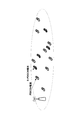
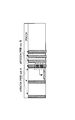
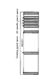
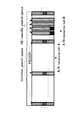
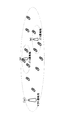
- FIG. 4 shows an example of a downlink subframe when E-PDCCH is transmitted.
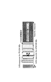
- FIG. 5 shows a system configuration when E-PDCCH is employed.
- E-PDCCH has some or all of the following characteristics. (1) Unlike the PDCCH transmitted using resources common to all terminals, the transmission is performed using frequency resource blocks allocated to each terminal. (2) Unlike PDCCH demodulated using a reference signal common to all terminals in the cell, demodulation is performed using a terminal-specific reference signal given to each terminal. (3) Unlike the PDCCH that is scrambled using a scramble code common to all terminals in the cell, the scramble is performed using a scramble code given to each terminal. (4) Whether or not to transmit the E-PDCCH can be changed by setting.
- the E-PDCCH has a frequency resource block (PRB) set for each terminal and is transmitted by the PRB.
- PRB numbers 2, 4,..., 24, 26 are set as E-PDCCH.
- the E-PDCCH is configured with one or a plurality of resource eCCEs (enhanced control channel elements).
- eCCEs enhanced control channel elements
- a PDCCH terminal refers to a terminal that receives PDCCH control information and performs communication control
- an E-PDCCH terminal refers to a terminal that receives E-PDCCH control information and performs communication control.
- E-PDCCH the control information area is increased, and flexible control information allocation that is not constrained by setting in units of cells becomes possible.
- a plurality of E-PDCCHs with different settings can be used in a cell, or E-PDCCHs with the same setting can be used between cells. Therefore, the introduction of E-PDCCH is expected to be particularly effective in operation suitable for CoMP that performs cooperation between cells and HetNet in which interference control between cells is important.
- the simplest method is to determine an A / N resource number in the E-PDCCH, for example, as in the following equation (2), similarly to the PDCCH.
- n PUCCH E-PDCCH is a resource number to which the E-PDCCH terminal transmits A / N.
- N e is the A / N resource offset value
- n eCCE is the number of the eCCE to which the E-PDCCH is mapped.
- N e is a DA / N resource offset parameter, which may be a cell-specific value or a value given independently for each terminal.
- This method has the advantage that there is no need to notify A / N resources for each terminal, and there is no possibility of A / N collision between E-PDCCH terminals.
- FIG. 6 shows an example in which four A / N resources for PDCCH terminals and four A / N resources for E-PDCCH terminals are set. It is assumed that the A / N resource for the PDCCH terminal is determined according to the conventional equation (1). Further, it is assumed that the A / N resource for the E-PDCCH terminal is determined according to Equation (2).
- the A / N resources are widely distributed by determining the A / N resources of the E-PDCCH terminal based on the eCCE number.
- the degree of dispersion varies depending on the range of values that the eCCE number can take and Equation (2). For example, when eCCE numbering as shown in FIG. 4A is performed, the distribution of A / N resources becomes very large, and the band that should have been able to transmit PUSCH is reduced. This causes degradation of uplink throughput.
- FIG. 6 illustrates a situation where A / N collides between a PDCCH terminal and an E-PDCCH terminal.
- a plurality of E-PDCCHs may be set in a cell, and in this case, A / N collision may occur between different E-PDCCHs. Since the collision greatly degrades the A / N quality and cannot be tolerated, if an A / N resource collision occurs between a plurality of terminals, it is necessary to give up the allocation.
- Another method is a method of allocating A / N resources for each terminal in advance by using RRC (Radio resource control) control information or the like.
- RRC Radio resource control
- FIG. 7 is a table in which A / N resource candidates set by the RRC control information are associated with ARI values. The terminal determines the A / N resource from the value indicated by the ARI of the decoded PDCCH.
- a / N resource setting independent of E-PDCCH scheduling becomes possible.
- the same A / N resource candidate may be set for a plurality of E-PDCCH terminals, and the A / N resource may be controlled by the ARI of the E-PDCCH transmitted to each terminal.
- the allocation block can be avoided by adjusting the ARI, it is not necessary to readjust the scheduling of the PDCCH and the E-PDCCH.
- a / N resource selection by ARI can set A / N resource candidates only in a number corresponding to the number of bits of ARI. For example, when the ARI is 2 bits, there are 4 selectable A / N resources. Considering that a collision between an A / N resource and a terminal on which a PDCCH terminal or other E-PDCCH is set may occur, some of the four A / N resources may not be used. For this reason, there are few choices only with ARI, and there is a problem that flexible A / N resource control cannot be performed.
- the number of A / N resource candidates can be increased by increasing the number of ARI bits.
- an excessive increase in the number of ARI bits increases the overhead of E-PDCCH, which is undesirable from the viewpoint of performance and coverage.
- the communication system according to the first embodiment (1) increases the number of A / N resource candidates without increasing the number of ARI bits.
- the purpose is to achieve the two points of increasing simultaneously.
- the communication system includes one base station 100 and a plurality of terminals 200 in the cell.
- FIG. 8 is a block diagram illustrating a main part of the base station 100.
- the base station 100 converts a control unit 110 that generates a plurality of control information to be transmitted to each of a plurality of terminals 200, and converts the control information and transmission data into a signal for wireless transmission, via an antenna 11. And a transmitter 120 for wirelessly transmitting signals.
- the control unit 110 generates control information for each terminal 200 from downlink resource allocation information and the like. In addition, control section 110 schedules control information to be transmitted to each terminal 200 on PDCCH or E-PDCCH. At this time, the E-PDCCH is transmitted by any one of one or a plurality of configurations set in advance for the terminal 200. Also, the E-PDCCH terminal is notified of which of the notification A / N resource candidates designated in advance by the RRC notification is used to transmit the A / N using the ARI included in the E-PDCCH. . Therefore, the control unit 110 generates control information for the E-PDCCH terminal including the ARI, and outputs the control information to the transmission unit 120.
- the transmission unit 120 wirelessly transmits a signal of each channel including transmission data and control information. That is, transmitting section 120 transmits transmission data on PDSCH, transmits control information on PDCCH terminals on PDCCH, and transmits control information on E-PDCCH terminals on E-PDCCH.
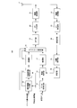
- FIG. 9 is a block diagram showing details of the base station 100.
- the base station 100 includes an antenna 11, a control information generation unit 12, a control information encoding unit 13, modulation units 14 and 17, a data encoding unit 15, a retransmission control unit 16, A frame configuration unit 18, an IFFT unit 19, a CP addition unit 20, a wireless transmission unit 21 and the like are provided.
- the base station 100 includes a radio reception unit 22, a CP removal unit 23, a despreading unit 24, a correlation processing unit 25, a determination unit 26, and the like.
- control information generation unit 12 mainly functions as the control unit 110, and the configuration in which the control information encoding unit 13 is applied to the wireless transmission unit 21 and the data encoding unit 15 to the wireless transmission unit 21 is mainly the transmission unit 120. Function as.
- the base station 100 transmits PDCCH, E-PDCCH, and PDSCH on the downlink.
- Base station 100 also receives PUCCH carrying an A / N signal on the uplink.
- transmission of downlink PDCCH, E-PDCCH, and PDSCH, which are closely related to the features of the present embodiment, and uplink of PUCCH for the downlink data Main components related to reception on the line are mainly shown. Then, illustration and description of components related to reception of uplink data are omitted.
- the downlink control signal and data signal generated by the base station 100 are separately encoded and modulated, and input to the subframe configuration unit 18.
- the control information generation unit 12 generates control information for each terminal 200 from the resource allocation result (resource allocation information) and coding rate information of each terminal 200 that performs downlink allocation.
- the control information for each terminal 200 includes terminal ID information indicating which terminal 200 the control information is addressed to. For example, a CRC bit masked with the ID number of the terminal 200 to which the control information is notified is included in the control information as terminal ID information.
- different information is included in the control information mapped to the PDCCH and the control information mapped to the E-PDCCH.
- the control information mapped to the E-PDCCH includes an ARI that indicates which A / N resource candidate notified in advance by RRC is to be used.
- the generated control information for each terminal 200 is input to the control information encoding unit 13.
- the control information encoding unit 13 encodes the control information for each terminal 200 independently based on the encoding rate information. Encoding may be the same or different between control information mapped to PDCCH and control information mapped to E-PDCCH.
- the output of the control information encoding unit 13 is input to the modulation unit 14.
- the modulation unit 14 modulates the control information for each terminal 200 independently.
- the modulation may be the same or different between control information mapped to PDCCH and control information mapped to E-PDCCH.
- the output of the modulation unit 14 is input to the subframe configuration unit 18.
- the data encoding unit 15 adds CRC bits masked based on the ID of each terminal 200 to the data bit sequence transmitted to each terminal 200, and performs error correction encoding.
- the output of the data encoding unit 15 is input to the retransmission control unit 16.
- the retransmission control unit 16 holds the encoded transmission data for each terminal 200 and outputs the transmission data to the modulation unit 17 at the first transmission. On the other hand, the retransmission control unit 16 outputs transmission data corresponding to the retransmission to the modulation unit 17 for the terminal 200 to which the NACK signal is input from the determination unit 26, that is, the terminal 200 that performs the retransmission.
- the modulation unit 17 performs data modulation on the input data encoding sequence for each terminal 200.
- the modulation sequence is input to the subframe configuration unit 18.
- the subframe configuration unit 18 maps the input control information sequence and data sequence to resources divided by the time and frequency of the subframe based on the resource allocation information. As a result, the subframe configuration unit 18 configures a subframe and outputs the subframe to the IFFT unit 19.
- the IFFT unit 19 performs IFFT (Inverse Fourier Transform) on the input transmission subframe to obtain a time waveform.
- the obtained time waveform is input to the CP adding unit 20.
- CP adding section 20 adds a CP to each OFDM symbol in the subframe and outputs the result to radio transmitting section 21.
- the radio transmission unit 21 performs radio modulation on the input symbol to the carrier frequency band and transmits a modulated downlink signal via the antenna 11.
- the radio receiving unit 22 receives an input from the antenna 11 that has received the A / N signal of the terminal 200 and performs radio demodulation.
- the demodulated downlink signal is input to the CP removing unit 23.
- the CP removing unit 23 removes the CP from each SC-FDMA (Single Carrier-Frequency-Division Multiple Access) symbol in the downlink signal.
- the symbol after CP removal is input to the despreading unit 24.
- the despreading unit 24 performs despreading with a corresponding orthogonal code in order to extract the A / N of the target terminal 200 from the A / N signals of the plurality of terminals 200 that are code-multiplexed.
- the despread signal is output to the correlation processing unit 25.
- the correlation processing unit 25 performs a correlation process using a ZAC sequence in order to extract A / N.
- the signal after the correlation processing is input to the determination unit 26.
- the determination unit 26 determines whether the A / N of the terminal 200 is ACK or NACK. When the determination result is ACK, the determination unit 26 prompts the retransmission control unit 16 to transmit the next data. On the other hand, when the determination result is NACK, the determination unit 26 prompts the retransmission control unit 16 to perform retransmission.
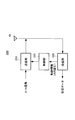
- FIG. 10 is a block diagram illustrating a main part of the terminal.
- the terminal 200 includes a receiving unit 230 that receives control information and downlink data via the antenna 41, a control unit 220 that determines a resource for transmitting an A / N signal based on the control information, and an A / N using the determined resource. And a transmission unit 210 that transmits a signal.
- the terminal 200 becomes an E-PDCCH terminal when it is set to receive E-PDCCH control information, and becomes a PDCCH terminal when it is set to receive PDCCH control information.
- the terminal 200 may be set to receive both. That is, the terminal 200 configured to receive both attempts to receive control information from both the E-PDCCH and the PDCCH, and if the control information can be extracted from the E-PDCCH, the terminal 200 transmits the control information to the E-PDCCH terminal. If control information can be extracted, it becomes a PDCCH terminal. When there is no particular notification or designation, terminal 200 is a PDCCH terminal.
- the terminal 200 is notified of E-PDCCH configuration that may include its own control information from an upper layer such as RRC.
- the configuration may be one or plural.
- the terminal 200 checks which of the respective configurations has transmitted its own E-PDCCH.
- Base station 100 transmits E-PDCCH to terminal 200 using any one configuration.
- the receiving unit 230 receives received data via the PDSCH, and receives control information via the E-PDCCH or PDCCH. That is, receiving section 230 receives control information including an ARI via E-PDCCH in the case of E-PDCCH terminal 200, and receives control information via PDCCH in the case of PDCCH terminal 200. .
- the receiving unit 230 outputs the received control information to the control unit 220.
- control unit 220 When the control unit 220 is the E-PDCCH terminal 200, the transmission resource of the A / N signal of the received data is notified by the RCC or the like based on the received E-PDCCH configuration and the ARI value. Which A / N resource (RRC notification A / N resource) is used is identified. Further, in the case of PDCCH terminal 200, control unit 220 determines an A / N signal transmission resource in the same manner as the previous PDCCH terminal. Control unit 220 outputs the determination content to transmission unit 210.
- the transmission unit 210 wirelessly transmits an A / N signal of received data using the determined resource.
- FIG. 11 is a block diagram showing details of the terminal.
- the terminal 200 includes an antenna 41, a radio reception unit 42, a CP removal unit 43, an FFT unit 44, an extraction unit 45, a data demodulation unit 46, a data decoding unit 47, a determination unit 48, as shown in FIG.
- the terminal 200 also includes an IFFT unit 60 for reference signals, a CP adding unit 61, and a spreading unit 62.
- control processing unit 52 mainly functions as the control unit 220.
- the configuration applied from the A / N signal modulation unit 53 to the wireless transmission unit 59 mainly functions as the transmission unit 210, and the configuration applied from the wireless reception unit 42 to the determination unit 48 and from the wireless reception unit 42 to the control information determination unit 51. It mainly functions as the receiving unit 230.
- Terminal 200 receives control information mapped to PDCCH or E-PDCCH in downlink and downlink data mapped to PDSCH.
- Terminal 200 transmits PUCCH on the uplink.
- reception of downlink specifically, PDCCH, E-PDCCH, PDSCH
- downlink reception that are closely related to the features of the present embodiment. Only components related to data transmission on uplink (specifically, PUCCH) are shown.
- the radio reception unit 42 receives an input from the antenna 41 that has received the downlink signal transmitted from the base station, performs radio demodulation, and outputs it to the CP removal unit 43.
- the CP removal unit 43 removes the CP from each OFDM symbol time waveform in the subframe and outputs it to the FFT unit 44.
- the FFT unit 44 performs FFT (Fast Fourier Transform) to perform OFDM (Orthogonal frequency division multiplexing) demodulation on the input time waveform to obtain subframes in the frequency domain.
- FFT Fast Fourier Transform
- OFDM Orthogonal frequency division multiplexing
- the extraction unit 45 extracts control information for the terminal from the PDCCH region or the E-PDCCH region. It is assumed that information indicating whether the control information is included in PDCCH or E-PDCCH is instructed in advance by base station 100 (not shown).
- the extraction unit 45 extracts one or a plurality of control information candidates from the control information region to which the control information of the control information may be mapped using the coding rate information of the control information, and the control information demodulation unit 49 Output to. Further, when the result is obtained from the control information determination unit 51, the extraction unit 45 extracts a data signal for the terminal from the received subframe based on the resource allocation result included in the control information addressed to the terminal. The obtained data signal is input to the data demodulator 46.
- the control information demodulator 49 demodulates one or more input control information and outputs it to the control information decoder 50.
- the control information decoding unit 50 performs decoding on one or more input demodulated sequences using the coding rate information of the control information.
- the decoding result is input to the control information determination unit 51.
- the control information determination unit 51 determines the control information addressed to the own terminal from the one or more decoding results using the terminal ID information. For the determination, a CRC bit masked by the own terminal ID information included in the control information is used. When there is control information addressed to the terminal itself, the control information determination unit 51 outputs the control information to the extraction unit 45. Further, the control information determination unit 51 outputs the control information to the control processing unit 52.
- the control processing unit 52 performs different operations depending on the case of the PDCCH terminal 200 and the case of the E-PDCCH terminal 200.
- the control processing unit 52 obtains the resource number of the A / N signal based on the equation (1) from the resource (CCE) number to which the control information is mapped.
- the control processing unit 52 determines each spreading code used for the primary spreading, the secondary spreading, and the reference signal and the frequency resource block (RB) for transmitting the PUCCH from the obtained A / N signal resource number.
- These pieces of information are input to the primary spreading unit 54, the secondary spreading unit 57, and the reference signal spreading unit 62.
- the control processing unit 52 determines the A / P notified as the RRC control information based on the received E-PDCCH configuration and the two values indicated by the ARI included in the control information. Decide which of the N resource candidates to use.
- the RRC notification A / N resource is instructed from base station 100 to terminal 200 in advance (not shown).
- the control processing unit 52 determines each spreading code used for the primary spreading, the secondary spreading and the reference signal corresponding to the instructed A / N resource number, and a frequency resource block (RB) for transmitting the PUCCH. Then, the control processing unit 52 outputs each spreading code to the primary spreading unit 54, the secondary spreading unit 57, and the reference signal spreading unit 62, respectively.
- RB frequency resource block
- the data demodulator 46 demodulates the input data signal for the terminal itself.
- the demodulation result is input to the data decoding unit 47.
- the data decoder 47 decodes the input demodulated data.
- the decoding result is input to the determination unit 48.
- the determination unit 48 determines whether the decoding result is correct using the CRC masked with the ID of the terminal 200. If the decoding result is correct, the determination unit 48 outputs an ACK signal to the A / N signal modulation unit 53 and extracts received data. If the decoding result is not correct, the determination unit 48 outputs a NACK signal to the A / N signal modulation unit 53.
- the A / N signal modulation unit 53 generates modulation symbols having different values depending on whether the input signal is ACK or NACK.
- the generated modulation symbol is input to primary spreading section 54.
- the primary spreading unit 54 performs primary spreading of the A / N signal using the ZAC sequence input from the control processing unit 52, and outputs the A / N signal after the primary spreading to the IFFT unit 55.
- the primary spreading unit 54 performs primary spreading of the A / N signal using a different cyclic shift amount for each SC-FDMA symbol.
- the IFFT unit 55 performs IFFT for each SC-FDMA symbol input from the primary spreading unit 54 and outputs the obtained time waveform to the CP adding unit 56.
- CP adding unit 56 adds a CP for each input SC-FDMA time waveform, and outputs this signal to secondary spreading unit 57.
- the secondary spreading unit 57 performs secondary spreading on the SC-FDMA time waveform after the CP addition using a block-wise spreading code sequence.
- the spreading code the code instructed by the control processing unit 52 is used.
- the second spread sequence is input to multiplexing section 58.
- the multiplexing unit 58 time-multiplexes two sequences respectively input from the reference signal spreading unit 62 and the secondary spreading unit 57 to form a PUCCH subframe.
- the time-multiplexed signal is input to the wireless transmission unit 59.
- the radio transmission unit 59 performs radio modulation on the input signal to the carrier frequency band, and transmits the uplink signal from the antenna 41 by radio.
- the IFFT unit 60 performs IFFT on the reference signal and outputs the obtained time waveform to the CP adding unit 61.
- CP adding section 61 adds a CP to the time waveform of the input reference signal, and outputs this signal to spreading section 62.
- the diffusion unit 62 performs diffusion on the time waveform after CP addition.
- the spreading code the code instructed by the control processing unit 52 is used.
- the spread sequence is input to multiplexing unit 58.
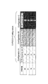
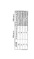
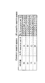
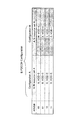
- FIG. 12 is a table showing the ARI included in the E-PDCCH and the A / N resource determined by the configuration of the E-PDCCH.
- the base station 100 notifies A / N resource candidates determined by the ARI value and E-PDCCH configuration before the PDSCH transmission / reception.
- the A / N resource candidates are A to D, W to Z, and O to R in FIG. An RRC control signal or the like is used for these notifications.
- Step (2) The base station 100 determines a terminal 200 to which data is allocated in each subframe and performs scheduling in the PDSCH. In addition to the amount of traffic to each terminal 200, CSI feedback or a sounding reference signal (SRS) transmitted by the terminal 200 is also used for scheduling.
- SRS sounding reference signal
- Step (3) The base station 100 generates control information including a scheduling result for each terminal 200 and schedules them to the PDCCH or E-PDCCH.
- the base station 100 determines the configuration for transmitting the E-PDCCH for the terminal 200 in which a plurality of E-PDCCH configurations are set, and performs scheduling based on the configuration.
- the base station 100 confirms whether an A / N resource collision occurs between all the terminals 200 that have scheduled control information.
- the base station 100 can avoid the A / N resource collision by changing the PDCCH scheduling result, the E-PDCCH ARI value, the E-PDCCH configuration, and the like. Find out.
- the base station 100 gives up scheduling for the terminal 200 in which the collision occurs (allocation block).
- Step (4) When the control information scheduling for all terminals 200 is completed, the base station 100 wirelessly transmits PDCCH and E-PDCCH control information and PDSCH downlink data on the downlink.
- Step (5) The terminal 200 obtains control information addressed to itself from the received signal, and extracts and decodes the data signal.
- the terminal 200 that may transmit control information on the E-PDCCH also confirms which Configuration is being used for transmission among one or a plurality of configurations that can be used.
- terminal 200 identifies a code and frequency resource for transmitting an A / N signal corresponding to the received data signal based on the control information.
- the E-PDCCH terminal 200 determines which A / N resource candidate notified in advance by RRC is to be used based on the configuration of the E-PDCCH addressed to itself and the ARI value included in the E-PDCCH. .
- Step (6) Terminal 200 specifies ACK or NACK according to the determination result of the data signal, and transmits an A / N signal using the A / N resource (code and frequency resource) specified as described above. To do.
- the A / N resource can be increased without increasing the number of ARI bits for the terminal 200 in which a plurality of E-PDCCH configurations are set.
- the number of candidates can be increased.
- the number of A / N resource candidates is gradually increased as necessary. Can be increased.
- a / N resource candidates that is, A to D, W to Z, and O to R in FIG. 12, are all A / N resources notified in advance by RRC control information or the like. Therefore, the base station 100 easily adjusts the A / N resource as compared with the allocation method as shown in Equation (2), in which the A / N resource is determined by the resource on which the E-PDCCH is scheduled, such as an eCCE number. it can. This also reduces the circuit scale of the base station 100.
- the number of ARI bits may be changed by E-PDCCH configuration.
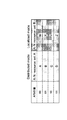
- FIG. 13A and FIG. 13B show examples in which the number of bits of the ARI differs depending on the configuration.
- FIG. 13A shows an example in which Configuration A has a 2-bit ARI only, and other Configurations have a 1-bit configuration.
- FIG. 13B only Configuration A is 1 bit, and the other configuration is an example of 2 bits.
- an overhead reduction effect by reducing the number of bits of the ARI can also be obtained.
- Configuration A is frequently used for E-PDCCH and Configuration B and C are used only for a few E-PDCCH terminals
- the overhead for ARI bits can be reduced, since there are few E-PDCCH terminals for Configuration B and C, the deterioration of the allocation block rate due to the reduction in the number of ARI bits can be suppressed.
- the number of ARI bits for Configuration A and the number of ARI bits for Configuration B and C are reduced. May be more.
- the number of ARI bits of Configuration A is reduced to reduce the number of information bits included in the control information, thereby allowing transmission / reception in various environments.
- the reception quality of PDCCH Configuration A can be improved.
- the range of A / N resource candidates that can be specified by the ARI may be limited for each E-PDCCH configuration.
- FIG. 14 shows an example in which a range in which A / N resource candidates can be set is limited by E-PDCCH configuration.
- the A / N resource range of Configuration B and C is limited only to a region different from the A / N resource range of the PDCCH terminal.
- the A / N resource range of Configuration A is It is limited to the same area as the A / N resource range of the PDCCH terminal.
- the configuration A / N resource candidate setting range for Configuration A may be narrowed, and the A / N resource candidate setting range for Configuration B or C may be wide.
- Configuration A having a narrow setting range is used as long as no allocation block occurs, resources that can be allocated to the PUSCH can be secured and the uplink throughput can be improved.
- Embodiment 2 [Outline of communication system]
- E-PDCCH is set as a PRB set composed of one or a plurality of PRBs for a terminal.
- the E-PDCCH is transmitted / received in the set PRB set.
- one or more E-PDCCH PRB sets are set for each E-PDCCH terminal.
- Information on the set PRB set is notified from the base station to the terminal by RRC control information or the like.
- the number of PRB sets to be set can be changed for each terminal.
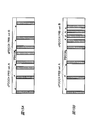
- FIG. 15 shows an example in which two PRB sets are set in a subframe.
- FIG. 15A shows an example in which the PRB frequency interval is the same in two PRB sets
- FIG. 15B shows an example in which the PRB frequency interval is different in the two PRB sets.
- PRB frequency interval can also be set for one or a plurality of PRB sets. Note that a plurality of predetermined PRB sets are defined, and a PRB set to be used may be selected from among them.
- Base station configuration The configuration of base station 100 is the same as that of Embodiment 1 except that the processing content of control unit 110 is mainly different. The processing content of the control unit 110 will be described in detail in the following description of the operation.
- Terminal configuration The configuration of terminal 200 is the same as that of Embodiment 1 except that the processing content of control unit 220 is mainly different. The processing content of the control unit 220 will be described in detail in the following description of the operation.
- FIG. 16 is a table showing A / N resources determined by the ARI included in the E-PDCCH and the PRB set of the E-PDCCH.
- the setting need not be notified.
- the PRB set setting and the number of PRB sets to be notified are determined for each individual terminal 200. For example, in FIG. 15, PRB set A and B are set for a certain terminal 200, and only PRB set A is set for a certain terminal 200.
- the base station 100 notifies A / N resource candidates determined by the ARI value and the ERBDC PRB set before the PDSCH transmission / reception.
- the A / N resource candidates are A to D and W to Z in FIG. For these notifications, an RRC control signal or the like is used.
- Step (2) The base station 100 determines a terminal 200 to which data is allocated in each subframe and performs scheduling in the PDSCH. In addition to the amount of traffic to each terminal 200, CSI feedback or a sounding reference signal (SRS) transmitted by the terminal 200 is also used for scheduling.
- SRS sounding reference signal
- Step (3) The base station 100 generates control information including a scheduling result for each terminal 200 and schedules them to the PDCCH or E-PDCCH.
- the base station 100 determines a PRB set for transmitting the E-PDCCH to the terminal 200 in which a plurality of E-PDCCH PRB sets are set, and performs scheduling in the PRB set.
- the base station 100 confirms whether or not A / N resource collision occurs between all scheduled terminals 200.
- the base station 100 avoids the A / N resource collision by changing the PDCCH scheduling result, the E-PDCCH ARI value, the E-PDCCH PRB set, and the like. Find out if you can.
- the base station 100 gives up scheduling for the terminal 200 in which the collision occurs (allocation block).
- Step (4) When the control information mapping for all terminals 200 is completed, the base station 100 wirelessly transmits PDCCH and E-PDCCH control information and PDSCH downlink data on the downlink.
- Step (5) The terminal 200 obtains control information addressed to itself from the received signal, and extracts and decodes the data signal.
- the terminal 200 that may transmit control information on the E-PDCCH also confirms which PRB set is being transmitted from among one or more PRB sets that can be set and used in advance.
- terminal 200 identifies a code and frequency resource for transmitting an A / N signal corresponding to the received data signal based on the control information.
- the E-PDCCH terminal 200 determines which of the A / N resource candidates notified in advance by RRC based on the PRB set to which the E-PDCCH addressed to the terminal is transmitted and the ARI value included in the E-PDCCH. Whether to use is determined (for example, see FIG. 17).
- Step (6) Terminal 200 specifies ACK or NACK according to the determination result of the data signal, and transmits an A / N signal using the A / N resource (code and frequency resource) specified as described above. To do.
- a / N can be achieved without increasing the number of ARI bits for terminal 200 in which a plurality of E-PDCCH PRB sets are set.
- the number of resource candidates can be increased.
- the number of A / N resource candidates that can be selected by the terminal 200 in which a plurality of PRB sets are set increases, so that the terminal 200 in which only a single PRB set is set.
- the probability that the A / N resource becomes an allocation block can also be reduced.
- the A / N resource is used when the number is larger than the number of terminals 200 allocated.
- a / N resources for example, A to D
- the number of PRB sets to be used can be reduced.
- the number of downlink PRBs for transmitting data can be increased, so that the throughput per terminal can be increased.
- the number of A / N resource candidates is increased stepwise as necessary. Can be increased.
- a / N resource candidates that is, A to D and W to Z in FIG. 16, are all A / N resources notified in advance by RRC control information or the like. Therefore, the base station 100 easily adjusts the A / N resource as compared with the allocation method as shown in Equation (2), in which the A / N resource is determined by the resource on which the E-PDCCH is scheduled, such as an eCCE number. it can. This also reduces the circuit scale of the base station 100.
- the number of ARI bits may be changed by the PRB set of E-PDCCH.
- the number of bits of the ARI included in the E-PDCCH transmitted by the PRB set A is 2 bits
- the number of bits of the ARI included in the E-PDCCH transmitted by the PRB set B is 1 bit, and the like.
- the ARI may be 0 bits depending on the PRB set.
- one A / N resource notified as RRC control information is used.
- an overhead reduction effect by reducing the number of bits of the ARI can be obtained.
- PRB set A is frequently used for E-PDCCH and PRB set B is used only for a few E-PDCCH terminals
- the ARI bit number of PRB set A can be increased, and the ARI bit number of PRB set B can be reduced.
- the overhead for ARI bits can be reduced, but since the number of PRB set B E-PDCCH terminals is small, the deterioration of the allocation block rate due to the reduction of the number of ARI bits can be suppressed to a small level.
- the ARI bit number of PRB set B is reduced and the ARI bit number of PRB set B is reduced. May be more.
- the reception quality of E-PDCCH PRB set A is reduced by reducing the number of ARI bits of PRB set A and reducing the number of information bits included in the control information while achieving the same effect as in the first embodiment. Can be improved.
- the range of A / N resource candidates that can be specified by ARI may be limited for each PRB set of E-PDCCH.
- PRB set A is a PRB set that is frequently used for E-PDCCH
- PRB set B is a PRB set that is used only for a few E-PDCCH terminals
- PRB set B is E-PDCCH.
- the A / N resource candidate settable range of PRB set A may be narrowed, and the A / N resource candidate settable range of PRB set B or C may be widened.
- the PRB set A having a narrow setting range is used unless an allocation block occurs, resources that can be allocated to the PUSCH can be ensured and the uplink throughput can be improved.
- the terminal 200 can always determine one A / N resource specified by the ARI regardless of the setting of the PRB set, it is possible to prevent the use efficiency deterioration of the PUCCH resource.
- the A / N resource corresponding to the PRB set having the smaller PRB frequency interval included in the PRB set is allocated. It may be used. Since the frequency diversity effect of the frequency interval of the PRB set increases as the spread increases, E-PDCCH terminals with various communication environments and communication qualities can be received. Therefore, it is conceivable to use a PRB set mainly having a wide frequency interval. In such a case, there is a high possibility that a larger number of terminals 200 are accommodated in a PRB set having a larger frequency interval.
- a / N resources corresponding to the PRB set with the smaller PRB frequency interval included in the PRB set are used.
- / N resource collision probability can be lowered.
- the A / N resource corresponding to the PRB set with the larger PRB frequency interval included in the PRB set can be used, so that more terminals 200 can be accommodated.
- an A / N resource corresponding to the PRB set having a larger PRB frequency interval is included in the PRB set. It may be used.
- the downlink PDSCH it is more continuous for the downlink PDSCH to use a PRB set with a small frequency interval. Since the bandwidth can be increased, a high downlink throughput per terminal can be achieved. Therefore, in this case, an operation mainly using a PRB set having a small frequency interval spread is conceivable.
- Embodiment 3 [Outline of communication system]
- E-PDCCH is transmitted / received to / from a terminal using a search space (SS) configured by one or more PRBs.
- the terminal receives the E-PDCCH in the set search space.
- SS search space
- one or more search spaces are set for each E-PDCCH terminal.
- a search space common to many terminals 200 is called a common search space (CSS), and a search space common to only one or a few terminals 200 is a UE-specific search space (USS: UE-specific Search Space).
- CCS common search space
- USS UE-specific Search Space
- FIG. 19 shows an example in which CSS and USS are set in a subframe.
- the CSS also accommodates a terminal 200 having a low average received signal-to-interference noise power ratio (SINR) of E-PDCCH or a terminal 200 that cannot perform E-PDCCH frequency scheduling with high accuracy.
- SINR received signal-to-interference noise power ratio
- the USS accommodates terminals 200 that do not need to be accommodated by the CSS or terminals that can achieve the frequency scheduling effect, so that there is a possibility that the PRB interval is narrowed and concentrated in a specific frequency band. high.
- the PRB for setting the search space may be set for each terminal 200 or may be a predetermined setting.
- Base station configuration The configuration of base station 100 is the same as that of Embodiment 1 except that the processing content of control unit 110 is mainly different. The processing content of the control unit 110 will be described in detail in the following description of the operation.
- Terminal configuration The configuration of terminal 200 is the same as that of Embodiment 1 except that the processing content of control unit 220 is mainly different. The processing content of the control unit 220 will be described in detail in the following description of the operation.
- FIG. 20 is a table showing A / N resources determined by the ARI included in the E-PDCCH and the search space of the E-PDCCH when both CSS and USS are set.
- CSS configuration information that can be used for all E-PDCCH terminals may be defined in advance.
- the search space setting and the number of search spaces are determined for each individual terminal 200. For example, in FIG. 19, CSS and USS are set for a certain terminal 200, and only CSS is set for a certain terminal 200.
- the base station 100 notifies A / N resource candidates determined by the ARI value and the search space before the PDSCH transmission / reception.
- the A / N resource candidates are A to D and W to Z in FIG. For these notifications, an RRC control signal or the like is used.
- Step (2) The base station 100 determines a terminal 200 to which data is allocated in each subframe and performs scheduling in the PDSCH. In addition to the amount of traffic to each terminal 200, CSI feedback or a sounding reference signal (SRS) transmitted by the terminal 200 is also used for scheduling.
- SRS sounding reference signal
- Step (3) The base station 100 generates control information including a scheduling result for each terminal 200 and schedules them to the PDCCH or E-PDCCH.
- Base station 100 determines a search space for transmitting E-PDCCH for terminal 200 in which a plurality of search spaces are set, and performs scheduling in the search space.
- the base station 100 confirms whether or not A / N resource collision occurs between all scheduled terminals 200.
- the base station 100 avoids the A / N resource collision by changing the PDCCH scheduling result, the E-PDCCH ARI value, the E-PDCCH search space, and the like. Find out if you can.
- the base station 100 gives up scheduling for the terminal 200 in which the collision occurs (allocation block).
- Step (4) When the control information mapping for all terminals 200 is completed, the base station 100 wirelessly transmits PDCCH and E-PDCCH control information and PDSCH downlink data on the downlink.
- Step (5) The terminal 200 obtains control information addressed to itself from the received signal, and extracts and decodes the data signal.
- the terminal 200 that may transmit control information on the E-PDCCH also confirms in which search space one or more search spaces that may be set in advance and used may be transmitted.
- terminal 200 identifies a code and frequency resource for transmitting an A / N signal corresponding to the received data signal based on the control information.
- the E-PDCCH terminal 200 determines which of the A / N resource candidates notified in advance by RRC based on the search space in which the E-PDCCH addressed to itself is transmitted and the ARI value included in the E-PDCCH. Whether to use is determined (for example, see FIG. 21).
- Step (6) Terminal 200 specifies ACK or NACK according to the determination result of the data signal, and transmits an A / N signal using the A / N resource (code and frequency resource) specified as described above. To do.
- a / N can be provided to terminal 200 in which a plurality of E-PDCCH search spaces are set without increasing the number of ARI bits.
- the number of resource candidates can be increased.
- the number of A / N resource candidates that can be selected by terminal 200 in which a plurality of search spaces are set increases, so that terminal 200 in which only a single search space is set up can be selected.
- the probability that an A / N resource becomes an allocation block can be reduced.
- the A / N resource is used when the number is larger than the number of terminals 200 allocated.
- a / N resources for example, A to D
- the number of search spaces to be used can be reduced.
- the number of downlink PRBs for transmitting data can be increased, so that the throughput per terminal can be increased.
- Embodiment 3 by additionally setting a search space that can be used for an E-PDCCH terminal according to the communication environment or terminal status, the number of A / N resource candidates can be set as needed. Can be increased.
- a / N resource candidates that is, A to D and W to Z in FIG. 20, are all A / N resources notified in advance by RRC control information or the like. Therefore, the base station 100 easily adjusts the A / N resource as compared with the allocation method as shown in Equation (2), in which the A / N resource is determined by the resource on which the E-PDCCH is scheduled, such as an eCCE number. it can. This also reduces the circuit scale of the base station 100.
- the number of ARI bits may be changed according to the E-PDCCH search space.
- the number of ARI bits included in the E-PDCCH transmitted by CSS is 2 bits
- the number of ARI bits included in the E-PDCCH transmitted by USS is 1 bit
- the ARI may be 0 bits depending on the search space.
- one A / N resource is always used as the RRC control information.
- the CSS coverage is expanded, and terminals with various average reception SINRs can receive the E-PDCCH.
- increasing the number of ARI bits included in the CSS increases the degree of freedom in A / N resource selection of the terminal 200 that transmits and receives E-PDCCH in CSS, and assigns it.
- the block rate can be reduced.
- the range of A / N resource candidates that can be specified by ARI may be limited.
- the RRC control signal overhead can be reduced by limiting the A / N resource candidate setting range.
- a / N resource candidate setting range For example, in an operation in which CSS is a search space frequently used for E-PDCCH and USS is a search space used only for E-PDCCH terminals with few, terminal 200 that transmits E-PDCCH in USS is Few. Therefore, by taking a wider A / N resource candidate setting range for CSS and narrowing a USS A / N resource candidate setting range, it is possible to reduce the RRC overhead while obtaining the same effect as in the third embodiment. .
- the CSS A / N resource candidate setting range may be narrowed and the USS A / N resource candidate setting range may be wide.
- a CSS having a narrow setting range is used as long as no allocation block occurs, resources that can be allocated to the PUSCH can be secured and the uplink throughput can be improved.
- terminal 200 that transmits E-PDCCH in USS is used. Many.
- the third embodiment it is possible to solve the above-mentioned problem that it is impossible to discriminate by specifying that when the E-PDCCH is transmitted / received by the PRB included in any search space, it is assumed that the E-PDCCH is always transmitted from the CSS.
- terminal 200 can always determine one A / N resource to be designated by ARI regardless of the setting of the search space, so that it is possible to prevent the use efficiency of the PUCCH resource from deteriorating.
- the A / N resource corresponding to the USS when the E-PDCCH is transmitted / received by the PRB included in any search space, the A / N resource corresponding to the USS may be used. Since CSS is an E-PDCCH received over a wide range, the corresponding A / N resources may also be used now. Therefore, when an E-PDCCH is transmitted / received by a PRB included in any search space, an A / N resource corresponding to the USS is used, so that an A / N resource that is likely to be free is allocated. Therefore, the A / N resource collision probability can be lowered. In addition, by doing this, CSS A / N resources can be used, so that more terminals 200 can be accommodated.
- Embodiment 4 [Outline of communication system]
- the E-PDCCH is transmitted / received to / from the terminal in the Distributed mode or the Localized mode.
- the Distributed mode is a mode in which the E-PDCCH is arranged and transmitted across two or more PRBs
- the Localized mode is a mode in which the E-PDCCH is arranged and transmitted in one PRB.
- Each E-PDCCH terminal is set to either or both of the distributed mode and the localized mode.
- the distributed mode since a single control information is arranged in a plurality of PRBs, a high frequency diversity effect can be obtained.
- the localized mode since control information is arranged only in a single PRB, the frequency diversity effect is small, but the frequency scheduling effect and the interference avoidance effect are obtained.
- Information indicating which transmission mode can be used is notified from the base station 100 to the terminal 200 by RRC control information or the like.
- FIG. 22 shows an example in which the E-PDCCH transmitted in the Distributed mode and the Localized mode is present in the subframe.
- a spread PRB is used, so that a frequency diversity effect can be obtained.
- the localized mode since control information is transmitted with a single PRB, a frequency diversity effect cannot be obtained, but a frequency scheduling effect and an interference avoidance effect can be obtained.
- Base station configuration The configuration of base station 100 is the same as that of Embodiment 1 except that the processing content of control unit 110 is mainly different. The processing content of the control unit 110 will be described in detail in the following description of the operation.
- Terminal configuration The configuration of terminal 200 is the same as that of Embodiment 1 except that the processing content of control unit 220 is mainly different. The processing content of the control unit 220 will be described in detail in the following description of the operation.
- FIG. 23 is a table showing the ARI included in the E-PDCCH and the A / N resource determined by the search space of the E-PDCCH when the distributed mode and the localized mode are set.
- Step (1) The base station 100 notifies the terminal 200 that is likely to transmit control information on the E-PDCCH prior to transmission / reception of the PDSCH, of the use of the E-PDCCH. Note that the terminal 200 that does not transmit on the E-PDCCH need not be notified. The terminal 200 also receives the control information on the assumption that the control information is transmitted on the PDCCH when there is no notification or recognition. Also, the terminal 200 that is likely to transmit control information on the E-PDCCH is notified of setting information on a transmission mode that may be used before transmission / reception of the PDSCH.
- both a distributed mode and a localized mode are set for a certain terminal 200, and only one of the terminals 200, for example, the distributed mode is set for a certain terminal 200.
- base station 100 before transmitting / receiving PDSCH, base station 100 notifies A / N resource candidates determined by the ARI value and the transmission mode for transmitting / receiving E-PDCCH.
- the A / N resource candidates are A to D and W to Z in FIG. For these notifications, an RRC control signal or the like is used.
- Step (2) The base station 100 determines a terminal 200 to which data is allocated in each subframe and performs scheduling in the PDSCH. In addition to the amount of traffic to each terminal 200, CSI feedback or a sounding reference signal (SRS) transmitted by the terminal 200 is also used for scheduling.
- SRS sounding reference signal
- Step (3) The base station 100 generates control information including a scheduling result for each terminal 200 and schedules the PDCCH and the E-PDCCH. For terminal 200 in which a plurality of search spaces are set by E-PDCCH, a transmission mode used for transmission is also determined.
- the base station 100 confirms whether or not A / N resource collision occurs between all scheduled terminals 200.
- the base station 100 avoids the A / N resource collision by changing the PDCCH scheduling result, the E-PDCCH ARI value, the E-PDCCH transmission mode, and the like. Find out if you can.
- the base station 100 gives up scheduling for the terminal 200 in which the collision occurs (allocation block).
- Step (4) When the control information scheduling for all terminals 200 is completed, the base station 100 wirelessly transmits PDCCH and E-PDCCH control information and PDSCH downlink data on the downlink.
- Step (5) The terminal 200 obtains control information addressed to itself from the received signal, and extracts and decodes the data signal.
- the terminal 200 that may transmit control information on the E-PDCCH also confirms in which transmission mode one or a plurality of transmission modes that can be set and used in advance is transmitted.
- terminal 200 identifies a code and frequency resource for transmitting an A / N signal corresponding to the received data signal based on the control information.
- the E-PDCCH terminal 200 determines which of the A / N resource candidates notified in advance by RRC based on the transmission mode in which the E-PDCCH addressed to itself is transmitted and the ARI value included in the E-PDCCH. Whether to use is determined (for example, see FIG. 24).
- Step (6) Terminal 200 specifies ACK or NACK according to the determination result of the data signal, and transmits an A / N signal using the A / N resource (code and frequency resource) specified as described above. To do.
- the A / N resource is used when the number is larger than the number of terminals 200 allocated.
- a / N resources to, for example, A to D
- the transmission mode to be used can be limited.
- the E-PDCCH of any terminal 200 can obtain the frequency diversity effect, so that high-quality reception of E-PDCCH can be realized.
- the transmission mode to the localized mode the E-PDCCH of any terminal 200 is transmitted by a single PRB, so the total number of PRBs used for the E-PDCCH can be reduced. Thereby, the number of PRBs that can be used for PDSCH can be increased, and the downlink throughput per terminal can be improved.
- the number of A / N resource candidates can be set as needed by additionally setting a transmission mode that can be used for the E-PDCCH terminal according to the communication environment or the terminal status. Can be increased.
- a / N resource candidates that is, A to D and W to Z in FIG. 23 are all A / N resources notified in advance by RRC control information or the like. Therefore, the base station 100 easily adjusts the A / N resource as compared with the allocation method as shown in Equation (2), in which the A / N resource is determined by the resource on which the E-PDCCH is scheduled, such as an eCCE number. it can. This also reduces the circuit scale of the base station 100.
- the control signal transmitted on the E-PDCCH uses only one unit resource such as eCCE, that is, when the aggregation level is 1, it is regarded that the signal is transmitted in the localized mode and A / N resources may be determined.
- the distributed mode which has a high frequency diversity effect and can be received by many terminals 200, is more likely to contain a larger number of terminals. Therefore, when the aggregation level is 1, the A / N resource allocation block probability can be reduced by determining that the A / N is determined as being transmitted in the localized mode.
- the number of ARI bits may be changed depending on the E-PDCCH transmission mode.
- the number of bits of the ARI included in the E-PDCCH transmitted in the distributed mode is 2 bits
- the number of bits of the ARI included in the E-PDCCH transmitted in the localized mode is 1 bit
- the ARI may be 0 bits depending on the transmission mode.
- the ARI is 0 bit, one A / N resource given as RRC control information is always used.
- an overhead reduction effect can be obtained by reducing the number of bits of the ARI.
- the number of ARI bits included in the E-PDCCH in the distributed mode is increased than in the localized mode, thereby suppressing the influence of the reduction in the number of ARI bits.
- the allocated block rate can be reduced.
- the effect of reducing the number of ARI bits can be suppressed by increasing the number of ARI bits included in the localized mode E-PDCCH than in the distributed mode. Meanwhile, the allocation block rate can be reduced.
- the range of A / N resource candidates that can be specified by the ARI may be limited for each transmission mode in which the E-PDCCH is transmitted and received.
- an effect of reducing the overhead of the RRC control signal by limiting the A / N resource candidate setting range can be obtained.
- the A / N resource candidate settable range in the Distributed mode is widened, and the A / N resource candidate settable range in the Localized mode is narrowed to obtain the same effect as in the fourth embodiment, while reducing the RRC overhead. Can be reduced.
- the E-PDCCH is transmitted / received by any one of one or a plurality of component carriers (CC) set in the terminal.
- CC component carriers
- the base station 100 Prior to the PDSCH transmission, the base station 100 notifies the terminal 200 of the A / N resource determined by the ARI value and the CC to which the E-PDCCH is transmitted.
- the base station 100 determines the A / N resource used by the E-PDCCH terminal 200 based on the ARI value included in the E-PDCCH and the CC to which the E-PDCCH is transmitted. Then, similarly to Embodiments 1 to 4, terminal 200 uses A / R to be used based on the ARI value included in received E-PDCCH and from which CC E-PDCCH is detected. N resources are selected from A / N resource candidates notified in advance. For example, as shown in FIG.
- terminal 200 determines that the ARI value and E-PDCCH are CC1,
- the A / N resource to be used is determined depending on which of the CCs 2 is transmitted.
- the number of A / N resource candidates is increased without increasing the number of ARI bits for terminal 200 in which a plurality of CCs are set. Can be increased. Furthermore, according to the fifth embodiment, the number of A / N resource candidates that can be selected by the terminal 200 in which a plurality of CCs are set increases, so that the A / N of the terminal 200 in which only a single CC is set. The probability that N resources are allocated blocks can be reduced.
- all A / N resources that can be selected by the ARI and the CC are resources notified in advance by RRC control information or the like. Therefore, the base station 100 easily adjusts the A / N resource as compared with the allocation method as shown in Equation (2), in which the A / N resource is determined by the resource on which the E-PDCCH is scheduled, such as an eCCE number. it can. This also reduces the circuit scale of the base station 100.
- Embodiment 6 E-PDCCH is transmitted in either an interference coordination subframe or a normal subframe.
- FIG. 26 shows an example of transmitting and receiving both interference coordination subframes and normal subframes.
- the interference coordination subframe some or all of the base stations 100 perform transmission with low power.
- Base station 100 notifies in advance the time relationship between interference coordination subframes and normal subframes to some or all terminals 200 using RRC control information or the like.
- the A / N resource used by E-PDCCH terminal 200 is the value of the ARI included in E-PDCCH and the E-PDCCH is transmitted in an interference coordination subframe or a normal subframe. It is decided by.
- base station 100 Prior to PDSCH transmission, base station 100 notifies terminal 200 of A / N resources determined by the ARI value and the type of subframe in which E-PDCCH is transmitted.
- terminal 200 uses A / N to be used depending on the ARI value included in the received E-PDCCH and in which subframe the E-PDCCH is received.
- a resource is selected from A / N resource candidates notified in advance.
- the A / N resource can be increased without increasing the number of ARI bits for the terminal 200 to which the information of the interference coordination subframe is notified.
- the number of candidates can be increased.
- the number of A / N resource candidates that can be selected by terminal 200 in which the interference coordination subframe is set increases, so that the A / N of terminal 200 in which only the normal subframe is set is selected. The probability that N resources are allocated blocks can be reduced.
- all A / N resources that can be selected based on the ARI and the type of subframe are resources that are notified in advance by RRC control information or the like. Therefore, the base station 100 easily adjusts the A / N resource as compared with the allocation method as shown in Equation (2), in which the A / N resource is determined by the resource on which the E-PDCCH is scheduled, such as an eCCE number. it can. This also reduces the circuit scale of the base station 100.
- the sixth embodiment the case where the interference coordination is performed in units of subframes has been described. However, even when the interference coordination is performed in units of PRB, the same effect can be achieved by using the sixth embodiment. Can do.
- terminal 200 determines an A / N resource based on whether the E-PDCCH is an interference coordination PRB or normal PRB and the value of ARI.
- whether or not to perform interference coordination is set in units of PRBs, so that A / N resources used by PRBs can be changed even in the same subframe.
- Embodiments 2 to 6 described so far are not used alone, but may be used in combination. By combining them, it is possible to further increase the degree of freedom in selecting A / N resources without increasing the number of ARI bits.
- the communication system according to the seventh embodiment includes one or a plurality of nodes (macro base station, pico base station) and a plurality of terminals.
- a plurality of pico nodes are arranged in a cell of a macro base station that forms a large cell (hereinafter, the macro base station in CoMP scenario 4 is referred to as a macro node and the pico base station is referred to as a pico node).
- the base station can perform downlink coordinated transmission and uplink coordinated reception using a plurality of nodes.
- the pico base station may be something like RRH (Remote radio head). It is assumed that the macro base station and the pico base station are connected by a low-delay large-capacity interface such as an optical fiber to form a CoMP set. In the following, in order to avoid a complicated description, the same reference numerals are given to the same components as those in the first embodiment, and only differences from the first embodiment will be described.
- RRH Remote radio head
- base station (macro base station, pico base station) 100 is mainly the same as that of Embodiment 1 except that the processing content of control unit 110 is mainly different.
- a plurality of base stations 100 are arranged in the macro cell, and as described above, they are connected by a low-delay and large-capacity interface to form a CoMP set.
- the processing content of the control unit 110 will be described in detail in the following description of the operation.
- Terminal configuration The configuration of terminal 200 is the same as that of Embodiment 1 except that the processing content of control unit 220 is mainly different. The processing content of the control unit 220 will be described in detail in the following description of the operation.
- the base station 100 notifies the A / N resource candidate determined by the ARI value and the E-PDCCH configuration as RRC control information before the PDSCH transmission / reception.
- the A / N resource candidates are A to D and W to Z in FIG.
- the base station 100 notifies the virtual cell ID corresponding to each A / N resource as RRC control information.
- the virtual cell ID is an ID necessary for determining a base sequence number, a sequence hopping pattern, or a cyclic shift (CS) hopping pattern necessary for transmitting the PUCCH. Rel.
- this ID is a cell ID, which is a parameter common to all the terminals 200 in the cell.
- the virtual cell ID can be set for each terminal 200 individually. Suppose that it is a parameter.
- Step (2) The base station 100 determines a terminal 200 to which data is allocated in each subframe and performs scheduling in the PDSCH. In addition to the amount of traffic to each terminal 200, CSI feedback or a sounding reference signal (SRS) transmitted by the terminal 200 is also used for scheduling.
- SRS sounding reference signal
- Step (3) The base station 100 generates control information including a scheduling result for each terminal 200 and schedules the PDCCH and the E-PDCCH. For the terminal 200 in which a plurality of E-PDCCH configurations are set, the configuration used for E-PDCCH transmission is also determined.
- the base station 100 confirms whether or not A / N resource collision occurs between all scheduled terminals 200.
- the base station 100 can avoid the A / N resource collision by changing the PDCCH scheduling result, the E-PDCCH ARI value, the E-PDCCH configuration, and the like. Find out.
- the base station 100 gives up scheduling for the terminal 200 in which the collision occurs (allocation block).
- Step (4) When the control information mapping for all terminals 200 is completed, the base station 100 wirelessly transmits PDCCH and E-PDCCH control information and PDSCH downlink data on the downlink.
- Step (5) The terminal 200 obtains control information addressed to itself from the received signal, and extracts and decodes the data signal.
- the terminal 200 that may transmit control information on the E-PDCCH also confirms which Configuration is being used for transmission among one or a plurality of configurations that can be used.
- terminal 200 identifies a code and frequency resource for transmitting an A / N signal corresponding to the received data signal based on the control information.
- the E-PDCCH terminal 200 determines which A / N resource candidate notified in advance by RRC is to be used based on the configuration of the E-PDCCH addressed to itself and the ARI value included in the E-PDCCH. .
- terminal 200 also determines a virtual cell ID corresponding to the A / N resource.
- FIG. 30 shows an example of an A / N resource determined by E-PDCCH configuration and ARI and a virtual cell ID corresponding to the A / N resource.
- VCID-0 and VCID-1 are set as virtual cell IDs, but different virtual cell IDs may be set for all A / N resources.
- Step (6) Terminal 200 specifies ACK or NACK according to the determination result of the data signal, and transmits an A / N signal using the A / N resource (code and frequency resource) specified as described above. To do. Transmission of the A / N signal is performed by PUCCH. Also, terminal 200 generates a PUCCH base sequence number, a base sequence hopping pattern, and a CS hopping pattern using a virtual cell ID corresponding to the A / N resource.
- PUCCH in addition to the effects of Embodiment 1, PUCCH can be generated with different virtual cell IDs according to the configuration of E-PDCCH.
- a / N resources of PUCCH can be orthogonalized only between terminals 200 having the same virtual cell ID or cell ID. Therefore, according to Embodiment 7, it is possible to transmit an A / N signal that can be multiplexed with a different group of terminals 200 for each E-PDCCH configuration.
- a terminal 200 located between a macro base station and a pico base station can receive an A / N signal that can be multiplexed with a macro terminal received by the macro base station, and a pico terminal received by the pico base station.
- a / N signals that can be multiplexed can be generated according to the configuration of the E-PDCCH.
- the A / N signal can be switched to the virtual cell ID received by the E-PDCCH transmission station. Since the A / N signal is a signal used for retransmission control, it can be retransmitted by receiving it at the E-PDCCH transmission base station while suppressing delay or backhaul burden.
- the virtual cell ID but also parameters such as transmission power or timing offset may be set to be dynamically switched by E-PDCCH configuration. Thereby, even when the distance from the terminal 200 to the macro base station and the distance from the terminal 200 to the pico base station are greatly different, it is possible to switch and receive the A / N signal receiving station.
- Embodiment 7 there are two virtual cell IDs, but one may be a cell-specific ID (cell ID). This is because one of the E-PDCCH transmission base stations is likely to be a cell connected to a terminal on the downlink. Thus, by making one cell a known cell ID, it is possible to reduce the overhead of the RRC control signal while obtaining the same effect as in the seventh embodiment.
- cell ID cell-specific ID
- each functional block used in the description of the above embodiment is typically realized as an LSI which is an integrated circuit. These may be individually made into one chip, or may be made into one chip so as to include a part or all of them.
- the name used here is LSI, but it may also be called IC, system LSI, super LSI, or ultra LSI depending on the degree of integration.
- the method of circuit integration is not limited to LSI, and may be realized by a dedicated circuit or a general-purpose processor.
- An FPGA Field Programmable Gate Array
- a reconfigurable processor that can reconfigure the connection and setting of circuit cells inside the LSI may be used.
- the radio communication terminal transmits the control signal including the ACK / NACK indicator from one or a plurality of configuration candidates using any one configuration.
- the number of A / N resource candidates without increasing the number of ARI bits for the terminal 200 in which a plurality of E-PDCCH configurations are set in advance. Accordingly, the allocation block probability can be reduced even in the terminal 200 in which only a single E-PDCCH configuration is set. Further, by adding Configuration that can be used for the E-PDCCH terminal according to the communication environment or terminal status, the number of A / N resource candidates can be increased stepwise as necessary.
- the ACK / NACK indicator has a different number of states depending on the configuration of the E-PDCCH to be transmitted, and the control unit is used for transmission / reception of E-PDCCH. Based on the received configuration information and the ACK / NACK indicator, a resource to be used for an ACK / NACK signal for downlink data is selected from designated resources designated in advance.
- the range of the designated resource that can be designated differs depending on the configuration used for transmission / reception of E-PDCCH, and the control unit uses the configuration used for transmission / reception of E-PDCCH.
- the control unit uses the configuration used for transmission / reception of E-PDCCH.
- a resource used for the ACK / NACK signal of the downlink data is selected from designated resources designated in advance.
- the range that the ACK / NACK resource can take can be narrowed, and the overhead required for notification of the specified resource can be reduced.
- the configuration candidate is a frequency resource block (PRB) set.
- PRB frequency resource block
- the number of designated resources can be increased without increasing the number of states of the ACK / NACK index for the terminal 200 in which a plurality of E-PDCCH PRB sets are set in advance. Further, by adding a PRB set that can be used for the E-PDCCH terminal according to the communication environment or the terminal status, the number of A / N resource candidates can be increased stepwise as necessary. Furthermore, since the increased designated resources are all ACK / NACK resources notified from the base station in advance, it is easy for the base station to adjust ACK / NACK resources between terminals, and the base station can be operated with a small circuit scale or algorithm. .
- the control unit is configured in advance when a PRB to which a control signal including the ACK / NACK indicator is transmitted / received is a PRB belonging to two or more PRB sets. It is assumed that it belongs to the determined specific PRB set, and the ACK / NACK resource is selected from the specified resources specified in advance by the specific PRB set and the ACK / NACK index.
- the ACK / NACK resource can be uniquely determined, so that the base station can recognize ACK / N corresponding to a plurality of PRB sets. There is no need to make NACK resources available, and the utilization efficiency of ACK / NACK resources is improved.
- the control unit is most effective when a PRB to which a control signal including the ACK / NACK indicator is transmitted / received is a PRB belonging to two or more PRB sets. It is considered that the interval between the PRB having the lowest frequency and the PRB having the highest frequency belongs to a specific PRB set, and the ACK / NACK resource is designated in advance by the specific resource specified by the specific PRB set and the ACK / NACK index. Choose from.
- the ACK / NACK resource is determined on the assumption that it belongs to a PRB set with a small number of terminals, so that the possibility that the ACK / NACK is used by other terminals is low, and the probability of becoming an allocation block is reduced. Can be reduced.
- the configuration candidate is a search space.
- the number of designated resources without increasing the number of states of the ACK / NACK index for the terminal 200 in which a plurality of search spaces are set in advance. Further, by adding a search space that can be used for the E-PDCCH terminal according to the communication environment or the terminal status, the number of A / N resource candidates can be increased stepwise as necessary. Furthermore, since the increased designated resources are all ACK / NACK resources notified from the base station in advance, it is easy for the base station to adjust ACK / NACK resources between terminals, and the base station can be operated with a small circuit scale or algorithm. .
- the control unit is configured such that when a PRB to which a control signal including the ACK / NACK indicator is transmitted / received is a PRB belonging to two or more search spaces, It is assumed that it belongs to a unique search space (USS), and an ACK / NACK resource is selected from designated resources designated in advance by the USS and the ACK / NACK indicator.
- USS unique search space
- an ACK / NACK resource can be uniquely determined. Therefore, an ACK / NACK resource corresponding to a plurality of search spaces by a base station This eliminates the need to leave the ACK / NACK resource, and improves the utilization efficiency of the ACK / NACK resource. Moreover, the probability of becoming an allocation block can be reduced by using the ACK / NACK resource corresponding to USS which is highly likely to have a small number of simultaneously accommodated terminals.
- the Configuration candidate is a transmission mode used for transmission of E-PDCCH, and the transmission mode is a distributed mode or 1 that is transmitted using two or more PRBs. This is a localized mode in which only one PRB is transmitted.
- the number of designated resources without increasing the number of states of the ACK / NACK indicator for the terminal 200 in which both the Distributed mode and the Localized mode are set in advance. Also, by adding a transmission mode that can be used for the E-PDCCH terminal according to the communication environment or the terminal status, the number of A / N resource candidates can be increased stepwise as necessary. Furthermore, since the increased designated resources are all ACK / NACK resources notified from the base station in advance, it is easy for the base station to adjust ACK / NACK resources between terminals, and the base station can be operated with a small circuit scale or algorithm. .
- the configuration candidate is a component carrier (CC).
- the number of designated resources without increasing the number of states of the ACK / NACK indicator for the terminal 200 in which the use of a plurality of CCs is set in advance. Also, by adding CCs that can be used for E-PDCCH terminals according to the communication environment or terminal status, the number of A / N resource candidates can be increased stepwise as necessary. Furthermore, since the increased designated resources are all ACK / NACK resources notified from the base station in advance, it is easy for the base station to adjust ACK / NACK resources between terminals, and the base station can be operated with a small circuit scale or algorithm. .
- the control unit performs ACK / NACK signal of downlink data based on the configuration information of the E-PDCCH used for transmission / reception of the E-PDCCH and the ACK / NACK indicator. And a virtual cell ID used for generating a PUCCH base sequence, a hopping pattern, or a cyclic shift (CS) hopping pattern for transmitting an ACK / NACK signal, and a designated resource and a designated virtual cell designated in advance Each of the IDs is selected from the ID, and the transmission unit transmits the ACK / NACK signal using the selected designated resource and the designated virtual cell ID.
- CS cyclic shift
- the base station apparatus determines which configuration is used for transmitting the E-PDCCH among one or a plurality of E-PDCCH configurations that are previously notified to the radio communication terminal.
- a control unit for determining a resource for transmitting an ACK / NACK signal of downlink data from a wireless communication terminal from among designated resources specified in advance according to an ACK / NACK indicator included in the control signal,
- a transmission unit that transmits a control signal including an ACK / NACK index representing a determination result via an E-PDCCH using Configuration corresponding to the determined specified resource.
- the designated resource of the E-PDCCH terminal that can be designated by the ACK / NACK indicator can be switched by the configuration of the E-PDCCH to be transmitted. Therefore, the number of ACK / NACK options can be increased without increasing the number of states of the ACK / NACK indicator.
- the configuration is a frequency resource block (PRB) set.
- PRB frequency resource block
- the designated resource of the E-PDCCH terminal that can be designated by the ACK / NACK indicator can be switched by the PRB set of the E-PDCCH to be transmitted. Therefore, the number of ACK / NACK options can be increased without increasing the number of states of the ACK / NACK indicator.
- the configuration is a search space.
- the designated resource of the E-PDCCH terminal that can be designated by the ACK / NACK indicator can be switched by the search space of the E-PDCCH to be transmitted. Therefore, the number of ACK / NACK options can be increased without increasing the number of states of the ACK / NACK indicator.
- the configuration is a transmission mode used for transmission of E-PDCCH, and the transmission mode is a distributed mode or a single transmission mode transmitted by two or more PRBs. This is a localized mode transmitted only by PRB.
- the designated resource of the E-PDCCH terminal that can be designated by the ACK / NACK indicator can be switched according to the transmission mode of the E-PDCCH to be transmitted. Therefore, the number of ACK / NACK options can be increased without increasing the number of states of the ACK / NACK indicator.
- the configuration is a component carrier (CC).
- the designated resource of the E-PDCCH terminal that can be designated by the ACK / NACK indicator can be switched according to which CC the E-PDCCH is transmitted. Therefore, the number of ACK / NACK options can be increased without increasing the number of states of the ACK / NACK indicator.
- the control unit is configured to use the configuration used for transmission of the E-PDCCH among one or a plurality of E-PDCCH configurations previously notified to the radio communication terminal.
- the resource for transmitting the ACK / NACK signal of the downlink data from the wireless communication terminal and the virtual cell ID for generating the PUCCH are specified in advance by the ACK / NACK index included in the control signal.
- the transmission unit determines from among the specified resource and the specified virtual cell ID, and the transmission unit transmits a control signal including an ACK / NACK index representing a determination result of the control unit to the determined specified resource and the specified virtual cell ID. E-PD using the corresponding configuration Transmitted via the CH.
- the designation resource of the E-PDCCH terminal that can be designated by the ACK / NACK indicator can be switched according to which configuration is used to transmit the E-PDCCH. Therefore, the number of ACK / NACK options can be increased without increasing the number of states of the ACK / NACK indicator.
- the virtual cell ID for generating the PUCCH according to which Configuration is used to transmit the E-PDCCH, it is possible to switch the terminal group capable of multiplexing the ACK / NACK signal transmitted by the PUCCH.
- the resource allocation method receives a control signal including an ACK / NACK indicator via an extended physical downlink control channel (E-PDCCH), and configures the ACK / NACK indicator and the E-PDCCH. Based on the above, one of the plurality of ACK / NACK resources separated from each other in the frequency and code domain is selected from the designated resource candidates designated in advance.
- E-PDCCH extended physical downlink control channel
- the designated resource of the E-PDCCH terminal that can be designated by the ACK / NACK indicator can be switched by the configuration of the E-PDCCH to be transmitted. Therefore, the number of ACK / NACK options can be increased without increasing the number of states of the ACK / NACK indicator.
- the configuration is a frequency resource block (PRB) set.
- PRB frequency resource block
- the designated resource of the E-PDCCH terminal that can be designated by the ACK / NACK indicator can be switched by the PRB set in which the E-PDCCH is transmitted and received. Therefore, the number of ACK / NACK options can be increased without increasing the number of states of the ACK / NACK indicator.
- the configuration is a search space.
- the designated resource of the E-PDCCH terminal that can be designated by the ACK / NACK indicator can be switched by the search space of the E-PDCCH to be transmitted. Therefore, the number of ACK / NACK options can be increased without increasing the number of states of the ACK / NACK indicator.
- the configuration is a transmission mode used for transmission / reception of E-PDCCH, and the transmission mode is a distributed mode or a single PRB transmitted by two or more PRBs. This is a localized mode that is transmitted only in the above.
- the designated resource of the E-PDCCH terminal that can be designated by the ACK / NACK indicator can be switched according to the transmission mode of the E-PDCCH to be transmitted. Therefore, the number of ACK / NACK options can be increased without increasing the number of states of the ACK / NACK indicator.
- the configuration is a component carrier (CC).
- the designated resource of the E-PDCCH terminal that can be designated by the ACK / NACK indicator can be switched according to which CC the E-PDCCH is transmitted. Therefore, the number of ACK / NACK options can be increased without increasing the number of states of the ACK / NACK indicator.
- a PUCCH base sequence, hopping pattern, or cyclic shift for transmitting an ACK / NACK signal based on the ACK / NACK indicator and Configuration used for transmission / reception of E-PDCCH A virtual cell ID necessary for generating the hopping pattern is further selected.
- the designation resource of the E-PDCCH terminal that can be designated by the ACK / NACK indicator can be switched according to which configuration is used to transmit the E-PDCCH. Therefore, the number of ACK / NACK options can be increased without increasing the number of states of the ACK / NACK indicator.
- the virtual cell ID for generating the PUCCH according to which Configuration is used to transmit the E-PDCCH, it is possible to switch the terminal group capable of multiplexing the ACK / NACK signal transmitted by the PUCCH.
- the present invention can be applied to a radio communication terminal, a base station apparatus, a resource allocation method, and the like of a mobile communication system.
- Control information generation part Control information encoding part 14, 17 Modulation part 15 Data encoding part 16 Retransmission control part 18 Sub-frame structure part 19 IFFT part 20 CP addition part 21 Radio transmission part 22 Radio reception part 23 CP removal Unit 24 despreading unit 25 correlation processing unit 26 determination unit 41 antenna 42 wireless reception unit 43 CP removal unit 44 FFT unit 45 extraction unit 46 data demodulation unit 47 data decoding unit 48 determination unit 49 control information demodulation unit 50 control information decoding unit 51 Control information determination unit 52 Control processing unit 53 A / N signal modulation unit 54 Primary spreading unit 55, 60 IFFT unit 56 CP adding unit 57 Secondary spreading unit 58 Multiplexing unit 59 Wireless transmission unit 61 CP adding unit 62 Spreading unit 100 Base Station 110 Control unit 120 Transmission unit 200 Terminal 210 Transmission unit 220 Control unit 230 Reception unit
Abstract
Priority Applications (11)
| Application Number | Priority Date | Filing Date | Title |
|---|---|---|---|
| US14/342,283 US9591519B2 (en) | 2012-08-02 | 2013-06-21 | Wireless communication terminal, base station device, resource allocation method |
| JP2014509956A JP6308394B2 (ja) | 2012-08-02 | 2013-06-21 | 無線通信端末および無線通信方法 |
| CN201380002808.7A CN103959886B (zh) | 2012-08-02 | 2013-06-21 | 无线通信终端、基站装置以及资源分配方法 |
| EP13825710.0A EP2882250B1 (fr) | 2012-08-02 | 2013-06-21 | Terminal de communication sans fil et procédé d'attribution de ressource |
| EP23160309.3A EP4216646A1 (fr) | 2012-08-02 | 2013-06-21 | Terminal de communication sans fil, dispositif de station de base, procédé d'attribution de ressources |
| US15/401,817 US10014987B2 (en) | 2012-08-02 | 2017-01-09 | Wireless communication terminal, base station device, resource allocation method |
| US15/994,774 US10355831B2 (en) | 2012-08-02 | 2018-05-31 | Wireless communication terminal, base station device, resource allocation method |
| US16/377,713 US10581563B2 (en) | 2012-08-02 | 2019-04-08 | Wireless communication terminal, base station device, resource allocation method |
| US16/749,053 US10972231B2 (en) | 2012-08-02 | 2020-01-22 | Wireless communication terminal, base station device, resource allocation method |
| US17/195,233 US11569946B2 (en) | 2012-08-02 | 2021-03-08 | Integrated circuit |
| US18/066,964 US11881951B2 (en) | 2012-08-02 | 2022-12-15 | Integrated circuit |
Applications Claiming Priority (2)
| Application Number | Priority Date | Filing Date | Title |
|---|---|---|---|
| JP2012172224 | 2012-08-02 | ||
| JP2012-172224 | 2012-08-02 |
Related Child Applications (2)
| Application Number | Title | Priority Date | Filing Date |
|---|---|---|---|
| US14/342,283 A-371-Of-International US9591519B2 (en) | 2012-08-02 | 2013-06-21 | Wireless communication terminal, base station device, resource allocation method |
| US15/401,817 Continuation US10014987B2 (en) | 2012-08-02 | 2017-01-09 | Wireless communication terminal, base station device, resource allocation method |
Publications (1)
| Publication Number | Publication Date |
|---|---|
| WO2014020819A1 true WO2014020819A1 (fr) | 2014-02-06 |
Family
ID=50027534
Family Applications (1)
| Application Number | Title | Priority Date | Filing Date |
|---|---|---|---|
| PCT/JP2013/003906 WO2014020819A1 (fr) | 2012-08-02 | 2013-06-21 | Terminal de communication sans fil, dispositif de station de base et procédé d'attribution de ressource |
Country Status (6)
| Country | Link |
|---|---|
| US (7) | US9591519B2 (fr) |
| EP (2) | EP2882250B1 (fr) |
| JP (3) | JP6308394B2 (fr) |
| CN (2) | CN103959886B (fr) |
| TW (3) | TWI736878B (fr) |
| WO (1) | WO2014020819A1 (fr) |
Cited By (5)
| Publication number | Priority date | Publication date | Assignee | Title |
|---|---|---|---|---|
| WO2014136927A1 (fr) * | 2013-03-08 | 2014-09-12 | シャープ株式会社 | Terminal, station de base, système de communication, et procédé de communication |
| KR20170078591A (ko) * | 2014-10-30 | 2017-07-07 | 엘지전자 주식회사 | Mtc 기기의 pucch 전송 방법 |
| CN107888340A (zh) * | 2016-09-30 | 2018-04-06 | 中兴通讯股份有限公司 | 应答处理、应答配置、信息传输方法、装置、终端及基站 |
| JP2020517192A (ja) * | 2017-04-17 | 2020-06-11 | クゥアルコム・インコーポレイテッドQualcomm Incorporated | 新規の無線に関するシーケンスベースの確認応答設計のための多重化 |
| JP2021536185A (ja) * | 2018-08-31 | 2021-12-23 | 中国移動通信有限公司研究院China Mobile Communication Co., Ltd Research Institute | 指示シグナリングの伝送、受信方法、装置、ネットワーク側機器及び端末 |
Families Citing this family (14)
| Publication number | Priority date | Publication date | Assignee | Title |
|---|---|---|---|---|
| US9591519B2 (en) | 2012-08-02 | 2017-03-07 | Sun Patent Trust | Wireless communication terminal, base station device, resource allocation method |
| US10624075B2 (en) * | 2013-03-16 | 2020-04-14 | Qualcomm Incorporated | Apparatus and method for scheduling delayed ACKs/NACKs in LTE cellular systems |
| US10624068B2 (en) | 2015-08-12 | 2020-04-14 | Lg Electronics Inc. | Method and user equipment for performing uplink transmission |
| US11496872B2 (en) | 2015-11-06 | 2022-11-08 | Qualcomm Incorporated | Search spaces and grants in eMTC |
| WO2018059986A1 (fr) | 2016-09-30 | 2018-04-05 | Sony Corporation | Équipement d'infrastructure, système de télécommunications sans fil, et procédé de groupage harq-ack |
| EP3606209B1 (fr) * | 2017-03-24 | 2022-01-05 | Guangdong Oppo Mobile Telecommunications Corp., Ltd. | Procédé et appareil d'envoi d'informations, terminal, dispositif de réseau d'accès, et système |
| EP3667971B1 (fr) * | 2017-08-10 | 2022-10-05 | LG Electronics Inc. | Procédé de transmission et de réception de canal de commande de liaison montante et dispositif correspondant |
| CN110048817B (zh) * | 2018-01-15 | 2021-08-20 | 展讯通信(上海)有限公司 | 确定harq反馈pucch资源的方法、装置及用户设备 |
| US11678342B2 (en) * | 2018-06-29 | 2023-06-13 | Beijing Xiaomi Mobile Software Co., Ltd. | Methods and apparatuses for transmitting information and receiving information, base station and user equipment |
| CN110769509B (zh) * | 2018-07-27 | 2022-11-04 | 珠海市魅族科技有限公司 | 反馈信息的发送指示方法及装置、网络侧设备和终端设备 |
| WO2020172844A1 (fr) * | 2019-02-28 | 2020-09-03 | 华为技术有限公司 | Procédé et appareil de communication |
| CN114175558B (zh) * | 2019-08-02 | 2024-04-05 | 夏普株式会社 | 用户装备、基站和方法 |
| CN112584534A (zh) * | 2019-09-30 | 2021-03-30 | 中兴通讯股份有限公司 | 一种传输数据的方法、基站、终端、系统及存储介质 |
| CN112583461B (zh) * | 2020-12-09 | 2021-10-01 | 中国科学技术大学 | 基于二次变换的超大规模mimo通信系统功率分配方法 |
Citations (2)
| Publication number | Priority date | Publication date | Assignee | Title |
|---|---|---|---|---|
| JP2012172224A (ja) | 2011-02-23 | 2012-09-10 | Nippon Steel Corp | 高炉原料装入装置及び高炉原料装入方法 |
| JP2013042265A (ja) * | 2011-08-12 | 2013-02-28 | Sharp Corp | 端末、基地局、通信システムおよび通信方法 |
Family Cites Families (24)
| Publication number | Priority date | Publication date | Assignee | Title |
|---|---|---|---|---|
| WO2008130156A1 (fr) * | 2007-04-19 | 2008-10-30 | Lg Electronics Inc. | Méthode d'attribution de ressources basées sur le groupage, méthode de transmission de signaux l'utilisant et contrôleur d'attribution de ressources basées sur le groupage |
| WO2009116789A1 (fr) * | 2008-03-17 | 2009-09-24 | Lg Electronics Inc. | Procédé de transmission de données en liaison montante dans un système de communication sans fil |
| KR101238610B1 (ko) * | 2008-09-04 | 2013-02-28 | 샤프 가부시키가이샤 | 이동 통신 시스템, 기지국 장치, 이동국 장치 및 통신 방법 |
| US20110211546A1 (en) * | 2008-11-03 | 2011-09-01 | Kari Juhani Hooli | Transmitting Scheduling Request with Multiple Antennas |
| EP2200208A1 (fr) * | 2008-12-19 | 2010-06-23 | Panasonic Corporation | Accusé de réception/accusé de réception négatif HARQ pour PDSCH dynamique |
| US20100172308A1 (en) | 2009-01-07 | 2010-07-08 | Samsung Electronics Co., Ltd. | System and method for downlink physical indicator channel mapping with asymmetric carrier aggregation |
| KR101717521B1 (ko) * | 2009-04-26 | 2017-03-17 | 엘지전자 주식회사 | 무선 통신 시스템에서 상향링크 제어 신호 송신 방법 및 이를 위한 장치 |
| KR101650749B1 (ko) * | 2009-08-18 | 2016-08-24 | 삼성전자주식회사 | 릴레이를 위한 백홀 서브프레임의 제어 채널 자원 할당 방법 및 장치 |
| KR101673906B1 (ko) | 2010-04-29 | 2016-11-22 | 삼성전자주식회사 | Ofdm 시스템에서 공간 다중화 제어 채널 지원을 위한 상향 링크 ack/nack 채널의 맵핑 방법 및 장치 |
| CN102281636B (zh) * | 2010-06-12 | 2016-04-13 | 中兴通讯股份有限公司 | 中继链路的物理下行控制信道的资源分配方法及系统 |
| KR20120030839A (ko) | 2010-09-20 | 2012-03-29 | 주식회사 팬택 | Ack/nack 신호 송수신 방법 및 장치 |
| KR101771550B1 (ko) | 2010-10-15 | 2017-08-29 | 주식회사 골드피크이노베이션즈 | Ack/nack 신호 송수신 방법 및 장치 |
| US9413509B2 (en) * | 2011-06-17 | 2016-08-09 | Texas Instruments Incorporated | Hybrid automatic repeat request acknowledge resource allocation for enhanced physical downlink control channel |
| US8995385B2 (en) * | 2011-08-05 | 2015-03-31 | Samsung Electronics Co., Ltd. | Apparatus and method for UE-specific demodulation reference signal scrambling |
| US20130201926A1 (en) | 2011-08-11 | 2013-08-08 | Samsung Electronics Co., Ltd. | System and method for physical downlink control and hybrid-arq indicator channels in lte-a systems |
| US9014210B2 (en) * | 2011-11-04 | 2015-04-21 | Qualcomm Incorporated | Method and apparatus for managing retransmission resources |
| US20130121304A1 (en) | 2011-11-11 | 2013-05-16 | Motorola Mobility Llc | Acknowledgement signaling in wireless communication network |
| WO2013133611A1 (fr) | 2012-03-05 | 2013-09-12 | Samsung Electronics Co., Ltd. | Transmission de signal harq-ack en réponse à la détection d'un type de canal de commande dans le cas où il existe une pluralité de types de canal de commande |
| US9215058B2 (en) | 2012-03-06 | 2015-12-15 | Blackberry Limited | Enhanced PHICH transmission for LTE-advanced |
| US9055569B2 (en) * | 2012-06-29 | 2015-06-09 | Samsung Electronics Co., Ltd. | Uplink hybrid acknowledgement signaling in wireless communications systems |
| US9591519B2 (en) * | 2012-08-02 | 2017-03-07 | Sun Patent Trust | Wireless communication terminal, base station device, resource allocation method |
| CN104412554B (zh) * | 2012-08-03 | 2018-09-21 | 英特尔公司 | 增强的物理下行链路控制信道加扰及解调参考信号序列生成 |
| DE202013012662U1 (de) * | 2012-10-26 | 2018-04-03 | Intel Corporation | Melden von User-Plane-Überlastungen |
| US10361831B2 (en) * | 2013-04-16 | 2019-07-23 | Telefonaktiebolaget Lm Ericsson (Publ) | Wireless device and method for selecting uplink transmission parameters |
-
2013
- 2013-06-21 US US14/342,283 patent/US9591519B2/en active Active
- 2013-06-21 WO PCT/JP2013/003906 patent/WO2014020819A1/fr active Application Filing
- 2013-06-21 EP EP13825710.0A patent/EP2882250B1/fr active Active
- 2013-06-21 JP JP2014509956A patent/JP6308394B2/ja active Active
- 2013-06-21 CN CN201380002808.7A patent/CN103959886B/zh active Active
- 2013-06-21 CN CN201810198018.5A patent/CN108462997B/zh active Active
- 2013-06-21 EP EP23160309.3A patent/EP4216646A1/fr active Pending
- 2013-07-01 TW TW108114150A patent/TWI736878B/zh active
- 2013-07-01 TW TW107122638A patent/TWI662849B/zh active
- 2013-07-01 TW TW102123524A patent/TWI632818B/zh active
-
2017
- 2017-01-09 US US15/401,817 patent/US10014987B2/en active Active
-
2018
- 2018-02-27 JP JP2018033187A patent/JP6501095B2/ja active Active
- 2018-05-31 US US15/994,774 patent/US10355831B2/en active Active
-
2019
- 2019-03-04 JP JP2019038650A patent/JP6719091B2/ja active Active
- 2019-04-08 US US16/377,713 patent/US10581563B2/en active Active
-
2020
- 2020-01-22 US US16/749,053 patent/US10972231B2/en active Active
-
2021
- 2021-03-08 US US17/195,233 patent/US11569946B2/en active Active
-
2022
- 2022-12-15 US US18/066,964 patent/US11881951B2/en active Active
Patent Citations (2)
| Publication number | Priority date | Publication date | Assignee | Title |
|---|---|---|---|---|
| JP2012172224A (ja) | 2011-02-23 | 2012-09-10 | Nippon Steel Corp | 高炉原料装入装置及び高炉原料装入方法 |
| JP2013042265A (ja) * | 2011-08-12 | 2013-02-28 | Sharp Corp | 端末、基地局、通信システムおよび通信方法 |
Non-Patent Citations (6)
| Title |
|---|
| "HARQ-ACK resource allocation for data scheduled via ePDCCH", 3GPP TSG-RAN WG1 MEETING #68BIS, R1-121290, 30 March 2012 (2012-03-30), XP050599580 * |
| "Multiplexing and channel coding (Release 10", 3GPP TS 36.212, December 2011 (2011-12-01) |
| "Physical Channels and Modulation (Release 10", 3GPP TS 36.211, December 2011 (2011-12-01) |
| "Physical layer procedures (Release 10", 3GPP TS 36.213 V10.4.0, December 2011 (2011-12-01) |
| "PUCCH resource management for CoMP Scenarios", 3GPP TSG RAN WG1 MEETING #68BIS, R1-121352, 30 March 2012 (2012-03-30), XP050599640 * |
| See also references of EP2882250A4 |
Cited By (14)
| Publication number | Priority date | Publication date | Assignee | Title |
|---|---|---|---|---|
| US10085247B2 (en) | 2013-03-08 | 2018-09-25 | Sharp Kabushiki Kaisha | Physical control channel monitoring |
| WO2014136927A1 (fr) * | 2013-03-08 | 2014-09-12 | シャープ株式会社 | Terminal, station de base, système de communication, et procédé de communication |
| US10863488B2 (en) | 2014-10-30 | 2020-12-08 | Lg Electronics Inc. | PUCCH transmission method by MTC device |
| JP2017534193A (ja) * | 2014-10-30 | 2017-11-16 | エルジー エレクトロニクス インコーポレイティド | Mtc機器のpucch転送方法 |
| US10231220B2 (en) | 2014-10-30 | 2019-03-12 | Lg Electronics Inc. | PUCCH transmission method by MTC device |
| JP2020005265A (ja) * | 2014-10-30 | 2020-01-09 | エルジー エレクトロニクス インコーポレイティド | Mtc機器のpucch転送方法 |
| KR102134877B1 (ko) | 2014-10-30 | 2020-08-26 | 엘지전자 주식회사 | Mtc 기기의 pucch 전송 방법 |
| KR20170078591A (ko) * | 2014-10-30 | 2017-07-07 | 엘지전자 주식회사 | Mtc 기기의 pucch 전송 방법 |
| CN107888340A (zh) * | 2016-09-30 | 2018-04-06 | 中兴通讯股份有限公司 | 应答处理、应答配置、信息传输方法、装置、终端及基站 |
| CN107888340B (zh) * | 2016-09-30 | 2023-04-07 | 中兴通讯股份有限公司 | 应答处理、应答配置、信息传输方法、装置、终端及基站 |
| JP2020517192A (ja) * | 2017-04-17 | 2020-06-11 | クゥアルコム・インコーポレイテッドQualcomm Incorporated | 新規の無線に関するシーケンスベースの確認応答設計のための多重化 |
| JP7461144B2 (ja) | 2017-04-17 | 2024-04-03 | クゥアルコム・インコーポレイテッド | 新規の無線に関するシーケンスベースの確認応答設計のための多重化 |
| JP2021536185A (ja) * | 2018-08-31 | 2021-12-23 | 中国移動通信有限公司研究院China Mobile Communication Co., Ltd Research Institute | 指示シグナリングの伝送、受信方法、装置、ネットワーク側機器及び端末 |
| US11711765B2 (en) | 2018-08-31 | 2023-07-25 | China Mobile Communication Co., Ltd Research Institute | Method and apparatus for transmitting indication signaling, method and apparatus for receiving indication signaling, network side device, and user equipment |
Also Published As
Similar Documents
| Publication | Publication Date | Title |
|---|---|---|
| JP6719091B2 (ja) | 無線通信端末、無線通信方法、無線通信基地局および集積回路 | |
| JP6561325B2 (ja) | 無線通信端末およびリソース割当方法 |
Legal Events
| Date | Code | Title | Description |
|---|---|---|---|
| ENP | Entry into the national phase |
Ref document number: 2014509956 Country of ref document: JP Kind code of ref document: A |
|
| WWE | Wipo information: entry into national phase |
Ref document number: 14342283 Country of ref document: US Ref document number: 2013825710 Country of ref document: EP |
|
| 121 | Ep: the epo has been informed by wipo that ep was designated in this application |
Ref document number: 13825710 Country of ref document: EP Kind code of ref document: A1 |
|
| NENP | Non-entry into the national phase |
Ref country code: DE |