WO2014017059A1 - 超音波探触子 - Google Patents
超音波探触子 Download PDFInfo
- Publication number
- WO2014017059A1 WO2014017059A1 PCT/JP2013/004426 JP2013004426W WO2014017059A1 WO 2014017059 A1 WO2014017059 A1 WO 2014017059A1 JP 2013004426 W JP2013004426 W JP 2013004426W WO 2014017059 A1 WO2014017059 A1 WO 2014017059A1
- Authority
- WO
- WIPO (PCT)
- Prior art keywords
- arm
- ultrasonic probe
- rotation
- probe according
- ultrasonic
- Prior art date
- Legal status (The legal status is an assumption and is not a legal conclusion. Google has not performed a legal analysis and makes no representation as to the accuracy of the status listed.)
- Ceased
Links
Images









Classifications
-
- A—HUMAN NECESSITIES
- A61—MEDICAL OR VETERINARY SCIENCE; HYGIENE
- A61B—DIAGNOSIS; SURGERY; IDENTIFICATION
- A61B8/00—Diagnosis using ultrasonic, sonic or infrasonic waves
- A61B8/44—Constructional features of the ultrasonic, sonic or infrasonic diagnostic device
- A61B8/4444—Constructional features of the ultrasonic, sonic or infrasonic diagnostic device related to the probe
- A61B8/4461—Features of the scanning mechanism, e.g. for moving the transducer within the housing of the probe
-
- A—HUMAN NECESSITIES
- A61—MEDICAL OR VETERINARY SCIENCE; HYGIENE
- A61B—DIAGNOSIS; SURGERY; IDENTIFICATION
- A61B8/00—Diagnosis using ultrasonic, sonic or infrasonic waves
- A61B8/48—Diagnostic techniques
- A61B8/483—Diagnostic techniques involving the acquisition of a 3D volume of data
-
- G—PHYSICS
- G10—MUSICAL INSTRUMENTS; ACOUSTICS
- G10K—SOUND-PRODUCING DEVICES; METHODS OR DEVICES FOR PROTECTING AGAINST, OR FOR DAMPING, NOISE OR OTHER ACOUSTIC WAVES IN GENERAL; ACOUSTICS NOT OTHERWISE PROVIDED FOR
- G10K11/00—Methods or devices for transmitting, conducting or directing sound in general; Methods or devices for protecting against, or for damping, noise or other acoustic waves in general
- G10K11/004—Mounting transducers, e.g. provided with mechanical moving or orienting device
-
- G—PHYSICS
- G10—MUSICAL INSTRUMENTS; ACOUSTICS
- G10K—SOUND-PRODUCING DEVICES; METHODS OR DEVICES FOR PROTECTING AGAINST, OR FOR DAMPING, NOISE OR OTHER ACOUSTIC WAVES IN GENERAL; ACOUSTICS NOT OTHERWISE PROVIDED FOR
- G10K11/00—Methods or devices for transmitting, conducting or directing sound in general; Methods or devices for protecting against, or for damping, noise or other acoustic waves in general
- G10K11/18—Methods or devices for transmitting, conducting or directing sound
- G10K11/26—Sound-focusing or directing, e.g. scanning
- G10K11/35—Sound-focusing or directing, e.g. scanning using mechanical steering of transducers or their beams
- G10K11/352—Sound-focusing or directing, e.g. scanning using mechanical steering of transducers or their beams by moving the transducer
- G10K11/355—Arcuate movement
-
- B—PERFORMING OPERATIONS; TRANSPORTING
- B06—GENERATING OR TRANSMITTING MECHANICAL VIBRATIONS IN GENERAL
- B06B—METHODS OR APPARATUS FOR GENERATING OR TRANSMITTING MECHANICAL VIBRATIONS OF INFRASONIC, SONIC, OR ULTRASONIC FREQUENCY, e.g. FOR PERFORMING MECHANICAL WORK IN GENERAL
- B06B1/00—Methods or apparatus for generating mechanical vibrations of infrasonic, sonic, or ultrasonic frequency
- B06B1/02—Methods or apparatus for generating mechanical vibrations of infrasonic, sonic, or ultrasonic frequency making use of electrical energy
- B06B1/06—Methods or apparatus for generating mechanical vibrations of infrasonic, sonic, or ultrasonic frequency making use of electrical energy operating with piezoelectric effect or with electrostriction
Definitions
- the present invention relates to an ultrasonic probe that mechanically scans an element portion.
- a wide field of view with an array-type element near the body surface At the same time, a wide mechanical scanning along the shape of the body surface in the direction orthogonal to the scanning direction of the array type element is required.
- a single three-dimensional ultrasonic probe can obtain a three-dimensional image of any superficial tissue, thereby eliminating the diagnostic effort of replacing the probe. In addition to being able to do so, it does not require a plurality of three-dimensional ultrasonic probes, and has a great cost advantage.
- the shape of the probe is desirably made as small as possible in view of the shape and positional relationship of the diagnostic site such as the carotid artery and thyroid gland.
- the realization of a small three-dimensional ultrasonic probe is contrary to the realization of a wide three-dimensional diagnostic region.
- the ultrasonic probe described in Patent Document 1 includes five pulleys 101 in a casing 100, a timing pulley 102 with a flange having a tooth-like portion on the outer periphery, and these pulleys.
- a belt 103 surrounding the pulleys 101 and 102, a guide 104, and an ultrasonic element 105 are included.
- the belt 103 reciprocates in the directions A and B in the drawing by the rotation of the timing pulley 102, and accordingly, the ultrasonic element 105 fixed to the belt 103 also reciprocates along the guide 104.
- pulleys 101 need to be arranged at both ends in the direction in which the ultrasonic element 105 moves.
- the ultrasonic element 105 cannot move by the width of the diameter of the pulley 101.
- the region of the ultrasonic probe that comes into contact with the living body is necessarily larger than the mechanical movement range of the ultrasonic element 105 according to the width of the ultrasonic element 105 and the diameter of the pulley 101.
- the size of the ultrasound probe is obstructive, and the ultrasound probe is applied to the desired position of the target site of the living body. It was sometimes difficult.
- An object of the present invention is to provide a small-sized ultrasonic probe capable of realizing a wide scanning area.
- the present invention provides a probe housing in which an acoustic coupling liquid is sealed, a motor fixed to the probe housing, a first rotation shaft, and the rotation of the first rotation shaft.
- a first arm that is engaged with the first rotation rotating portion, a protrusion provided on the first arm, a first rotation transmitting portion attached to the first rotating shaft, and the first rotation transmitting portion.
- a second rotation transmission unit that rotates in a direction opposite to the rotation by the rotation of the rotation transmission unit, and a second rotation that is fixed to the second rotation transmission unit and serves as an axis of rotation of the second rotation transmission unit
- the motor is connected to the first rotating shaft or the second rotating shaft, and the first rotating shaft or the second rotating shaft connected to the motor rotates as the motor rotates, and the first arm
- the projecting portion provided on is connected to the third arm so as to be slidable in the longitudinal direction of the third arm.
- the second arm has a first tip and a second tip different from the first tip, and the first tip is rotatably connected to the probe housing, The second tip is connected to the first end of the third arm, and the ultrasonic element is connected to the tip of the second end of the third arm different from the first end, Of the third arm, a protrusion is positioned between the first end and the ultrasonic element.
- the third arm is provided with a guide portion in the longitudinal direction of the third arm, and the protruding portion is in sliding contact with the guide portion.
- the guide portion is a portion in which at least a part of the third arm has a groove shape, and the projection portion is in sliding contact with the inner wall of the groove-shaped guide portion.
- at least one of the inner wall and the protrusion of the groove-shaped guide portion is provided with a material that reduces the frictional resistance when the inner wall of the groove-shaped guide portion and the surface of the protrusion are in contact with each other.
- the protrusion is provided with a bearing that is rotatable with respect to the protrusion.
- an elastic body attached to the first arm, a rotatable rotating plate to which a force rotating in one direction is applied by the elastic body, and at least two bearings rotatably provided on the rotating plate.
- the bearing is configured to be in contact with the inner wall of the guide portion of the groove portion.
- the protrusion includes at least two protrusions, and the at least two protrusions sandwich the third arm.
- at least one of the at least two protrusions and the third arm is provided with a material that reduces frictional resistance when the surfaces of the at least two protrusions and the surface of the third arm come into contact with each other. .
- at least two protrusions are provided with bearings. Further, the at least two protrusions are attracted by an elastic body.
- the protrusion includes a slide bearing that is slidable with respect to the third arm.
- the first rotation transmission unit and the second rotation transmission unit are constituted by gears.
- each of the first rotation transmission unit and the second rotation transmission unit is constituted by a pulley, and the first rotation transmission unit and the second rotation transmission unit are arranged so as to intersect between the first rotation transmission unit and the second rotation transmission unit.
- a belt is wound around the rotation transmission portion of No. 2.
- the first rotation transmission unit and the second rotation transmission unit are housed in a probe housing.
- the ultrasonic element is rotatably connected to the third arm, a guide shaft is connected to the ultrasonic element, a rail is provided inside the probe housing, and the guide shaft moves along the rail.
- the rail is groove-shaped, and the guide shaft is located in the groove-shaped groove portion. Furthermore, a second guide shaft connected to the guide shaft via an elastic body is provided, and the guide shaft and the second guide shaft are sandwiched between rails. Further, the rail is convex, and includes a second guide shaft connected to the guide shaft via an elastic body, and the guide shaft and the second guide shaft sandwich the convex portion of the rail. To do. Furthermore, a bearing is provided in a portion of the guide shaft that contacts the rail. Further, at least one of the guide shaft and the rail is provided with a resin material that reduces frictional resistance when the guide shaft and the rail come into contact with each other.
- the ultrasonic element is an electronic scanning element, and the ultrasonic element mechanically swings in a direction orthogonal to the electronic scanning of the ultrasonic element.
- the ultrasonic element can be mechanically oscillated with a large oscillating curvature or flatly by a small oscillating mechanism.
- an ultrasonic probe with improved operability at the time of diagnosis can be realized.
- there is an effect that a wide visual field region near the body surface required for an ultrasonic probe for diagnosing superficial tissue can be obtained with a small and light ultrasonic probe.
- the figure which shows the ultrasonic probe in embodiment of this invention The figure which shows an example of the slidable contact state of the 3rd arm shown by the continuous line of FIG. 1, and the projection part of the 1st arm
- fluctuation mechanism in embodiment of this invention The figure which shows an example of the locus
- the figure which shows an example of the rotation transmission part in embodiment of this invention The figure which shows an example of the sliding state of the projection part of a 3rd arm and a 1st arm
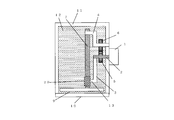
- FIG. 1 is a diagram showing an ultrasonic probe according to an embodiment of the present invention.
- FIG. 1A is a front view of the ultrasonic probe.
- FIG. 1B is a cross-sectional view taken along the line A-A ′ of the ultrasonic probe shown in FIG.
- the ultrasonic probe is connected to an ultrasonic diagnostic apparatus main body (not shown), and a drive electric signal is sent from the main body.
- the rotating shaft of the motor 1 fixed to the probe housing 11 or, if the motor 1 is provided with a speed reducing mechanism, the output shaft of the speed reducing mechanism (hereinafter referred to as “rotating shaft 2”) is used as the probe housing. It penetrates the body 11.
- the rotating shaft 2 rotates forward or reverses by a predetermined angle in an acoustic coupling liquid 12 that helps propagation of ultrasonic waves sealed by an oil seal (not shown), a window 10, a probe housing 11, and the like.
- the first arm 3 having one end fixed to the rotating shaft 2 performs a swinging motion by rotating forward or reverse by a predetermined angle around the rotating shaft 2 as the rotating shaft 2 rotates. .
- the first arm 3 is partly fixed to the rotation shaft 2, is connected to a portion extending perpendicularly to the rotation shaft 2 and the other end of the portion, and is parallel to the rotation shaft 2 and Has a protrusion 13 extending in the opposite direction.
- the rotating shaft 2 may be a part of the first arm 3. That is, a part of the first arm 3 may be called the rotating shaft 2 fixed to the first arm 3.
- the protruding portion 13 may be a part of the first arm 3 or may be made of a member different from the first arm 3 and connected to the first arm 3.
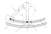
- the trajectory of the protrusion 13 when the first arm 3 performs a swinging motion with the rotation of the rotating shaft 2 is represented by a dotted line C in FIG.
- the second arm 4 is rotatably attached to the probe housing 11.
- a first gear 5 that is a rotation transmission unit is fixed to the rotary shaft 2
- a second gear 6 that is a rotation transmission unit is fixed to the second arm 4, and the first gear 5 and the second gear are fixed. 6 is engaged. That is, the first gear 5 and the second gear 6 mesh with each other, and the second arm 4 swings in the opposite direction simultaneously with the first arm 3 as the rotary shaft 2 rotates.
- the first gear 5 and the second gear 6 have the same size, but may have different sizes.
- a third arm 7 is rotatably attached to the second arm 4 at a tip portion different from the contact point of the second arm 4 with the probe housing 11.
- the second arm 4 performs a swinging motion by rotating forward or reverse by a predetermined angle around the rotation axis of the second gear 6.
- the second arm 4 includes a first part that extends perpendicularly to the probe housing 11 from a contact point with the probe housing 11 and serves as a rotation axis of the second gear 6, and a first part.
- a second portion extending perpendicularly to the first portion, and a third portion extending in a direction opposite to the first portion in parallel with the first portion.
- the first portion of the second arm 4 is connected to the rotation center of the second gear 6. In the configuration shown in FIG.
- the first portion of the second arm 4 serves as the rotation shaft of the second gear 6, but the rotation shaft of the second gear 6 is composed of different members, and Two arms 4 may be connected. Further, the third part may be made of a member different from the second part and connected to the second part. That is, the first part of the second arm 4 may be called a rotation shaft fixed to the second arm 4.
- the protrusion 13 draws a trajectory represented by a dotted line C in FIG.
- the third arm 7 performs a swinging motion as the protrusion 13 moves.
- the second gear 6 rotates with the rotation of the rotating shaft 2
- the second arm 4 performs a swinging motion with the rotation of the rotating shaft of the second gear 6.
- FIG. (A) is represented by a dotted line D.
- FIG. 1A the state when the third arm 7 is in the vertical direction is indicated by a solid line.
- the third arm 7 swings left and right, and in FIG. 1A, the third arm 7 when it swings left is indicated by a dotted line.
- the ultrasonic element 9 is attached to the tip of the other end different from the contact point of the third arm 7 with the second arm 4.
- the ultrasonic element 9 can mutually convert an electric signal and an ultrasonic signal, and transmits the electric signal to the ultrasonic diagnostic apparatus main body via a flexible printed board (not shown).
- the first end side having a contact point with the second arm 4, and the second end to which the ultrasonic element 9 is attached.
- the second gear 6 to which the second arm 4 is connected is located on the first end side where the contact with the second arm 4 is present from the first gear 5.
- the third arm 7 is located at a position further away from the motor 1 than the first gear 5 in the direction in which the rotating shaft 2 extends.
- a portion extending perpendicularly to the rotation axis 2 of the first arm 3 is located between the first gear 5 and the third arm 7 in the direction in which the rotation axis 2 extends.
- the second portion of the second arm 4 is located between the first gear 5 and the second gear 6 and the third arm 7 in the direction in which the rotating shaft 2 extends.
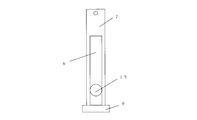
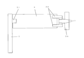
- FIG. 2 is a diagram showing an example of a sliding contact state between the third arm 7 and the protrusion 13 of the first arm 3 indicated by a solid line in FIG.
- a vertically long groove-shaped guide portion 8 is provided between the connecting portion between the fixed end of the third arm 7 to which the ultrasonic element 9 is attached and the second arm 4. Yes.
- the protrusion 13 extending in parallel with the rotation axis 2 of the first arm 3 is in sliding contact with the inner wall of the guide portion 8.
- the width of the groove of the guide portion 8 is substantially the same as the diameter of the sliding contact portion of the protruding portion 13.
- the groove of the guide portion 8 is a vertically long groove along the length direction of the third arm 7.
- the length of the groove is such that the third arm 7 moves when the third arm 7 swings left and right as shown in FIG. Any length that is possible is sufficient.
- the protrusion 13 positioned on the inner wall of the guide portion 8 of the third arm 7 is moved. Simultaneously with the rotational movement, it moves along the groove direction of the guide portion 8. That is, the protruding portion 13 of the first arm 3 is in sliding contact with the inner wall of the guide portion 8 so as to translate in the longitudinal direction of the third arm 7.
- the guide portion 8 described above is provided by forming a groove in a part of the third arm 7, but may be formed of a member different from the third arm 7.
- the second arm 4 that is rotated by the first arm 3 fixed to the rotating shaft 2 and the second gear 6 that meshes with the first gear 5 fixed to the rotating shaft 2 is the normal rotation of the rotating shaft 2 or By reversing, it always rotates in the opposite direction.
- the connection point of the second arm 4 and the third arm 7 moves with the rotation of the rotary shaft 2, and the protrusion 13 slides in the length direction of the third arm 7, so that the third arm 7
- the ultrasonic element 9 attached to 1 follows a trajectory different from the case where the connection point between the third arm 7 and the second arm 4 is a fixed rotation axis.
- first gear 5 and the second gear 6 may be arranged outside the probe housing 11. However, when the first gear 5 and the second gear 6 are arranged inside the probe housing 11 and the window 10, the axis passing through the probe housing 11 is only the rotary shaft 2. This is preferable because an oil seal or the like for sealing the acoustic coupling liquid 12 provided in the penetrating portion may be provided in one place. Further, it is not necessary to enclose the acoustic coupling liquid 12 in all the spaces surrounded by the probe housing 11 and the window 10, and if the acoustic coupling liquid 12 exists between the oscillating ultrasonic element 9 and the window. Good.
- the motor 1 is connected to the rotary shaft 2, but the motor 1 may be connected to the first portion of the second arm 4 described above.
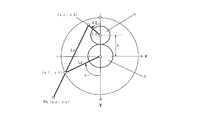
- FIG. 3 is a diagram for explaining the operation of the swinging mechanism including the first arm 3, the second arm 4, the third arm 7, the first gear 5, and the second gear 6.
- the rocking rotation will be described in detail with reference to FIG.
- the length of the first arm 3 is L1
- the length of the second arm 4 is L2
- the length of the third arm 7 is L3
- L be the distance between the rotation center of the arm 3 and the rotation center of the second arm 4.
- the swing angle ⁇ 1 of the first arm 3 is positive in the clockwise direction in FIG. 3 and negative in the counterclockwise direction.
- the swing angle ⁇ 2 of the second arm 4 is positive in the counterclockwise direction in FIG. 3 and negative in the clockwise direction.
- the positions where the angles ⁇ 1 and ⁇ 2 are 0 degrees are the positions below the vertical line in FIG.
- the angle ⁇ 2 is expressed by the following formula (1).
- the tip position (x1, y1) of the first arm 3 on the xy coordinates shown in FIG. 3 with the rotation center of the first arm 3 as the origin is expressed by the following equation (2).
- tip position (x2, y2) of the second arm 4 on the xy coordinates shown in FIG. 3 with the rotation center of the second arm 4 having the length L2 as the origin is expressed by the following equation (3). Is done.
- the tip position (x1, y1) of the first arm 3 is expressed by the following formula (4) when the rotation center of the second arm 4 is the origin.
- the tip position PA ( xa, ya) can be calculated as follows.
- PA (xa, ya) has the rotation center of the second arm 4 as the origin.
- the length of the line segment L3 is represented by the following formula (5).
- Equation (7) is substituted into Equation (5), and the tip position PA (xa, ya) of the third arm 7 is calculated.
- the length L1 of the first arm 3 is 15 mm
- the length L2 of the second arm 4 is 50 mm
- the length L3 of the third arm 7 is 60 mm
- the number of teeth of the gear 6 is made equal
- the distance L between the rotation center of the first arm 3 and the rotation center of the second arm 4 is 15 mm
- the first arm 3 is swung to ⁇ 45 degrees from the Y axis.
- the ultrasonic element 9 is attached to the tip of the third arm 7, in the example shown in FIG. 4, the ultrasonic element 9 is moved substantially horizontally in the x-axis direction within a range of ⁇ 40 mm. Can be made.
- the locus of the tip position PA of the third arm 7 shown in FIG. 4 is an example, and the lengths of L1, L2, L3, and L, and the gear ratio (number of teeth) of the first gear 5 and the second gear 6 are shown. By changing the ratio, the tip position PA of the third arm 7 can realize a desired locus.
- a first pulley 14 and a second pulley 15 are attached to the first arm 3 and the second arm 4 instead of the first gear 5 and the second gear 6, These two pulleys may be coupled by the belt 16.
- a series of belts 16 are wound around the first pulley 14 and the second pulley 15 so as to intersect between the first pulley 14 and the second pulley 15.
- the belt 16 causes the second pulley 15 to rotate in accordance with the rotation of the first pulley 14. If a steel belt is used as the belt 16, it is possible to reduce backlash that is likely to occur due to the coupling of gears.
- the protrusion 13 of the first arm 3 is connected to the third arm 7 so as to be able to move in parallel with the longitudinal direction of the third arm 7.
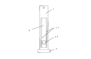
- FIG. 6 is a diagram illustrating an example of a sliding contact state between the groove-shaped guide portion 8 provided on the third arm 7 and the protrusion portion 13 provided on the tip of the first arm 3.
- the sliding contact state of the protrusion 13 may be configured as shown in FIG. 6 instead of FIG.
- the protruding portion 13 is positioned so as to be sandwiched between the groove-shaped guide portions 8.
- a low friction resin 17 made of a fluorine-based resin such as polytetrafluoroethylene is provided on both or one of the inner wall of the guide portion 8 and the protruding portion 13.
- the configuration with the coating is preferred. As a result, the frictional resistance when the side wall portion of the guide portion 8 and the surface of the projection portion 13 come into contact with each other is reduced.
- FIG. 7 is a view showing an example of a sliding contact state between the groove-shaped guide portion 8 provided on the third arm 7 and the projection portion 13 provided at the tip of the first arm 3.
- the sliding contact state of the protrusion 13 may be configured as shown in FIG. 7 instead of FIG. In the configuration shown in FIG. 7, the protrusion 13 is positioned so as to be sandwiched between the groove-shaped guide portions 8. Further, since the protrusion 13 slides more smoothly with respect to the guide portion 8, two or more bearings 18 are provided on the protrusion 13, and the two or more bearings 18 are in contact with both ends of the guide portion 8. preferable. Note that the low friction resin 17 may be coded on the inner wall of the groove-shaped guide portion 8.
- FIG. 8 is a diagram illustrating an example of a sliding contact state between the groove-shaped guide portion 8 provided on the third arm 7 and the protrusion portion 13 provided on the tip of the first arm 3.
- the sliding contact state of the protrusion 13 may be configured as shown in FIG. 8 instead of FIG.
- two or more bearings are provided on the rotating plate 25 such that the rotating plate 25 rotatably attached to the first arm 3 is rotated in one direction by an elastic body 19 such as a spring. 18 is rotatably attached. A force in a direction in which the bearing 18 is pushed against the inner wall of the groove-shaped guide portion 8 by the elastic body 19 is applied to the rotating plate 25, and the bearing 18 always contacts the inner wall of the guide portion 8.
- the variation in the width of the guide portion 8 and the arrangement interval of the two bearings 18 have a slight error with respect to the width of the guide portion 8, since rattling can be prevented.
- the inner wall of the groove-shaped guide portion 8 may be coated with the low friction resin 17.
- the first arm 3 fixed to the rotating shaft 2 rotates about the rotating shaft 2, so that the first arm 3 and the first arm 3
- the two arms 4 swing in opposite directions by the meshing of the first gear 5 and the second gear 6.
- the third arm 7 swings based on a position determined by the connecting portion with the second arm 4 and the guide portion 8 in which the protrusion 13 of the first arm 3 is slidably contacted.
- the motor 1 is rotationally driven to swing the first arm 3 and the second arm 4
- the ultrasonic element 9 attached to the distal end of the third arm 7 becomes one end of the third arm 7. Swing with a trajectory with a larger curvature than rocking around the center.
- FIG. 9 is a diagram showing another example of the sliding contact state of the protrusions 13 provided at the tips of the third arm 7 and the first arm 3.
- the sliding contact state of the protrusion 13 may be the configuration shown in FIG. 9 instead of the configuration shown in FIG.
- the protrusion 13 provided at the tip of the first arm 3 is two or more protrusions, and the third arm 7 is sandwiched between these two or more protrusions.
- both or one of the contact surfaces between the third arm 7 and the protruding portion 13 is made of, for example, a low fluorine resin.
- a configuration in which the friction resin 17 is coated is preferable. As a result, the frictional resistance when the third arm 7 and the surface of the protrusion 13 are in contact with each other is reduced.
- the groove-shaped guide portion 8 does not have to be provided on the third arm 7.
- FIG. 10 is a diagram showing another example of the sliding contact state of the protrusions 13 provided at the tips of the third arm 7 and the first arm 3.
- the sliding contact state of the protrusion 13 may be the configuration shown in FIG. 10 instead of the configuration shown in FIG.
- the protrusion 13 provided at the tip of the first arm 3 is two or more protrusions, and the third arm 7 is sandwiched between these two or more protrusions. Further, two or more bearings 18 are provided on the protrusion 13 to reduce sliding resistance.
- the groove-shaped guide portion 8 may not be provided on the third arm 7.
- the surface of the third arm 7 may be coated with the low friction resin 17.
- FIG. 11 is a diagram showing another example of the sliding contact state of the protrusions 13 provided at the tips of the third arm 7 and the first arm 3.
- the sliding contact state of the protrusion 13 may be the configuration shown in FIG. 11 instead of the configuration shown in FIG.
- a bearing 18 is rotatably connected to one of the protrusions 13 of the first arm 3, and the elastic body 19 is connected so as to pull the bearing 18 connected to the other protrusion 13.
- the third arm 7 is sandwiched between the two bearings 18 by the tensile stress of the elastic body 19.
- the surface of the third arm 7 may be coated with the low friction resin 17.
- the first arm 3 fixed to the rotating shaft 2 rotates around the rotating shaft 2, thereby The arm 3 and the second arm 4 oscillate in opposite directions by the meshing of the first gear 5 and the second gear 6.
- the third arm 7 performs a swinging motion in accordance with the connection with the second arm 4 and the slidable contact that can be translated by the projection 13 of the first arm 3. Therefore, when the motor 1 is rotationally driven to swing the first arm 3 and the second arm 4, the ultrasonic element 9 attached to the distal end of the third arm 7 becomes one end of the third arm 7. Swing with a trajectory with a larger curvature than rocking around the center. Further, since both side surfaces of the third arm 7 are sandwiched between the protrusions 13, the third arm 7 can be easily processed to a uniform width with high accuracy by grinding or the like.
- FIG. 12 is a diagram showing another example of the sliding contact state of the protrusions 13 provided at the tips of the third arm 7 and the first arm 3.
- the sliding contact state of the protrusion 13 may be the configuration shown in FIG. 12 instead of the configuration shown in FIG.
- the protrusion 13 provided at the tip of the first arm 3 has a slide bearing 20.
- the slide bearing 20 has a structure that can slide in the longitudinal direction of the third arm 7. By connecting the first arm 3 to the slide bearing 20 so as to be rotatable, it is possible to realize a swinging mechanism having a small sliding resistance and a smooth backlash.
- the groove-shaped guide portion 8 may not be provided on the third arm 7.
- the first arm 3 fixed to the rotating shaft 2 rotates around the rotating shaft 2, so that the first arm 3 and the second arm 4 are connected to the first gear 5.
- the second gear 6 are engaged with each other to swing in opposite directions.
- the third arm 7 performs a swinging motion according to the connection with the second arm 4 and the sliding contact that can be translated by the slide bearing 20. Therefore, when the motor 1 is rotationally driven to swing the first arm 3 and the second arm 4, the ultrasonic element 9 attached to the distal end of the third arm 7 becomes one end of the third arm 7. Swing with a trajectory with a larger curvature than rocking around the center. In addition, it is possible to reduce the sliding resistance and realize a smooth movement with little backlash at a low cost. Further, if a bearing is used as a means for rotatably fixing the slide bearing 20 to the protrusion 13 of the first arm 3, a smoother operation and a mechanical load can be reduced.
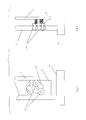
- FIG. 13 is a diagram for explaining an example of the attachment structure of the ultrasonic element 9 and its operation.
- the ultrasonic element 9 is attached to the tip of the third arm 7 so as to be rotatable about the element rotation shaft 21.
- the ultrasonic element 9 is provided with a guide shaft 22 that is integral with the ultrasonic element 9 and is rotatable with respect to the tip of the third arm 7.
- the guide shaft 22 is in sliding contact with a groove-like rail 23 provided in the probe housing 11 or the window 10. For this reason, it is possible to incline the ultrasonic element 9 that transmits and receives ultrasonic waves in a desired direction with respect to the living body.
- the guide shaft 22 is fixed to the ultrasonic element 9, the direction of the ultrasonic element 9 when the third arm 7 swings is determined by the guide shaft 22. That is, since the ultrasonic element 9 can always be tilted parallel to the window 10, the ultrasonic wave radiated from the ultrasonic element 9 can always be emitted perpendicularly to the window 10.
- the groove-like rail 23 may be designed such that a part of the probe housing 11 or the window 10 is rail-shaped, or a rail-shaped part may be attached to the probe housing 11 or the window 10. Further, when the direction of the ultrasonic element 9 is set to the same direction as the inclination of the third arm 7, the ultrasonic element 9 may be fixed to the third arm 7. In this case, it is not necessary to provide the element rotating shaft 21, the guide shaft 22, and the rail 23 described above.
- FIG. 14 is a diagram for explaining an example of the attachment structure of the ultrasonic element 9 and the operation thereof.
- the ultrasonic element 9 is attached to the tip of the third arm 7 so as to be rotatable about the element rotation shaft 21.
- the ultrasonic element 9 is provided with two or more guide shafts 22 that are integrated with the ultrasonic element 9 and are rotatable with respect to the tip of the third arm 7.
- One of the two guide shafts 22 is fixed to the ultrasonic element 9, and the other is connected to the guide shaft 22 fixed to the ultrasonic element 9 by a second elastic body 24 such as a spring.
- the two guide shafts 22 are slidably brought into contact with the groove-like rail 23 by the repulsive force of the elastic body 24.
- FIG. 15 is a diagram for explaining an example of the attachment structure of the ultrasonic element 9 and the operation thereof.
- the ultrasonic element 9 is attached to the tip of the third arm 7 so as to be rotatable about the element rotation shaft 21.
- the ultrasonic element 9 is provided with two or more guide shafts 22 that are integrated with the ultrasonic element 9 and are rotatable with respect to the tip of the third arm 7.
- the two guide shafts 22 are in sliding contact so that one of the two guide shafts 22 is fixed to the ultrasonic element 9 and the other is sandwiched between the convex rails 23 by the suction force of the second elastic body 24 such as a spring. .
- the convex rail 23 can be realized relatively easily when realized by machining or molding.
- FIG. 16 is a diagram for explaining an example of the attachment structure of the ultrasonic element 9 and its operation.
- the ultrasonic element 9 is attached to the tip of the third arm 7 so as to be rotatable about the element rotation shaft 21.
- the ultrasonic element 9 is provided with two or more guide shafts 22 that are integrated with the ultrasonic element 9 and are rotatable with respect to the tip of the third arm 7.
- One of the two guide shafts 22 is fixed to the ultrasonic element 9, and the other is connected to the guide shaft 22 fixed to the ultrasonic element 9 by a second elastic body 24 such as a spring.
- the two guide shafts 22 are in sliding contact with the convex rail 23 by the suction force of the elastic body 24.
- a bearing 18 is provided at each end of the guide shaft 22.
- FIG. 17 is a diagram for explaining an example of the attachment structure of the ultrasonic element 9 and the operation thereof.
- the ultrasonic element 9 is attached to the tip of the third arm 7 so as to be rotatable about the element rotation shaft 21.
- the ultrasonic element 9 is provided with two or more guide shafts 22 that are integrated with the ultrasonic element 9 and are rotatable with respect to the tip of the third arm 7.
- the two guide shafts 22 are configured to be in sliding contact so that the convex rail 23 is sandwiched between them, and the friction resistance when the surface of the guide shaft 22 and the rail 23 comes into contact with one or both of the guide shaft 22 and the rail 23 is reduced.
- a low friction material 17 such as a fluorine resin is attached.
- the ultrasonic probe itself can be reduced in size while maintaining a wide scanning area, the ultrasonic probe can be easily adhered to a living body.
- the ultrasonic element 9 may be a single element and may be a mechanical ultrasonic probe that mechanically scans by a swing mechanism. Further, the ultrasonic element 9 is an electronic scanning type ultrasonic element, and by arranging the ultrasonic element so as to perform electronic scanning in a direction orthogonal to the mechanical swinging direction, scanning by electronic scanning and mechanical An ultrasonic probe that acquires a three-dimensional ultrasonic image by scanning with rocking may be used.
- the present invention in particular, by mechanically translating or oscillating in a direction orthogonal to the electrical scanning direction of the array type element that obtains a tomographic image by arranging and electrically scanning piezoelectric elements in a strip shape, It is suitable for a small hand-held ultrasonic probe for obtaining a three-dimensional tomographic image in a living body.
- a device that is small and light-weighted not only in a hand-held ultrasonic probe but also in an ultrasonic device that scans a wide range of the body surface with a stationary type.
Landscapes
- Health & Medical Sciences (AREA)
- Life Sciences & Earth Sciences (AREA)
- Engineering & Computer Science (AREA)
- Physics & Mathematics (AREA)
- Medical Informatics (AREA)
- Animal Behavior & Ethology (AREA)
- Radiology & Medical Imaging (AREA)
- Nuclear Medicine, Radiotherapy & Molecular Imaging (AREA)
- Biomedical Technology (AREA)
- Heart & Thoracic Surgery (AREA)
- Biophysics (AREA)
- Molecular Biology (AREA)
- Surgery (AREA)
- Pathology (AREA)
- General Health & Medical Sciences (AREA)
- Public Health (AREA)
- Veterinary Medicine (AREA)
- Acoustics & Sound (AREA)
- Multimedia (AREA)
- Ultra Sonic Daignosis Equipment (AREA)
- Mechanical Engineering (AREA)
Abstract
Description
さらに第2のアームは、第1の先端と、第1の先端とは異なる第2の先端と、を有し、第1の先端は、探触子筐体に対して回転可能に接続され、第2の先端は、第3のアームの第1の端部に接続され、第3のアームのうち、第1の端部とは異なる第2の端部の先端に超音波素子が接続され、第3のアームのうち、第1の端部と超音波素子の間に突起部が位置していることを特徴とする。
さらに第3のアームには、第3のアームの長手方向にガイド部が設けられており、突起部がガイド部に摺接していることを特徴とする。
さらにガイド部は、第3のアームの少なくとも一部を溝形状とした部分であり、突起部が溝形状のガイド部の内壁と摺接していることを特徴とする。
さらに溝形状のガイド部の内壁と突起部のうち少なくとも一方に、溝形状のガイド部の内壁と突起部の表面が接触するときの摩擦抵抗が低くなる材料が設けられたことを特徴とする。
さらに突起部に、突起部に対して回転可能なベアリングを設けたことを特徴とする。
さらに第1のアームに取り付けられた弾性体と、弾性体により一方向に回転する力が加えられる回転可能な回転板と、回転板に回転可能に設けられた少なくとも二つのベアリングと、を有し、ベアリングが、溝部のガイド部の内壁と接触するように構成されたことを特徴とする。
さらに突起部は、少なくとも二つの突起部を含み、少なくとも二つの突起部が、第3のアームを挟持することを特徴とする。
さらに少なくとも二つの突起部と第3のアームの少なくとも一方に、少なくとも二つの突起部の表面と第3のアームの表面が接触するときの摩擦抵抗が低くなる材料が設けられたことを特徴とする。
さらに少なくとも二つの突起部にベアリングを設けたことを特徴とする。
さらに少なくとも二つの突起部は弾性体により引き合うことを特徴とする。
さらに突起部は第3のアームに対して摺動可能なスライド軸受けを含むことを特徴とする。
さらに第1の回転伝達部と第2の回転伝達部がギヤで構成されていることを特徴とする。
さらに第1の回転伝達部と第2の回転伝達部はそれぞれプーリで構成され、第1の回転伝達部と第2の回転伝達部の間で交差するように、第1の回転伝達部と第2の回転伝達部の周りにベルトが巻きつけられていることを特徴とする。
さらに第1の回転伝達部と第2の回転伝達部は探触子筐体内に収納されたことを特徴とする。
さらに超音波素子は第3のアームに対して回転可能に接続され、超音波素子にはガイド軸が接続され、探触子筐体の内部にレールを備え、ガイド軸は前記レールに沿って移動可能なように接触していることを特徴とする。
さらにレールは溝状であり、ガイド軸は溝状の溝部の中に位置することを特徴とする。
さらに弾性体を介してガイド軸と接続される第2のガイド軸を備え、ガイド軸及び第2のガイド軸は、レールに挟持されていることを特徴とする。
さらにレールは凸状であり、弾性体を介してガイド軸と接続される第2のガイド軸を備え、ガイド軸及び第2のガイド軸は、レールの凸部を挟持していることを特徴とする。
さらにガイド軸のうちレールと接触する部分にはベアリングが設けられたことを特徴とする。
さらにガイド軸とレールの少なくとも一方に、ガイド軸とレールが接触するときの摩擦抵抗が低くなる樹脂材料が設けられたことを特徴とする。
超音波素子は電子走査型素子であって、超音波素子の電子走査と直交する方向に超音波素子が機械的に揺動することを特徴とする。







2 回転軸
3 第1のアーム
4 第2のアーム
5 第1のギヤ
6 第2のギヤ
7 第3のアーム
8 ガイド部
9 超音波素子
10 ウインドウ
11 探触子筐体
12 音響結合液体
13 突起部
14 第1のプーリ
15 第2のプーリ
16 ベルト
17 低摩擦樹脂
18 ベアリング
19 弾性体
20 スライド軸受け
21 素子回転軸
22 ガイド軸
23 レール
24 第2の弾性体
25 回転板
Claims (22)
- 音響結合液体を内部に封止した探触子筐体と、
前記探触子筐体に固定したモータと、
第1の回転軸に固定され、前記第1の回転軸の回転に伴って回転する第1のアームと、
前記第1のアームに設けられた突起部と、
前記第1の回転軸に取り付けられた第1の回転伝達部と、
前記第1の回転伝達部に係合され、前記第1の回転伝達部による回転によって、当該回転とは逆方向に回転する第2の回転伝達部と、
前記第2の回転伝達部に固定され、前記第2の回転伝達部の回転の軸となる第2の回転軸と、
前記第2の回転軸に固定され、前記第2の回転軸の回転に伴って回転する第2のアームと、
前記第2のアームに対して回転可能に取り付けられた第3のアームと、
前記第3のアームに接続された超音波素子と、を有し、
前記第1のアーム、前記第2のアーム及び前記第3のアームは前記探触子筐体内に位置し、
前記モータは、前記第1の回転軸又は前記第2の回転軸に接続され、
前記モータに接続された前記第1の回転軸又は前記第2の回転軸は、前記モータの回転に伴って回転し、
前記第1のアームに設けられた前記突起部は、前記第3のアームの長手方向に摺動可能に、前記第3のアームに接続されている超音波探触子。 - 前記第2のアームは、第1の先端と、前記第1の先端とは異なる第2の先端と、を有し、
前記第1の先端は、前記探触子筐体に対して回転可能に接続され、
前記第2の先端は、前記第3のアームの第1の端部に接続され、
前記第3のアームのうち、前記第1の端部とは異なる第2の端部の先端に前記超音波素子が接続され、
前記第3のアームのうち、前記第1の端部と前記超音波素子の間に前記突起部が位置している請求項1に記載の超音波探触子。 - 前記第3のアームには、前記第3のアームの長手方向にガイド部が設けられており、
前記突起部が前記ガイド部に摺接している請求項1又は2に記載の超音波探触子。 - 前記ガイド部は、前記第3のアームの少なくとも一部を溝形状とした部分であり、
前記突起部が前記溝形状のガイド部の内壁と摺接している請求項3に記載の超音波探触子。 - 前記溝形状のガイド部の内壁と前記突起部のうち少なくとも一方に、前記溝形状のガイド部の内壁と前記突起部の表面が接触するときの摩擦抵抗が低くなる材料が設けられた請求項4に記載の超音波探触子。
- 前記突起部に、前記突起部に対して回転可能なベアリングを設けた請求項1~5のいずれか1項に記載の超音波探触子。
- 前記第1のアームに取り付けられた弾性体と、
前記弾性体により一方向に回転する力が加えられる回転可能な回転板と、
前記回転板に回転可能に設けられた少なくとも二つのベアリングと、を有し、
前記ベアリングが、前記溝形状のガイド部の内壁と接触するように構成された請求項4~6のいずれか1項に記載の超音波探触子。 - 前記突起部は、少なくとも二つの突起部を含み、
前記少なくとも二つの突起部が、前記第3のアームを挟持する請求項1又は2に記載の超音波探触子。 - 前記少なくとも二つの突起部と前記第3のアームの少なくとも一方に、前記少なくとも二つの突起部の表面と前記第3のアームの表面が接触するときの摩擦抵抗が低くなる材料が設けられた請求項8に記載の超音波探触子。
- 前記少なくとも二つの突起部にベアリングを設けた請求項8又は9に記載の超音波探触子。
- 前記少なくとも二つの突起部は弾性体により引き合うことを特徴とする請求項10に記載の超音波探触子。
- 前記突起部は、前記第3のアームに対して摺動可能なスライド軸受けを含む請求項1又は2に記載の超音波探触子。
- 前記第1の回転伝達部と前記第2の回転伝達部がギヤで構成されている請求項1~12のいずれか1項に記載の超音波探触子。
- 前記第1の回転伝達部と前記第2の回転伝達部はそれぞれプーリで構成され、
前記第1の回転伝達部と前記第2の回転伝達部の間で交差するように、前記第1の回転伝達部と前記第2の回転伝達部の周りにベルトが巻きつけられた請求項1~12のいずれか1項に記載の超音波探触子。 - 前記第1の回転伝達部と前記第2の回転伝達部は前記探触子筐体内に収納された請求項1~14のいずれか1項に記載の超音波探触子。
- 前記超音波素子は前記第3のアームに対して回転可能に接続され、
前記超音波素子にはガイド軸が接続され、
前記探触子筐体の内部にレールを備え、
前記ガイド軸は前記レールに沿って移動可能なように接触している請求項1~15のいずれか1項に記載の超音波探触子。 - 前記レールは溝状であり、
前記ガイド軸は前記溝状の溝部の中に位置する請求項16に記載の超音波探触子。 - 弾性体を介して前記ガイド軸と接続される第2のガイド軸を備え、
前記ガイド軸及び前記第2のガイド軸は、前記レールに挟持されている請求項16又は17に記載の超音波探触子。 - 前記レールは凸状であり、
弾性体を介して前記ガイド軸と接続される第2のガイド軸を備え、
前記ガイド軸及び前記第2のガイド軸は、前記レールの凸部を挟持している請求項16に記載の超音波探触子。 - 前記ガイド軸のうち前記レールと接触する部分にはベアリングが設けられた請求項16~19のいずれか1項に記載の超音波探触子。
- 前記ガイド軸と前記レールの少なくとも一方に、前記ガイド軸と前記レールが接触するときの摩擦抵抗が低くなる樹脂材料が設けられた請求項16~20のいずれか1項に記載の超音波探触子。
- 前記超音波素子は電子走査型素子であって、
前記超音波素子の電子走査と直交する方向に前記超音波素子が機械的に揺動する請求項1~21のいずれか1項に記載の超音波探触子。
Priority Applications (3)
| Application Number | Priority Date | Filing Date | Title |
|---|---|---|---|
| CN201380038627.XA CN104602609B (zh) | 2012-07-24 | 2013-07-19 | 超声波探头 |
| JP2014526752A JP6183365B2 (ja) | 2012-07-24 | 2013-07-19 | 超音波探触子 |
| US14/417,069 US9808223B2 (en) | 2012-07-24 | 2013-07-19 | Ultrasound probe having first and second rotation transmission sections |
Applications Claiming Priority (2)
| Application Number | Priority Date | Filing Date | Title |
|---|---|---|---|
| JP2012-163376 | 2012-07-24 | ||
| JP2012163376 | 2012-07-24 |
Publications (1)
| Publication Number | Publication Date |
|---|---|
| WO2014017059A1 true WO2014017059A1 (ja) | 2014-01-30 |
Family
ID=49996887
Family Applications (1)
| Application Number | Title | Priority Date | Filing Date |
|---|---|---|---|
| PCT/JP2013/004426 Ceased WO2014017059A1 (ja) | 2012-07-24 | 2013-07-19 | 超音波探触子 |
Country Status (4)
| Country | Link |
|---|---|
| US (1) | US9808223B2 (ja) |
| JP (1) | JP6183365B2 (ja) |
| CN (1) | CN104602609B (ja) |
| WO (1) | WO2014017059A1 (ja) |
Families Citing this family (3)
| Publication number | Priority date | Publication date | Assignee | Title |
|---|---|---|---|---|
| CN108065964B (zh) * | 2018-01-16 | 2021-04-20 | 中国科学院苏州生物医学工程技术研究所 | 一种超声成像方法、装置、设备及超声成像探头 |
| KR102749838B1 (ko) * | 2019-03-22 | 2025-01-07 | 삼성메디슨 주식회사 | 초음파 영상 장치 및 그 제어 방법 |
| CN113740419A (zh) * | 2021-08-31 | 2021-12-03 | 西安热工研究院有限公司 | 一种用于涡流检测的内穿式探头 |
Citations (2)
| Publication number | Priority date | Publication date | Assignee | Title |
|---|---|---|---|---|
| WO2008010558A1 (en) * | 2006-07-20 | 2008-01-24 | Panasonic Corporation | Ultrasonic probe |
| WO2010064415A1 (ja) * | 2008-12-02 | 2010-06-10 | パナソニック株式会社 | 超音波探触子 |
Family Cites Families (11)
| Publication number | Priority date | Publication date | Assignee | Title |
|---|---|---|---|---|
| DE3778179D1 (de) * | 1986-01-30 | 1992-05-21 | Matsushita Electric Industrial Co Ltd | Ultraschallwandler fuer medizinische diagnostik. |
| US5097838A (en) * | 1989-04-27 | 1992-03-24 | Olympus Optical Co., Ltd. | Ultrasonic endoscope |
| JP3490391B2 (ja) * | 2000-11-17 | 2004-01-26 | 松下電器産業株式会社 | 超音波探触子 |
| JP3490390B2 (ja) * | 2000-11-17 | 2004-01-26 | 松下電器産業株式会社 | 超音波探触子およびその製造方法 |
| JP4611909B2 (ja) * | 2006-02-21 | 2011-01-12 | 日本電波工業株式会社 | 短軸遥動型超音波探触子 |
| JP4668110B2 (ja) * | 2006-03-30 | 2011-04-13 | 日本電波工業株式会社 | 超音波探触子 |
| US20100076316A1 (en) * | 2006-07-25 | 2010-03-25 | Nihon Dempa Kogyo Co., Ltd. | Ultrasonic probe |
| JP4584321B2 (ja) | 2008-02-19 | 2010-11-17 | 日本電波工業株式会社 | 超音波探触子 |
| KR101363783B1 (ko) * | 2008-11-14 | 2014-02-17 | 엘지디스플레이 주식회사 | 임프린팅용 감광성 수지 조성물 및 기판 상에 유기막을 형성하는 방법 |
| WO2010131479A1 (ja) * | 2009-05-14 | 2010-11-18 | パナソニック株式会社 | 超音波探触子とこれを用いた超音波診断装置 |
| CN102551792B (zh) * | 2010-12-27 | 2015-04-08 | 深圳迈瑞生物医疗电子股份有限公司 | 一种3d机械探头 |
-
2013
- 2013-07-19 US US14/417,069 patent/US9808223B2/en not_active Expired - Fee Related
- 2013-07-19 WO PCT/JP2013/004426 patent/WO2014017059A1/ja not_active Ceased
- 2013-07-19 JP JP2014526752A patent/JP6183365B2/ja not_active Expired - Fee Related
- 2013-07-19 CN CN201380038627.XA patent/CN104602609B/zh not_active Expired - Fee Related
Patent Citations (2)
| Publication number | Priority date | Publication date | Assignee | Title |
|---|---|---|---|---|
| WO2008010558A1 (en) * | 2006-07-20 | 2008-01-24 | Panasonic Corporation | Ultrasonic probe |
| WO2010064415A1 (ja) * | 2008-12-02 | 2010-06-10 | パナソニック株式会社 | 超音波探触子 |
Also Published As
| Publication number | Publication date |
|---|---|
| CN104602609B (zh) | 2016-12-14 |
| US9808223B2 (en) | 2017-11-07 |
| US20150201903A1 (en) | 2015-07-23 |
| CN104602609A (zh) | 2015-05-06 |
| JP6183365B2 (ja) | 2017-08-23 |
| JPWO2014017059A1 (ja) | 2016-07-07 |
Similar Documents
| Publication | Publication Date | Title |
|---|---|---|
| CN101966089B (zh) | 超声波探测器 | |
| CN102238914B (zh) | 超声波探头 | |
| JP6059432B2 (ja) | 3次元撮像超音波プローブ | |
| JP5416627B2 (ja) | 3次元超音波探触子 | |
| JP2012050824A (ja) | 多焦点超音波のシステムおよび方法 | |
| JP4584321B2 (ja) | 超音波探触子 | |
| US20100076316A1 (en) | Ultrasonic probe | |
| JP6183365B2 (ja) | 超音波探触子 | |
| KR101068040B1 (ko) | 3차원 초음파 스캐너 | |
| CN101601592B (zh) | 超声波探头以及超声波诊断装置 | |
| KR20130011238A (ko) | 단일 모터를 이용한 초음파 트랜스듀서 구동 장치 | |
| KR20160140837A (ko) | 초음파 트랜스듀서 및 그 작동 방법 | |
| CN104367345B (zh) | 一种超声探头组件 | |
| CN104921754A (zh) | 三维超声波探头 | |
| JP4472411B2 (ja) | 超音波探触子 | |
| JP4468480B1 (ja) | 超音波探触子 | |
| JP6321478B2 (ja) | メカニカル3d超音波探触子 |
Legal Events
| Date | Code | Title | Description |
|---|---|---|---|
| 121 | Ep: the epo has been informed by wipo that ep was designated in this application |
Ref document number: 13823443 Country of ref document: EP Kind code of ref document: A1 |
|
| ENP | Entry into the national phase |
Ref document number: 2014526752 Country of ref document: JP Kind code of ref document: A |
|
| WWE | Wipo information: entry into national phase |
Ref document number: 14417069 Country of ref document: US |
|
| NENP | Non-entry into the national phase |
Ref country code: DE |
|
| 122 | Ep: pct application non-entry in european phase |
Ref document number: 13823443 Country of ref document: EP Kind code of ref document: A1 |