WO2014016908A1 - Fastener element for slide fastener - Google Patents
Fastener element for slide fastener Download PDFInfo
- Publication number
- WO2014016908A1 WO2014016908A1 PCT/JP2012/068712 JP2012068712W WO2014016908A1 WO 2014016908 A1 WO2014016908 A1 WO 2014016908A1 JP 2012068712 W JP2012068712 W JP 2012068712W WO 2014016908 A1 WO2014016908 A1 WO 2014016908A1
- Authority
- WO
- WIPO (PCT)
- Prior art keywords
- fastener
- fastener element
- layer
- light
- light transmissive
- Prior art date
Links
Images


Classifications
-
- C—CHEMISTRY; METALLURGY
- C23—COATING METALLIC MATERIAL; COATING MATERIAL WITH METALLIC MATERIAL; CHEMICAL SURFACE TREATMENT; DIFFUSION TREATMENT OF METALLIC MATERIAL; COATING BY VACUUM EVAPORATION, BY SPUTTERING, BY ION IMPLANTATION OR BY CHEMICAL VAPOUR DEPOSITION, IN GENERAL; INHIBITING CORROSION OF METALLIC MATERIAL OR INCRUSTATION IN GENERAL
- C23C—COATING METALLIC MATERIAL; COATING MATERIAL WITH METALLIC MATERIAL; SURFACE TREATMENT OF METALLIC MATERIAL BY DIFFUSION INTO THE SURFACE, BY CHEMICAL CONVERSION OR SUBSTITUTION; COATING BY VACUUM EVAPORATION, BY SPUTTERING, BY ION IMPLANTATION OR BY CHEMICAL VAPOUR DEPOSITION, IN GENERAL
- C23C14/00—Coating by vacuum evaporation, by sputtering or by ion implantation of the coating forming material
- C23C14/0015—Coating by vacuum evaporation, by sputtering or by ion implantation of the coating forming material characterized by the colour of the layer
-
- A—HUMAN NECESSITIES
- A44—HABERDASHERY; JEWELLERY
- A44B—BUTTONS, PINS, BUCKLES, SLIDE FASTENERS, OR THE LIKE
- A44B19/00—Slide fasteners
- A44B19/10—Slide fasteners with a one-piece interlocking member on each stringer tape
- A44B19/12—Interlocking member in the shape of a continuous helix
-
- A—HUMAN NECESSITIES
- A44—HABERDASHERY; JEWELLERY
- A44B—BUTTONS, PINS, BUCKLES, SLIDE FASTENERS, OR THE LIKE
- A44B19/00—Slide fasteners
- A44B19/24—Details
-
- C—CHEMISTRY; METALLURGY
- C23—COATING METALLIC MATERIAL; COATING MATERIAL WITH METALLIC MATERIAL; CHEMICAL SURFACE TREATMENT; DIFFUSION TREATMENT OF METALLIC MATERIAL; COATING BY VACUUM EVAPORATION, BY SPUTTERING, BY ION IMPLANTATION OR BY CHEMICAL VAPOUR DEPOSITION, IN GENERAL; INHIBITING CORROSION OF METALLIC MATERIAL OR INCRUSTATION IN GENERAL
- C23C—COATING METALLIC MATERIAL; COATING MATERIAL WITH METALLIC MATERIAL; SURFACE TREATMENT OF METALLIC MATERIAL BY DIFFUSION INTO THE SURFACE, BY CHEMICAL CONVERSION OR SUBSTITUTION; COATING BY VACUUM EVAPORATION, BY SPUTTERING, BY ION IMPLANTATION OR BY CHEMICAL VAPOUR DEPOSITION, IN GENERAL
- C23C14/00—Coating by vacuum evaporation, by sputtering or by ion implantation of the coating forming material
- C23C14/06—Coating by vacuum evaporation, by sputtering or by ion implantation of the coating forming material characterised by the coating material
- C23C14/08—Oxides
- C23C14/083—Oxides of refractory metals or yttrium
-
- Y—GENERAL TAGGING OF NEW TECHNOLOGICAL DEVELOPMENTS; GENERAL TAGGING OF CROSS-SECTIONAL TECHNOLOGIES SPANNING OVER SEVERAL SECTIONS OF THE IPC; TECHNICAL SUBJECTS COVERED BY FORMER USPC CROSS-REFERENCE ART COLLECTIONS [XRACs] AND DIGESTS
- Y10—TECHNICAL SUBJECTS COVERED BY FORMER USPC
- Y10T—TECHNICAL SUBJECTS COVERED BY FORMER US CLASSIFICATION
- Y10T24/00—Buckles, buttons, clasps, etc.
- Y10T24/25—Zipper or required component thereof
- Y10T24/2518—Zipper or required component thereof having coiled or bent continuous wire interlocking surface
Definitions
- the present invention relates to a slide fastener. More specifically, the present invention relates to a fastener element for a slide fastener (hereinafter referred to as a fastener element) to which a decoration is added, and a slide fastener including the element.
- a fastener element for a slide fastener (hereinafter referred to as a fastener element) to which a decoration is added, and a slide fastener including the element.
- JP 2001-178508 A discloses a fastener element in which a metal coating layer is formed, and the upper surface excluding the outer surface of the fastener element that is in sliding contact with the guide flange. By forming the coating on the metal coating layer, the phenomenon that the metal coating layer is scraped off and the metal powder is scattered is prevented.
- the fastener elements obtained by the prior art have a very simple appearance from the viewpoint of decorativeness, and it was impossible to express various colors and patterns by the coating. Further, when a coating is formed to improve the decorativeness as in the prior art, problems such as peeling or cracking of the coating have occurred if it is continuously used.
- An object of the present invention is to provide a fastener element whose color and pattern are variously changed depending on an observation angle. Another object of the present invention is to provide a fastener element that is less likely to cause peeling and cracking of a decorative coating.
- the present invention provides a fastener element having the following characteristics: (1) A coil-shaped fastener element for a slide fastener to be attached to a fastener tape,
- the fastener element includes a meshing head, an upper leg, a lower leg, and an inversion part that connects the upper leg and the lower leg.
- a coating including at least one light transmissive layer is formed on at least the upper leg;
- the layer thickness of the light-transmitting layer is formed so as to gradually decrease from a substantially top portion of the upper leg portion toward the fastener tape side,
- the thickness of the substantially top portion is about 50 to about 1500 nm at the maximum (in some cases, excluding the resin film thickness (not including the resin top coat), the maximum is about 50 to about 1500 nm), Fastener element for slide fastener.
- the light transmissive layer includes at least two light transmissive layers stacked, and light is reflected at at least one interface formed by the at least two light transmissive layers.
- the fastener element for slide fasteners as described in (1) or (2).
- the light transmissive layer is formed by laminating three or more light transmissive layers, and laminated so that the relative refractive index of two adjacent layers alternately becomes high / low.
- the fastener element for a slide fastener according to any one of (1) to (3), which is formed.
- the light-transmitting layer is a dielectric (e.g., TiO 2, Ta 2 O 5 , Nb 2 O 5, ZrO 2, HfO 2, Sb 2 O 3, CeO 2, ZnO, AlN, La 2 O 3 , Gd 2 O 3 , Al 2 O 3 , SiO 2 , MgF 2 , MgO, Si 3 N 4, etc., and the material may not be a stoichiometric ratio).
- Conductive compounds, colored compounds ITO (In 2 O 3 : SnO 2 (5-10%)), SnO 2 , In 2 O 3 , TiN, Cr 2 O 3 , TiC, ZrC, NbC, TaC
- the material may not have a stoichiometric ratio) or the fastener element for a slide fastener according to the above (6), wherein the layer thickness of the layer containing metal / semiconductor is 100 nm or less.
- a layer containing metal (including a semiconductor) as a material is between the coating and the upper leg.
- a slide fastener comprising the fastener element according to any one of (1) to (11) above.
- the fastener element of the present invention since the fastener element of the present invention has a light-transmitting thin film (layer) at the outer peripheral portion of the upper leg portion to be visually recognized, an interference pattern can be formed.
- the film thickness layer thickness
- the film thickness is formed so as to gradually decrease, different interference patterns formed with different film thicknesses can be obtained depending on the observation angle. it can.
- the film thickness is in an appropriate range, cracks and the like are hardly generated.
- the fastener element of the present invention has a structure in which the edge of the outer peripheral direction of the film is formed to extend beyond the center line in the horizontal direction of the cross section toward the fastener tape, and therefore the film is less likely to peel. .
- the fastener element of the present invention forms an interface when the coating includes at least two light transmissive layers as a laminate.
- Various colors and complex interference patterns can be formed by the reflected light from the interface.
- a high refractive index layer and a low refractive index layer are alternately laminated, so that reflected light from a plurality of interfaces can be obtained, thereby forming a more complicated interference pattern. Can do.
- the fastener element of the present invention can enhance a specific color tone by making at least one of the light transmissive layers a colored layer.
- the fastener element of the present invention can improve the surface durability by having a layer containing a resin as a material as the outermost layer.
- the fastener element of the present invention can enhance the color tone due to interference of reflected light by forming a metal layer as a base layer formed under the coating.
- the slide fastener of the present invention is provided with the above-described fastener element, so that it is possible to obtain a hue (color tone varies depending on the observation angle) that could not be obtained by the prior art. Furthermore, since it can be semi-reflected while showing the color of the background, a complicated color tone can be given. It can be used for high-grade clothing such as silk, and can be used for various coloring and pale fabrics.
- the whole figure of a slide fastener provided with the fastener element which concerns on one Embodiment of this invention is represented.
- the enlarged view of the fastener element which concerns on one Embodiment of this invention is represented.
- Sectional drawing of the upper leg part of the fastener element which concerns on one Embodiment of this invention is represented.
- the film thickness change of the film formed on the monofilament of the fastener element which concerns on one Embodiment of this invention, and the measuring method are represented.
- 3 represents a method for observing a change in color tone of a fastener element according to an embodiment of the present invention.
- the color tone change of the fastener element which concerns on one Embodiment of this invention is represented.
- the color tone change of the fastener element which concerns on one Embodiment of this invention is represented.
- the color tone change by the number of layers and film thickness of the fastener element which concerns on one Embodiment of this invention is represented.
- the crack generation by the film thickness of the fastener element which concerns on one Embodiment of this invention is represented.
- FIG. 1 shows a configuration of an entire slide fastener 1 including a fastener element of the present invention according to an embodiment.
- a coil-shaped fastener element 2 according to an embodiment of the present invention is sewn to a fastener tape 10 with a sewing thread 12.
- the fastener element 2 includes a meshing head 6, and a pair of opposing meshing heads mesh with each other when the slider 17 slides.
- FIG. 2 shows the configuration of the fastener element of the present invention according to one embodiment.
- the fastener element 2 forms the coiled fastener element 2 by winding the monofilament 22 into a coil shape.
- the coiled fastener element 2 includes a meshing head 6, an upper leg portion 7, a lower leg portion 8, and an inversion portion 9 that connects the upper leg portion 7 and the lower leg portion 8.
- the material of a fastener element is not specifically limited, For example, resin (PET etc.) can be used. Further, the material of the fastener element may be colorless and transparent, or may be colored. Further, as described later, a metal layer may be coated as a base.
- the cross-sectional view of the upper leg portion is substantially circular.
- the shape of the cross section is not necessarily circular or substantially circular, and may be an ellipse, a polygon (for example, a hexagon, an octagon, a dodecagon, or the like).
- the coating 20 can be formed on the portion of the coiled fastener element 2 that is in contact with the user's eyes, that is, on the front side of the upper leg portion. More specifically, the coating film 20 is formed along the outer periphery of the cross section from the outer periphery of the cross section of the upper leg portion which is substantially the top with respect to the surface of the fastener tape 10.
- substantially the top means a portion that is the highest position with respect to the surface of the fastener tape.
- the “outer peripheral portion of the cross section” means an outer portion of the cross sectional shape when cut so as to cross the monofilament 22.
- the coating film 20 is formed so that the film thickness of the coating film gradually decreases when extending to the fastener tape 10 side (or the lower leg portion 8 side) along the outer periphery.
- the portion where the film thickness is maximum is typically a portion where the center line in the cross-sectional front / back direction in the monofilament radial direction and the outer periphery of the cross-section intersect.
- the “center line in the cross-sectional front / back direction” is a line passing through the geometric center of the cross-sectional view (for example, the intersection of the diagonal lines, the center of gravity, etc.), and the line extending perpendicularly to the fastener tape surface. means.
- the position of the maximum film thickness does not necessarily exist at the intersection, and a film thickness peak exists at a portion slightly deviated from the intersection, and the film thickness gradually decreases starting from the peak. Also good.
- a line shifted from ⁇ 45 ° to 45 °, or from ⁇ 30 ° to 30 °, or from ⁇ 15 ° to 15 ° intersects the outer periphery of the cross section.
- the coating includes at least one light transmissive layer (typically including at least one light transmissive layer on the outermost side of the coating).
- the thickness of the light-transmitting layer is about 50 to about 1500 nm, preferably about 200 to about 1500 nm, more preferably at a portion where the maximum thickness is obtained (for example, a portion where the maximum thickness is substantially at the top). , About 200 to about 800 nm, most preferably about 300 to about 500 nm.
- the thickness at the edge in the outer peripheral direction of the light-transmitting layer that is, the portion where the film thickness is the thinnest
- 100% is typically about 0 to about 80%.
- An interference pattern is formed by using a light-transmitting layer having the above thickness.
- the layer thickness gradually decreases, it is possible to obtain an interference pattern that varies depending on the observation angle.
- the maximum layer thickness is less than about 50 nm, light interference hardly occurs.
- the maximum layer thickness is more than about 1500 nm, the light-transmitting layer and the coating are liable to crack.
- the edge serving as the end point is formed so as to extend beyond the center line in the horizontal direction of the cross section of the upper leg portion toward the fastener tape 10 side.
- the “center line in the horizontal direction of the cross section” refers to the geometric center of the cross section in the monofilament radial direction (for example, the intersection of diagonal lines, the center of gravity, etc.), and is substantially parallel to both the surface of the fastener tape and the cross section. It means a line that stretches out.
- the edge of the coating extends beyond the center line in the horizontal section of the upper leg portion, the coating is structurally difficult to peel.
- any light transmissive material can be used as a material used as a layer for forming a film (light transmissive layer).
- any light transmissive material can be used.
- dielectrics, conductive compounds, colored compounds, ultrathin (several nm to several tens of nm) metals, semiconductors, and the like can be used.
- it is a dielectric, but since the dielectric behaves as an insulator that does not conduct electricity, many things exhibit light transmittance.
- Plastic, ceramic, mica, and the like oil is equivalent to the dielectric, as the ceramic dielectric are those illustrated below: For example, TiO 2, Ta 2 O 5 , Nb 2 O 5, ZrO 2, HfO 2 , Sb 2 O 3 , CeO 2 , ZnO, AlN, La 2 O 3 , Gd 2 O 3 , Al 2 O 3 , SiO 2 , MgF 2 , MgO, Si 3 N 4, etc. It doesn't have to be an argument).
- Examples of the conductive compound and the colored compound are as follows: ITO (In 2 O 3 : SnO 2 (5-10%)), SnO 2 , In 2 O 3 , TiN, Cr 2 O 3 , TiC, ZrC, NbC, TaC, etc.
- the material may not have a stoichiometric ratio.
- metals, semiconductors and the like are as follows: Ag, Al, Au, Cr, Cu, Fe, Ni, Ni—Cr, Ti, Zr, Mo, Pt, Pd, Si, and the like.
- the ratio may not be an integer ratio, and may be an arbitrary ratio.
- the interference pattern can be further diversified by appropriately using a high refractive material and a low refractive material as the light transmission layer. For example, when emphasizing surface gloss, a layer using a high refractive material is formed on the surface. On the other hand, when emphasizing the color or interference color of the substrate, a layer using a low refractive material is formed on the surface.
- Examples of the highly refractive material include TiO 2 [refractive index: 2.2-2.5 (measurement wavelength: 0.55 ⁇ m)] (hereinafter the same), Ta 2 O 5 [2-2.3 (0 0.5 ⁇ m)], Nb 2 O 5 [2.1-2.3 (0.5 ⁇ m)], ZrO 2 [2.05 (0.5 ⁇ m)], HfO 2 [1.93 (0.55 ⁇ m)], Sb 2 O 3 [2.04 (0.55 ⁇ m)], CeO 2 [2.0-2.4 (0.55 ⁇ m), ZnO [2 (0.55 ⁇ m)], AlN [1.9-2.2 (0.63 ⁇ m)], La 2 O 3 [1.95 (0.55 ⁇ m)], Gd 2 O 3 [1.92 (0.55 ⁇ m)], Si 3 N 4 [2.05 (0.55 ⁇ m)] ]
- various mixed materials including the above-mentioned materials, but are not limited thereto.
- the low refractive material examples include Al 2 O 3 [1.63 (0.55 ⁇ m)], SiO 2 [1.45-1.47 (0.55 ⁇ m)], MgF 2 [1.38 (0.55 ⁇ m)]. , MgO [1.7 (0.5 ⁇ m)], and various mixed materials including the above-mentioned materials, but are not limited thereto. If specified by the refractive index, the refractive index of the layer of the high refractive material is typically 1.9 to 2.5, and the refractive index of the layer of the low refractive material is typically 1. 38 to 1.72.
- the coating includes at least two light transmissive layers stacked. Then, light is reflected at at least one interface formed by the at least two light transmissive layers. The reflected light causes interference with reflected light from the coating surface and reflected light from the coating-upper leg interface, and a more complicated interference pattern can be formed than in the case of a single light transmission layer.
- the coating film may be formed by stacking three or more light transmissive layers, and may be formed by alternately stacking high refractive index layers and low refractive index layers. Note that the high refractive index and the low refractive index described here do not mean entering a specific numerical value range of the refractive index, but are defined by a relative relationship with the refractive index of an adjacent layer.
- the film thickness range is preferably as described above.
- “alternate” used here does not mean that high / low / high / low... Are strictly repeated with respect to the relationship of the refractive index, but within a range where the effect of the present invention can be achieved, for example, high It is also acceptable for the layers of high or low refractive index to be continuous, such as / high / low / high / low / low.
- At least one light-transmitting layer may be a colored layer.
- at least one light-transmitting layer present between the layers may be a colored layer.
- at least one light-transmitting layer present between any layer and the monofilament may be a colored layer.
- “Colored” means that it is colored with a color other than white. Examples of the material for the colored layer include colored compounds and metals. By providing a film made of these materials, a specific color tone can be emphasized. The film made of these materials is preferably a thin level that allows light to pass through.
- a typical thickness is a maximum film thickness of about 100 nm or less, preferably about 5 to about 50 nm.
- the colored compound include TiN, Cr 2 O 3 , TiC, ZrC, NbC, TaC, and the like.
- the metal material include Au, Cu, Ag, Ni, Cr, Ti, Zr, Nb, Ta, Sn, and Si.
- a layer made of a hard film, a resin, or the like may be provided as an outermost layer (top coat).
- the material include hard films such as SiNi 4 , SiO 2 , and SiC, or acrylic silicon resin, methacrylic cured resin, polyester / urethane resin, and the like.
- the film thickness of the outermost layer made of a hard film is typically about 200 nm or more, preferably about 200 nm to about 500 nm.
- the film thickness of the outermost layer made of a soft film such as resin is typically about 500 nm or more, preferably about 1 ⁇ m to about 50 ⁇ m.
- a base layer can be provided between the coating and the upper leg.
- a layer made of a metal (including a semiconductor) such as Au, Cu, Ag, Ni, Cr, Ti, Zr, Nb, Ta, Sn, or Si as a base layer
- a color tone due to interference of reflected light can be obtained.
- a metal such as Si, Ti, or Zr, or an oxide or nitride thereof may be used as a material. Adhesion can be raised by using such a layer.
- the underlayer has a maximum layer thickness of 500 nm or less, preferably 100 nm or less.
- a coil-shaped fastener element can be used as a material by winding a monofilament of synthetic resin (for example, PET, POM, etc.) into a coil shape.
- the film is formed on the exposed portion of the upper leg portion of the fastener element.
- the fastener element is sewn to the fastener tape to form a slide fastener.
- the film other than the upper leg portion of the fastener element can be masked to form a film.
- a desired dry plating means such as vacuum deposition, ion plating, sputtering, chemical vapor deposition or the like can be used.
- the coating is formed using sputtering.
- the film should be formed by a dry plating method (sputtering, vapor deposition, ion plating, etc.).
- the soft resin topcoat can be formed by conventional spraying or dipping, not by dry plating.
- a film having a gradually reduced film thickness it is possible to form a desired film by simply performing film formation from the front side direction of the fastener element.
- a film having a smoothly reduced film thickness is formed by forming the film from the direction along the center line in the front and back direction of the cross section. be able to.
- Manufacturing method> The target of the material described in the table
- the target size was 10 inches ⁇ 3 inches.
- a dual target was used to coat the film in order to alternately form layers with different materials.
- the sputtering target is attached to a dual magnetron sputtering apparatus manufactured by Kawai Optical Co., Ltd. (model RDS700), the sputtering gas pressure (Ar + O 2 ) is 0.5 Pa, the distance between the target and the substrate is 100 mm, and the element of the material described in the table is used as the substrate.
- the film was formed at a film formation temperature of room temperature to 70 ° C. with a sputtering power of 4.0 kW and a film formation time adjusted according to the target film thickness.
- the film thickness of the coating was measured by observing the cross section of the monofilament with FE-SEM (Hitachi S-4800).
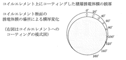
- the cross section of the monofilament used for observation was processed by polishing and CP (cross section polisher) after embedding the monofilament with resin. Specifically, as shown in FIG. 4, with respect to the substantially circular cross section, each position on the outer periphery was determined every 0 ° from 0 ° to 160 °, and the film thickness at each position was measured. Ten sections were sampled and measured at each angle of each section.
- a variable angle spectrophotometer that is, a UV-visible infrared spectrophotometer + automatic absolute reflectance measurement unit was used in combination (JASCO, V-670 + ARMN735).
- incident light was given to a sample (fastener element), while the detector was rotated to measure the difference in detection light (visible light wavelength range (specific wavelength)) depending on the angle.
- the incident light was 45 ° in any of the examples unless otherwise specified.
- the tangent is set at the upper part of the upper leg part as a reference (0 °).
- the obtained detection light (wavelength distribution) data (spectral distribution, tristimulus value) was converted into xyz chromaticity and further data of the CIE L * a * b * color system as necessary.
- Example 1 A film was formed so as to have the configuration described in Table 1 below. Then, using the above method, the difference in detected light depending on the observation angle was measured and converted into data of a value and b value of L * a * b * color system.
- Example 2 A film was formed so as to have the configuration described in Table 2 below.
- a fastener described in JP-A-2001-178508 was prepared.
- the difference of the detection light (red, green, blue) by an observation angle was measured using the said method.
- white light the intensity of light of each wavelength of the light source having all wavelengths in the visible light region is assumed to be 100%
- the ratio of the intensity of the reflected light to the incident light of each wavelength is detected.
- the obtained intensity (spectrum) of each wavelength was converted into a color.
- Example 3 A film was formed so as to have the configuration described in Table 3 below. And using the said method, incident light was 85 degrees and observation angle was 95 degrees, and the difference in the detected light by each wavelength was measured.
- the intensity of reflected light could be changed depending on the thickness of each layer and the number of layers.
- the number of layers is the same (six layers) and the film thickness is different, but a difference is seen in the intensity of reflected light.
- the interference pattern can be further diversified by changing the number of layers and the film thickness.
Landscapes
- Chemical & Material Sciences (AREA)
- Chemical Kinetics & Catalysis (AREA)
- Engineering & Computer Science (AREA)
- Materials Engineering (AREA)
- Mechanical Engineering (AREA)
- Metallurgy (AREA)
- Organic Chemistry (AREA)
- Slide Fasteners (AREA)
- Laminated Bodies (AREA)
Abstract
Description
(1) ファスナーテープに装着するためのコイル状のスライドファスナー用ファスナーエレメントであって、
前記ファスナーエレメントは、噛合頭部と、上脚部と、下脚部と、前記上脚部及び前記下脚部を連結する反転部とを備え、
少なくとも前記上脚部に少なくとも1つの光透過性の層を含む被膜が形成され、
前記光透過性の層の層厚は、前記上脚部の略頂上部から、前記ファスナーテープ側へ向かって漸次減少するように形成され、
前記略頂上部の層厚は、最大で約50~約1500nmである(場合により、樹脂の膜厚を除き(樹脂トップコートは含まず)最大で約50~約1500nmである)、
スライドファスナー用ファスナーエレメント。 To achieve the above object, the present invention provides a fastener element having the following characteristics:
(1) A coil-shaped fastener element for a slide fastener to be attached to a fastener tape,
The fastener element includes a meshing head, an upper leg, a lower leg, and an inversion part that connects the upper leg and the lower leg.
A coating including at least one light transmissive layer is formed on at least the upper leg;
The layer thickness of the light-transmitting layer is formed so as to gradually decrease from a substantially top portion of the upper leg portion toward the fastener tape side,
The thickness of the substantially top portion is about 50 to about 1500 nm at the maximum (in some cases, excluding the resin film thickness (not including the resin top coat), the maximum is about 50 to about 1500 nm),
Fastener element for slide fastener.
(5) the light-transmitting layer is a dielectric (e.g., TiO 2, Ta 2 O 5 , Nb 2 O 5,
図1は、一実施形態に係る本発明のファスナーエレメントを含めたスライドファスナー1全体の構成を表す。本発明の一実施形態に係るコイル状ファスナーエレメント2は、ファスナーテープ10に縫糸12によって縫着されている。ファスナーエレメント2は、噛合頭部6を備え、スライダー17の摺動により、1対の対向する噛合頭部同士が噛合する。 <1. Structure of fastener>
FIG. 1 shows a configuration of an
図2は、一実施形態に係る本発明のファスナーエレメントの構成を示す。ファスナーエレメント2は、モノフィラメント22をコイル状に捲回してコイル状ファスナーエレメント2を形成する。前記コイル状ファスナーエレメント2は、噛合頭部6、上脚部7、下脚部8、及び上脚部7と下脚部8とを連結する反転部9から構成される。ファスナーエレメントの材料は、特に限定されないが、例えば樹脂(PET等)を用いることができる。また、ファスナーエレメントの材料は、無色透明であってもよく、或いは着色されていてもよい。また、後述するように下地として金属層でコーティングしてもよい。 <2. Structure of fastener element>
FIG. 2 shows the configuration of the fastener element of the present invention according to one embodiment. The
一実施形態において、図2(24)及び図3に示すように、上脚部の断面図は略円形となっている。ここで、該断面の形状は、必ずしも円形、又は略円形である必要はなく、楕円や多角形(例えば、6角形、8角形、12角形等)等の形状であってもよい。 <3. Structure of the upper leg coating>
In one embodiment, as shown in FIG. 2 (24) and FIG. 3, the cross-sectional view of the upper leg portion is substantially circular. Here, the shape of the cross section is not necessarily circular or substantially circular, and may be an ellipse, a polygon (for example, a hexagon, an octagon, a dodecagon, or the like).
一実施形態において、被膜(光透過性の層)を形成する層として用いる材料は、任意の光透過性の材料を用いることができる。例えば、誘電体、導電性化合物、有色化合物、極薄(数nm~数十nm)の金属、半導体等が使用できる。典型的には、誘電体であるが、誘電体は、電気を通さない絶縁体としてふるまうため、光透過性を示すモノが多い。プラスチック、セラミック、雲母、油などが誘電体に相当するが、セラミックの誘電体としては、以下に例示されるものである:例えば、TiO2、Ta2O5、Nb2O5、ZrO2、HfO2、Sb2O3、CeO2、ZnO、AlN、La2O3、Gd2O3、Al2O3、SiO2、MgF2、MgO、Si3N4等(但し、材料は化学量論比でなくてもよい)。導電性化合物、有色化合物としては、以下に例示されるものである:ITO(In2O3:SnO2(5-10%))、SnO2、In2O3、TiN、Cr2O3、TiC、ZrC、NbC、TaC等(但し、材料は化学量論比でなくてもよい)。金属、半導体等としては、以下に例示されるものである:Ag、Al、Au、Cr、Cu、Fe、Ni、Ni-Cr、Ti、Zr、Mo、Pt、Pd、Si等。また、上記材料が酸化物、窒化物である場合には、その比率は整数比でなくても良く、任意の比率でよい。 <4. Coating Material>
In one embodiment, as a material used as a layer for forming a film (light transmissive layer), any light transmissive material can be used. For example, dielectrics, conductive compounds, colored compounds, ultrathin (several nm to several tens of nm) metals, semiconductors, and the like can be used. Typically, it is a dielectric, but since the dielectric behaves as an insulator that does not conduct electricity, many things exhibit light transmittance. Plastic, ceramic, mica, and the like oil is equivalent to the dielectric, as the ceramic dielectric are those illustrated below: For example, TiO 2, Ta 2 O 5 , Nb 2 O 5,
また、一実施形態において、光透過層として、高屈折材料と低屈折材料とを適宜使い分けることで、干渉模様に更なる多様性を与えることができる。例えば、表面光沢を強調する場合には高屈折材料を用いた層を表面に形成する。一方で、基材の色や干渉色を強調する場合には低屈折材料を用いた層を表面に形成する。高屈折材料としては、TiO2[屈折率: 2.2-2.5(測定波長:0.55μm)](以下、同様に記載する。)、Ta2O5[2-2.3(0.5μm)]、Nb2O5[2.1-2.3(0.5μm)]、ZrO2[2.05(0.5μm)]、HfO2[1.93 (0.55μm)]、Sb2O3[2.04(0.55μm)]、CeO2[2.0-2.4 (0.55μm)、ZnO[2(0.55μm)]、AlN[1.9-2.2(0.63μm)]、La2O3[1.95(0.55μm)]、Gd2O3[1.92(0.55μm)]、Si3N4[2.05(0.55μm)]等や前述の材料を含む各種混合材料などが挙げられるがこれらに限定されない。低屈折材料としては、Al2O3[1.63(0.55μm)]、SiO2[1.45-1.47(0.55μm)]、MgF2[1.38(0.55μm)]、MgO[1.7(0.5μm)]等や前述の材料を含む各種混合材料などが挙げられるがこれらに限定されない。また、屈折率で特定するならば、高屈折材料の層の屈折率は、典型的には1.9~2.5であり、低屈折材料の層の屈折率は、典型的には1.38~1.72である。 <5. Refractive index of material>
Further, in one embodiment, the interference pattern can be further diversified by appropriately using a high refractive material and a low refractive material as the light transmission layer. For example, when emphasizing surface gloss, a layer using a high refractive material is formed on the surface. On the other hand, when emphasizing the color or interference color of the substrate, a layer using a low refractive material is formed on the surface. Examples of the highly refractive material include TiO 2 [refractive index: 2.2-2.5 (measurement wavelength: 0.55 μm)] (hereinafter the same), Ta 2 O 5 [2-2.3 (0 0.5 μm)], Nb 2 O 5 [2.1-2.3 (0.5 μm)], ZrO 2 [2.05 (0.5 μm)], HfO 2 [1.93 (0.55 μm)], Sb 2 O 3 [2.04 (0.55 μm)], CeO 2 [2.0-2.4 (0.55 μm), ZnO [2 (0.55 μm)], AlN [1.9-2.2 (0.63 μm)], La 2 O 3 [1.95 (0.55 μm)], Gd 2 O 3 [1.92 (0.55 μm)], Si 3 N 4 [2.05 (0.55 μm)] ] And various mixed materials including the above-mentioned materials, but are not limited thereto. Examples of the low refractive material include Al 2 O 3 [1.63 (0.55 μm)], SiO 2 [1.45-1.47 (0.55 μm)], MgF 2 [1.38 (0.55 μm)]. , MgO [1.7 (0.5 μm)], and various mixed materials including the above-mentioned materials, but are not limited thereto. If specified by the refractive index, the refractive index of the layer of the high refractive material is typically 1.9 to 2.5, and the refractive index of the layer of the low refractive material is typically 1. 38 to 1.72.
一実施形態において、前記被膜は、少なくとも1つの光透過性の層が有色層であってもよい。典型的には、前記被膜が複数の層を含む場合に、層と層の間に存在する少なくとも1つの光透過性の層が有色層であってもよい。あるいは、典型的には、任意の層とモノフィラメントとの間に存在する少なくとも1つの光透過性の層が有色層であってもよい。なお「有色」とは、白色以外の色で着色されていることを意味する。前記有色層の材料としては、例えば、有色化合物や金属が挙げられる。これらを材料とする膜を設けることで、特定の色調を強調することができる。これらを材料とする膜は、光が透過するレベルの薄いレベルであることが好ましい。典型的な厚さは、最大膜厚が約100nm以下、好ましくは約5~約50nmである。有色化合物としては、例えば、TiN、Cr2O3、TiC、ZrC、NbC、TaC等が挙げられる。前記金属材料としては、Au、Cu、Ag、Ni、Cr、Ti、Zr、Nb、Ta、Sn、Si等が挙げられる。 <6. Other layer structures>
In one embodiment, in the coating film, at least one light-transmitting layer may be a colored layer. Typically, when the coating includes a plurality of layers, at least one light-transmitting layer present between the layers may be a colored layer. Alternatively, typically, at least one light-transmitting layer present between any layer and the monofilament may be a colored layer. “Colored” means that it is colored with a color other than white. Examples of the material for the colored layer include colored compounds and metals. By providing a film made of these materials, a specific color tone can be emphasized. The film made of these materials is preferably a thin level that allows light to pass through. A typical thickness is a maximum film thickness of about 100 nm or less, preferably about 5 to about 50 nm. Examples of the colored compound include TiN, Cr 2 O 3 , TiC, ZrC, NbC, TaC, and the like. Examples of the metal material include Au, Cu, Ag, Ni, Cr, Ti, Zr, Nb, Ta, Sn, and Si.
合成樹脂(例えば、PET、POM等)のモノフィラメントをコイル状に捲回してコイル状ファスナーエレメントを材料として用いることができる。ファスナーエレメント上脚部の露出部分に対して、被膜を形成する作業を行う。被膜形成後に、ファスナーエレメントはファスナーテープに縫着され、スライドファスナーとなる。また、一方で、ファスナーエレメントをファスナーテープに縫着した後、ファスナーエレメントの上脚部以外をマスキングして被膜を形成することもできる。被膜を形成するためには、真空蒸着、イオンプレーティング、スパッタリング、化学蒸着等の所望の乾式めっき手段を用いることができる。典型的にはスパッタリングを用いて被膜を形成する。誘電体層のみならず、他の層である有色化合物層、金属膜や硬質膜のトップコートを形成する場合については、乾式めっきの手法(スパッタリングや蒸着、イオンプレーティング等)で成膜することができ、軟質の樹脂トップコートは、乾式めっきの手法ではなく、従来のスプレーやディッピングで成膜することができる。 <7. Manufacturing method>
A coil-shaped fastener element can be used as a material by winding a monofilament of synthetic resin (for example, PET, POM, etc.) into a coil shape. The film is formed on the exposed portion of the upper leg portion of the fastener element. After the coating is formed, the fastener element is sewn to the fastener tape to form a slide fastener. On the other hand, after the fastener element is sewn to the fastener tape, the film other than the upper leg portion of the fastener element can be masked to form a film. In order to form the film, a desired dry plating means such as vacuum deposition, ion plating, sputtering, chemical vapor deposition or the like can be used. Typically, the coating is formed using sputtering. When forming not only the dielectric layer but also the colored compound layer, which is another layer, or the top coat of a metal film or hard film, the film should be formed by a dry plating method (sputtering, vapor deposition, ion plating, etc.). The soft resin topcoat can be formed by conventional spraying or dipping, not by dry plating.
後述する表に記載した材料のターゲットを用意した。ターゲットサイズは10インチ×3インチとした。場合によっては、異なる材料を持つ層を交互に形成するために、デュアルターゲットを用いて被膜のコーティングを行った。 <1. Manufacturing method>
The target of the material described in the table | surface mentioned later was prepared. The target size was 10 inches × 3 inches. In some cases, a dual target was used to coat the film in order to alternately form layers with different materials.
被膜の膜厚については、モノフィラメントの断面をFE-SEM(日立製 S-4800)で観察することによって測定した。観察に用いるモノフィラメントの断面は、モノフィラメントを樹脂埋し、研磨およびCP(クロスセクションポリッシャー)にて処理を行った。具体的には、図4に記載するように、略円形の断面について、外周の各位置を0°~160°まで20°ごとに定め、それぞれの位置での膜厚を測定した。断面を10箇所サンプリングして、各断面の各角度ごとに測定した。 <2. Measuring method of film thickness>
The film thickness of the coating was measured by observing the cross section of the monofilament with FE-SEM (Hitachi S-4800). The cross section of the monofilament used for observation was processed by polishing and CP (cross section polisher) after embedding the monofilament with resin. Specifically, as shown in FIG. 4, with respect to the substantially circular cross section, each position on the outer periphery was determined every 0 ° from 0 ° to 160 °, and the film thickness at each position was measured. Ten sections were sampled and measured at each angle of each section.
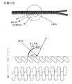
観察角度による色調変化を調べるために、角度可変分光光度計、即ち、紫外可視赤外分光光度計+自動絶対反射率測定ユニットを組み合せて(日本分光、V-670+ARMN735)用いた。図5に示すように、入射光を試料(ファスナーエレメント)に与え、一方で検出器を回転させることにより、角度による検出光(可視光波長全域(特定波長))の違いを測定した。入射光については、特に記載しないかぎり、いずれの実施例でも45°とした。図5下側に表すように、入射光の角度及び観察角度(検出部の位置)については、コイルエレメントを側面から見たときに、上脚部の上部に接線を基準(0°)にして定義した。得られた検出光(波長分布)データ(分光分布、3刺激値)は、必要に応じて、xyz色度、さらにはCIEL*a*b*表色系のデータに変換した。 <3. Measuring method of color change>
In order to examine the color tone change depending on the observation angle, a variable angle spectrophotometer, that is, a UV-visible infrared spectrophotometer + automatic absolute reflectance measurement unit was used in combination (JASCO, V-670 + ARMN735). As shown in FIG. 5, incident light was given to a sample (fastener element), while the detector was rotated to measure the difference in detection light (visible light wavelength range (specific wavelength)) depending on the angle. The incident light was 45 ° in any of the examples unless otherwise specified. As shown in the lower side of FIG. 5, with respect to the angle of incident light and the observation angle (the position of the detection unit), when the coil element is viewed from the side, the tangent is set at the upper part of the upper leg part as a reference (0 °). Defined. The obtained detection light (wavelength distribution) data (spectral distribution, tristimulus value) was converted into xyz chromaticity and further data of the CIE L * a * b * color system as necessary.
以下表1に記載する構成となるように、被膜を形成した。そして、上記方法を用いて、観察角度による検出光の違いを測定し、L*a*b*表色系のa値及びb値のデータに変換した。 <Example 1>
A film was formed so as to have the configuration described in Table 1 below. Then, using the above method, the difference in detected light depending on the observation angle was measured and converted into data of a value and b value of L * a * b * color system.

以下表2に記載する構成となるように、被膜を形成した。また、比較材料として、特開2001-178508号公報に記載のファスナーを用意した。そして、上記方法を用いて、観察角度による検出光(赤、緑、青)の違いを測定した。具体的には、白色光(可視光域全波長を持つ光源の各波長の光の強度を100%とする。)を入射し、反射した光の各波長の入射光に対する強度の割合を検出した。得られた各波長の強度(スペクトル)を色に換算した。 <Example 2>
A film was formed so as to have the configuration described in Table 2 below. As a comparative material, a fastener described in JP-A-2001-178508 was prepared. And the difference of the detection light (red, green, blue) by an observation angle was measured using the said method. Specifically, white light (the intensity of light of each wavelength of the light source having all wavelengths in the visible light region is assumed to be 100%) is incident, and the ratio of the intensity of the reflected light to the incident light of each wavelength is detected. . The obtained intensity (spectrum) of each wavelength was converted into a color.

以下表3に記載する構成となるように、被膜を形成した。そして、上記方法を用いて、入射光を85°及び観察角度を95°にして、各波長による検出光の違いを測定した。 <Example 3>
A film was formed so as to have the configuration described in Table 3 below. And using the said method, incident light was 85 degrees and observation angle was 95 degrees, and the difference in the detected light by each wavelength was measured.


以下の表に記載された膜の構成となるように、2種類の膜厚(約500nm、及び約1.5μm超)をもつファスナーエレメントを調製した。両方の試料に対して、コイルエレメントを10回折り曲げた(180°から-180°で屈曲させた)のち、セロファンテープを貼り付け、しごいて、剥がしたあとで、被膜の割れ、剥離具合を比較した。図9に丸線で記載されているように最大膜厚が約1.5μmを越えるコイルエレメントの場合には、割れて剥離し、膜がなくなっていた。 <Example 4>
Fastener elements having two different film thicknesses (about 500 nm and greater than about 1.5 μm) were prepared so as to have the membrane configurations described in the table below. For both samples, the coil element was bent 10 times (bent from 180 ° to -180 °), and then the cellophane tape was applied, squeezed and peeled off, and then the film cracked and peeled. Compared. In the case of a coil element having a maximum film thickness exceeding about 1.5 μm as indicated by a round line in FIG. 9, the film was cracked and peeled off, and the film disappeared.


2 (コイル状)ファスナーエレメント
6 噛合頭部
7 上脚部
8 下脚部
9 反転部
10 ファスナーテープ
11 芯紐
12 縫糸
17 スライダー
18 ガイド柱
19 ガイドフランジ
20 被膜
22 モノフィラメント
24 上脚部断面 DESCRIPTION OF
Claims (12)
- ファスナーテープ10に装着するためのコイル状のスライドファスナー用ファスナーエレメントであって、
前記ファスナーエレメントは、噛合頭部6と、上脚部7と、下脚部8と、前記上脚部7及び前記下脚部8を連結する反転部9とを備え
少なくとも前記上脚部7に少なくとも1つの光透過性の層を含む被膜20が形成され、
前記光透過性の層の層厚は、前記上脚部7の略頂上部から、前記ファスナーテープ10側へ向かって漸次減少するように形成され、
前記略頂上部の層厚は、最大で約50~約1500nmである
スライドファスナー用ファスナーエレメント。 A coil-shaped fastener element for a slide fastener to be attached to the fastener tape 10,
The fastener element includes a meshing head 6, an upper leg portion 7, a lower leg portion 8, and an inversion portion 9 that connects the upper leg portion 7 and the lower leg portion 8. A coating 20 comprising two light transmissive layers is formed;
The layer thickness of the light transmissive layer is formed so as to gradually decrease from substantially the top of the upper leg portion 7 toward the fastener tape 10 side,
A fastener element for a slide fastener, wherein the layer thickness of the substantially top portion is about 50 to about 1500 nm at the maximum. - 前記光透過性の層の縁が、前記上脚部7の断面水平方向の中心線を、前記ファスナーテープ10側へ超えて形成される請求項1に記載のスライドファスナー用ファスナーエレメント。 2. The fastener element for a slide fastener according to claim 1, wherein an edge of the light transmissive layer is formed to extend to a side of the fastener tape 10 from a horizontal center line of the upper leg portion 7.
- 前記光透過性の層が、積層した少なくとも2種の光透過性の層を含み、前記少なくとも2種の光透過性の層によって形成される少なくとも1つの界面で光が反射される請求項1又は2に記載のスライドファスナー用ファスナーエレメント。 The light transmissive layer includes at least two kinds of light transmissive layers stacked, and light is reflected at at least one interface formed by the at least two kinds of light transmissive layers. The fastener element for slide fasteners of 2.
- 前記光透過性の層が、光透過性の層を3つ以上積層して形成され、隣接する2つの層の相対的な屈折率が交互に高/低となるように積層して形成される請求項1~3のいずれか1項に記載のスライドファスナー用ファスナーエレメント。 The light-transmitting layer is formed by stacking three or more light-transmitting layers, and is stacked so that the relative refractive index of two adjacent layers alternately becomes high / low. The fastener element for a slide fastener according to any one of claims 1 to 3.
- 前記光透過性の層が誘電体を材料として含む請求項1~4のいずれか1項に記載のスライドファスナー用ファスナーエレメント。 The slide fastener fastener element according to any one of claims 1 to 4, wherein the light transmissive layer includes a dielectric as a material.
- 前記光透過性の層が導電性化合物、有色化合物または金属・半導体を材料として含む請求項1~5のいずれか1項に記載のスライドファスナー用ファスナーエレメント。 The slide fastener fastener element according to any one of claims 1 to 5, wherein the light transmissive layer includes a conductive compound, a colored compound, or a metal / semiconductor.
- 前記導電性化合物、有色化合物または金属・半導体を材料として含む層の層厚が100nm以下である請求項6に記載のスライドファスナー用ファスナーエレメント。 The fastener element for a slide fastener according to claim 6, wherein a layer thickness of the layer containing the conductive compound, the colored compound or the metal / semiconductor as a material is 100 nm or less.
- 前記光透過性の層の外側に樹脂を材料として含む層が形成されている請求項1~7のいずれか1項に記載のスライドファスナー用ファスナーエレメント。 The slide fastener fastener element according to any one of claims 1 to 7, wherein a layer containing a resin as a material is formed outside the light transmissive layer.
- 樹脂を材料として含む前記層の最大膜厚が500nm以上である請求項8に記載のスライドファスナー用ファスナーエレメント。 The fastener element for a slide fastener according to claim 8, wherein the maximum film thickness of the layer containing resin as a material is 500 nm or more.
- 金属を材料として含む層が、前記被膜20と前記上脚部7との間に形成された請求項1~9のいずれか1項に記載のスライドファスナー用ファスナーエレメント。 The slide fastener fastener element according to any one of claims 1 to 9, wherein a layer containing a metal as a material is formed between the coating 20 and the upper leg portion 7.
- 金属を材料として含む前記層の最大層厚が100nm以下である請求項10に記載のスライドファスナー用ファスナーエレメント。 The fastener element for a slide fastener according to claim 10, wherein the maximum layer thickness of the layer containing metal as a material is 100 nm or less.
- 請求項1~11のいずれか1項に記載のファスナーエレメントを備えるスライドファスナー。 A slide fastener comprising the fastener element according to any one of claims 1 to 11.
Priority Applications (7)
| Application Number | Priority Date | Filing Date | Title |
|---|---|---|---|
| PCT/JP2012/068712 WO2014016908A1 (en) | 2012-07-24 | 2012-07-24 | Fastener element for slide fastener |
| JP2014526644A JP5973573B2 (en) | 2012-07-24 | 2012-07-24 | Fastener element for slide fastener |
| DE112012006726.6T DE112012006726B4 (en) | 2012-07-24 | 2012-07-24 | Dome element for zippers |
| US14/415,787 US9528178B2 (en) | 2012-07-24 | 2012-07-24 | Fastener element for slide fasteners |
| TW102126359A TWI486136B (en) | 2012-07-24 | 2013-07-23 | Zipper |
| CN201310314723.4A CN103564994B (en) | 2012-07-24 | 2013-07-24 | Slide fastener sprocket |
| CN201320444772.5U CN203538527U (en) | 2012-07-24 | 2013-07-24 | Zipper tooth |
Applications Claiming Priority (1)
| Application Number | Priority Date | Filing Date | Title |
|---|---|---|---|
| PCT/JP2012/068712 WO2014016908A1 (en) | 2012-07-24 | 2012-07-24 | Fastener element for slide fastener |
Publications (1)
| Publication Number | Publication Date |
|---|---|
| WO2014016908A1 true WO2014016908A1 (en) | 2014-01-30 |
Family
ID=49996744
Family Applications (1)
| Application Number | Title | Priority Date | Filing Date |
|---|---|---|---|
| PCT/JP2012/068712 WO2014016908A1 (en) | 2012-07-24 | 2012-07-24 | Fastener element for slide fastener |
Country Status (6)
| Country | Link |
|---|---|
| US (1) | US9528178B2 (en) |
| JP (1) | JP5973573B2 (en) |
| CN (2) | CN203538527U (en) |
| DE (1) | DE112012006726B4 (en) |
| TW (1) | TWI486136B (en) |
| WO (1) | WO2014016908A1 (en) |
Cited By (2)
| Publication number | Priority date | Publication date | Assignee | Title |
|---|---|---|---|---|
| WO2017122745A1 (en) * | 2016-01-15 | 2017-07-20 | Ykk株式会社 | Ceramic component, fastener stringer containing same, and method for producing fastener stringer |
| US11043884B2 (en) | 2018-08-28 | 2021-06-22 | Pratt & Whitney Canada Corp. | Multi-rotor electric machine |
Families Citing this family (6)
| Publication number | Priority date | Publication date | Assignee | Title |
|---|---|---|---|---|
| US9521883B2 (en) * | 2012-05-28 | 2016-12-20 | Ykk Corporation | Slide fastener |
| WO2014016908A1 (en) * | 2012-07-24 | 2014-01-30 | Ykk株式会社 | Fastener element for slide fastener |
| CN105133075B (en) * | 2015-10-14 | 2017-09-22 | 浙江伟星实业发展股份有限公司 | A kind of teeth of slide fastener |
| CN107280152B (en) * | 2016-03-31 | 2021-04-27 | 吉田拉链(深圳)有限公司 | Method for manufacturing slide fastener and slide fastener |
| CN106343666A (en) * | 2016-08-25 | 2017-01-25 | 深圳市联星服装辅料有限公司 | Method of zipper processed by plastic steel pad pasting laser |
| CN109280200B (en) * | 2017-07-19 | 2022-04-08 | Ykk株式会社 | Method for forming rubber layer on surface of resin material, and zipper, buckle and snap fastener using the same |
Citations (4)
| Publication number | Priority date | Publication date | Assignee | Title |
|---|---|---|---|---|
| JPH01160502A (en) * | 1987-12-18 | 1989-06-23 | Yoshida Kogyo Kk <Ykk> | Metal element for slide fastener |
| JPH043012U (en) * | 1990-04-20 | 1992-01-13 | ||
| JPH11155615A (en) * | 1997-12-02 | 1999-06-15 | Ykk Corp | Retroreflective filament slide fastener |
| JP2001178508A (en) * | 1999-12-27 | 2001-07-03 | Ykk Corp | Fastener element for slide fastener |
Family Cites Families (16)
| Publication number | Priority date | Publication date | Assignee | Title |
|---|---|---|---|---|
| DE2150999A1 (en) * | 1971-10-13 | 1973-04-19 | Opti Holding Ag | ZIPPER |
| US4456663A (en) * | 1981-12-02 | 1984-06-26 | United States Steel Corporation | Hot-dip aluminum-zinc coating method and product |
| JPS6137960A (en) * | 1984-07-28 | 1986-02-22 | Tadanobu Okubo | Metal surface processing method |
| JPS6420805A (en) * | 1987-07-14 | 1989-01-24 | Yoshida Kogyo Kk | Slide fastener |
| CA2011944C (en) * | 1989-03-16 | 1996-02-20 | Yoshiyuki Horita | Slide fastener and fastener elements therefor |
| JP2908511B2 (en) | 1990-04-20 | 1999-06-21 | 日本電信電話株式会社 | Driving method of semiconductor optical device |
| JP3260995B2 (en) * | 1994-12-28 | 2002-02-25 | ワイケイケイ株式会社 | Luminescent synthetic resin material, method for producing the same, and molded article |
| DE19746067A1 (en) * | 1997-10-17 | 1999-04-22 | Merck Patent Gmbh | Interference pigments based on flaky substrates used in paint, lacquer, printing ink, plastics, ceramics, glaze and cosmetics |
| DE19915153A1 (en) * | 1999-02-15 | 2000-08-17 | Merck Patent Gmbh | Color interference pigments |
| JP3430062B2 (en) * | 1999-02-26 | 2003-07-28 | 日産自動車株式会社 | Coloring structure |
| JP2001003125A (en) * | 1999-06-17 | 2001-01-09 | Ykk Corp | Nickel-free white copper alloy material |
| CN1922267B (en) * | 2004-03-22 | 2012-03-28 | 捷时雅股份有限公司 | Curable liquid resin composition and method for producing multilayer body using same |
| US20080000064A1 (en) * | 2006-06-28 | 2008-01-03 | Ching Song Chou | Method of Manufacturing Color Metal Zipper and Apparatus Therefor |
| US8434909B2 (en) * | 2007-10-09 | 2013-05-07 | Flex Lighting Ii, Llc | Light emitting display with light mixing within a film |
| JP5697739B2 (en) * | 2011-02-21 | 2015-04-08 | 積水化成品工業株式会社 | Light reflector |
| WO2014016908A1 (en) * | 2012-07-24 | 2014-01-30 | Ykk株式会社 | Fastener element for slide fastener |
-
2012
- 2012-07-24 WO PCT/JP2012/068712 patent/WO2014016908A1/en active Application Filing
- 2012-07-24 US US14/415,787 patent/US9528178B2/en active Active
- 2012-07-24 JP JP2014526644A patent/JP5973573B2/en active Active
- 2012-07-24 DE DE112012006726.6T patent/DE112012006726B4/en active Active
-
2013
- 2013-07-23 TW TW102126359A patent/TWI486136B/en active
- 2013-07-24 CN CN201320444772.5U patent/CN203538527U/en not_active Withdrawn - After Issue
- 2013-07-24 CN CN201310314723.4A patent/CN103564994B/en active Active
Patent Citations (4)
| Publication number | Priority date | Publication date | Assignee | Title |
|---|---|---|---|---|
| JPH01160502A (en) * | 1987-12-18 | 1989-06-23 | Yoshida Kogyo Kk <Ykk> | Metal element for slide fastener |
| JPH043012U (en) * | 1990-04-20 | 1992-01-13 | ||
| JPH11155615A (en) * | 1997-12-02 | 1999-06-15 | Ykk Corp | Retroreflective filament slide fastener |
| JP2001178508A (en) * | 1999-12-27 | 2001-07-03 | Ykk Corp | Fastener element for slide fastener |
Cited By (5)
| Publication number | Priority date | Publication date | Assignee | Title |
|---|---|---|---|---|
| WO2017122745A1 (en) * | 2016-01-15 | 2017-07-20 | Ykk株式会社 | Ceramic component, fastener stringer containing same, and method for producing fastener stringer |
| JP2017124121A (en) * | 2016-01-15 | 2017-07-20 | Ykk株式会社 | Ceramic component and fastener stringer including the same, and method for manufacturing fastener stringer |
| US11043884B2 (en) | 2018-08-28 | 2021-06-22 | Pratt & Whitney Canada Corp. | Multi-rotor electric machine |
| US11569718B2 (en) | 2018-08-28 | 2023-01-31 | Pratt & Whitney Canada Corp. | Multi-rotor electric machine |
| US11843293B2 (en) | 2018-08-28 | 2023-12-12 | Pratt & Whitney Canada Corp. | Multi-rotor electric machine |
Also Published As
| Publication number | Publication date |
|---|---|
| US20150184277A1 (en) | 2015-07-02 |
| TW201406318A (en) | 2014-02-16 |
| CN203538527U (en) | 2014-04-16 |
| JP5973573B2 (en) | 2016-08-23 |
| US9528178B2 (en) | 2016-12-27 |
| JPWO2014016908A1 (en) | 2016-07-07 |
| DE112012006726B4 (en) | 2019-05-29 |
| CN103564994A (en) | 2014-02-12 |
| CN103564994B (en) | 2017-08-15 |
| DE112012006726T5 (en) | 2015-06-11 |
| TWI486136B (en) | 2015-06-01 |
Similar Documents
| Publication | Publication Date | Title |
|---|---|---|
| JP5973573B2 (en) | Fastener element for slide fastener | |
| US9482798B2 (en) | Plasmonic nano-color coating layer and method for fabricating the same | |
| CN110749945B (en) | Optical film, structural color pigment and preparation method of optical film | |
| JP4998016B2 (en) | Glass top plate for cooker | |
| JP2009078458A (en) | Apparatus housing and apparatus decoration with interference color film | |
| JP3430094B2 (en) | Paint structure | |
| JP7297031B2 (en) | Methods for depositing coatings on items such as clockwork components, and items coated by such methods | |
| JP2014237819A (en) | High-chroma omnidirectional structural color multi-layer structure | |
| JP2016049777A (en) | Red omnidirectional structural color made by metal and dielectric layers | |
| JP7051885B2 (en) | Interfering pigment | |
| CN107422402A (en) | A kind of damage resistant hyaline membrane and preparation method thereof | |
| CN110703377A (en) | Red optical color-changing sheet and preparation method thereof | |
| CN103264549B (en) | The front infrared shield glass consistent with offside reflection tone | |
| KR102215030B1 (en) | Metal member with colored surface and coloring method of metal surface | |
| CN110806613B (en) | Red optical color-changing sheet capable of enhancing color change and preparation method thereof | |
| JP7540637B2 (en) | Film-coated transparent substrate and top plate for cooking appliance | |
| JPH0437805A (en) | Reflecting mirror consisting of laminated thin film | |
| JP7232362B2 (en) | Outer part for timepieces or jewellery, coated with interference color, and method of making same | |
| CN211348689U (en) | Red optical color-changing sheet capable of enhancing color change | |
| CN211348690U (en) | Red optical color-changing sheet | |
| KR20190120829A (en) | Colored laminated glass | |
| JP5622953B1 (en) | Ceramic products | |
| JP2004058273A (en) | Clear coating-applied metallic sheet with stable color tone | |
| JP2000027018A (en) | False eyelashes | |
| CN117706670A (en) | All-dielectric metal bright silver structural color film and preparation method thereof |
Legal Events
| Date | Code | Title | Description |
|---|---|---|---|
| 121 | Ep: the epo has been informed by wipo that ep was designated in this application |
Ref document number: 12881625 Country of ref document: EP Kind code of ref document: A1 |
|
| ENP | Entry into the national phase |
Ref document number: 2014526644 Country of ref document: JP Kind code of ref document: A |
|
| WWE | Wipo information: entry into national phase |
Ref document number: 14415787 Country of ref document: US |
|
| WWE | Wipo information: entry into national phase |
Ref document number: 1120120067266 Country of ref document: DE Ref document number: 112012006726 Country of ref document: DE |
|
| 122 | Ep: pct application non-entry in european phase |
Ref document number: 12881625 Country of ref document: EP Kind code of ref document: A1 |