WO2014014031A1 - 被写体追尾装置およびカメラ - Google Patents
被写体追尾装置およびカメラ Download PDFInfo
- Publication number
- WO2014014031A1 WO2014014031A1 PCT/JP2013/069427 JP2013069427W WO2014014031A1 WO 2014014031 A1 WO2014014031 A1 WO 2014014031A1 JP 2013069427 W JP2013069427 W JP 2013069427W WO 2014014031 A1 WO2014014031 A1 WO 2014014031A1
- Authority
- WO
- WIPO (PCT)
- Prior art keywords
- image
- size
- template image
- template
- subject
- Prior art date
- Legal status (The legal status is an assumption and is not a legal conclusion. Google has not performed a legal analysis and makes no representation as to the accuracy of the status listed.)
- Ceased
Links
Images


Classifications
-
- G—PHYSICS
- G06—COMPUTING OR CALCULATING; COUNTING
- G06T—IMAGE DATA PROCESSING OR GENERATION, IN GENERAL
- G06T7/00—Image analysis
- G06T7/20—Analysis of motion
- G06T7/246—Analysis of motion using feature-based methods, e.g. the tracking of corners or segments
- G06T7/248—Analysis of motion using feature-based methods, e.g. the tracking of corners or segments involving reference images or patches
-
- G—PHYSICS
- G06—COMPUTING OR CALCULATING; COUNTING
- G06F—ELECTRIC DIGITAL DATA PROCESSING
- G06F18/00—Pattern recognition
- G06F18/20—Analysing
- G06F18/22—Matching criteria, e.g. proximity measures
-
- G—PHYSICS
- G06—COMPUTING OR CALCULATING; COUNTING
- G06T—IMAGE DATA PROCESSING OR GENERATION, IN GENERAL
- G06T3/00—Geometric image transformations in the plane of the image
- G06T3/40—Scaling of whole images or parts thereof, e.g. expanding or contracting
-
- G—PHYSICS
- G06—COMPUTING OR CALCULATING; COUNTING
- G06V—IMAGE OR VIDEO RECOGNITION OR UNDERSTANDING
- G06V10/00—Arrangements for image or video recognition or understanding
- G06V10/20—Image preprocessing
- G06V10/24—Aligning, centring, orientation detection or correction of the image
-
- G—PHYSICS
- G06—COMPUTING OR CALCULATING; COUNTING
- G06V—IMAGE OR VIDEO RECOGNITION OR UNDERSTANDING
- G06V10/00—Arrangements for image or video recognition or understanding
- G06V10/70—Arrangements for image or video recognition or understanding using pattern recognition or machine learning
- G06V10/74—Image or video pattern matching; Proximity measures in feature spaces
- G06V10/75—Organisation of the matching processes, e.g. simultaneous or sequential comparisons of image or video features; Coarse-fine approaches, e.g. multi-scale approaches; using context analysis; Selection of dictionaries
- G06V10/751—Comparing pixel values or logical combinations thereof, or feature values having positional relevance, e.g. template matching
-
- G—PHYSICS
- G06—COMPUTING OR CALCULATING; COUNTING
- G06T—IMAGE DATA PROCESSING OR GENERATION, IN GENERAL
- G06T2207/00—Indexing scheme for image analysis or image enhancement
- G06T2207/10—Image acquisition modality
- G06T2207/10004—Still image; Photographic image
-
- G—PHYSICS
- G06—COMPUTING OR CALCULATING; COUNTING
- G06T—IMAGE DATA PROCESSING OR GENERATION, IN GENERAL
- G06T2207/00—Indexing scheme for image analysis or image enhancement
- G06T2207/20—Special algorithmic details
- G06T2207/20004—Adaptive image processing
- G06T2207/20012—Locally adaptive
-
- G—PHYSICS
- G06—COMPUTING OR CALCULATING; COUNTING
- G06T—IMAGE DATA PROCESSING OR GENERATION, IN GENERAL
- G06T2207/00—Indexing scheme for image analysis or image enhancement
- G06T2207/20—Special algorithmic details
- G06T2207/20081—Training; Learning
-
- G—PHYSICS
- G06—COMPUTING OR CALCULATING; COUNTING
- G06T—IMAGE DATA PROCESSING OR GENERATION, IN GENERAL
- G06T2207/00—Indexing scheme for image analysis or image enhancement
- G06T2207/30—Subject of image; Context of image processing
- G06T2207/30196—Human being; Person
Definitions
- the present invention relates to a subject tracking device and a camera.
- This object tracking apparatus performs template matching using a plurality of different template images and updates the template image using the template image having the highest degree of similarity in order to respond to changes in the subject (see Patent Document 1). .
- the subject tracking device includes a search area setting unit that sets a search area in the input image, and a first degree that calculates the similarity between the tracking template image and the image in the search area. Based on the similarity calculated by the similarity calculation unit, the first similarity calculation unit, a subject position specifying unit for specifying the tracking subject position in the input image, and a plurality of sheets generated based on the tracking template image A second similarity calculation unit that calculates the similarity between the resizing determination template image and the image in the search region, and a plurality of similarity in the input image based on the similarity calculated by the second similarity calculation unit.
- the size changing unit is configured to change the tracking template when the density of the plurality of matching positions specified by the matching position specifying unit changes by a predetermined value or more. It is preferable to change the image size of the image and the resize determination template image.
- the size changing unit changes the image size when the density of the plurality of matching positions specified by the matching position specifying unit changes to a higher one. It is preferable to increase the image size when the density of the plurality of matching positions specified by the matching position specifying unit changes to a lower value.
- the size changing unit performs the second similarity calculation among the plurality of matching positions specified by the matching position specifying unit. It is preferable to select a matching position where the similarity calculated by the unit is higher than a predetermined level, and change the image size based on the density of the selected matching position.
- the plurality of resize determination template images may be images each including a different part of the tracking template image.
- the plurality of resize determination template images are respectively the center positions of the blocks in the tracking template image divided into a plurality of blocks. It is preferable that the image has a predetermined size centering on.
- the size changing unit uses the matching position for the resize determination template image centered on the center position of the middle block in the plurality of blocks.
- the size changing unit includes the resize determination template image centered on the center position of the middle block in the plurality of blocks and the image in the search region. It is preferable to determine whether or not to change the image size of the tracking template image and the resizing determination template image when the maximum similarity is a predetermined height or more.
- the subject tracking device includes a search region setting unit that sets a search region in the input image, the similarity between the initial template image and the image in the search region, and the combined template image and the search.
- a first similarity calculation unit that calculates the similarity to the image in the region, and a subject position that specifies a tracking subject position in the input image based on the similarity calculated by the first similarity calculation unit
- the determination unit determines whether to update the composite template image based on the specific unit and the similarity calculated by the first similarity calculation unit
- the update determination unit determines to update the composite template image
- the update unit updates an image obtained by combining the image including the tracking subject position in the input image and the initial template image as a new combined template image, and a plurality of resize images.
- a second similarity calculator that calculates the similarity between the template image and the image in the search area, and a plurality of resizings in the input image based on the similarity calculated by the second similarity calculator Based on the sparseness of the plurality of matching positions specified by the matching position specifying unit, the matching position specifying unit that specifies the matching position of the determination template image, and the initial template image, the combined template image, and the resizing determination template image
- a size change determination unit that determines whether or not to change the image size, and a size change unit that changes the image size of the initial template image to a new image size when the size change determination unit determines to change the image size.
- the update unit determines that the size change determination unit changes the image size, An image having a new image size including the tracking subject position in the force image is updated as a new combined template image, and the updated combined template image is divided into a plurality of blocks, and a new image including each block in the input image The size image is updated as a new resize determination template image.
- the subject tracking device includes: tracking means for tracking a specific subject in the image based on the template image; detection means for detecting a change in the size of the specific subject; Update means for updating the template image when it is detected that the size of the specific subject has changed by a predetermined amount or more.
- a camera includes the subject tracking device according to any one of the first to tenth aspects.
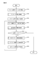
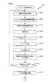
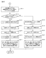
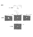
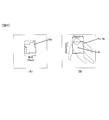
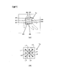
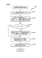
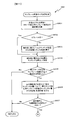
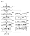
- FIG. 1 It is a block diagram explaining the structural example of the camera by one embodiment of this invention. It is a flowchart which shows the flow of a subject tracking process. It is a flowchart which shows the detail of a template image generation process. It is a flowchart following FIG. It is a figure explaining a binary image and an AND image. It is a figure explaining the production
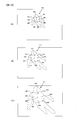
- FIG. 1 It is a flowchart which shows the detail of a template size update process. It is a flowchart following FIG. It is a figure explaining the relationship between the matching position about the resize determination template image and the size of the subject. It is a figure explaining the production
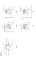
- FIG. 1 It is a flowchart which shows the detail of a template size update process. It is a flowchart following FIG. It is a figure explaining the relationship between the matching position about the resize determination template image and the size of the subject. It is a figure explaining the production
- FIG. 1 is a block diagram illustrating a configuration of an embodiment of a camera according to the present embodiment.
- the camera 100 includes an operation member 101, a lens 102, an image sensor 103, a control device 104, a memory card slot 105, and a monitor 106.
- the operation member 101 includes various input members operated by the user, such as a power button, a release button, a zoom button, a cross key, an enter button, a play button, and a delete button.
- the lens 102 is composed of a plurality of optical lenses, but is representatively represented by one lens in FIG.
- the image sensor 103 is an image sensor such as a CMOS, and captures a subject image formed by the lens 102. Then, an image signal obtained by imaging is output to the control device 104.
- the control device 104 includes a CPU, a memory, and other peripheral circuits, and controls the camera 100.
- the memory constituting the control device 104 includes SDRAM and flash memory.
- the SDRAM is a volatile memory, and is used as a work memory for developing a program when the CPU executes a program, or as a buffer memory for temporarily recording data.
- the flash memory is a non-volatile memory in which data of a program executed by the control device 104, various parameters read during program execution, and the like are recorded.
- the control device 104 generates a predetermined image format, for example, JPEG format image data (hereinafter referred to as “main image data”) based on the image signal input from the image sensor 103. Further, the control device 104 generates display image data, for example, thumbnail image data, based on the generated image data. The control device 104 generates an image file that includes the generated main image data and thumbnail image data, and further includes header information, and outputs the image file to the memory card slot 105. In the present embodiment, it is assumed that both the main image data and the thumbnail image data are image data expressed in the RGB color system.
- the memory card slot 105 is a slot for inserting a memory card as a storage medium.
- the control device 104 writes and records the image file on the memory card.
- the control device 104 reads an image file stored in the memory card.
- the monitor 106 is a liquid crystal monitor (rear monitor) mounted on the back surface of the camera 100, and the monitor 106 displays an image stored in a memory card, a setting menu for setting the camera 100, and the like. . Further, when the user sets the mode of the camera 100 to the shooting mode, the control device 104 outputs image data for display of images acquired from the image sensor 103 in time series to the monitor 106. As a result, a through image is displayed on the monitor 106.
- FIG. 2 is a flowchart showing the flow of subject tracking processing in the present embodiment.
- the processing illustrated in FIG. 2 is executed by the control device 104 as a program that is activated when input of a through image from the image sensor 103 is started.
- step S10 the control device 104 reads the frame image (first frame image) input from the image sensor 103, and proceeds to step S20.
- the size of the frame image to be read is, for example, 360 ⁇ 240 pixels.
- the control device 104 converts the frame image represented in the RGB color system into a luminance image composed of luminance components (Y component) and a color difference image composed of color difference components (Cb component, Cr component) in the YCbCr color space. Convert. Note that when the frame image input from the image sensor 103 is represented by YCbCr, this conversion processing is not necessary.
- step S20 the control device 104 executes a template image generation process. Details of the template image generation process will be described with reference to FIGS.
- step S201 of FIG. 3 the control device 104 specifies the position of the tracking target subject (tracking subject) in the frame image, and the process proceeds to step S202.
- the user is prompted to specify the tracking subject position in the frame image, and the position input by the user operating the operation member 101 is specified as the tracking subject position.
- step S202 the control device 104 calculates the average value of the Y component, the average value of the Cb component, and the average value of the Cr component in the 3 ⁇ 3 pixel area centered on the tracking subject position. Further, the control device 104 calculates the standard deviation of the Y component, the standard deviation of the Cb component, and the standard deviation of the Cr component, respectively, in the entire frame image. In the present embodiment, for calculating these standard deviations, the average value calculated in the 3 ⁇ 3 pixel area centered on the tracking subject position is used instead of the average value of the entire frame image.
- step S203 the control device 104 determines the Y component, Cb component, and Cr component calculated in step S202 from the values of the pixels of the luminance image (Y image) and color difference image (Cb image and Cr image) of the frame image. Each average value is subtracted to create a difference image taking the absolute value.
- control device 104 calculates a distance weighting coefficient corresponding to a distance from a rectangle having a predetermined size (for example, 30 ⁇ 30 pixels) centered on the tracking subject position.
- the distance weighting coefficient is calculated so as to increase as the distance from the rectangle increases (that is, as the distance from the tracking subject position increases).
- the control device 104 multiplies each pixel value of each difference image of the Y component, Cb component, and Cr component by the distance weighting coefficient, thereby obtaining a distance weighted difference image of the Y component, Cb component, and Cr component, respectively. create.
- background noise can be removed. Thereafter, the process proceeds to step S204.
- step S204 the control device 104 performs binarization processing on the distance-weighted difference image generated in step S203, and as shown in FIG. 5, binary images 3b to 3d of Y component, Cb component, and Cr component. Are generated respectively.
- the area indicated by hatching is a black pixel area.
- the threshold value is a value obtained by multiplying the standard deviation of the Y component calculated in step S202 by a predetermined coefficient (for example, 0.6). Then, a binary image is generated with a pixel having a pixel value smaller than the threshold as a black pixel and other pixels as white pixels.
- the binarization process for the Cb component distance-weighted difference image is performed in the same manner as the Y component.
- the binarization process for the distance weighted difference image of the Cr component is performed in the same manner as in the case of the Cb component.
- step S205 the control device 104 takes the AND of the binary images 3b to 3d of the Y component, Cb component, and Cr component generated in step S204 and combines them to generate an AND image (synthesized image) 3e. Then, the process proceeds to step S206.
- step S206 the control device 104 crops a predetermined range around the tracking subject position, for example, an area having a size of 180 ⁇ 180 pixels, in the AND image. By performing the subsequent processing on the cropped image obtained by the crop processing, the processing can be speeded up.
- the control device 104 generates a labeling image by performing labeling processing in eight directions on the cropped image, and proceeds to step S207.
- step S207 the control device 104 extracts a block of white pixels from the labeling image created by the labeling process as a mask, calculates the area of the extracted mask, and proceeds to step S208.
- step S208 the control device 104 performs a cut to exclude a mask that is unlikely to be a tracking subject based on the area of the mask. Specifically, only the mask whose value obtained by dividing the mask area by the screen area of the AND image is larger than a predetermined lower limit (for example, 0.0001) is left, and the others are excluded from the subsequent processing targets. As a result, it is possible to speed up the processing by excluding a mask that is unlikely to be a tracking subject from subsequent processing targets.
- a predetermined lower limit for example, 0.0001
- step S209 the control device 104 determines whether or not there is one or more masks that are not excluded in step S208 (that is, remaining masks). If the number of remaining masks is 0, it means that a mask having a high possibility of being a tracking subject could not be detected. In this case, the control device 104 makes a negative determination in step S209, returns to step S201, and causes the user to input the tracking subject position again. In this case, the subject tracking process may be terminated because tracking is impossible. On the other hand, if the number of remaining masks is 1 or more, the control device 104 makes an affirmative decision in step S209 and proceeds to step S210.
- step S210 the control device 104 calculates the inertia moment IM of each remaining mask by the following equation (4).
- IM ⁇ ⁇ (x-x g) 2 + (y-y g) 2) ⁇ (4)
- (x, y) is the coordinates of the mask pixel
- (x g , y g ) is the coordinates of the tracking subject position.
- the control device 104 calculates the evaluation value of each remaining mask by the following equation (5).
- Evaluation value (mask area) ⁇ / IM (5)
- the value of ⁇ is preferably greater than 1, for example 1.5.
- the control device 104 identifies the mask having the maximum evaluation value as a mask that is highly likely to indicate the tracking subject.
- step S212 the control device 104 determines whether or not the object size determined in step S211 is larger than a predetermined value (24 pixels in the present embodiment).
- This predetermined value is the maximum value of the size of the template image that can be handled in the template matching process, and is determined by, for example, hardware restrictions relating to the control device 104.
- the control device 104 makes a positive determination in step S212 and proceeds to step S218.
- a negative determination is made in step S212 and the process proceeds to step S213.
- step S213 the control device 104 sets the reduction magnification Shuku of the frame image to 1 and records the reduction magnification in a memory (not shown), and then proceeds to step S214.
- step S214 the control device 104 generates an image of Objectsize ⁇ Objectsize centered on the tracking subject position Pt as the initial template image Ts in the frame image read in step S10, as shown in FIG. 6B.
- the process proceeds to step S215.
- the initial template image Ts is a template image whose size is changed as will be described later but the image content is not updated.
- step S215 the control device 104 generates the same image as the initial template image Ts as the synthesized template image Tg, and the process proceeds to step S216.
- the synthesized template image Tg is a template image for updating the image contents, unlike the initial template image. This update will be described later.
- the initial template image and the combined template image are tracking template images for specifying the tracking subject position.
- step S216 the control device 104 generates a resize determination template image for determining whether to resize the template image.
- the composite template image Tg generated in step S215 is divided into 3 ⁇ 3 blocks B1 to B9, and the center positions P1 to P9 of the blocks B1 to B9 are calculated. To do.
- the control device 104 generates an image of Objectsize ⁇ Objectsize centered on the center position P1 of the block B1 as the first resize determination template image Tr1.
- the second to ninth resize determination template images Tr2 to Tr9 are generated for the center positions P2 to P9 of the blocks B2 to B9 as shown in FIGS.
- step S218, which proceeds after making an affirmative determination in step S212 described above, the control device 104 calculates a reduction magnification Shuku of the frame image by the following equation (7) and records it in a memory (not shown).
- Shuku 24 / ObjectSize (7)
- control device 104 resizes the frame image read in step S10 using the reduction ratio Shuku, and proceeds to step S219.
- a bilinear method is used as the image resizing method.
- the coordinates of the tracking subject position are converted in accordance with this resizing.
- step S219 the control device 104 generates an image of 24 ⁇ 24 pixels centered on the tracking subject position as an initial template image in the resized frame image, records it in an unillustrated memory, and then proceeds to step S220. .
- step S220 the control device 104 generates the same image as the initial template image generated in step S219 as a combined template image, and proceeds to step S221.
- step 221 the control device 104 divides the composite template image generated in step S220 into 3 ⁇ 3 blocks, and calculates the center position of each block. Then, as in the case of step S216 described above, the control device 104 generates an image having a size of 24 ⁇ 24 pixels centered on the center position of each block as the first to ninth resize determination template images. . Of the nine divided blocks, the fifth resize determination template image centered on the center position of the center block (that is, the tracking subject position) is the same image as the combined template image generated in step S220.
- a 24 ⁇ 24 pixel template image (initial template image, synthesized template image, and first template image) is used in the resized frame image.
- the 24 ⁇ 24 pixel template image has the same image content as the template image having the size of Objectsize ⁇ Objectsize in the original (before resizing) frame image.
- the reduction magnification Shuku of is calculated.
- a template matching process is performed on the resized frame image using a 24 ⁇ 24 pixel template image.
- step S222 the control device 104 sets the distance from the center position of the fifth resizing determination template image as the initial distance for the center positions of the first to fourth and sixth to ninth resizing determination template images. calculate.
- the control device 104 records the calculated distance in a memory (not shown). Thereafter, the control device 104 ends the process of FIG. 4 and returns to the process of FIG.
- the control device 104 proceeds to step S30 and sets a search area in the template matching process for the second frame.
- the control device 104 sets an area having a size determined based on the size (Tempsize) of the template image with the tracking subject position as the center as a search area.
- the upper end y coordinate (TM_Ystart), lower end y coordinate (TM_Yend), left end x coordinate (TM_Xstart), and right end y coordinate (TM_Xend) of the search area are calculated by the following equations (8) to (15).
- TM_ImageWidth is obtained by multiplying the horizontal width of the frame image by the above reduction ratio
- ObjectY is the y coordinate of the tracking subject position
- ObjectX is the x coordinate of the tracking subject position
- MinZansa 0.1
- Keisu 0.5.
- Tempsize Objectsize when Objectsize is 24 pixels or less
- Tempsize 24 when Objectsize is larger than 24 pixels.
- the coordinates converted in accordance with the resizing in step S218 are used.
- step S40 the control device 104 reads the frame image (the second and subsequent images) input from the image sensor 103, and proceeds to step S50.
- the control device 104 converts the frame image represented in the RGB color system into a luminance image (Y image) and a color difference image (Cb, Cr) as in step S10 described above.
- step S50 the control device 104 executes a tracking subject position specifying process. Details of the tracking subject position specifying process will be described with reference to FIG.
- step S501 of FIG. 9 the control device 104 resizes the frame image read in step S40 based on the reduction ratio Shuku set in step S213 or S218 described above, or step S810 or S815 described later, and proceeds to step S502.
- step S502 the control device 104 calculates the similarity between the image in the search area and the initial template image and the similarity between the image in the search area and the synthesized template image in the frame image resized in step S501.
- an absolute difference sum SAD: Sum of Absolute Difference
- the absolute difference sum indicates that the smaller the value is, the higher the degree of similarity is, and the larger the value is, the lower the degree of similarity is.
- control device 104 moves the search frame having the same size as the initial template image one pixel at a time within the search area, and calculates the absolute difference sum between the image in the search frame and the initial template image as the Y component, Cb. Calculation is performed for each of the component and the Cr component.
- the absolute difference sum between the image in the search frame and the synthesized template image is calculated while moving the search frame pixel by pixel. Then, for each of the initial template image and the synthesized template image, a similarity map that represents the two-dimensional absolute difference sum at each search frame position is generated for each of the Y component, Cb component, and Cr component.
- step S503 the control device 104 determines whether or not the frame image read in step S40 is the second frame.
- the control device 104 proceeds to step S505 if it is the second frame, and proceeds to step S504 if it is the third frame or later.
- step S504 the control device 104 multiplies the similarity map generated in step S502 by a coefficient Kyori corresponding to the distance from the tracking subject position specified in the tracking subject position specifying process in the previous frame, and proceeds to step S505. .
- the coefficient Kyori is calculated by the following equation (16). That is, this coefficient is calculated so as to increase as the distance from the tracking subject position in the previous frame increases.
- Kyori (x, y) Kyori 0 + K (
- (x, y) is the coordinates of each pixel in the search area
- Mx is the x coordinate of the tracking subject position specified in the previous frame
- My is the tracking specified in the previous frame. This is the y coordinate of the subject position.
- Kyori 0 1.0
- K 0.05.
- step S505 the control device 104 integrates the similarity maps SADY, SADCb, and SADCr of the Y component, the Cb component, and the Cr component for each of the initial template image and the synthesized template image according to the following equation (17).
- SADall 1 / N (GainY x SADY + GainCb x SADCb + GainCr x SADCb) (17)
- GainY 0.1
- GainCb 1.5
- GainCr 1.5.
- N is a normalization coefficient of SAD
- N Tempsize ⁇ Tempsize ⁇ 255.
- control device 104 uses the search frame position where the maximum similarity (that is, the minimum absolute difference sum) is calculated from the integrated similarity map of the initial template image and the integrated similarity map of the combined template image as the matching position. elect.
- the control device 104 specifies an area within the search frame (matching area) at the matching position as the tracking subject area, and specifies the center position of the tracking subject area as the tracking subject position.
- control device 104 calculates the coordinates (Objx, Objy) of the tracking subject position by the following equations (18) and (19), and specifies the tracking subject position.
- Objx Mx + Tempsize / 2 (18)
- Objy My + Tempsize / 2 (19)
- control device 104 calculates the upper end y coordinate (Obj_YStart), the lower end y coordinate (Obj_YEnd), the left end x coordinate (Obj_XStart), and the right end x coordinate (Obj_XEnd) of the tracking subject area by the following equations (20) to (23).
- the tracking subject area is calculated and specified.
- Obj_YStart My / Shuku (20)
- Obj_YEnd (My + Tempsize-1) / Shuku (21)
- Obj_XStart Mx / Shuku (22)
- Obj_XEnd (Mx + Tempsize-1) / Shuku (23)
- step S506 the control device 104 displays the tracking subject area and the tracking subject position on the frame image displayed on the monitor 106, ends the processing in FIG. 9, and returns to the processing in FIG.
- step S60 determines whether or not the frame image read in step S40 is the final frame. If it is the last frame, the control device 104 makes an affirmative decision in step S60 to end the processing of FIG. 2, and if it is not the last frame, the control device 104 makes a negative decision in step S60 and proceeds to step S70.
- step S ⁇ b> 70 the control device 104 executes a composite template image update process. Details of the composite template image update process will be described with reference to FIG.
- step S701 in FIG. 10 the control device 104 determines whether or not to update the composite template image. At this time, the control device 104 determines that the update condition of the composite template image is satisfied when the following conditions (1) and (2) are satisfied.
- Condition (1) The above-mentioned minimum absolute difference sum is smaller than a preset determination threshold (that is, the maximum similarity is a predetermined level or higher)
- Condition (2) A predetermined number of times (for example, (3 times) The maximum similarity was calculated continuously from the similarity map generated from the same template image
- step S701 determines that the above update condition is satisfied, it makes an affirmative determination in step S701 and proceeds to step S702.
- step S702 determines that the update condition is not satisfied, a negative determination is made in step S701, the process of FIG. 10 is terminated without updating the composite template image, and the process returns to the process of FIG. This is because if the update condition is not satisfied, there is a high possibility that the tracking target subject is not captured, and there is a high possibility that the composite template image to be updated includes a subject different from the original tracking target.
- step S702 the control device 104 determines whether the maximum similarity is calculated from the similarity map based on the initial template image or the similarity map based on the combined template image. If the control device 104 determines that the map is a similarity map based on a composite template image, the control device 104 proceeds to step S703. If the control device 104 determines that the map is a similarity map based on an initial template image, the control device 104 proceeds to step S704.
- step S703 the control device 104 adds, that is, combines the pixel information of the image in the matching area multiplied by the first weighting factor and the pixel information of the initial template image multiplied by the second weighting factor to create a new one.
- a composite template image is generated.
- the control device 104 updates the generated image as a new composite template image, ends the processing in FIG. 10, and returns to the processing in FIG.
- the image in the matching area and the initial template image are data cut out from the subject to be tracked, they do not have completely different amounts of information. Therefore, if these two images are combined, an image similar to the subject to be tracked is generated.
- the advantage of using an image synthesized in this way as a new synthesized template image is that, for example, when the movement of a subject is intense, a synthesized template image including a plurality of subject information can be used to robustly change even a small amount of subject. It becomes possible to track.
- the current subject shape is likely to have changed greatly from the subject shape in the initial template image.
- the first weighting factor multiplied by the pixel information By setting the first weighting factor multiplied by the pixel information to be large, a new composite template image that strongly reflects the current subject shape can be generated. Even in this case, by adding the pixel information of the initial template image by multiplying the second weighting coefficient set to a small value, the new updated template image is not greatly separated from the initial template image. Can be.
- step S704 the control device 104 adds, that is, combines, the pixel information of the image in the matching area multiplied by the third weighting factor and the pixel information of the initial template image multiplied by the fourth weighting factor. To generate a new composite template image.
- the control device 104 updates the generated image as a new composite template image, ends the processing in FIG. 10, and returns to the processing in FIG.
- the fourth weighting coefficient multiplied by the pixel information of the image to be large, the newly generated composite template image is brought closer to the initial template image. Even in this case, by adding the pixel information of the composite template image by multiplying the third weighting coefficient set to a small value, a new effect that takes into account the influence of the change in the subject shape over time is added.
- a composite template image can be generated.
- step S801 in FIG. 11 the control device 104 determines the similarity between the image in the search area and the first to ninth resize determination template images, as in the case of the initial template image and the synthesized template image described in step S502. Are respectively calculated. Then, a similarity map is generated for each of the Y component, the Cb component, and the Cr component for each of the first to ninth resize determination template images.
- step S802 the control device 104 determines whether or not the frame image read in step S40 is the second frame.
- the control device 104 proceeds to step S804 if it is the second frame, and proceeds to step S803 if it is the third frame or later.
- step S803 the control device 104 calculates the coefficient Kyori using the above equation (16) in the same manner as in step S504.
- Mx and My in the above equation (16) use the coordinates of the matching position specified in the template image size changing process in the previous frame for each of the first to ninth resize determination template images.
- the control apparatus 104 multiplies coefficient Kyori for every similarity map produced
- step S804 the control device 104 integrates the similarity maps of the Y component, the Cb component, and the Cr component according to the above equation (17) for each of the first to ninth resize determination template images, as in step S505. Generate an integrated similarity map. Then, the control device 104 specifies the search frame position having the maximum similarity (that is, the minimum absolute difference sum) as the matching position in each of the integrated similarity maps of the first to ninth resize determination template images, The process proceeds to step S805. That is, the matching position is specified for each of the first to ninth resize determination template images.
- step S805 the control device 104 determines that the minimum absolute difference sum of the integrated similarity map based on the fifth resize determination template image is smaller than a predetermined determination threshold (that is, the maximum similarity is a predetermined height or higher). ) Or not. If the minimum absolute difference sum is smaller than the determination threshold, the control device 104 makes an affirmative determination in step S805 and proceeds to step S806. On the other hand, when the minimum absolute difference sum is equal to or greater than the determination threshold (that is, when the maximum similarity is lower than the predetermined value), the control device 104 makes a negative determination in step S805 and does not change the size of the template image. Then, the process of FIG. 11 is terminated, and the process returns to the process of FIG.
- a predetermined determination threshold that is, the maximum similarity is a predetermined height or higher.
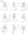
- FIG. 13B shows the center of the fifth resize determination template image at the initial distance, that is, the center positions P1 to P4 and P6 to P9 of the first to fourth, sixth to ninth resize determination template images. It is a figure explaining the distance from position P5.
- the matching position M1 of the first to fifth resizing determination template images When the state of FIG. 13B changes to the state of FIG. 13A, that is, when the tracking subject Hs becomes smaller on the frame image, the matching position M1 of the first to fifth resizing determination template images.
- the positional relationship of M9 to M9 has a higher density than the case shown in FIG. That is, the distance (current distance) from the matching position M5 of the fifth resize determination template image at each of the matching positions M1 to M4 and M6 to M9 of the first to fourth, sixth to ninth resize determination template images.
- the distance (current distance) from the matching position M5 of the fifth resize determination template image at each of the matching positions M1 to M4 and M6 to M9 of the first to fourth, sixth to ninth resize determination template images Are shorter than the corresponding initial distances. Also, the smaller the tracking subject Hs, the shorter the current distance compared to the initial distance.
- the matching position M1 of the first to fifth resizing determination template images When the state of FIG. 13B changes to the state of FIG. 13C, that is, when the tracking subject Hs becomes large on the frame image, the matching position M1 of the first to fifth resizing determination template images.
- the density In the positional relationship of M9 to M9, the density is lower (sparser) than in the case shown in FIG. That is, the distance (current distance) from the matching position M5 of the fifth resize determination template image at each of the matching positions M1 to M4 and M6 to M9 of the first to fourth, sixth to ninth resize determination template images. Is longer than the corresponding initial distance. Further, the larger the tracking subject Hs, the longer the current distance compared to the initial distance.
- the fifth resize determination template at each of the matching positions M1 to M4 and M6 to M9 of the first to fourth, sixth to ninth resize determination template images does not change much from the initial distance corresponding to each.
- step S807 the control device 104 determines whether the change from the initial distance calculated in step S217 or step S222 described above or step S814 or step S819 described later is large in the distance calculated in step S806 (referred to as current distance). Determine whether or not. Specifically, when the current distance / initial distance ⁇ 1.2 or the current distance / initial distance ⁇ 0.76 in the majority of the current distances calculated in step S806, the current distance from the initial distance is It is determined that the change is large. In other cases, it is determined that the change from the initial distance is small at the current distance. When the change from the initial distance is large at the current distance, there is a high possibility that the size of the tracking subject has changed greatly.
- control device 104 determines that the change is large, it makes an affirmative decision in step S807 and proceeds to step S808.
- the control device 104 makes a negative determination in step S807, ends the process of FIG. 11 without changing the size of the template image, and returns to the process of FIG.
- step S808 of FIG. 12 the control device 104 increases the object size when the current distance is longer than the initial distance, and increases the object size when the current distance is shorter than the initial distance. Make it smaller. Further, the control device 104 increases the size change amount as the object size before change is larger, and decreases the size change amount as the object size before change is smaller. Specifically, when the current distance / initial distance ⁇ 1.2, the following equation (24) is used. When the current distance / initial distance ⁇ 0.76, the following equation (25) is used to determine the object size ( Objectsize) is updated.
- step S809 the control device 104 determines whether or not the object size updated in step S808 is larger than a predetermined value (24 pixels in the present embodiment). If the object size is larger than the predetermined value, the control device 104 makes an affirmative decision in step S809 and proceeds to step S815. On the other hand, if the object size is equal to or smaller than the predetermined value, a negative determination is made in step S809 and the process proceeds to step S810.
- step S810 the control device 104 sets the frame image reduction magnification Shuku to 1 and proceeds to step S811.
- step S811 the control device 104 resizes the size of the initial template image recorded in the memory (not shown) in step S214 or S219 using the reciprocal of the reduction magnification Shuku stored in the memory (not shown) in step S213 or S218. Then, the control device 104 resizes the resized initial template image so as to be the object size Objectsize ⁇ Objectsize updated in step S808, and proceeds to step S812.
- step S812 the control device 104 uses the frame image read in step S40, the image having the object size Objectsize ⁇ Objectsize updated in step S808 centered on the tracking subject position specified in step S50 as a composite template image. Update and go to step S813.
- step S813 the control device 104 divides the composite template image generated in step S813 into 3 ⁇ 3 blocks, and calculates the center position of each block. Then, as in the case of step S216 described above, the control device 104 uses the first to ninth resize determination template images as the object size Objectsize ⁇ Objectsize updated in step S808 with the center position of each block as the center. Update as.
- control device 104 increases the size of the template image, and the current distance becomes shorter than the initial distance. If this happens, reduce the size of the template image.
- step S814 the control device 104 determines the center positions of the first to fourth and sixth to ninth resize determination template images updated in step 813 from the center position of the fifth resize determination template image.
- the distance is calculated as the initial distance.
- the control device 104 records the calculated distance in a memory (not shown). Thereafter, the control device 104 ends the process of FIG. 12 and returns to the process of FIG.
- step S815 which proceeds after making an affirmative determination in step S809 described above, the control device 104 calculates the reduction magnification Shuku of the frame image by the above equation (7) using the object size Objectsize updated in step S808. Then, the control device 104 resizes the frame image read in step S40 using the calculated reduction ratio Shuku, and proceeds to step S816. In accordance with this resizing, the coordinates of the tracking subject position identified in step S50 are converted.
- step S816 the control device 104 resizes the size of the initial template image recorded in the memory (not shown) in step S214 or S219 using the reciprocal of the reduction magnification Shuku recorded in the memory (not shown) in step S213 or S218. Then, the control device 104 resizes the resized initial template image so as to be the object size Objectsize ⁇ Objectsize updated in step S808. Furthermore, the control device 104 resizes the resized initial template image using the reduction ratio Shuku calculated in step S815, thereby setting the size of the initial template image to 24 ⁇ 24 pixels and proceeds to step S817.
- step S817 the control device 104 updates an image having a size of 24 ⁇ 24 pixels centered on the tracking subject position in the frame image resized in step S815 as a synthesized template image, and proceeds to step S818.
- step 818 the control device 104 divides the composite template image generated in step S817 into 3 ⁇ 3 blocks, and calculates the center position of each block. Then, as in the case of step S221 described above, the control device 104 updates an image having a size of 24 ⁇ 24 pixels centered on the center position of each block as new first to ninth resize determination template images. To do.
- step S815 to S818 when the object size updated in step S809 is larger than 24 pixels, when the current distance becomes longer than the initial distance, the control device 104 determines the frame image.
- the size of the template image is increased and the current distance becomes shorter than the initial distance, the size of the template image with respect to the frame image is decreased.
- changing the size of the template image includes changing the magnification of the size of the template image with respect to the size of the frame image.
- step S819 the control device 104 determines the center positions of the first to fourth and sixth to ninth resize determination template images updated in step S818 from the center position of the fifth resize determination template image.
- the distance is calculated as the initial distance.
- the control device 104 records the calculated distance in a memory (not shown). Thereafter, the control device 104 ends the process of FIG. 12 and returns to the process of FIG.
- step S90 sets a search area in the template matching process of the next frame.
- the control device 104 sets an area having a size determined based on the template size and the minimum absolute difference sum (that is, the maximum similarity) calculated in step S505 with the tracking subject position as the center.
- the upper end y coordinate (TM_Ystart), the lower end y coordinate (TM_Yend), the left end x coordinate (TM_Xstart), and the right end y coordinate (TM_Xend) of the search area are expressed by the above equations (8) to Calculate according to (15).
- MinZansa uses the minimum absolute difference sum calculated in step S505.
- control device 104 When the search area in the next frame is set in this way, the control device 104 returns to step S40.
- the control device 104 tracks the subject to be tracked in the frame images read one after another by repeating steps S40 to S90.
- the subject tracking device sets the similarity between the control device 104 that sets the search area in the input image (frame image), and the tracking template image (initial template image and composite template image) and the image in the search area.
- the sparseness of the device 104 and the identified matching position that is, the current distance
- a control device 104 that changes the image size of the tracking template image and the resizing determination template image on the basis of the degree of change from the initial distance in the template).
- the size can be changed. Therefore, it is possible to accurately track a subject whose size changes.
- the control device 104 determines that the sparseness of the plurality of identified matching positions has changed by a predetermined value (current distance / initial distance ⁇ 1.2 or current distance / Since the template image size is changed when the initial distance ⁇ 0.76), the size of the template image is erroneously changed greatly even though the size of the tracking subject has not changed much. Can be prevented.
- the control device 104 causes the density of the identified matching positions to change to a higher one (that is, the current distance becomes shorter than the initial distance).
- the size of the template image is reduced and the density of the plurality of identified matching positions is changed to a lower density (that is, the current distance is longer than the initial distance). Since the size of the template image can be reduced when the tracking subject becomes small, the size of the template image can be increased when the tracking subject becomes large.
- the control device 104 has a matching position in which the minimum absolute difference sum is smaller than the determination threshold among the specified matching positions, that is, the similarity is the same. Since a matching position that is higher than a predetermined height is selected and the image size is changed based on the density of the selected matching position, only the matching position where the tracking subject is reliably captured and tracked can be selected. Based on this, the size of the template image can be changed. Accordingly, it is possible to prevent the size of the template image from being changed inappropriately.
- the first to ninth resize determination template images are configured so as to include different portions of the tracking template image (composite template image). Therefore, whether or not the size of the tracking subject has changed can be accurately recognized using the first to ninth resize determination template images.
- the first to ninth resize determination template images are the blocks in the tracking template image (composite template image) divided into 3 ⁇ 3 blocks. Since the image has a predetermined size centered on the center position of B1 to B9, whether or not the size of the tracking subject has changed is accurately determined using the first to ninth resize determination template images. Can be recognized.
- the control device 104 uses the matching position for the fifth resize determination template image centered on the center position P5 of the middle block B5 in the 3 ⁇ 3 block. Since the size of the template image is changed based on the density of the matching positions for the other (first to fourth, sixth to ninth) resize determination template images, the size of the tracking subject It is possible to accurately follow the change in height.
- the control device 104 determines that the template image is determined when the maximum similarity between the fifth resize determination template image and the image in the search area is higher than a predetermined level. Since the configuration is such that the size is changed, the size of the template image can be changed with a sparse density with reference to the matching position where the tracking subject is reliably captured and tracked. Accordingly, it is possible to prevent the size of the template image from being changed inappropriately.
- the subject tracking device includes a control device 104 that sets a search area in the input image (frame image), the similarity between the initial template image and the image in the search area, and the composite template image and the image in the search area.
- the control device 104 that calculates the similarity to each other, the control device 104 that specifies the tracking subject position in the frame image based on the calculated similarity, and the composite template image is updated based on the calculated similarity
- an image obtained by combining the image including the tracking subject position in the input image and the initial template image is used as a new composite template image.
- Control device 104 to be updated, first to ninth resize determination template images, and images in the search area
- the updated composite template image is divided into a plurality of blocks, and an image having a new image size including each block in the input image is updated as a new resize determination template image.
- the image sizes of the initial template image, the combined template image, and the resizing determination template image can be changed in accordance with the change in the image size. Therefore, it is possible to accurately track a subject whose size changes.
- the composite template image is divided into 3 ⁇ 3 blocks, and an image having the same size as the composite template image with the center position of each of the divided blocks as the center is determined as the first to ninth resize determinations.
- An example of generating a template image for use has been described. However, it is not limited to 3 ⁇ 3, and the synthesized template image may be divided into other numbers of blocks, and an image including each divided block may be generated as a resize determination template image.
- the synthesized template image Tg may be divided into 2 ⁇ 2 blocks B11 to B14.
- the control device 104 includes blocks B11 to B14, respectively, and an image having the same size as the synthesized template image Tg is used for the eleventh to fourteenth resize determination. Template images Tr11 to Tr14 are generated.
- the center positions of the blocks B11 to B14 do not necessarily have to be the centers of the eleventh to fourteenth resize determination template images Tr11 to Tr14.
- the resize determination template image is preferably generated so as to include the edge portion of the tracking subject and not to include the background portion (portion other than the tracking subject). By doing so, it is possible to follow the edge portion of the tracking subject using the resize determination template image, so that it is possible to recognize whether or not the size of the tracking subject has changed.
- the control device 104 calculates and stores the distance from the center position of the combined template image as the initial distance for each of the center positions of the eleventh to fourteenth resize determination template images Tr11 to Tr14.
- the control device 104 makes an affirmative determination in step S805 when the similarity (that is, the maximum similarity) at the matching position of the combined template image Tg is higher than a predetermined level.
- the control device 104 calculates the distance from the matching position of the combined template image Tg as the current distance for the matching positions of the eleventh to fourteenth resize determination template images Tr11 to Tr14. Thereafter, the control device 104 changes the template size in the same manner as in the above-described embodiment.
- the initial template image may be generated by other methods.
- the control device 104 prompts the user to specify the tracking subject area in the frame image, and generates an initial template image by cutting out the image in the area input by the user operating the operation member 101. May be.
- Modification 7 In the above-described embodiment, the example in which the control device 104 performs subject tracking for a through image has been described. However, when the camera 100 has a moving image shooting function, the control device 104 may perform subject tracking between frames of a captured moving image instead of the through image.
Landscapes
- Engineering & Computer Science (AREA)
- Theoretical Computer Science (AREA)
- General Physics & Mathematics (AREA)
- Physics & Mathematics (AREA)
- Computer Vision & Pattern Recognition (AREA)
- Multimedia (AREA)
- Evolutionary Computation (AREA)
- Artificial Intelligence (AREA)
- Software Systems (AREA)
- Databases & Information Systems (AREA)
- Medical Informatics (AREA)
- General Health & Medical Sciences (AREA)
- Data Mining & Analysis (AREA)
- Health & Medical Sciences (AREA)
- Computing Systems (AREA)
- Bioinformatics & Computational Biology (AREA)
- General Engineering & Computer Science (AREA)
- Evolutionary Biology (AREA)
- Bioinformatics & Cheminformatics (AREA)
- Life Sciences & Earth Sciences (AREA)
- Image Analysis (AREA)
- Studio Devices (AREA)
Abstract
Description
本発明の第2の態様によると、第1の態様の被写体追尾装置において、サイズ変更部は、マッチング位置特定部で特定した複数のマッチング位置の疎密度合いが所定以上変化した場合に、追尾用テンプレート画像およびリサイズ判定用テンプレート画像の画像サイズを変更することが好ましい。
本発明の第3の態様によると、第1または2の態様の被写体追尾装置において、サイズ変更部は、マッチング位置特定部で特定した複数のマッチング位置の密度が高い方へ変化した場合に画像サイズを小さくし、マッチング位置特定部で特定した複数のマッチング位置の密度が低い方へ変化した場合に画像サイズを大きくすることが好ましい。
本発明の第4の態様によると、第1~3のいずれか一態様の被写体追尾装置において、サイズ変更部は、マッチング位置特定部で特定した複数のマッチング位置のうち、第2の類似度演算部で演算した類似度が所定以上の高さであるマッチング位置を選択し、選択したマッチング位置の疎密度合いに基づいて画像サイズを変更することが好ましい。
本発明の第5の態様によると、第1~4のいずれか一態様の被写体追尾装置において、複数枚のリサイズ判定用テンプレート画像は、追尾用テンプレート画像の異なる一部分をそれぞれ含む画像であることが好ましい。
本発明の第6の態様によると、第5の態様の被写体追尾装置において、複数枚のリサイズ判定用テンプレート画像は、複数のブロックに分割された追尾用テンプレート画像において、それぞれ、各ブロックの中心位置を中心とした所定サイズの画像であることが好ましい。
本発明の第7の態様によると、第6の態様の被写体追尾装置において、サイズ変更部は、複数のブロックにおける真ん中のブロックの中心位置を中心としたリサイズ判定用テンプレート画像についてのマッチング位置を基準とした、その他のリサイズ判定用テンプレート画像についてのマッチング位置の疎密度合いに基づいて追尾用テンプレート画像およびリサイズ判定用テンプレート画像の画像サイズを変更することが好ましい。
本発明の第8の態様によると、第7の態様の被写体追尾装置において、サイズ変更部は、複数のブロックにおける真ん中のブロックの中心位置を中心としたリサイズ判定用テンプレート画像と探索領域内の画像との最大類似度が所定以上の高さである場合に、追尾用テンプレート画像およびリサイズ判定用テンプレート画像の画像サイズを変更するか否かを判定することが好ましい。
本発明の第9の態様によると、被写体追尾装置は、入力画像内に探索領域を設定する探索領域設定部と、初期テンプレート画像と探索領域内の画像との類似度、および合成テンプレート画像と探索領域内の画像との類似度を、それぞれ演算する第1の類似度演算部と、第1の類似度演算部で演算した類似度に基づいて、入力画像内における追尾被写体位置を特定する被写体位置特定部と、第1の類似度演算部で演算した類似度に基づいて、合成テンプレート画像を更新するか否かを判定する更新判定部と、更新判定部が合成テンプレート画像を更新すると判定した場合には、入力画像における追尾被写体位置を含む画像と初期テンプレート画像とを合成した画像を、新たな合成テンプレート画像として更新する更新部と、複数枚のリサイズ判定用テンプレート画像と探索領域内の画像との類似度をそれぞれ演算する第2の類似度演算部と、第2の類似度演算部で演算した類似度に基づいて、入力画像内における複数枚のリサイズ判定用テンプレート画像のマッチング位置をそれぞれ特定するマッチング位置特定部と、マッチング位置特定部で特定した複数のマッチング位置の疎密度合いに基づいて、初期テンプレート画像と合成テンプレート画像とリサイズ判定用テンプレート画像との画像サイズを変更するか否かを判定するサイズ変更判定部と、サイズ変更判定部が画像サイズを変更すると判定した場合には、初期テンプレート画像の画像サイズを新たな画像サイズに変更するサイズ変更部と、を備え、更新部は、サイズ変更判定部が画像サイズを変更すると判定した場合には、入力画像における追尾被写体位置を含む新たな画像サイズの画像を、新たな合成テンプレート画像として更新し、さらに、更新した合成テンプレート画像を複数のブロックに分割し、入力画像における各ブロックを含む新たな画像サイズの画像を、新たなリサイズ判定用テンプレート画像として更新する。
本発明の第10の態様によると、被写体追尾装置は、テンプレート画像に基づいて、画像内の特定被写体を追尾する追尾手段と、特定被写体の大きさの変化を検出する検出手段と、検出手段が、特定被写体の大きさが所定量以上変化したと検出した場合に、テンプレート画像を更新する更新手段と、を備える。
本発明の第11の態様によると、カメラは、第1~10のいずれか一態様の被写体追尾装置を備える。
118 < aveCb < 138 ・・・(1)
sigCb < abs(aveCb-128)+3 ・・・(2)
thCb = α×sigCb×[{abs(aveCb-128)+3}/sigCb]1/2×[10/{abs(aveCb-128)+0.1}]1/2 ・・・(3)
なお、式(2)および(3)において、absは絶対値をとる関数である。また、式(3)において、αは例えば0.6とする。
IM=ΣΣ{(x-xg)2+(y-yg)2) ・・・(4)
なお、式(4)において、(x,y)は、マスクの画素の座標であり、(xg,yg)は、追尾被写体位置の座標である。
評価値=(マスク面積)β/IM ・・・(5)
なお、式(5)においては、βの値は1より大きな値が好ましく、例えば1.5とする。
Objectsize=floor(Rect/3)×3 ・・・(6)
なお、式(6)において、floorは小数点以下の切り捨てを行う関数である。
Shuku=24/ObjectSize ・・・(7)
Search=TM_ImageWidth×Keisu ・・・(8)
If(ObjectSize>=60) →Geta=50
else Geta=24 ・・・(9)
Geta1=Geta×Shuku ・・・(10)
SearchWidth=Minzansa×Search+Geta1 ・・・(11)
TM_Ystart=ObjectY-(SearchWidth+1)-TempSize/2 ・・・(12)
TM_Yend=ObjectY+SearchWidth+TempSize/2 ・・・(13)
TM_Xstart=ObjectX-(SearchWidth+1)-TempSize/2 ・・・(14)
TM_Xend=ObjectX+SearchWidth+TempSize/2 ・・・(15)
Kyori(x,y)=Kyori0+K(|x-Mx×Shuku|+|y-My×Shuku|) ・・・(16)
なお、式(16)において、(x,y)は、探索エリア内の各画素の座標であり、Mxは前フレームで特定された追尾被写体位置のx座標、Myは前フレームで特定された追尾被写体位置のy座標である。また、本実施形態では、Kyori0=1.0、K=0.05とする。
SADall=1/N(GainY×SADY+GainCb×SADCb+GainCr×SADCb) ・・・(17)
なお、式(17)において、本実施形態では、GainY=0.1、GainCb=1.5、GainCr=1.5とする。また、NはSADの正規化係数であり、N=Tempsize×Tempsize×255とする。
Objx=Mx+Tempsize/2 ・・・(18)
Objy=My+Tempsize/2 ・・・(19)
Obj_YStart=My/Shuku ・・・(20)
Obj_YEnd=(My+Tempsize-1)/Shuku ・・・(21)
Obj_XStart=Mx/Shuku ・・・(22)
Obj_XEnd=(Mx+Tempsize-1)/Shuku ・・・(23)
条件(1)・・・上記最小絶対差分和があらかじめ設定されている判定閾値よりも小さい(すなわち最大類似度が所定以上の高さである)こと
条件(2)・・・所定の回数(例えば3回)以上連続して、同じテンプレート画像から生成された類似度マップから最大類似度が算出されたこと
If(ObjectSize≧240) → ObjectSize=240
elseif(ObjectSize≧120) → ObjectSize=ObjectSize+15
elseif(ObjectSize≧60) → ObjectSize=ObjectSize+12
elseif(ObjectSize≧48) → ObjectSize=ObjectSize+9
elseif(ObjectSize≧27) → ObjectSize=ObjectSize+6
else →ObjectSize=ObjectSize+3 ・・・(24)
If(ObjectSize≧105) → ObjectSize=ObjectSize-15
elseif(ObjectSize≧72) → ObjectSize=ObjectSize-12
elseif(ObjectSize≧33) → ObjectSize=ObjectSize-9
elseif(ObjectSize≧24) → ObjectSize=ObjectSize-6
elseif(ObjectSize≦6) → ObjectSize=6
else →ObjectSize=ObjectSize-3 ・・・(25)
(1)被写体追尾装置は、入力画像(フレーム画像)内に探索エリアを設定する制御装置104と、追尾用テンプレート画像(初期テンプレート画像および合成テンプレート画像)と探索エリア内の画像との類似度を演算する制御装置104と、当該演算した類似度に基づいて、フレーム画像内における追尾被写体位置を特定する制御装置104と、合成テンプレート画像に基づいて生成された第1~第9リサイズ判定用テンプレート画像と探索エリア内の画像との類似度をそれぞれ演算する制御装置104と、当該演算した類似度に基づいて、フレーム画像内における第1~第9リサイズ判定用テンプレート画像のマッチング位置をそれぞれ特定する制御装置104と、上記特定したマッチング位置の疎密度合い(すなわち、上記現在距離における上記初期距離からの変化度合い)に基づいて、追尾用テンプレート画像およびリサイズ判定用テンプレート画像の画像サイズを変更する制御装置104と、を備えるので、追尾被写体の大きさの変化に応じてテンプレート画像のサイズを変更することができる。したがって、大きさが変化する被写体を精度よく追尾することができる。
上述した実施の形態では、合成テンプレート画像を3×3のブロックに分割し、分割した各ブロックの中心位置を中心とし、合成テンプレート画像と同一のサイズである画像を、第1~第9リサイズ判定用テンプレート画像として生成する例について説明した。しかしながら、3×3に限らず、その他の個数のブロックに合成テンプレート画像を分割し、分割した各ブロックを含む画像をリサイズ判定用テンプレート画像として生成してもよい。
上述した実施の形態では、追尾被写体の大きさを示すオブジェクトサイズが24画素よりも大きい場合は、縮小倍率Shukuで縮小したフレーム画像において24×24画素のテンプレート画像を生成する例について説明した。しかしながら、テンプレートマッチング処理で扱えるテンプレート画像の大きさの最大値に制限がない場合には、オブジェクトサイズの大きさに係らず、Objectsize×Objectsizeのテンプレート画像を生成するようにしてもよい。
上述した実施の形態では、追尾被写体位置を特定するために用いる追尾用テンプレート画像として、初期テンプレート画像および合成テンプレート画像を用いる例について説明した。しかしながら、追尾用テンプレート画像として、初期テンプレート画像のみ、または合成テンプレート画像のみを用いるようにしてもよい。また例えば、現フレームにおけるマッチング領域内の画像を次フレームにおける追尾用テンプレート画像として用いるようにしてもよい。
上述した実施の形態では、初期テンプレート画像および合成テンプレート画像のサイズと、リサイズ判定用テンプレート画像のサイズとを同一サイズとする例について説明した。しかしながら、初期テンプレート画像および合成テンプレート画像のサイズと、リサイズ判定用テンプレート画像のサイズとが異なっていてもよい。
上述した実施の形態では、制御装置104は、フレーム画像に対して行った2値化処理およびラベリング処理の結果を用いて、初期テンプレート画像を生成する例について説明した。しかしながら、他の方法によって初期テンプレート画像を生成してもよい。例えば、制御装置104は、使用者に対してフレーム画像内における追尾被写体エリアの指定を促し、使用者が操作部材101を操作して入力したエリア内の画像を切り出すことにより、初期テンプレート画像を生成してもよい。
上述した実施の形態では、画像のリサイズ方法としてバイリニア法を用いる例について説明した。しかしながら、画像のリサイズ方法として、ニアリストネイバー法、またはバイキュービック法などを用いるようにしてもよい。
上述した実施の形態では、制御装置104は、スルー画を対象として被写体追尾を行う例について説明した。しかしながら、カメラ100が動画撮影機能を備えている場合には、制御装置104は、スルー画ではなく、撮影済みの動画のフレーム間で被写体追尾を行うようにしてもよい。
上述した実施の形態では、カメラ100が備える制御装置104が図2に示す処理を実行して被写体追尾を行う例について説明した。しかしながら、図2に示す処理を実行するためのプログラムをパソコンなどその他の端末に記録して、当該端末上で処理を実行することも可能である。この場合、カメラで撮影した動画像データを端末側に取り込んで、これを対象に処理を行うようにすれば、動画のフレーム間で被写体追尾を行うことが可能となる。また、本発明はカメラ付き携帯電話などに適用することも可能である。
日本国特許出願2012年第158795号(2012年7月17日出願)
101…操作部材
102…レンズ
103…撮像素子
104…制御装置
105…メモリカードスロット
106…モニタ
Claims (11)
- 入力画像内に探索領域を設定する探索領域設定部と、
追尾用テンプレート画像と前記探索領域内の画像との類似度を演算する第1の類似度演算部と、
前記第1の類似度演算部で演算した類似度に基づいて、前記入力画像内における追尾被写体位置を特定する被写体位置特定部と、
前記追尾用テンプレート画像に基づいて生成された複数枚のリサイズ判定用テンプレート画像と前記探索領域内の画像との類似度をそれぞれ演算する第2の類似度演算部と、
前記第2の類似度演算部で演算した類似度に基づいて、前記入力画像内における前記複数枚のリサイズ判定用テンプレート画像のマッチング位置をそれぞれ特定するマッチング位置特定部と、
前記マッチング位置特定部で特定した複数のマッチング位置の疎密度合いに基づいて、前記追尾用テンプレート画像および前記リサイズ判定用テンプレート画像の画像サイズを変更するサイズ変更部と、
を備える被写体追尾装置。 - 請求項1に記載の被写体追尾装置において、
前記サイズ変更部は、前記マッチング位置特定部で特定した複数のマッチング位置の疎密度合いが所定以上変化した場合に、前記追尾用テンプレート画像および前記リサイズ判定用テンプレート画像の画像サイズを変更する被写体追尾装置。 - 請求項1または2に記載の被写体追尾装置において、
前記サイズ変更部は、前記マッチング位置特定部で特定した複数のマッチング位置の密度が高い方へ変化した場合に前記画像サイズを小さくし、前記マッチング位置特定部で特定した複数のマッチング位置の密度が低い方へ変化した場合に前記画像サイズを大きくする被写体追尾装置。 - 請求項1~3のいずれか一項に記載の被写体追尾装置において、
前記サイズ変更部は、前記マッチング位置特定部で特定した複数のマッチング位置のうち、前記第2の類似度演算部で演算した類似度が所定以上の高さであるマッチング位置を選択し、前記選択したマッチング位置の疎密度合いに基づいて前記画像サイズを変更する被写体追尾装置。 - 請求項1~4のいずれか一項に記載の被写体追尾装置において、
前記複数枚のリサイズ判定用テンプレート画像は、前記追尾用テンプレート画像の異なる一部分をそれぞれ含む画像である被写体追尾装置。 - 請求項5に記載の被写体追尾装置において、
前記複数枚のリサイズ判定用テンプレート画像は、複数のブロックに分割された前記追尾用テンプレート画像において、それぞれ、前記各ブロックの中心位置を中心とした所定サイズの画像である被写体追尾装置。 - 請求項6に記載の被写体追尾装置において、
前記サイズ変更部は、前記複数のブロックにおける真ん中のブロックの中心位置を中心としたリサイズ判定用テンプレート画像についてのマッチング位置を基準とした、その他のリサイズ判定用テンプレート画像についてのマッチング位置の疎密度合いに基づいて前記追尾用テンプレート画像および前記リサイズ判定用テンプレート画像の画像サイズを変更する被写体追尾装置。 - 請求項7に記載の被写体追尾装置において、
前記サイズ変更部は、前記複数のブロックにおける真ん中のブロックの中心位置を中心としたリサイズ判定用テンプレート画像と前記探索領域内の画像との最大類似度が所定以上の高さである場合に、前記追尾用テンプレート画像および前記リサイズ判定用テンプレート画像の画像サイズを変更するか否かを判定する被写体追尾装置。 - 入力画像内に探索領域を設定する探索領域設定部と、
初期テンプレート画像と前記探索領域内の画像との類似度、および合成テンプレート画像と前記探索領域内の画像との類似度を、それぞれ演算する第1の類似度演算部と、
前記第1の類似度演算部で演算した類似度に基づいて、前記入力画像内における追尾被写体位置を特定する被写体位置特定部と、
前記第1の類似度演算部で演算した類似度に基づいて、前記合成テンプレート画像を更新するか否かを判定する更新判定部と、
前記更新判定部が前記合成テンプレート画像を更新すると判定した場合には、前記入力画像における前記追尾被写体位置を含む画像と前記初期テンプレート画像とを合成した画像を、新たな合成テンプレート画像として更新する更新部と、
複数枚のリサイズ判定用テンプレート画像と前記探索領域内の画像との類似度をそれぞれ演算する第2の類似度演算部と、
前記第2の類似度演算部で演算した類似度に基づいて、前記入力画像内における前記複数枚のリサイズ判定用テンプレート画像のマッチング位置をそれぞれ特定するマッチング位置特定部と、
前記マッチング位置特定部で特定した複数のマッチング位置の疎密度合いに基づいて、前記初期テンプレート画像と前記合成テンプレート画像と前記リサイズ判定用テンプレート画像との画像サイズを変更するか否かを判定するサイズ変更判定部と、
前記サイズ変更判定部が前記画像サイズを変更すると判定した場合には、前記初期テンプレート画像の画像サイズを新たな画像サイズに変更するサイズ変更部と、
を備え、
前記更新部は、前記サイズ変更判定部が前記画像サイズを変更すると判定した場合には、前記入力画像における前記追尾被写体位置を含む前記新たな画像サイズの画像を、新たな合成テンプレート画像として更新し、さらに、前記更新した合成テンプレート画像を複数のブロックに分割し、前記入力画像における前記各ブロックを含む前記新たな画像サイズの画像を、新たなリサイズ判定用テンプレート画像として更新する被写体追尾装置。 - テンプレート画像に基づいて、画像内の特定被写体を追尾する追尾手段と、
前記特定被写体の大きさの変化を検出する検出手段と、
前記検出手段が、前記特定被写体の大きさが所定量以上変化したと検出した場合に、前記テンプレート画像を更新する更新手段と、
を備える被写体追尾装置。 - 請求項1~10のいずれか一項に記載の被写体追尾装置を備えるカメラ。
Priority Applications (3)
| Application Number | Priority Date | Filing Date | Title |
|---|---|---|---|
| JP2014525850A JP6323330B2 (ja) | 2012-07-17 | 2013-07-17 | 被写体追尾装置およびカメラ |
| US14/413,282 US9563967B2 (en) | 2012-07-17 | 2013-07-17 | Photographic subject tracking device and camera |
| CN201380048010.6A CN104641398B (zh) | 2012-07-17 | 2013-07-17 | 被拍摄体跟踪装置以及相机 |
Applications Claiming Priority (2)
| Application Number | Priority Date | Filing Date | Title |
|---|---|---|---|
| JP2012158795 | 2012-07-17 | ||
| JP2012-158795 | 2012-07-17 |
Publications (1)
| Publication Number | Publication Date |
|---|---|
| WO2014014031A1 true WO2014014031A1 (ja) | 2014-01-23 |
Family
ID=49948855
Family Applications (1)
| Application Number | Title | Priority Date | Filing Date |
|---|---|---|---|
| PCT/JP2013/069427 Ceased WO2014014031A1 (ja) | 2012-07-17 | 2013-07-17 | 被写体追尾装置およびカメラ |
Country Status (4)
| Country | Link |
|---|---|
| US (1) | US9563967B2 (ja) |
| JP (2) | JP6323330B2 (ja) |
| CN (2) | CN107610153B (ja) |
| WO (1) | WO2014014031A1 (ja) |
Cited By (2)
| Publication number | Priority date | Publication date | Assignee | Title |
|---|---|---|---|---|
| WO2023105598A1 (ja) * | 2021-12-07 | 2023-06-15 | 株式会社日立国際電気 | 画像処理装置、画像処理システム及び画像処理方法 |
| WO2025120230A1 (en) | 2023-12-07 | 2025-06-12 | T-Curx Gmbh | Method of producing leukocytes expressing artificial antigen receptors |
Families Citing this family (11)
| Publication number | Priority date | Publication date | Assignee | Title |
|---|---|---|---|---|
| DE102014224557A1 (de) * | 2014-12-01 | 2016-06-02 | Osram Gmbh | Bildverarbeitung mittels Kreuzkorrelation |
| US10017115B2 (en) * | 2015-11-11 | 2018-07-10 | Ford Global Technologies, Llc | Trailer monitoring system and method |
| JP6700791B2 (ja) * | 2016-01-05 | 2020-05-27 | キヤノン株式会社 | 情報処理装置、情報処理方法及びプログラム |
| CN106228194B (zh) * | 2016-08-05 | 2018-09-18 | 腾讯科技(深圳)有限公司 | 图像查找方法和装置 |
| CN107240118B (zh) * | 2017-05-19 | 2020-10-09 | 成都信息工程大学 | 一种基于rgb颜色直方图的判别式跟踪方法 |
| US10332272B2 (en) * | 2017-08-07 | 2019-06-25 | Caterpillar Inc. | Systems and methods for testing an automatic perception system |
| US11457795B2 (en) * | 2017-11-06 | 2022-10-04 | Hoya Corporation | Processor for electronic endoscope and electronic endoscope system |
| US11398072B1 (en) * | 2019-12-16 | 2022-07-26 | Siemens Healthcare Gmbh | Method of obtaining a set of values for a respective set of parameters for use in a physically based path tracing process and a method of rendering using a physically based path tracing process |
| US11276199B2 (en) * | 2020-02-17 | 2022-03-15 | The Boeing Company | Image template based tracking |
| KR102992345B1 (ko) | 2020-08-31 | 2026-07-21 | 삼성전자주식회사 | 전자 장치 및 그 제어 방법 |
| JP7577490B2 (ja) * | 2020-09-18 | 2024-11-05 | キヤノン株式会社 | 追尾装置、追尾方法、プログラム |
Citations (3)
| Publication number | Priority date | Publication date | Assignee | Title |
|---|---|---|---|---|
| JP2006146922A (ja) * | 2004-11-17 | 2006-06-08 | Samsung Electronics Co Ltd | テンプレート方式の顔検出方法 |
| WO2008114683A1 (ja) * | 2007-03-16 | 2008-09-25 | Nikon Corporation | 被写体追跡用コンピュータプログラム製品、被写体追跡装置、およびカメラ |
| JP2010157792A (ja) * | 2008-12-26 | 2010-07-15 | Nikon Corp | 被写体追跡装置 |
Family Cites Families (5)
| Publication number | Priority date | Publication date | Assignee | Title |
|---|---|---|---|---|
| JP3768073B2 (ja) | 1999-06-15 | 2006-04-19 | 株式会社日立国際電気 | 物体追跡方法及び物体追跡装置 |
| JP4214926B2 (ja) * | 2004-03-04 | 2009-01-28 | 株式会社ニコン | 電子スチルカメラ |
| JP2009053815A (ja) * | 2007-08-24 | 2009-03-12 | Nikon Corp | 被写体追跡プログラム、および被写体追跡装置 |
| CN100568262C (zh) * | 2007-12-29 | 2009-12-09 | 浙江工业大学 | 基于多摄像机信息融合的人脸识别检测装置 |
| JP2013055424A (ja) * | 2011-09-01 | 2013-03-21 | Sony Corp | 撮影装置、パターン検出装置、および電子機器 |
-
2013
- 2013-07-17 JP JP2014525850A patent/JP6323330B2/ja active Active
- 2013-07-17 CN CN201710826974.9A patent/CN107610153B/zh active Active
- 2013-07-17 US US14/413,282 patent/US9563967B2/en active Active
- 2013-07-17 CN CN201380048010.6A patent/CN104641398B/zh active Active
- 2013-07-17 WO PCT/JP2013/069427 patent/WO2014014031A1/ja not_active Ceased
-
2018
- 2018-04-12 JP JP2018076545A patent/JP6763417B2/ja active Active
Patent Citations (3)
| Publication number | Priority date | Publication date | Assignee | Title |
|---|---|---|---|---|
| JP2006146922A (ja) * | 2004-11-17 | 2006-06-08 | Samsung Electronics Co Ltd | テンプレート方式の顔検出方法 |
| WO2008114683A1 (ja) * | 2007-03-16 | 2008-09-25 | Nikon Corporation | 被写体追跡用コンピュータプログラム製品、被写体追跡装置、およびカメラ |
| JP2010157792A (ja) * | 2008-12-26 | 2010-07-15 | Nikon Corp | 被写体追跡装置 |
Cited By (4)
| Publication number | Priority date | Publication date | Assignee | Title |
|---|---|---|---|---|
| WO2023105598A1 (ja) * | 2021-12-07 | 2023-06-15 | 株式会社日立国際電気 | 画像処理装置、画像処理システム及び画像処理方法 |
| JPWO2023105598A1 (ja) * | 2021-12-07 | 2023-06-15 | ||
| JP7631553B2 (ja) | 2021-12-07 | 2025-02-18 | 株式会社国際電気 | 画像処理装置、画像処理システム及び画像処理方法 |
| WO2025120230A1 (en) | 2023-12-07 | 2025-06-12 | T-Curx Gmbh | Method of producing leukocytes expressing artificial antigen receptors |
Also Published As
| Publication number | Publication date |
|---|---|
| JP6323330B2 (ja) | 2018-05-16 |
| CN104641398A (zh) | 2015-05-20 |
| CN107610153B (zh) | 2020-10-30 |
| JPWO2014014031A1 (ja) | 2016-07-07 |
| JP6763417B2 (ja) | 2020-09-30 |
| US20150356743A1 (en) | 2015-12-10 |
| CN104641398B (zh) | 2017-10-13 |
| CN107610153A (zh) | 2018-01-19 |
| US9563967B2 (en) | 2017-02-07 |
| JP2018136978A (ja) | 2018-08-30 |
Similar Documents
| Publication | Publication Date | Title |
|---|---|---|
| JP6323330B2 (ja) | 被写体追尾装置およびカメラ | |
| EP4200799B1 (en) | Spatiotemporal recycling network | |
| KR101036787B1 (ko) | 움직임 벡터 연산 방법과 이 방법을 이용한 손 떨림 보정장치, 촬상 장치, 및 동영상 생성 장치 | |
| US9082198B2 (en) | Method for creating automatic cinemagraphs on an imagine device | |
| JP6043293B2 (ja) | 画像処理装置、撮像装置および画像処理方法 | |
| JP4798259B2 (ja) | 被写体追尾装置、およびカメラ | |
| WO2022160857A1 (zh) | 图像处理方法及装置、计算机可读存储介质和电子设备 | |
| JP4141968B2 (ja) | 画像処理装置、画像処理方法およびプログラム | |
| KR20180102639A (ko) | 화상 처리 장치, 화상 처리 방법, 화상 처리 프로그램 및 기억 매체 | |
| JP2017229061A (ja) | 画像処理装置およびその制御方法、ならびに撮像装置 | |
| CN113935934A (zh) | 图像处理方法、装置、电子设备和计算机可读存储介质 | |
| CN113807124B (zh) | 图像处理方法、装置、存储介质及电子设备 | |
| JP5994493B2 (ja) | 動画像前景切抜き装置、方法、およびプログラム | |
| JP2010020602A (ja) | 画像マッチング装置、およびカメラ | |
| JP5691617B2 (ja) | 被写体特定装置、および被写体追尾装置 | |
| JP2013182478A (ja) | 被写体追尾装置、被写体追尾方法およびカメラ | |
| JP2014036429A (ja) | 被写体追尾装置、およびカメラ | |
| CN115567783B (zh) | 一种图像处理方法 | |
| CN114549301B (zh) | 图像拼接方法及装置 | |
| JP6044123B2 (ja) | 被写体追尾装置および電子カメラ並びに被写体追尾プログラム | |
| KR20250068712A (ko) | 최적화된 지오메트리 캘리브레이션 및 이미지 기반 시각적 피처들에 의해 다중 카메라 시스템에서의 스무스 연속 주밍 | |
| JP2013182479A (ja) | 被写体追尾装置、被写体追尾方法およびカメラ | |
| JP5029647B2 (ja) | 被写体追尾装置、およびカメラ | |
| JP5146223B2 (ja) | プログラム、カメラ、画像処理装置および画像の輪郭抽出方法 | |
| JP6622546B2 (ja) | 画像処理装置及び方法 |
Legal Events
| Date | Code | Title | Description |
|---|---|---|---|
| 121 | Ep: the epo has been informed by wipo that ep was designated in this application |
Ref document number: 13820227 Country of ref document: EP Kind code of ref document: A1 |
|
| ENP | Entry into the national phase |
Ref document number: 2014525850 Country of ref document: JP Kind code of ref document: A |
|
| NENP | Non-entry into the national phase |
Ref country code: DE |
|
| WWE | Wipo information: entry into national phase |
Ref document number: 14413282 Country of ref document: US |
|
| 122 | Ep: pct application non-entry in european phase |
Ref document number: 13820227 Country of ref document: EP Kind code of ref document: A1 |