WO2014010298A1 - Device for controlling hybrid vehicle and method for controlling hybrid vehicle - Google Patents
Device for controlling hybrid vehicle and method for controlling hybrid vehicle Download PDFInfo
- Publication number
- WO2014010298A1 WO2014010298A1 PCT/JP2013/062731 JP2013062731W WO2014010298A1 WO 2014010298 A1 WO2014010298 A1 WO 2014010298A1 JP 2013062731 W JP2013062731 W JP 2013062731W WO 2014010298 A1 WO2014010298 A1 WO 2014010298A1
- Authority
- WO
- WIPO (PCT)
- Prior art keywords
- engine
- idle
- control
- motor
- idle control
- Prior art date
Links
Images


Classifications
-
- B—PERFORMING OPERATIONS; TRANSPORTING
- B60—VEHICLES IN GENERAL
- B60W—CONJOINT CONTROL OF VEHICLE SUB-UNITS OF DIFFERENT TYPE OR DIFFERENT FUNCTION; CONTROL SYSTEMS SPECIALLY ADAPTED FOR HYBRID VEHICLES; ROAD VEHICLE DRIVE CONTROL SYSTEMS FOR PURPOSES NOT RELATED TO THE CONTROL OF A PARTICULAR SUB-UNIT
- B60W20/00—Control systems specially adapted for hybrid vehicles
- B60W20/10—Controlling the power contribution of each of the prime movers to meet required power demand
-
- B—PERFORMING OPERATIONS; TRANSPORTING
- B60—VEHICLES IN GENERAL
- B60K—ARRANGEMENT OR MOUNTING OF PROPULSION UNITS OR OF TRANSMISSIONS IN VEHICLES; ARRANGEMENT OR MOUNTING OF PLURAL DIVERSE PRIME-MOVERS IN VEHICLES; AUXILIARY DRIVES FOR VEHICLES; INSTRUMENTATION OR DASHBOARDS FOR VEHICLES; ARRANGEMENTS IN CONNECTION WITH COOLING, AIR INTAKE, GAS EXHAUST OR FUEL SUPPLY OF PROPULSION UNITS IN VEHICLES
- B60K6/00—Arrangement or mounting of plural diverse prime-movers for mutual or common propulsion, e.g. hybrid propulsion systems comprising electric motors and internal combustion engines ; Control systems therefor, i.e. systems controlling two or more prime movers, or controlling one of these prime movers and any of the transmission, drive or drive units Informative references: mechanical gearings with secondary electric drive F16H3/72; arrangements for handling mechanical energy structurally associated with the dynamo-electric machine H02K7/00; machines comprising structurally interrelated motor and generator parts H02K51/00; dynamo-electric machines not otherwise provided for in H02K see H02K99/00
- B60K6/20—Arrangement or mounting of plural diverse prime-movers for mutual or common propulsion, e.g. hybrid propulsion systems comprising electric motors and internal combustion engines ; Control systems therefor, i.e. systems controlling two or more prime movers, or controlling one of these prime movers and any of the transmission, drive or drive units Informative references: mechanical gearings with secondary electric drive F16H3/72; arrangements for handling mechanical energy structurally associated with the dynamo-electric machine H02K7/00; machines comprising structurally interrelated motor and generator parts H02K51/00; dynamo-electric machines not otherwise provided for in H02K see H02K99/00 the prime-movers consisting of electric motors and internal combustion engines, e.g. HEVs
- B60K6/42—Arrangement or mounting of plural diverse prime-movers for mutual or common propulsion, e.g. hybrid propulsion systems comprising electric motors and internal combustion engines ; Control systems therefor, i.e. systems controlling two or more prime movers, or controlling one of these prime movers and any of the transmission, drive or drive units Informative references: mechanical gearings with secondary electric drive F16H3/72; arrangements for handling mechanical energy structurally associated with the dynamo-electric machine H02K7/00; machines comprising structurally interrelated motor and generator parts H02K51/00; dynamo-electric machines not otherwise provided for in H02K see H02K99/00 the prime-movers consisting of electric motors and internal combustion engines, e.g. HEVs characterised by the architecture of the hybrid electric vehicle
- B60K6/48—Parallel type
-
- B—PERFORMING OPERATIONS; TRANSPORTING
- B60—VEHICLES IN GENERAL
- B60K—ARRANGEMENT OR MOUNTING OF PROPULSION UNITS OR OF TRANSMISSIONS IN VEHICLES; ARRANGEMENT OR MOUNTING OF PLURAL DIVERSE PRIME-MOVERS IN VEHICLES; AUXILIARY DRIVES FOR VEHICLES; INSTRUMENTATION OR DASHBOARDS FOR VEHICLES; ARRANGEMENTS IN CONNECTION WITH COOLING, AIR INTAKE, GAS EXHAUST OR FUEL SUPPLY OF PROPULSION UNITS IN VEHICLES
- B60K6/00—Arrangement or mounting of plural diverse prime-movers for mutual or common propulsion, e.g. hybrid propulsion systems comprising electric motors and internal combustion engines ; Control systems therefor, i.e. systems controlling two or more prime movers, or controlling one of these prime movers and any of the transmission, drive or drive units Informative references: mechanical gearings with secondary electric drive F16H3/72; arrangements for handling mechanical energy structurally associated with the dynamo-electric machine H02K7/00; machines comprising structurally interrelated motor and generator parts H02K51/00; dynamo-electric machines not otherwise provided for in H02K see H02K99/00
- B60K6/20—Arrangement or mounting of plural diverse prime-movers for mutual or common propulsion, e.g. hybrid propulsion systems comprising electric motors and internal combustion engines ; Control systems therefor, i.e. systems controlling two or more prime movers, or controlling one of these prime movers and any of the transmission, drive or drive units Informative references: mechanical gearings with secondary electric drive F16H3/72; arrangements for handling mechanical energy structurally associated with the dynamo-electric machine H02K7/00; machines comprising structurally interrelated motor and generator parts H02K51/00; dynamo-electric machines not otherwise provided for in H02K see H02K99/00 the prime-movers consisting of electric motors and internal combustion engines, e.g. HEVs
- B60K6/50—Architecture of the driveline characterised by arrangement or kind of transmission units
- B60K6/54—Transmission for changing ratio
- B60K6/547—Transmission for changing ratio the transmission being a stepped gearing
-
- B—PERFORMING OPERATIONS; TRANSPORTING
- B60—VEHICLES IN GENERAL
- B60W—CONJOINT CONTROL OF VEHICLE SUB-UNITS OF DIFFERENT TYPE OR DIFFERENT FUNCTION; CONTROL SYSTEMS SPECIALLY ADAPTED FOR HYBRID VEHICLES; ROAD VEHICLE DRIVE CONTROL SYSTEMS FOR PURPOSES NOT RELATED TO THE CONTROL OF A PARTICULAR SUB-UNIT
- B60W10/00—Conjoint control of vehicle sub-units of different type or different function
- B60W10/04—Conjoint control of vehicle sub-units of different type or different function including control of propulsion units
- B60W10/06—Conjoint control of vehicle sub-units of different type or different function including control of propulsion units including control of combustion engines
-
- B—PERFORMING OPERATIONS; TRANSPORTING
- B60—VEHICLES IN GENERAL
- B60W—CONJOINT CONTROL OF VEHICLE SUB-UNITS OF DIFFERENT TYPE OR DIFFERENT FUNCTION; CONTROL SYSTEMS SPECIALLY ADAPTED FOR HYBRID VEHICLES; ROAD VEHICLE DRIVE CONTROL SYSTEMS FOR PURPOSES NOT RELATED TO THE CONTROL OF A PARTICULAR SUB-UNIT
- B60W10/00—Conjoint control of vehicle sub-units of different type or different function
- B60W10/04—Conjoint control of vehicle sub-units of different type or different function including control of propulsion units
- B60W10/08—Conjoint control of vehicle sub-units of different type or different function including control of propulsion units including control of electric propulsion units, e.g. motors or generators
-
- B—PERFORMING OPERATIONS; TRANSPORTING
- B60—VEHICLES IN GENERAL
- B60W—CONJOINT CONTROL OF VEHICLE SUB-UNITS OF DIFFERENT TYPE OR DIFFERENT FUNCTION; CONTROL SYSTEMS SPECIALLY ADAPTED FOR HYBRID VEHICLES; ROAD VEHICLE DRIVE CONTROL SYSTEMS FOR PURPOSES NOT RELATED TO THE CONTROL OF A PARTICULAR SUB-UNIT
- B60W20/00—Control systems specially adapted for hybrid vehicles
- B60W20/40—Controlling the engagement or disengagement of prime movers, e.g. for transition between prime movers
-
- B—PERFORMING OPERATIONS; TRANSPORTING
- B60—VEHICLES IN GENERAL
- B60W—CONJOINT CONTROL OF VEHICLE SUB-UNITS OF DIFFERENT TYPE OR DIFFERENT FUNCTION; CONTROL SYSTEMS SPECIALLY ADAPTED FOR HYBRID VEHICLES; ROAD VEHICLE DRIVE CONTROL SYSTEMS FOR PURPOSES NOT RELATED TO THE CONTROL OF A PARTICULAR SUB-UNIT
- B60W30/00—Purposes of road vehicle drive control systems not related to the control of a particular sub-unit, e.g. of systems using conjoint control of vehicle sub-units, or advanced driver assistance systems for ensuring comfort, stability and safety or drive control systems for propelling or retarding the vehicle
- B60W30/18—Propelling the vehicle
- B60W30/18009—Propelling the vehicle related to particular drive situations
- B60W30/18054—Propelling the vehicle related to particular drive situations at stand still, e.g. engine in idling state
-
- F—MECHANICAL ENGINEERING; LIGHTING; HEATING; WEAPONS; BLASTING
- F02—COMBUSTION ENGINES; HOT-GAS OR COMBUSTION-PRODUCT ENGINE PLANTS
- F02D—CONTROLLING COMBUSTION ENGINES
- F02D29/00—Controlling engines, such controlling being peculiar to the devices driven thereby, the devices being other than parts or accessories essential to engine operation, e.g. controlling of engines by signals external thereto
- F02D29/02—Controlling engines, such controlling being peculiar to the devices driven thereby, the devices being other than parts or accessories essential to engine operation, e.g. controlling of engines by signals external thereto peculiar to engines driving vehicles; peculiar to engines driving variable pitch propellers
-
- F—MECHANICAL ENGINEERING; LIGHTING; HEATING; WEAPONS; BLASTING
- F02—COMBUSTION ENGINES; HOT-GAS OR COMBUSTION-PRODUCT ENGINE PLANTS
- F02D—CONTROLLING COMBUSTION ENGINES
- F02D9/00—Controlling engines by throttling air or fuel-and-air induction conduits or exhaust conduits
- F02D9/02—Controlling engines by throttling air or fuel-and-air induction conduits or exhaust conduits concerning induction conduits
-
- F—MECHANICAL ENGINEERING; LIGHTING; HEATING; WEAPONS; BLASTING
- F02—COMBUSTION ENGINES; HOT-GAS OR COMBUSTION-PRODUCT ENGINE PLANTS
- F02P—IGNITION, OTHER THAN COMPRESSION IGNITION, FOR INTERNAL-COMBUSTION ENGINES; TESTING OF IGNITION TIMING IN COMPRESSION-IGNITION ENGINES
- F02P5/00—Advancing or retarding ignition; Control therefor
- F02P5/04—Advancing or retarding ignition; Control therefor automatically, as a function of the working conditions of the engine or vehicle or of the atmospheric conditions
- F02P5/145—Advancing or retarding ignition; Control therefor automatically, as a function of the working conditions of the engine or vehicle or of the atmospheric conditions using electrical means
- F02P5/15—Digital data processing
- F02P5/1502—Digital data processing using one central computing unit
- F02P5/1508—Digital data processing using one central computing unit with particular means during idling
-
- B—PERFORMING OPERATIONS; TRANSPORTING
- B60—VEHICLES IN GENERAL
- B60K—ARRANGEMENT OR MOUNTING OF PROPULSION UNITS OR OF TRANSMISSIONS IN VEHICLES; ARRANGEMENT OR MOUNTING OF PLURAL DIVERSE PRIME-MOVERS IN VEHICLES; AUXILIARY DRIVES FOR VEHICLES; INSTRUMENTATION OR DASHBOARDS FOR VEHICLES; ARRANGEMENTS IN CONNECTION WITH COOLING, AIR INTAKE, GAS EXHAUST OR FUEL SUPPLY OF PROPULSION UNITS IN VEHICLES
- B60K6/00—Arrangement or mounting of plural diverse prime-movers for mutual or common propulsion, e.g. hybrid propulsion systems comprising electric motors and internal combustion engines ; Control systems therefor, i.e. systems controlling two or more prime movers, or controlling one of these prime movers and any of the transmission, drive or drive units Informative references: mechanical gearings with secondary electric drive F16H3/72; arrangements for handling mechanical energy structurally associated with the dynamo-electric machine H02K7/00; machines comprising structurally interrelated motor and generator parts H02K51/00; dynamo-electric machines not otherwise provided for in H02K see H02K99/00
- B60K6/20—Arrangement or mounting of plural diverse prime-movers for mutual or common propulsion, e.g. hybrid propulsion systems comprising electric motors and internal combustion engines ; Control systems therefor, i.e. systems controlling two or more prime movers, or controlling one of these prime movers and any of the transmission, drive or drive units Informative references: mechanical gearings with secondary electric drive F16H3/72; arrangements for handling mechanical energy structurally associated with the dynamo-electric machine H02K7/00; machines comprising structurally interrelated motor and generator parts H02K51/00; dynamo-electric machines not otherwise provided for in H02K see H02K99/00 the prime-movers consisting of electric motors and internal combustion engines, e.g. HEVs
- B60K6/42—Arrangement or mounting of plural diverse prime-movers for mutual or common propulsion, e.g. hybrid propulsion systems comprising electric motors and internal combustion engines ; Control systems therefor, i.e. systems controlling two or more prime movers, or controlling one of these prime movers and any of the transmission, drive or drive units Informative references: mechanical gearings with secondary electric drive F16H3/72; arrangements for handling mechanical energy structurally associated with the dynamo-electric machine H02K7/00; machines comprising structurally interrelated motor and generator parts H02K51/00; dynamo-electric machines not otherwise provided for in H02K see H02K99/00 the prime-movers consisting of electric motors and internal combustion engines, e.g. HEVs characterised by the architecture of the hybrid electric vehicle
- B60K6/48—Parallel type
- B60K2006/4825—Electric machine connected or connectable to gearbox input shaft
-
- B—PERFORMING OPERATIONS; TRANSPORTING
- B60—VEHICLES IN GENERAL
- B60W—CONJOINT CONTROL OF VEHICLE SUB-UNITS OF DIFFERENT TYPE OR DIFFERENT FUNCTION; CONTROL SYSTEMS SPECIALLY ADAPTED FOR HYBRID VEHICLES; ROAD VEHICLE DRIVE CONTROL SYSTEMS FOR PURPOSES NOT RELATED TO THE CONTROL OF A PARTICULAR SUB-UNIT
- B60W2510/00—Input parameters relating to a particular sub-units
- B60W2510/06—Combustion engines, Gas turbines
- B60W2510/0638—Engine speed
-
- B—PERFORMING OPERATIONS; TRANSPORTING
- B60—VEHICLES IN GENERAL
- B60W—CONJOINT CONTROL OF VEHICLE SUB-UNITS OF DIFFERENT TYPE OR DIFFERENT FUNCTION; CONTROL SYSTEMS SPECIALLY ADAPTED FOR HYBRID VEHICLES; ROAD VEHICLE DRIVE CONTROL SYSTEMS FOR PURPOSES NOT RELATED TO THE CONTROL OF A PARTICULAR SUB-UNIT
- B60W2510/00—Input parameters relating to a particular sub-units
- B60W2510/08—Electric propulsion units
- B60W2510/081—Speed
-
- B—PERFORMING OPERATIONS; TRANSPORTING
- B60—VEHICLES IN GENERAL
- B60W—CONJOINT CONTROL OF VEHICLE SUB-UNITS OF DIFFERENT TYPE OR DIFFERENT FUNCTION; CONTROL SYSTEMS SPECIALLY ADAPTED FOR HYBRID VEHICLES; ROAD VEHICLE DRIVE CONTROL SYSTEMS FOR PURPOSES NOT RELATED TO THE CONTROL OF A PARTICULAR SUB-UNIT
- B60W2510/00—Input parameters relating to a particular sub-units
- B60W2510/10—Change speed gearings
- B60W2510/1015—Input shaft speed, e.g. turbine speed
-
- B—PERFORMING OPERATIONS; TRANSPORTING
- B60—VEHICLES IN GENERAL
- B60W—CONJOINT CONTROL OF VEHICLE SUB-UNITS OF DIFFERENT TYPE OR DIFFERENT FUNCTION; CONTROL SYSTEMS SPECIALLY ADAPTED FOR HYBRID VEHICLES; ROAD VEHICLE DRIVE CONTROL SYSTEMS FOR PURPOSES NOT RELATED TO THE CONTROL OF A PARTICULAR SUB-UNIT
- B60W2510/00—Input parameters relating to a particular sub-units
- B60W2510/10—Change speed gearings
- B60W2510/104—Output speed
-
- B—PERFORMING OPERATIONS; TRANSPORTING
- B60—VEHICLES IN GENERAL
- B60W—CONJOINT CONTROL OF VEHICLE SUB-UNITS OF DIFFERENT TYPE OR DIFFERENT FUNCTION; CONTROL SYSTEMS SPECIALLY ADAPTED FOR HYBRID VEHICLES; ROAD VEHICLE DRIVE CONTROL SYSTEMS FOR PURPOSES NOT RELATED TO THE CONTROL OF A PARTICULAR SUB-UNIT
- B60W2510/00—Input parameters relating to a particular sub-units
- B60W2510/24—Energy storage means
- B60W2510/242—Energy storage means for electrical energy
- B60W2510/244—Charge state
-
- B—PERFORMING OPERATIONS; TRANSPORTING
- B60—VEHICLES IN GENERAL
- B60W—CONJOINT CONTROL OF VEHICLE SUB-UNITS OF DIFFERENT TYPE OR DIFFERENT FUNCTION; CONTROL SYSTEMS SPECIALLY ADAPTED FOR HYBRID VEHICLES; ROAD VEHICLE DRIVE CONTROL SYSTEMS FOR PURPOSES NOT RELATED TO THE CONTROL OF A PARTICULAR SUB-UNIT
- B60W2520/00—Input parameters relating to overall vehicle dynamics
- B60W2520/10—Longitudinal speed
- B60W2520/105—Longitudinal acceleration
-
- B—PERFORMING OPERATIONS; TRANSPORTING
- B60—VEHICLES IN GENERAL
- B60W—CONJOINT CONTROL OF VEHICLE SUB-UNITS OF DIFFERENT TYPE OR DIFFERENT FUNCTION; CONTROL SYSTEMS SPECIALLY ADAPTED FOR HYBRID VEHICLES; ROAD VEHICLE DRIVE CONTROL SYSTEMS FOR PURPOSES NOT RELATED TO THE CONTROL OF A PARTICULAR SUB-UNIT
- B60W2520/00—Input parameters relating to overall vehicle dynamics
- B60W2520/28—Wheel speed
-
- B—PERFORMING OPERATIONS; TRANSPORTING
- B60—VEHICLES IN GENERAL
- B60W—CONJOINT CONTROL OF VEHICLE SUB-UNITS OF DIFFERENT TYPE OR DIFFERENT FUNCTION; CONTROL SYSTEMS SPECIALLY ADAPTED FOR HYBRID VEHICLES; ROAD VEHICLE DRIVE CONTROL SYSTEMS FOR PURPOSES NOT RELATED TO THE CONTROL OF A PARTICULAR SUB-UNIT
- B60W2540/00—Input parameters relating to occupants
- B60W2540/10—Accelerator pedal position
-
- B—PERFORMING OPERATIONS; TRANSPORTING
- B60—VEHICLES IN GENERAL
- B60W—CONJOINT CONTROL OF VEHICLE SUB-UNITS OF DIFFERENT TYPE OR DIFFERENT FUNCTION; CONTROL SYSTEMS SPECIALLY ADAPTED FOR HYBRID VEHICLES; ROAD VEHICLE DRIVE CONTROL SYSTEMS FOR PURPOSES NOT RELATED TO THE CONTROL OF A PARTICULAR SUB-UNIT
- B60W2540/00—Input parameters relating to occupants
- B60W2540/12—Brake pedal position
-
- B—PERFORMING OPERATIONS; TRANSPORTING
- B60—VEHICLES IN GENERAL
- B60W—CONJOINT CONTROL OF VEHICLE SUB-UNITS OF DIFFERENT TYPE OR DIFFERENT FUNCTION; CONTROL SYSTEMS SPECIALLY ADAPTED FOR HYBRID VEHICLES; ROAD VEHICLE DRIVE CONTROL SYSTEMS FOR PURPOSES NOT RELATED TO THE CONTROL OF A PARTICULAR SUB-UNIT
- B60W2710/00—Output or target parameters relating to a particular sub-units
- B60W2710/06—Combustion engines, Gas turbines
- B60W2710/0644—Engine speed
- B60W2710/065—Idle condition
-
- B—PERFORMING OPERATIONS; TRANSPORTING
- B60—VEHICLES IN GENERAL
- B60W—CONJOINT CONTROL OF VEHICLE SUB-UNITS OF DIFFERENT TYPE OR DIFFERENT FUNCTION; CONTROL SYSTEMS SPECIALLY ADAPTED FOR HYBRID VEHICLES; ROAD VEHICLE DRIVE CONTROL SYSTEMS FOR PURPOSES NOT RELATED TO THE CONTROL OF A PARTICULAR SUB-UNIT
- B60W2710/00—Output or target parameters relating to a particular sub-units
- B60W2710/06—Combustion engines, Gas turbines
- B60W2710/0666—Engine torque
-
- B—PERFORMING OPERATIONS; TRANSPORTING
- B60—VEHICLES IN GENERAL
- B60W—CONJOINT CONTROL OF VEHICLE SUB-UNITS OF DIFFERENT TYPE OR DIFFERENT FUNCTION; CONTROL SYSTEMS SPECIALLY ADAPTED FOR HYBRID VEHICLES; ROAD VEHICLE DRIVE CONTROL SYSTEMS FOR PURPOSES NOT RELATED TO THE CONTROL OF A PARTICULAR SUB-UNIT
- B60W2710/00—Output or target parameters relating to a particular sub-units
- B60W2710/08—Electric propulsion units
- B60W2710/081—Speed
-
- B—PERFORMING OPERATIONS; TRANSPORTING
- B60—VEHICLES IN GENERAL
- B60W—CONJOINT CONTROL OF VEHICLE SUB-UNITS OF DIFFERENT TYPE OR DIFFERENT FUNCTION; CONTROL SYSTEMS SPECIALLY ADAPTED FOR HYBRID VEHICLES; ROAD VEHICLE DRIVE CONTROL SYSTEMS FOR PURPOSES NOT RELATED TO THE CONTROL OF A PARTICULAR SUB-UNIT
- B60W2710/00—Output or target parameters relating to a particular sub-units
- B60W2710/08—Electric propulsion units
- B60W2710/083—Torque
-
- F—MECHANICAL ENGINEERING; LIGHTING; HEATING; WEAPONS; BLASTING
- F02—COMBUSTION ENGINES; HOT-GAS OR COMBUSTION-PRODUCT ENGINE PLANTS
- F02N—STARTING OF COMBUSTION ENGINES; STARTING AIDS FOR SUCH ENGINES, NOT OTHERWISE PROVIDED FOR
- F02N11/00—Starting of engines by means of electric motors
- F02N11/04—Starting of engines by means of electric motors the motors being associated with current generators
-
- Y—GENERAL TAGGING OF NEW TECHNOLOGICAL DEVELOPMENTS; GENERAL TAGGING OF CROSS-SECTIONAL TECHNOLOGIES SPANNING OVER SEVERAL SECTIONS OF THE IPC; TECHNICAL SUBJECTS COVERED BY FORMER USPC CROSS-REFERENCE ART COLLECTIONS [XRACs] AND DIGESTS
- Y02—TECHNOLOGIES OR APPLICATIONS FOR MITIGATION OR ADAPTATION AGAINST CLIMATE CHANGE
- Y02T—CLIMATE CHANGE MITIGATION TECHNOLOGIES RELATED TO TRANSPORTATION
- Y02T10/00—Road transport of goods or passengers
- Y02T10/10—Internal combustion engine [ICE] based vehicles
- Y02T10/40—Engine management systems
-
- Y—GENERAL TAGGING OF NEW TECHNOLOGICAL DEVELOPMENTS; GENERAL TAGGING OF CROSS-SECTIONAL TECHNOLOGIES SPANNING OVER SEVERAL SECTIONS OF THE IPC; TECHNICAL SUBJECTS COVERED BY FORMER USPC CROSS-REFERENCE ART COLLECTIONS [XRACs] AND DIGESTS
- Y02—TECHNOLOGIES OR APPLICATIONS FOR MITIGATION OR ADAPTATION AGAINST CLIMATE CHANGE
- Y02T—CLIMATE CHANGE MITIGATION TECHNOLOGIES RELATED TO TRANSPORTATION
- Y02T10/00—Road transport of goods or passengers
- Y02T10/60—Other road transportation technologies with climate change mitigation effect
- Y02T10/62—Hybrid vehicles
-
- Y—GENERAL TAGGING OF NEW TECHNOLOGICAL DEVELOPMENTS; GENERAL TAGGING OF CROSS-SECTIONAL TECHNOLOGIES SPANNING OVER SEVERAL SECTIONS OF THE IPC; TECHNICAL SUBJECTS COVERED BY FORMER USPC CROSS-REFERENCE ART COLLECTIONS [XRACs] AND DIGESTS
- Y10—TECHNICAL SUBJECTS COVERED BY FORMER USPC
- Y10S—TECHNICAL SUBJECTS COVERED BY FORMER USPC CROSS-REFERENCE ART COLLECTIONS [XRACs] AND DIGESTS
- Y10S903/00—Hybrid electric vehicles, HEVS
- Y10S903/902—Prime movers comprising electrical and internal combustion motors
- Y10S903/903—Prime movers comprising electrical and internal combustion motors having energy storing means, e.g. battery, capacitor
- Y10S903/93—Conjoint control of different elements
Definitions
- the present invention relates to a hybrid vehicle control device and a hybrid vehicle control method.
- JP2003-41965A as a conventional hybrid vehicle control device, engine idle control for maintaining the engine rotation speed at the idle rotation speed by controlling the engine torque (intake air amount) during idle operation is performed.
- engine torque intake air amount
- a load torque for maintaining the engine rotational speed at the idle rotational speed is input to the engine from the motor generator. If the motor idle control is switched to the engine idle control without considering the load torque input to the engine, there is a problem that the engine rotational speed is temporarily decreased or the engine speed is increased at the time of switching.
- the present invention has been made paying attention to such a problem, and an object thereof is to suppress a temporary drop in engine speed and a rise when the engine idle control is switched to the engine idle control.
- a hybrid vehicle control device including an engine and a motor generator as a power source.
- the engine control for maintaining the engine rotational speed at the idle rotational speed by the engine during idle operation in which the hybrid vehicle control device maintains the engine rotational speed at the idle rotational speed in a state where the engine and the motor generator are connected.
- the load torque component of the motor-generator that has been input to the engine in order to, in addition to the output torque of the engine characterized in that it comprises an idle control transfer means to shift to the engine idle control, the.
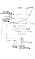
- FIG. 1 is a schematic configuration diagram of a front engine / rear drive hybrid vehicle according to a first embodiment of the present invention.
- FIG. 2 is a flowchart illustrating the idle control in the HEV traveling mode according to the first embodiment of the present invention.
- FIG. 3 is a diagram for explaining a method for taking over the F / B motor generator torque when the motor idle control is switched to the engine idle control.
- FIG. 4 is a time chart for explaining the idle control operation in the HEV travel mode according to the first embodiment of the present invention.
- FIG. 5 is a diagram for explaining a method for correcting the F / B engine torque according to the second embodiment of the present invention.
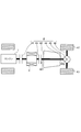
- FIG. 6 is a schematic configuration diagram of a front engine / rear drive hybrid vehicle according to another embodiment of the present invention.
- FIG. 7 is a schematic configuration diagram of a front engine / rear drive hybrid vehicle according to another embodiment of the present invention.
- FIG. 1 is a schematic configuration diagram of a front engine / rear drive type hybrid vehicle (hereinafter referred to as “FR hybrid vehicle”) according to the present embodiment.
- the FR hybrid vehicle includes an engine 1 and a motor generator 2 as a power source, a battery 3 as a power source, a drive system 4 including a plurality of components for transmitting the output of the power source to a rear wheel 47, and an engine 1. And a control system 5 including a plurality of controllers for controlling the components of the motor generator 2 and the drive system 4.
- Engine 1 is a gasoline engine.
- a diesel engine can also be used.
- the motor generator 2 is a synchronous motor generator in which a permanent magnet is embedded in a rotor and a stator coil is wound around a stator.
- the motor generator 2 has a function as an electric motor that rotates by receiving power supplied from the battery 3, and a function as a generator that generates an electromotive force at both ends of the stator coil when the rotor is rotated by an external force. Have.
- the battery 3 supplies electric power to various electric parts such as the motor generator 2 and stores the electric power generated by the motor generator 2.
- the drive system 4 of the FR hybrid vehicle includes a first clutch 41, an automatic transmission 42, a second clutch 43, a propeller shaft 44, a final deceleration differential device 45, and a drive shaft 46.
- the first clutch 41 is provided between the engine 1 and the motor generator 2.
- the first clutch 41 is a wet multi-plate clutch capable of continuously changing the torque capacity by controlling the oil flow rate and hydraulic pressure by the first solenoid valve 411.
- the first clutch 41 is controlled in three states, that is, an engaged state, a slip state (half-clutch state), and a released state by changing the torque capacity.
- the automatic transmission 42 is a stepped transmission with 7 forward speeds and 1 reverse speed.
- the automatic transmission 42 includes four sets of planetary gear mechanisms and a plurality of frictional engagement elements (three sets of multi-plate clutches, four sets) connected to a plurality of rotating elements constituting the planetary gear mechanism and changing their linkage state.
- the gear position is switched by adjusting the hydraulic pressure supplied to each frictional engagement element and changing the engagement / release state of each frictional engagement element.
- the second clutch 43 is a wet multi-plate clutch that can continuously change the torque capacity by controlling the oil flow rate and hydraulic pressure by the second solenoid valve 431.
- the second clutch 43 is controlled by changing the torque capacity into three states: an engaged state, a slip state (half-clutch state), and a released state.
- some of the plurality of frictional engagement elements included in the automatic transmission 42 are used as the second clutch 43.
- the propeller shaft 44 connects the output shaft of the automatic transmission 42 and the input shaft of the final deceleration differential 45.
- the final reduction gear differential 45 is a combination of the final reduction gear and the differential gear, and transmits the rotation to the left and right drive shafts 46 after decelerating the rotation of the propeller shaft 44. Further, when it is necessary to create a speed difference between the rotational speeds of the left and right drive shafts 46 such as during a curve run, the speed difference is automatically given to enable smooth running.
- Rear wheels 47 are attached to the front ends of the left and right drive shafts 46, respectively.
- the control system 5 of the FR hybrid vehicle includes an integrated controller 51, an engine controller 52, a motor controller 53, an inverter 54, a first clutch controller 55, a transmission controller 56, and a brake controller 57.
- Each controller is connected to a CAN (Controller Area Network) communication line 58 and can transmit and receive data to and from each other by CAN communication.
- CAN Controller Area Network
- the integrated controller 51 includes an accelerator stroke sensor 60, a vehicle speed sensor 61, an engine rotation sensor 62, a motor generator rotation sensor 63, a transmission input rotation sensor 64, a transmission output rotation sensor 65, an SOC (State Of Of Charge) sensor 66, wheels. Detection signals of various sensors for detecting the traveling state of the FR hybrid vehicle such as the speed sensor 67, the brake stroke sensor 68, and the acceleration sensor 69 are input.
- the accelerator stroke sensor 60 detects the amount of depression of the accelerator pedal (hereinafter referred to as “accelerator operation amount”) indicating the driver's required drive torque.
- the vehicle speed sensor 61 detects the traveling speed of the FR hybrid vehicle (hereinafter referred to as “vehicle speed”).
- the engine rotation sensor 62 detects the engine rotation speed.
- Motor generator rotation sensor 63 detects the motor generator rotation speed.
- the transmission input rotation sensor 64 detects the rotation speed of the input shaft 421 of the automatic transmission 42 (hereinafter referred to as “transmission input rotation speed”).
- the transmission output rotation sensor 65 detects the rotation speed of the output shaft 422 of the automatic transmission 42.
- the SOC sensor 66 detects the battery charge amount.
- the wheel speed sensor 67 detects the wheel speeds of the four wheels.
- the brake stroke sensor 68 detects the amount of depression of the brake pedal (hereinafter referred to as “brake operation amount”).
- the acceleration sensor 69 detects the longitudinal acceleration of the hybrid vehicle.
- the integrated controller 51 manages the energy consumption of the entire FR hybrid vehicle, and in order to drive the FR hybrid vehicle with the highest efficiency, based on the detection signals of various sensors inputted, the EV (Electric Vehicle) drive mode or HEV (HEV ( Hybrid Electric Vehicle)
- One of the travel modes is selected as the target travel mode, and a control command value to be output to each controller is calculated.
- a target engine torque, a target motor generator torque, a target first clutch torque capacity, a target second clutch torque capacity, a target gear position, a regeneration cooperative control command, and the like are calculated as control command values and output to each controller. .
- the EV travel mode is a travel mode in which the first clutch 41 is released and the FR hybrid vehicle is driven using only the motor generator 2 as a power source.
- the HEV traveling mode is a traveling mode in which the first clutch 41 is engaged and the FR hybrid vehicle is driven while including the engine 1 as a power source.
- the three traveling modes are an engine traveling mode, a motor assist traveling mode, and a power generation traveling mode. Is provided.
- the engine running mode is a mode for driving the FR hybrid vehicle using only the engine 1 as a power source.
- the motor assist travel mode is a mode in which the FR hybrid vehicle is driven by using the engine 1 and the motor generator 2 as power sources.
- the power generation traveling mode is a mode in which the FR hybrid vehicle is driven using only the engine 1 as a power source and the motor generator 2 functions as a generator.
- the target engine torque calculated by the integrated controller 51 is input to the engine controller 52 via the CAN communication line 58.
- the engine controller 52 controls the intake air amount (throttle valve opening), fuel injection amount, ignition timing, and the like of the engine 1 so that the engine torque becomes the target engine torque.
- the target motor generator torque calculated by the integrated controller 51 is input to the motor controller 53 via the CAN communication line 58.
- the motor controller 53 controls the inverter 54 so that the motor torque becomes the target motor generator torque.
- the inverter 54 is a current converter that mutually converts two types of electricity, DC and AC.
- the inverter 54 converts the direct current from the battery 3 into a three-phase alternating current having an arbitrary frequency so as to make the motor torque equal to the target motor generator torque, and supplies it to the motor generator 2.
- the motor generator 2 functions as a generator, the three-phase alternating current from the motor generator 2 is converted into direct current and supplied to the battery 3.
- the target first clutch torque capacity calculated by the integrated controller 51 is input to the first clutch controller 55 via the CAN communication line 58.
- the first clutch controller 55 controls the first solenoid valve 411 so that the torque capacity of the first clutch 41 becomes the target first clutch torque capacity.
- the target second clutch torque capacity and the target shift speed calculated by the integrated controller 51 are input to the transmission controller 56 via the CAN communication line 58.
- the transmission controller 56 controls the second solenoid valve 431 so that the torque capacity of the second clutch 43 becomes the target second clutch torque capacity. Further, the hydraulic pressure supplied to each friction engagement element of the automatic transmission 42 is controlled so that the gear position of the automatic transmission 42 becomes the target gear position.
- the regenerative cooperative control command from the integrated controller 51 is input to the brake controller 57. If the regenerative braking torque by the motor generator is insufficient for the required braking force calculated from the brake operation amount when the brake pedal is depressed, the brake controller 57 compensates for the deficiency with the friction braking torque by the brake. The regenerative cooperative brake control is performed based on the regenerative cooperative control command.
- the EV travel mode is basically selected, and the engine is stopped.
- the HEV driving mode is selected even when the vehicle is stopped in order to warm up the engine early and activate the catalyst.
- the engine may be started with the first clutch engaged. In this case, after the engine is started, idle operation is performed in the HEV travel mode in which the first clutch is engaged, and the engine speed is maintained at the idle speed by feedback control.
- idle control As a method of idle control at the time of this HEV traveling motor, while controlling the motor generator torque to a predetermined target generator torque, feedback control of the engine torque (intake air amount) is performed to maintain the engine rotational speed at the idle rotational speed.
- Idle control engine idle control
- idle control motor idle control
- motor idle control is performed in which feedback control is basically performed by a motor generator having excellent response and controllability.
- feedback control is basically performed by a motor generator having excellent response and controllability.
- an idling operation that is more stable than that during engine idle control can be performed, so that the ignition timing can be retarded as compared with that during engine idle control, and warm-up of the engine can be promoted.
- the engine idle control is performed only when it is difficult to perform the motor idle control, for example, when the battery SOC is extremely low.
- a motor generator feedback torque (hereinafter referred to as “F / B motor generator torque”) calculated based on the deviation between the actual engine rotational speed and the target idle rotational speed is input to the engine as a load.
- F / B motor generator torque a motor generator feedback torque
- FIG. 2 is a flowchart for explaining the idle control in the HEV traveling mode according to the present embodiment.
- step S1 the integrated controller 51 reads detection values of various sensors.
- step S2 the integrated controller 51 determines whether or not the motor idle control can be performed based on the battery SOC, the battery temperature, the input / output current of the battery, and the like. If it is determined that the motor idle control can be performed, the integrated controller 51 performs the process of step S2. On the other hand, if the integrated controller 51 determines that the motor idle control cannot be performed, the integrated controller 51 performs the process of step S3.
- step S3 the integrated controller 51 performs motor idle control.
- the engine rotation speed is maintained at the idle rotation speed by feedback controlling the motor generator torque while controlling the engine torque to the predetermined target engine torque. Further, the ignition timing is retarded from the basic ignition timing set during engine idle control.
- step S4 the integrated controller 51 determines whether or not the motor idle control is switched to the engine idle control.
- the integrated controller 51 performs the process of step S5 when the motor idle control is switched to the engine idle control. On the other hand, if the motor idle control is not switched to the engine idle control, the process of step S6 is performed.
- step S5 the integrated controller 51 performs transition control from motor idle control to engine idle control. Specifically, the F / B motor generator torque during the motor idle control is taken over as the F / B engine torque, and the process shifts to engine idle control.
- step S6 the integrated controller 51 performs engine idle control.
- engine idle control as described above, while controlling the motor generator torque to a predetermined target generator torque, feedback control is performed on the engine torque (intake air amount) to maintain the engine rotational speed at the idle rotational speed.
- FIG. 3 is a diagram for explaining a method for taking over the F / B motor generator torque when the motor idle control is switched to the engine idle control.
- the engine feedforward torque (hereinafter referred to as “F / F engine torque”) calculated based on the engine load, the engine water temperature, the ignition timing, and the like is referred to as F / B.
- F / F engine torque A value obtained by adding the engine torque is calculated as the target engine torque.
- the target intake air amount is calculated from the table of FIG. 3, and the opening degree of the throttle valve is controlled so as to be the target intake air amount.
- the relationship between the engine torque and the intake air amount will be described. As shown in FIG. 3, until the engine torque reaches a predetermined engine torque, the required intake air amount increases linearly as the engine torque increases. It will increase. However, when the engine torque exceeds a predetermined engine torque, a so-called non-sonic region is entered, and the required intake air amount increases nonlinearly as the engine torque increases.
- the intake air amount required to output the engine torque corresponding to the F / B motor generator torque is different between the sonic region and the non-sonic region. Then, the calculation is based on the sum of the intake air amounts calculated independently from the F / F engine torque and the F / B engine torque, and the sum of the F / F engine torque and the F / B engine torque. If the intake air amount is compared, the former intake air amount is reduced. That is, in the former case, even if the F / B motor generator torque is taken over as the F / B engine torque, the intake air amount necessary for outputting the engine torque corresponding to the F / B motor generator torque can be supplied. Disappear.
- the F / B motor generator torque when the F / B motor generator torque is taken over as the F / B engine torque, the F / F engine torque and the F / B motor generator torque taken over as the F / B engine torque are added to the engine torque. Based on this, a target intake air amount is calculated.
- the intake air amount is not insufficient. . Therefore, at the time of switching from the motor idle control to the engine idle control, the F / B motor generator torque can be reliably supplemented with the engine torque.
- FIG. 4 is a time chart for explaining the idle control operation in the HEV travel mode according to the present embodiment.
- motor idle control is performed until time t1.
- the engine torque is controlled to a predetermined target engine torque (FIG. 4C), and the motor generator torque is feedback controlled (FIG. 4B).
- the engine rotation speed is maintained at the idle rotation speed (FIG. 4A).
- the target motor generator torque during idle control is a negative value, and power generation by the motor generator 2 is performed.
- the intake air amount is feedforward controlled so that the engine torque becomes a predetermined target engine torque, but the actual engine torque is smaller than the target engine torque.
- the idle rotation speed is maintained by the torque being larger than the target motor generator torque (negative torque is small).
- the F / B motor generator torque is a positive value.
- the F / B motor generator torque during the motor idle control is taken over as the F / B engine torque.
- the intake air amount corresponding to the F / B motor generator torque is added at the time t1 (FIG. 4D), and therefore, a temporary drop in engine speed and a sudden increase at the time of switching are suppressed.
- FIG. 4A the intake air amount is added (increased) because the F / B motor generator torque has a positive value.
- the F / B motor generator torque has a negative value, the intake air amount is increased. The amount of air is reduced, and a temporary increase in engine speed at the time of switching can be suppressed.
- the ignition timing is gradually advanced to the ignition timing (basic ignition timing) for engine idle control.
- engine idle control is performed.
- the motor generator torque is controlled to a predetermined target generator torque (FIG. 4B), and the engine torque (intake air amount) is feedback controlled (FIG. 4D).
- the engine rotation speed is maintained at the idle rotation speed (FIG. 4A).
- the F / B motor generator torque during the motor idle control is set as the F / B engine torque.
- engine idle control will be implemented. That is, the motor generator load torque (F / B motor generator torque) input to the engine to maintain the engine rotation speed at the idle rotation speed during motor idle control is added to the engine output torque. It was decided to shift to engine idle control.
- the F / B motor generator torque inherited as the F / B engine torque is converted into the target intake air amount
- the F / B motor generator torque is added to the F / F engine torque. Is converted into the target intake air amount as the target engine torque.
- the F / F engine torque is calculated in consideration of the ignition timing in addition to the engine load and the engine water temperature, but the influence of the ignition timing is taken into consideration for the inherited F / B engine torque. I did not.
- the F / B motor generator torque is taken over as the F / B engine torque
- the F / B engine torque is corrected according to the retard amount of the ignition timing.
- FIG. 5 is a diagram illustrating a method for correcting the F / B engine torque according to the present embodiment.
- the conversion is performed.
- the intake air amount thus obtained is the intake air amount necessary for outputting the F / B engine torque in a state where the ignition timing is set to the basic ignition timing that is normally set during engine idle control.
- the F / B engine torque taken over is increased and corrected according to the retard amount of the ignition timing, and the corrected F / B engine torque is used as the intake air amount. I decided to convert to
- the second clutch 43 of the FR hybrid vehicle may be provided separately between the motor generator 2 and the automatic transmission 42 as shown in FIG. 6, or the automatic transmission 42 as shown in FIG. You may provide separately behind.
- the second clutch 43 may be provided between the motor generator 2 and the drive wheels.
- a stepped transmission of 7 forward speeds and 1 reverse speed is used as the automatic transmission 42.
- the number of shift speeds is not limited to this, and a continuously variable transmission is used. You can also
Abstract
Description
図1は、本実施形態によるフロントエンジン・リアドライブ方式のハイブリッド車両(以下「FRハイブリッド車両」という。)の概略構成図である。 (First embodiment)
FIG. 1 is a schematic configuration diagram of a front engine / rear drive type hybrid vehicle (hereinafter referred to as “FR hybrid vehicle”) according to the present embodiment.
次に、図5を参照して本発明の第2実施形態について説明する。本実施形態は、点火時期の遅角量に応じて、引き継いだF/Bエンジントルクを補正する点で第1実施形態と相違する。以下、その相違点を中心に説明する。なお、以下に示す各実施形態では前述した第1実施形態と同様の機能を果たす部分には、同一の符号を用いて重複する説明を適宜省略する。 (Second Embodiment)
Next, a second embodiment of the present invention will be described with reference to FIG. The present embodiment is different from the first embodiment in that the inherited F / B engine torque is corrected according to the retard amount of the ignition timing. Hereinafter, the difference will be mainly described. In each of the following embodiments, the same reference numerals are used for portions that perform the same functions as those of the first embodiment described above, and repeated descriptions are omitted as appropriate.
Claims (6)
- 動力源としてエンジン及びモータジェネレータを備えるハイブリッド車両の制御装置であって、
前記エンジンと前記モータジェネレータとを連結した状態でエンジン回転速度をアイドル回転速度に維持するアイドル運転時に、前記エンジンによってエンジン回転速度をアイドル回転速度に維持するエンジンアイドル制御を実施するエンジンアイドル手段と、
前記アイドル運転時に、前記モータジェネレータによってエンジン回転速度をアイドル回転速度に維持するモータアイドル制御を実施するモータアイドル手段と、
ハイブリッド車両の運転状態に応じて、前記エンジンアイドル制御を実施するか、前記モータアイドル制御を実施するかを切り替える切替手段と、
前記アイドル運転時に前記モータアイドル制御から前記エンジンアイドル制御に切り替わったときに、前記モータアイドル制御中にエンジン回転速度をアイドル回転速度に維持するために前記エンジンに入力されていた前記モータジェネレータの負荷トルク分を、前記エンジンの出力トルクに付加して前記エンジンアイドル制御に移行するアイドル制御移行手段と、
を備えるハイブリッド車両の制御装置。 A hybrid vehicle control device including an engine and a motor generator as a power source,
Engine idle means for performing engine idle control for maintaining the engine rotational speed at the idle rotational speed by the engine during idle operation in which the engine rotational speed is maintained at the idle rotational speed in a state where the engine and the motor generator are coupled;
Motor idle means for performing motor idle control for maintaining the engine rotational speed at the idle rotational speed by the motor generator during the idle operation;
Switching means for switching whether to implement the engine idle control or the motor idle control according to the driving state of the hybrid vehicle;
The load torque of the motor generator that has been input to the engine to maintain the engine rotation speed at the idle rotation speed during the motor idle control when the motor idle control is switched to the engine idle control during the idle operation. An idle control transition means for adding the minute to the output torque of the engine and transitioning to the engine idle control;
A control apparatus for a hybrid vehicle comprising: - 前記エンジンアイドル手段は、
エンジン回転速度がアイドル回転速度となるように、前記エンジンの出力トルクのフィードバック補正量を設定するフォードバック制御を実施し、
前記モータアイドル手段は、
エンジン回転速度がアイドル回転速度となるように、前記モータジェネレータの出力トルクのフィードバック補正量を設定するフィードバック制御を実施し、
前記アイドル制御移行手段は、
前記モータアイドル制御中の前記モータジェネレータの出力トルクのフィードバック補正量を、前記エンジンの出力トルクのフィードバック補正量として引き継ぐことで、前記モータジェネレータの負荷トルク分を前記エンジンの出力トルクに付加する、
請求項1に記載のハイブリッド車両の制御装置。 The engine idle means is
Fordback control for setting a feedback correction amount of the output torque of the engine so that the engine rotation speed becomes the idle rotation speed,
The motor idle means is
Implement feedback control to set the feedback correction amount of the output torque of the motor generator so that the engine rotation speed becomes the idle rotation speed,
The idle control transition means includes
The amount of load torque of the motor generator is added to the engine output torque by taking over the amount of feedback correction of the output torque of the motor generator during the motor idle control as the feedback correction amount of the engine output torque.
The hybrid vehicle control device according to claim 1. - 前記アイドル制御移行手段は、
前記エンジンの吸入空気量を、前記モータジェネレータの負荷トルク分に相当する出力トルクを前記エンジンが出力するために必要な吸入空気量だけ増量させて前記エンジンアイドル制御に移行する、
請求項1又は請求項2に記載のハイブリッド車両の制御装置。 The idle control transition means includes
Increasing the intake air amount of the engine by an intake air amount necessary for the engine to output an output torque corresponding to the load torque of the motor generator, and then shifting to the engine idle control.
The control apparatus of the hybrid vehicle of Claim 1 or Claim 2. - 前記アイドル制御移行手段は、
非ソニック領域を考慮して、増量させる吸入空気量を算出する、
請求項3に記載のハイブリッド車両の制御装置。 The idle control transition means includes
Calculate the amount of intake air to be increased in consideration of the non-sonic region,
The control apparatus of the hybrid vehicle of Claim 3. - 前記モータアイドル制御中は、前記エンジンアイドル制御中よりも前記エンジンの点火時期を遅角させる点火時期制御手段を備え、
前記アイドル制御移行手段は、
点火時期の遅角量に基づいて、増量させる吸入空気量を補正する、
請求項3又は請求項4に記載のハイブリッド車両の制御装置。 During the motor idle control, the ignition timing control means for retarding the ignition timing of the engine than during the engine idle control,
The idle control transition means includes
Correct the amount of intake air to be increased based on the retard amount of the ignition timing,
The control apparatus of the hybrid vehicle of Claim 3 or Claim 4. - 動力源としてエンジン及びモータジェネレータを備え、前記エンジンと前記モータジェネレータとを連結した状態でエンジン回転速度をアイドル回転速度に維持するアイドル運転を行うハイブリッド車両の制御方法であって、
前記アイドル運転時に、ハイブリッド車両の運転状態に応じて、前記モータジェネレータによってエンジン回転速度をアイドル回転速度に維持するモータアイドル制御から、前記エンジンによってエンジン回転速度をアイドル回転速度に維持するエンジンアイドル制御に切り替える切り替え工程と、
前記モータアイドル制御から前記エンジンアイドル制御に切り替えるときは、前記モータアイドル制御中にエンジン回転速度をアイドル回転速度に維持するために前記エンジンに入力されていた前記モータジェネレータの負荷トルク分を、前記エンジンの出力トルクに付加して前記エンジンアイドル制御に移行する移行工程と、
を備えるハイブリッド車両の制御方法。 A control method for a hybrid vehicle comprising an engine and a motor generator as a power source, and performing an idle operation for maintaining the engine rotation speed at an idle rotation speed in a state where the engine and the motor generator are coupled,
During the idle operation, the motor idle control for maintaining the engine rotation speed at the idle rotation speed by the motor generator is changed from the motor idle control for maintaining the engine rotation speed to the idle rotation speed by the engine according to the driving state of the hybrid vehicle. A switching process for switching;
When switching from the motor idle control to the engine idle control, the load torque of the motor generator input to the engine in order to maintain the engine rotational speed at the idle rotational speed during the motor idle control, A transition step of shifting to the engine idle control in addition to the output torque of
A control method for a hybrid vehicle comprising:
Priority Applications (4)
| Application Number | Priority Date | Filing Date | Title |
|---|---|---|---|
| EP13815958.7A EP2873576B1 (en) | 2012-07-13 | 2013-05-01 | Hybrid vehicle control device and hybrid vehicle control method |
| CN201380037451.6A CN104470778B (en) | 2012-07-13 | 2013-05-01 | The control setup of motor vehicle driven by mixed power |
| JP2014524676A JP6056858B2 (en) | 2012-07-13 | 2013-05-01 | Hybrid vehicle control apparatus and hybrid vehicle control method |
| US14/414,222 US9216735B2 (en) | 2012-07-13 | 2013-05-01 | Hybrid vehicle control device and hybrid vehicle control method |
Applications Claiming Priority (2)
| Application Number | Priority Date | Filing Date | Title |
|---|---|---|---|
| JP2012-157589 | 2012-07-13 | ||
| JP2012157589 | 2012-07-13 |
Publications (1)
| Publication Number | Publication Date |
|---|---|
| WO2014010298A1 true WO2014010298A1 (en) | 2014-01-16 |
Family
ID=49915773
Family Applications (1)
| Application Number | Title | Priority Date | Filing Date |
|---|---|---|---|
| PCT/JP2013/062731 WO2014010298A1 (en) | 2012-07-13 | 2013-05-01 | Device for controlling hybrid vehicle and method for controlling hybrid vehicle |
Country Status (5)
| Country | Link |
|---|---|
| US (1) | US9216735B2 (en) |
| EP (1) | EP2873576B1 (en) |
| JP (1) | JP6056858B2 (en) |
| CN (1) | CN104470778B (en) |
| WO (1) | WO2014010298A1 (en) |
Cited By (1)
| Publication number | Priority date | Publication date | Assignee | Title |
|---|---|---|---|---|
| JP2021133692A (en) * | 2020-02-21 | 2021-09-13 | トヨタ自動車株式会社 | Vehicular rotation speed control apparatus |
Families Citing this family (6)
| Publication number | Priority date | Publication date | Assignee | Title |
|---|---|---|---|---|
| DE112014006571B4 (en) * | 2014-04-10 | 2021-08-05 | Mitsubishi Electric Corporation | Engine start control device |
| JP6399046B2 (en) * | 2016-07-04 | 2018-10-03 | トヨタ自動車株式会社 | Automobile |
| US20200215930A1 (en) * | 2017-08-10 | 2020-07-09 | Sumitomo Electric Industries, Ltd. | Control apparatus, control method, and computer program |
| DE102018212358A1 (en) * | 2018-07-25 | 2020-01-30 | Continental Automotive Gmbh | Method for operating an idle control device, idle control device and motor vehicle |
| JP7373446B2 (en) * | 2020-03-31 | 2023-11-02 | 本田技研工業株式会社 | Hybrid vehicle and its control method |
| CN112455594B (en) * | 2020-11-30 | 2022-04-15 | 广东高标电子科技有限公司 | Idling control method for small electric vehicle and small electric vehicle |
Citations (6)
| Publication number | Priority date | Publication date | Assignee | Title |
|---|---|---|---|---|
| JPH09158961A (en) * | 1995-12-08 | 1997-06-17 | Aisin Aw Co Ltd | Control device of driving gear for vehicle |
| JP2002357147A (en) * | 2001-03-30 | 2002-12-13 | Nissan Motor Co Ltd | Air-fuel ratio controller for engine |
| JP2003041965A (en) | 2001-05-03 | 2003-02-13 | Ford Motor Co | Method and system for controlling engine idle speed in hybrid electric vehicle |
| JP2006057590A (en) * | 2004-08-23 | 2006-03-02 | Toyota Motor Corp | Internal combustion engine control system, automobile mounted therewith, and internal combustion engine control method |
| JP2011098695A (en) * | 2009-11-09 | 2011-05-19 | Toyota Motor Corp | Control device for hybrid vehicle |
| JP2012030626A (en) * | 2010-07-28 | 2012-02-16 | Toyota Motor Corp | Control apparatus of vehicle drive device |
Family Cites Families (8)
| Publication number | Priority date | Publication date | Assignee | Title |
|---|---|---|---|---|
| JPH0849582A (en) * | 1994-08-10 | 1996-02-20 | Nissan Motor Co Ltd | Intake quantity control device for lean-burn engine |
| DE19704153C2 (en) * | 1997-02-04 | 2000-10-19 | Isad Electronic Sys Gmbh & Co | Drive system, in particular for a motor vehicle and method for counteracting a change in the idle speed in a drive system |
| JP3589143B2 (en) * | 2000-03-21 | 2004-11-17 | 日産自動車株式会社 | Vehicle idle stop / restart control device |
| US9002550B2 (en) * | 2007-07-02 | 2015-04-07 | GM Global Technology Operations LLC | Use of torque model at virtual engine conditions |
| US7691027B2 (en) * | 2007-11-29 | 2010-04-06 | Ford Global Technologies, Llc | Idle speed control of a hybrid electric vehicle |
| US7762232B2 (en) * | 2008-11-06 | 2010-07-27 | Ford Global Technologies, Llc | Engine and exhaust heating for hybrid vehicle |
| WO2010137100A1 (en) * | 2009-05-25 | 2010-12-02 | トヨタ自動車株式会社 | Hybrid automobile and method for controlling same |
| JP5699520B2 (en) * | 2010-10-18 | 2015-04-15 | 日産自動車株式会社 | Vehicle idle control device |
-
2013
- 2013-05-01 CN CN201380037451.6A patent/CN104470778B/en active Active
- 2013-05-01 WO PCT/JP2013/062731 patent/WO2014010298A1/en active Application Filing
- 2013-05-01 EP EP13815958.7A patent/EP2873576B1/en active Active
- 2013-05-01 US US14/414,222 patent/US9216735B2/en active Active
- 2013-05-01 JP JP2014524676A patent/JP6056858B2/en active Active
Patent Citations (6)
| Publication number | Priority date | Publication date | Assignee | Title |
|---|---|---|---|---|
| JPH09158961A (en) * | 1995-12-08 | 1997-06-17 | Aisin Aw Co Ltd | Control device of driving gear for vehicle |
| JP2002357147A (en) * | 2001-03-30 | 2002-12-13 | Nissan Motor Co Ltd | Air-fuel ratio controller for engine |
| JP2003041965A (en) | 2001-05-03 | 2003-02-13 | Ford Motor Co | Method and system for controlling engine idle speed in hybrid electric vehicle |
| JP2006057590A (en) * | 2004-08-23 | 2006-03-02 | Toyota Motor Corp | Internal combustion engine control system, automobile mounted therewith, and internal combustion engine control method |
| JP2011098695A (en) * | 2009-11-09 | 2011-05-19 | Toyota Motor Corp | Control device for hybrid vehicle |
| JP2012030626A (en) * | 2010-07-28 | 2012-02-16 | Toyota Motor Corp | Control apparatus of vehicle drive device |
Non-Patent Citations (1)
| Title |
|---|
| See also references of EP2873576A4 |
Cited By (2)
| Publication number | Priority date | Publication date | Assignee | Title |
|---|---|---|---|---|
| JP2021133692A (en) * | 2020-02-21 | 2021-09-13 | トヨタ自動車株式会社 | Vehicular rotation speed control apparatus |
| JP7322746B2 (en) | 2020-02-21 | 2023-08-08 | トヨタ自動車株式会社 | Vehicle speed control device |
Also Published As
| Publication number | Publication date |
|---|---|
| US20150166043A1 (en) | 2015-06-18 |
| EP2873576A4 (en) | 2015-12-23 |
| EP2873576A1 (en) | 2015-05-20 |
| US9216735B2 (en) | 2015-12-22 |
| CN104470778B (en) | 2016-04-20 |
| EP2873576B1 (en) | 2018-04-11 |
| JPWO2014010298A1 (en) | 2016-06-20 |
| JP6056858B2 (en) | 2017-01-11 |
| CN104470778A (en) | 2015-03-25 |
Similar Documents
| Publication | Publication Date | Title |
|---|---|---|
| JP5371200B2 (en) | An engine start control device for a hybrid vehicle and an engine start control method for a hybrid vehicle. | |
| JP5401999B2 (en) | Vehicle traction control device | |
| JP5141305B2 (en) | Control device for hybrid vehicle | |
| JP5454698B2 (en) | Control device for hybrid vehicle | |
| JP6056858B2 (en) | Hybrid vehicle control apparatus and hybrid vehicle control method | |
| JP4862624B2 (en) | Control device for hybrid vehicle | |
| EP2743149A1 (en) | Hybrid vehicle control unit | |
| JP5678575B2 (en) | Control device for hybrid vehicle | |
| JP2011020542A (en) | Electric vehicle control device | |
| JP5918464B2 (en) | Control device for hybrid vehicle | |
| JP2010215097A (en) | Clutch control device for hybrid car | |
| JP2010143418A (en) | Starting controller for hybrid vehicle | |
| JP5029275B2 (en) | Driving force control device | |
| JP2012131497A (en) | Engine start control device of hybrid vehicle and method of controlling engine start of hybrid vehicle | |
| JP2010149714A (en) | Control device of hybrid vehicle | |
| JP6492908B2 (en) | Control device for hybrid vehicle | |
| WO2014027501A1 (en) | Vehicle control device and vehicle control method | |
| JP5696430B2 (en) | Vehicle control device | |
| JP5251958B2 (en) | Control device for hybrid vehicle | |
| JP2012092975A (en) | Automatic transmission | |
| JP5550524B2 (en) | Automatic transmission | |
| JP5223378B2 (en) | Vehicle start control device | |
| JP5527159B2 (en) | Control device for hybrid vehicle | |
| JP5590204B2 (en) | Vehicle traction control device | |
| JP2012092939A5 (en) |
Legal Events
| Date | Code | Title | Description |
|---|---|---|---|
| WWE | Wipo information: entry into national phase |
Ref document number: 201380037451.6 Country of ref document: CN |
|
| 121 | Ep: the epo has been informed by wipo that ep was designated in this application |
Ref document number: 13815958 Country of ref document: EP Kind code of ref document: A1 |
|
| ENP | Entry into the national phase |
Ref document number: 2014524676 Country of ref document: JP Kind code of ref document: A |
|
| WWE | Wipo information: entry into national phase |
Ref document number: 14414222 Country of ref document: US |
|
| NENP | Non-entry into the national phase |
Ref country code: DE |
|
| WWE | Wipo information: entry into national phase |
Ref document number: 2013815958 Country of ref document: EP |