WO2014010184A1 - 呈色測定装置および方法 - Google Patents
呈色測定装置および方法 Download PDFInfo
- Publication number
- WO2014010184A1 WO2014010184A1 PCT/JP2013/003921 JP2013003921W WO2014010184A1 WO 2014010184 A1 WO2014010184 A1 WO 2014010184A1 JP 2013003921 W JP2013003921 W JP 2013003921W WO 2014010184 A1 WO2014010184 A1 WO 2014010184A1
- Authority
- WO
- WIPO (PCT)
- Prior art keywords
- test
- cleaning
- determination process
- test substance
- area
- Prior art date
- Legal status (The legal status is an assumption and is not a legal conclusion. Google has not performed a legal analysis and makes no representation as to the accuracy of the status listed.)
- Ceased
Links
Images





Classifications
-
- G—PHYSICS
- G01—MEASURING; TESTING
- G01N—INVESTIGATING OR ANALYSING MATERIALS BY DETERMINING THEIR CHEMICAL OR PHYSICAL PROPERTIES
- G01N21/00—Investigating or analysing materials by the use of optical means, i.e. using sub-millimetre waves, infrared, visible or ultraviolet light
- G01N21/62—Systems in which the material investigated is excited whereby it emits light or causes a change in wavelength of the incident light
- G01N21/63—Systems in which the material investigated is excited whereby it emits light or causes a change in wavelength of the incident light optically excited
- G01N21/64—Fluorescence; Phosphorescence
- G01N21/6428—Measuring fluorescence of fluorescent products of reactions or of fluorochrome labelled reactive substances, e.g. measuring quenching effects, using measuring "optrodes"
-
- G—PHYSICS
- G01—MEASURING; TESTING
- G01N—INVESTIGATING OR ANALYSING MATERIALS BY DETERMINING THEIR CHEMICAL OR PHYSICAL PROPERTIES
- G01N33/00—Investigating or analysing materials by specific methods not covered by groups G01N1/00 - G01N31/00
- G01N33/48—Biological material, e.g. blood, urine; Haemocytometers
- G01N33/50—Chemical analysis of biological material, e.g. blood, urine; Testing involving biospecific ligand binding methods; Immunological testing
- G01N33/53—Immunoassay; Biospecific binding assay; Materials therefor
- G01N33/543—Immunoassay; Biospecific binding assay; Materials therefor with an insoluble carrier for immobilising immunochemicals
Definitions
- the present invention relates to a color measuring device and method for quantitatively or qualitatively measuring a test substance in a sample solution.
- a device that sends a sample solution that may contain a test substance to test specimens for in-vitro diagnostics, poisons, etc., to a test piece, and uses a immunochromatographic method to test the test substance simply and quickly Have been developed (see, for example, Patent Document 1).
- a labeled label that specifically binds to a test substance on an insoluble carrier composed of a porous body in which a first antibody that specifically binds to a test substance (eg, antigen) is immobilized in a specific region (test line).
- a specimen solution in which a specimen in which a test substance may exist in two antibodies is mixed is developed.
- test line is colored or colored to become colored.
- quantitative or qualitative (negative / positive) measurement is performed as to whether or not the test substance is present in the sample solution.
- the cleaning solution is developed on the test line and its surrounding area (background) to remove the label in the background, reducing the noise component and improving the S / N, thereby improving the measurement reliability.
- Proposals have been made (see, for example, Patent Document 2).
- the method of improving the S / N ratio by developing the cleaning solution improves the reliability of the measurement, but has a problem that it takes time for the measurement because it needs to go through a cleaning step before each measurement.
- an object of the present invention is to provide a color measurement device and method capable of achieving both measurement reliability and measurement time reduction.
- the color measurement apparatus of the present invention excites the test area of a test piece including a light source that emits excitation light that excites a fluorescent label and an insoluble carrier in which a test area that reacts with a test substance in a sample solution is formed. Judgment of detecting the fluorescence emission state of the fluorescent label captured in the test area via the test substance in the irradiated state and determining the presence or absence of the test substance in the sample solution based on the detection result Determination means for performing processing, cleaning liquid supply means for supplying a cleaning liquid for cleaning the test area and its surrounding area to the test piece, and after the sample solution is supplied to the test piece, the determination process is performed before cleaning. When the test substance is detected, the determination process is terminated, and when the test substance is not detected, the determination unit and the cleaning liquid supply unit are set so that the determination process is performed again after cleaning. Control means to control And said that there were pictures.
- the determination means detects the fluorescence emission state of the test area and the surrounding area, and when the difference between the detected values exceeds a predetermined threshold, the test substance is detected in the test piece.
- a predetermined threshold it is preferable to set the threshold value in the determination process after cleaning to a value larger than the threshold value in the determination process before cleaning.
- the fluorescent label is preferably semiconductor nanoparticles.
- the color measurement method of the present invention excites the test area of a test piece including a light source that emits excitation light for exciting a fluorescent label and an insoluble carrier in which a test area that reacts with a test substance in a sample solution is formed. Judgment of detecting the fluorescence emission state of the fluorescent label captured in the test area via the test substance in the irradiated state and determining the presence or absence of the test substance in the sample solution based on the detection result
- a color measurement method in a color measurement device comprising a determination means for performing processing, and a cleaning liquid supply means for supplying a cleaning liquid for cleaning the test area and its peripheral area to the test piece, After the sample solution is supplied, the determination process is performed before the cleaning, and when the test substance is detected, the determination process is terminated, and when the test substance is not detected, the cleaning process is performed. To perform the determination process again. And butterflies.
- the determination means detects the fluorescence emission state of the test area and the surrounding area, and when the difference between the detected values exceeds a predetermined threshold, the test substance is detected in the test piece.
- a predetermined threshold it is preferable to set the threshold value in the determination process after cleaning to a value larger than the threshold value in the determination process before cleaning.
- the test piece may be anything as long as the test region is in a fluorescence emission state due to the presence of the test substance. It may be a thing.
- the pattern shape of the test region is not limited, and may be formed in a line shape, for example, or may have a predetermined pattern.
- the test substance is determined before or after the cleaning step of supplying the test solution with a cleaning liquid for cleaning the test area and the surrounding area. If the test substance is detected, the determination process is terminated. If the test substance is not detected, the determination process is performed again after washing, and only when the test substance is not detected. Since cleaning is performed, it is possible to achieve both measurement reliability and measurement time reduction.
- the determination means detects the fluorescence emission state of the test area and the surrounding area, and determines that the test substance is present in the test piece when the difference between the detected values exceeds a predetermined threshold value.
- the higher the threshold value the lower the possibility of false detection and the better the detection accuracy, but at the same time the possibility of detection omission increases.
- the color measurement device and method of the present invention perform cleaning. Therefore, the detection accuracy in the determination process after cleaning can be improved by setting the threshold value in the determination process after cleaning to a value larger than the threshold value in the determination process before cleaning. it can.
- the fluorescent label is a semiconductor nanoparticle, high fluorescence emission intensity can be obtained.
- the wavelength of the excitation light and the wavelength of the fluorescence can be greatly separated. With such a configuration, the fluorescence emission and the excitation light can be easily distinguished, so that the detection accuracy can be further improved. .
- FIG. 1 is a schematic diagram showing a preferred embodiment of the color measurement device of the present invention
- FIG. 2 is a schematic diagram showing an example of a test piece used in the color measurement device of the present invention
- FIG. 3 is a color measurement of the present invention
- 4 is a schematic diagram showing an example of a test piece used in the apparatus
- FIG. 4 is a block diagram showing a preferred embodiment of the color measurement device of the present invention
- FIG. 5 is a schematic diagram showing an example of the sample processing means of FIG.
- the color measurement device 1 reads a test piece 10 for detecting a test substance using, for example, an immunochromatography technique, and includes a housing 2, a device insertion port 3, Information output means 4 and the like are provided. Then, the test piece on which the sample solution is spotted is inserted into the device insertion port 3, the color reaction generated in the test piece 10 is optically read, and the read result is output to the information input / output means 4.
- the information input / output means 4 is an operation panel composed of, for example, a liquid crystal touch panel, and a user can input basic settings for measurement via the operation panel.
- the test piece 10 is a device for performing a qualitative (negative / positive) test of a test substance using an immunochromatography method, and the test substance (predetermined antigen) Is labeled so as to be visible.
- the test piece 10 is spotted with a sample solution in which a sample that may contain a test substance and a labeled antibody that binds to the test substance (an antibody labeled with a fluorescent label) are mixed.
- the fluorescent label Although there is no particular limitation on the fluorescent label, if the fluorescent label is a semiconductor nanoparticle, high fluorescence emission intensity can be obtained. In addition, if the fluorescent label is a semiconductor nanoparticle, the wavelength of the excitation light and the wavelength of the fluorescence can be greatly separated. With such a configuration, it is easy to distinguish between the fluorescence emission and the excitation light. It becomes possible to judge the test result more accurately.
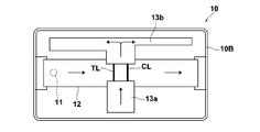
- the test piece 10 has an upper case 10A, a lower case 10B, and an insoluble carrier 12, and the insoluble carrier 12 is accommodated in the upper case 10A and the lower case 10B.
- the upper case 10A is formed with a through hole 11 for spotting the sample solution on the insoluble carrier 12 from the outside, a not-shown through hole for spotting a cleaning liquid on a later-described cleaning layer 13a, and the like.
- an insoluble carrier 12 is fixed to the lower case 10B, and an observation window 10Z for observing quantitative or qualitative measurement of a test substance is formed.
- information storage means 15 such as character information, bar code, IC tag, etc., which records identification information (name, etc.) of the sample and time information necessary for the reaction, is provided on the surface of the lower case 10B.
- the insoluble carrier 12 is made of an absorbent such as cellulose filter paper, glass fiber, polyurethane, etc., and the spotted sample solution flows in a certain direction by capillary action.
- a test region TL and a control region CL are formed in the insoluble carrier 12.
- the test region TL includes a first antibody having specificity for a test substance (antibody) fixed in a line (test line), and the first antibody-test substance is determined by the presence of the test substance.
- a conjugate of labeled antibody is formed and colored in a line;
- a reference antigen (or antibody) that reacts with the labeled antibody is fixed, and reacts with the labeled antibody in the sample solution and is colored in a line. Accordingly, by confirming the coloration state (fluorescence emission state) of the control region CL, it can be determined whether or not the sample solution has passed over the test region TL and the control region CL.
- the test piece 10 is a cleaning solution for cleaning the test region TL and the control region CL so as to sandwich the test region TL and the control region CL in the vertical direction in FIG. 3 (a direction substantially orthogonal to the flow path of the sample solution).
- the cleaning layers 13a and 13b forming the flow paths are provided.
- the cleaning layers 13a and 13b are made of the same material as the insoluble carrier 12, and the cleaning liquid flows in a region where the cleaning layers 13a and 13b and the insoluble carrier 12 are connected. Therefore, in FIG. 3, the cleaning liquid flows in the peripheral area including the test area TL and the control area CL.
- the cleaning liquid When the cleaning liquid is supplied from the specimen processing means 20 to the cleaning layer 13a, the cleaning liquid flows from the cleaning layer 13a to the cleaning layer 13b side by capillary action, and the test region TL and the control region CL existing between the cleaning layers 13a and 13b. The cleaning liquid flows through As a result, the labeled antibody that did not form an immune complex on the test region TL and the control region CL is removed.
- the color measurement device 1 is based on the specimen processing means (cleaning liquid supply means) 20, the reading means 21 for detecting the fluorescence emission state of the test area, and the detection result by the reading means 21.
- Determination means 22 for performing determination processing for determining the presence or absence of the test substance in the test piece, a light source 25 for irradiating excitation light L for exciting the fluorescent label, and a control means 30 for controlling them.
- the determination means in the claims comprises a reading means 21 and a determination means 22.
- the specimen processing means 20 supplies various solutions necessary for the specimen spotting process and cleaning process to the test piece 10.
- the sample processing means 20 shown in FIG. 5 has a function of automatically spotting the sample solution and the cleaning liquid on the test piece 10, and the test piece 10 and the sample are previously applied to the color measuring device 1.
- the sample processing means 20 attaches the nozzle tip NC to the nozzle holding unit 20a, extracts the sample solution from the sample container, and dispenses it into the test piece 10.
- the specimen processing means 20 extracts the cleaning liquid from the cleaning container and dispenses it into the test piece 10. Therefore, the sample processing unit 20 functions as a cleaning liquid supply unit.
- the reading unit 21 may read a gray scale value as a gray value, read each RGB component value as a gray value, or a predetermined color (wavelength component) such as fluorescence. ) May be read as a gray value.
- the reading means 21 is not limited to the image sensor, and may be a light receiving element that receives reflected light or fluorescence generated from the observation window 10Z.
- the determination means 22 is for determining the presence or absence of a test substance from the gray values of the test area TL and the control area CL read by the reading means 21. Specifically, the determination unit 22 determines whether or not the sample solution has been normally developed on the insoluble carrier 12 from the gray value of the control region CL. The determination means 22 determines the presence / absence of the test substance based on whether or not the difference between the gray values of the test region TL and the surrounding region BR exceeds a predetermined threshold value. Then, the determination result by the determination unit 22 is output from the information output unit 4.
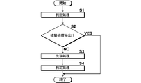
- FIG. 6 is a flowchart showing a preferred embodiment of the color measurement method of the present invention
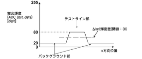
- FIG. 7 is a graph showing an example of the detection result of the fluorescence emission state before washing
- FIG. 8 is the detection result of the fluorescence emission state after washing. It is a graph which shows an example. Note that the processing here is performed by the control unit 30 by integrally controlling the sample processing unit (cleaning liquid supply unit) 20, the reading unit 21, the determination unit 22, the light source 25, and the like.
- test piece 10 and the sample container are loaded in the color measurement device 1, and the sample solution is spotted on the test piece 10 by the sample processing means 20.
- step S1 excitation light L is irradiated around the test region TL and the control region CL, and the presence / absence of the test substance is determined (step S1).
- the presence / absence of the test substance is determined based on whether or not the difference between the gray values of the test region TL and the surrounding region BR exceeds a predetermined threshold (10 in the present embodiment). To do. If the test substance is detected in step S1, the process is terminated as it is (step S2).
- step S2 If the test substance is not detected in step S1, the process is shifted (step S2), and then the cleaning process is performed (step S3). By this washing treatment, the labeled antibody that did not form an immune complex on the test region TL and the control region CL is removed.
- the determination process for the presence or absence of the test substance is performed again (step S4).
- a predetermined threshold as in the present embodiment.
- the higher the threshold value the lower the possibility of false detection and the higher the detection accuracy, but at the same time, the possibility of detection omission increases.
- the S / N can be improved by washing as described above. Therefore, the detection accuracy in the determination process after cleaning can be improved by setting the threshold value in the determination process after cleaning to a value larger than the threshold value in the determination process before cleaning.
- threshold value after cleaning than the threshold value before cleaning may be appropriately set in consideration of the configuration of the apparatus, the type of fluorescent label, the amount of noise reduced by cleaning, and the like. If it is at least about 3 times larger, the desired effect can be obtained.
- a threshold value (30 in the present embodiment) that is three times the threshold value before cleaning is set, and the difference between the gray values of the test area TL and its peripheral area BR is determined.
- the presence or absence of the test substance is determined based on whether or not the threshold value is exceeded, and the process is terminated.
Landscapes
- Health & Medical Sciences (AREA)
- Immunology (AREA)
- Life Sciences & Earth Sciences (AREA)
- Chemical & Material Sciences (AREA)
- Physics & Mathematics (AREA)
- Engineering & Computer Science (AREA)
- Urology & Nephrology (AREA)
- Molecular Biology (AREA)
- Analytical Chemistry (AREA)
- Biochemistry (AREA)
- General Health & Medical Sciences (AREA)
- General Physics & Mathematics (AREA)
- Pathology (AREA)
- Hematology (AREA)
- Biomedical Technology (AREA)
- Nuclear Medicine, Radiotherapy & Molecular Imaging (AREA)
- Cell Biology (AREA)
- Biotechnology (AREA)
- Microbiology (AREA)
- Optics & Photonics (AREA)
- Chemical Kinetics & Catalysis (AREA)
- Food Science & Technology (AREA)
- Medicinal Chemistry (AREA)
- Investigating, Analyzing Materials By Fluorescence Or Luminescence (AREA)
- Investigating Or Analysing Materials By The Use Of Chemical Reactions (AREA)
Description
本発明は、検体溶液中の被検物質について定量的または定性的な測定を行う呈色測定装置および方法に関する。
近年、体外診断薬や毒物等の検査のために被検物質を含有する可能性のある検体溶液を試験片に送液し、イムノクロマトグラフ法を用いて被検物質について簡便かつ迅速に検査するデバイスが数多く開発されている(たとえば特許文献1参照)。たとえば特定の領域(テストライン)に被検物質(たとえば抗原)に特異的に結合する第1抗体が固定された多孔質体からなる不溶性担体上に被検物質と特異的に結合する標識化第2抗体に被検物質が存在する可能性のある検体を混合した検体溶液が展開される。すると、テストライン上において被検物質と第1抗体および第2抗体とによる抗原抗体反応が生じ、テストラインが着色もしくは発色し呈色状態になる。このテストラインの呈色状態を観察することにより、検体溶液に被検物質が存在するか否か定量的または定性的(陰性/陽性)な測定が行われる。
さらに、テストラインおよびその周辺領域(バックグランド)に対し洗浄液を展開してバックグランドにある標識物を除去し、ノイズ成分を低減させてS/Nを向上させることで、測定の信頼性を向上させる提案がなされている(たとえば特許文献2参照)。
しかしながら、洗浄液を展開してS/Nを向上させる方法では、測定の信頼性は向上するものの、毎回測定に先だって洗浄工程を経る必要があるため、測定に時間を要するという問題がある。
そこで、本発明は、測定の信頼性と、測定の時間短縮を両立することができる呈色測定装置および方法を提供することを目的とするものである。
本発明の呈色測定装置は、蛍光標識を励起させる励起光を照射する光源と、検体溶液中の被検物質に反応するテスト領域が形成された不溶性担体を備えた試験片のテスト領域に励起光が照射された状態で、被検物質を介してテスト領域に捕捉された蛍光標識の蛍光発光状態を検出し、この検出の結果に基づいて検体溶液中の被検物質の有無を判定する判定処理を行う判定手段と、テスト領域およびその周辺領域を洗浄するための洗浄液を試験片に供給する洗浄液供給手段と、試験片に対して検体溶液が供給された後、洗浄前に判定処理を行い、被検物質が検出された場合には、判定処理を終了し、被検物質が検出されなかった場合には、洗浄を行った後に再度判定処理を行うように、判定手段および洗浄液供給手段を制御する制御手段とを備えたことを特徴とする。
本発明の呈色測定装置において、判定手段を、テスト領域およびその周辺領域の蛍光発光状態を検出し、両者の検出値の差が所定の閾値を超えた場合に、試験片において被検物質が有りと判定するものとした場合には、洗浄後の判定処理における閾値を、洗浄前の判定処理における閾値よりも大きい値に設定することが好ましい。
また、蛍光標識は、半導体ナノ粒子とすることが好ましい。
本発明の呈色測定方法は、蛍光標識を励起させる励起光を照射する光源と、検体溶液中の被検物質に反応するテスト領域が形成された不溶性担体を備えた試験片のテスト領域に励起光が照射された状態で、被検物質を介してテスト領域に捕捉された蛍光標識の蛍光発光状態を検出し、この検出の結果に基づいて検体溶液中の被検物質の有無を判定する判定処理を行う判定手段と、テスト領域およびその周辺領域を洗浄するための洗浄液を試験片に供給する洗浄液供給手段とを備えた呈色測定装置における呈色測定方法であって、試験片に対して検体溶液が供給された後、洗浄前に判定処理を行い、被検物質が検出された場合には、判定処理を終了し、被検物質が検出されなかった場合には、洗浄を行った後に再度前記判定処理を行うことを特徴とする。
本発明の呈色測定方法において、判定手段を、テスト領域およびその周辺領域の蛍光発光状態を検出し、両者の検出値の差が所定の閾値を超えた場合に、試験片において被検物質が有りと判定するものとした場合には、洗浄後の判定処理における閾値を、洗浄前の判定処理における閾値よりも大きい値に設定することが好ましい。
ここで、試験片は、テスト領域が被検物質の存在により蛍光発光状態になるものであればなんでもよく、たとえばクロマトグラフィ、特に抗原抗体反応を利用したイムノアッセイをクロマトグラフィに応用したイムノクロマトグラフィ法を用いたものであってもよい。さらに、テスト領域のパターン形状は問わず、たとえばライン状に形成されていてもよいし、所定のパターンを有するものであってもよい。
本発明の呈色測定装置および方法によれば、テスト領域およびその周辺領域を洗浄するための洗浄液を試験片に供給する洗浄工程の前に被検物質の有無の判定処理を行い、被検物質が検出された場合には、判定処理を終了し、被検物質が検出されなかった場合には、洗浄を行った後に再度判定処理を行うようにして、被検物質が検出されなかった場合のみ洗浄を行うようにしたので、測定の信頼性と、測定の時間短縮を両立することが可能となる。
また、判定手段を、テスト領域およびその周辺領域の蛍光発光状態を検出し、両者の検出値の差が所定の閾値を超えた場合に、試験片において被検物質が有りと判定するものとした場合には、閾値を高く設定するほど誤検出の可能性が低くなり検出精度が向上するものの、同時に検出漏れの可能性も高くなるが、本発明の呈色測定装置および方法では、洗浄を行うことでS/Nを向上させられるため、洗浄後の判定処理における閾値を、洗浄前の判定処理における閾値よりも大きい値に設定することにより、洗浄後の判定処理における検出精度を向上させることができる。
また、蛍光標識を、半導体ナノ粒子とすれば、高い蛍光発光強度を得ることができる。また、励起光の波長と蛍光の波長とを大きく離すことも可能であり、そのような構成とすれば、蛍光発光と励起光とを識別しやすくできるため、より検出精度を向上させることができる。
以下、図面を参照して本発明の実施の形態を詳細に説明する。図1は本発明の呈色測定装置の好ましい実施形態を示す模式図、図2は本発明の呈色測定装置において用いられる試験片の一例を示す模式図、図3は本発明の呈色測定装置において用いられる試験片の一例を示す模式図、図4は本発明の呈色測定装置の好ましい実施形態を示すブロック図、図5は図4の検体処理手段の一例を示す模式図である。
図1に示すように、呈色測定装置1は、たとえばイムノクロマトグラフィ技術を利用して被検物質の検出を行う試験片10の読取りを行うものであって、筐体2、デバイス挿入口3、情報出力手段4等を備えている。そして、検体溶液が点着された試験片がデバイス挿入口3に挿入され、試験片10において生じる呈色反応を光学的に読み取り、読取結果が情報入出力手段4に出力される。情報入出力手段4はたとえば液晶タッチパネルからなるオペレーションパネルであって、使用者はオペレーションパネルを介して測定のための基本的な設定を入力することができる。
図2,3に示すように、試験片10は、イムノクロマトグラフィ法を用いて被検物質の定性的(陰性/陽性)の検査を行うためのデバイスであって、被検物質(所定の抗原)を視認可能に標識化するものである。この試験片10には被検物質が存在する可能性のある検体と、被検物質と結合する標識化抗体(蛍光標識にて標識化された抗体)とを混合させた検体溶液が点着される。
なお、蛍光標識に特に制限は無いが、蛍光標識を半導体ナノ粒子とすれば、高い蛍光発光強度を得ることができる。また、蛍光標識を半導体ナノ粒子とすれば、励起光の波長と蛍光の波長とを大きく離すことも可能であり、そのような構成とすれば、蛍光発光と励起光とを識別しやすくできるため、検査結果をより正確に判断できるようにすることが可能となる。
試験片10は、上ケース10A、下ケース10B、不溶性担体12を有しており、上ケース10Aおよび下ケース10B内に不溶性担体12が収容されている。上ケース10Aには外部から検体溶液を不溶性担体12に点着するための貫通孔11と洗浄液を後述の洗浄層13aに点着するための不図時の貫通孔等が形成されている。一方、下ケース10Bには不溶性担体12が固定されており、被検物質の定量的または定性的な測定を観察するための観察窓10Zが形成されている。さらに、下ケース10Bの表面には検体を識別情報(氏名等)や反応に必要な時間情報等を記録した文字情報、バーコード、ICタグ等の情報記憶手段15が設けられている。
不溶性担体12はたとえばセルロース濾紙、硝子繊維、ポリウレタン等の吸収剤からなっており、点着された検体溶液は毛細管現象により一定の方向に流れる。不溶性担体12にはテスト領域TLとコントロール領域CLとが形成されている。テスト領域TLは、被検物質(抗体)に対して特異性を有する第1抗体がライン状に固定されたものであって(テストライン)、被検物質の存在により第1抗体-被検物質-標識化抗体の結合体が形成されライン状に呈色する。一方、コントロール領域CLは、標識化抗体に反応する参照用抗原(もしくは抗体)が固定されており、検体溶液中の標識化抗体と反応しライン状に呈色する。したがって、コントロール領域CLの呈色状態(蛍光発光状態)を確認することにより、検体溶液がテスト領域TLおよびコントロール領域CL上を通過したか否かを判断することができる。
さらに、試験片10は、テスト領域TLおよびコントロール領域CLを図3中上下方向(検体溶液の流路に略直交する方向)に挟むように、テスト領域TLおよびコントロール領域CLを洗浄するための洗浄液の流路を形成する洗浄層13a、13bを備えている。洗浄層13a、13bは、不溶性担体12と同様の材料からなるものであって、洗浄層13a、13bと不溶性担体12とが接続している領域に洗浄液が流れる。したがって図3においてテスト領域TLおよびコントロール領域CLを含む周辺領域に洗浄液が流れることになる。
検体処理手段20から洗浄層13aへ洗浄液が供給されると、毛細管現象によって洗浄液が洗浄層13aから洗浄層13b側へ流れ、洗浄層13aと13bとの間に存在するテスト領域TLおよびコントロール領域CLに洗浄液が流れる。これにより、テスト領域TLおよびコントロール領域CL上の免疫複合体を形成しなかった標識化抗体が除去される。
図4,5に示すように、呈色測定装置1は、検体処理手段(洗浄液供給手段)20と、テスト領域の蛍光発光状態を検出する読取手段21と、読取手段21による検出の結果に基づいて試験片における被検物質の有無を判定する判定処理を行う判定手段22と、蛍光標識を励起させる励起光Lを照射する光源25と、これらを制御する制御手段30とを備えている。なお、請求項における判定手段は読取手段21および判定手段22から構成される。
検体処理手段20は検体の点着工程、洗浄工程において必要な各種溶液を試験片10に供給するものである。なお、図5に示す検体処理手段20は、試験片10に対し検体溶液、洗浄液を自動的に点着する機能を有するものであって、事前に呈色測定装置1に対し試験片10、検体が収容された検体容器、洗浄液が収容された洗浄液容器および各種溶液を分注する際に用いられる取り替え可能な複数のノズルチップ(サンプラチップ)NCがそれぞれ装填される。
そして、検体処理手段20は、分析開始が指示された際にノズル保持部20aにノズルチップNCを装着し検体容器から検体溶液を抽出し試験片10に分注する。その後の洗浄工程において、検体処理手段20は洗浄容器から洗浄液を抽出し試験片10に分注する。したがって、検体処理手段20が洗浄液供給手段として機能する。
図4の読取手段21は、観察窓10Zからテスト領域TLおよびコントロール領域CLの蛍光発光状態を濃淡値として読み取るものであって、たとえばCCDやCMOS等の撮像素子からなっている。なお、読取手段21は、グレースケール値を濃淡値として読み取るものであってもよいし、RGBの各成分値を濃淡値として読み取るものであってもよいし、蛍光等の所定の色(波長成分)の強弱を濃淡値として読み取るものであってもよい。さらに、読取手段21は撮像素子からなる場合に限らず、観察窓10Zから生じる反射光や蛍光を受光する受光素子からなるものであってもよい。
判定手段22は、読取手段21により読み取られたテスト領域TLおよびコントロール領域CLの濃淡値から被検物質の有無を判定するものである。具体的には、判定手段22はコントロール領域CLの濃淡値から検体溶液が不溶性担体12上に正常に展開したか否かを判定する。また判定手段22はテスト領域TLおよびその周辺領域BRの濃淡値の差が所定の閾値を超えたか否かに基づいて被検物質の有無を判定する。そして、判定手段22による判定結果が情報出力手段4から出力される。
次に、本発明の呈色測定装置における被検物質の有無の判定方法について説明する。図6は本発明の呈色測定方法の好ましい実施の形態を示すフローチャート、図7は洗浄前における蛍光発光状態の検出結果の一例を示すグラフ、図8は洗浄後における蛍光発光状態の検出結果の一例を示すグラフである。なお、ここでの処理は制御手段30により、検体処理手段(洗浄液供給手段)20、読取手段21と、判定手段22と、光源25等が統合制御されることにより行われる。
まず、呈色測定装置1に試験片10および検体容器等を装填し、検体処理手段20により試験片10に検体溶液を点着する。
この状態で、テスト領域TLおよびコントロール領域CL周辺に励起光Lを照射し、被検物質の有無の判定処理を行う(ステップS1)。ここでは、図7に示すように、テスト領域TLおよびその周辺領域BRの濃淡値の差が所定の閾値(本実施の形態では10)を超えたか否かに基づいて被検物質の有無を判定する。そして、ステップS1において被検物質が検出された場合には、そのまま処理を終了させる(ステップS2)。
ステップS1において被検物質が検出されなかった場合には処理を移行させ(ステップS2)、次に洗浄処理を行う(ステップS3)。この洗浄処理により、テスト領域TLおよびコントロール領域CL上の免疫複合体を形成しなかった標識化抗体が除去される。
その後、再度被検物質の有無の判定処理を行う(ステップS4)。なお、本実施の形態のように、テスト領域TLおよびその周辺領域BRの濃淡値の差が所定の閾値を超えた場合に、試験片10において被検物質が有りと判定するものとした場合には、閾値を高く設定するほど誤検出の可能性が低くなり検出精度が向上するものの、同時に検出漏れの可能性も高くなるが、上記の様に洗浄を行うことでS/Nを向上させられるため、洗浄後の判定処理における閾値は、洗浄前の判定処理における閾値よりも大きい値に設定することにより、洗浄後の判定処理における検出精度を向上させることができる。
なお、洗浄後の閾値を洗浄前の閾値よりもどの程度大きくするかについては、装置の構成や、蛍光標識の種類や、洗浄により下げられるノイズの量等を考慮して適宜設定すればよいが、少なくとも3倍程度大きくすれば、所望の効果を得ることができる。
従って、ここでは、図8に示すように、洗浄前の閾値の3倍の大きさの閾値(本実施の形態では30)を設定し、テスト領域TLおよびその周辺領域BRの濃淡値の差が上記閾値を超えたか否かに基づいて被検物質の有無を判定し、そして処理を終了させる。
上記のように、被検物質が検出されなかった場合のみ洗浄を行うようにすることで、測定の信頼性と、測定の時間短縮を両立することが可能となる。
以上、本発明の好ましい実施の形態について説明したが、本発明は上記実施の形態に限定されるものではなく、本発明の要旨を逸脱しない範囲において、各種の改良や変形を行なってもよいのは勿論である。
Claims (5)
- 蛍光標識を励起させる励起光を照射する光源と、
検体溶液中の被検物質に反応するテスト領域が形成された不溶性担体を備えた試験片の前記テスト領域に前記励起光が照射された状態で、前記被検物質を介して前記テスト領域に捕捉された前記蛍光標識の蛍光発光状態を検出し、該検出の結果に基づいて前記検体溶液中の前記被検物質の有無を判定する判定処理を行う判定手段と、
前記テスト領域およびその周辺領域を洗浄するための洗浄液を前記試験片に供給する洗浄液供給手段と、
前記試験片に対して前記検体溶液が供給された後、前記洗浄前に前記判定処理を行い、前記被検物質が検出された場合には、前記判定処理を終了し、前記被検物質が検出されなかった場合には、前記洗浄を行った後に再度前記判定処理を行うように、前記判定手段および前記洗浄液供給手段を制御する制御手段と
を備えたことを特徴とする呈色測定装置。 - 前記判定手段が、前記テスト領域およびその周辺領域の蛍光発光状態を検出し、両者の検出値の差が所定の閾値を超えた場合に、前記試験片において前記被検物質が有りと判定するものであり、
前記洗浄後の前記判定処理における閾値が、前記洗浄前の前記判定処理における閾値よりも大きい値に設定されている
ことを特徴とする請求項1記載の呈色測定装置。 - 前記蛍光標識が、半導体ナノ粒子であることを特徴とする請求項1または2記載の呈色測定装置。
- 蛍光標識を励起させる励起光を照射する光源と、
検体溶液中の被検物質に反応するテスト領域が形成された不溶性担体を備えた試験片の前記テスト領域に前記励起光が照射された状態で、前記被検物質を介して前記テスト領域に捕捉された前記蛍光標識の蛍光発光状態を検出し、該検出の結果に基づいて前記検体溶液中の前記被検物質の有無を判定する判定処理を行う判定手段と、
前記テスト領域およびその周辺領域を洗浄するための洗浄液を前記試験片に供給する洗浄液供給手段とを備えた呈色測定装置における呈色測定方法であって、
前記試験片に対して前記検体溶液が供給された後、前記洗浄前に前記判定処理を行い、前記被検物質が検出された場合には、前記判定処理を終了し、前記被検物質が検出されなかった場合には、前記洗浄を行った後に再度前記判定処理を行う
ことを特徴とする呈色測定方法。 - 前記判定手段が、前記テスト領域およびその周辺領域の蛍光発光状態を検出し、両者の検出値の差が所定の閾値を超えた場合に、前記試験片において前記被検物質が有りと判定するものである場合に、
前記洗浄後の前記判定処理における閾値を、前記洗浄前の前記判定処理における閾値よりも大きい値に設定する
ことを特徴とする請求項4記載の呈色測定方法。
Priority Applications (2)
| Application Number | Priority Date | Filing Date | Title |
|---|---|---|---|
| JP2014524624A JP5917693B2 (ja) | 2012-07-09 | 2013-06-24 | 呈色測定装置および方法 |
| US14/592,363 US9404865B2 (en) | 2012-07-09 | 2015-01-08 | Developed-color measurement apparatus and method |
Applications Claiming Priority (2)
| Application Number | Priority Date | Filing Date | Title |
|---|---|---|---|
| JP2012153283 | 2012-07-09 | ||
| JP2012-153283 | 2012-07-09 |
Related Child Applications (1)
| Application Number | Title | Priority Date | Filing Date |
|---|---|---|---|
| US14/592,363 Continuation US9404865B2 (en) | 2012-07-09 | 2015-01-08 | Developed-color measurement apparatus and method |
Publications (1)
| Publication Number | Publication Date |
|---|---|
| WO2014010184A1 true WO2014010184A1 (ja) | 2014-01-16 |
Family
ID=49915669
Family Applications (1)
| Application Number | Title | Priority Date | Filing Date |
|---|---|---|---|
| PCT/JP2013/003921 Ceased WO2014010184A1 (ja) | 2012-07-09 | 2013-06-24 | 呈色測定装置および方法 |
Country Status (3)
| Country | Link |
|---|---|
| US (1) | US9404865B2 (ja) |
| JP (1) | JP5917693B2 (ja) |
| WO (1) | WO2014010184A1 (ja) |
Cited By (3)
| Publication number | Priority date | Publication date | Assignee | Title |
|---|---|---|---|---|
| WO2017056748A1 (ja) * | 2015-09-28 | 2017-04-06 | パナソニックヘルスケアホールディングス株式会社 | アナライトを分析するセンサ、測定装置、及びアナライトの分析方法 |
| WO2023053586A1 (ja) * | 2021-09-29 | 2023-04-06 | 富士フイルム株式会社 | イムノクロマトグラフキット及び検査装置 |
| WO2024070697A1 (ja) * | 2022-09-26 | 2024-04-04 | 富士フイルム株式会社 | イムノクロマトグラフ検査装置 |
Citations (6)
| Publication number | Priority date | Publication date | Assignee | Title |
|---|---|---|---|---|
| JP2001059844A (ja) * | 1999-08-23 | 2001-03-06 | Nitto Denko Corp | 免疫クロマトグラフィー用試験片 |
| WO2009148150A1 (ja) * | 2008-06-06 | 2009-12-10 | 国立大学法人富山大学 | インフルエンザウィルス検出用デバイス |
| JP2010014620A (ja) * | 2008-07-04 | 2010-01-21 | Toyo Kohan Co Ltd | 生体関連分子の相互作用を検出するための方法及びそれに用いる担体支持部材 |
| WO2010122990A1 (ja) * | 2009-04-20 | 2010-10-28 | ユニバーサル・バイオ・リサーチ株式会社 | 生体関連物質測定用チューブおよび定量システム |
| JP2011052971A (ja) * | 2009-08-31 | 2011-03-17 | Sysmex Corp | 目的物質の検出方法、及び目的物質を検出するためのクロマトグラフィー用試験キット |
| JP2011117906A (ja) * | 2009-12-07 | 2011-06-16 | Fujifilm Corp | イムノクロマトグラフ方法 |
Family Cites Families (8)
| Publication number | Priority date | Publication date | Assignee | Title |
|---|---|---|---|---|
| EP1039291A1 (en) * | 1999-03-26 | 2000-09-27 | Sony International (Europe) GmbH | Optochemical sensor and method for its construction |
| JP2005237378A (ja) * | 2004-01-29 | 2005-09-08 | Canon Inc | ハイブリダイゼーション装置および方法 |
| JP5012507B2 (ja) * | 2005-07-14 | 2012-08-29 | パナソニック株式会社 | 分析装置、及び分析方法 |
| WO2009031461A1 (ja) * | 2007-09-03 | 2009-03-12 | Sysmex Corporation | 検体分析システム、試薬調製装置および検体処理装置 |
| JP2009216695A (ja) | 2008-02-12 | 2009-09-24 | Fujifilm Corp | イムノクロマトグラフ方法 |
| EP2293083B1 (en) * | 2008-06-17 | 2018-09-05 | Hitachi High-Technologies Corporation | Automatic analyzer |
| JP5288634B2 (ja) * | 2010-03-31 | 2013-09-11 | 富士フイルム株式会社 | 呈色測定装置および方法 |
| JP5416039B2 (ja) * | 2010-06-03 | 2014-02-12 | 古河電気工業株式会社 | 標識試薬シリカナノ粒子 |
-
2013
- 2013-06-24 JP JP2014524624A patent/JP5917693B2/ja active Active
- 2013-06-24 WO PCT/JP2013/003921 patent/WO2014010184A1/ja not_active Ceased
-
2015
- 2015-01-08 US US14/592,363 patent/US9404865B2/en active Active
Patent Citations (6)
| Publication number | Priority date | Publication date | Assignee | Title |
|---|---|---|---|---|
| JP2001059844A (ja) * | 1999-08-23 | 2001-03-06 | Nitto Denko Corp | 免疫クロマトグラフィー用試験片 |
| WO2009148150A1 (ja) * | 2008-06-06 | 2009-12-10 | 国立大学法人富山大学 | インフルエンザウィルス検出用デバイス |
| JP2010014620A (ja) * | 2008-07-04 | 2010-01-21 | Toyo Kohan Co Ltd | 生体関連分子の相互作用を検出するための方法及びそれに用いる担体支持部材 |
| WO2010122990A1 (ja) * | 2009-04-20 | 2010-10-28 | ユニバーサル・バイオ・リサーチ株式会社 | 生体関連物質測定用チューブおよび定量システム |
| JP2011052971A (ja) * | 2009-08-31 | 2011-03-17 | Sysmex Corp | 目的物質の検出方法、及び目的物質を検出するためのクロマトグラフィー用試験キット |
| JP2011117906A (ja) * | 2009-12-07 | 2011-06-16 | Fujifilm Corp | イムノクロマトグラフ方法 |
Cited By (4)
| Publication number | Priority date | Publication date | Assignee | Title |
|---|---|---|---|---|
| WO2017056748A1 (ja) * | 2015-09-28 | 2017-04-06 | パナソニックヘルスケアホールディングス株式会社 | アナライトを分析するセンサ、測定装置、及びアナライトの分析方法 |
| JPWO2017056748A1 (ja) * | 2015-09-28 | 2018-07-19 | Phcホールディングス株式会社 | アナライトを分析するセンサ及びアナライトの分析方法 |
| WO2023053586A1 (ja) * | 2021-09-29 | 2023-04-06 | 富士フイルム株式会社 | イムノクロマトグラフキット及び検査装置 |
| WO2024070697A1 (ja) * | 2022-09-26 | 2024-04-04 | 富士フイルム株式会社 | イムノクロマトグラフ検査装置 |
Also Published As
| Publication number | Publication date |
|---|---|
| US20150125362A1 (en) | 2015-05-07 |
| US9404865B2 (en) | 2016-08-02 |
| JP5917693B2 (ja) | 2016-05-18 |
| JPWO2014010184A1 (ja) | 2016-06-20 |
Similar Documents
| Publication | Publication Date | Title |
|---|---|---|
| US12474333B2 (en) | Interactive test system and method for detecting an analyte | |
| US8474303B2 (en) | Chromatographic measurement apparatus | |
| JP5089705B2 (ja) | 光学的測定装置 | |
| US12339233B2 (en) | Optical detection of a substance in fluid | |
| WO2013096804A2 (en) | Optical assay device with pneumatic sample actuation | |
| JP5244834B2 (ja) | 呈色測定装置および方法 | |
| JP5917693B2 (ja) | 呈色測定装置および方法 | |
| JP2016191567A (ja) | 蛍光検出システム、イムノクロマトグラフィーデバイス、イムノクロマトグラフィー方法、および蛍光検出方法 | |
| CN101790685B (zh) | 光学测定装置 | |
| JP5351090B2 (ja) | 分析装置および方法 | |
| JP2012215420A (ja) | 測定装置及び測定プログラム | |
| JP2000513810A (ja) | アッセイ法 | |
| JP5543310B2 (ja) | イムノクロマトグラフ検査方法および装置 | |
| JP2012215419A (ja) | 測定装置及び測定プログラム | |
| JP2011214862A (ja) | 分析装置および方法 | |
| JP5288634B2 (ja) | 呈色測定装置および方法 | |
| JP2013174519A (ja) | 検体検査システム、検査カートリッジおよび検体検査装置 | |
| JP5748348B2 (ja) | 検体検査システム、検査カートリッジおよび検体検査装置 | |
| JP5367896B2 (ja) | 光学的測定装置 | |
| JP2011214858A (ja) | クロマトグラフ測定方法、並びにそれに用いる不溶性担体および測定装置 | |
| JP2013076613A (ja) | 乾式分析素子および生化学分析装置 |
Legal Events
| Date | Code | Title | Description |
|---|---|---|---|
| 121 | Ep: the epo has been informed by wipo that ep was designated in this application |
Ref document number: 13816011 Country of ref document: EP Kind code of ref document: A1 |
|
| ENP | Entry into the national phase |
Ref document number: 2014524624 Country of ref document: JP Kind code of ref document: A |
|
| NENP | Non-entry into the national phase |
Ref country code: DE |
|
| 122 | Ep: pct application non-entry in european phase |
Ref document number: 13816011 Country of ref document: EP Kind code of ref document: A1 |