WO2014010133A1 - Image formation device - Google Patents
Image formation device Download PDFInfo
- Publication number
- WO2014010133A1 WO2014010133A1 PCT/JP2012/080845 JP2012080845W WO2014010133A1 WO 2014010133 A1 WO2014010133 A1 WO 2014010133A1 JP 2012080845 W JP2012080845 W JP 2012080845W WO 2014010133 A1 WO2014010133 A1 WO 2014010133A1
- Authority
- WO
- WIPO (PCT)
- Prior art keywords
- photosensitive drum
- roller
- peripheral surface
- drum
- axis
- Prior art date
Links
Images

Classifications
-
- G—PHYSICS
- G03—PHOTOGRAPHY; CINEMATOGRAPHY; ANALOGOUS TECHNIQUES USING WAVES OTHER THAN OPTICAL WAVES; ELECTROGRAPHY; HOLOGRAPHY
- G03G—ELECTROGRAPHY; ELECTROPHOTOGRAPHY; MAGNETOGRAPHY
- G03G21/00—Arrangements not provided for by groups G03G13/00 - G03G19/00, e.g. cleaning, elimination of residual charge
- G03G21/16—Mechanical means for facilitating the maintenance of the apparatus, e.g. modular arrangements
- G03G21/18—Mechanical means for facilitating the maintenance of the apparatus, e.g. modular arrangements using a processing cartridge, whereby the process cartridge comprises at least two image processing means in a single unit
- G03G21/1803—Arrangements or disposition of the complete process cartridge or parts thereof
- G03G21/1814—Details of parts of process cartridge, e.g. for charging, transfer, cleaning, developing
-
- G—PHYSICS
- G03—PHOTOGRAPHY; CINEMATOGRAPHY; ANALOGOUS TECHNIQUES USING WAVES OTHER THAN OPTICAL WAVES; ELECTROGRAPHY; HOLOGRAPHY
- G03G—ELECTROGRAPHY; ELECTROPHOTOGRAPHY; MAGNETOGRAPHY
- G03G21/00—Arrangements not provided for by groups G03G13/00 - G03G19/00, e.g. cleaning, elimination of residual charge
- G03G21/0005—Arrangements not provided for by groups G03G13/00 - G03G19/00, e.g. cleaning, elimination of residual charge for removing solid developer or debris from the electrographic recording medium
- G03G21/0064—Arrangements not provided for by groups G03G13/00 - G03G19/00, e.g. cleaning, elimination of residual charge for removing solid developer or debris from the electrographic recording medium using the developing unit, e.g. cleanerless or multi-cycle apparatus
-
- G—PHYSICS
- G03—PHOTOGRAPHY; CINEMATOGRAPHY; ANALOGOUS TECHNIQUES USING WAVES OTHER THAN OPTICAL WAVES; ELECTROGRAPHY; HOLOGRAPHY
- G03G—ELECTROGRAPHY; ELECTROPHOTOGRAPHY; MAGNETOGRAPHY
- G03G2221/00—Processes not provided for by group G03G2215/00, e.g. cleaning or residual charge elimination
- G03G2221/0026—Cleaning of foreign matter, e.g. paper powder, from imaging member
Definitions
- an image forming apparatus of the present invention is configured to rotate about a first axis, a photosensitive drum configured to rotate about the first axis, and contact with the photosensitive drum and rotate about the second axis. And a developing roller configured to supply a developer to the photosensitive drum to form a visible image on the peripheral surface of the photosensitive drum.
- Deposits adhering to the peripheral surface of the photosensitive drum are collected only by the developing roller.
- the second axis is arranged so as to be located on the lower side in the vertical direction than the first axis.
- the developing roller collects the deposits attached to the peripheral surface of the photosensitive drum while supplying the developer to the electrostatic latent image
- the deposits attached to the peripheral surface of the photosensitive drum for example,
- a cleaner device for example, a cleaning blade or the like
- the image forming apparatus can be simplified, downsized, and cost can be reduced while the peripheral surface of the photosensitive drum can be prevented from being damaged and the deposits attached to the peripheral surface of the photosensitive drum can be removed and collected. Can do.
- the developing roller is disposed so that the second axis is positioned below the first axis of the photosensitive drum in the vertical direction, and therefore adheres to the circumferential surface of the photosensitive drum. Deposits are reliably collected on the developing roller by gravity.
- the image forming apparatus can be simplified, downsized, and cost can be reduced while the peripheral surface of the photosensitive drum can be prevented from being damaged and the deposits attached to the peripheral surface of the photosensitive drum can be recovered well. Can do.
- the image forming apparatus is a transfer roller configured to contact the photosensitive drum and rotate about the third axis so as to transfer the visible image from the peripheral surface of the photosensitive drum to the recording medium.
- a transfer roller configured as described above may be further provided. In this case, the transfer roller is disposed such that the third axis is positioned below the first axis in the vertical direction.
- the developing roller and the transfer roller may be in contact with the photosensitive drum.
- foreign matter for example, paper dust
- the visible image is transferred to the recording medium, the foreign matter may adhere to the peripheral surface of the photosensitive drum.
- the transfer roller is disposed such that the third axis is positioned below the first axis in the vertical direction, so that the recording medium is formed between the photosensitive drum and the transfer roller. Gravity acts on the foreign matter adhering to the surface of the recording medium on the photosensitive drum side when passing through the contact portion so as to face the recording medium.
- the photosensitive drum may be configured to be rotatable so that the recording medium passes through a contact portion with the transfer roller.
- the transfer roller may be arranged such that the upstream end portion in the rotation direction of the photosensitive drum at the contact portion with the photosensitive drum is positioned below the first axis in the vertical direction.
- the upstream end portion in the rotational direction at the contact portion between the transfer roller and the photosensitive drum is positioned below the first axis in the vertical direction. It is possible to reliably suppress the adhesion of foreign matter from the recording medium.
- the transfer roller may be arranged so that all of the contact portions are positioned below the first axis in the vertical direction.
- the image forming apparatus may further include a charger configured to charge the peripheral surface of the photosensitive drum.
- the charger is disposed to be opposed to the photosensitive drum at an interval above the first axis in the vertical direction.
- each of the developing roller and the transfer roller is such that each of the second axis and the third axis is positioned below the first axis in the vertical direction and contacts the photosensitive drum.
- the image forming apparatus may further include an exposure device configured to emit laser light toward the photosensitive drum so that an electrostatic latent image is formed on the peripheral surface of the photosensitive drum. .
- the laser beam may pass between the charger and the developing roller in the circumferential direction of the photosensitive drum.
- the paper discharge opening is defined between the charger and the transfer roller, and the exposure opening is defined between the charger and the developing roller.
- each of the charger, the transfer roller, and the developing roller is efficiently arranged, and the optimum arrangement in the cleanerless system is ensured.
- the supply roller is disposed on the opposite side of the photosensitive drum with respect to the developing roller and is opposed to the developing roller, the developing roller is supplied from the opposite side of the photosensitive drum.
- the developing roller can be prevented from being bent, and the relative positional relationship between the developing roller and the photosensitive drum can be kept constant. In particular, when the developing roller and the photosensitive drum are in contact with each other, stable contact can be ensured.
- the image forming apparatus may further include a film member disposed on the lower side in the vertical direction with respect to the photosensitive drum so as to overlap the first axis when projected in the vertical direction.
- a part of the film member is in contact with the peripheral surface of the developing roller.
- the periphery of the photosensitive drum can be prevented from being contaminated by the deposit by the film member and the developing roller.
- the peripheral surface of the photosensitive drum can be prevented from being damaged, and the deposits attached to the peripheral surface of the photosensitive drum can be recovered well.
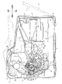
- FIG. 1 is a side sectional view showing a printer of an embodiment of an image forming apparatus of the present invention.
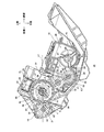
- FIG. 2 is a side cross-sectional view of the process cartridge shown in FIG. 1 (in a state where it is mounted on a main body casing).
- FIG. 3 is an enlarged view of a main part showing a contact portion between a transfer roller and a photosensitive drum shown in FIG. 2.
- Printer A printer 1 as an example of an image forming apparatus includes a substantially box-shaped main body casing 2 as shown in FIG.
- the printer 1 includes a sheet feeding unit 3 for feeding a sheet S as an example of a recording medium and an image forming unit 4 for forming an image on the fed sheet S in the main body casing 2. It has.
- the cartridge opening 5 is formed through the upper end of the main casing 2 in the vertical direction.
- the paper opening 6 is formed to penetrate in the front-rear direction at the lower end of the front end of the main casing 2.
- the top cover 7 is swingably (moved) between a closed position for closing the cartridge opening 5 and an open position for opening the cartridge opening 5 with the rear end as a fulcrum (shown in FIG. 1). (See the two-dot chain line).
- the paper stacking portion 9 is communicated with the outside of the main casing 2 through the paper opening 6.
- the sheet S is stacked on the upper surface of the sheet feed cover 8 while the sheet feed cover 8 is disposed at the second position, and the rear part is loaded on the sheet via the sheet opening 6. Stacked in the placement unit 9.
- the paper feeding unit 3 includes a pickup roller 11 disposed on the upper side of the rear end portion of the paper placing unit 9, a paper feeding roller 12 disposed on the rear side of the pickup roller 11, and a rear lower side of the paper feeding roller 12.
- the sheet feeding pad 13 is disposed opposite to the sheet feeding side, and the sheet feeding path 14 extends continuously upward from the rear end portion of the sheet feeding pad 13.
- (3) Image Forming Unit The image forming unit 4 includes a process cartridge 15, a scanner unit 16 as an example of an exposure device, and a fixing unit 17. (3-1) Process Cartridge
- the process cartridge 15 is configured to be detachable from the main casing 2 and is mounted on the main casing 2 above the rear portion of the paper feed unit 3.
- the process cartridge 15 includes a drum cartridge 18 configured to be detachable from the main body casing 2 and a developing cartridge 19 configured to be detachable from the drum cartridge 18.
- the drum cartridge 18 includes a drum frame 50 as shown in FIG.
- the drum frame 50 has a rear portion formed as a drum accommodating portion 51 and a front portion formed as a cartridge mounting portion 52.
- the drum accommodating part 51 is formed in the substantially box shape extended in the left-right direction and open
- the front-end part is divided as the drum opening 53 as an example of exposure opening part (refer FIG. 1). .
- the drum accommodating portion 51 accommodates a photosensitive drum 20, a transfer roller 21, and a scorotron charger 22 as an example of a charger.
- the photosensitive drum 20 includes a drum body 57 and a drum shaft 58.
- the drum shaft 58 is made of metal and has a substantially cylindrical shape extending in the left-right direction, and the length in the left-right direction is longer than the length in the left-right direction of the drum body 57.
- the drum shaft 58 is inserted into the drum main body 57 so as to be relatively rotatable so that the central axis thereof coincides with the central axis of the drum main body 57.
- the photosensitive drum 20 is configured to be rotatable about the center axis A1 (an example of the first axis) of the drum main body 57 by supporting the left and right ends of the drum shaft 58 with the drum housing 51. ing.
- the drum main body 57 receives a driving force from a driving source (not shown) such as a motor provided in the main body casing 2 during an image forming operation (described later), and rotates in the rotational direction X (left side view) indicated by an arrow. It is rotated clockwise.
- a driving source such as a motor provided in the main body casing 2 during an image forming operation (described later)
- X left side view
- the transfer roller 21 includes a metal transfer roller shaft 59 extending in the left-right direction and a roller body 60 that covers the transfer roller shaft 59 so that both left and right ends of the transfer roller shaft 59 are exposed.
- the roller body 60 is made of conductive rubber or conductive sponge.
- the transfer roller 21 is provided at the rear end portion of the drum accommodating portion 51 so that the roller main body 60 is pressed against the drum main body 57 from the rear side.
- the transfer roller 21 is disposed on the rear side of the photosensitive drum 20 so that the center axis A ⁇ b> 2 (described later) is slightly below the center axis A ⁇ b> 1 of the photosensitive drum 20. Has been placed.
- the lower end edge of the transfer roller 21 is disposed above the lower end edge of the photosensitive drum 20 as shown in FIG.
- the self-weight of the transfer roller 21 does not affect the pressure (transfer pressure) at which the transfer roller 21 is pressed against the photosensitive drum 20.
- FIG. 3 it passes through a virtual line segment L1 connecting a central axis A2 (described later) of the transfer roller 21 and a central axis A1 of the photosensitive drum 20, and a central axis A1 of the photosensitive drum 20.
- the acute angle ⁇ formed by the imaginary straight line L4 extending horizontally along the front-rear direction is, for example, 0 ° to 10 °, preferably about 3 °.
- paper S can be fed at the contact portion N (see FIG. 3) between the roller main body 60 of the transfer roller 21 and the drum main body 57 of the photosensitive drum 20, while passing through the contact portion N.
- the conveyed sheet S is conveyed slightly forward toward the fixing unit 17 (between a heating roller 38 (described later) and a pressure roller 39 (described later)).
- the contact portion N between the roller body 60 and the drum body 57 is entirely below the imaginary straight line L4, that is, below the center axis A1 of the photosensitive drum 20. positioned.
- the transfer roller 21 is supported by the drum housing portion 51 at the left and right ends of the transfer roller shaft 59, and the center axis A2 (an example of the third axis) is the center of rotation. It is configured to be rotatable.
- the transfer roller 21 rotates in the rotation direction Y (counterclockwise in the left side view) indicated by an arrow due to friction between the roller main body 60 and the drum main body 57.
- a transfer bias for example, ⁇ 2000 V
- a power source not shown
- the scorotron charger 22 includes a charging wire 23 (see FIG. 1) and a grid 24.
- the charging wire 23 is stretched so as to extend in the left-right direction, and is opposed to the front upper side of the photosensitive drum 20 with an interval.
- the grid 24 is formed in a substantially U shape in a side view opened toward the front upper side, and is provided so as to surround the charging wire 23 from the rear lower side.
- the scorotron charger 22 is disposed on the upper end portion of the drum housing portion 51 so that the lower end portion of the grid 24 is opposed to the peripheral surface of the drum main body 57 with an interval on the front upper side of the photosensitive drum 20. Is provided. That is, the scorotron charger 22 is disposed to face the photosensitive drum 20 with an interval above the central axis A1.
- the scorotron charger 22 is disposed with respect to the transfer roller 21 at a distance in the circumferential direction of the photosensitive drum 20 (drum body 57), and the center axis A ⁇ b> 1 of the photosensitive drum 20 and the transfer roller 21.
- the angle formed by the virtual line segment L1 connecting the central axis line A2 and the virtual line segment L2 connecting the central axis line A1 of the photosensitive drum 20 and the charging wire 23 is approximately 120 °. Yes.
- a paper feed opening 54 for feeding the paper S to the contact portion N between the roller main body 60 and the drum main body 57 and a paper S that has passed through the contact portion N are discharged.
- the paper discharge opening 55 is formed.
- the paper feed opening 54 is formed so as to penetrate in the vertical direction at a substantially central portion in the front-rear direction at the lower end portion of the drum accommodating portion 51 so as to be positioned in front of and below the contact portion N.
- the paper discharge opening 55 penetrates in the vertical direction in the rear portion of the upper end portion of the drum housing portion 51, specifically, on the rear side of the scorotron charger 22 so as to be positioned in front of and above the contact portion N. Is formed. That is, the paper discharge opening 55 is formed between the scorotron charger 22 and the transfer roller 21 in the circumferential direction of the drum body 57.
- the cartridge mounting portion 52 is formed in a substantially box shape whose upper and rear sides are opened so as to allow the mounting and dismounting of the developing cartridge 19, and communicates with the drum housing portion 51 via the drum opening 53.
- the cartridge mounting portion 52 is provided such that a rear end portion thereof is connected to a front end portion of the drum housing portion 51 and is inclined downward toward the front. (3-1-2) Developing Cartridge
- the developing cartridge 19 is detachably mounted on the cartridge mounting portion 52 of the drum cartridge 18 and is disposed on the front lower side of the photosensitive drum 20.
- the developing cartridge 19 includes a developing frame 25.
- the developing frame 25 is formed in a substantially box shape extending in the left-right direction, and a toner storage chamber 26 and a developing chamber 27 are formed side by side in the interior thereof.
- the toner storage chamber 26 and the developing chamber 27 are formed to have substantially the same volume, and communicate with each other through a communication port 28.
- the toner storage chamber 26 stores toner (an example of a developer), and an agitator 29 is provided at a substantially central portion in the front-rear and vertical directions. That is, the agitator 29 is disposed below the photosensitive drum 20.
- a supply roller groove 30, a developing roller facing surface 31, and a lower film attaching surface 32 are formed on the upper surface of the lower wall.
- the supply roller groove 30 has a substantially semicircular shape along the peripheral surface of a supply roller 33 (described later), and is formed so as to be recessed downward in the rearward direction.
- the developing roller facing surface 31 has a substantially arc shape along the peripheral surface of the developing roller 34 (described later), and is formed so as to extend continuously rearward from the rear end portion of the supply roller groove 30.
- the lower film attaching surface 32 is formed continuously from the rear end portion of the developing roller facing surface 31 so as to incline slightly upward toward the rear. That is, the lower film attaching surface 32 is disposed above the developing roller facing surface 31.
- the lower film attaching surface 32 is disposed to face the lower portion of the drum body 57 of the photosensitive drum 20 with an interval in the vertical direction, and the center of the photosensitive drum 20 is projected when projected in the vertical direction. It arrange
- the developing chamber 27 is provided with a supply roller 33, a developing roller 34, a layer thickness regulating blade 35, and a lower film 36 as an example of a film member.
- the supply roller 33 includes a metal supply roller shaft 63 that extends in the left-right direction, and a conductive sponge roller 64 that covers the supply roller shaft 63 so that both left and right ends of the supply roller shaft 63 are exposed.
- the supply roller 33 is disposed on the rear side of the toner storage chamber 26 so that the lower portion thereof is disposed in the supply roller groove 30, and is substantially the same height as the toner storage chamber 26 in the vertical direction. Is located.
- the supply roller 33 is configured to be rotatable around the central axis A3 at the front side portion of the developing chamber 27 by supporting the left and right ends of the supply roller shaft 63 on the developing frame 25.
- the driving force from a driving source (not shown) such as a motor provided in the main body casing 2 is transmitted to the supply roller 33 during image formation (described later). Then, the supply roller 33 rotates in the rotation direction indicated by the arrow in FIG. 2 (counterclockwise as viewed from the left side) so that the supply roller 33 rotates in a direction opposite to the development roller 34 at a portion facing the development roller 34 (described later). Driven.
- a supply bias (for example, +400 V) is applied to the supply roller shaft 63 of the supply roller 33 from a power source (not shown) provided in the main body casing 2 during image formation (described later).
- the developing roller 34 includes a metal developing roller shaft 65 extending in the left-right direction, and a conductive rubber roller 66 that covers the developing roller shaft 65 so that both left and right ends of the developing roller shaft 65 are exposed.
- the developing roller 34 is disposed such that the peripheral surface of the lower portion of the rubber roller 66 and the developing roller facing surface 31 are opposed to each other with a space therebetween.
- the developing roller 34 is provided so as to come into contact with the supply roller 33 from the upper rear side, and its upper and rear portions are exposed from the developing chamber 27. Is touching. That is, the developing roller 34 is disposed on the upper rear side of the supply roller 33 and on the lower front side of the photosensitive drum 20 so as to be sandwiched between the supply roller 33 and the photosensitive drum 20. In other words, the supply roller 33 is disposed on the opposite side of the photosensitive drum 20 with respect to the developing roller 34.
- the central axis A4 (described later) of the developing roller 34 is arranged to be positioned below the central axis A1 of the photosensitive drum 20.
- the central axis A1 of the photosensitive drum 20, the central axis A4 (described later) of the developing roller 34, and the central axis A3 of the supply roller 33 are located on substantially the same virtual straight line L3 along the radial direction of the drum body 57. .
- the developing roller 34 is disposed at a distance from the scorotron charger 22 in the circumferential direction of the drum body 57.
- the developing roller 34 is a virtual line L2 that connects the central axis A1 of the photosensitive drum 20 and the charging wire 23 and a virtual line that passes through the central axis A1 of the photosensitive drum 20 and the central axis A4 of the developing roller 34.
- the angle formed by the line segment L3 is about 120 °. That is, the developing roller 34, the scorotron charger 22, and the transfer roller 21 are arranged at substantially equal intervals in the circumferential direction of the drum body 57. Note that only the rubber roller 66 of the developing roller 34 and the roller body 60 of the transfer roller 21 are in contact with the drum body 57.
- the developing roller 34 is supported by the developing frame 25 at both left and right ends of the developing roller shaft 65, so that the center axis A4 (an example of the second axis) is the center of rotation in the rear portion of the developing chamber 27. Is configured to be rotatable.
- a driving force from a driving source such as a motor provided in the main body casing 2 is transmitted to the developing roller 34 during an image forming operation (described later).
- a driving force from a driving source such as a motor provided in the main body casing 2 is transmitted to the developing roller 34 during an image forming operation (described later).
- the developing roller 34 is rotationally driven in a rotation direction Z (counterclockwise as viewed from the left side) indicated by an arrow shown in FIG.
- the peripheral speed of the developing roller 34 is, for example, 1.35 to 1.65 times, preferably 1.5 times the peripheral speed of the photosensitive drum 20 (drum body 57).
- a developing bias (for example, +300 V) is applied to the developing roller shaft 65 of the developing roller 34 from a power source (not shown) provided in the main body casing 2 during image formation (described later).
- the upper end portion of the layer thickness regulating blade 35 is fixed to the rear end portion of the upper wall of the developing chamber 27, and the lower end portion thereof is in contact with the peripheral surface of the rubber roller 66 from the front side.
- the lower portion of the lower film 36 is fixed to the lower film attaching surface 32, and the front end thereof is in contact with the peripheral surface of the rubber roller 66 above the developing roller facing surface 31. Thereby, as for the lower film 36, the rear-end part is located above the front-end part.
- the lower film 36 is disposed on the lower side with respect to the photosensitive drum 20 so that the rear side portion thereof overlaps the central axis A1 of the photosensitive drum 20 when projected in the vertical direction.
- the scanner unit 16 is disposed on the front side of the process cartridge 15 so as to face the photosensitive drum 20 with a space in the front-rear direction.
- the scanner unit 16 emits a laser beam L (an example of a laser beam) toward the photosensitive drum 20 based on the image data to expose the peripheral surface of the photosensitive drum 20.
- a laser beam L an example of a laser beam
- the laser beam L is emitted backward from the scanner unit 16 to expose the peripheral surface at the front end portion of the photosensitive drum 20. That is, the exposure point at which the photosensitive drum 20 is exposed (the peripheral surface at the front end of the photosensitive drum 20) is the contact portion N where the photosensitive drum 20 and the transfer roller 21 are in contact with the central axis A1 of the photosensitive drum 20. It is set on the opposite side.
- the developing cartridge 19 is arranged below the emission locus of the laser beam L, and the scorotron charger 22 is arranged above the emission locus of the laser beam L.
- a guide portion 37 for guiding the attachment / detachment of the process cartridge 15 is provided on the inner side surface of the main body casing 2 between the scanner unit 16 and the photosensitive drum 20.
- the process cartridge 15 is guided by the guide portion 37, so that the developing cartridge 19 attached to the drum cartridge 18 has a lower emission locus of the laser beam L. Pass from the top to the top.
- the fixing unit 17 is disposed above the rear portion of the drum cartridge 18. Specifically, the fixing unit 17 includes a heating roller 38 disposed above the scorotron charger 22 and a pressure roller 39 pressed against the heating roller 38 from the rear upper side.
- the heating roller 38 is disposed in the vicinity of the upper end portion (open end portion) of the grid 24 of the scorotron charger 22.
- Image Forming Operation (1) Developing Operation As shown in FIG. 2, the toner in the toner storage chamber 26 of the developing cartridge 19 is supplied to the sponge roller 64 of the supply roller 33 through the communication port 28 by the rotation of the agitator 29. Further, it is supplied to the rubber roller 66 of the developing roller 34 and is frictionally charged to a positive polarity between the sponge roller 64 and the rubber roller 66.
- the toner charged to the positive polarity is regulated by the layer thickness regulating blade 35 as the developing roller 34 rotates, and is carried on the peripheral surface of the rubber roller 66 as a thin layer having a constant thickness.
- the peripheral surface of the drum body 57 of the photosensitive drum 20 is uniformly charged by, for example, +630 V by the scorotron charger 22, and then exposed by the laser beam L of the scanner unit 16.
- the laser beam L emitted from the scanner unit 16 passes above the developing cartridge 19, then passes through the drum opening 53, and further in the circumferential direction of the drum body 57. It passes between the charger 22 and the developing roller 34 and reaches the peripheral surface of the drum body 57.
- an electrostatic latent image based on the image data is formed on the peripheral surface of the drum body 57.
- the potential of the portion where the electrostatic latent image is formed on the peripheral surface of the drum body 57 (that is, the exposed portion) is, for example, + 100V.
- the electrostatic latent image on the peripheral surface of the drum body 57 and the rubber roller 66 are opposed to each other by rotating the developing roller 34 and the photosensitive drum 20.
- a predetermined amount of toner is supplied to the electrostatic latent image on the peripheral surface of the drum main body 57 by the developing bias with the toner carried on the rubber roller 66. That is, the amount of toner supplied to the electrostatic latent image is controlled by the developing bias applied to the developing roller 34.
- the sheet S passes through the contact portion N (between the drum body 57 and the roller body 60) from the lower side toward the upper side by the rotation of the drum body 57.
- the toner image (visible image) carried on the peripheral surface of the drum body 57 is transferred to the paper S by the transfer bias applied to the transfer roller 21 (transfer operation).
- the sheet S on which the toner image is transferred passes through the discharging opening 55 and is conveyed between the heating roller 38 and the pressure roller 39.
- the paper S is conveyed toward the paper discharge roller 40 and is discharged onto the paper discharge tray 41 of the main casing 2 by the paper discharge roller 40 (paper discharge operation).
- the sheet S is fed from the sheet placing portion 9 and passes between the photosensitive drum 20 and the transfer roller 21 (contact portion N), and then between the heating roller 38 and the pressure roller 39. After passing, the paper is transported through a substantially C-shaped transport path in side view so as to be discharged onto the paper discharge tray 41. 3. Removal / collection operation (cleaning operation) of deposits adhering to the photosensitive drum In the image forming operation of the printer 1, deposits may adhere to the peripheral surface of the drum body 57 of the photosensitive drum 20.
- deposits include toner remaining on the peripheral surface of the drum body 57 after the transfer operation (hereinafter referred to as “transfer residual toner”), and the sheet S passes through the contact portion N in the transfer operation.
- transfer residual toner toner remaining on the peripheral surface of the drum body 57 after the transfer operation
- foreign matter such as paper dust attached to the peripheral surface of the drum main body 57 is included.
- such deposits are removed and collected by the developing roller 34 during the image forming operation. That is, the developing roller 34 removes and collects deposits on the peripheral surface of the drum body 57 while supplying toner to the electrostatic latent image on the peripheral surface of the drum body 57 during the image forming operation.
- the transfer residual toner is uniformly charged to the positive polarity by facing the scorotron charger 22 as the photosensitive drum 20 rotates. At this time, the untransferred toner has substantially the same potential as the peripheral surface of the drum body 57 of the photosensitive drum 20.
- the transfer residual toner charged to substantially the same potential as the peripheral surface of the drum body 57 moves from the photosensitive drum 20 to the developing roller 34 due to a potential difference with the developing roller 34 when facing the rubber roller 66, and the rubber roller 66 is electrostatically held on the peripheral surface of 66.
- the developing roller 34 electrically supplies a predetermined amount of toner to the electrostatic latent image on the peripheral surface of the drum body 57 as described above.
- the untransferred toner held on the peripheral surface of the rubber roller 66 is moved and stored (collected) in the developing frame 25 as the developing roller 34 rotates, or the peripheral surface of the drum main body 57 again. To the electrostatic latent image.
- the adhering matter is a foreign matter such as paper dust
- the foreign matter such as paper dust tends to be negatively charged relative to the transfer residual toner, and even if it is opposed to the scorotron charger 22, the positive electrode Is not electrically charged.
- the foreign matter held on the peripheral surface of the rubber roller 66 is moved into the developing frame 25 as the developing roller 34 rotates, and is dropped by gravity, for example, and collected (stored) in the developing frame 25.
- the central axis A4 of the developing roller 34 is arranged so as to be located lower (vertically in the vertical direction) than the central axis A1 of the photosensitive drum 20.
- the adhering matter for example, transfer residual toner or foreign matter such as paper dust
- adhering to the peripheral surface of the drum body 57 of the photosensitive drum 20 is reliably collected by the rubber roller 66 of the developing roller 34 using gravity. Is done.
- the cleaner-less method can be adopted, but it is possible to reliably suppress the deposits from remaining on the peripheral surface of the drum main body 57, and to suppress the occurrence of image formation defects resulting therefrom.
- the peripheral surface of the drum main body 57 can be prevented from being damaged, and deposits adhering to the peripheral surface of the drum main body 57 can be reliably collected, and the printer 1 can be simplified, downsized, and reduced in cost. be able to.
- the transfer roller 21 is arranged such that the central axis A ⁇ b> 2 is located below (vertically in the vertical direction) the central axis A ⁇ b> 1 of the photosensitive drum 20. ing.
- the transfer roller 21 is disposed so that all of the contact portions N are located below the center axis A ⁇ b> 1 (downward in the vertical direction). In other words, each of the rotation direction X upstream end and the rotation direction X downstream end of the contact portion N is positioned below the central axis A1.
- the printer 1 includes a scorotron charger 22 configured to charge the peripheral surface of the drum body 57 of the photosensitive drum 20. Above the axis A ⁇ b> 1 (upward in the vertical direction), the drum body 57 is disposed to face the drum body 57 with an interval.
- Each of the developing roller 34 and the transfer roller 21 is such that the center axis A4 and the center axis A2 are located below the center axis A1, and the rubber roller 66 and the roller body 60 are drums of the photosensitive drum 20, respectively. It arrange
- the photosensitive drum 20 is supported on the developing roller 34 and the transfer roller 21 from below.
- the relative positional relationship between the scorotron charger 22 disposed above the central axis A1 in the vertical direction and the drum body 57 can be kept constant, and the peripheral surface of the drum body 57 can be charged reliably. Can be made.
- toner transfer residual toner
- toner transfer residual toner
- the untransferred toner is charged to substantially the same potential as the peripheral surface of the drum main body 57 by facing the scorotron charger 22, and when the toner remains in contact with the rubber roller 66, the toner remaining on the transfer roller is caused by the potential difference with the developing roller 34. Recovered reliably.
- the drum accommodating portion 51 has a paper discharge opening 55 between the scorotron charger 22 and the transfer roller 21 in the circumferential direction of the drum body 57 of the photosensitive drum 20. And a drum opening 53 is defined at the front end of the drum housing 51.
- the laser beam L from the scanner unit 16 passes through the drum opening 53 and the scorotron charger 22 and the developing roller 34 in the circumferential direction of the drum main body 57 during the image forming operation. And the peripheral surface of the drum body 57 is exposed.
- the scorotron charger 22, the transfer roller 21, and the developing roller 34 are each efficiently arranged, and the optimum arrangement in the cleanerless system is ensured.
- the supply roller 33 is disposed on the opposite side of the photosensitive drum 20 with respect to the developing roller 34, and the sponge roller 64 of the supply roller 33 is replaced with the rubber roller 66 of the developing roller 34. Since they face each other, the developing roller 34 is supported by the supply roller 33 from the opposite side of the photosensitive drum 20.
- the developing roller 34 can be prevented from being bent, the relative positional relationship between the developing roller 34 and the photosensitive drum 20 can be kept constant, and stable contact between the rubber roller 66 and the drum body 57 can be ensured. Can do.
- the developing roller 34 can stably supply the toner to the electrostatic latent image and can more reliably collect the deposits attached to the peripheral surface of the drum body 57.
- the printer 1 has a lower film 36 disposed below the drum body 57 of the photosensitive drum 20 so as to overlap the central axis A1 when projected in the vertical direction. It has.
- the rear end of the lower film 36 is disposed above the front end that contacts the peripheral surface of the rubber roller 66, the deposits deposited on the upper surface of the lower film 36 are removed from the upper surface of the lower film 36. And move toward the front, and reach the peripheral surface of the rubber roller 66.
- the adhered matter that has reached the peripheral surface of the rubber roller 66 is held on the peripheral surface of the rubber roller 66 and is reliably collected in the developing frame 25 as the developing roller 34 is driven to rotate.
- the printer 1 described above is an embodiment of the image forming apparatus of the present invention, and the present invention is not limited to the above-described embodiment.
- the cleaning operation is performed during the image forming operation.
- the transfer residual toner adhering to the peripheral surface of the drum body 57 is more reliably held on the peripheral surface of the rubber roller 66. Therefore, the transfer residual toner can be collected or reused more reliably.
- the image forming apparatus of the present invention can be configured as a color printer in addition to the above-described monochrome printer.
- the image forming apparatus When the image forming apparatus is configured as a color printer, the image forming apparatus includes a direct tandem type color printer including a plurality of photosensitive members and a recording medium conveying member, a plurality of photosensitive members, an intermediate transfer member, and a transfer member. It can be configured as an intermediate transfer type tandem color printer.
- process cartridge 15 may be configured as an integral type integrally including the drum cartridge 18 and the developing cartridge 19 in addition to the separation type in which the drum cartridge 18 and the developing cartridge 19 are separated as described above.
- the photosensitive drum 20 can be provided in the main casing 2 and only the developing cartridge 19 can be attached to and detached from the main casing 2.
- the developing cartridge 19 can be configured such that a toner cartridge that contains toner is detachably attached to a frame having the developing roller 34.
- a conveying member such as an auger screw or a conveying belt can be applied.
- a non-contact charger such as a corotron charger, a sawtooth discharge member, or a contact charger such as a charging roller may be applied. it can.
- the image forming apparatus of the present invention can also be configured as a multi-function machine equipped with an image reading unit and the like.
Landscapes
- Physics & Mathematics (AREA)
- General Physics & Mathematics (AREA)
- Engineering & Computer Science (AREA)
- Computer Vision & Pattern Recognition (AREA)
- Electrophotography Configuration And Component (AREA)
- Cleaning In Electrography (AREA)
- Electrostatic Charge, Transfer And Separation In Electrography (AREA)
- Dry Development In Electrophotography (AREA)
Abstract
Provided is an image formation device capable of suppressing damage to the peripheral surface of a photosensitive drum, and definitively removing and collecting an adhering substance which adheres to the peripheral surface of the photosensitive drum. A printer (1) equipped with a photosensitive drum (20) for rotating around a center-axis line (A1), and a developing roller (34) for rotating around a center-axis line (A4), wherein the developing roller (34) is positioned in a manner such that the center-axis line (A4) is below (bottom-side in vertical direction) the center-axis line (A1). Consequently, the printer (1) is configured in a manner such that it is possible to supply toner to the photosensitive drum (20), and recover the adhering substance which adheres to the peripheral surface of the photosensitive drum (20).
Description
本発明は、電子写真方式が採用される画像形成装置に関する。
The present invention relates to an image forming apparatus employing an electrophotographic system.
電子写真方式の画像形成装置として、特許文献1に記載されているように、静電潜像が形成される感光体ドラムと、感光体ドラムに対向接触され、静電潜像にトナーを供給する現像ローラと、画像形成の過程において感光体ドラムの周面に付着する付着物(例えば、トナー)を、感光体ドラムの周面から掻き落とすためのクリーニングブレードとを備えるプリンタが知られている。
As an electrophotographic image forming apparatus, as described in Patent Document 1, a photosensitive drum on which an electrostatic latent image is formed and a photosensitive drum are opposed to and supplied with toner. 2. Description of the Related Art A printer is known that includes a developing roller and a cleaning blade for scraping off deposits (for example, toner) adhering to the circumferential surface of the photosensitive drum during image formation from the circumferential surface of the photosensitive drum.
そして、このようなプリンタでは、クリーニングブレードの先端部が感光体ドラムの周面に当接することにより、感光体ドラムの周面に付着する付着物が掻き落とされている。
In such a printer, the tip of the cleaning blade comes into contact with the peripheral surface of the photoconductive drum, and the adhering matter adhering to the peripheral surface of the photoconductive drum is scraped off.
しかし、特許文献1に記載のプリンタでは、クリーニングブレードの先端部が、常に、感光体ドラムの周面に当接しているので、画像形成動作が繰り返されることにより、感光体ドラムの周面が傷つく場合がある。
However, in the printer described in Patent Document 1, since the tip of the cleaning blade is always in contact with the peripheral surface of the photosensitive drum, the peripheral surface of the photosensitive drum is damaged by repeating the image forming operation. There is a case.
そこで、本発明の目的は、感光ドラムの周面が傷つくことを抑制でき、かつ、感光ドラムの周面に付着する付着物を良好に除去・回収できる画像形成装置を提供することにある。
Therefore, an object of the present invention is to provide an image forming apparatus that can suppress damage to the peripheral surface of the photosensitive drum and that can satisfactorily remove and collect deposits adhering to the peripheral surface of the photosensitive drum.
(1)上記した目的を達成するために、本発明の画像形成装置は、第1の軸線について回転するように構成される感光ドラムと、感光ドラムに接触し、第2の軸線について回転することで感光ドラムに現像剤を供給して感光ドラムの周面に可視像を形成するように構成される現像ローラとを備えている。
(1) In order to achieve the above-described object, an image forming apparatus of the present invention is configured to rotate about a first axis, a photosensitive drum configured to rotate about the first axis, and contact with the photosensitive drum and rotate about the second axis. And a developing roller configured to supply a developer to the photosensitive drum to form a visible image on the peripheral surface of the photosensitive drum.
感光ドラムの周面に付着する付着物は、現像ローラのみによって回収される。
Deposits adhering to the peripheral surface of the photosensitive drum are collected only by the developing roller.
第2の軸線は、第1の軸線よりも鉛直方向下側に位置するように配置されている。
The second axis is arranged so as to be located on the lower side in the vertical direction than the first axis.
しかるに、現像ローラが、静電潜像に現像剤を供給しつつ、感光ドラムの周面に付着する付着物を回収する、いわゆるクリーナレス方式では、感光ドラムの周面に付着する付着物(例えば、現像剤や、紙粉などの異物)を除去するためのクリーナ装置(例えば、クリーニングブレードなど)が不要である。
However, in the so-called cleanerless system in which the developing roller collects the deposits attached to the peripheral surface of the photosensitive drum while supplying the developer to the electrostatic latent image, the deposits attached to the peripheral surface of the photosensitive drum (for example, In addition, there is no need for a cleaner device (for example, a cleaning blade or the like) for removing a developer or foreign matter such as paper dust.
そのため、感光ドラムの周面が傷つくことを抑制でき、かつ、感光ドラムの周面に付着する付着物を除去・回収できながら、画像形成装置の簡略化、小型化およびコストの低減化を図ることができる。
Therefore, the image forming apparatus can be simplified, downsized, and cost can be reduced while the peripheral surface of the photosensitive drum can be prevented from being damaged and the deposits attached to the peripheral surface of the photosensitive drum can be removed and collected. Can do.
しかし、このようなクリーナレス方式では、感光ドラムの周面に付着する付着物を十分に回収できない場合がある。そうすると、感光ドラムの周面に付着物が残存し、それに起因する画像形成不良が生じる場合がある。
However, with such a cleaner-less method, there are cases where the deposits adhering to the peripheral surface of the photosensitive drum cannot be sufficiently recovered. As a result, deposits may remain on the peripheral surface of the photosensitive drum, resulting in image formation defects.
一方、上記の構成によれば、現像ローラが、第2の軸線が感光ドラムの第1の軸線よりも鉛直方向下側に位置するように配置されているので、感光ドラムの周面に付着する付着物が、重力により、現像ローラに確実に回収される。
On the other hand, according to the configuration described above, the developing roller is disposed so that the second axis is positioned below the first axis of the photosensitive drum in the vertical direction, and therefore adheres to the circumferential surface of the photosensitive drum. Deposits are reliably collected on the developing roller by gravity.
そのため、クリーナレス方式を採用することができながら、感光ドラムの周面に付着物が残存することを確実に抑制でき、それに起因する画像形成不良の発生を抑制できる。
For this reason, it is possible to reliably suppress the deposits remaining on the peripheral surface of the photosensitive drum while adopting the cleaner-less method, and it is possible to suppress the occurrence of defective image formation due to it.
従って、感光ドラムの周面が傷つくことを抑制でき、かつ、感光ドラムの周面に付着する付着物を良好に回収できながら、画像形成装置の簡略化、小型化およびコストの低減化を図ることができる。
(2)また、画像形成装置は、感光ドラムに接触し、第3の軸線について回転するように構成される転写ローラであって、可視像を感光ドラムの周面から記録媒体に転写するように構成される転写ローラをさらに備えていてもよい。この場合、転写ローラは、第3の軸線が第1の軸線よりも鉛直方向下側に位置するように配置されている。 Accordingly, the image forming apparatus can be simplified, downsized, and cost can be reduced while the peripheral surface of the photosensitive drum can be prevented from being damaged and the deposits attached to the peripheral surface of the photosensitive drum can be recovered well. Can do.
(2) The image forming apparatus is a transfer roller configured to contact the photosensitive drum and rotate about the third axis so as to transfer the visible image from the peripheral surface of the photosensitive drum to the recording medium. A transfer roller configured as described above may be further provided. In this case, the transfer roller is disposed such that the third axis is positioned below the first axis in the vertical direction.
また、感光ドラムには、現像ローラおよび転写ローラのみが接触されていてもよい。
Further, only the developing roller and the transfer roller may be in contact with the photosensitive drum.
しかるに、記録媒体には、通常、異物(例えば、紙粉)が付着しており、可視像が記録媒体に転写されるときに、その異物が感光ドラムの周面に付着する場合がある。
However, foreign matter (for example, paper dust) is usually attached to the recording medium, and when the visible image is transferred to the recording medium, the foreign matter may adhere to the peripheral surface of the photosensitive drum.
この点、上記の構成によれば、転写ローラが、第3の軸線が第1の軸線よりも鉛直方向下側に位置するように配置されているので、記録媒体が感光ドラムと転写ローラとの接触部分を通過するときに、記録媒体における感光ドラム側の面に付着する異物には、記録媒体に向かうように重力が作用する。
In this regard, according to the above-described configuration, the transfer roller is disposed such that the third axis is positioned below the first axis in the vertical direction, so that the recording medium is formed between the photosensitive drum and the transfer roller. Gravity acts on the foreign matter adhering to the surface of the recording medium on the photosensitive drum side when passing through the contact portion so as to face the recording medium.
そのため、異物が、記録媒体から感光ドラムの周面に移動することが抑制される。
Therefore, it is possible to prevent foreign matter from moving from the recording medium to the peripheral surface of the photosensitive drum.
その結果、感光ドラムの周面に記録媒体からの異物が付着することを抑制でき、感光ドラムの周面に付着する付着物の低減を図ることができる。
(3)また、感光ドラムは、記録媒体を転写ローラとの接触部分を通過させるように、回転可能に構成されていてもよい。 As a result, it is possible to suppress foreign matter from the recording medium from adhering to the peripheral surface of the photosensitive drum, and it is possible to reduce the amount of deposits attached to the peripheral surface of the photosensitive drum.
(3) The photosensitive drum may be configured to be rotatable so that the recording medium passes through a contact portion with the transfer roller.
また、転写ローラは、感光ドラムとの接触部分における感光ドラムの回転方向上流側端部が第1の軸線よりも鉛直方向下側に位置するように配置されていてもよい。
In addition, the transfer roller may be arranged such that the upstream end portion in the rotation direction of the photosensitive drum at the contact portion with the photosensitive drum is positioned below the first axis in the vertical direction.
このような構成によれば、転写ローラと感光ドラムとの接触部分における回転方向上流側端部が、第1の軸線よりも鉛直方向下側に位置するので、重力によって、感光ドラムの周面に記録媒体からの異物が付着することを確実に抑制できる。
(4)また、転写ローラは、接触部分のすべてが第1の軸線よりも鉛直方向下側に位置するように配置されていてもよい。 According to such a configuration, the upstream end portion in the rotational direction at the contact portion between the transfer roller and the photosensitive drum is positioned below the first axis in the vertical direction. It is possible to reliably suppress the adhesion of foreign matter from the recording medium.
(4) Further, the transfer roller may be arranged so that all of the contact portions are positioned below the first axis in the vertical direction.
このような構成によれば、接触部分のすべてが第1の軸線よりも鉛直方向下側に位置するので、重力によって、感光ドラムの周面に記録媒体からの異物が付着することをより一層確実に抑制できる。
(5)また、画像形成装置は、感光ドラムの周面を帯電させるように構成される帯電器をさらに備えていてもよい。 According to such a configuration, since all of the contact portions are positioned vertically below the first axis, it is further ensured that foreign matter from the recording medium adheres to the peripheral surface of the photosensitive drum due to gravity. Can be suppressed.
(5) The image forming apparatus may further include a charger configured to charge the peripheral surface of the photosensitive drum.
この場合、帯電器は、第1の軸線よりも鉛直方向上側において、感光ドラムに対して間隔を隔てて対向配置されている。
In this case, the charger is disposed to be opposed to the photosensitive drum at an interval above the first axis in the vertical direction.
このような構成によれば、現像ローラおよび転写ローラのそれぞれは、第2の軸線および第3の軸線のそれぞれが第1の軸線よりも鉛直方向下側に位置し、かつ、感光ドラムに接触するように配置されている。
According to such a configuration, each of the developing roller and the transfer roller is such that each of the second axis and the third axis is positioned below the first axis in the vertical direction and contacts the photosensitive drum. Are arranged as follows.
そのため、感光ドラムは、現像ローラおよび転写ローラのそれぞれに鉛直方向下側から支持されている。
Therefore, the photosensitive drum is supported by the developing roller and the transfer roller from the lower side in the vertical direction.
その結果、第1の軸線よりも鉛直方向上側に配置される帯電器と、感光ドラムとの相対的な位置関係を一定に保つことができ、感光ドラムの周面を確実に帯電させることができる。従って、感光ドラムの周面を確実に帯電させることができる。
(6)また、画像形成装置は、感光ドラムの周面に静電潜像が形成されるように、感光ドラムに向けてレーザ光を出射可能に構成される露光装置をさらに備えていてもよい。 As a result, the relative positional relationship between the charging device arranged vertically above the first axis and the photosensitive drum can be kept constant, and the peripheral surface of the photosensitive drum can be reliably charged. . Therefore, the peripheral surface of the photosensitive drum can be reliably charged.
(6) The image forming apparatus may further include an exposure device configured to emit laser light toward the photosensitive drum so that an electrostatic latent image is formed on the peripheral surface of the photosensitive drum. .
また、感光ドラムの周方向における帯電器と転写ローラとの間から、感光ドラムと転写ローラとの接触部分を通過した記録媒体が排紙されてもよい。
Further, the recording medium that has passed through the contact portion between the photosensitive drum and the transfer roller may be discharged from between the charger and the transfer roller in the circumferential direction of the photosensitive drum.
また、感光ドラムの周方向における帯電器と現像ローラとの間を、レーザ光が通過してもよい。
Further, the laser beam may pass between the charger and the developing roller in the circumferential direction of the photosensitive drum.
このような構成によれば、感光ドラムの周方向において、帯電器と転写ローラとの間に排紙開口部が区画され、帯電器と現像ローラとの間に露光開口部が区画されている。
According to such a configuration, in the circumferential direction of the photosensitive drum, the paper discharge opening is defined between the charger and the transfer roller, and the exposure opening is defined between the charger and the developing roller.
つまり、感光ドラムの周方向において、帯電器、転写ローラおよび現像ローラのそれぞれが効率的に配置されており、クリーナレス方式における最適配置が確保されている。
That is, in the circumferential direction of the photosensitive drum, each of the charger, the transfer roller, and the developing roller is efficiently arranged, and the optimum arrangement in the cleanerless system is ensured.
そのため、感光ドラムの周面が傷つくこと抑制でき、かつ、感光ドラムの周面に付着する付着物を確実に回収できながら、画像形成装置の小型化を図ることができる。
(7)また、画像形成装置は、現像ローラに対向接触し、現像ローラに現像剤を供給するように構成される供給ローラをさらに備えていてもよい。 Therefore, the image forming apparatus can be downsized while the peripheral surface of the photosensitive drum can be prevented from being damaged, and the deposits attached to the peripheral surface of the photosensitive drum can be reliably collected.
(7) The image forming apparatus may further include a supply roller configured to face the developing roller and to supply the developer to the developing roller.
この場合、供給ローラは、現像ローラに対して感光ドラムの反対側に配置されている。
In this case, the supply roller is disposed on the opposite side of the photosensitive drum with respect to the developing roller.
このような構成によれば、供給ローラが、現像ローラに対して感光ドラムの反対側に配置され、かつ、現像ローラに対向接触しているので、現像ローラは、感光ドラムの反対側から供給ローラに支えられている。
According to such a configuration, since the supply roller is disposed on the opposite side of the photosensitive drum with respect to the developing roller and is opposed to the developing roller, the developing roller is supplied from the opposite side of the photosensitive drum. Supported by
そのため、現像ローラが撓むことを抑制でき、現像ローラと感光ドラムとの相対的な位置関係を一定に保つことができる。とりわけ、現像ローラと感光ドラムとが接触している場合には、安定した接触を確保することができる。
Therefore, the developing roller can be prevented from being bent, and the relative positional relationship between the developing roller and the photosensitive drum can be kept constant. In particular, when the developing roller and the photosensitive drum are in contact with each other, stable contact can be ensured.
その結果、現像ローラは、静電潜像に現像剤を安定して供給できるとともに、感光ドラムの周面に付着する付着物をより一層確実に回収できる。
(8)また、画像形成装置は、鉛直方向に投影したときに第1の軸線と重なるように、感光ドラムに対して鉛直方向下側に配置されるフィルム部材をさらに備えていてもよい。 As a result, the developing roller can stably supply the developer to the electrostatic latent image and can more reliably collect the deposits attached to the peripheral surface of the photosensitive drum.
(8) The image forming apparatus may further include a film member disposed on the lower side in the vertical direction with respect to the photosensitive drum so as to overlap the first axis when projected in the vertical direction.
この場合、フィルム部材は、その一部が、現像ローラの周面に接触されている。
In this case, a part of the film member is in contact with the peripheral surface of the developing roller.
このような構成によれば、感光ドラムの周面から重力により付着物が落下すると、フィルム部材上に堆積する。
According to such a configuration, when the deposit falls due to gravity from the peripheral surface of the photosensitive drum, it deposits on the film member.
そして、フィルム部材の少なくとも一部が、現像ローラの周面に接触されているので、堆積された付着物は、現像ローラの周面に回収される。
And, since at least a part of the film member is in contact with the peripheral surface of the developing roller, the deposited deposits are collected on the peripheral surface of the developing roller.
そのため、感光ドラムの周面から重力により付着物が落下しても、フィルム部材および現像ローラにより、感光ドラムの周辺が付着物により汚染されることが抑制できる。
Therefore, even if the deposit falls due to gravity from the peripheral surface of the photosensitive drum, the periphery of the photosensitive drum can be prevented from being contaminated by the deposit by the film member and the developing roller.
本発明によれば、感光ドラムの周面が傷つくこと抑制でき、かつ、感光ドラムの周面に付着する付着物を良好に回収できる。
According to the present invention, the peripheral surface of the photosensitive drum can be prevented from being damaged, and the deposits attached to the peripheral surface of the photosensitive drum can be recovered well.
1.プリンタ
画像形成装置の一例としてのプリンタ1は、図1に示すように、略ボックス形状の本体ケーシング2を備えている。 1.Printer A printer 1 as an example of an image forming apparatus includes a substantially box-shaped main body casing 2 as shown in FIG.
画像形成装置の一例としてのプリンタ1は、図1に示すように、略ボックス形状の本体ケーシング2を備えている。 1.
また、プリンタ1は、本体ケーシング2内において、記録媒体の一例としての用紙Sを給紙するための給紙部3と、給紙された用紙Sに画像を形成するための画像形成部4とを備えている。
In addition, the printer 1 includes a sheet feeding unit 3 for feeding a sheet S as an example of a recording medium and an image forming unit 4 for forming an image on the fed sheet S in the main body casing 2. It has.
なお、以下の説明において、方向について言及する場合には、プリンタ1を水平に載置した状態を基準として、図1における紙面右側を前側とし、図1における紙面左側を後側とする。また、プリンタ1を前側から見たときを左右の基準とし、図1の紙面手前側が左側であり、紙面奥側が右側である。
In the following description, when referring to the direction, the right side of the paper surface in FIG. 1 is the front side and the left side of the paper surface in FIG. 1 is the rear side, based on the state where the printer 1 is placed horizontally. Further, when the printer 1 is viewed from the front side, the left and right sides of FIG. 1 are the left side, and the back side of the page is the right side.
すなわち、前後方向および左右方向のそれぞれが水平方向であり、上下方向が鉛直方向である。
(1)本体ケーシング
本体ケーシング2には、プロセスカートリッジ15(後述)を着脱するためのカートリッジ開口部5と、用紙Sを導入するための用紙開口部6とが形成されている。 That is, the front-rear direction and the left-right direction are horizontal directions, and the up-down direction is a vertical direction.
(1) Main Body Casing Themain body casing 2 is formed with a cartridge opening 5 for attaching / detaching a process cartridge 15 (described later) and a paper opening 6 for introducing the paper S.
(1)本体ケーシング
本体ケーシング2には、プロセスカートリッジ15(後述)を着脱するためのカートリッジ開口部5と、用紙Sを導入するための用紙開口部6とが形成されている。 That is, the front-rear direction and the left-right direction are horizontal directions, and the up-down direction is a vertical direction.
(1) Main Body Casing The
カートリッジ開口部5は、本体ケーシング2の上端部において、上下方向に貫通形成されている。
The cartridge opening 5 is formed through the upper end of the main casing 2 in the vertical direction.
用紙開口部6は、本体ケーシング2の前端部における下端部において、前後方向に貫通形成されている。
The paper opening 6 is formed to penetrate in the front-rear direction at the lower end of the front end of the main casing 2.
また、本体ケーシング2には、その上端部に、トップカバー7が設けられ、その前端部に、給紙カバー8が設けられている。トップカバー7には、用紙Sが排紙される排紙トレイ41が設けられている。
Further, the main body casing 2 is provided with a top cover 7 at its upper end and a paper feed cover 8 at its front end. The top cover 7 is provided with a paper discharge tray 41 from which the paper S is discharged.
トップカバー7は、その後端部を支点として、カートリッジ開口部5を閉鎖する閉鎖位置と、カートリッジ開口部5を開放する開放位置とに揺動(移動)可能に設けられている(図1に示す二点鎖線参照)。
The top cover 7 is swingably (moved) between a closed position for closing the cartridge opening 5 and an open position for opening the cartridge opening 5 with the rear end as a fulcrum (shown in FIG. 1). (See the two-dot chain line).
給紙カバー8は、その下端部を支点として、用紙開口部6を閉鎖する第1位置と、用紙開口部6を開放する第2位置とに揺動(移動)可能に設けられている(図1に示す二点鎖線参照)。
(2)給紙部
給紙部3は、本体ケーシング2の底部に設けられる用紙載置部9を備えている。 Thepaper feed cover 8 is provided so as to be swingable (movable) between a first position where the paper opening 6 is closed and a second position where the paper opening 6 is opened with the lower end portion as a fulcrum (see FIG. 1).
(2) Paper Feed Unit Thepaper feed unit 3 includes a paper placement unit 9 provided at the bottom of the main casing 2.
(2)給紙部
給紙部3は、本体ケーシング2の底部に設けられる用紙載置部9を備えている。 The
(2) Paper Feed Unit The
用紙載置部9は、用紙開口部6を介して、本体ケーシング2の外部と連通されている。
The paper stacking portion 9 is communicated with the outside of the main casing 2 through the paper opening 6.
そして、用紙Sは、給紙カバー8が第2位置に配置された状態において、その前側部分が給紙カバー8の上面にスタックされるとともに、その後側部分が用紙開口部6を介して用紙載置部9内にスタックされる。
The sheet S is stacked on the upper surface of the sheet feed cover 8 while the sheet feed cover 8 is disposed at the second position, and the rear part is loaded on the sheet via the sheet opening 6. Stacked in the placement unit 9.
また、給紙部3は、用紙載置部9の後端部上側に配置されるピックアップローラ11と、ピックアップローラ11の後側に配置される給紙ローラ12と、給紙ローラ12の後下側に対向配置される給紙パッド13と、給紙パッド13の後端部から連続して上方に向かって延びる給紙パス14とを備えている。
(3)画像形成部
画像形成部4は、プロセスカートリッジ15と、露光装置の一例としてのスキャナユニット16と、定着ユニット17とを備えている。
(3-1)プロセスカートリッジ
プロセスカートリッジ15は、本体ケーシング2に対して着脱可能に構成され、給紙部3の後側部分の上側において、本体ケーシング2に装着されている。 Thepaper feeding unit 3 includes a pickup roller 11 disposed on the upper side of the rear end portion of the paper placing unit 9, a paper feeding roller 12 disposed on the rear side of the pickup roller 11, and a rear lower side of the paper feeding roller 12. The sheet feeding pad 13 is disposed opposite to the sheet feeding side, and the sheet feeding path 14 extends continuously upward from the rear end portion of the sheet feeding pad 13.
(3) Image Forming Unit Theimage forming unit 4 includes a process cartridge 15, a scanner unit 16 as an example of an exposure device, and a fixing unit 17.
(3-1) Process Cartridge Theprocess cartridge 15 is configured to be detachable from the main casing 2 and is mounted on the main casing 2 above the rear portion of the paper feed unit 3.
(3)画像形成部
画像形成部4は、プロセスカートリッジ15と、露光装置の一例としてのスキャナユニット16と、定着ユニット17とを備えている。
(3-1)プロセスカートリッジ
プロセスカートリッジ15は、本体ケーシング2に対して着脱可能に構成され、給紙部3の後側部分の上側において、本体ケーシング2に装着されている。 The
(3) Image Forming Unit The
(3-1) Process Cartridge The
プロセスカートリッジ15は、本体ケーシング2に対して着脱可能に構成されるドラムカートリッジ18と、そのドラムカートリッジ18に着脱可能に構成される現像カートリッジ19とを備えている。
(3-1-1)ドラムカートリッジ
ドラムカートリッジ18は、図2に示すように、ドラムフレーム50を備えている。 Theprocess cartridge 15 includes a drum cartridge 18 configured to be detachable from the main body casing 2 and a developing cartridge 19 configured to be detachable from the drum cartridge 18.
(3-1-1) Drum Cartridge Thedrum cartridge 18 includes a drum frame 50 as shown in FIG.
(3-1-1)ドラムカートリッジ
ドラムカートリッジ18は、図2に示すように、ドラムフレーム50を備えている。 The
(3-1-1) Drum Cartridge The
ドラムフレーム50は、その後側部分がドラム収容部51として形成され、その前側部分がカートリッジ装着部52として形成されている。
The drum frame 50 has a rear portion formed as a drum accommodating portion 51 and a front portion formed as a cartridge mounting portion 52.
ドラム収容部51は、左右方向に延び、前側が開放される略ボックス形状に形成されており、その前端部が、露光開口部の一例としてのドラム開口53として区画されている(図1参照)。
The drum accommodating part 51 is formed in the substantially box shape extended in the left-right direction and open | released the front side, The front-end part is divided as the drum opening 53 as an example of exposure opening part (refer FIG. 1). .
また、ドラム収容部51には、感光ドラム20と、転写ローラ21と、帯電器の一例としてのスコロトロン型帯電器22とが収容されている。
Further, the drum accommodating portion 51 accommodates a photosensitive drum 20, a transfer roller 21, and a scorotron charger 22 as an example of a charger.
感光ドラム20は、ドラム本体57と、ドラム軸58とを備えている。
The photosensitive drum 20 includes a drum body 57 and a drum shaft 58.
ドラム本体57は、左右方向に延びる略円筒形状に形成される金属製の素管と、素管の表面を被覆する樹脂製の感光層とを備えている。
The drum body 57 includes a metal base tube formed in a substantially cylindrical shape extending in the left-right direction and a resin photosensitive layer covering the surface of the base tube.
ドラム軸58は、金属からなり、左右方向に延びる略円柱形状に形成され、その左右方向長さが、ドラム本体57の左右方向長さよりも長く形成されている。また、ドラム軸58は、その中心軸線が、ドラム本体57の中心軸線と一致するように、ドラム本体57内に相対回転可能に挿通されている。
The drum shaft 58 is made of metal and has a substantially cylindrical shape extending in the left-right direction, and the length in the left-right direction is longer than the length in the left-right direction of the drum body 57. The drum shaft 58 is inserted into the drum main body 57 so as to be relatively rotatable so that the central axis thereof coincides with the central axis of the drum main body 57.
そして、感光ドラム20は、ドラム本体57の前側周面がドラム開口53を介して露出されるように、ドラム収容部51内における略中央部分に設けられている。
The photosensitive drum 20 is provided at a substantially central portion in the drum accommodating portion 51 so that the front peripheral surface of the drum main body 57 is exposed through the drum opening 53.
また、感光ドラム20は、ドラム軸58の左右両端部がドラム収容部51に支持されることにより、ドラム本体57の中心軸線A1(第1の軸線の一例)を回転中心として回転可能に構成されている。
The photosensitive drum 20 is configured to be rotatable about the center axis A1 (an example of the first axis) of the drum main body 57 by supporting the left and right ends of the drum shaft 58 with the drum housing 51. ing.
また、ドラム本体57は、画像形成動作時(後述)において、本体ケーシング2に設けられるモータなどの駆動源(図示せず)からの駆動力が伝達され、矢印で示す回転方向X(左側面視時計方向)に回転駆動される。
The drum main body 57 receives a driving force from a driving source (not shown) such as a motor provided in the main body casing 2 during an image forming operation (described later), and rotates in the rotational direction X (left side view) indicated by an arrow. It is rotated clockwise.
転写ローラ21は、左右方向に延びる金属製の転写ローラ軸59と、転写ローラ軸59の左右両端部が露出するように転写ローラ軸59を被覆するローラ本体60とを備えている。ローラ本体60は、導電性ゴムや導電性スポンジから形成されている。
The transfer roller 21 includes a metal transfer roller shaft 59 extending in the left-right direction and a roller body 60 that covers the transfer roller shaft 59 so that both left and right ends of the transfer roller shaft 59 are exposed. The roller body 60 is made of conductive rubber or conductive sponge.
そして、転写ローラ21は、ローラ本体60がドラム本体57に対して後側から圧接するように、ドラム収容部51の後端部に設けられている。
The transfer roller 21 is provided at the rear end portion of the drum accommodating portion 51 so that the roller main body 60 is pressed against the drum main body 57 from the rear side.
詳しくは、転写ローラ21は、図3に示すように、その中心軸線A2(後述)が、感光ドラム20の中心軸線A1よりも僅かに下側に位置するように、感光ドラム20の後側に配置されている。なお、転写ローラ21の下端縁は、図2に示すように、感光ドラム20の下端縁よりも上側に配置されている。
Specifically, as shown in FIG. 3, the transfer roller 21 is disposed on the rear side of the photosensitive drum 20 so that the center axis A <b> 2 (described later) is slightly below the center axis A <b> 1 of the photosensitive drum 20. Has been placed. The lower end edge of the transfer roller 21 is disposed above the lower end edge of the photosensitive drum 20 as shown in FIG.
そのため、転写ローラ21が感光ドラム20に対して圧接される圧力(転写圧)には、転写ローラ21の自重が影響しない。
Therefore, the self-weight of the transfer roller 21 does not affect the pressure (transfer pressure) at which the transfer roller 21 is pressed against the photosensitive drum 20.
より具体的には、図3に示すように、転写ローラ21の中心軸線A2(後述)と感光ドラム20の中心軸線A1とを結ぶ仮想の線分L1と、感光ドラム20の中心軸線A1を通り、前後方向に沿って水平に延びる仮想の直線L4とが形成する鋭角θの角度が、例えば、0°以上10°以下、好ましくは、略3°となるように構成されている。
More specifically, as shown in FIG. 3, it passes through a virtual line segment L1 connecting a central axis A2 (described later) of the transfer roller 21 and a central axis A1 of the photosensitive drum 20, and a central axis A1 of the photosensitive drum 20. The acute angle θ formed by the imaginary straight line L4 extending horizontally along the front-rear direction is, for example, 0 ° to 10 °, preferably about 3 °.
そのため、図1に示すように、転写ローラ21のローラ本体60と感光ドラム20のドラム本体57との接触部分N(図3参照)における用紙Sの給紙を許容できながら、接触部分Nを通過した用紙Sが、定着ユニット17(加熱ローラ38(後述)と加圧ローラ39(後述)との間)に向かうように、上方に向かうに従って僅かに前方に搬送される。
Therefore, as shown in FIG. 1, paper S can be fed at the contact portion N (see FIG. 3) between the roller main body 60 of the transfer roller 21 and the drum main body 57 of the photosensitive drum 20, while passing through the contact portion N. The conveyed sheet S is conveyed slightly forward toward the fixing unit 17 (between a heating roller 38 (described later) and a pressure roller 39 (described later)).
また、ローラ本体60とドラム本体57との接触部分Nは、図3に示すように、そのすべてが、仮想の直線L4よりも下側、すなわち、感光ドラム20の中心軸線A1よりも下側に位置している。
Further, as shown in FIG. 3, the contact portion N between the roller body 60 and the drum body 57 is entirely below the imaginary straight line L4, that is, below the center axis A1 of the photosensitive drum 20. positioned.
また、転写ローラ21は、図2に示すように、転写ローラ軸59の左右両端部がドラム収容部51に支持されることにより、その中心軸線A2(第3の軸線の一例)を回転中心として回転可能に構成されている。
Further, as shown in FIG. 2, the transfer roller 21 is supported by the drum housing portion 51 at the left and right ends of the transfer roller shaft 59, and the center axis A2 (an example of the third axis) is the center of rotation. It is configured to be rotatable.
そして、転写ローラ21は、画像形成動作時(後述)において、感光ドラム20が回転駆動されると、ローラ本体60とドラム本体57との摩擦により、矢印で示す回転方向Y(左側面視反時計方向)に従動回転される。また、転写ローラ21の転写ローラ軸59には、画像形成時(後述)において、本体ケーシング2に設けられる電源(図示せず)から転写バイアス(例えば、-2000V)が印加される。
When the photosensitive drum 20 is rotationally driven during the image forming operation (described later), the transfer roller 21 rotates in the rotation direction Y (counterclockwise in the left side view) indicated by an arrow due to friction between the roller main body 60 and the drum main body 57. Direction). Further, a transfer bias (for example, −2000 V) is applied to the transfer roller shaft 59 of the transfer roller 21 from a power source (not shown) provided in the main body casing 2 during image formation (described later).
スコロトロン型帯電器22は、帯電ワイヤ23(図1参照)と、グリッド24とを備えている。
The scorotron charger 22 includes a charging wire 23 (see FIG. 1) and a grid 24.
帯電ワイヤ23は、左右方向に延びるように張設され、感光ドラム20の前上側に間隔を隔てて対向配置されている。
The charging wire 23 is stretched so as to extend in the left-right direction, and is opposed to the front upper side of the photosensitive drum 20 with an interval.
グリッド24は、前上方に向かって開放された側面視略コ字状に形成され、帯電ワイヤ23を後下側から囲うように設けられている。
The grid 24 is formed in a substantially U shape in a side view opened toward the front upper side, and is provided so as to surround the charging wire 23 from the rear lower side.
そして、スコロトロン型帯電器22は、感光ドラム20の前上側において、グリッド24の下端部がドラム本体57の周面に対して間隔を隔てて対向されるように、ドラム収容部51の上端部に設けられている。つまり、スコロトロン型帯電器22は、中心軸線A1よりも上側において、感光ドラム20に対して間隔を隔てて対向配置されている。
The scorotron charger 22 is disposed on the upper end portion of the drum housing portion 51 so that the lower end portion of the grid 24 is opposed to the peripheral surface of the drum main body 57 with an interval on the front upper side of the photosensitive drum 20. Is provided. That is, the scorotron charger 22 is disposed to face the photosensitive drum 20 with an interval above the central axis A1.
詳しくは、スコロトロン型帯電器22は、転写ローラ21に対して、感光ドラム20(ドラム本体57)の周方向に間隔を隔てて配置されており、感光ドラム20の中心軸線A1と転写ローラ21の中心軸線A2とを結ぶ仮想の線分L1と、感光ドラム20の中心軸線A1と帯電ワイヤ23とを結ぶ仮想の線分L2とが形成する角の角度が略120°となるように配置されている。
Specifically, the scorotron charger 22 is disposed with respect to the transfer roller 21 at a distance in the circumferential direction of the photosensitive drum 20 (drum body 57), and the center axis A <b> 1 of the photosensitive drum 20 and the transfer roller 21. The angle formed by the virtual line segment L1 connecting the central axis line A2 and the virtual line segment L2 connecting the central axis line A1 of the photosensitive drum 20 and the charging wire 23 is approximately 120 °. Yes.
また、ドラム収容部51には、ローラ本体60とドラム本体57との接触部分Nに用紙Sを給紙するための給紙開口部54と、接触部分Nを通過した用紙Sを排紙するための排紙開口部55とが形成されている。
Further, in the drum housing 51, a paper feed opening 54 for feeding the paper S to the contact portion N between the roller main body 60 and the drum main body 57 and a paper S that has passed through the contact portion N are discharged. The paper discharge opening 55 is formed.
給紙開口部54は、接触部分Nの前下方に位置するように、ドラム収容部51の下端部における前後方向略中央部分において、上下方向に貫通形成されている。
The paper feed opening 54 is formed so as to penetrate in the vertical direction at a substantially central portion in the front-rear direction at the lower end portion of the drum accommodating portion 51 so as to be positioned in front of and below the contact portion N.
排紙開口部55は、接触部分Nの前上方に位置するように、ドラム収容部51の上端部における後側部分、具体的には、スコロトロン型帯電器22の後側において、上下方向に貫通形成されている。つまり、排紙開口部55は、ドラム本体57の周方向におけるスコロトロン型帯電器22と転写ローラ21との間に形成されている。
The paper discharge opening 55 penetrates in the vertical direction in the rear portion of the upper end portion of the drum housing portion 51, specifically, on the rear side of the scorotron charger 22 so as to be positioned in front of and above the contact portion N. Is formed. That is, the paper discharge opening 55 is formed between the scorotron charger 22 and the transfer roller 21 in the circumferential direction of the drum body 57.
カートリッジ装着部52は、現像カートリッジ19の着脱を許容するように、上側および後側が開放される略ボックス形状に形成されており、ドラム開口53を介してドラム収容部51と連通されている。
The cartridge mounting portion 52 is formed in a substantially box shape whose upper and rear sides are opened so as to allow the mounting and dismounting of the developing cartridge 19, and communicates with the drum housing portion 51 via the drum opening 53.
そして、カートリッジ装着部52は、その後端部がドラム収容部51の前端部に連結され、前方に向かうに従って下方に傾斜するように設けられている。
(3-1-2)現像カートリッジ
現像カートリッジ19は、ドラムカートリッジ18のカートリッジ装着部52に着脱可能に装着され、感光ドラム20の前下側に配置されている。 Thecartridge mounting portion 52 is provided such that a rear end portion thereof is connected to a front end portion of the drum housing portion 51 and is inclined downward toward the front.
(3-1-2) Developing Cartridge The developingcartridge 19 is detachably mounted on the cartridge mounting portion 52 of the drum cartridge 18 and is disposed on the front lower side of the photosensitive drum 20.
(3-1-2)現像カートリッジ
現像カートリッジ19は、ドラムカートリッジ18のカートリッジ装着部52に着脱可能に装着され、感光ドラム20の前下側に配置されている。 The
(3-1-2) Developing Cartridge The developing
また、現像カートリッジ19は、現像フレーム25を備えている。
The developing cartridge 19 includes a developing frame 25.
現像フレーム25は、左右方向に延びる略ボックス形状に形成されており、その内部には、トナー収容室26と現像室27とが前後に並んで形成されている。トナー収容室26と現像室27とは、それらの容積がそれぞれ略同じに形成され、連通口28により連通されている。
The developing frame 25 is formed in a substantially box shape extending in the left-right direction, and a toner storage chamber 26 and a developing chamber 27 are formed side by side in the interior thereof. The toner storage chamber 26 and the developing chamber 27 are formed to have substantially the same volume, and communicate with each other through a communication port 28.
トナー収容室26には、トナー(現像剤の一例)が収容され、その前後上下方向略中央部分には、アジテータ29が設けられている。つまり、アジテータ29は、感光ドラム20よりも下側に配置されている。
The toner storage chamber 26 stores toner (an example of a developer), and an agitator 29 is provided at a substantially central portion in the front-rear and vertical directions. That is, the agitator 29 is disposed below the photosensitive drum 20.
また、現像室27には、その下壁における上面において、供給ローラ溝30と、現像ローラ対向面31と、ロアフィルム貼着面32とが形成されている。
In the developing chamber 27, a supply roller groove 30, a developing roller facing surface 31, and a lower film attaching surface 32 are formed on the upper surface of the lower wall.
供給ローラ溝30は、供給ローラ33(後述)の周面に沿う略半円形状であって、後下方に向かって窪むように形成されている。
The supply roller groove 30 has a substantially semicircular shape along the peripheral surface of a supply roller 33 (described later), and is formed so as to be recessed downward in the rearward direction.
現像ローラ対向面31は、現像ローラ34(後述)の周面に沿う略円弧形状であって、供給ローラ溝30の後端部から連続して後上方に向かって延びるように形成されている。
The developing roller facing surface 31 has a substantially arc shape along the peripheral surface of the developing roller 34 (described later), and is formed so as to extend continuously rearward from the rear end portion of the supply roller groove 30.
ロアフィルム貼着面32は、現像ローラ対向面31の後端部から連続して、後方に向かうに従って僅かに上方に傾斜するように延びて形成されている。つまり、ロアフィルム貼着面32は、現像ローラ対向面31よりも上側に配置されている。
The lower film attaching surface 32 is formed continuously from the rear end portion of the developing roller facing surface 31 so as to incline slightly upward toward the rear. That is, the lower film attaching surface 32 is disposed above the developing roller facing surface 31.
また、ロアフィルム貼着面32は、感光ドラム20のドラム本体57の下側部分に対して上下方向に間隔を隔てて対向配置されており、上下方向に投影したときに、感光ドラム20の中心軸線A1と重なるように配置されている。
In addition, the lower film attaching surface 32 is disposed to face the lower portion of the drum body 57 of the photosensitive drum 20 with an interval in the vertical direction, and the center of the photosensitive drum 20 is projected when projected in the vertical direction. It arrange | positions so that it may overlap with axis line A1.
また、現像室27には、供給ローラ33と、現像ローラ34と、層厚規制ブレード35と、フィルム部材の一例としてのロアフィルム36とが設けられている。
The developing chamber 27 is provided with a supply roller 33, a developing roller 34, a layer thickness regulating blade 35, and a lower film 36 as an example of a film member.
供給ローラ33は、左右方向に延びる金属製の供給ローラ軸63と、供給ローラ軸63の左右両端部が露出するように供給ローラ軸63を被覆する導電性のスポンジローラ64とを備えている。
The supply roller 33 includes a metal supply roller shaft 63 that extends in the left-right direction, and a conductive sponge roller 64 that covers the supply roller shaft 63 so that both left and right ends of the supply roller shaft 63 are exposed.
そして、供給ローラ33は、その下側部分が供給ローラ溝30内に配置されるように、トナー収容室26の後側に配置されており、上下方向においてトナー収容室26と略同じ高さに位置されている。
The supply roller 33 is disposed on the rear side of the toner storage chamber 26 so that the lower portion thereof is disposed in the supply roller groove 30, and is substantially the same height as the toner storage chamber 26 in the vertical direction. Is located.
また、供給ローラ33は、供給ローラ軸63の左右両端部が現像フレーム25に支持されることにより、現像室27の前側部分において、その中心軸線A3を回転中心として回転可能に構成されている。
Further, the supply roller 33 is configured to be rotatable around the central axis A3 at the front side portion of the developing chamber 27 by supporting the left and right ends of the supply roller shaft 63 on the developing frame 25.
そして、供給ローラ33には、画像形成時(後述)において、本体ケーシング2に設けられるモータなどの駆動源(図示せず)からの駆動力が伝達される。そうすると、供給ローラ33は、現像ローラ34と対向接触する部分(後述)において、現像ローラ34と逆方向に回転するように、図2において矢印で示す回転方向(左側面視反時計方向)に回転駆動される。また、供給ローラ33の供給ローラ軸63には、画像形成時(後述)において、本体ケーシング2に設けられる電源(図示せず)から供給バイアス(例えば、+400V)が印加される。
The driving force from a driving source (not shown) such as a motor provided in the main body casing 2 is transmitted to the supply roller 33 during image formation (described later). Then, the supply roller 33 rotates in the rotation direction indicated by the arrow in FIG. 2 (counterclockwise as viewed from the left side) so that the supply roller 33 rotates in a direction opposite to the development roller 34 at a portion facing the development roller 34 (described later). Driven. A supply bias (for example, +400 V) is applied to the supply roller shaft 63 of the supply roller 33 from a power source (not shown) provided in the main body casing 2 during image formation (described later).
現像ローラ34は、左右方向に延びる金属製の現像ローラ軸65と、現像ローラ軸65の左右両端部が露出するように現像ローラ軸65を被覆する導電性のゴムローラ66とを備えている。
The developing roller 34 includes a metal developing roller shaft 65 extending in the left-right direction, and a conductive rubber roller 66 that covers the developing roller shaft 65 so that both left and right ends of the developing roller shaft 65 are exposed.
そして、現像ローラ34は、ゴムローラ66の下側部分における周面と現像ローラ対向面31とが互いに間隔を隔てて対向するように配置されている。
The developing roller 34 is disposed such that the peripheral surface of the lower portion of the rubber roller 66 and the developing roller facing surface 31 are opposed to each other with a space therebetween.
また、現像ローラ34は、供給ローラ33に後上側から接触するとともに、その上側および後側部分が現像室27から露出されるように設けられ、感光ドラム20のドラム本体57に対して前下側から接触している。つまり、現像ローラ34は、供給ローラ33と感光ドラム20との間に挟まれるように、供給ローラ33の後上側かつ感光ドラム20の前下側に配置されている。換言すれば、供給ローラ33は、現像ローラ34に対して感光ドラム20の反対側に配置されている。
The developing roller 34 is provided so as to come into contact with the supply roller 33 from the upper rear side, and its upper and rear portions are exposed from the developing chamber 27. Is touching. That is, the developing roller 34 is disposed on the upper rear side of the supply roller 33 and on the lower front side of the photosensitive drum 20 so as to be sandwiched between the supply roller 33 and the photosensitive drum 20. In other words, the supply roller 33 is disposed on the opposite side of the photosensitive drum 20 with respect to the developing roller 34.
また、現像ローラ34の中心軸線A4(後述)は、感光ドラム20の中心軸線A1よりも下側に位置するように配置されている。そして、感光ドラム20の中心軸線A1、現像ローラ34の中心軸線A4(後述)および供給ローラ33の中心軸線A3は、ドラム本体57の径方向に沿う略同一の仮想直線L3上に位置されている。
Further, the central axis A4 (described later) of the developing roller 34 is arranged to be positioned below the central axis A1 of the photosensitive drum 20. The central axis A1 of the photosensitive drum 20, the central axis A4 (described later) of the developing roller 34, and the central axis A3 of the supply roller 33 are located on substantially the same virtual straight line L3 along the radial direction of the drum body 57. .
また、現像ローラ34は、スコロトロン型帯電器22に対して、ドラム本体57の周方向に間隔を隔てて配置されている。詳細には、現像ローラ34は、感光ドラム20の中心軸線A1と帯電ワイヤ23とを結ぶ仮想の線分L2と、感光ドラム20の中心軸線A1と現像ローラ34の中心軸線A4とを通過する仮想の線分L3とが形成する角の角度が約120°となるように配置されている。つまり、現像ローラ34、スコロトロン型帯電器22および転写ローラ21のそれぞれは、ドラム本体57の周方向において略等間隔を隔てて配置されている。なお、ドラム本体57には、現像ローラ34のゴムローラ66および転写ローラ21のローラ本体60のみが接触されている。
Further, the developing roller 34 is disposed at a distance from the scorotron charger 22 in the circumferential direction of the drum body 57. Specifically, the developing roller 34 is a virtual line L2 that connects the central axis A1 of the photosensitive drum 20 and the charging wire 23 and a virtual line that passes through the central axis A1 of the photosensitive drum 20 and the central axis A4 of the developing roller 34. The angle formed by the line segment L3 is about 120 °. That is, the developing roller 34, the scorotron charger 22, and the transfer roller 21 are arranged at substantially equal intervals in the circumferential direction of the drum body 57. Note that only the rubber roller 66 of the developing roller 34 and the roller body 60 of the transfer roller 21 are in contact with the drum body 57.
また、現像ローラ34は、現像ローラ軸65の左右両端部が現像フレーム25に支持されることにより、現像室27の後側部分において、その中心軸線A4(第2の軸線の一例)を回転中心として回転可能に構成されている。
Further, the developing roller 34 is supported by the developing frame 25 at both left and right ends of the developing roller shaft 65, so that the center axis A4 (an example of the second axis) is the center of rotation in the rear portion of the developing chamber 27. Is configured to be rotatable.
そして、現像ローラ34には、画像形成動作時(後述)には、本体ケーシング2に設けられるモータなどの駆動源(図示せず)からの駆動力が伝達される。そうすると、現像ローラ34は、図2に示す矢印で示す回転方向Z(左側面視反時計方向)に回転駆動される。
Then, a driving force from a driving source (not shown) such as a motor provided in the main body casing 2 is transmitted to the developing roller 34 during an image forming operation (described later). Then, the developing roller 34 is rotationally driven in a rotation direction Z (counterclockwise as viewed from the left side) indicated by an arrow shown in FIG.
なお、現像ローラ34の周速は、感光ドラム20(ドラム本体57)の周速に対して、例えば、1.35~1.65倍、好ましくは、1.5倍である。
The peripheral speed of the developing roller 34 is, for example, 1.35 to 1.65 times, preferably 1.5 times the peripheral speed of the photosensitive drum 20 (drum body 57).
また、現像ローラ34の現像ローラ軸65には、画像形成時(後述)において、本体ケーシング2に設けられる電源(図示せず)から現像バイアス(例えば、+300V)が印加される。
Further, a developing bias (for example, +300 V) is applied to the developing roller shaft 65 of the developing roller 34 from a power source (not shown) provided in the main body casing 2 during image formation (described later).
層厚規制ブレード35は、その上端部が、現像室27の上壁の後端部に固定され、その下端部が、ゴムローラ66の周面に前側から接触している。
The upper end portion of the layer thickness regulating blade 35 is fixed to the rear end portion of the upper wall of the developing chamber 27, and the lower end portion thereof is in contact with the peripheral surface of the rubber roller 66 from the front side.
ロアフィルム36は、その後側部分がロアフィルム貼着面32に固定され、その前端部が、現像ローラ対向面31の上方において、ゴムローラ66の周面と接触している。これにより、ロアフィルム36は、その後端部が、その前端部よりも上側に位置している。
The lower portion of the lower film 36 is fixed to the lower film attaching surface 32, and the front end thereof is in contact with the peripheral surface of the rubber roller 66 above the developing roller facing surface 31. Thereby, as for the lower film 36, the rear-end part is located above the front-end part.
また、ロアフィルム36は、上下方向に投影したときに、その後側部分が、感光ドラム20の中心軸線A1と重なるように、感光ドラム20に対して下側に配置されている。
(3-2)スキャナユニット
スキャナユニット16は、図1に示すように、プロセスカートリッジ15の前側であって、感光ドラム20と前後方向に間隔を隔てて対向するように配置されている。 Further, thelower film 36 is disposed on the lower side with respect to the photosensitive drum 20 so that the rear side portion thereof overlaps the central axis A1 of the photosensitive drum 20 when projected in the vertical direction.
(3-2) Scanner Unit As shown in FIG. 1, thescanner unit 16 is disposed on the front side of the process cartridge 15 so as to face the photosensitive drum 20 with a space in the front-rear direction.
(3-2)スキャナユニット
スキャナユニット16は、図1に示すように、プロセスカートリッジ15の前側であって、感光ドラム20と前後方向に間隔を隔てて対向するように配置されている。 Further, the
(3-2) Scanner Unit As shown in FIG. 1, the
スキャナユニット16は、感光ドラム20に向けて、画像データに基づいて、レーザービームL(レーザ光の一例)を出射し、感光ドラム20の周面を露光する。
The scanner unit 16 emits a laser beam L (an example of a laser beam) toward the photosensitive drum 20 based on the image data to expose the peripheral surface of the photosensitive drum 20.
詳しくは、レーザービームLは、スキャナユニット16から後方に向かって出射され、感光ドラム20の前端部における周面を露光する。つまり、感光ドラム20が露光される露光点(感光ドラム20の前端部における周面)は、感光ドラム20の中心軸線A1に対して、感光ドラム20と転写ローラ21とが接触する接触部分Nの反対側に設定されている。
Specifically, the laser beam L is emitted backward from the scanner unit 16 to expose the peripheral surface at the front end portion of the photosensitive drum 20. That is, the exposure point at which the photosensitive drum 20 is exposed (the peripheral surface at the front end of the photosensitive drum 20) is the contact portion N where the photosensitive drum 20 and the transfer roller 21 are in contact with the central axis A1 of the photosensitive drum 20. It is set on the opposite side.
このとき、現像カートリッジ19は、レーザービームLの出射軌跡よりも下側に配置され、スコロトロン型帯電器22は、レーザービームLの出射軌跡よりも上側に配置されている。
At this time, the developing cartridge 19 is arranged below the emission locus of the laser beam L, and the scorotron charger 22 is arranged above the emission locus of the laser beam L.
なお、スキャナユニット16と感光ドラム20との間に対応する本体ケーシング2の内側面には、プロセスカートリッジ15の着脱を案内するガイド部37が設けられている。そして、プロセスカートリッジ15が本体ケーシング2から離脱されるときには、プロセスカートリッジ15がガイド部37にガイドされることにより、ドラムカートリッジ18に装着される現像カートリッジ19が、レーザービームLの出射軌跡を下側から上側に向かって通過する。
A guide portion 37 for guiding the attachment / detachment of the process cartridge 15 is provided on the inner side surface of the main body casing 2 between the scanner unit 16 and the photosensitive drum 20. When the process cartridge 15 is detached from the main casing 2, the process cartridge 15 is guided by the guide portion 37, so that the developing cartridge 19 attached to the drum cartridge 18 has a lower emission locus of the laser beam L. Pass from the top to the top.
このとき、プロセスカートリッジ15に設けられる各種ローラ(転写ローラ21、供給ローラ33および現像ローラ34)も、レーザービームLの出射軌跡を下側から上側に向かって通過する。
(3-3)定着ユニット
定着ユニット17は、ドラムカートリッジ18の後側部分の上側に配置されている。詳しくは、定着ユニット17は、スコロトロン型帯電器22の上方に配置される加熱ローラ38と、加熱ローラ38に対して後上側から圧接される加圧ローラ39とを備えている。 At this time, the various rollers (transferroller 21, supply roller 33 and developing roller 34) provided in the process cartridge 15 also pass the emission locus of the laser beam L from the lower side to the upper side.
(3-3) Fixing Unit The fixingunit 17 is disposed above the rear portion of the drum cartridge 18. Specifically, the fixing unit 17 includes a heating roller 38 disposed above the scorotron charger 22 and a pressure roller 39 pressed against the heating roller 38 from the rear upper side.
(3-3)定着ユニット
定着ユニット17は、ドラムカートリッジ18の後側部分の上側に配置されている。詳しくは、定着ユニット17は、スコロトロン型帯電器22の上方に配置される加熱ローラ38と、加熱ローラ38に対して後上側から圧接される加圧ローラ39とを備えている。 At this time, the various rollers (transfer
(3-3) Fixing Unit The fixing
つまり、加熱ローラ38は、スコロトロン型帯電器22のグリッド24の上端部(開放側端部)近傍に配置されている。
2.画像形成動作
(1)現像動作
現像カートリッジ19のトナー収容室26内のトナーは、図2に示すように、アジテータ29の回転により、連通口28を介して、供給ローラ33のスポンジローラ64に供給され、さらに、現像ローラ34のゴムローラ66に供給され、スポンジローラ64とゴムローラ66との間で正極性に摩擦帯電される。 That is, theheating roller 38 is disposed in the vicinity of the upper end portion (open end portion) of the grid 24 of the scorotron charger 22.
2. Image Forming Operation (1) Developing Operation As shown in FIG. 2, the toner in thetoner storage chamber 26 of the developing cartridge 19 is supplied to the sponge roller 64 of the supply roller 33 through the communication port 28 by the rotation of the agitator 29. Further, it is supplied to the rubber roller 66 of the developing roller 34 and is frictionally charged to a positive polarity between the sponge roller 64 and the rubber roller 66.
2.画像形成動作
(1)現像動作
現像カートリッジ19のトナー収容室26内のトナーは、図2に示すように、アジテータ29の回転により、連通口28を介して、供給ローラ33のスポンジローラ64に供給され、さらに、現像ローラ34のゴムローラ66に供給され、スポンジローラ64とゴムローラ66との間で正極性に摩擦帯電される。 That is, the
2. Image Forming Operation (1) Developing Operation As shown in FIG. 2, the toner in the
正極性に帯電されたトナーは、現像ローラ34の回転に伴って、層厚規制ブレード35によって厚さが規制され、一定厚さの薄層としてゴムローラ66の周面に担持される。
The toner charged to the positive polarity is regulated by the layer thickness regulating blade 35 as the developing roller 34 rotates, and is carried on the peripheral surface of the rubber roller 66 as a thin layer having a constant thickness.
一方、感光ドラム20のドラム本体57の周面は、スコロトロン型帯電器22によって一様に、例えば、+630Vに帯電された後、スキャナユニット16のレーザービームLによって露光される。
On the other hand, the peripheral surface of the drum body 57 of the photosensitive drum 20 is uniformly charged by, for example, +630 V by the scorotron charger 22, and then exposed by the laser beam L of the scanner unit 16.
このとき、スキャナユニット16から出射されるレーザービームLは、図1に示すように、現像カートリッジ19の上方を通過した後、ドラム開口53を通過し、さらに、ドラム本体57の周方向においてスコロトロン型帯電器22と現像ローラ34との間を通過して、ドラム本体57の周面に到達する。
At this time, as shown in FIG. 1, the laser beam L emitted from the scanner unit 16 passes above the developing cartridge 19, then passes through the drum opening 53, and further in the circumferential direction of the drum body 57. It passes between the charger 22 and the developing roller 34 and reaches the peripheral surface of the drum body 57.
これにより、ドラム本体57の周面には、画像データに基づく静電潜像が形成される。
Thereby, an electrostatic latent image based on the image data is formed on the peripheral surface of the drum body 57.
なお、ドラム本体57の周面における静電潜像が形成される部分(すなわち、露光部分)の電位は、例えば、+100Vである。
Note that the potential of the portion where the electrostatic latent image is formed on the peripheral surface of the drum body 57 (that is, the exposed portion) is, for example, + 100V.
そして、図2に示すように、現像ローラ34および感光ドラム20のそれぞれが回転されることにより、ドラム本体57の周面上の静電潜像とゴムローラ66とが対向する。
As shown in FIG. 2, the electrostatic latent image on the peripheral surface of the drum body 57 and the rubber roller 66 are opposed to each other by rotating the developing roller 34 and the photosensitive drum 20.
そうすると、ゴムローラ66に担持されるトナーが、現像バイアスによって、ドラム本体57の周面上の静電潜像に、所定量のトナーが供給される。つまり、静電潜像に対するトナーの供給量は、現像ローラ34に印加される現像バイアスによって制御されている。
Then, a predetermined amount of toner is supplied to the electrostatic latent image on the peripheral surface of the drum main body 57 by the developing bias with the toner carried on the rubber roller 66. That is, the amount of toner supplied to the electrostatic latent image is controlled by the developing bias applied to the developing roller 34.
これにより、感光ドラム20のドラム本体57の周面上にトナー像(可視像)が形成される。
(2)給紙・転写動作
用紙載置部9にスタックされた用紙Sは、図1に示すように、ピックアップローラ11の回転により、給紙ローラ12と給紙パッド13との間に送られ、給紙ローラ12の回転により1枚ずつ捌かれる。 As a result, a toner image (visible image) is formed on the peripheral surface of thedrum body 57 of the photosensitive drum 20.
(2) Paper Feed / Transfer Operation As shown in FIG. 1, the paper S stacked on thepaper placement unit 9 is sent between the paper feed roller 12 and the paper feed pad 13 by the rotation of the pickup roller 11. The sheet feed roller 12 is rotated one by one.
(2)給紙・転写動作
用紙載置部9にスタックされた用紙Sは、図1に示すように、ピックアップローラ11の回転により、給紙ローラ12と給紙パッド13との間に送られ、給紙ローラ12の回転により1枚ずつ捌かれる。 As a result, a toner image (visible image) is formed on the peripheral surface of the
(2) Paper Feed / Transfer Operation As shown in FIG. 1, the paper S stacked on the
その後、捌かれた用紙Sは、給紙ローラ12の回転により、給紙パス14に搬送されて、所定のタイミングで1枚ずつ、給紙開口部54を通過し、ドラム本体57とローラ本体60との接触部分Nに給紙される(給紙動作)。
Thereafter, the paper S that has been squeezed is conveyed to the paper feed path 14 by the rotation of the paper feed roller 12 and passes through the paper feed opening 54 one by one at a predetermined timing. Is fed to the contact portion N (sheet feeding operation).
そして、用紙Sは、ドラム本体57の回転により、接触部分N(ドラム本体57とローラ本体60との間)を下側から上側に向かって通過される。このとき、ドラム本体57の周面上に担持されるトナー像(可視像)が、転写ローラ21に印加される転写バイアスによって用紙Sに転写される(転写動作)。
(3)定着・排紙動作
トナー像が転写された用紙Sは、排紙開口部55を通過し、加熱ローラ38と加圧ローラ39と間に向かって搬送される。 The sheet S passes through the contact portion N (between thedrum body 57 and the roller body 60) from the lower side toward the upper side by the rotation of the drum body 57. At this time, the toner image (visible image) carried on the peripheral surface of the drum body 57 is transferred to the paper S by the transfer bias applied to the transfer roller 21 (transfer operation).
(3) Fixing / Discharging Operation The sheet S on which the toner image is transferred passes through the dischargingopening 55 and is conveyed between the heating roller 38 and the pressure roller 39.
(3)定着・排紙動作
トナー像が転写された用紙Sは、排紙開口部55を通過し、加熱ローラ38と加圧ローラ39と間に向かって搬送される。 The sheet S passes through the contact portion N (between the
(3) Fixing / Discharging Operation The sheet S on which the toner image is transferred passes through the discharging
そして、加熱ローラ38と加圧ローラ39との間を通過するときに加熱および加圧される。これにより、用紙Sに、トナー像が熱定着される(定着動作)。
And, when passing between the heating roller 38 and the pressure roller 39, it is heated and pressurized. As a result, the toner image is thermally fixed on the sheet S (fixing operation).
その後、用紙Sは、排紙ローラ40に向けて搬送され、排紙ローラ40によって、本体ケーシング2の排紙トレイ41上に排紙される(排紙動作)。
Thereafter, the paper S is conveyed toward the paper discharge roller 40 and is discharged onto the paper discharge tray 41 of the main casing 2 by the paper discharge roller 40 (paper discharge operation).
このように用紙Sは、用紙載置部9から給紙され、感光ドラム20と転写ローラ21との間(接触部分N)を通過し、次いで、加熱ローラ38と加圧ローラ39との間を通過した後、排紙トレイ41上に排紙されるように、側面視略C字状の搬送パスを搬送される。
3.感光ドラムに付着する付着物の除去・回収動作(クリーニング動作)
プリンタ1の画像形成動作において、感光ドラム20のドラム本体57の周面には、付着物が付着する場合がある。 In this way, the sheet S is fed from thesheet placing portion 9 and passes between the photosensitive drum 20 and the transfer roller 21 (contact portion N), and then between the heating roller 38 and the pressure roller 39. After passing, the paper is transported through a substantially C-shaped transport path in side view so as to be discharged onto the paper discharge tray 41.
3. Removal / collection operation (cleaning operation) of deposits adhering to the photosensitive drum
In the image forming operation of theprinter 1, deposits may adhere to the peripheral surface of the drum body 57 of the photosensitive drum 20.
3.感光ドラムに付着する付着物の除去・回収動作(クリーニング動作)
プリンタ1の画像形成動作において、感光ドラム20のドラム本体57の周面には、付着物が付着する場合がある。 In this way, the sheet S is fed from the
3. Removal / collection operation (cleaning operation) of deposits adhering to the photosensitive drum
In the image forming operation of the
そのような付着物としては、例えば、転写動作後において、ドラム本体57の周面に残存するトナー(以下、転写残トナーとする。)や、転写動作において、用紙Sが接触部分Nを通過するときに、ドラム本体57の周面に付着される紙粉などの異物などが挙げられる。
Examples of such deposits include toner remaining on the peripheral surface of the drum body 57 after the transfer operation (hereinafter referred to as “transfer residual toner”), and the sheet S passes through the contact portion N in the transfer operation. Sometimes, foreign matter such as paper dust attached to the peripheral surface of the drum main body 57 is included.
そして、そのような付着物(例えば、転写残トナーや紙粉など)は、本実施形態では、画像形成動作時において、現像ローラ34により、除去・回収される。つまり、現像ローラ34は、画像形成動作時において、ドラム本体57の周面上の静電潜像にトナーを供給しつつ、ドラム本体57の周面上の付着物を除去・回収する。
In this embodiment, such deposits (for example, transfer residual toner and paper dust) are removed and collected by the developing roller 34 during the image forming operation. That is, the developing roller 34 removes and collects deposits on the peripheral surface of the drum body 57 while supplying toner to the electrostatic latent image on the peripheral surface of the drum body 57 during the image forming operation.
付着物が転写残トナーである場合、転写残トナーは、感光ドラム20の回転に伴って、スコロトロン型帯電器22と対向されることにより、一様に正極性に帯電される。このとき、転写残トナーは、感光ドラム20のドラム本体57の周面と略同電位となる。
When the adhering matter is transfer residual toner, the transfer residual toner is uniformly charged to the positive polarity by facing the scorotron charger 22 as the photosensitive drum 20 rotates. At this time, the untransferred toner has substantially the same potential as the peripheral surface of the drum body 57 of the photosensitive drum 20.
そして、ドラム本体57の周面と略同電位に帯電された転写残トナーは、ゴムローラ66と対向したときに、現像ローラ34との電位差により、感光体ドラム20から現像ローラ34に移動し、ゴムローラ66の周面に静電的に保持される。このとき、現像ローラ34は、上記したように、ドラム本体57の周面上の静電潜像に、所定量のトナーを電気的に供給する。
Then, the transfer residual toner charged to substantially the same potential as the peripheral surface of the drum body 57 moves from the photosensitive drum 20 to the developing roller 34 due to a potential difference with the developing roller 34 when facing the rubber roller 66, and the rubber roller 66 is electrostatically held on the peripheral surface of 66. At this time, the developing roller 34 electrically supplies a predetermined amount of toner to the electrostatic latent image on the peripheral surface of the drum body 57 as described above.
その後、ゴムローラ66の周面に保持された転写残トナーは、現像ローラ34の回転に伴って、現像フレーム25内に移動され貯留(回収)されるか、あるいは、再度、ドラム本体57の周面の静電潜像に供給される。
Thereafter, the untransferred toner held on the peripheral surface of the rubber roller 66 is moved and stored (collected) in the developing frame 25 as the developing roller 34 rotates, or the peripheral surface of the drum main body 57 again. To the electrostatic latent image.
一方、付着物が紙粉などの異物である場合、紙粉などの異物は、転写残トナーよりも相対的に帯電列が負帯電傾向にあり、スコロトロン型帯電器22と対向しても、正極性に帯電されない。
On the other hand, when the adhering matter is a foreign matter such as paper dust, the foreign matter such as paper dust tends to be negatively charged relative to the transfer residual toner, and even if it is opposed to the scorotron charger 22, the positive electrode Is not electrically charged.
しかし、そのような異物は、感光ドラム20の回転に伴って、現像ローラ34のゴムローラ66に対向されると、ゴムローラ66との摩擦および重力により、ドラム本体57の周面から除去され、ゴムローラ66の周面に保持される。
However, such foreign matter is removed from the peripheral surface of the drum main body 57 due to friction and gravity with the rubber roller 66 when the photosensitive drum 20 is opposed to the rubber roller 66 of the developing roller 34 as the photosensitive drum 20 rotates. Is held on the peripheral surface.
このとき、異物の一部は、ドラム本体57の周面から除去された後、重力により落下して、ロアフィルム36の上面に堆積される。
At this time, a part of the foreign matter is removed from the peripheral surface of the drum main body 57, then falls by gravity, and is deposited on the upper surface of the lower film 36.
ゴムローラ66の周面に保持された異物は、現像ローラ34の回転に伴って、現像フレーム25内に移動され、例えば、重力により落下し、現像フレーム25内に回収(貯留)される。
The foreign matter held on the peripheral surface of the rubber roller 66 is moved into the developing frame 25 as the developing roller 34 rotates, and is dropped by gravity, for example, and collected (stored) in the developing frame 25.
また、ロアフィルム36の上面に堆積された異物は、ロアフィルム36の傾斜した上面に沿って重力により前方に向かって移動され、ゴムローラ66の周面に到達する。そして、現像ローラ34の回転に伴って、ロアフィルム36とゴムローラ66との接触部分を通過し、現像フレーム25内に移動(回収)される。
4.作用効果
(1)プリンタ1では、図2に示すように、現像ローラ34の中心軸線A4が、感光ドラム20の中心軸線A1よりも下側(鉛直方向下側)に位置するように配置されているので、感光ドラム20のドラム本体57の周面に付着する付着物(例えば、転写残トナーや、紙粉などの異物)が、重力を利用して、現像ローラ34のゴムローラ66に確実に回収される。 The foreign matter deposited on the upper surface of thelower film 36 is moved forward by gravity along the inclined upper surface of the lower film 36 and reaches the peripheral surface of the rubber roller 66. As the developing roller 34 rotates, the developing roller 34 passes through the contact portion between the lower film 36 and the rubber roller 66 and is moved (collected) into the developing frame 25.
4). Operation and Effect (1) In theprinter 1, as shown in FIG. 2, the central axis A4 of the developing roller 34 is arranged so as to be located lower (vertically in the vertical direction) than the central axis A1 of the photosensitive drum 20. Therefore, the adhering matter (for example, transfer residual toner or foreign matter such as paper dust) adhering to the peripheral surface of the drum body 57 of the photosensitive drum 20 is reliably collected by the rubber roller 66 of the developing roller 34 using gravity. Is done.
4.作用効果
(1)プリンタ1では、図2に示すように、現像ローラ34の中心軸線A4が、感光ドラム20の中心軸線A1よりも下側(鉛直方向下側)に位置するように配置されているので、感光ドラム20のドラム本体57の周面に付着する付着物(例えば、転写残トナーや、紙粉などの異物)が、重力を利用して、現像ローラ34のゴムローラ66に確実に回収される。 The foreign matter deposited on the upper surface of the
4). Operation and Effect (1) In the
そのため、クリーナレス方式を採用することができながら、ドラム本体57の周面に付着物が残存することを確実に抑制でき、それに起因する画像形成不良の発生を抑制できる。
Therefore, the cleaner-less method can be adopted, but it is possible to reliably suppress the deposits from remaining on the peripheral surface of the drum main body 57, and to suppress the occurrence of image formation defects resulting therefrom.
従って、ドラム本体57の周面が傷つくことを抑制でき、かつ、ドラム本体57の周面に付着する付着物を確実に回収できながら、プリンタ1の簡略化、小型化およびコストの低減化を図ることができる。
(2)また、プリンタ1は、図3に示すように、転写ローラ21は、その中心軸線A2が感光ドラム20の中心軸線A1よりも下側(鉛直方向下側)に位置するように配置されている。 Accordingly, the peripheral surface of the drummain body 57 can be prevented from being damaged, and deposits adhering to the peripheral surface of the drum main body 57 can be reliably collected, and the printer 1 can be simplified, downsized, and reduced in cost. be able to.
(2) Further, as shown in FIG. 3, in theprinter 1, the transfer roller 21 is arranged such that the central axis A <b> 2 is located below (vertically in the vertical direction) the central axis A <b> 1 of the photosensitive drum 20. ing.
(2)また、プリンタ1は、図3に示すように、転写ローラ21は、その中心軸線A2が感光ドラム20の中心軸線A1よりも下側(鉛直方向下側)に位置するように配置されている。 Accordingly, the peripheral surface of the drum
(2) Further, as shown in FIG. 3, in the
そのため、用紙Sが、感光ドラム20のドラム本体57と、転写ローラ21のローラ本体60との接触部分Nを通過するときに、用紙Sにおける感光ドラム20側の面に付着する異物(例えば、紙粉)には、用紙Sに向かうように、重力が作用する。
For this reason, when the paper S passes through the contact portion N between the drum main body 57 of the photosensitive drum 20 and the roller main body 60 of the transfer roller 21, a foreign substance (for example, paper) attached to the surface of the paper S on the photosensitive drum 20 side. Gravity acts on the powder so as to face the paper S.
その結果、異物が、用紙Sからドラム本体57の周面に移動することが抑制される。
As a result, the movement of foreign matter from the paper S to the peripheral surface of the drum main body 57 is suppressed.
従って、ドラム本体57の周面に用紙Sからの異物が付着することを抑制でき、ドラム本体57の周面に付着する付着物の低減を図ることができる。
(3)転写ローラ21は、図3に示すように、接触部分Nのすべてが中心軸線A1よりも下側(鉛直方向下側)に位置するように配置されている。つまり、接触部分Nにおける回転方向X上流側端部および回転方向X下流側端部のそれぞれが、中心軸線A1よりも下側に位置している。 Therefore, it is possible to suppress the foreign matter from the paper S from adhering to the peripheral surface of the drummain body 57, and to reduce the adhering substances adhering to the peripheral surface of the drum main body 57.
(3) As shown in FIG. 3, thetransfer roller 21 is disposed so that all of the contact portions N are located below the center axis A <b> 1 (downward in the vertical direction). In other words, each of the rotation direction X upstream end and the rotation direction X downstream end of the contact portion N is positioned below the central axis A1.
(3)転写ローラ21は、図3に示すように、接触部分Nのすべてが中心軸線A1よりも下側(鉛直方向下側)に位置するように配置されている。つまり、接触部分Nにおける回転方向X上流側端部および回転方向X下流側端部のそれぞれが、中心軸線A1よりも下側に位置している。 Therefore, it is possible to suppress the foreign matter from the paper S from adhering to the peripheral surface of the drum
(3) As shown in FIG. 3, the
そのため、重力によって、感光ドラム20のドラム本体57の周面に用紙Sからの異物が付着することを確実に抑制できる。
(4)また、プリンタ1は、図2に示すように、感光ドラム20のドラム本体57の周面を帯電させるように構成されるスコロトロン型帯電器22を備え、スコロトロン型帯電器22は、中心軸線A1よりも上側(鉛直方向上側)において、ドラム本体57に対して間隔を隔てて対向配置されている。 Therefore, it is possible to reliably prevent foreign matter from the sheet S from adhering to the peripheral surface of thedrum body 57 of the photosensitive drum 20 due to gravity.
(4) Further, as shown in FIG. 2, theprinter 1 includes a scorotron charger 22 configured to charge the peripheral surface of the drum body 57 of the photosensitive drum 20. Above the axis A <b> 1 (upward in the vertical direction), the drum body 57 is disposed to face the drum body 57 with an interval.
(4)また、プリンタ1は、図2に示すように、感光ドラム20のドラム本体57の周面を帯電させるように構成されるスコロトロン型帯電器22を備え、スコロトロン型帯電器22は、中心軸線A1よりも上側(鉛直方向上側)において、ドラム本体57に対して間隔を隔てて対向配置されている。 Therefore, it is possible to reliably prevent foreign matter from the sheet S from adhering to the peripheral surface of the
(4) Further, as shown in FIG. 2, the
また、現像ローラ34および転写ローラ21のそれぞれは、中心軸線A4および中心軸線A2のそれぞれが中心軸線A1よりも下側に位置し、かつ、ゴムローラ66およびローラ本体60のそれぞれが感光ドラム20のドラム本体57に接触するように配置されている。
Each of the developing roller 34 and the transfer roller 21 is such that the center axis A4 and the center axis A2 are located below the center axis A1, and the rubber roller 66 and the roller body 60 are drums of the photosensitive drum 20, respectively. It arrange | positions so that the main body 57 may be contacted.
そのため、感光ドラム20は、現像ローラ34および転写ローラ21のそれぞれに下側から支持されている。
Therefore, the photosensitive drum 20 is supported on the developing roller 34 and the transfer roller 21 from below.
その結果、中心軸線A1よりも鉛直方向上側に配置されるスコロトロン型帯電器22と、ドラム本体57との相対的な位置関係を一定に保つことができ、ドラム本体57の周面を確実に帯電させることができる。
As a result, the relative positional relationship between the scorotron charger 22 disposed above the central axis A1 in the vertical direction and the drum body 57 can be kept constant, and the peripheral surface of the drum body 57 can be charged reliably. Can be made.
また、ドラム本体57の周面には、転写動作後において、付着物としてトナー(転写残トナー)が残存する場合がある。
Also, toner (transfer residual toner) may remain on the peripheral surface of the drum body 57 as an adhering substance after the transfer operation.
転写残トナーは、スコロトロン型帯電器22と対向されることによりドラム本体57の周面と略同電位に帯電され、ゴムローラ66と対向接触したときに、現像ローラ34との電位差により、ゴムローラ66に確実に回収される。
The untransferred toner is charged to substantially the same potential as the peripheral surface of the drum main body 57 by facing the scorotron charger 22, and when the toner remains in contact with the rubber roller 66, the toner remaining on the transfer roller is caused by the potential difference with the developing roller 34. Recovered reliably.
そのため、ドラム本体57の周面に付着する付着物、とりわけ、転写残トナーを確実に回収できる。
Therefore, deposits adhering to the peripheral surface of the drum main body 57, in particular, transfer residual toner can be reliably collected.
従って、ドラム本体57の周面を確実に帯電させることができながら、ドラム本体57の周面に付着する付着物、とりわけ、転写残トナーを確実に回収できる。
(5)また、ドラム収容部51には、図2に示すように、感光ドラム20のドラム本体57の周方向において、スコロトロン型帯電器22と転写ローラ21との間に、排紙開口部55が形成され、ドラム収容部51の前端部に、ドラム開口53が区画されている。 Therefore, while the peripheral surface of the drummain body 57 can be reliably charged, the adhering matter adhering to the peripheral surface of the drum main body 57, particularly the transfer residual toner, can be reliably recovered.
(5) Further, as shown in FIG. 2, thedrum accommodating portion 51 has a paper discharge opening 55 between the scorotron charger 22 and the transfer roller 21 in the circumferential direction of the drum body 57 of the photosensitive drum 20. And a drum opening 53 is defined at the front end of the drum housing 51.
(5)また、ドラム収容部51には、図2に示すように、感光ドラム20のドラム本体57の周方向において、スコロトロン型帯電器22と転写ローラ21との間に、排紙開口部55が形成され、ドラム収容部51の前端部に、ドラム開口53が区画されている。 Therefore, while the peripheral surface of the drum
(5) Further, as shown in FIG. 2, the
そして、スキャナユニット16からのレーザービームLが、図1に示すように、画像形成動作時において、ドラム開口53を通過し、かつ、ドラム本体57の周方向におけるスコロトロン型帯電器22と現像ローラ34との間を通過して、ドラム本体57の周面を露光する。
As shown in FIG. 1, the laser beam L from the scanner unit 16 passes through the drum opening 53 and the scorotron charger 22 and the developing roller 34 in the circumferential direction of the drum main body 57 during the image forming operation. And the peripheral surface of the drum body 57 is exposed.
つまり、ドラム本体57の周方向において、スコロトロン型帯電器22、転写ローラ21および現像ローラ34のそれぞれが効率的に配置されており、クリーナレス方式における最適配置が確保されている。
That is, in the circumferential direction of the drum body 57, the scorotron charger 22, the transfer roller 21, and the developing roller 34 are each efficiently arranged, and the optimum arrangement in the cleanerless system is ensured.
そのため、ドラム本体57の周面が傷つくこと抑制でき、かつ、ドラム本体57の周面に付着する付着物を確実に回収できながら、プリンタ1の小型化を図ることができる。
(6)また、供給ローラ33が、図2に示すように、現像ローラ34に対して感光ドラム20の反対側に配置され、かつ、供給ローラ33のスポンジローラ64が現像ローラ34のゴムローラ66に対向接触しているので、現像ローラ34は、感光ドラム20の反対側から供給ローラ33に支えられている。 For this reason, it is possible to reduce the size of theprinter 1 while suppressing damage to the peripheral surface of the drum main body 57 and reliably collecting deposits adhering to the peripheral surface of the drum main body 57.
(6) Further, as shown in FIG. 2, thesupply roller 33 is disposed on the opposite side of the photosensitive drum 20 with respect to the developing roller 34, and the sponge roller 64 of the supply roller 33 is replaced with the rubber roller 66 of the developing roller 34. Since they face each other, the developing roller 34 is supported by the supply roller 33 from the opposite side of the photosensitive drum 20.
(6)また、供給ローラ33が、図2に示すように、現像ローラ34に対して感光ドラム20の反対側に配置され、かつ、供給ローラ33のスポンジローラ64が現像ローラ34のゴムローラ66に対向接触しているので、現像ローラ34は、感光ドラム20の反対側から供給ローラ33に支えられている。 For this reason, it is possible to reduce the size of the
(6) Further, as shown in FIG. 2, the
そのため、現像ローラ34が撓むことを抑制でき、現像ローラ34と感光ドラム20との相対的な位置関係を一定に保つことができ、ゴムローラ66とドラム本体57との安定した接触を確保することができる。
Therefore, the developing roller 34 can be prevented from being bent, the relative positional relationship between the developing roller 34 and the photosensitive drum 20 can be kept constant, and stable contact between the rubber roller 66 and the drum body 57 can be ensured. Can do.
その結果、現像ローラ34は、静電潜像にトナーを安定して供給できるとともに、ドラム本体57の周面に付着する付着物をより一層確実に回収できる。
(7)また、プリンタ1は、図2に示すように、上下方向に投影したときに中心軸線A1と重なるように、感光ドラム20のドラム本体57に対して下側に配置されるロアフィルム36を備えている。 As a result, the developingroller 34 can stably supply the toner to the electrostatic latent image and can more reliably collect the deposits attached to the peripheral surface of the drum body 57.
(7) Further, as shown in FIG. 2, theprinter 1 has a lower film 36 disposed below the drum body 57 of the photosensitive drum 20 so as to overlap the central axis A1 when projected in the vertical direction. It has.
(7)また、プリンタ1は、図2に示すように、上下方向に投影したときに中心軸線A1と重なるように、感光ドラム20のドラム本体57に対して下側に配置されるロアフィルム36を備えている。 As a result, the developing
(7) Further, as shown in FIG. 2, the
そのため、ドラム本体57の周面から重力により付着物(例えば、紙粉などの異物)が落下しても、ロアフィルム36の上面に堆積する。
Therefore, even if a deposit (for example, a foreign substance such as paper dust) falls from the peripheral surface of the drum body 57 due to gravity, it accumulates on the upper surface of the lower film 36.
そして、ロアフィルム36の前端部が、現像ローラ34のゴムローラ66の周面に接触されているので、堆積された付着物は、ゴムローラ66の周面に回収される。
Since the front end portion of the lower film 36 is in contact with the peripheral surface of the rubber roller 66 of the developing roller 34, the deposited deposits are collected on the peripheral surface of the rubber roller 66.
とりわけ、ロアフィルム36は、その後端部が、ゴムローラ66の周面に接触する前端部よりも上側に配置されているので、ロアフィルム36の上面に堆積された付着物は、ロアフィルム36の上面に沿って前方に向かって移動され、ゴムローラ66の周面に到達する。そして、ゴムローラ66の周面に到達した付着物は、ゴムローラ66の周面に保持され、現像ローラ34の回転駆動に伴って、現像フレーム25内に確実に回収される。
In particular, since the rear end of the lower film 36 is disposed above the front end that contacts the peripheral surface of the rubber roller 66, the deposits deposited on the upper surface of the lower film 36 are removed from the upper surface of the lower film 36. And move toward the front, and reach the peripheral surface of the rubber roller 66. The adhered matter that has reached the peripheral surface of the rubber roller 66 is held on the peripheral surface of the rubber roller 66 and is reliably collected in the developing frame 25 as the developing roller 34 is driven to rotate.
そのため、感光ドラム20のドラム本体57の周面から重力により付着物が落下しても、ロアフィルム36および現像ローラ34により、感光ドラム20の周辺が付着物により汚染されることが抑制できる。
5.変形例
上記したプリンタ1は、本発明の画像形成装置の一実施形態であり、本発明は、上記した実施形態に限定されない。 Therefore, even if the deposit falls due to gravity from the peripheral surface of thedrum body 57 of the photosensitive drum 20, the lower film 36 and the developing roller 34 can prevent the periphery of the photosensitive drum 20 from being contaminated by the deposit.
5. Modification Theprinter 1 described above is an embodiment of the image forming apparatus of the present invention, and the present invention is not limited to the above-described embodiment.
5.変形例
上記したプリンタ1は、本発明の画像形成装置の一実施形態であり、本発明は、上記した実施形態に限定されない。 Therefore, even if the deposit falls due to gravity from the peripheral surface of the
5. Modification The
上記した実施形態では、画像形成動作時において、クリーニング動作が実施される。
In the above-described embodiment, the cleaning operation is performed during the image forming operation.
これに対して、画像形成動作時とは別に、クリーニング動作のみを実施することもできる。
On the other hand, only the cleaning operation can be performed separately from the image forming operation.
クリーニング動作時、現像ローラ34には現像バイアスが印加されない。そのため、付着物が転写残トナーである場合、スコロトロン型帯電器22により帯電された転写残トナーと、現像ローラ34との電位差が、上記の実施形態と比較して大きくなる。
During development, no developing bias is applied to the developing roller 34. Therefore, when the adhering matter is the transfer residual toner, the potential difference between the transfer residual toner charged by the scorotron charger 22 and the developing roller 34 becomes larger than that in the above embodiment.
その結果、ドラム本体57の周面に付着する転写残トナーが、より一層確実にゴムローラ66の周面に保持される。従って、転写残トナーをより確実に回収または再使用できる。
As a result, the transfer residual toner adhering to the peripheral surface of the drum body 57 is more reliably held on the peripheral surface of the rubber roller 66. Therefore, the transfer residual toner can be collected or reused more reliably.
また、これによっても、上記した実施形態と同様の作用効果を奏することができる。
This also provides the same operational effects as the above-described embodiment.
また、本発明の画像形成装置は、上記したモノクロプリンタの他、カラープリンタとして構成することもできる。
Further, the image forming apparatus of the present invention can be configured as a color printer in addition to the above-described monochrome printer.
画像形成装置をカラープリンタとして構成する場合には、複数の感光体と記録媒体搬送部材とを備えるダイレクト方式のタンデム型カラープリンタや、複数の感光体と、中間転写体と、転写部材とを備える中間転写方式のタンデム型カラープリンタとして構成することができる。
When the image forming apparatus is configured as a color printer, the image forming apparatus includes a direct tandem type color printer including a plurality of photosensitive members and a recording medium conveying member, a plurality of photosensitive members, an intermediate transfer member, and a transfer member. It can be configured as an intermediate transfer type tandem color printer.
また、プロセスカートリッジ15は、上記したようなドラムカートリッジ18と現像カートリッジ19とが分離する分離型の他、ドラムカートリッジ18と現像カートリッジ19とを一体的に備える一体型として構成することもできる。
Further, the process cartridge 15 may be configured as an integral type integrally including the drum cartridge 18 and the developing cartridge 19 in addition to the separation type in which the drum cartridge 18 and the developing cartridge 19 are separated as described above.
さらに、本体ケーシング2に感光ドラム20を設けて、現像カートリッジ19のみを本体ケーシング2に対して着脱させることもできる。
Furthermore, the photosensitive drum 20 can be provided in the main casing 2 and only the developing cartridge 19 can be attached to and detached from the main casing 2.
さらに、現像カートリッジ19は、現像ローラ34を有するフレームに対し、トナーが収容されるトナーカートリッジが着脱自在に装着されるように構成することもできる。
Further, the developing cartridge 19 can be configured such that a toner cartridge that contains toner is detachably attached to a frame having the developing roller 34.
また、上記したアジテータ29に代えて、例えば、オーガスクリューや搬送ベルトなどの搬送部材を適用することもできる。
Further, instead of the agitator 29 described above, for example, a conveying member such as an auger screw or a conveying belt can be applied.
また、上記したスコロトロン型帯電器22に代えて、例えば、コロトロン型帯電器、鋸歯状の放電部材などの非接触型の帯電器や、帯電ローラなどの接触型の帯電器などを適用することもできる。
Further, instead of the above scorotron charger 22, for example, a non-contact charger such as a corotron charger, a sawtooth discharge member, or a contact charger such as a charging roller may be applied. it can.
さらに、本発明の画像形成装置は、画像読取部などを装備して、複合機として構成することもできる。
Furthermore, the image forming apparatus of the present invention can also be configured as a multi-function machine equipped with an image reading unit and the like.
これらによっても、上記した実施形態と同様の作用効果を奏することができる。
Also by these, the same effect as the above-described embodiment can be obtained.
なお、上記した実施形態および変形例は、適宜組み合わせることができる。
Note that the above-described embodiments and modifications can be combined as appropriate.
1 プリンタ
16 スキャナユニット
20 感光ドラム
21 転写ローラ
22 スコロトロン型帯電器
33 供給ローラ
34 現像ローラ
36 ロアフィルム
53 ドラム開口
55 排紙開口部
S 用紙
L レーザービーム
X 感光ドラムの回転方向
A1 第1の軸線
A2 第3の軸線
A4 第2の軸線
N 接触部分 DESCRIPTION OFSYMBOLS 1 Printer 16 Scanner unit 20 Photosensitive drum 21 Transfer roller 22 Scorotron type charger 33 Supply roller 34 Developing roller 36 Lower film 53 Drum opening 55 Paper discharge opening S Paper L Laser beam X Photosensitive drum rotation direction A1 First axis A2 3rd axis A4 2nd axis N contact part
16 スキャナユニット
20 感光ドラム
21 転写ローラ
22 スコロトロン型帯電器
33 供給ローラ
34 現像ローラ
36 ロアフィルム
53 ドラム開口
55 排紙開口部
S 用紙
L レーザービーム
X 感光ドラムの回転方向
A1 第1の軸線
A2 第3の軸線
A4 第2の軸線
N 接触部分 DESCRIPTION OF
Claims (8)
- 第1の軸線(A1)について回転するように構成される感光ドラム(20)と、
前記感光ドラム(20)に接触し、第2の軸線(A4)について回転することで前記感光ドラム(20)に現像剤を供給して前記感光ドラム(20)の周面に可視像を形成するように構成される現像ローラ(34)と、
を備え、
前記感光ドラム(20)の周面に付着する付着物は、前記現像ローラ(34)のみによって回収され、
前記第2の軸線(A4)は、前記第1の軸線(A1)よりも鉛直方向下側に位置するように配置されていることを特徴とする、画像形成装置。 A photosensitive drum (20) configured to rotate about a first axis (A1);
A developer is supplied to the photosensitive drum (20) by contacting the photosensitive drum (20) and rotating about the second axis (A4) to form a visible image on the peripheral surface of the photosensitive drum (20). A developing roller (34) configured to:
With
Deposits adhering to the peripheral surface of the photosensitive drum (20) are collected only by the developing roller (34),
The image forming apparatus, wherein the second axis (A4) is disposed so as to be positioned vertically lower than the first axis (A1). - 前記感光ドラム(20)に接触し、第3の軸線(A2)について回転するように構成される転写ローラ(21)であって、前記可視像を前記感光ドラム(20)の周面から記録媒体(S)に転写するように構成される転写ローラ(21)を、さらに備え、
前記転写ローラ(21)は、前記第3の軸線(A2)が前記第1の軸線(A1)よりも鉛直方向下側に位置するように配置され、
前記感光ドラム(20)には、前記現像ローラ(34)および前記転写ローラ(21)のみが接触されていることを特徴とする、請求項1に記載の画像形成装置。 A transfer roller (21) configured to come into contact with the photosensitive drum (20) and rotate about a third axis (A2), and records the visible image from the peripheral surface of the photosensitive drum (20). A transfer roller (21) configured to transfer to the medium (S),
The transfer roller (21) is arranged such that the third axis (A2) is positioned vertically lower than the first axis (A1),
The image forming apparatus according to claim 1, wherein only the developing roller (34) and the transfer roller (21) are in contact with the photosensitive drum (20). - 前記感光ドラム(20)は、前記記録媒体(S)を前記転写ローラ(21)との接触部分(N)を通過させるように、回転可能に構成され、
前記転写ローラ(21)は、前記感光ドラム(20)との接触部分(N)における前記感光ドラム(20)の回転方向(X)上流側端部が前記第1の軸線(A1)よりも鉛直方向下側に位置するように配置されていることを特徴とする、請求項2に記載の画像形成装置。 The photosensitive drum (20) is configured to be rotatable so that the recording medium (S) passes through a contact portion (N) with the transfer roller (21).
In the transfer roller (21), the upstream end in the rotation direction (X) of the photosensitive drum (20) at the contact portion (N) with the photosensitive drum (20) is perpendicular to the first axis (A1). The image forming apparatus according to claim 2, wherein the image forming apparatus is disposed so as to be located on a lower side in the direction. - 前記転写ローラ(21)は、前記接触部分(N)のすべてが前記第1の軸線(A1)よりも鉛直方向下側に位置するように配置されていることを特徴とする、請求項3に記載の画像形成装置。 The transfer roller (21) is arranged such that all of the contact portions (N) are positioned vertically below the first axis (A1). The image forming apparatus described.
- 前記感光ドラム(20)の周面を帯電させるように構成される帯電器(22)を、さらに備え、
前記帯電器(22)は、
前記第1の軸線(A1)よりも鉛直方向上側において、前記感光ドラム(20)に対して間隔を隔てて対向配置されていることを特徴とする、請求項2に記載の画像形成装置。 A charger (22) configured to charge the peripheral surface of the photosensitive drum (20);
The charger (22)
3. The image forming apparatus according to claim 2, wherein the image forming apparatus is disposed to be opposed to the photosensitive drum at a distance above the first axis (A1) in the vertical direction. - 前記感光ドラム(20)の周面に静電潜像が形成されるように、前記感光ドラム(20)に向けてレーザ光を出射可能に構成される露光装置(16)を、さらに備え、
前記感光ドラム(20)の周方向における前記帯電器(22)と前記転写ローラ(21)との間から、前記感光ドラム(20)と前記転写ローラ(21)との接触部分(N)を通過した前記記録媒体(S)が排紙され、
前記感光ドラム(20)の周方向における前記帯電器(22)と前記現像ローラ(34)との間を、前記レーザ光(L)が通過することを特徴とする、請求項5に記載の画像形成装置。 An exposure device (16) configured to emit laser light toward the photosensitive drum (20) so that an electrostatic latent image is formed on the peripheral surface of the photosensitive drum (20);
The contact portion (N) between the photosensitive drum (20) and the transfer roller (21) passes between the charger (22) and the transfer roller (21) in the circumferential direction of the photosensitive drum (20). The recording medium (S) is discharged,
The image according to claim 5, wherein the laser beam (L) passes between the charger (22) and the developing roller (34) in a circumferential direction of the photosensitive drum (20). Forming equipment. - 前記現像ローラ(34)に対向接触し、前記現像ローラ(34)に現像剤を供給するように構成される供給ローラ(33)を、さらに備え、
前記供給ローラ(33)は、前記現像ローラ(34)に対して前記感光ドラム(20)の反対側に配置されていることを特徴とする、請求項1に記載の画像形成装置。 A supply roller (33) configured to supply the developer to the development roller (34) in opposed contact with the development roller (34);
The image forming apparatus according to claim 1, wherein the supply roller (33) is disposed on the opposite side of the photosensitive drum (20) with respect to the developing roller (34). - 鉛直方向に投影したときに前記第1の軸線(A1)と重なるように、前記感光ドラム(20)に対して鉛直方向下側に配置されるフィルム部材(36)を、さらに備え、
前記フィルム部材(36)は、その一部が、前記現像ローラ(34)の周面に接触されていることを特徴とする、請求項1に記載の画像形成装置。 A film member (36) disposed on the lower side in the vertical direction with respect to the photosensitive drum (20) so as to overlap the first axis (A1) when projected in the vertical direction;
The image forming apparatus according to claim 1, wherein a part of the film member (36) is in contact with a peripheral surface of the developing roller (34).
Priority Applications (2)
| Application Number | Priority Date | Filing Date | Title |
|---|---|---|---|
| CN201280074577.6A CN104428719B (en) | 2012-07-09 | 2012-11-29 | Image forming apparatus |
| US14/593,076 US9317008B2 (en) | 2012-07-09 | 2015-01-09 | Image forming apparatus employing cleanerless system |
Applications Claiming Priority (2)
| Application Number | Priority Date | Filing Date | Title |
|---|---|---|---|
| JP2012154154A JP6112793B2 (en) | 2012-07-09 | 2012-07-09 | Image forming apparatus |
| JP2012-154154 | 2012-07-09 |
Related Child Applications (1)
| Application Number | Title | Priority Date | Filing Date |
|---|---|---|---|
| US14/593,076 Continuation-In-Part US9317008B2 (en) | 2012-07-09 | 2015-01-09 | Image forming apparatus employing cleanerless system |
Publications (1)
| Publication Number | Publication Date |
|---|---|
| WO2014010133A1 true WO2014010133A1 (en) | 2014-01-16 |
Family
ID=49915623
Family Applications (1)
| Application Number | Title | Priority Date | Filing Date |
|---|---|---|---|
| PCT/JP2012/080845 WO2014010133A1 (en) | 2012-07-09 | 2012-11-29 | Image formation device |
Country Status (4)
| Country | Link |
|---|---|
| US (1) | US9317008B2 (en) |
| JP (1) | JP6112793B2 (en) |
| CN (1) | CN104428719B (en) |
| WO (1) | WO2014010133A1 (en) |
Families Citing this family (3)
| Publication number | Priority date | Publication date | Assignee | Title |
|---|---|---|---|---|
| KR101813319B1 (en) * | 2014-02-18 | 2017-12-28 | 캐논 가부시끼가이샤 | Developing apparatus, cartridge, and image forming apparatus |
| JP6877906B2 (en) | 2016-07-22 | 2021-05-26 | キヤノン株式会社 | Image forming device, process cartridge |
| US10126704B2 (en) * | 2016-10-14 | 2018-11-13 | Brother Kogyo Kabushiki Kaisha | Drum cartridge and developing cartridge capable of suppressing variation in position of electrical contact surface |
Citations (7)
| Publication number | Priority date | Publication date | Assignee | Title |
|---|---|---|---|---|
| JPH06148967A (en) * | 1992-11-13 | 1994-05-27 | Minolta Camera Co Ltd | Positioning device for image forming cartridge |
| JPH10268734A (en) * | 1997-03-28 | 1998-10-09 | Minolta Co Ltd | Cartridge and insertion method thereof and image forming device using them |
| JP2000315014A (en) * | 1999-03-02 | 2000-11-14 | Canon Inc | Developing device, process cartridge and image forming device |
| JP2004077799A (en) * | 2002-08-19 | 2004-03-11 | Brother Ind Ltd | Image forming apparatus |
| JP2005141019A (en) * | 2003-11-07 | 2005-06-02 | Murata Mach Ltd | Double-sided image forming apparatus |
| JP2007304447A (en) * | 2006-05-13 | 2007-11-22 | Murata Mach Ltd | Conducting mechanism and conducting member for image forming apparatus |
| JP2008170936A (en) * | 2006-12-14 | 2008-07-24 | Brother Ind Ltd | Developing device, process cartridge, and image forming apparatus |
Family Cites Families (10)
| Publication number | Priority date | Publication date | Assignee | Title |
|---|---|---|---|---|
| JP3103287B2 (en) | 1995-01-13 | 2000-10-30 | キヤノン株式会社 | Cleaning device, process cartridge, and image forming apparatus |
| JPH09218626A (en) * | 1996-02-13 | 1997-08-19 | Minolta Co Ltd | Image forming device |
| JP3378437B2 (en) * | 1996-06-28 | 2003-02-17 | 京セラ株式会社 | Image forming device |
| US6438331B2 (en) * | 1999-12-27 | 2002-08-20 | Canon Kabushiki Kaisha | Image forming apparatus with cleaning sequence of contact charging members |
| JP2003228237A (en) * | 2002-02-01 | 2003-08-15 | Canon Inc | Image forming apparatus |
| US7734213B2 (en) * | 2006-12-14 | 2010-06-08 | Brother Kogyo Kabushiki Kaisha | Developing device, process cartridge, and image forming apparatus |
| JP5178439B2 (en) * | 2008-10-10 | 2013-04-10 | キヤノン株式会社 | Image forming apparatus |
| JP4952761B2 (en) | 2009-09-29 | 2012-06-13 | ブラザー工業株式会社 | Developing cartridge, process unit, and image forming apparatus |
| JP5029681B2 (en) | 2009-12-25 | 2012-09-19 | ブラザー工業株式会社 | Developer cartridge and process cartridge |
| US8515309B2 (en) | 2009-12-25 | 2013-08-20 | Brother Kogyo Kabushiki Kaisha | Process cartridge, developing cartridge and image forming apparatus |
-
2012
- 2012-07-09 JP JP2012154154A patent/JP6112793B2/en active Active
- 2012-11-29 WO PCT/JP2012/080845 patent/WO2014010133A1/en active Application Filing
- 2012-11-29 CN CN201280074577.6A patent/CN104428719B/en active Active
-
2015
- 2015-01-09 US US14/593,076 patent/US9317008B2/en active Active
Patent Citations (7)
| Publication number | Priority date | Publication date | Assignee | Title |
|---|---|---|---|---|
| JPH06148967A (en) * | 1992-11-13 | 1994-05-27 | Minolta Camera Co Ltd | Positioning device for image forming cartridge |
| JPH10268734A (en) * | 1997-03-28 | 1998-10-09 | Minolta Co Ltd | Cartridge and insertion method thereof and image forming device using them |
| JP2000315014A (en) * | 1999-03-02 | 2000-11-14 | Canon Inc | Developing device, process cartridge and image forming device |
| JP2004077799A (en) * | 2002-08-19 | 2004-03-11 | Brother Ind Ltd | Image forming apparatus |
| JP2005141019A (en) * | 2003-11-07 | 2005-06-02 | Murata Mach Ltd | Double-sided image forming apparatus |
| JP2007304447A (en) * | 2006-05-13 | 2007-11-22 | Murata Mach Ltd | Conducting mechanism and conducting member for image forming apparatus |
| JP2008170936A (en) * | 2006-12-14 | 2008-07-24 | Brother Ind Ltd | Developing device, process cartridge, and image forming apparatus |
Also Published As
| Publication number | Publication date |
|---|---|
| CN104428719B (en) | 2018-04-06 |
| US9317008B2 (en) | 2016-04-19 |
| CN104428719A (en) | 2015-03-18 |
| US20150117903A1 (en) | 2015-04-30 |
| JP2014016502A (en) | 2014-01-30 |
| JP6112793B2 (en) | 2017-04-12 |
Similar Documents
| Publication | Publication Date | Title |
|---|---|---|
| JP4412258B2 (en) | Image forming apparatus | |
| JP5321633B2 (en) | Image forming apparatus | |
| JP4487886B2 (en) | Image forming apparatus | |
| JP4670924B2 (en) | Image forming apparatus | |
| JP2014032349A (en) | Image forming apparatus | |
| JP2007178562A (en) | Belt cleaning device and image forming apparatus | |
| JP6112793B2 (en) | Image forming apparatus | |
| JP2006276447A (en) | Image forming apparatus | |
| JP4748273B2 (en) | Image forming apparatus | |
| US8989646B2 (en) | Cleaning device, image carrier unit, and image forming apparatus | |
| JP5393823B2 (en) | Cleaning device, image carrier unit including the same, and image forming apparatus | |
| JP2010072588A (en) | Image forming apparatus | |
| JP2018124385A (en) | Image forming apparatus | |
| JP2015194650A (en) | Drum unit | |
| JP5510377B2 (en) | Image forming apparatus and cartridge | |
| JP5333470B2 (en) | Cleaning device | |
| US9753392B2 (en) | Image carrier unit having an image carrier and a charging device for charging the image carrier integrated into a unit and image forming apparatus including same | |
| JP5949240B2 (en) | Image forming apparatus | |
| JP5380468B2 (en) | Cleaning device and image forming apparatus having the same | |
| JP6142835B2 (en) | Drum unit | |
| WO2014010134A1 (en) | Image formation device | |
| JP5056813B2 (en) | Process cartridge regeneration method and manufacturing method | |
| JP6164143B2 (en) | Drum unit | |
| JP2022169260A (en) | Cleaning unit and image forming apparatus | |
| JP5719790B2 (en) | Cleaning device, image carrier unit including the same, and image forming apparatus |
Legal Events
| Date | Code | Title | Description |
|---|---|---|---|
| 121 | Ep: the epo has been informed by wipo that ep was designated in this application |
Ref document number: 12881006 Country of ref document: EP Kind code of ref document: A1 |
|
| NENP | Non-entry into the national phase |
Ref country code: DE |
|
| 122 | Ep: pct application non-entry in european phase |
Ref document number: 12881006 Country of ref document: EP Kind code of ref document: A1 |