WO2014010076A1 - Device for controlling facility equipment - Google Patents
Device for controlling facility equipment Download PDFInfo
- Publication number
- WO2014010076A1 WO2014010076A1 PCT/JP2012/067903 JP2012067903W WO2014010076A1 WO 2014010076 A1 WO2014010076 A1 WO 2014010076A1 JP 2012067903 W JP2012067903 W JP 2012067903W WO 2014010076 A1 WO2014010076 A1 WO 2014010076A1
- Authority
- WO
- WIPO (PCT)
- Prior art keywords
- equipment
- control
- group
- lighting
- control target
- Prior art date
Links
Images


Classifications
-
- H—ELECTRICITY
- H04—ELECTRIC COMMUNICATION TECHNIQUE
- H04L—TRANSMISSION OF DIGITAL INFORMATION, e.g. TELEGRAPHIC COMMUNICATION
- H04L12/00—Data switching networks
- H04L12/28—Data switching networks characterised by path configuration, e.g. LAN [Local Area Networks] or WAN [Wide Area Networks]
- H04L12/2803—Home automation networks
- H04L12/2816—Controlling appliance services of a home automation network by calling their functionalities
-
- G—PHYSICS
- G05—CONTROLLING; REGULATING
- G05B—CONTROL OR REGULATING SYSTEMS IN GENERAL; FUNCTIONAL ELEMENTS OF SUCH SYSTEMS; MONITORING OR TESTING ARRANGEMENTS FOR SUCH SYSTEMS OR ELEMENTS
- G05B15/00—Systems controlled by a computer
- G05B15/02—Systems controlled by a computer electric
-
- H—ELECTRICITY
- H04—ELECTRIC COMMUNICATION TECHNIQUE
- H04L—TRANSMISSION OF DIGITAL INFORMATION, e.g. TELEGRAPHIC COMMUNICATION
- H04L12/00—Data switching networks
- H04L12/28—Data switching networks characterised by path configuration, e.g. LAN [Local Area Networks] or WAN [Wide Area Networks]
- H04L12/2803—Home automation networks
- H04L12/2823—Reporting information sensed by appliance or service execution status of appliance services in a home automation network
- H04L12/2827—Reporting to a device within the home network; wherein the reception of the information reported automatically triggers the execution of a home appliance functionality
-
- F—MECHANICAL ENGINEERING; LIGHTING; HEATING; WEAPONS; BLASTING
- F24—HEATING; RANGES; VENTILATING
- F24F—AIR-CONDITIONING; AIR-HUMIDIFICATION; VENTILATION; USE OF AIR CURRENTS FOR SCREENING
- F24F11/00—Control or safety arrangements
-
- G—PHYSICS
- G05—CONTROLLING; REGULATING
- G05B—CONTROL OR REGULATING SYSTEMS IN GENERAL; FUNCTIONAL ELEMENTS OF SUCH SYSTEMS; MONITORING OR TESTING ARRANGEMENTS FOR SUCH SYSTEMS OR ELEMENTS
- G05B2219/00—Program-control systems
- G05B2219/20—Pc systems
- G05B2219/26—Pc applications
- G05B2219/2642—Domotique, domestic, home control, automation, smart house
-
- H—ELECTRICITY
- H04—ELECTRIC COMMUNICATION TECHNIQUE
- H04L—TRANSMISSION OF DIGITAL INFORMATION, e.g. TELEGRAPHIC COMMUNICATION
- H04L12/00—Data switching networks
- H04L12/28—Data switching networks characterised by path configuration, e.g. LAN [Local Area Networks] or WAN [Wide Area Networks]
- H04L12/2803—Home automation networks
- H04L2012/2847—Home automation networks characterised by the type of home appliance used
- H04L2012/285—Generic home appliances, e.g. refrigerators
Definitions
- This invention relates to a control device for equipment.
- a contract power amount in which a demand value that is an integrated value of the power consumption of the power receiving facility is preset is preset. If it is predicted that the lighting device will exceed the lighting device, the lighting device is selected according to the demand schedule that defines which lighting device is to be controlled from among the lighting devices installed in each of the plurality of areas and defines the control conditions.
- a device that controls the above is also known in the art (see, for example, Patent Document 3).
- Japanese Unexamined Patent Publication No. 2011-010497 Japanese Unexamined Patent Publication No. 2005-061801 Japanese Unexamined Patent Publication No. 2009-240032
- the conventional equipment control apparatus shown in Patent Document 1 includes an entrance / exit management system that monitors the entrance / exit status of people in each area and determines the number of people in each area. It is. For this reason, there exists a subject that the scale of a system becomes large and the structure cost of a system will be increased. In addition, since the operation of equipment is determined based only on the number of people in the location, appropriate control should be performed in cases where it is necessary to operate without a person or vice versa. There is a problem that cannot be done.
- Patent Document 2 only prompts the user to improve excessive cooling and heating operation, and does not control the operation of the air conditioning equipment. For this reason, it is left to a user's judgment whether to improve excessive air-conditioning operation, and there exists a subject that the prescribed electric power consumption cannot always be protected.
- the conditions selected as a control object and the control content at the time of being selected as a control object are set in detail about each lighting apparatus beforehand. It must be kept complicated. In addition, when a situation different from the situation assumed when the control conditions are set in advance, appropriate control cannot be performed. In addition, when determining the necessity of control using the power usage amount, a device for measuring the power usage amount is required.
- the present invention has been made to solve such a problem, and it is not necessary to preset control conditions and control contents for all of the individual equipment and prescribes the power consumption of the entire equipment equipment group.
- a control device for facility equipment that can control the facility equipment so as to be in an appropriate state according to the degree of necessity of each facility equipment while being kept within the specified range is obtained.
- the monitoring means for detecting that the operating state of at least any one of the plurality of equipment constituting the equipment group has changed, and the monitoring means When a change in the operating state is detected, the equipment that configures the equipment group based on the average operating state of each equipment that constitutes the equipment group to which the equipment that has detected the change in the operating state belongs.
- Necessity determining means for determining necessity of control of equipment, and facilities constituting the equipment group when it is determined by the necessity determining means that control of the equipment constituting the equipment group is necessary.
- control target determining means for determining a control target from equipment other than the equipment whose operating state is detected by the monitoring means, and control determined by the control target determining means And configured to include a control means for controlling the elephant equipment, the.
- the monitoring means for detecting that the control target value of at least one of the plurality of equipment constituting the equipment group has changed, and the change in the control target value of the equipment is detected by the monitoring means.
- the control target value of the equipment device that constitutes the equipment device group Necessity determining means for determining necessity of change, and when it is determined by the necessity determining means that control of the equipment constituting the equipment apparatus group is necessary, the equipment equipment constituting the equipment equipment group
- the control target determining means for determining the target of the change of the control target value from the equipment other than the equipment whose change in the control target value is detected by the monitoring means, and the control target determined by the control target determining means
- control means for changing the control target value of the equipment, the configuration with.
- the equipment is set so as to be in an appropriate state according to the degree of necessity of each equipment without setting control conditions and control contents in advance for all the equipment. There is an effect that it can be controlled.
- FIG. FIGS. 1 to 3 relate to Embodiment 1 of the present invention.
- FIG. 1 is a diagram showing a configuration of a building equipment management system to which a control device for equipment is applied
- FIG. 3 is a flowchart showing the operation of the control device for equipment.
- 1 is a group of equipment installed in the building.
- One equipment group 1 is composed of a plurality of the same kind of equipment.
- the equipment group 1 includes an air conditioning equipment group 1a and a lighting equipment group 1b.
- One certain air conditioning equipment group 1a is composed of a plurality of air conditioners installed in the building.
- one certain lighting equipment group 1b is comprised from the several lighting equipment installed in the said building.
- a certain kind of equipment For example, not only one air conditioning equipment group 1a but also a plurality of lighting equipment groups 1b may be set, and not only one lighting equipment group 1b but also a plurality may be set.
- the equipment group is classified based on, for example, a room, an area, a floor, or the like where the equipment is installed.
- the operating state of the equipment group 1 is controlled by the equipment controller 2.
- the air conditioning equipment group 1a is controlled by the air conditioning equipment controller 2a.
- the lighting equipment group 1b is controlled by a lighting equipment controller 2b.
- One equipment device controller 2 is provided for each equipment device group 1.
- the equipment device controller 2 has a function of acquiring and monitoring the operating state of each equipment device group 1 in addition to the function of controlling the operating state of the equipment device group 1.
- a receiving and transforming equipment 3 is provided in the building.
- the power receiving / transforming equipment 3 receives electric power from outside the building and performs power transformation such as step-down necessary for use in the equipment group 1. Monitoring and control of the operating state of the power receiving / transforming equipment 3 is performed by the power receiving / transforming equipment controller 4.
- the building is provided with a power measuring instrument 5 that measures the amount of power supplied to the equipment group 1.
- the amount of power measured by the power meter 5 is monitored by the power meter controller 6.
- Each of the equipment device controller 2 air conditioning equipment controller 2a and lighting equipment controller 2b
- power receiving / transformation equipment controller 4 power meter controller 6 is connected to the server 7 via the communication network 8 so as to be communicable.
- This server 7 is installed, for example, in a manager room in a building.
- the server 7 displays a building facility management system monitoring / operation screen.
- the manager of the building facility can monitor the state and abnormality of the facility device group 1 and set the operation control of the facility device group 1 through the monitoring / operation screen of the server 7.
- the equipment device controller 2, the substation equipment controller 4 and the power meter controller 6 are installed in an electric pipe space in the building.
- the equipment device controller 2, particularly the air conditioning equipment controller 2 a may be embedded in the wall or installed behind the ceiling for each floor in the building.
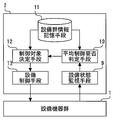
- FIG. 2 shows the configuration of the equipment control device applied to the building equipment management system shown in FIG.
- the equipment device group 1 shown in FIG. 2 represents one of the equipment devices group 1 (air conditioning equipment group 1a, lighting equipment group 1b) shown in FIG.
- the equipment device controller 2 shown in FIG. 2 is one of the equipment equipment controllers 2 (air conditioning equipment controller 2a, lighting equipment controller 2b) shown in FIG. This is representative.
- the equipment device controller 2 includes equipment state monitoring means 9, average control necessity determination means 10, equipment group information storage means 11, control object determination means 12, and equipment control means 13.
- the equipment state monitoring means 9 monitors the operating state of each of the plurality of equipment devices constituting the equipment device group 1. And it detects that the operating state of at least any one of the some installation apparatus which comprises the installation apparatus group 1 changed.
- each equipment apparatus air conditioning equipment and lighting equipment which comprises the equipment equipment group 1 (the air conditioning equipment group 1a and the lighting equipment group 1b) is a switch for changing the operating state. Etc. are provided. The user of the facility equipment can change the desired facility equipment constituting the equipment group 1 to a desired operating state by operating the operation means.
- the average control necessity determination means 10 is a facility that constitutes the equipment group 1 to which the equipment that has detected the change in the operating state belongs. Determine whether the device needs to be controlled. The determination as to whether or not this control is necessary is performed based on the average operating state of the equipment that constitutes the equipment group 1 to which the equipment that has detected a change in the operating state belongs.
- the equipment group information storage means 11 stores in advance a correspondence relationship to which equipment equipment group 1 each equipment installed in the building belongs.
- the average control necessity determination means 10 first refers to the correspondence stored in the equipment group information storage means 11, and the equipment to which the equipment whose operating state change is detected by the equipment status monitoring means 9 belongs. Group 1 is identified. Next, it is specified by referring to the correspondence stored in the facility group information storage means 11 which equipment is included in the specified equipment group 1. Then, based on the specified information, the operating state of each equipment device constituting the equipment device group 1 is acquired via the equipment state monitoring means 9.
- the average control necessity determination means 10 calculates the average of the acquired operating states of the respective facility devices, so that the facility devices constituting the facility device group 1 to which the facility devices in which the change in the operating state is detected belong. Find the average operating condition. Then, the average control necessity determination means 10 compares the average operating state thus obtained with a predetermined reference value, thereby determining the facility device group 1 to which the facility device in which the change in the operating state is detected belongs. It is determined whether or not the facility equipment to be configured needs to be controlled.
- the control target determining means 12 Determine the equipment to be controlled.
- the equipment to be controlled is selected from the equipment constituting the equipment group 1 to which the equipment whose operating state has been detected by the equipment state monitoring means 9 belongs. At this time, however, the equipment for which the change in the operating state is detected by the equipment state monitoring means 9 is excluded from the target.
- the priority order of the equipment to be determined as a control target may be determined in advance and stored in the equipment group information storage unit 11.
- the priority order of the air conditioning equipment determined as the control target may be determined by the measured value of the indoor thermometer. Furthermore, in the case of the lighting equipment group 1b, the priority order of the lighting equipment determined as the control target may be determined based on the measurement value of the indoor illuminometer.
- the facility control means 13 controls the operating state of the equipment in the equipment group 1 determined as the control target by the control target determination means 12. As a result of this control, the operation state control is such that the average operation state of each facility device constituting the facility device group 1 conforms to the reference value used for determination by the average control necessity determination means 10. It is done to become.
- the control of the equipment by the equipment control means 13 may be achieved, for example, by outputting a control signal, or may be achieved by opening / closing a contact such as a relay.
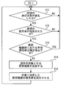
- the control device for equipment operates according to a series of flows shown in FIG.
- the equipment group 1 is the lighting equipment group 1b
- the operating state of the facility equipment group 1 is the lighting state of the lighting equipment group 1b
- the average of the equipment constituting the equipment device group 1 used for determination by the average control necessity determination unit 10 is used.
- a typical operating state is the lighting rate of the lighting equipment which comprises the lighting equipment group 1b.
- step S1 the equipment state monitoring means 9 confirms whether or not the lighting state of the lighting equipment of the lighting equipment group 1b has changed.
- the process proceeds to the next step S2.
- step S2 it is confirmed whether or not the change in the lighting state of the lighting equipment in step S1 is lighting of the lighting equipment.
- the process proceeds to step S3.
- the change in the lighting state of the lighting equipment is not lighting of the lighting equipment but off, the process returns to step S1.
- step S3 the average control necessity determination means 10 confirms whether or not the number of lighting fixtures constituting the lighting fixture group 1b to which the lighting fixture whose lighting state has changed in step S1 belongs is equal to or less than a specified value.
- the specified value can be calculated by multiplying the reference lighting rate by the total number of lighting equipments constituting the focused lighting equipment group 1b. Specifically, for example, when the lighting rate as a reference is 80% and the lighting equipment group 1b of interest is composed of 50 lighting equipments, the specified value is 40.
- step S3 if the number of lighting of the lighting equipment constituting the focused lighting equipment group 1b is equal to or less than a specified value, the lighting rate of the lighting equipment constituting the focused lighting equipment group 1b is set as a reference lighting. Since it is less than the rate, the process returns to step S1. On the other hand, in step S3, when the lighting number of the lighting equipment which comprises the focused lighting equipment group 1b exceeds the regulation value, it progresses to step S4.
- step S4 the control object determining means 12 determines the lighting equipment to be turned off from the lighting equipment group 1b of interest. At this time, the lighting equipment in which the change in the lighting state is detected in step S1 is excluded from the control target. By doing in this way, the situation where the lighting installation turned on by the user will be automatically turned off immediately after that can be avoided.
- step S4 the process proceeds to step S5.
- step S5 the equipment control means 13 turns off the lighting equipment determined as the target of the turn-off control in step S4.
- step S5 the process returns to step S1.
- the lighting rate in the lighting equipment group 1b is regularly checked every time a certain time elapses. Confirmation may be performed.
- the equipment control apparatus configured as described above includes a monitoring unit that detects that the operating state of at least one of a plurality of equipment constituting the equipment group has changed, and the equipment by the monitoring means.
- the facility device group is configured based on the average operating state of each facility device that configures the facility device group to which the facility device in which the change in the operating state is detected belongs.
- Necessity determining means for determining the necessity of control of the equipment and the equipment constituting the equipment apparatus group when the necessity determining means determines that the control of the equipment constituting the equipment apparatus group is necessary.
- the devices there are a control target determining means for determining a control target from equipment other than the equipment whose operating state is detected by the monitoring means, and a control target equipment determined by the control target determining means.
- Gosuru control means is those with.
- each facility device is maintained without pre-setting the control conditions for each facility device, while keeping the power consumption of the entire facility device group within the specified range. Accordingly, it is possible to automatically perform control so that a facility device required by the user is operated and an unnecessary configuration device is not operated.
- FIG. FIG. 4 is a flowchart according to Embodiment 2 of the present invention and showing the operation of the control device for equipment.
- the equipment is controlled so that the average operating state of each equipment constituting the equipment group meets a predetermined standard. there were.
- the installation apparatus was lighting equipment, and the example which made the average operation state which is the reference
- the equipment when the operating state of the equipment is changed, the equipment is controlled so that the average operating state of each equipment constituting the equipment group meets a predetermined standard.
- a predetermined standard As an example of the above, an example will be described in which the equipment is lighting equipment, and the average operating state, which is a reference for control, is the average dimming rate of the lighting equipment.
- step S11 of FIG. 4 the equipment state monitoring means 9 confirms whether or not the lighting state of the lighting equipment of the lighting equipment group 1b has changed.
- the process proceeds to the next step S12.
- step S12 it is confirmed whether or not the change in the lighting state of the lighting equipment in step S11 is an increase in the dimming rate of the lighting equipment. If the change in the lighting state of the lighting equipment is an increase in the dimming rate of the lighting equipment, the process proceeds to step S13.
- the change in the lighting state of the lighting equipment is not an increase in the dimming rate of the lighting equipment but a decrease, the process returns to step S11.
- step S13 the average control necessity determination means 10 determines whether or not the average dimming rate of the lighting equipment constituting the lighting equipment group 1b to which the lighting equipment whose lighting state has changed in step S11 is equal to or less than a specified value. Check.
- step S13 if the average dimming rate of the lighting equipment constituting the lighting equipment group 1b of interest is not more than the specified value, the process returns to step S11. On the other hand, when the average dimming rate of the lighting equipment constituting the lighting equipment group 1b of interest exceeds the specified value, the process proceeds to step S14.
- step S14 the control target determining means 12 determines the lighting equipment that is subject to dimming control from the lighting equipment group 1b of interest. At this time, the lighting equipment in which the change in the lighting state is detected in step S11 is excluded from the control target.
- step S15 the equipment control means 13 reduces the lighting equipment determined as the dimming control target in step S14 so that the average dimming rate in the lighting equipment group 1b of interest is below a specified value. Shine. After step S15, the process returns to step S11.
- the same effects as in the first embodiment can be obtained.
- This will be specifically described with reference to the example described in the second embodiment.
- the dimming rate of the lighting equipment is increased by the user's operation and the average dimming rate in the lighting equipment group exceeds 50%, the lighting equipment other than the lighting equipment for which the dimming rate has been increased immediately before The dimming rate of the lighting equipment is automatically reduced.
- the average dimming rate of the lighting equipment is suppressed to 50% or less, depending on the situation at that time. It is possible to automatically control to the state where the dimming rate necessary for each lighting equipment is obtained.
- the control of the operating state of the lighting equipment has been described as an example.
- the present invention can be similarly applied to other equipment other than the lighting equipment. it can.
- air conditioning equipment it is conceivable to automatically control the on / off state of operation, switching between cooling or heating operation and air blowing operation, the adjustment state of air volume during operation, and the like.
- FIG. FIG. 5 relates to Embodiment 3 of the present invention and is a flowchart showing the operation of the control device for equipment.
- the facility device when the operating state of the facility device changes, the facility device is configured so that the average operating state of each facility device constituting the facility device group conforms to a predetermined standard. Was to control.
- the control target value of the equipment when the control target value of the equipment is changed, the average control target value of each equipment constituting the equipment group is adapted to a predetermined standard.
- the control target value of the equipment is controlled.
- the equipment is an air conditioning facility
- an average control target value that is a reference for control is an average value of the set temperature of the air conditioning facility.
- the equipment device controller 2 includes equipment state monitoring means 9, average control necessity determination means 10, equipment group information storage means 11, control object determination means 12, and equipment control means 13.
- the equipment state monitoring means 9 monitors the control target value set for each of the plurality of equipment devices constituting the equipment device group 1. And it detects that the control target value of at least any one of the some installation apparatus which comprises the installation apparatus group 1 changed.
- each equipment apparatus air conditioning equipment and lighting equipment which comprises the equipment equipment group 1 (air conditioning equipment group 1a and lighting equipment group 1b) changes the setting of the control target value.
- An operation means such as a switch is provided. The user of the equipment can change the control target value of the desired equipment constituting the equipment group 1 to a desired one by operating the operation means.
- the average control necessity determination means 10 constitutes the equipment device group 1 to which the equipment device in which the change in the control target value is detected belongs. It is determined whether or not the control target value of the equipment to be changed needs to be changed. The determination as to whether or not the control target value needs to be changed is made based on the average value of the control target values of the facility devices that constitute the facility device group 1 to which the facility device in which the change in the control target value is detected belongs.
- the average control necessity determination means 10 first refers to the correspondence stored in the equipment group information storage means 11, and the equipment to which the equipment whose change in the control target value is detected by the equipment state monitoring means 9 belongs. Group 1 is identified. Next, it is specified by referring to the correspondence stored in the facility group information storage means 11 which equipment is included in the specified equipment group 1. And based on this specified information, the control target value of each facility apparatus which comprises the facility apparatus group 1 is acquired via the installation state monitoring means 9. FIG.
- the average control necessity determination means 10 calculates an average value of the acquired control target values of each facility device. Then, the average control necessity determination means 10 compares the average value of the control target values obtained in this way with a predetermined reference value, so that the equipment group to which the equipment whose change in the control target value is detected belongs. It is determined whether or not it is necessary to change the control target value for the equipment constituting 1.
- the average control necessity determination means 10 determines that it is necessary to change the control target value for the equipment constituting the equipment group 1 to which the equipment whose change in the control target value is detected belongs, the control target is determined.
- the means 12 determines the equipment for which the control target value is to be changed.
- the equipment for which the control target value is to be changed is selected from the equipment constituting the equipment group 1 to which the equipment whose change in the control target value is detected by the equipment state monitoring means 9 belongs. At this time, however, the equipment whose change in the control target value is detected by the equipment state monitoring means 9 is excluded from the target.
- the facility control unit 13 changes the control target value of the facility device of the facility device group 1 determined by the control target determination unit 12 as the target of the control target value change.
- the change of the control target value is such that the average value of the control target values of the respective equipment constituting the equipment group 1 conforms to the reference value used for the determination by the average control necessity determination means 10. To be done.
- the operation of the equipment control apparatus according to Embodiment 3 will be described with reference to FIG.
- the equipment group 1 is the air conditioning equipment group 1a and the control target value of the equipment equipment group 1 is the set temperature of the air conditioning equipment group 1a will be described.
- step S21 the equipment state monitoring means 9 confirms whether or not the set temperature of the air conditioning equipment constituting the air conditioning equipment group 1a has changed.
- the process proceeds to the next step S22.
- step S22 it is confirmed whether or not the change in the set temperature of the air conditioning equipment in step S21 is an increase in the set temperature.
- the process proceeds to step S23.
- the set temperature of the air conditioning equipment is not an increase but a decrease, the process returns to step S21.
- step S23 the average control necessity determination means 10 confirms whether or not the average set temperature of the air conditioning equipment constituting the air conditioning equipment group 1a to which the air conditioning equipment whose set temperature has changed in step S21 is equal to or less than a specified value. To do.
- step S23 if the average set temperature of the air-conditioning equipment constituting the air-conditioning equipment group 1a of interest is not more than the specified value, the process returns to step S21. On the other hand, when the average set temperature of the air conditioning equipment constituting the air conditioning equipment group 1a of interest exceeds the specified value, the process proceeds to step S24.
- step S24 the control target determining means 12 determines the air conditioning equipment that is the target of changing the set temperature from the air conditioning equipment group 1a of interest. At this time, the air conditioning equipment in which the change in the set temperature is detected in step S21 is excluded from the change target.
- step S24 the process proceeds to step S25.
- the facility control means 13 determines that the set temperature of the air conditioning equipment determined as the target of the set temperature change in step S24 is such that the average value of the set temperatures in the air conditioning facility group 1a of interest is not more than the specified value. Change to After step S25, the process returns to step S21.
- the equipment control device configured as described above includes a monitoring unit that detects that a control target value of at least one of a plurality of equipment constituting the equipment group has changed, and a facility by the monitoring unit.
- the facility device is determined based on the average value of the control target values of the facility devices that constitute the facility device group to which the facility device in which the change in the control target value is detected belongs.
- the necessity judgment means determines that the control of the equipment that constitutes the equipment apparatus group is necessary.
- Control object determination means for determining a target of change of the control target value from equipment other than the equipment whose change in the control target value is detected by the monitoring means among the equipment constituting the equipment group, and control target determination To the means And control means for changing the control target value of the determined control target equipment Ri are those having a.
- the power consumption of other equipment belonging to the equipment device group can be automatically controlled so as to reduce. Accordingly, it is possible to suppress an increase in the power consumption of the entire equipment group before and after the change of the control target value by the user.
- the example given here is an example of keeping the power consumption within the specified range by setting the average value of the set temperature to a reference value or less when performing heating operation in winter.
- the present invention can be used for, for example, a control device for equipment that controls the operating states and control target values of a plurality of equipment installed in a building or facility such as a building.
Abstract
Provided is a device that is for controlling facility equipment and that that can control facility equipment in a manner so as to have a suitable operational condition that is in accordance with the level of necessity of each piece of facility equipment, even without pre-setting control conditions or the like for each piece of facility equipment. Thus, the device for controlling facility equipment is provided with: a monitoring means that detects that the operational condition of a plurality of facility equipment configuring a facility equipment group has changed; a necessity determination means that, when a change in the operational condition of the facility equipment has been detected, determines the necessity of controlling the facility equipment configuring the facility equipment group on the basis of an average operational condition of each piece of facility equipment configuring the facility equipment group to which the piece of facility equipment for which a change in operational condition has been detected belongs; a control subject determination means that, when it has been determined that control of the facility equipment configuring the facility equipment group is necessary, determines a subject of control from the facility equipment aside from the piece of facility equipment for which a change in operation condition has been detected by the monitoring means among the facility equipment configuring the facility equipment group; and a control means that controls the piece of facility equipment that has been determined to be the subject of control.
Description
この発明は、設備機器の制御装置に関するものである。
This invention relates to a control device for equipment.
従来、ビルに設置されている空気調和装置や照明装置等の各種設備機器を監視・制御する設備機器の制御装置においては、各エリアの所在人数に基づいて、人がいるエリアの空調、照明の稼働を維持する一方で、無人のエリアの空調、照明の稼働を停止させることで、無駄な電力消費を抑制しようとするものが知られている(例えば、特許文献1参照)。
Conventionally, in equipment control devices that monitor and control various equipment such as air conditioners and lighting equipment installed in buildings, air conditioning and lighting in areas where people are present based on the number of people in each area. While maintaining operation, what is known is an attempt to suppress wasteful power consumption by stopping air conditioning and lighting operation in an unattended area (see, for example, Patent Document 1).
また、空調機器の冷暖房運転時に、室内温度を基準値と比較して過剰な冷暖房運転をしている状態の継続を違反時間としてカウントし、このカウント結果を表示することで過剰な冷暖房運転の改善を促してエネルギー消費量の削減を図ろうとするものも、従来において知られている(例えば、特許文献2参照)。
Also, during air conditioning operation of the air conditioning equipment, the room temperature is compared with the reference value, the continuation of the state of excessive air conditioning operation is counted as a violation time, and this count result is displayed to improve excessive air conditioning operation In the past, there has been known an attempt to reduce the energy consumption by promoting the above (see, for example, Patent Document 2).
さらに、複数のエリア毎に設置された照明機器を含む多数の受電設備を備えた施設に用いられるデマンド制御システムにおいて、受電設備の消費電力の積算値であるデマンド値が予め設定された契約電力量を超過することが予測された場合には、複数のエリア毎に設置された照明機器のうち、いずれの照明機器を制御対象とするかを選択するとともにその制御条件を規定するデマンドスケジュールに従って照明機器を制御するものも従来において知られている(例えば、特許文献3参照)。
Furthermore, in a demand control system used in a facility having a large number of power receiving facilities including lighting equipment installed in a plurality of areas, a contract power amount in which a demand value that is an integrated value of the power consumption of the power receiving facility is preset. If it is predicted that the lighting device will exceed the lighting device, the lighting device is selected according to the demand schedule that defines which lighting device is to be controlled from among the lighting devices installed in each of the plurality of areas and defines the control conditions. A device that controls the above is also known in the art (see, for example, Patent Document 3).
しかしながら、特許文献1に示された従来における設備機器の制御装置においては、エリア毎の人の入退場状況を監視して各エリアの所在人数を判断する入退室管理システムを備えていることが前提である。このため、システムの規模が大きくなりシステムの構成費用がかさんでしまうという課題がある。また、設備機器の運転を所在人数のみに基づいて判断するため、人がいなくとも稼働させることが必要な場合や逆に人がいても稼働させる必要がない場合等において、適切な制御を行うことができないという課題がある。
However, it is assumed that the conventional equipment control apparatus shown in Patent Document 1 includes an entrance / exit management system that monitors the entrance / exit status of people in each area and determines the number of people in each area. It is. For this reason, there exists a subject that the scale of a system becomes large and the structure cost of a system will be increased. In addition, since the operation of equipment is determined based only on the number of people in the location, appropriate control should be performed in cases where it is necessary to operate without a person or vice versa. There is a problem that cannot be done.
特許文献2に示された従来における設備機器の制御装置は、利用者に過剰な冷暖房運転の改善を促すのみであって、空調機器の運転の制御を行うものではない。このため、過剰な冷暖房運転を改善するか否かは利用者の判断に委ねられ、規定された電力消費量を必ずしも守ることができないという課題がある。
The conventional equipment control apparatus shown in Patent Document 2 only prompts the user to improve excessive cooling and heating operation, and does not control the operation of the air conditioning equipment. For this reason, it is left to a user's judgment whether to improve excessive air-conditioning operation, and there exists a subject that the prescribed electric power consumption cannot always be protected.
そして、特許文献3に示された従来における設備機器の制御装置においては、予め、個々の照明機器について、制御対象として選択される条件と、制御対象として選択された場合の制御内容とを詳しく設定しておかねばならず、繁雑である。また、予め制御条件等を設定した際に想定した状況とは異なる状況が発生した場合に、適切な制御を行うことができない。また、電力使用量を用いて制御の要否等を判断する場合、電力使用量を計測する機器が必要である。
And in the control apparatus of the conventional equipment shown by patent document 3, the conditions selected as a control object and the control content at the time of being selected as a control object are set in detail about each lighting apparatus beforehand. It must be kept complicated. In addition, when a situation different from the situation assumed when the control conditions are set in advance, appropriate control cannot be performed. In addition, when determining the necessity of control using the power usage amount, a device for measuring the power usage amount is required.
この発明は、このような課題を解決するためになされたもので、個々の設備機器の全てについて制御条件や制御内容を予め設定する必要がなく、設備機器群の全体での電力消費量を規定された範囲内に保ったまま、各設備機器の必要度に応じた適切な状態となるように設備機器を制御することができる設備機器の制御装置を得るものである。
The present invention has been made to solve such a problem, and it is not necessary to preset control conditions and control contents for all of the individual equipment and prescribes the power consumption of the entire equipment equipment group. Thus, a control device for facility equipment that can control the facility equipment so as to be in an appropriate state according to the degree of necessity of each facility equipment while being kept within the specified range is obtained.
この発明に係る設備機器の制御装置においては、設備機器群を構成する複数の設備機器のうちの少なくともいずれか一の稼働状態が変化したことを検出する監視手段と、前記監視手段により設備機器の稼働状態の変化が検出された場合に、稼働状態の変化が検出された設備機器が属する設備機器群を構成する各設備機器の平均的な稼働状態に基づいて、当該設備機器群を構成する設備機器の制御の要否を判定する要否判定手段と、前記要否判定手段により設備機器群を構成する設備機器の制御が必要であると判定された場合に、当該設備機器群を構成する設備機器のうち、前記監視手段により稼働状態の変化が検出された設備機器以外の設備機器から制御の対象を決定する制御対象決定手段と、前記制御対象決定手段により決定された制御対象の設備機器を制御する制御手段と、を備えた構成とする。
In the equipment control apparatus according to the present invention, the monitoring means for detecting that the operating state of at least any one of the plurality of equipment constituting the equipment group has changed, and the monitoring means When a change in the operating state is detected, the equipment that configures the equipment group based on the average operating state of each equipment that constitutes the equipment group to which the equipment that has detected the change in the operating state belongs. Necessity determining means for determining necessity of control of equipment, and facilities constituting the equipment group when it is determined by the necessity determining means that control of the equipment constituting the equipment group is necessary. Among the devices, control target determining means for determining a control target from equipment other than the equipment whose operating state is detected by the monitoring means, and control determined by the control target determining means And configured to include a control means for controlling the elephant equipment, the.
また、設備機器群を構成する複数の設備機器のうちの少なくともいずれか一の制御目標値が変化したことを検出する監視手段と、前記監視手段により設備機器の制御目標値の変化が検出された場合に、制御目標値の変化が検出された設備機器が属する設備機器群を構成する各設備機器の制御目標値の平均値に基づいて、当該設備機器群を構成する設備機器の制御目標値の変更の要否を判定する要否判定手段と、前記要否判定手段により設備機器群を構成する設備機器の制御が必要であると判定された場合に、当該設備機器群を構成する設備機器のうち、前記監視手段により制御目標値の変化が検出された設備機器以外の設備機器から制御目標値の変更の対象を決定する制御対象決定手段と、前記制御対象決定手段により決定された制御対象の設備機器の制御目標値を変更する制御手段と、を備えた構成とする。
Moreover, the monitoring means for detecting that the control target value of at least one of the plurality of equipment constituting the equipment group has changed, and the change in the control target value of the equipment is detected by the monitoring means. In this case, based on the average value of the control target values of each equipment device that constitutes the equipment device group to which the equipment device in which the change of the control target value is detected belongs, the control target value of the equipment device that constitutes the equipment device group Necessity determining means for determining necessity of change, and when it is determined by the necessity determining means that control of the equipment constituting the equipment apparatus group is necessary, the equipment equipment constituting the equipment equipment group Among these, the control target determining means for determining the target of the change of the control target value from the equipment other than the equipment whose change in the control target value is detected by the monitoring means, and the control target determined by the control target determining means And control means for changing the control target value of the equipment, the configuration with.
この発明に係る設備機器の制御装置においては、個々の設備機器の全てについて制御条件や制御内容を予め設定することなく、各設備機器の必要度に応じた適切な状態となるように設備機器を制御することができるという効果を奏する。
In the control device for equipment according to the present invention, the equipment is set so as to be in an appropriate state according to the degree of necessity of each equipment without setting control conditions and control contents in advance for all the equipment. There is an effect that it can be controlled.
この発明を添付の図面に従い説明する。各図を通じて同符号は同一部分又は相当部分を示しており、その重複説明は適宜に簡略化又は省略する。
The present invention will be described with reference to the accompanying drawings. Throughout the drawings, the same reference numerals indicate the same or corresponding parts, and redundant description thereof will be simplified or omitted as appropriate.
実施の形態1.
図1から図3は、この発明の実施の形態1に係るもので、図1は設備機器の制御装置が適用されるビル設備管理システムの構成を示す図、図2は設備機器の制御装置の構成を示す図、図3は設備機器の制御装置の動作を示すフロー図である。Embodiment 1 FIG.
FIGS. 1 to 3 relate toEmbodiment 1 of the present invention. FIG. 1 is a diagram showing a configuration of a building equipment management system to which a control device for equipment is applied, and FIG. FIG. 3 is a flowchart showing the operation of the control device for equipment.
図1から図3は、この発明の実施の形態1に係るもので、図1は設備機器の制御装置が適用されるビル設備管理システムの構成を示す図、図2は設備機器の制御装置の構成を示す図、図3は設備機器の制御装置の動作を示すフロー図である。
FIGS. 1 to 3 relate to
図1において、1は、ビルに設置された設備機器群である。1つの設備機器群1は、複数の同種の設備機器から構成されている。具体的に例えば、設備機器群1には、空調設備群1aや照明設備群1bが含まれている。ある1つの空調設備群1aは、当該ビル内に設置された複数の空気調和装置から構成される。また、ある1つの照明設備群1bは、当該ビル内に設置された複数の照明設備から構成される。
In FIG. 1, 1 is a group of equipment installed in the building. One equipment group 1 is composed of a plurality of the same kind of equipment. Specifically, for example, the equipment group 1 includes an air conditioning equipment group 1a and a lighting equipment group 1b. One certain air conditioning equipment group 1a is composed of a plurality of air conditioners installed in the building. Moreover, one certain lighting equipment group 1b is comprised from the several lighting equipment installed in the said building.
ある一種の設備機器についての設備機器群は、複数存在することができる。例えば空調設備群1aは1つだけでなく複数設定されていてもよいし、照明設備群1bについても1つだけでなく複数設定されていてもよい。この際、設備機器群は、例えば設備機器が設置されている部屋、エリアやフロア等に基づいて区分される。
There can be a plurality of equipment groups for a certain kind of equipment. For example, not only one air conditioning equipment group 1a but also a plurality of lighting equipment groups 1b may be set, and not only one lighting equipment group 1b but also a plurality may be set. At this time, the equipment group is classified based on, for example, a room, an area, a floor, or the like where the equipment is installed.
設備機器群1の稼働状態は、設備機器用コントローラ2により制御される。具体的に例えば、空調設備群1aは空調設備用コントローラ2aにより制御される。また、照明設備群1bは照明設備用コントローラ2bにより制御される。この設備機器用コントローラ2は、各設備機器群1につき1つずつ設けられる。なお、設備機器用コントローラ2は、設備機器群1の稼働状態を制御する機能の他、各設備機器群1の稼働状態を取得して監視する機能も備えている。
The operating state of the equipment group 1 is controlled by the equipment controller 2. Specifically, for example, the air conditioning equipment group 1a is controlled by the air conditioning equipment controller 2a. The lighting equipment group 1b is controlled by a lighting equipment controller 2b. One equipment device controller 2 is provided for each equipment device group 1. The equipment device controller 2 has a function of acquiring and monitoring the operating state of each equipment device group 1 in addition to the function of controlling the operating state of the equipment device group 1.
これらの設備機器群1(空調設備群1aや照明設備群1b)の稼働運転に必要な電力を受電するため、ビルには受変電設備3が設けられている。この受変電設備3は、ビルの外部からの電力を受電し、設備機器群1で使用するのに必要な例えば降圧等の変電を行うものである。この受変電設備3の動作状態の監視や制御は、受変電設備用コントローラ4により行われる。
In order to receive power necessary for the operation of these equipment group 1 (air conditioning equipment group 1a and lighting equipment group 1b), a receiving and transforming equipment 3 is provided in the building. The power receiving / transforming equipment 3 receives electric power from outside the building and performs power transformation such as step-down necessary for use in the equipment group 1. Monitoring and control of the operating state of the power receiving / transforming equipment 3 is performed by the power receiving / transforming equipment controller 4.
また、ビルには、設備機器群1へと供給された電力量を計測する電力計測器5が設けられている。この電力計測器5により計測された電力量は、電力計測器用コントローラ6により監視される。
Also, the building is provided with a power measuring instrument 5 that measures the amount of power supplied to the equipment group 1. The amount of power measured by the power meter 5 is monitored by the power meter controller 6.
設備機器用コントローラ2(空調設備用コントローラ2aや照明設備用コントローラ2b)、受変電設備用コントローラ4及び電力計測器用コントローラ6のそれぞれは、通信ネットワーク8を介してサーバ7と通信可能に接続されている。このサーバ7は、例えばビル内の管理人室等に設置されている。サーバ7には、ビル設備管理システムの監視・操作画面が表示される。ビル設備の管理者は、サーバ7の監視・操作画面を通じて、設備機器群1の状態や異常の監視及び設備機器群1の運転制御設定等を行うことができる。
Each of the equipment device controller 2 (air conditioning equipment controller 2a and lighting equipment controller 2b), power receiving / transformation equipment controller 4 and power meter controller 6 is connected to the server 7 via the communication network 8 so as to be communicable. Yes. This server 7 is installed, for example, in a manager room in a building. The server 7 displays a building facility management system monitoring / operation screen. The manager of the building facility can monitor the state and abnormality of the facility device group 1 and set the operation control of the facility device group 1 through the monitoring / operation screen of the server 7.
なお、設備機器用コントローラ2、受変電設備用コントローラ4及び電力計測器用コントローラ6は、ビル内の電気パイプスペースに設置される。ただし、設備機器用コントローラ2、特に空調設備用コントローラ2aは、ビル内のフロア毎に壁に埋め込まれたり天井裏に設置されたりする場合もある。
The equipment device controller 2, the substation equipment controller 4 and the power meter controller 6 are installed in an electric pipe space in the building. However, the equipment device controller 2, particularly the air conditioning equipment controller 2 a, may be embedded in the wall or installed behind the ceiling for each floor in the building.
図2に、図1で示したビル設備管理システムに適用された設備機器の制御装置の構成を示す。この図2に示す設備機器群1は、図1で示した設備機器群1(空調設備群1a、照明設備群1b)のうちの1つを代表して表すものである。また、設備機器用コントローラ2についても同様で、図2に示す設備機器用コントローラ2は、図1で示した設備機器用コントローラ2(空調設備用コントローラ2a、照明設備用コントローラ2b)のうちの1つを代表して示すものである。
FIG. 2 shows the configuration of the equipment control device applied to the building equipment management system shown in FIG. The equipment device group 1 shown in FIG. 2 represents one of the equipment devices group 1 (air conditioning equipment group 1a, lighting equipment group 1b) shown in FIG. The same applies to the equipment device controller 2, and the equipment device controller 2 shown in FIG. 2 is one of the equipment equipment controllers 2 (air conditioning equipment controller 2a, lighting equipment controller 2b) shown in FIG. This is representative.
設備機器用コントローラ2は、設備状態監視手段9、平均制御要否判定手段10、設備群情報記憶手段11、制御対象決定手段12及び設備制御手段13を備えている。
設備状態監視手段9は、設備機器群1を構成する複数の設備機器それぞれの稼働状態を監視している。そして、設備機器群1を構成する複数の設備機器のうちの少なくともいずれか一の稼働状態が変化したことを検出する。 Theequipment device controller 2 includes equipment state monitoring means 9, average control necessity determination means 10, equipment group information storage means 11, control object determination means 12, and equipment control means 13.
The equipment state monitoring means 9 monitors the operating state of each of the plurality of equipment devices constituting theequipment device group 1. And it detects that the operating state of at least any one of the some installation apparatus which comprises the installation apparatus group 1 changed.
設備状態監視手段9は、設備機器群1を構成する複数の設備機器それぞれの稼働状態を監視している。そして、設備機器群1を構成する複数の設備機器のうちの少なくともいずれか一の稼働状態が変化したことを検出する。 The
The equipment state monitoring means 9 monitors the operating state of each of the plurality of equipment devices constituting the
なお、ここでは図示を省略しているが、設備機器群1(空調設備群1aや照明設備群1b)を構成する各設備機器(空調設備や照明設備)は、その稼働状態を変えるためのスイッチ等の操作手段が設けられている。設備機器の利用者は、操作手段を操作することによって、設備機器群1を構成する所望の設備機器を所望の稼働状態へと変えることができる。
In addition, although illustration is abbreviate | omitted here, each equipment apparatus (air conditioning equipment and lighting equipment) which comprises the equipment equipment group 1 (the air conditioning equipment group 1a and the lighting equipment group 1b) is a switch for changing the operating state. Etc. are provided. The user of the facility equipment can change the desired facility equipment constituting the equipment group 1 to a desired operating state by operating the operation means.
平均制御要否判定手段10は、設備状態監視手段9により設備機器の稼働状態の変化が検出された場合に、この稼働状態の変化が検出された設備機器が属する設備機器群1を構成する設備機器の制御の必要があるか否かを判定する。この制御の要否の判定は、稼働状態の変化が検出された設備機器が属する設備機器群1を構成する設備機器の平均的な稼働状態に基づいて行われる。
When the equipment state monitoring means 9 detects a change in the operating state of the equipment, the average control necessity determination means 10 is a facility that constitutes the equipment group 1 to which the equipment that has detected the change in the operating state belongs. Determine whether the device needs to be controlled. The determination as to whether or not this control is necessary is performed based on the average operating state of the equipment that constitutes the equipment group 1 to which the equipment that has detected a change in the operating state belongs.
設備群情報記憶手段11には、ビル内に設置されたそれぞれの設備機器がどの設備機器群1に属するのかの対応関係が、予め記憶されている。平均制御要否判定手段10は、まず、この設備群情報記憶手段11に記憶された対応関係を参照し、設備状態監視手段9により稼働状態の変化が検出された設備機器が属している設備機器群1を特定する。次に、この特定した設備機器群1を構成する設備機器がどれであるのかを設備群情報記憶手段11に記憶された対応関係を参照して特定する。そして、この特定した情報をもとに、設備機器群1を構成する各設備機器の稼働状態を設備状態監視手段9を介して取得する。
The equipment group information storage means 11 stores in advance a correspondence relationship to which equipment equipment group 1 each equipment installed in the building belongs. The average control necessity determination means 10 first refers to the correspondence stored in the equipment group information storage means 11, and the equipment to which the equipment whose operating state change is detected by the equipment status monitoring means 9 belongs. Group 1 is identified. Next, it is specified by referring to the correspondence stored in the facility group information storage means 11 which equipment is included in the specified equipment group 1. Then, based on the specified information, the operating state of each equipment device constituting the equipment device group 1 is acquired via the equipment state monitoring means 9.
続いて、平均制御要否判定手段10は、取得した各設備機器の稼働状態の平均を算出することで、稼働状態の変化が検出された設備機器が属する設備機器群1を構成する設備機器の平均的な稼働状態を求める。そして、平均制御要否判定手段10は、こうして求めた平均的な稼働状態を、予め定められた基準値と比較することにより、稼働状態の変化が検出された設備機器が属する設備機器群1を構成する設備機器について制御の必要があるか否かを判定する。
Subsequently, the average control necessity determination means 10 calculates the average of the acquired operating states of the respective facility devices, so that the facility devices constituting the facility device group 1 to which the facility devices in which the change in the operating state is detected belong. Find the average operating condition. Then, the average control necessity determination means 10 compares the average operating state thus obtained with a predetermined reference value, thereby determining the facility device group 1 to which the facility device in which the change in the operating state is detected belongs. It is determined whether or not the facility equipment to be configured needs to be controlled.
平均制御要否判定手段10により、稼働状態の変化が検出された設備機器が属する設備機器群1を構成する設備機器について制御する必要があると判断されると、制御対象決定手段12は、この制御の対象となる設備機器を決定する。
When the average control necessity determination means 10 determines that it is necessary to control the equipment constituting the equipment group 1 to which the equipment in which the change in the operating state is detected belongs, the control target determining means 12 Determine the equipment to be controlled.
この制御の対象となる設備機器は、設備状態監視手段9により稼働状態の変化が検出された設備機器が属する設備機器群1を構成する設備機器のうちから選択される。ただし、この際、設備状態監視手段9により稼働状態の変化が検出された設備機器は対象から除かれる。なお、ここで、制御の対象として決定される設備機器の優先順位を予め定めておき、設備群情報記憶手段11に記憶させておいてもよい。
The equipment to be controlled is selected from the equipment constituting the equipment group 1 to which the equipment whose operating state has been detected by the equipment state monitoring means 9 belongs. At this time, however, the equipment for which the change in the operating state is detected by the equipment state monitoring means 9 is excluded from the target. Here, the priority order of the equipment to be determined as a control target may be determined in advance and stored in the equipment group information storage unit 11.
また、空調設備群1aの場合には室内の温度計の計測値により制御の対象として決定される空調設備の優先順位を決めるようにしてもよい。さらにまた、照明設備群1bの場合には室内の照度計の計測値により制御の対象として決定される照明設備の優先順位を決めるようにしてもよい。
In the case of the air conditioning equipment group 1a, the priority order of the air conditioning equipment determined as the control target may be determined by the measured value of the indoor thermometer. Furthermore, in the case of the lighting equipment group 1b, the priority order of the lighting equipment determined as the control target may be determined based on the measurement value of the indoor illuminometer.
設備制御手段13は、制御対象決定手段12により制御対象に決定された設備機器群1の設備機器の稼働状態を制御する。この稼働状態の制御は、この制御の結果、設備機器群1を構成する各設備機器の平均的な稼働状態が、平均制御要否判定手段10での判定に用いられた基準値に適合するものとなるように行われる。設備制御手段13による設備機器の制御は、例えば、制御信号を出力することにより達成されるものであってもよいし、リレー等の接点を開閉することにより達成されるものであってもよい。
The facility control means 13 controls the operating state of the equipment in the equipment group 1 determined as the control target by the control target determination means 12. As a result of this control, the operation state control is such that the average operation state of each facility device constituting the facility device group 1 conforms to the reference value used for determination by the average control necessity determination means 10. It is done to become. The control of the equipment by the equipment control means 13 may be achieved, for example, by outputting a control signal, or may be achieved by opening / closing a contact such as a relay.
この実施の形態にあっては、設備機器の制御装置は、図3に示す一連のフローに従って動作する。
この図3においては、設備機器群1が照明設備群1bである場合について説明する。ここで説明する例では、設備機器群1の稼働状態とは照明設備群1bの点灯状態であり、平均制御要否判定手段10での判定に用いられる設備機器群1を構成する設備機器の平均的な稼働状態とは、照明設備群1bを構成する照明設備の点灯率である。 In this embodiment, the control device for equipment operates according to a series of flows shown in FIG.
In FIG. 3, the case where theequipment group 1 is the lighting equipment group 1b will be described. In the example described here, the operating state of the facility equipment group 1 is the lighting state of the lighting equipment group 1b, and the average of the equipment constituting the equipment device group 1 used for determination by the average control necessity determination unit 10 is used. A typical operating state is the lighting rate of the lighting equipment which comprises the lighting equipment group 1b.
この図3においては、設備機器群1が照明設備群1bである場合について説明する。ここで説明する例では、設備機器群1の稼働状態とは照明設備群1bの点灯状態であり、平均制御要否判定手段10での判定に用いられる設備機器群1を構成する設備機器の平均的な稼働状態とは、照明設備群1bを構成する照明設備の点灯率である。 In this embodiment, the control device for equipment operates according to a series of flows shown in FIG.
In FIG. 3, the case where the
まず、ステップS1において、設備状態監視手段9は、照明設備群1bの照明設備の点灯状態が変化したか否かを確認する。照明設備の点灯状態が変化した場合は次のステップS2へと進む。ステップS2においては、ステップS1での照明設備の点灯状態の変化が照明設備の点灯であるか否かを確認する。照明設備の点灯状態の変化が照明設備の消灯ではなく点灯であった場合にはステップS3へと進む。一方、照明設備の点灯状態の変化が照明設備の点灯ではなく消灯であった場合にはステップS1へと戻る。
First, in step S1, the equipment state monitoring means 9 confirms whether or not the lighting state of the lighting equipment of the lighting equipment group 1b has changed. When the lighting state of the lighting equipment has changed, the process proceeds to the next step S2. In step S2, it is confirmed whether or not the change in the lighting state of the lighting equipment in step S1 is lighting of the lighting equipment. When the change in the lighting state of the lighting equipment is not lighting off but lighting, the process proceeds to step S3. On the other hand, when the change in the lighting state of the lighting equipment is not lighting of the lighting equipment but off, the process returns to step S1.
ステップS3においては、平均制御要否判定手段10は、ステップS1で点灯状態が変化した照明設備が属する照明設備群1bを構成する照明設備の点灯数が規定値以下であるか否かを確認する。ここでの規定値は、基準とする点灯率に、注目している照明設備群1bを構成する照明設備の総数を乗じることにより算出することができる。具体的に例えば、基準とする点灯率が80%であり、注目している照明設備群1bが50台の照明設備から構成されている場合、前記規定値は40台となる。
In step S3, the average control necessity determination means 10 confirms whether or not the number of lighting fixtures constituting the lighting fixture group 1b to which the lighting fixture whose lighting state has changed in step S1 belongs is equal to or less than a specified value. . Here, the specified value can be calculated by multiplying the reference lighting rate by the total number of lighting equipments constituting the focused lighting equipment group 1b. Specifically, for example, when the lighting rate as a reference is 80% and the lighting equipment group 1b of interest is composed of 50 lighting equipments, the specified value is 40.
このステップS3において、注目している照明設備群1bを構成する照明設備の点灯数が規定値以下であれば、注目している照明設備群1bを構成する照明設備の点灯率は基準とする点灯率以下ということになるため、ステップS1へと戻る。一方、ステップS3において、注目している照明設備群1bを構成する照明設備の点灯数が規定値を超えている場合には、ステップS4へと進む。
In this step S3, if the number of lighting of the lighting equipment constituting the focused lighting equipment group 1b is equal to or less than a specified value, the lighting rate of the lighting equipment constituting the focused lighting equipment group 1b is set as a reference lighting. Since it is less than the rate, the process returns to step S1. On the other hand, in step S3, when the lighting number of the lighting equipment which comprises the focused lighting equipment group 1b exceeds the regulation value, it progresses to step S4.
このステップS4においては、制御対象決定手段12は、注目している照明設備群1bのうちから消灯制御の対象となる照明設備を決定する。この際、ステップS1で点灯状態の変化が検出された照明設備は制御対象から除かれる。このようにすることで、利用者により点灯された照明設備が、その直後に自動的に消灯されてしまう事態を避けることができる。
In this step S4, the control object determining means 12 determines the lighting equipment to be turned off from the lighting equipment group 1b of interest. At this time, the lighting equipment in which the change in the lighting state is detected in step S1 is excluded from the control target. By doing in this way, the situation where the lighting installation turned on by the user will be automatically turned off immediately after that can be avoided.
ステップS4の後はステップS5へと進む。このステップS5においては、設備制御手段13は、ステップS4で消灯制御の対象に決定された照明設備を消灯する。ステップS5の後はステップS1へと戻る。
After step S4, the process proceeds to step S5. In this step S5, the equipment control means 13 turns off the lighting equipment determined as the target of the turn-off control in step S4. After step S5, the process returns to step S1.
なお、ここで説明したように照明設備のいずれかが点灯されたら照明設備群1bにおける点灯率を確認することに加えて、一定時間が経過する毎に定期的に照明設備群1bにおける点灯率の確認を行うようにしてもよい。
In addition to confirming the lighting rate in the lighting equipment group 1b when any one of the lighting equipments is turned on as described here, the lighting rate in the lighting equipment group 1b is regularly checked every time a certain time elapses. Confirmation may be performed.
以上のように構成された設備機器の制御装置は、設備機器群を構成する複数の設備機器のうちの少なくともいずれか一の稼働状態が変化したことを検出する監視手段と、監視手段により設備機器の稼働状態の変化が検出された場合に、稼働状態の変化が検出された設備機器が属する設備機器群を構成する各設備機器の平均的な稼働状態に基づいて、当該設備機器群を構成する設備機器の制御の要否を判定する要否判定手段と、要否判定手段により設備機器群を構成する設備機器の制御が必要であると判定された場合に、当該設備機器群を構成する設備機器のうち、監視手段により稼働状態の変化が検出された設備機器以外の設備機器から制御の対象を決定する制御対象決定手段と、制御対象決定手段により決定された制御対象の設備機器を制御する制御手段と、を備えたものである。
The equipment control apparatus configured as described above includes a monitoring unit that detects that the operating state of at least one of a plurality of equipment constituting the equipment group has changed, and the equipment by the monitoring means. When a change in the operating state is detected, the facility device group is configured based on the average operating state of each facility device that configures the facility device group to which the facility device in which the change in the operating state is detected belongs. Necessity determining means for determining the necessity of control of the equipment and the equipment constituting the equipment apparatus group when the necessity determining means determines that the control of the equipment constituting the equipment apparatus group is necessary. Among the devices, there are a control target determining means for determining a control target from equipment other than the equipment whose operating state is detected by the monitoring means, and a control target equipment determined by the control target determining means. And Gosuru control means is those with.
このため、設備機器群を構成するある設備機器について、電力消費量が増加するような操作が利用者によりなされた場合に、当該設備機器群に属する他の設備機器における電力消費量を低減するように自動的に制御することができる。また、したがって、利用者による操作の前後における当該設備機器群の全体での電力消費量の増加を抑制することができる。
For this reason, when a user performs an operation that increases the power consumption for a certain equipment that constitutes the equipment device group, the power consumption in other equipment belonging to the equipment device group is reduced. Can be controlled automatically. Accordingly, it is possible to suppress an increase in power consumption in the entire equipment group before and after an operation by the user.
そして、以上のことから、個々の設備機器の制御条件について事前に設定することなく、当該設備機器群の全体での電力消費量を規定された範囲内に保ったまま、各設備機器の必要度に応じて、利用者が必要とする設備機器を稼働させ、必要でない設論機器を稼働させない状態になるように自動的に制御することが可能となる。
Based on the above, the necessity of each facility device is maintained without pre-setting the control conditions for each facility device, while keeping the power consumption of the entire facility device group within the specified range. Accordingly, it is possible to automatically perform control so that a facility device required by the user is operated and an unnecessary configuration device is not operated.
具体的にこの実施の形態1で述べた例で説明する。例えば、50台の照明設備から構成される照明設備群において、点灯されている照明設備の数を40台以下としたい場合を考える。この場合において、利用者の操作により照明設備が点灯されて、点灯されている照明設備の数を40台を超えたときには、直前に点灯された照明設備以外の照明設備が自動的に消灯される。そして、利用者により照明設備の点灯状態が変化される都度、このような制御を行うことで、点灯されている照明設備の数を40台以下に抑えたまま、その時の状況に応じて必要な照明設備が点灯され、不要な照明設備が消灯された状態に自動的に制御することができる。
This will be specifically described using the example described in the first embodiment. For example, in a lighting equipment group composed of 50 lighting equipments, consider the case where the number of lighting equipments that are lit is 40 or less. In this case, when the lighting equipment is turned on by the user's operation and the number of lighting equipment turned on exceeds 40, lighting equipment other than the lighting equipment that was turned on immediately before is automatically turned off. . And every time the lighting state of the lighting equipment is changed by the user, it is necessary according to the situation at that time while keeping the number of lighting equipments turned on to 40 or less by performing such control. It is possible to automatically control lighting equipment to be turned on and unnecessary lighting equipment to be turned off.
実施の形態2.
図4は、この発明の実施の形態2に係るもので、設備機器の制御装置の動作を示すフロー図である。
前述した実施の形態1は、設備機器の稼働状態が変化した場合に、設備機器群を構成する各設備機器の平均的な稼働状態が所定の基準に適合するように設備機器を制御するものであった。そして、この実施の形態1においては、設備機器が照明設備であって、制御の基準である平均的な稼働状態を照明設備の点灯率とした例について説明した。Embodiment 2. FIG.
FIG. 4 is a flowchart according toEmbodiment 2 of the present invention and showing the operation of the control device for equipment.
In the first embodiment described above, when the operating state of the equipment changes, the equipment is controlled so that the average operating state of each equipment constituting the equipment group meets a predetermined standard. there were. And in thisEmbodiment 1, the installation apparatus was lighting equipment, and the example which made the average operation state which is the reference | standard of control the lighting rate of lighting equipment was demonstrated.
図4は、この発明の実施の形態2に係るもので、設備機器の制御装置の動作を示すフロー図である。
前述した実施の形態1は、設備機器の稼働状態が変化した場合に、設備機器群を構成する各設備機器の平均的な稼働状態が所定の基準に適合するように設備機器を制御するものであった。そして、この実施の形態1においては、設備機器が照明設備であって、制御の基準である平均的な稼働状態を照明設備の点灯率とした例について説明した。
FIG. 4 is a flowchart according to
In the first embodiment described above, when the operating state of the equipment changes, the equipment is controlled so that the average operating state of each equipment constituting the equipment group meets a predetermined standard. there were. And in this
この実施の形態2においては、設備機器の稼働状態が変化した場合に、設備機器群を構成する各設備機器の平均的な稼働状態が所定の基準に適合するように設備機器を制御するものの他の例として、設備機器が照明設備であって、制御の基準である平均的な稼働状態を照明設備の平均調光率とした例について説明する。
In the second embodiment, when the operating state of the equipment is changed, the equipment is controlled so that the average operating state of each equipment constituting the equipment group meets a predetermined standard. As an example of the above, an example will be described in which the equipment is lighting equipment, and the average operating state, which is a reference for control, is the average dimming rate of the lighting equipment.
この実施の形態2における設備機器の制御装置の動作を、図4を参照しながら説明する。なお、この実施の形態2における設備機器の制御装置の構成については、実施の形態1で示した図2と同様である。
The operation of the equipment control apparatus according to the second embodiment will be described with reference to FIG. In addition, about the structure of the control apparatus of the equipment apparatus in this Embodiment 2, it is the same as that of FIG. 2 shown in Embodiment 1. FIG.
まず、図4のステップS11において、設備状態監視手段9は、照明設備群1bの照明設備の点灯状態が変化したか否かを確認する。照明設備の点灯状態が変化した場合は次のステップS12へと進む。ステップS12においては、ステップS11での照明設備の点灯状態の変化が照明設備の調光率の増加であるか否かを確認する。照明設備の点灯状態の変化が照明設備の調光率の増加であった場合にはステップS13へと進む。一方、照明設備の点灯状態の変化が照明設備の調光率の増加ではなく減少であった場合にはステップS11へと戻る。
First, in step S11 of FIG. 4, the equipment state monitoring means 9 confirms whether or not the lighting state of the lighting equipment of the lighting equipment group 1b has changed. When the lighting state of the lighting equipment is changed, the process proceeds to the next step S12. In step S12, it is confirmed whether or not the change in the lighting state of the lighting equipment in step S11 is an increase in the dimming rate of the lighting equipment. If the change in the lighting state of the lighting equipment is an increase in the dimming rate of the lighting equipment, the process proceeds to step S13. On the other hand, when the change in the lighting state of the lighting equipment is not an increase in the dimming rate of the lighting equipment but a decrease, the process returns to step S11.
ステップS13においては、平均制御要否判定手段10は、ステップS11で点灯状態が変化した照明設備が属する照明設備群1bを構成する照明設備の平均調光率が規定値以下であるか否かを確認する。
In step S13, the average control necessity determination means 10 determines whether or not the average dimming rate of the lighting equipment constituting the lighting equipment group 1b to which the lighting equipment whose lighting state has changed in step S11 is equal to or less than a specified value. Check.
このステップS13において、注目している照明設備群1bを構成する照明設備の平均調光率が規定値以下であれば、ステップS11へと戻る。一方、注目している照明設備群1bを構成する照明設備の平均調光率が規定値を超えている場合には、ステップS14へと進む。
In this step S13, if the average dimming rate of the lighting equipment constituting the lighting equipment group 1b of interest is not more than the specified value, the process returns to step S11. On the other hand, when the average dimming rate of the lighting equipment constituting the lighting equipment group 1b of interest exceeds the specified value, the process proceeds to step S14.
ステップS14においては、制御対象決定手段12は、注目している照明設備群1bのうちから減光制御の対象となる照明設備を決定する。この際、ステップS11で点灯状態の変化が検出された照明設備は制御対象から除かれる。
In step S14, the control target determining means 12 determines the lighting equipment that is subject to dimming control from the lighting equipment group 1b of interest. At this time, the lighting equipment in which the change in the lighting state is detected in step S11 is excluded from the control target.
ステップS14の後はステップS15へと進む。このステップS15においては、設備制御手段13は、ステップS14で減光制御の対象に決定された照明設備を、注目している照明設備群1bにおける平均調光率が規定値以下となるように減光する。ステップS15の後はステップS11へと戻る。
After step S14, the process proceeds to step S15. In step S15, the equipment control means 13 reduces the lighting equipment determined as the dimming control target in step S14 so that the average dimming rate in the lighting equipment group 1b of interest is below a specified value. Shine. After step S15, the process returns to step S11.
なお、他の構成や動作については実施の形態1と同様であるので、その詳細な説明は省略する。
Since other configurations and operations are the same as those in the first embodiment, detailed description thereof is omitted.
以上のように構成された設備機器の制御装置においても、実施の形態1と同様の効果を奏することができる。具体的にこの実施の形態2で述べた例で説明する。例えば、50台の照明設備から構成される照明設備群において、照明設備の平均的な調光率を50%以下としたい場合を考える。この場合において、利用者の操作により照明設備の調光率が増加されて、照明設備群における平均的な調光率が50%を超えたときには、直前に調光率が増加された照明設備以外の照明設備の調光率が自動的に減少される。そして、利用者により照明設備の調光率が変化される都度、このような制御を行うことで、照明設備の平均的な調光率を50%以下に抑えたまま、その時の状況に応じて各照明設備において必要な調光率となった状態に自動的に制御することができる。
Also in the equipment control apparatus configured as described above, the same effects as in the first embodiment can be obtained. This will be specifically described with reference to the example described in the second embodiment. For example, consider a case where it is desired to set the average dimming rate of lighting equipment to 50% or less in a lighting equipment group composed of 50 lighting equipment. In this case, when the dimming rate of the lighting equipment is increased by the user's operation and the average dimming rate in the lighting equipment group exceeds 50%, the lighting equipment other than the lighting equipment for which the dimming rate has been increased immediately before The dimming rate of the lighting equipment is automatically reduced. And whenever the dimming rate of the lighting equipment is changed by the user, by performing such control, the average dimming rate of the lighting equipment is suppressed to 50% or less, depending on the situation at that time. It is possible to automatically control to the state where the dimming rate necessary for each lighting equipment is obtained.
なお、以上の実施の形態1及び実施の形態2においては、照明設備の稼働状態の制御を例として挙げたが、照明設備以外の他の設備機器についても同様にしてこの発明を適用することができる。例えば、空調設備の場合には、運転のオン/オフ状態や、冷房又は暖房運転と送風運転との切り替え、運転時の風量の調節状態等を自動的に制御することが考えられる。
In the first embodiment and the second embodiment described above, the control of the operating state of the lighting equipment has been described as an example. However, the present invention can be similarly applied to other equipment other than the lighting equipment. it can. For example, in the case of air conditioning equipment, it is conceivable to automatically control the on / off state of operation, switching between cooling or heating operation and air blowing operation, the adjustment state of air volume during operation, and the like.
実施の形態3.
図5は、この発明の実施の形態3に係るもので、設備機器の制御装置の動作を示すフロー図である。Embodiment 3 FIG.
FIG. 5 relates toEmbodiment 3 of the present invention and is a flowchart showing the operation of the control device for equipment.
図5は、この発明の実施の形態3に係るもので、設備機器の制御装置の動作を示すフロー図である。
FIG. 5 relates to
前述した実施の形態1や実施の形態2は、設備機器の稼働状態が変化した場合に、設備機器群を構成する各設備機器の平均的な稼働状態が所定の基準に適合するように設備機器を制御するものであった。これに対し、ここで説明する実施の形態3は、設備機器の制御目標値が変化した場合に、設備機器群を構成する各設備機器の平均的な制御目標値が所定の基準に適合するように設備機器の制御目標値を制御するものである。ここでは、この例として、設備機器が空調設備であって、制御の基準である平均的な制御目標値を空調設備の設定温度の平均値としたものについて説明する。
In the first embodiment and the second embodiment described above, when the operating state of the facility device changes, the facility device is configured so that the average operating state of each facility device constituting the facility device group conforms to a predetermined standard. Was to control. On the other hand, in the third embodiment described here, when the control target value of the equipment is changed, the average control target value of each equipment constituting the equipment group is adapted to a predetermined standard. The control target value of the equipment is controlled. Here, as an example, a case will be described in which the equipment is an air conditioning facility, and an average control target value that is a reference for control is an average value of the set temperature of the air conditioning facility.
この実施の形態3における設備機器の制御装置の構成を、実施の形態1でも用いた図2を参照しながら説明する。
設備機器用コントローラ2は、設備状態監視手段9、平均制御要否判定手段10、設備群情報記憶手段11、制御対象決定手段12及び設備制御手段13を備えている。
設備状態監視手段9は、設備機器群1を構成する複数の設備機器それぞれに設定されている制御目標値を監視している。そして、設備機器群1を構成する複数の設備機器のうちの少なくともいずれか一の制御目標値が変化したことを検出する。 The configuration of the equipment control device according to the third embodiment will be described with reference to FIG. 2 used in the first embodiment.
Theequipment device controller 2 includes equipment state monitoring means 9, average control necessity determination means 10, equipment group information storage means 11, control object determination means 12, and equipment control means 13.
The equipment state monitoring means 9 monitors the control target value set for each of the plurality of equipment devices constituting theequipment device group 1. And it detects that the control target value of at least any one of the some installation apparatus which comprises the installation apparatus group 1 changed.
設備機器用コントローラ2は、設備状態監視手段9、平均制御要否判定手段10、設備群情報記憶手段11、制御対象決定手段12及び設備制御手段13を備えている。
設備状態監視手段9は、設備機器群1を構成する複数の設備機器それぞれに設定されている制御目標値を監視している。そして、設備機器群1を構成する複数の設備機器のうちの少なくともいずれか一の制御目標値が変化したことを検出する。 The configuration of the equipment control device according to the third embodiment will be described with reference to FIG. 2 used in the first embodiment.
The
The equipment state monitoring means 9 monitors the control target value set for each of the plurality of equipment devices constituting the
なお、ここでは図示を省略しているが、設備機器群1(空調設備群1aや照明設備群1b)を構成する各設備機器(空調設備や照明設備)は、その制御目標値の設定を変えるためのスイッチ等の操作手段が設けられている。設備機器の利用者は、操作手段を操作することによって、設備機器群1を構成する所望の設備機器の制御目標値を所望のものへと変えることができる。
In addition, although illustration is abbreviate | omitted here, each equipment apparatus (air conditioning equipment and lighting equipment) which comprises the equipment equipment group 1 (air conditioning equipment group 1a and lighting equipment group 1b) changes the setting of the control target value. An operation means such as a switch is provided. The user of the equipment can change the control target value of the desired equipment constituting the equipment group 1 to a desired one by operating the operation means.
平均制御要否判定手段10は、設備状態監視手段9により設備機器の制御目標値の変化が検出された場合に、この制御目標値の変化が検出された設備機器が属する設備機器群1を構成する設備機器の制御目標値の変更の必要があるか否かを判定する。この制御目標値の変更の要否の判定は、制御目標値の変化が検出された設備機器が属する設備機器群1を構成する設備機器の制御目標値の平均値に基づいて行われる。
When the equipment state monitoring means 9 detects a change in the control target value of the equipment device, the average control necessity determination means 10 constitutes the equipment device group 1 to which the equipment device in which the change in the control target value is detected belongs. It is determined whether or not the control target value of the equipment to be changed needs to be changed. The determination as to whether or not the control target value needs to be changed is made based on the average value of the control target values of the facility devices that constitute the facility device group 1 to which the facility device in which the change in the control target value is detected belongs.
平均制御要否判定手段10は、まず、設備群情報記憶手段11に記憶された対応関係を参照し、設備状態監視手段9により制御目標値の変化が検出された設備機器が属している設備機器群1を特定する。次に、この特定した設備機器群1を構成する設備機器がどれであるのかを設備群情報記憶手段11に記憶された対応関係を参照して特定する。そして、この特定した情報をもとに、設備機器群1を構成する各設備機器の制御目標値を設備状態監視手段9を介して取得する。
The average control necessity determination means 10 first refers to the correspondence stored in the equipment group information storage means 11, and the equipment to which the equipment whose change in the control target value is detected by the equipment state monitoring means 9 belongs. Group 1 is identified. Next, it is specified by referring to the correspondence stored in the facility group information storage means 11 which equipment is included in the specified equipment group 1. And based on this specified information, the control target value of each facility apparatus which comprises the facility apparatus group 1 is acquired via the installation state monitoring means 9. FIG.
続いて、平均制御要否判定手段10は、取得した各設備機器の制御目標値の平均値を算出する。そして、平均制御要否判定手段10は、こうして求めた制御目標値の平均値を、予め定められた基準値と比較することにより、制御目標値の変化が検出された設備機器が属する設備機器群1を構成する設備機器について制御目標値の変更の必要があるか否かを判定する。
Subsequently, the average control necessity determination means 10 calculates an average value of the acquired control target values of each facility device. Then, the average control necessity determination means 10 compares the average value of the control target values obtained in this way with a predetermined reference value, so that the equipment group to which the equipment whose change in the control target value is detected belongs. It is determined whether or not it is necessary to change the control target value for the equipment constituting 1.
平均制御要否判定手段10により、制御目標値の変化が検出された設備機器が属する設備機器群1を構成する設備機器について制御目標値を変更する必要があると判断されると、制御対象決定手段12は、この制御目標値変更の対象となる設備機器を決定する。
When the average control necessity determination means 10 determines that it is necessary to change the control target value for the equipment constituting the equipment group 1 to which the equipment whose change in the control target value is detected belongs, the control target is determined. The means 12 determines the equipment for which the control target value is to be changed.
この制御目標値変更の対象となる設備機器は、設備状態監視手段9により制御目標値の変化が検出された設備機器が属する設備機器群1を構成する設備機器のうちから選択される。ただし、この際、設備状態監視手段9により制御目標値の変化が検出された設備機器は対象から除かれる。
The equipment for which the control target value is to be changed is selected from the equipment constituting the equipment group 1 to which the equipment whose change in the control target value is detected by the equipment state monitoring means 9 belongs. At this time, however, the equipment whose change in the control target value is detected by the equipment state monitoring means 9 is excluded from the target.
設備制御手段13は、制御対象決定手段12により制御目標値の変更の対象に決定された設備機器群1の設備機器の制御目標値を変更する。この制御目標値の変更は、この変更の結果、設備機器群1を構成する各設備機器の制御目標値の平均値が、平均制御要否判定手段10での判定に用いられた基準値に適合するものとなるように行われる。
The facility control unit 13 changes the control target value of the facility device of the facility device group 1 determined by the control target determination unit 12 as the target of the control target value change. As a result of this change, the change of the control target value is such that the average value of the control target values of the respective equipment constituting the equipment group 1 conforms to the reference value used for the determination by the average control necessity determination means 10. To be done.
この実施の形態3における設備機器の制御装置の動作を、図5を参照しながら説明する。ここでは、設備機器群1が空調設備群1aであり、設備機器群1の制御目標値とは空調設備群1aの設定温度である場合の例を挙げて説明する。
The operation of the equipment control apparatus according to Embodiment 3 will be described with reference to FIG. Here, an example in which the equipment group 1 is the air conditioning equipment group 1a and the control target value of the equipment equipment group 1 is the set temperature of the air conditioning equipment group 1a will be described.
まず、ステップS21において、設備状態監視手段9は、空調設備群1aを構成する空調設備の設定温度が変化したか否かを確認する。空調設備の温度設定が変化した場合は次のステップS22へと進む。ステップS22においては、ステップS21での空調設備の設定温度の変化が設定温度の上昇であるか否かを確認する。空調設備の設定温度が上昇された場合にはステップS23へと進む。一方、空調設備の設定温度が上昇ではなく下降であった場合にはステップS21へと戻る。
First, in step S21, the equipment state monitoring means 9 confirms whether or not the set temperature of the air conditioning equipment constituting the air conditioning equipment group 1a has changed. When the temperature setting of the air conditioning equipment has changed, the process proceeds to the next step S22. In step S22, it is confirmed whether or not the change in the set temperature of the air conditioning equipment in step S21 is an increase in the set temperature. When the set temperature of the air conditioning equipment is raised, the process proceeds to step S23. On the other hand, when the set temperature of the air conditioning equipment is not an increase but a decrease, the process returns to step S21.
ステップS23においては、平均制御要否判定手段10は、ステップS21で設定温度が変化した空調設備が属する空調設備群1aを構成する空調設備の平均設定温度が規定値以下であるか否かを確認する。
In step S23, the average control necessity determination means 10 confirms whether or not the average set temperature of the air conditioning equipment constituting the air conditioning equipment group 1a to which the air conditioning equipment whose set temperature has changed in step S21 is equal to or less than a specified value. To do.
このステップS23において、注目している空調設備群1aを構成する空調設備の平均設定温度が規定値以下であれば、ステップS21へと戻る。一方、注目している空調設備群1aを構成する空調設備の平均設定温度が規定値を超えている場合には、ステップS24へと進む。
In this step S23, if the average set temperature of the air-conditioning equipment constituting the air-conditioning equipment group 1a of interest is not more than the specified value, the process returns to step S21. On the other hand, when the average set temperature of the air conditioning equipment constituting the air conditioning equipment group 1a of interest exceeds the specified value, the process proceeds to step S24.
ステップS24においては、制御対象決定手段12は、注目している空調設備群1aのうちから設定温度の変更の対象となる空調設備を決定する。この際、ステップS21で設定温度の変化が検出された空調設備は変更の対象から除かれる。
In step S24, the control target determining means 12 determines the air conditioning equipment that is the target of changing the set temperature from the air conditioning equipment group 1a of interest. At this time, the air conditioning equipment in which the change in the set temperature is detected in step S21 is excluded from the change target.
ステップS24の後はステップS25へと進む。このステップS25においては、設備制御手段13は、ステップS24で設定温度変更の対象に決定された空調設備の設定温度を、注目している空調設備群1aにおける設定温度の平均値が規定値以下となるように変更する。ステップS25の後はステップS21へと戻る。
After step S24, the process proceeds to step S25. In this step S25, the facility control means 13 determines that the set temperature of the air conditioning equipment determined as the target of the set temperature change in step S24 is such that the average value of the set temperatures in the air conditioning facility group 1a of interest is not more than the specified value. Change to After step S25, the process returns to step S21.
なお、他の構成や動作については実施の形態1や実施の形態2と同様であるので、その詳細な説明は省略する。
Since other configurations and operations are the same as those in the first and second embodiments, detailed description thereof will be omitted.
以上のように構成された設備機器の制御装置は、設備機器群を構成する複数の設備機器のうちの少なくともいずれか一の制御目標値が変化したことを検出する監視手段と、監視手段により設備機器の制御目標値の変化が検出された場合に、制御目標値の変化が検出された設備機器が属する設備機器群を構成する各設備機器の制御目標値の平均値に基づいて、当該設備機器群を構成する設備機器の制御目標値の変更の要否を判定する要否判定手段と、要否判定手段により設備機器群を構成する設備機器の制御が必要であると判定された場合に、当該設備機器群を構成する設備機器のうち、監視手段により制御目標値の変化が検出された設備機器以外の設備機器から制御目標値の変更の対象を決定する制御対象決定手段と、制御対象決定手段により決定された制御対象の設備機器の制御目標値を変更する制御手段と、を備えたものである。
The equipment control device configured as described above includes a monitoring unit that detects that a control target value of at least one of a plurality of equipment constituting the equipment group has changed, and a facility by the monitoring unit. When a change in the control target value of the device is detected, the facility device is determined based on the average value of the control target values of the facility devices that constitute the facility device group to which the facility device in which the change in the control target value is detected belongs. When it is determined by the necessity determination means that it is necessary to change the control target value of the equipment that constitutes the group, the necessity judgment means determines that the control of the equipment that constitutes the equipment apparatus group is necessary. Control object determination means for determining a target of change of the control target value from equipment other than the equipment whose change in the control target value is detected by the monitoring means among the equipment constituting the equipment group, and control target determination To the means And control means for changing the control target value of the determined control target equipment Ri are those having a.
このため、設備機器群を構成するある設備機器について、電力消費量が増加するような制御目標値の変更が利用者によりなされた場合に、当該設備機器群に属する他の設備機器における電力消費量を低減するように自動的に制御することができる。また、したがって、利用者による制御目標値の変更の前後における当該設備機器群の全体での電力消費量の増加を抑制することができる。
For this reason, when a user changes a control target value that increases the power consumption of a certain equipment that constitutes the equipment device group, the power consumption of other equipment belonging to the equipment device group Can be automatically controlled so as to reduce. Accordingly, it is possible to suppress an increase in the power consumption of the entire equipment group before and after the change of the control target value by the user.
そして、以上のことから、個々の設備機器の制御条件について事前に設定することなく、当該設備機器群の全体での電力消費量を規定された範囲内に保ったまま、各設備機器の必要度に応じた適切な制御目標値が設定された状態になるように自動的に制御することが可能となる。
Based on the above, the necessity of each facility device is maintained without pre-setting the control conditions for each facility device, while keeping the power consumption of the entire facility device group within the specified range. Thus, it is possible to automatically perform control so that an appropriate control target value corresponding to is set.
具体的にこの実施の形態3で述べた例で説明する。例えば、50台の空調設備から構成される空調設備群において、空調設備の設定温度の平均値を20℃以下としたい場合を考える。この場合において、利用者により空調設備の設定温度が変更されて、空調設備群における設定温度の平均値が20℃を超えたときには、直前に設定温度が変更された空調設備以外の空調設備の設定温度が自動的に下げられる。そして、利用者により空調設備の設定温度が変更される都度、このような制御を行うことで、空調設備の設定温度の平均値を20℃以下に抑えたまま、その時の状況に応じて各空調設備において必要な設定温度となった状態に自動的に制御することができる。
This will be specifically described using the example described in the third embodiment. For example, let us consider a case where it is desired to set the average temperature of the air conditioning equipment to 20 ° C. or less in an air conditioning equipment group composed of 50 air conditioning equipment. In this case, when the set temperature of the air conditioning equipment is changed by the user and the average value of the set temperatures in the air conditioning equipment group exceeds 20 ° C., the setting of the air conditioning equipment other than the air conditioning equipment whose set temperature has been changed immediately before The temperature is automatically lowered. Each time the set temperature of the air conditioning equipment is changed by the user, such control is performed so that the average value of the set temperature of the air conditioning equipment is kept below 20 ° C. It can be automatically controlled to a state where the required set temperature is reached in the equipment.
なお、ここで挙げた例は、冬場に暖房運転する場合に設定温度の平均値を基準値以下にすることで電力消費量を規定の範囲内におさめる例である。この例の他、例えば、夏場に冷房運転する場合に設定温度の平均値を基準値以上にすることで電力消費量を規定の範囲内におさめるようにすることもできる。
In addition, the example given here is an example of keeping the power consumption within the specified range by setting the average value of the set temperature to a reference value or less when performing heating operation in winter. In addition to this example, for example, in the case of cooling operation in summer, it is also possible to keep the power consumption within a specified range by setting the average value of the set temperatures to a reference value or more.
この発明は、例えばビル等の建物や施設内に設置されている複数の設備機器の稼働状態や制御目標値を制御する設備機器の制御装置に利用できる。
The present invention can be used for, for example, a control device for equipment that controls the operating states and control target values of a plurality of equipment installed in a building or facility such as a building.
1 設備機器群
1a 空調設備群
1b 照明設備群
2 設備機器用コントローラ
2a 空調設備用コントローラ
2b 照明設備用コントローラ
3 受変電設備
4 受変電設備用コントローラ
5 電力計測器
6 電力計測器用コントローラ
7 サーバ
8 通信ネットワーク
9 設備状態監視手段
10 平均制御要否判定手段
11 設備群情報記憶手段
12 制御対象決定手段
13 設備制御手段 DESCRIPTION OFSYMBOLS 1 Equipment group 1a Air-conditioning equipment group 1b Lighting equipment group 2 Controller for equipment 2a Controller for air-conditioning equipment 2b Controller for lighting equipment 3 Power receiving / transforming equipment 4 Controller for power receiving / transforming equipment 5 Power measuring instrument 6 Controller for power measuring instrument 7 Server 8 Communication Network 9 Equipment state monitoring means 10 Average control necessity judgment means 11 Equipment group information storage means 12 Control object determining means 13 Equipment control means
1a 空調設備群
1b 照明設備群
2 設備機器用コントローラ
2a 空調設備用コントローラ
2b 照明設備用コントローラ
3 受変電設備
4 受変電設備用コントローラ
5 電力計測器
6 電力計測器用コントローラ
7 サーバ
8 通信ネットワーク
9 設備状態監視手段
10 平均制御要否判定手段
11 設備群情報記憶手段
12 制御対象決定手段
13 設備制御手段 DESCRIPTION OF
Claims (2)
- 設備機器群を構成する複数の設備機器のうちの少なくともいずれか一の稼働状態が変化したことを検出する監視手段と、
前記監視手段により設備機器の稼働状態の変化が検出された場合に、稼働状態の変化が検出された設備機器が属する設備機器群を構成する各設備機器の平均的な稼働状態に基づいて、当該設備機器群を構成する設備機器の制御の要否を判定する要否判定手段と、
前記要否判定手段により設備機器群を構成する設備機器の制御が必要であると判定された場合に、当該設備機器群を構成する設備機器のうち、前記監視手段により稼働状態の変化が検出された設備機器以外の設備機器から制御の対象を決定する制御対象決定手段と、
前記制御対象決定手段により決定された制御対象の設備機器を制御する制御手段と、を備えたことを特徴とする設備機器の制御装置。 Monitoring means for detecting that the operating state of at least one of the plurality of facility devices constituting the facility device group has changed;
When a change in the operating state of the equipment device is detected by the monitoring means, based on the average operating state of each equipment device constituting the equipment device group to which the equipment device in which the change in the operating state is detected belongs, Necessity determining means for determining the necessity of control of facility equipment constituting the facility equipment group;
When it is determined by the necessity determining means that control of the equipment constituting the equipment group is necessary, a change in the operating state is detected by the monitoring means among the equipment constituting the equipment group. Control target determining means for determining a control target from equipment other than the installed equipment;
And a control device for controlling the control target equipment determined by the control target determination means. - 設備機器群を構成する複数の設備機器のうちの少なくともいずれか一の制御目標値が変化したことを検出する監視手段と、
前記監視手段により設備機器の制御目標値の変化が検出された場合に、制御目標値の変化が検出された設備機器が属する設備機器群を構成する各設備機器の制御目標値の平均値に基づいて、当該設備機器群を構成する設備機器の制御目標値の変更の要否を判定する要否判定手段と、
前記要否判定手段により設備機器群を構成する設備機器の制御が必要であると判定された場合に、当該設備機器群を構成する設備機器のうち、前記監視手段により制御目標値の変化が検出された設備機器以外の設備機器から制御目標値の変更の対象を決定する制御対象決定手段と、
前記制御対象決定手段により決定された制御対象の設備機器の制御目標値を変更する制御手段と、を備えたことを特徴とする設備機器の制御装置。 Monitoring means for detecting that a control target value of at least any one of a plurality of equipment constituting the equipment group has changed;
When a change in the control target value of the equipment device is detected by the monitoring means, based on the average value of the control target values of the equipment devices constituting the equipment device group to which the equipment device in which the change in the control target value is detected belongs The necessity determination means for determining whether or not it is necessary to change the control target value of the facility equipment constituting the facility equipment group,
When the necessity determining means determines that control of the equipment constituting the equipment group is necessary, a change in the control target value is detected by the monitoring means among the equipment constituting the equipment group. A control target determining means for determining a target of change of the control target value from equipment other than the equipment
And a control unit that changes a control target value of the control target equipment determined by the control target determination means.
Priority Applications (1)
| Application Number | Priority Date | Filing Date | Title |
|---|---|---|---|
| PCT/JP2012/067903 WO2014010076A1 (en) | 2012-07-13 | 2012-07-13 | Device for controlling facility equipment |
Applications Claiming Priority (1)
| Application Number | Priority Date | Filing Date | Title |
|---|---|---|---|
| PCT/JP2012/067903 WO2014010076A1 (en) | 2012-07-13 | 2012-07-13 | Device for controlling facility equipment |
Publications (1)
| Publication Number | Publication Date |
|---|---|
| WO2014010076A1 true WO2014010076A1 (en) | 2014-01-16 |
Family
ID=49915578
Family Applications (1)
| Application Number | Title | Priority Date | Filing Date |
|---|---|---|---|
| PCT/JP2012/067903 WO2014010076A1 (en) | 2012-07-13 | 2012-07-13 | Device for controlling facility equipment |
Country Status (1)
| Country | Link |
|---|---|
| WO (1) | WO2014010076A1 (en) |
Citations (4)
| Publication number | Priority date | Publication date | Assignee | Title |
|---|---|---|---|---|
| JP2005061801A (en) * | 2003-08-20 | 2005-03-10 | Ken Facilities:Kk | Management system for air conditioning apparatus and its computer program |
| JP2009240032A (en) * | 2008-03-26 | 2009-10-15 | Panasonic Electric Works Co Ltd | Demand control system |
| JP2009240054A (en) * | 2008-03-26 | 2009-10-15 | Panasonic Electric Works Co Ltd | Demand control system, demand control method |
| JP2011010497A (en) * | 2009-06-29 | 2011-01-13 | Mitsubishi Electric Corp | Controller |
-
2012
- 2012-07-13 WO PCT/JP2012/067903 patent/WO2014010076A1/en active Application Filing
Patent Citations (4)
| Publication number | Priority date | Publication date | Assignee | Title |
|---|---|---|---|---|
| JP2005061801A (en) * | 2003-08-20 | 2005-03-10 | Ken Facilities:Kk | Management system for air conditioning apparatus and its computer program |
| JP2009240032A (en) * | 2008-03-26 | 2009-10-15 | Panasonic Electric Works Co Ltd | Demand control system |
| JP2009240054A (en) * | 2008-03-26 | 2009-10-15 | Panasonic Electric Works Co Ltd | Demand control system, demand control method |
| JP2011010497A (en) * | 2009-06-29 | 2011-01-13 | Mitsubishi Electric Corp | Controller |
Similar Documents
| Publication | Publication Date | Title |
|---|---|---|
| US20220163989A1 (en) | Controlling the setback and setback recovery of a power-consuming device | |
| EP1950505B1 (en) | System for controlling demand of multi-air conditioner | |
| US10027167B2 (en) | Load control system | |
| KR101834776B1 (en) | A system that provides integrated control of devices through re-installed information from servers | |
| JP5389618B2 (en) | Air conditioner control system | |
| KR101278638B1 (en) | Smart energy management system and control method thereof | |
| JP2008092320A (en) | Centralized control system | |
| JP2014074509A (en) | Air conditioning system | |
| KR20140120134A (en) | Energy management system and method using occupants sensor | |
| JP2014077562A (en) | Temperature control system, temperature control method, system controller and program | |
| KR20130118124A (en) | Air conditioner and controlling method for the same | |
| JP5951270B2 (en) | Air conditioner power consumption management control system, server device, client device, and air conditioner power consumption management control method | |
| JP5113568B2 (en) | Environmental control system | |
| JP2010032073A (en) | Air-conditioning system | |
| WO2014010076A1 (en) | Device for controlling facility equipment | |
| KR20160009117A (en) | System for auto building control | |
| JP6815464B2 (en) | Local management device, server management device, and management method | |
| KR20090048791A (en) | Electric power control system | |
| WO2015108041A1 (en) | Energy management device and energy management method | |
| JP2012237479A (en) | Demand control system for air conditioner | |
| JP6487524B2 (en) | Management apparatus and management method | |
| KR20160009116A (en) | Method for managing building energy based on submetering | |
| WO2013144820A1 (en) | Domotic energy management apparatus | |
| JP6272039B2 (en) | Energy management apparatus and energy management method | |
| JP6464336B1 (en) | How to reduce individual power visualization for commercial inverter air conditioners |
Legal Events
| Date | Code | Title | Description |
|---|---|---|---|
| 121 | Ep: the epo has been informed by wipo that ep was designated in this application |
Ref document number: 12881056 Country of ref document: EP Kind code of ref document: A1 |
|
| NENP | Non-entry into the national phase |
Ref country code: DE |
|
| 122 | Ep: pct application non-entry in european phase |
Ref document number: 12881056 Country of ref document: EP Kind code of ref document: A1 |
|
| NENP | Non-entry into the national phase |
Ref country code: JP |