WO2014007321A1 - Tire - Google Patents
Tire Download PDFInfo
- Publication number
- WO2014007321A1 WO2014007321A1 PCT/JP2013/068350 JP2013068350W WO2014007321A1 WO 2014007321 A1 WO2014007321 A1 WO 2014007321A1 JP 2013068350 W JP2013068350 W JP 2013068350W WO 2014007321 A1 WO2014007321 A1 WO 2014007321A1
- Authority
- WO
- WIPO (PCT)
- Prior art keywords
- tire
- groove
- tread
- intersection
- circumferential
- Prior art date
Links
Images


Classifications
-
- B—PERFORMING OPERATIONS; TRANSPORTING
- B60—VEHICLES IN GENERAL
- B60C—VEHICLE TYRES; TYRE INFLATION; TYRE CHANGING; CONNECTING VALVES TO INFLATABLE ELASTIC BODIES IN GENERAL; DEVICES OR ARRANGEMENTS RELATED TO TYRES
- B60C11/00—Tyre tread bands; Tread patterns; Anti-skid inserts
- B60C11/03—Tread patterns
- B60C11/13—Tread patterns characterised by the groove cross-section, e.g. for buttressing or preventing stone-trapping
- B60C11/1369—Tie bars for linking block elements and bridging the groove
-
- B—PERFORMING OPERATIONS; TRANSPORTING
- B60—VEHICLES IN GENERAL
- B60C—VEHICLE TYRES; TYRE INFLATION; TYRE CHANGING; CONNECTING VALVES TO INFLATABLE ELASTIC BODIES IN GENERAL; DEVICES OR ARRANGEMENTS RELATED TO TYRES
- B60C11/00—Tyre tread bands; Tread patterns; Anti-skid inserts
- B60C11/03—Tread patterns
- B60C11/0302—Tread patterns directional pattern, i.e. with main rolling direction
-
- B—PERFORMING OPERATIONS; TRANSPORTING
- B60—VEHICLES IN GENERAL
- B60C—VEHICLE TYRES; TYRE INFLATION; TYRE CHANGING; CONNECTING VALVES TO INFLATABLE ELASTIC BODIES IN GENERAL; DEVICES OR ARRANGEMENTS RELATED TO TYRES
- B60C11/00—Tyre tread bands; Tread patterns; Anti-skid inserts
- B60C11/03—Tread patterns
- B60C11/0304—Asymmetric patterns
-
- B—PERFORMING OPERATIONS; TRANSPORTING
- B60—VEHICLES IN GENERAL
- B60C—VEHICLE TYRES; TYRE INFLATION; TYRE CHANGING; CONNECTING VALVES TO INFLATABLE ELASTIC BODIES IN GENERAL; DEVICES OR ARRANGEMENTS RELATED TO TYRES
- B60C11/00—Tyre tread bands; Tread patterns; Anti-skid inserts
- B60C11/03—Tread patterns
- B60C11/0306—Patterns comprising block rows or discontinuous ribs
-
- B—PERFORMING OPERATIONS; TRANSPORTING
- B60—VEHICLES IN GENERAL
- B60C—VEHICLE TYRES; TYRE INFLATION; TYRE CHANGING; CONNECTING VALVES TO INFLATABLE ELASTIC BODIES IN GENERAL; DEVICES OR ARRANGEMENTS RELATED TO TYRES
- B60C11/00—Tyre tread bands; Tread patterns; Anti-skid inserts
- B60C11/03—Tread patterns
- B60C11/0311—Patterns comprising tread lugs arranged parallel or oblique to the axis of rotation
- B60C11/0316—Patterns comprising tread lugs arranged parallel or oblique to the axis of rotation further characterised by the groove cross-section
-
- B—PERFORMING OPERATIONS; TRANSPORTING
- B60—VEHICLES IN GENERAL
- B60C—VEHICLE TYRES; TYRE INFLATION; TYRE CHANGING; CONNECTING VALVES TO INFLATABLE ELASTIC BODIES IN GENERAL; DEVICES OR ARRANGEMENTS RELATED TO TYRES
- B60C11/00—Tyre tread bands; Tread patterns; Anti-skid inserts
- B60C11/03—Tread patterns
- B60C11/04—Tread patterns in which the raised area of the pattern consists only of continuous circumferential ribs, e.g. zig-zag
- B60C11/042—Tread patterns in which the raised area of the pattern consists only of continuous circumferential ribs, e.g. zig-zag further characterised by the groove cross-section
-
- B—PERFORMING OPERATIONS; TRANSPORTING
- B60—VEHICLES IN GENERAL
- B60C—VEHICLE TYRES; TYRE INFLATION; TYRE CHANGING; CONNECTING VALVES TO INFLATABLE ELASTIC BODIES IN GENERAL; DEVICES OR ARRANGEMENTS RELATED TO TYRES
- B60C11/00—Tyre tread bands; Tread patterns; Anti-skid inserts
- B60C11/03—Tread patterns
- B60C2011/0337—Tread patterns characterised by particular design features of the pattern
- B60C2011/0339—Grooves
- B60C2011/0358—Lateral grooves, i.e. having an angle of 45 to 90 degees to the equatorial plane
- B60C2011/0372—Lateral grooves, i.e. having an angle of 45 to 90 degees to the equatorial plane with particular inclination angles
-
- B—PERFORMING OPERATIONS; TRANSPORTING
- B60—VEHICLES IN GENERAL
- B60C—VEHICLE TYRES; TYRE INFLATION; TYRE CHANGING; CONNECTING VALVES TO INFLATABLE ELASTIC BODIES IN GENERAL; DEVICES OR ARRANGEMENTS RELATED TO TYRES
- B60C11/00—Tyre tread bands; Tread patterns; Anti-skid inserts
- B60C11/03—Tread patterns
- B60C2011/0337—Tread patterns characterised by particular design features of the pattern
- B60C2011/0386—Continuous ribs
- B60C2011/0388—Continuous ribs provided at the equatorial plane
-
- B—PERFORMING OPERATIONS; TRANSPORTING
- B60—VEHICLES IN GENERAL
- B60C—VEHICLE TYRES; TYRE INFLATION; TYRE CHANGING; CONNECTING VALVES TO INFLATABLE ELASTIC BODIES IN GENERAL; DEVICES OR ARRANGEMENTS RELATED TO TYRES
- B60C11/00—Tyre tread bands; Tread patterns; Anti-skid inserts
- B60C11/03—Tread patterns
- B60C11/13—Tread patterns characterised by the groove cross-section, e.g. for buttressing or preventing stone-trapping
- B60C11/1353—Tread patterns characterised by the groove cross-section, e.g. for buttressing or preventing stone-trapping with special features of the groove bottom
- B60C2011/1361—Tread patterns characterised by the groove cross-section, e.g. for buttressing or preventing stone-trapping with special features of the groove bottom with protrusions extending from the groove bottom
-
- B—PERFORMING OPERATIONS; TRANSPORTING
- B60—VEHICLES IN GENERAL
- B60C—VEHICLE TYRES; TYRE INFLATION; TYRE CHANGING; CONNECTING VALVES TO INFLATABLE ELASTIC BODIES IN GENERAL; DEVICES OR ARRANGEMENTS RELATED TO TYRES
- B60C2200/00—Tyres specially adapted for particular applications
- B60C2200/06—Tyres specially adapted for particular applications for heavy duty vehicles
- B60C2200/065—Tyres specially adapted for particular applications for heavy duty vehicles for construction vehicles
Definitions
- the present invention relates to a tire that suppresses a temperature rise of the tire accompanying traveling.
- a pneumatic tire (hereinafter referred to as a tire) that is mounted on a vehicle
- various methods are used in order to suppress an increase in the temperature of the tire as the vehicle travels.
- the temperature rise is significant in heavy-duty tires mounted on trucks, buses, construction vehicles, and the like.
- a tire in which a large number of fin-like protrusions are provided on a sidewall portion of the tire (for example, Patent Document 1).
- Patent Document 1 a tire in which a large number of fin-like protrusions are provided on a sidewall portion of the tire.
- the conventional tire described above has the following points to be improved. That is, in the conventional tire, by providing the projection on the sidewall portion, there was an effect of suppressing the temperature rise of the sidewall portion, but the temperature rise of the tread portion could not be suppressed, and a countermeasure is desired. It was.
- the present invention is characterized by a circumferential groove (circumferential groove 50) extending in the tire circumferential direction in the tread portion (tread portion 5) and a tread end portion (tread end portion 5e) which is an outer end portion of the tread portion.
- a tire (tire 1) having an opening (opening 60a) and having a lug groove extending in a tread width direction from the tread end to the circumferential groove, wherein the groove bottom ( The groove bottom 52) is provided with a protrusion (protrusion 500), which protrudes from one side wall (side wall 51) forming the circumferential groove to the other side wall (side wall 51).
- a plurality of the lug grooves are formed at predetermined intervals in the tire circumferential direction, and the circumferential grooves pass through the grooves of the circumferential groove in the tread surface view of the tire.
- Extension line for example, circumferential groove extension line TCL
- the lug groove extension line WCL crosses the groove
- intersection Pc intersection
- the protruding portion has the first intersection (first intersection Pc1)
- the gist is that it is provided between the first intersection and the second intersection (second intersection Pc5) adjacent in the tire circumferential direction.
- the protrusion when the point where the circumferential groove inner line passing through the groove of the circumferential groove intersects with the lug groove inner line passing through the groove of the lug groove is an intersection, the protrusion is It is provided between the first intersection and the second intersection. According to such a tire, since the protrusion is provided between the first intersection and the second intersection, the protrusion is not provided between the first intersection and the second intersection. As compared with, the air relaxation layer in the circumferential groove is disturbed, and heat dissipation can be promoted. That is, heat dissipation in the groove in the circumferential groove can be promoted, and heat dissipation in the tread portion can be promoted by heat dissipation in the groove in the circumferential groove.
- the second intersection is located behind the first intersection in the tire rotation direction (rotation direction tr), and the protrusions include the first intersection and the second intersection.
- the interval is PL, it may be provided closer to the second intersection than the point PL / 4 from the first intersection.
- the protrusion may be provided in front of the tire rotation direction from 3PL / 4 from the first intersection.
- the circumferential groove may be formed at a position of TW / 8 from the tire equator line toward the outer side in the tread width direction.
- the lug groove in the tread surface view of the tire, the lug groove extends with an inclination with respect to the tread width direction, and the inclination angle of the lug groove with respect to the tread width direction is not less than 0 degrees and not more than 60 degrees. May be.
- the lug groove is formed on one side in the tread width direction and the other side in the tread width direction with the tire equator line as a boundary, and the lug groove formed on one side in the tread width direction
- the lug groove formed on the other side in the tread width direction may have the same directionality with respect to the tire rotation direction from the tire equator line toward the tread end.
- the lug groove is formed on one side in the tread width direction and the other side in the tread width direction with the tire equator line as a boundary, and the lug groove formed on one side in the tread width direction;
- the lug groove formed on the other side in the tread width direction may have a different directionality with respect to the tire rotation direction from the tire equator line toward the tread end.
- the projecting portion has an upper surface portion having a side wall connecting portion connected to the one side wall of the circumferential groove, and a cross-sectional shape of the side wall connecting portion in a cross section along the tread width direction. Is formed in an arc shape having a radius of curvature R1, and when the width of the upper surface portion is TWf, the radius of curvature R1 may satisfy the relationship of 0.1TWf ⁇ R1 ⁇ 0.4TWf.
- the protrusion has a side surface portion having a groove bottom connection portion connected to the groove bottom of the circumferential groove, and the groove bottom connection in the cross section along the width direction of the protrusion.
- the cross-sectional shape of the portion is formed in an arc shape having a curvature radius R2, and when the height of the protrusion from the groove bottom is Hf, the curvature radius R2 is 0.1Hf ⁇ R2 ⁇ Hf. You may satisfy the relationship.
- a plurality of the protrusions may be provided between the first intersection and the second intersection.
- the number of lug grooves formed in the tread portion may be 20 or more and 80 or less on one side in the tread width direction from the tire equator line.
- the protrusion may be provided inclined with respect to the tire circumferential direction.
- FIG. 1 is a perspective view of a tire 1 according to the first embodiment.
- FIG. 2 is a development view of the tread pattern of the tire 1 according to the first embodiment.
- FIG. 3 is a partially broken perspective view of the circumferential groove 50 of the tire 1 according to the first embodiment.
- FIG. 4 is an enlarged perspective view in which the tread portion 5 of the tire 1 tire 1 according to the first embodiment is enlarged.
- FIG. 5 is a diagram showing the shape of the circumferential groove 50 from the F5 direction of FIG.
- FIG. 6 is a cross-sectional view of the circumferential groove 50 (projection 500) taken along line F6-F6 of FIG.
- FIG. 7A is a diagram showing the shape of the circumferential groove 50 in a tread plan view.
- FIG.7 (b) is a figure which shows the shape of the circumferential groove
- FIG. 8 is an enlarged perspective view in which the tread portion 5 of the tire according to the modified example of the first embodiment is enlarged.
- FIG. 9 is a development view of a tread pattern of a tire according to a modification of the first embodiment.
- FIG. 10 is a diagram for explaining measurement points in the comparative evaluation.
- FIG. 1 is a perspective view of a tire 1 according to the present embodiment.
- FIG. 2 is a development view of the tread pattern of the tire 1 according to the present embodiment.
- the tire 1 according to the present embodiment is assumed to be, for example, a radial tire having a flatness ratio of 95% or less, a rim diameter of 57 "or more, a load load capacity of 60 mton or more, and a load coefficient (k-factor) of 1.3 or more.
- the tire 1 is not limited to this.
- Tire 1 is assembled to a rim that is a regular rim.
- the tire 1 has a normal internal pressure and is loaded with a normal load.
- the rim is provided with a rim flange.
- the tire 1 also includes a bead portion, a sidewall portion, and the like, but description thereof is omitted here.
- the tire 1 is attached to the vehicle so as to rotate in the rotation direction (tire rotation direction) tr1 when the vehicle moves forward.
- the rotation direction at the time of the vehicle apparatus of the tire 1 is not specified in particular.
- the “regular rim” refers to a standard rim in the applicable size defined in the year 2010 version of JATMA (Japan Automobile Tire Association). Outside Japan, this refers to the standard rim at the applicable size described in the standards described below.
- Regular internal pressure is the air pressure specified by the tire measurement method of the Year 2010 2010 version of JATMA (Japan Automobile Tire Association). Outside Japan, the “regular internal pressure” is the air pressure corresponding to the air pressure at the time of measuring the tire dimensions described in the standards described later.
- the “regular load” is a load corresponding to the maximum load capacity when a single wheel of Year Book 2010 version of JATMA (Japan Automobile Tire Association) is applied. Outside Japan, the “regular load” is the maximum load (maximum load capacity) of a single wheel at the applicable size described in the standard described later.
- the tread portion 5 has a tread surface that contacts the road surface.
- the tread portion 5 has a tread end portion 5e which is an outer end portion of the tread portion 5 in the tread width direction twd.
- the tread pattern of the tread portion 5 has a point-symmetric shape around a point on the tire equator line CL.
- the tread end portion 5e of the tread portion 5 refers to the end portion of the tread tread surface in a state in which “normal internal pressure” and “normal load” are applied to the tire 1 and in contact with the road surface during tire rolling. Show.
- the state in which the tire 1 is in contact with the road surface indicates, for example, a state in which the tire 1 is mounted on a “normal rim” and “normal internal pressure” and “normal load” are applied.
- Tire 1 is a pneumatic tire.
- the tire 1 may have a thicker rubber gauge (rubber thickness) in the tread portion 5 than a pneumatic tire mounted on a passenger car or the like.
- a plurality of circumferential grooves 50 extending in the tire circumferential direction tcd and a plurality of lug grooves 60 (width direction grooves) are formed in the tread portion 5.
- a plurality of circumferential land portions 70 (land portions) partitioned by a plurality of circumferential grooves 50 are formed.
- the plurality of circumferential grooves 50 extend along the tire circumferential direction tcd.
- the circumferential groove 50 is formed on one outer side and the other outer side in the tread width direction twd.
- the width of both end portions (tread end portions 5 e and 5 e) of the tread portion 5 in the tread width direction is represented as TW.
- the circumferential groove 50 is formed at a position of TW / 8 from the tire equator line CL toward the outer side of the tread width direction twd when the width in the tread width direction twd of the tread portion 5 is TW. Has been.
- the center of the circumferential groove 50 in the tread width direction twd is located at a position TW / 8 from the tire equator line CL toward the outside in the tread width direction twd.
- at least a part of the circumferential groove 50 only needs to be located at a position of TW / 8 from the tire equator line CL toward the outside in the tread width direction twd.
- the tire 1 is not limited to this, and may have more circumferential grooves. Good.
- the case where the circumferential groove 50 has a shape extending linearly along the tire circumferential direction tcd is given as an example, but a shape including a bent portion may be used.
- the shape including the bent portion may be a shape that extends in a zigzag shape in the tire circumferential direction tcd, or a shape that repeatedly curves in the tire circumferential direction tcd.
- the circumferential groove 50 has a shape including a bent portion
- one or a plurality of bent portions are formed between two lug grooves 60 adjacent to the tire circumferential direction tcd.
- the circumferential groove 50 may extend continuously in the tire circumferential direction tcd, or may extend in the tire circumferential direction tcd while repeating one or a plurality of divisions.
- the circumferential groove 50 has one side wall 51, a groove bottom 52, and the other side wall 53.
- a plurality of protrusions 500 are provided on the groove bottom 52 of the circumferential groove 50 as will be described later.
- the lug groove 60 extends from the circumferential groove 50 to the tread end 5e.
- the lug groove 60 has an opening 60a at the tread end 5e. Accordingly, the lug groove 60 is open at the tread end portion 5e.
- the lug groove 60 extends in the tread width direction twd from the tread end portion 5e to the circumferential groove 50.
- the inner end of the lug groove 60 in the tread width direction twd opens into the circumferential groove 50. That is, the lug groove 60 has an opening 60 b that opens to the circumferential groove 50.
- a plurality of lug grooves 60 are formed with a predetermined interval L in the tire circumferential direction tcd.
- the predetermined interval L is preferably 100 mm or more and 500 mm or less.
- the lug groove 60 may be inclined and extend with respect to the tread width direction twd.
- the inclination angle ⁇ of the lug groove 60 with respect to the tread width direction twd is preferably 0 degree or more and 60 degrees or less.
- the air flow in the lug groove 60 is a traveling wind mainly generated by the rotation of the tire 1.
- the inclination angle ⁇ of the lug groove 60 is closer to the tire circumferential direction tcd, the amount of traveling wind flowing into the lug groove 60 increases, so heat dissipation is promoted.
- the inclination angle ⁇ of the lug groove 60 becomes too close to the tire circumferential direction tcd, the flow rate in the groove increases, but the width of the land block 100 becomes narrow.
- the rigidity of the land block 100 is reduced, causing a reduction in tire performance such as maneuverability and wear resistance. Therefore, the inclination angle ⁇ of the lug groove 60 is preferably within the above-described range.
- the inclination angle ⁇ of the lug groove 60 is more preferably in the range of 30 degrees to 45 degrees.
- the lug grooves 60 are formed on one side of the tread width direction twd and the other side of the tread width direction twd, with the tire equator line CL as a boundary.
- the lug groove 60 formed on one side in the tread width direction twd and the lug groove 60 formed on the other side in the tread width direction twd are tread ends from the tire equator line CL. 5e has different directivity with respect to the rotation direction tr.
- the direction from the opening 60b to the opening 60a of the lug groove 60 formed on one side (left side) of the tread width direction twd is in the rotation direction tr1 rather than the rotation direction tr2. Extends in the near direction.
- the direction from the opening 60b to the opening 60a of the lug groove 60 formed on the other side (right side) of the tread width direction twd extends closer to the rotation direction tr2 than the rotation direction tr1. That is, in the tire 1 according to this embodiment, the tread pattern has non-directionality.
- the plurality of circumferential land portions 70 extend along the tire circumferential direction tcd.
- the plurality of circumferential land portions 70 include circumferential land portions 70A and 70B.
- the circumferential land portions 70A and 70A are circumferential land portions located on the outermost side in the tread width direction twd.
- the circumferential land portion 70B is located between one circumferential land portion 70A and the other circumferential land portion 70A in the tread width direction twd.
- the circumferential land portion 70B is a circumferential land portion located on the tire equator line CL.
- a lug groove 60 is formed in the circumferential land portion 70A.
- the tread portion 5 is provided with a land block 100 partitioned by lug grooves 60. That is, the land portion block 100 is formed by dividing the circumferential land portion 70 ⁇ / b> A by the lug groove 60.
- FIG. 3 is a partially broken perspective view of the circumferential groove 50.
- FIG. 4 shows the shape of the circumferential groove 50 in the tread surface view (viewpoint above the tread portion 5).
- FIG. 5 shows the shape of the circumferential groove 50 from the F5 direction of FIG. 5 can also be said to be a cross-sectional view of the circumferential groove 50 in the tread width direction twd.
- 6 is a cross-sectional view of the circumferential groove 50 (protrusion 500) taken along line F6-F6 of FIG.
- a protrusion 500 is provided on the groove bottom 52 of the circumferential groove 50.
- the protrusion 500 extends from one side wall 51 that forms the circumferential groove 50 toward the other side wall 53.
- the protruding portion 500 continues from one side wall 51 to the other side wall 53. That is, the protrusion 500 is provided over the entire groove width W of the circumferential groove 50.
- the side wall 51 and the side wall 53 extend in parallel to the tire circumferential direction tcd, and the side wall 51 and the side wall 53 are formed to face each other.
- the protrusion 500 is provided so as to stand from the groove bottom 52 of the circumferential groove 50 to the outside in the tire radial direction trd.
- the protrusion 500 is a flat rubber that rises from the groove bottom 52 and is inclined with respect to the tire circumferential direction.
- the angle ⁇ f formed by the circumferential groove extension TCL and the protrusion 500 is not less than 10 degrees and not more than 60 degrees.
- the angle ⁇ f is an angle formed by the extending direction of the protrusion 500 and the circumferential groove extension TCL passing through the groove of the circumferential groove 50 in the tread surface view of the tire 1 and is opposite to the rotation direction of the tire 1.
- the angle formed on the side. That is, the angle ⁇ f is an angle formed on the traveling direction side of the air flow AR generated when the tire 1 rolls in the rotation direction tr1.
- the circumferential groove inner line TCL is described as a line passing through the center of the circumferential groove 50 in the width direction, but is not limited thereto.
- the circumferential groove inner line TCL may be a line passing through any portion as long as it is within the groove of the circumferential groove 50.
- the intersection of the circumferential groove extension TCL passing through the groove of the circumferential groove 50 and the lug groove extension WCL passing through the center in the width direction of the lug groove 60 is an intersection.
- the lug groove inner line WCL is described as a line passing through the center of the lug groove 60 in the width direction, but is not limited thereto.
- the lug groove inner line WCL may be a line passing through any portion as long as it is within the groove of the circumferential groove 50.
- a point where the lug groove inner line WCL passing through the center in the width direction of the predetermined lug groove 60 and the circumferential groove inner line TCL intersect is defined as the first intersection Pc1.
- a point at which the lug groove inner line WCL passing through the center in the width direction of the other lug groove 60 adjacent to the tire circumferential direction tcd of the predetermined lug groove 60 intersects the circumferential groove inner line TCL is the second intersection Pc5.
- the protrusion 500 is provided between the first intersection Pc1 and the second intersection Pc5 adjacent to the first intersection Pc1 in the tire circumferential direction tcd.
- the position of the protrusion 500 is determined by the centers of the tire circumferential direction tcd and the tread width direction twd. Therefore, in the tire 1 according to the present embodiment, the center position of the protrusion 500 is provided between the first intersection Pc1 and the second intersection Pc5.
- the position of the center of the protrusion 500 is provided in a range closer to the second intersection Pc5 than the first intersection Pc1 and closer to the first intersection Pc1 than the second intersection Pc5. It has been.
- the second intersection Pc5 is located behind the first intersection Pc1 in the rotation direction tr1.
- the protrusion 500 is provided on the second intersection Pc5 side from the point of the first intersection Pc1 to PL / 4. Preferably it is.
- the center position of the protrusion 500 is closer to the second intersection Pc5 than the point of PL / 4 from the first intersection Pc1 toward the second intersection Pc5. This is due to the following reason.
- the temperature in the circumferential groove 50 tends to be high at the center of the first intersection Pc5 and the second intersection Pc5. Therefore, the protrusion 500 is provided on the second intersection Pc5 side from the first intersection Pc1 to the point of PL / 4, so that the air flowing in the central portion in the groove of the circumferential groove 50 can be obtained. It can be disturbed. That is, heat dissipation in the circumferential groove 50 can be further promoted.
- the center position of the protrusion 500 is provided closer to the first intersection Pc1 than the second intersection Pc5.
- the interval PL is paraphrased as being equal to the interval L of the lug groove 60 in the tire circumferential direction tcd.
- the protrusion Part 500 preferably satisfies the relationship 0.03D ⁇ Hf ⁇ 0.4D.
- the groove bottom 52 is preferably flat at a width of at least 0.2 W. That is, the central portion including the circumferential groove extension line TCL in the groove width W of the groove bottom 52 has no unevenness and the surface of the groove bottom 52 is smooth.
- the protruding portion 500 has an upper surface portion 510 outside the tire radial direction trd. Further, the protrusion 500 has a side surface portion 520 on one side and the other side in the tire circumferential direction tcd.
- the upper surface portion 510 has a side wall connecting portion 511 connected to one side wall 51 of the circumferential groove 50 and a side wall connecting portion 513 connected to the other side wall 53 of the circumferential groove 50.
- the cross-sectional shape of the side wall connecting portions 511 and 513 is formed in an arc shape having a curvature radius R1.
- the protrusion width the width of the upper surface portion 510 (hereinafter referred to as the protrusion width)
- the radius of curvature R1 satisfies the relationship of 0.1TWf ⁇ R1 ⁇ 0.4TWf.
- the protrusion width TWf is a width in a direction orthogonal to the extending direction of the protrusion 500.
- the side surface portion 520 of the protrusion 500 has a groove bottom connecting portion 521 that connects to the groove bottom 52 of the circumferential groove 50.
- the cross-sectional shape of the groove bottom connecting portion 521 is formed in an arc shape having a curvature radius R2. Further, when the height of the protrusion 500 from the groove bottom 52 is Hf, the curvature radius R2 satisfies the relationship of 0.1Hf ⁇ R2 ⁇ Hf.
- the protrusion height Hf is, for example, in the range of 5 to 15 mm.
- the depth D is, for example, in the range of 40 to 120 mm.
- the groove width W of the groove bottom 50B2 is, for example, in the range of 5 to 20 mm.
- the protrusion width TWf is, for example, in the range of 0.5 to 10 mm.
- a plurality of circumferential grooves 50 extending in the tire circumferential direction tcd and a plurality of lug grooves 60 extending from the tread end portion 5e in the tread width direction twd are formed.
- the lug groove 60 has an opening 60 a at the tread end 5 e and an opening 60 b that opens at the circumferential groove 50.
- the lug groove 60 extends while inclining with respect to the tread width direction twd, and the inclination angle of the lug groove 60 with respect to the tread width direction twd is in the range of 0 degrees to 60 degrees.
- the inclination angle ⁇ of the lug groove 60 is 60 degrees or less, the block rigidity of the land block 100 can be ensured. As a result, since deformation of the land block 100 accompanying rotation of the tire 1 is suppressed, it is possible to suppress an increase in the amount of heat generated in the tread portion 5.
- the protrusions 500 are provided on the groove bottom 52 of the circumferential groove 50.
- the protrusion 500 extends from one side wall 51 that forms the circumferential groove 50 toward the other side wall 53 that faces the one side wall 51.
- the air that has reached the circumferential groove 50 flows along the circumferential groove 50.
- the air flow AR1 along the side wall 51 of the circumferential groove 50 is along the circumferential groove 50 because the protrusion 500 is positioned in the traveling direction. Without proceeding, the vehicle proceeds while inclining with respect to the extending direction of the circumferential groove 50 and gets over the protrusion 500. As a result, the air flow AR1 changes to a spiral (swirl) flow. Since the surrounding air is involved, the flow rate of the air increases and the speed of the air flow AR1 increases. Thereby, the heat radiation from the tread portion 5 is promoted.
- the air flow AR2 along the side wall 53 of the circumferential groove 50 proceeds along the extending direction of the protrusion 500. Thereafter, the air flow AR ⁇ b> 2 flows out of the circumferential groove 50 on the side wall 51 side of the circumferential groove 50. Since the air which stored heat by passing through the inside of the circumferential groove 50 flows to the outside, the heat radiation from the tread portion 5 is promoted.
- the lug groove 60 when the extending direction of the lug groove 60 is directed in the direction opposite to the rotation direction of the tire as it goes outward in the tread width direction twd (the right lug groove 60 in the rotation direction tr1 in FIG. 3), the lug Within the groove 60, along the inclination of the lug groove 60, the rotation of the tire 1 generates an air flow (relative wind) in the direction opposite to the rotation direction. As a result, since the discharge of air from the lug groove 60 is promoted to the outside, the flow rate of air flowing through the lug groove 60 can be increased. Thereby, the heat dissipation in the groove
- the air flowing through the circumferential groove 50 tends to flow into the lug groove 60. Since the air that has accumulated heat by passing through the groove of the circumferential groove 50 flows to the outside through the lug groove 60, heat radiation from the tread portion 5 is promoted.
- the protrusion 500 is provided between the first intersection Pc1 and the second intersection Pc5 adjacent to the first intersection Pc1 in the tire circumferential direction tcd.
- the protruding portion 500 is provided between the first intersection Pc1 and the second intersection Pc5, the air relaxation layer is disturbed, so that heat dissipation can be promoted. It becomes possible. That is, heat dissipation from the tread portion 5 is promoted.
- the other intersection Pc5 is located behind the predetermined intersection Pc1 in the rotation direction tr1. Further, when the interval between the predetermined intersection Pc1 and another intersection Pc5 is PL, the protrusion 500 is preferably provided on the other intersection Pc5 side from the predetermined intersection Pc1 to the point PL / 4. . In this case, the air relaxation layer formed on the surface of the circumferential groove 50 can be more reliably disturbed. That is, heat dissipation in the circumferential groove 50 is further promoted.
- the protrusion 500 is provided in front of the tire rotation direction from 3PL / 4 from the first intersection. Even in this case, the air relaxation layer formed on the surface of the circumferential groove 50 can be more reliably disturbed. That is, heat dissipation in the circumferential groove 50 is further promoted.
- the protruding portion 500 has an upper surface portion 510 and a side surface portion 520.
- the upper surface portion 510 includes a side wall connecting portion 511 connected to one side wall 51 of the circumferential groove 50 and a side wall connecting portion 513 connected to the other side wall 53 of the circumferential groove 50.
- the cross-sectional shape of the side wall connecting portions 511 and 513 is formed in an arc shape having a curvature radius R1. Further, when the width of the upper surface portion 510 is the projection width TWf, the curvature radius R1 satisfies the relationship of 0.1 TWf ⁇ R1 ⁇ 0.4 TWf.
- the side surface portion 520 of the protruding portion 500 has a groove bottom connecting portion 521 that is connected to the groove bottom 52 of the circumferential groove 50.
- the cross-sectional shape of the groove bottom connecting portion 521 is formed in an arc shape having a curvature radius R2.
- the curvature radius R2 satisfies the relationship of 0.1Hf ⁇ R2 ⁇ Hf.
- the width direction of the protrusion 500 is a direction orthogonal to the extending direction of the protrusion 500.
- the angle ⁇ f formed by the extending direction of the protrusion 500 and the circumferential groove extension line TCL is preferably 10 degrees or more and 60 degrees or less.
- the angle ⁇ f is 10 degrees or more, it is possible to suppress the air flow AR flowing through the circumferential groove 50 from being weakened by the acute angle portion formed by the protrusion 500 and the side wall 51 (or the side wall 53).
- the protrusion 500 can be easily formed in the circumferential groove 50 when the tire 1 is manufactured.
- the angle ⁇ f is 60 degrees or less, the air flow AR2 flowing through the circumferential groove 50 can be efficiently changed to a spiral flow. For this reason, the air volume which passes through the groove bottom 52 increases, and heat is efficiently radiated from the tread portion 5.
- the height Hf of the protrusion 500 and the depth D of the circumferential groove 50 satisfy a relationship of 0.03D ⁇ Hf ⁇ 0.4D.
- the relationship of 0.03D ⁇ Hf the height Hf of the protrusion 500 becomes equal to or higher than a predetermined height, so that the air flow AR2 flowing through the circumferential groove 50 is efficiently changed to a spiral flow. Can do. For this reason, the air volume which passes through the groove bottom 52 increases, and heat is efficiently radiated from the tread portion 5.
- the relationship of Hf ⁇ 0.4D the air flow AR1 changed into a spiral flow can easily reach the groove bottom 52. For this reason, heat is efficiently radiated from the groove bottom 52.
- the groove bottom 52 of the circumferential groove 50 out of the groove width W of the circumferential groove 50 is flat at a width of at least 0.2 W.
- the protrusion 500 is continuous from one side wall 51 to the other side wall 53.
- the air flow AR1 traveling along the protrusion 500 can get over the protrusion 500 in the vicinity of the side wall 53, so that the air flow AR1 is efficiently converted into a spiral (swirl) flow. Change. For this reason, heat is efficiently radiated from the tread portion 5.
- the number of lug grooves 60 formed in the tread portion 5 is preferably 20 or more and 80 or less on one side in the tread width direction twd from the tire equator line CL.
- the number of lug grooves 60 formed is greater than 80, the number of locations where the lug grooves 60 flow into the circumferential grooves 50 increases, so that there are a large number of air relaxation layers on the side walls and the groove bottom of the circumferential grooves 50. Does not increase. Therefore, in order to promote heat dissipation by generating a turbulent flow with the protrusion 500, the number of lug grooves 60 is preferably within the above-described range.
- the tire 1 according to the present embodiment is preferably applied to a heavy-duty pneumatic tire because it can obtain a more remarkable effect when applied to the heavy-duty pneumatic tire.
- Modification 1 of the tire 1 according to the first embodiment will be described by paying attention to differences from the first embodiment.
- a plurality of protrusions 500 are provided on the groove bottom 52 of the circumferential groove 50.
- the protrusions 500 are provided between the first intersection Pc1 and the second intersection Pc5 with the interval Pf of PL / 4. Yes.
- the interval Pf between the protrusions 500 is not limited to this.
- the protrusion 500 provided in the circumferential groove 50 is 0. It is preferable to satisfy the relationship of 75Lf ⁇ Pf ⁇ 10Lf. This is due to the following reason. That is, when the protrusion 500 satisfies the relationship of 0.75L ⁇ Pf, the number of the protrusions 500 provided in the circumferential groove 50 does not increase too much, and the speed of the air flowing through the circumferential groove 50 decreases. This is because it can be suppressed.
- the protrusion 500 When the protrusion 500 satisfies the relationship of Pf ⁇ 10.0L, the number of protrusions 500 provided in the circumferential groove 50 does not decrease too much, and the air flow AR1 is efficiently spiral (swirled). This is because it changes to flow.
- the length Lf is the length from one end to the other end of the protrusion 500 in the extending direction of the circumferential groove 50 (in this embodiment, the tire circumferential direction).
- the interval Pf may be a distance from one end of the protruding portion 500 to one end of the other protruding portion 500, or may be a distance between the centers of the protruding portions 500 at which the protruding portion 500 and the circumferential groove extension line TCL intersect.
- the air relaxation layer is unlikely to increase in the groove of the circumferential groove 50. Therefore, heat dissipation in the circumferential groove 50 is further promoted.
- Modification 2 of the tire 1 according to the first embodiment will be described by paying attention to differences from the first embodiment.
- the lug groove 60 formed on one side in the tread width direction twd and the lug groove 60 formed on the other side in the tread width direction twd are tread end portions from the tire equator line CL. 5e has the same directionality (direction pattern) with respect to the rotation direction tr1.
- the direction from the opening 60b to the opening 60a of the lug groove 60 formed on one side (left side) of the tread width direction twd is in the rotation direction tr1 rather than the rotation direction tr2. Extends in the near direction.
- the direction from the opening 60b to the opening 60a of the lug groove 60 formed on the other side (right side) of the tread width direction twd extends toward the direction closer to the rotation direction tr1 than the rotation direction tr2.
- the tire 1B when the tire 1B rotates in the rotation direction tr1, an air flow (relative wind) in the opposite direction to the rotation direction tr1 generated relative to the rotation of the tire 1 is generated. Further, the air has an opening 60a of the lug groove 60 formed on one (left side) outside the tread width direction twd from the tire equator line CL, and an opening 60a of the lug groove 60 formed on the other (right side). And flows into both. Accordingly, in both the lug grooves 60 and 60, the flow rate of the air flowing in the grooves is increased. As a result, heat dissipation in the grooves of the lug grooves 60, 60 is promoted, and the temperature of the tread portion 5 can be reduced.
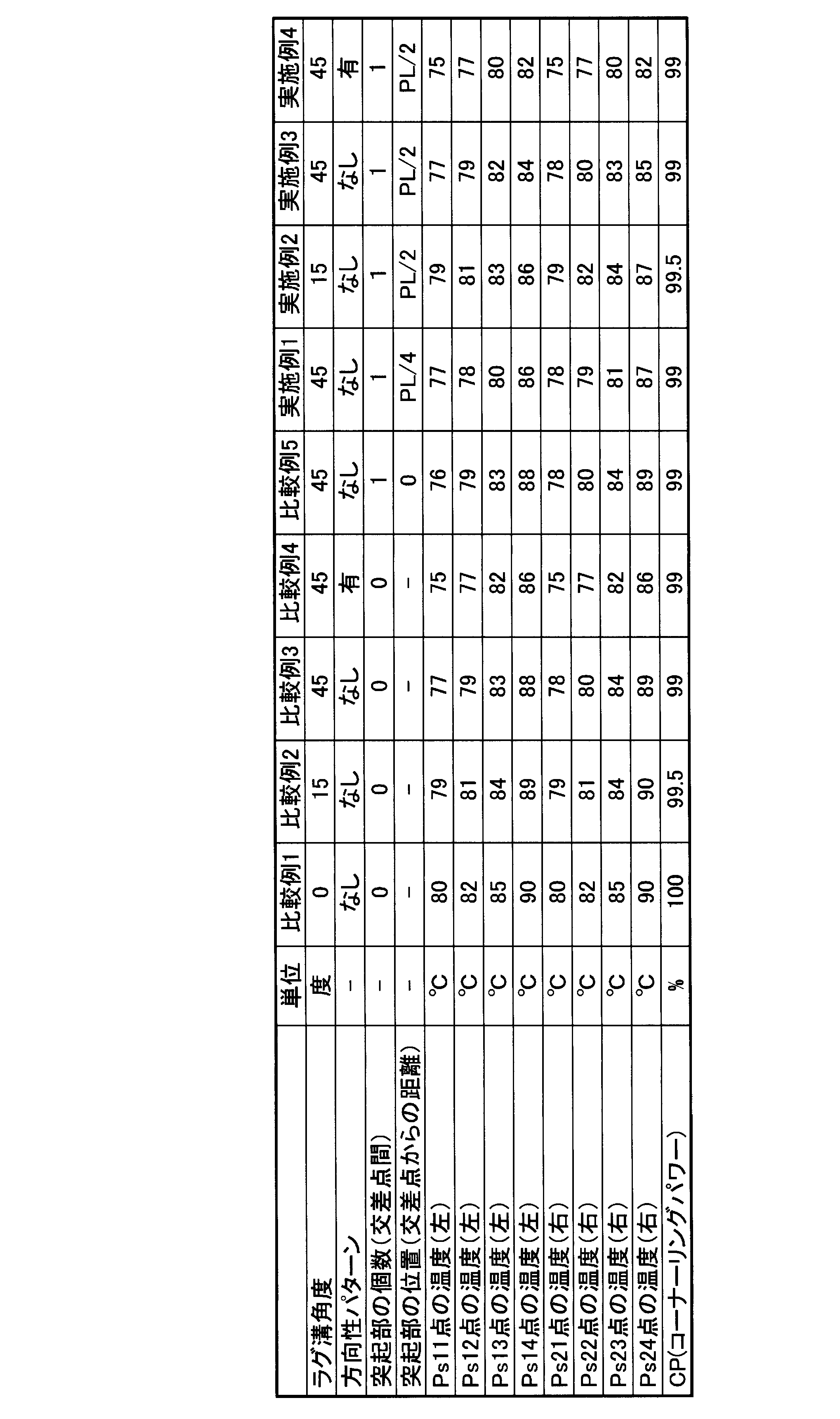
- Comparative Examples 1 to 4 tires having no protrusions in circumferential grooves were used.
- Comparative Examples 1 to 3 and Comparative Example 5 tires in which the lug grooves have no directionality with respect to the rotation direction tr1 were used.
- Comparative Example 4 a tire in which the lug groove has directionality with respect to the rotation direction tr1 was used.
- Comparative Example 1 a tire having a lug groove inclination angle ⁇ of 0 degrees was used. As Comparative Example 2, a tire having a lug groove inclination angle ⁇ of 15 degrees was used. As Comparative Example 3, a tire having a lug groove inclination angle ⁇ of 45 degrees was used. As Comparative Example 4, a tire having a lug groove inclination angle ⁇ of 45 degrees was used. As Comparative Example 5, a tire in which a protrusion was provided in the circumferential groove and the inclination angle ⁇ of the lug groove was 45 degrees was used. In Comparative Example 5, the position of the protrusion was on the intersection.
- Examples 1 to 4 tires provided with protrusions were used.
- Examples 1 to 3 tires in which the lug grooves have no directionality with respect to the rotation direction tr1 were used.
- Example 4 a tire in which the lug groove has directionality with respect to the rotation direction tr1 was used.
- Example 1 a tire having a protrusion in the circumferential groove and an inclination angle ⁇ of the lug groove of 45 degrees was used.
- the position of the protrusion was set to a position separated by PL / 4 from the first intersection to the second intersection side.
- Example 2 a tire in which a protrusion was provided in the circumferential groove and the inclination angle ⁇ of the lug groove was 15 degrees was used.
- the position of the protrusion was set to a position separated by PL / 2 from the first intersection to the second intersection side.
- Example 3 a tire having a protrusion in the circumferential groove and an inclination angle ⁇ of the lug groove of 45 degrees was used.
- the position of the protrusion was set to a position separated by PL / 2 from the first intersection to the second intersection side.
- Example 4 a tire in which a protrusion was provided in the circumferential groove and the inclination angle ⁇ of the lug groove was 45 degrees was used.
- the position of the protrusion was set to a position separated by PL / 2 from the first intersection to the second intersection side.
- the lug groove formed on one side of the tread width direction twd and the lug groove formed on the other side of the tread width direction twd have the same directionality (directionality) with respect to the rotation direction.
- a tire having a pattern) was used.
- Test method The tire was rolled by an indoor drum testing machine, and the temperature at the end in the tread width direction of the circumferential land portion 70B was measured. As shown in FIG. 10, the measurement points are the sum of Ps11 to Ps14 points on one side (left) of the tire equator line CL and Ps21 to Ps24 points on the other side (right) of the tire equator line CL. Eight points were targeted.
- the points Ps11 to Ps14 indicate the distance from the intersection of the lug groove 60 and the circumferential groove 50 on the left side shown in FIG. 10, and the points Ps21 to Ps24 are the lug grooves on the right side shown in FIG. The distance from the intersection of 60 and the circumferential groove
- channel 50 is shown.
- the points Ps11 and Ps21 indicate the same positions as the intersections in the tire circumferential direction tcd, and the points Ps12 and Ps22 are 1/4 ⁇ from the intersections in the tire circumferential direction tcd.
- Ps13 and Ps23 points are positions separated by 1/2 ⁇ PL from the intersection in the tire circumferential direction tcd, and Ps14 and Ps24 points are located from the intersection in the tire circumferential direction tcd. A position 3/4 ⁇ PL apart is shown.
- Example 5-7 the temperature rise suppressing effect equal to or higher than that of Example 2-4 was obtained. In particular, an increase in temperature at the Ps14 point and the Ps24 point is suppressed.
- the shape of the protrusion 500 is a flat plate shape, but is not limited thereto.
- the shape of the protruding portion 500 is, for example, a waveform in a tread surface view, a shape in which the vicinity of the circumferential groove extension line TCL is thick, and narrows toward the side wall 51 and the side wall 53 (or vice versa). May be.
- angle ⁇ f, the groove depth D, and the groove width W may not necessarily satisfy the conditions defined in the above-described embodiment.
- the circumferential groove 50 extends in parallel to the tire circumferential direction tcd, but is not limited thereto.
- the circumferential groove 50 does not necessarily have to be parallel to the tire circumferential direction tcd.
- the circumferential groove 50 may not be parallel to the tire circumferential direction tcd as long as the angle formed with the tire equator line CL is 45 degrees or less.
- the circumferential groove 50 is not necessarily linear, and may be, for example, a shape curved outward in the tread width direction twd or a zigzag shape.
- channel 50 is zigzag shape, it is preferable that it is a shape where the speed of the air which flows through the circumferential groove
- the lug grooves 60 are all formed at the same angle with respect to the tire circumferential direction tcd, but are not limited thereto.
- the inclination angle ⁇ of the lug groove 60 is not necessarily the same.
- the inclination angle ⁇ of the lug groove 60 may be different between the lug groove 60 located on one end side in the tread width direction twd and the lug groove 60 located on the other end side.
- the inclination angle ⁇ of the lug grooves 60 may be different.
- the tire 1 according to the present embodiment has a remarkable effect when applied to a so-called super-large tire, but can also be applied to a general-purpose tire.
- the tire according to the present invention may be a pneumatic tire or a solid tire filled with rubber.
- a gas-filled tire other than air containing a rare gas such as argon or nitrogen may be used.
- the protrusion is provided between the first intersection and the second intersection, the protrusion is provided between the first intersection and the second intersection.
- the air relaxation layer in the circumferential groove is disturbed, and heat dissipation can be promoted. That is, heat dissipation in the groove in the circumferential groove can be promoted, and heat dissipation in the tread portion can be promoted by heat dissipation in the groove in the circumferential groove. Therefore, according to the tire according to the feature of the present invention, it is possible to provide a tire that can effectively suppress an increase in the temperature of the tread portion as the vehicle travels.
Landscapes
- Engineering & Computer Science (AREA)
- Mechanical Engineering (AREA)
- Tires In General (AREA)
Abstract
Description
(1)タイヤ1の概略構成
本発明の第1実施形態に係るタイヤ1の概略構成について、図1乃至図2を参照しながら説明する。図1は、本実施形態に係るタイヤ1の斜視図である。図2は、本実施形態に係るタイヤ1のトレッドパターンの展開図である。 [First embodiment]
(1) Schematic Configuration of
本実施形態に係る突起部500の概略構成について、図3乃至図6を参照しながら説明する。 (2) Schematic Configuration of
本実施形態に係るタイヤ1で、タイヤ周方向tcdに延びる複数の周方向溝50と、トレッド端部5eからトレッド幅方向twdに延びる複数のラグ溝60が形成されている。ラグ溝60は、トレッド端部5eに開口部60aを有するとともに、周方向溝50に開口する開口部60bを有する。ラグ溝60は、トレッド幅方向twdに対して傾斜して延在し、トレッド幅方向twdに対するラグ溝60の傾斜角度は、0度以上60度以下の範囲内である。 (3) Effects In the
(1)変形例1
次に、第1実施形態に係るタイヤ1の変形例1について、第1実施形態との相違点に着目して説明する。本変形例に係るタイヤ1では、周方向溝50の溝底52において、突起部500が、複数設けられている。 [Modification]
(1)
Next,
次に、第1実施形態に係るタイヤ1の変形例2について、第1実施形態との相違点に着目して説明する。本変形例に係るタイヤ1Bでは、トレッド幅方向twdの一方側に形成されるラグ溝60と、トレッド幅方向twdの他方側に形成されるラグ溝60とは、タイヤ赤道線CLからトレッド端部5eに向かって、回転方向tr1に対して同一の方向性(方向性パターン)を有する。 (2)
Next,
本発明に係るタイヤの効果を確かめるために、以下の測定を行った。なお、本発明は、以下の実施例に限定されない。 [Comparison evaluation]
In order to confirm the effect of the tire according to the present invention, the following measurements were performed. In addition, this invention is not limited to a following example.
<試験条件>
・ タイヤサイズ: 59/80R63のタイヤ
・ リム幅: 36インチ
・ 設定内圧: 600kPa
・ 設定荷重: 82.5ton
・ 設定速度: 8km/h
・ 試験方法: 室内ドラム試験機によりタイヤを転動させて、周方向陸部70Bのトレッド幅方向端部の温度を測定した。なお、測定点は、図10に示すように、タイヤ赤道線CLの一方側(左)のPs11点乃至Ps14点と、タイヤ赤道線CLの他方側(右)のPs21点乃至Ps24点との合計8点を対象とした。ここで、Ps11点乃至Ps14点は、図10に示す左側におけるラグ溝60と周方向溝50との交差点からの距離を示しており、Ps21点乃至Ps24点は、図10に示す右側におけるラグ溝60と周方向溝50との交差点からの距離を示している。交差点間の距離をPLとした場合に、Ps11点及びPs21点は、タイヤ周方向tcdにおいて交差点と同じ位置を示しており、Ps12点及びPs22点は、タイヤ周方向tcdにおいて交差点から1/4×PL離れた位置を示しており、Ps13点及びPs23点は、タイヤ周方向tcdにおいて交差点から1/2×PL離れた位置を示しており、Ps14点及びPs24点は、タイヤ周方向tcdにおいて交差点から3/4×PL離れた位置を示している。 The test was conducted under the following conditions <Test conditions>
-Tire size: 59 / 80R63 tire-Rim width: 36 inches-Set internal pressure: 600 kPa
・ Set load: 82.5ton
・ Setting speed: 8km / h
Test method: The tire was rolled by an indoor drum testing machine, and the temperature at the end in the tread width direction of the

本発明の実施形態を通じて本発明の内容を開示したが、この開示の一部をなす論述及び図面は、本発明を限定するものであると理解すべきではない。本発明はここでは記載していない様々な実施形態を含む。 [Other embodiments]
Although the contents of the present invention have been disclosed through the embodiments of the present invention, it should not be understood that the descriptions and drawings constituting a part of this disclosure limit the present invention. The present invention includes various embodiments not described herein.
Claims (12)
- トレッド部にタイヤ周方向に延びる周方向溝と、前記トレッド部の外側の端部であるトレッド端部に開口部を有し、前記トレッド端部から前記周方向溝までトレッド幅方向に延びるラグ溝とが形成されたタイヤであって、
前記周方向溝の溝底には、突起部が設けられ、
前記突起部は、前記周方向溝を形成する一方の側壁から、前記一方の側壁と対向する他方の側壁に向けて延在し、
前記ラグ溝は、タイヤ周方向に所定間隔を設けて複数形成されており、
前記タイヤのトレッド面視において、前記周方向溝の溝内を通る周方向溝内線と、前記ラグ溝の溝内を通るラグ溝内線とが交差する点を交差点とした場合、
前記突起部は、第1の交差点と、前記第1の交差点とタイヤ周方向において隣接する第2の交差点との間に設けられている
ことを特徴とするタイヤ。 A circumferential groove extending in the tire circumferential direction in the tread portion, and a lug groove having an opening at a tread end portion which is an outer end portion of the tread portion and extending in the tread width direction from the tread end portion to the circumferential groove. A tire formed with
A protrusion is provided on the groove bottom of the circumferential groove,
The protrusion extends from one side wall forming the circumferential groove toward the other side wall facing the one side wall,
A plurality of the lug grooves are formed at predetermined intervals in the tire circumferential direction,
In the tread surface view of the tire, when the intersection of the circumferential groove extension passing through the groove of the circumferential groove and the lug groove extension passing through the groove of the lug groove is an intersection,
The tire is characterized in that the protrusion is provided between a first intersection and a second intersection adjacent to the first intersection in the tire circumferential direction. - 前記第2の交差点は、前記第1の交差点よりもタイヤ回転方向後方に位置しており、
前記突起部は、前記第1の交差点と前記第2の交差点との間隔をPLとした場合、前記第1の交差点からPL/4の点よりも前記第2の交差点側に設けられている
ことを特徴とする請求項1に記載のタイヤ。 The second intersection is located behind the first intersection in the tire rotation direction,
The protrusion is provided on the second intersection side from the first intersection to the point of PL / 4, where PL is the interval between the first intersection and the second intersection. The tire according to claim 1. - 前記突起部は、前記第1の交差点から3PL/4より、タイヤ回転方向前方に設けられている
ことを特徴とする請求項1又は2に記載のタイヤ。 The tire according to claim 1, wherein the protrusion is provided forward of the tire rotation direction from 3PL / 4 from the first intersection. - 前記トレッド部のトレッド幅方向における幅をTWとした場合、
前記周方向溝は、タイヤ赤道線からトレッド幅方向外側に向かって、TW/8の位置に形成されている
ことを特徴とする請求項1乃至3何れか一項に記載のタイヤ。 When the width in the tread width direction of the tread portion is TW,
The tire according to any one of claims 1 to 3, wherein the circumferential groove is formed at a position of TW / 8 from the tire equator line toward the outer side in the tread width direction. - 前記タイヤのトレッド面視において、前記ラグ溝は、トレッド幅方向に対して傾斜して延在し、
トレッド幅方向に対する前記ラグ溝の傾斜角度は、0度以上60度以下である
ことを特徴とする請求項1乃至4の何れか一項に記載のタイヤ。 In the tread surface view of the tire, the lug groove extends inclined with respect to the tread width direction,
The tire according to any one of claims 1 to 4, wherein an inclination angle of the lug groove with respect to a tread width direction is not less than 0 degrees and not more than 60 degrees. - 前記ラグ溝は、タイヤ赤道線を境として、トレッド幅方向の一方側とトレッド幅方向の他方側とに形成されており、
トレッド幅方向の一方側に形成される前記ラグ溝と、トレッド幅方向の他方側に形成される前記ラグ溝とは、タイヤ赤道線から前記トレッド端部に向かって、タイヤ回転方向に対して同一の方向性を有する
ことを特徴とする請求項1乃至5の何れか一項に記載のタイヤ。 The lug groove is formed on one side in the tread width direction and the other side in the tread width direction with the tire equator line as a boundary,
The lug groove formed on one side in the tread width direction and the lug groove formed on the other side in the tread width direction are the same with respect to the tire rotation direction from the tire equator line toward the tread edge. The tire according to any one of claims 1 to 5, wherein the tire has the following directionality. - 前記ラグ溝は、タイヤ赤道線を境として、トレッド幅方向の一方側とトレッド幅方向の他方側とに形成されており、
トレッド幅方向の一方側に形成されるラグ溝と、トレッド幅方向の他方側に形成されるラグ溝とは、タイヤ赤道線から前記トレッド端部に向かって、タイヤ回転方向に対して異なる方向性を有する
ことを特徴とする請求項1乃至5の何れか一項に記載のタイヤ。 The lug groove is formed on one side in the tread width direction and the other side in the tread width direction with the tire equator line as a boundary,
The lug groove formed on one side in the tread width direction and the lug groove formed on the other side in the tread width direction have different directivities with respect to the tire rotation direction from the tire equator line toward the tread edge. The tire according to any one of claims 1 to 5, characterized by comprising: - 前記突起部は、前記周方向溝の前記一方の側壁に連結する側壁連結部分を有する上面部を有しており、
トレッド幅方向に沿った断面において、前記側壁連結部分の断面形状は、曲率半径R1からなる円弧状に形成されており、
前記上面部の幅をTWfとした場合、
前記曲率半径R2は、0.1TWf≦R1≦0.4TWfの関係を満たす
ことを特徴とする請求項1乃至7の何れか一項に記載のタイヤ。 The protrusion has an upper surface portion having a side wall connecting portion connected to the one side wall of the circumferential groove,
In the cross-section along the tread width direction, the cross-sectional shape of the side wall connecting portion is formed in an arc shape having a curvature radius R1,
When the width of the upper surface portion is TWf,
The tire according to any one of claims 1 to 7, wherein the curvature radius R2 satisfies a relationship of 0.1TWf≤R1≤0.4TWf. - 前記突起部は、前記周方向溝の前記溝底に連結する溝底連結部分を有する側面部を有しており、
前記突起部の幅方向に沿った断面において、前記溝底連結部分の断面形状は、曲率半径R2からなる円弧状に形成されており、
前記突起部の前記溝底からの高さをHfとした場合、
前記曲率半径R1は、0.1Hf≦R2≦Hfの関係を満たす
ことを特徴とする請求項1乃至8の何れか一項に記載のタイヤ。 The protruding portion has a side surface portion having a groove bottom connecting portion connected to the groove bottom of the circumferential groove,
In the cross section along the width direction of the protruding portion, the cross-sectional shape of the groove bottom connecting portion is formed in an arc shape having a curvature radius R2,
When the height of the protrusion from the groove bottom is Hf,
The tire according to any one of claims 1 to 8, wherein the radius of curvature R1 satisfies a relationship of 0.1Hf≤R2≤Hf. - 前記突起部は、前記第1の交差点と前記第2の交差点との間において、複数設けられている
ことを特徴とする請求項1乃至9の何れか一項に記載のタイヤ。 The tire according to any one of claims 1 to 9, wherein a plurality of the protrusions are provided between the first intersection and the second intersection. - 前記トレッド部における前記ラグ溝の形成数は、前記タイヤ赤道線よりもトレッド幅方向の一方側において20本以上80本以下である
ことを特徴とする請求項1乃至10の何れか一項に記載のタイヤ。 The number of the lug grooves formed in the tread portion is 20 or more and 80 or less on one side in the tread width direction from the tire equator line. Tires. - 前記突起部は、タイヤ周方向に対して傾斜して設けられている
ことを特徴とする請求項1乃至11の何れか一項に記載のタイヤ。 The tire according to any one of claims 1 to 11, wherein the protrusion is provided to be inclined with respect to the tire circumferential direction.
Priority Applications (5)
| Application Number | Priority Date | Filing Date | Title |
|---|---|---|---|
| JP2013532389A JP5690407B2 (en) | 2012-07-04 | 2013-07-04 | tire |
| US14/412,518 US9815337B2 (en) | 2012-07-04 | 2013-07-04 | Pneumatic tire |
| ES13813374.9T ES2651301T3 (en) | 2012-07-04 | 2013-07-04 | Tire |
| EP13813374.9A EP2871072B1 (en) | 2012-07-04 | 2013-07-04 | Tire |
| CN201380034697.8A CN104395109B (en) | 2012-07-04 | 2013-07-04 | Tire |
Applications Claiming Priority (2)
| Application Number | Priority Date | Filing Date | Title |
|---|---|---|---|
| JP2012-150945 | 2012-07-04 | ||
| JP2012150945 | 2012-07-04 |
Publications (1)
| Publication Number | Publication Date |
|---|---|
| WO2014007321A1 true WO2014007321A1 (en) | 2014-01-09 |
Family
ID=49882072
Family Applications (1)
| Application Number | Title | Priority Date | Filing Date |
|---|---|---|---|
| PCT/JP2013/068350 WO2014007321A1 (en) | 2012-07-04 | 2013-07-04 | Tire |
Country Status (6)
| Country | Link |
|---|---|
| US (1) | US9815337B2 (en) |
| EP (1) | EP2871072B1 (en) |
| JP (3) | JP5690407B2 (en) |
| CN (1) | CN104395109B (en) |
| ES (1) | ES2651301T3 (en) |
| WO (1) | WO2014007321A1 (en) |
Cited By (1)
| Publication number | Priority date | Publication date | Assignee | Title |
|---|---|---|---|---|
| JP2021024523A (en) * | 2019-08-08 | 2021-02-22 | 横浜ゴム株式会社 | Pneumatic tire |
Families Citing this family (12)
| Publication number | Priority date | Publication date | Assignee | Title |
|---|---|---|---|---|
| JP6603470B2 (en) * | 2015-04-10 | 2019-11-06 | 株式会社ブリヂストン | tire |
| FR3044596A1 (en) * | 2015-12-07 | 2017-06-09 | Michelin & Cie | PNEUMATIC TIRE TREAD FOR HEAVY VEHICLE TYPE GENIE CIVIL |
| FI127150B (en) * | 2017-01-18 | 2017-12-15 | Nokian Renkaat Oyj | Pattern bit arrangement for a pneumatic tire or wear band |
| JP6930944B2 (en) | 2018-06-21 | 2021-09-01 | 株式会社ブリヂストン | tire |
| JP7125333B2 (en) * | 2018-11-16 | 2022-08-24 | Toyo Tire株式会社 | pneumatic tire |
| CA3122580A1 (en) * | 2018-12-20 | 2020-06-25 | Bridgestone Americas Tire Operations, Llc | Tire with emerging snow feature |
| JP7116014B2 (en) * | 2019-06-12 | 2022-08-09 | 株式会社ブリヂストン | pneumatic tire |
| USD1032452S1 (en) | 2022-11-01 | 2024-06-25 | Brian Horowitz | Wheel |
| USD1035531S1 (en) | 2022-11-01 | 2024-07-16 | Brian Horowitz | Wheel |
| USD1032492S1 (en) * | 2022-11-01 | 2024-06-25 | Brian Horowitz | Wheel |
| USD1030596S1 (en) | 2022-11-01 | 2024-06-11 | Brian Horowitz | Wheel |
| USD1028857S1 (en) * | 2022-11-01 | 2024-05-28 | Brian Horowitz | Wheel |
Citations (5)
| Publication number | Priority date | Publication date | Assignee | Title |
|---|---|---|---|---|
| JPS63297108A (en) * | 1987-05-28 | 1988-12-05 | Sumitomo Rubber Ind Ltd | Pneumatic tire for heavy load vehicle |
| JP2002187411A (en) * | 2000-12-19 | 2002-07-02 | Sumitomo Rubber Ind Ltd | Pneumatic tire |
| JP2004224268A (en) * | 2003-01-24 | 2004-08-12 | Bridgestone Corp | Pneumatic tire |
| JP2005170381A (en) * | 2003-12-11 | 2005-06-30 | Goodyear Tire & Rubber Co:The | Tire tread |
| JP2009160994A (en) | 2007-12-28 | 2009-07-23 | Bridgestone Corp | Pneumatic tire |
Family Cites Families (17)
| Publication number | Priority date | Publication date | Assignee | Title |
|---|---|---|---|---|
| LU58968A1 (en) * | 1968-06-27 | 1969-11-11 | ||
| JPH03197207A (en) | 1989-12-27 | 1991-08-28 | Bridgestone Corp | Pneumatic tire for construction vehicle |
| JP2724122B2 (en) | 1993-12-27 | 1998-03-09 | 廣壽 深田 | Vehicle tires |
| CA2156392A1 (en) | 1993-12-27 | 1995-07-06 | Hirohisa Fukata | Tire for vehicle |
| US6957676B2 (en) | 1999-11-30 | 2005-10-25 | Pirelli Pneumatici S.P.A. | Tire for a vehicle wheel including at least two circumferential series of inclined incisions delimiting at least three rows of blocks |
| JP4637319B2 (en) * | 2000-04-20 | 2011-02-23 | 株式会社ブリヂストン | Heavy duty pneumatic tire |
| JP3999521B2 (en) * | 2002-01-15 | 2007-10-31 | 株式会社ブリヂストン | Pneumatic tire |
| US7537033B2 (en) * | 2002-11-26 | 2009-05-26 | The Yokohama Rubber Co., Ltd. | Pneumatic tire with tread including circumferential grooves having inclined ridges or recesses |
| JP2005053257A (en) | 2003-08-04 | 2005-03-03 | Yokohama Rubber Co Ltd:The | Pneumatic tire |
| ES2334369T3 (en) * | 2004-06-23 | 2010-03-09 | Bridgestone Corporation | TIRE. |
| ES2396549T3 (en) * | 2004-08-03 | 2013-02-22 | Bridgestone Corporation | Tire cover |
| JP4785440B2 (en) | 2005-06-22 | 2011-10-05 | 株式会社ブリヂストン | Pneumatic tire |
| KR101108289B1 (en) * | 2007-03-12 | 2012-01-25 | 가부시키가이샤 브리지스톤 | Pneumatic tire |
| JP5258210B2 (en) * | 2007-06-05 | 2013-08-07 | 株式会社ブリヂストン | Pneumatic tire |
| KR20110125301A (en) | 2010-05-13 | 2011-11-21 | 금호타이어 주식회사 | Vehicle tire with improved heat emission performance |
| JP5578051B2 (en) | 2010-09-24 | 2014-08-27 | 横浜ゴム株式会社 | Pneumatic tire |
| JP5557875B2 (en) * | 2012-05-18 | 2014-07-23 | 株式会社ブリヂストン | Pneumatic tire |
-
2013
- 2013-07-04 CN CN201380034697.8A patent/CN104395109B/en not_active Expired - Fee Related
- 2013-07-04 EP EP13813374.9A patent/EP2871072B1/en not_active Not-in-force
- 2013-07-04 ES ES13813374.9T patent/ES2651301T3/en active Active
- 2013-07-04 WO PCT/JP2013/068350 patent/WO2014007321A1/en active Application Filing
- 2013-07-04 JP JP2013532389A patent/JP5690407B2/en not_active Expired - Fee Related
- 2013-07-04 US US14/412,518 patent/US9815337B2/en active Active
-
2014
- 2014-11-18 JP JP2014233678A patent/JP6055457B2/en not_active Expired - Fee Related
-
2016
- 2016-08-31 JP JP2016169528A patent/JP6273331B2/en not_active Expired - Fee Related
Patent Citations (5)
| Publication number | Priority date | Publication date | Assignee | Title |
|---|---|---|---|---|
| JPS63297108A (en) * | 1987-05-28 | 1988-12-05 | Sumitomo Rubber Ind Ltd | Pneumatic tire for heavy load vehicle |
| JP2002187411A (en) * | 2000-12-19 | 2002-07-02 | Sumitomo Rubber Ind Ltd | Pneumatic tire |
| JP2004224268A (en) * | 2003-01-24 | 2004-08-12 | Bridgestone Corp | Pneumatic tire |
| JP2005170381A (en) * | 2003-12-11 | 2005-06-30 | Goodyear Tire & Rubber Co:The | Tire tread |
| JP2009160994A (en) | 2007-12-28 | 2009-07-23 | Bridgestone Corp | Pneumatic tire |
Cited By (2)
| Publication number | Priority date | Publication date | Assignee | Title |
|---|---|---|---|---|
| JP2021024523A (en) * | 2019-08-08 | 2021-02-22 | 横浜ゴム株式会社 | Pneumatic tire |
| JP7385107B2 (en) | 2019-08-08 | 2023-11-22 | 横浜ゴム株式会社 | pneumatic tires |
Also Published As
| Publication number | Publication date |
|---|---|
| JP2016196299A (en) | 2016-11-24 |
| JPWO2014007321A1 (en) | 2016-06-02 |
| ES2651301T3 (en) | 2018-01-25 |
| JP5690407B2 (en) | 2015-03-25 |
| CN104395109A (en) | 2015-03-04 |
| US9815337B2 (en) | 2017-11-14 |
| EP2871072A4 (en) | 2016-01-27 |
| JP2015057344A (en) | 2015-03-26 |
| JP6055457B2 (en) | 2016-12-27 |
| JP6273331B2 (en) | 2018-01-31 |
| CN104395109B (en) | 2017-04-05 |
| EP2871072A1 (en) | 2015-05-13 |
| EP2871072B1 (en) | 2017-09-20 |
| US20150151590A1 (en) | 2015-06-04 |
Similar Documents
| Publication | Publication Date | Title |
|---|---|---|
| JP6273331B2 (en) | tire | |
| JP5636399B2 (en) | tire | |
| JP5690310B2 (en) | tire | |
| JP6006549B2 (en) | tire | |
| JP5600143B2 (en) | tire | |
| WO2014007317A1 (en) | Tire | |
| JP5608709B2 (en) | tire | |
| JP6122259B2 (en) | tire | |
| JP6122258B2 (en) | tire | |
| JP5814425B2 (en) | tire | |
| JP6118041B2 (en) | tire | |
| JP6603471B2 (en) | tire | |
| JP5986828B2 (en) | tire |
Legal Events
| Date | Code | Title | Description |
|---|---|---|---|
| ENP | Entry into the national phase |
Ref document number: 2013532389 Country of ref document: JP Kind code of ref document: A |
|
| 121 | Ep: the epo has been informed by wipo that ep was designated in this application |
Ref document number: 13813374 Country of ref document: EP Kind code of ref document: A1 |
|
| WWE | Wipo information: entry into national phase |
Ref document number: 14412518 Country of ref document: US |
|
| NENP | Non-entry into the national phase |
Ref country code: DE |
|
| REEP | Request for entry into the european phase |
Ref document number: 2013813374 Country of ref document: EP |
|
| WWE | Wipo information: entry into national phase |
Ref document number: 2013813374 Country of ref document: EP |