WO2014007058A1 - 画像復号装置、および画像符号化装置 - Google Patents
画像復号装置、および画像符号化装置 Download PDFInfo
- Publication number
- WO2014007058A1 WO2014007058A1 PCT/JP2013/066792 JP2013066792W WO2014007058A1 WO 2014007058 A1 WO2014007058 A1 WO 2014007058A1 JP 2013066792 W JP2013066792 W JP 2013066792W WO 2014007058 A1 WO2014007058 A1 WO 2014007058A1
- Authority
- WO
- WIPO (PCT)
- Prior art keywords
- unit
- motion information
- layer
- target
- prediction
- Prior art date
- Legal status (The legal status is an assumption and is not a legal conclusion. Google has not performed a legal analysis and makes no representation as to the accuracy of the status listed.)
- Ceased
Links
Images















Classifications
-
- H—ELECTRICITY
- H04—ELECTRIC COMMUNICATION TECHNIQUE
- H04N—PICTORIAL COMMUNICATION, e.g. TELEVISION
- H04N19/00—Methods or arrangements for coding, decoding, compressing or decompressing digital video signals
- H04N19/30—Methods or arrangements for coding, decoding, compressing or decompressing digital video signals using hierarchical techniques, e.g. scalability
-
- H—ELECTRICITY
- H04—ELECTRIC COMMUNICATION TECHNIQUE
- H04N—PICTORIAL COMMUNICATION, e.g. TELEVISION
- H04N19/00—Methods or arrangements for coding, decoding, compressing or decompressing digital video signals
- H04N19/10—Methods or arrangements for coding, decoding, compressing or decompressing digital video signals using adaptive coding
- H04N19/102—Methods or arrangements for coding, decoding, compressing or decompressing digital video signals using adaptive coding characterised by the element, parameter or selection affected or controlled by the adaptive coding
- H04N19/119—Adaptive subdivision aspects, e.g. subdivision of a picture into rectangular or non-rectangular coding blocks
-
- H—ELECTRICITY
- H04—ELECTRIC COMMUNICATION TECHNIQUE
- H04N—PICTORIAL COMMUNICATION, e.g. TELEVISION
- H04N19/00—Methods or arrangements for coding, decoding, compressing or decompressing digital video signals
- H04N19/50—Methods or arrangements for coding, decoding, compressing or decompressing digital video signals using predictive coding
- H04N19/503—Methods or arrangements for coding, decoding, compressing or decompressing digital video signals using predictive coding involving temporal prediction
- H04N19/51—Motion estimation or motion compensation
- H04N19/513—Processing of motion vectors
-
- H—ELECTRICITY
- H04—ELECTRIC COMMUNICATION TECHNIQUE
- H04N—PICTORIAL COMMUNICATION, e.g. TELEVISION
- H04N19/00—Methods or arrangements for coding, decoding, compressing or decompressing digital video signals
- H04N19/50—Methods or arrangements for coding, decoding, compressing or decompressing digital video signals using predictive coding
- H04N19/503—Methods or arrangements for coding, decoding, compressing or decompressing digital video signals using predictive coding involving temporal prediction
- H04N19/51—Motion estimation or motion compensation
- H04N19/55—Motion estimation with spatial constraints, e.g. at image or region borders
-
- H—ELECTRICITY
- H04—ELECTRIC COMMUNICATION TECHNIQUE
- H04N—PICTORIAL COMMUNICATION, e.g. TELEVISION
- H04N19/00—Methods or arrangements for coding, decoding, compressing or decompressing digital video signals
- H04N19/70—Methods or arrangements for coding, decoding, compressing or decompressing digital video signals characterised by syntax aspects related to video coding, e.g. related to compression standards
Definitions
- the present invention relates to an image decoding apparatus that decodes hierarchically encoded data in which an image is hierarchically encoded, and an image encoding apparatus that generates hierarchically encoded data by hierarchically encoding an image.
- One of information transmitted in a communication system or information recorded in a storage device is an image or a moving image. 2. Description of the Related Art Conventionally, a technique for encoding an image for transmitting and storing these images (hereinafter including moving images) is known.
- Non-Patent Document 1 As the video encoding system, H.264 H.264 / MPEG-4. AVC and HEVC (High-Efficiency Video Coding) which is a successor codec are known (Non-Patent Document 1).
- a predicted image is usually generated based on a local decoded image obtained by encoding / decoding an input image, and obtained by subtracting the predicted image from the input image (original image).
- Prediction residuals (sometimes referred to as “difference images” or “residual images”) are encoded.
- examples of the method for generating a predicted image include inter-screen prediction (inter prediction) and intra-screen prediction (intra prediction).
- predicted images in a corresponding frame are sequentially generated based on a locally decoded image in the same frame.
- a predicted image is generated by motion compensation between frames.
- Information relating to motion compensation (motion compensation parameters) is often not directly encoded to reduce the amount of code. Therefore, in the inter prediction, a motion compensation parameter is estimated based on a decoding situation or the like around the target block.
- a list of motion compensation parameter candidates (merge candidates) is generated, and motion compensation of the predicted image is performed using merge candidates selected from the list by an index.
- the merge candidate list includes spatial candidates derived based on the motion information of adjacent regions. In the derivation of the space candidate, the adjacent region is selected from regions located at the upper left, upper right, and lower right of the prediction unit to be decoded.
- a list of motion compensation parameter candidates (predicted motion vector candidates) is generated, and motion compensation parameters are derived from the motion compensation candidates selected by index from the list and the difference motion vector. Perform motion compensation.
- Hierarchical coding methods include ISO / IEC and ITU-T standards as H.264. H.264 / AVC Annex G Scalable Video Coding (SVC).
- SVC supports spatial scalability, temporal scalability, and SNR scalability.
- spatial scalability an image obtained by down-sampling an original image to a desired resolution is used as a lower layer. It is encoded with H.264 / AVC.
- the upper layer performs inter-layer prediction in order to remove redundancy between layers.
- inter-layer prediction there is motion information prediction in which information related to motion prediction is predicted from information in a lower layer at the same time, or texture prediction in which prediction is performed from an image obtained by up-sampling a decoded image in a lower layer at the same time (non-patent document 2).
- motion information prediction motion information is encoded using motion information of a reference layer as an estimated value.
- HEVC High efficiency video coding
- JCT-VC Joint Collaborative Team on Video Coding
- the motion information included in the candidate list has a lot of motion information corresponding to the upper left area, and there is little motion information corresponding to the lower right area. This is because, in the same layer, motion information corresponding to the lower right region has not been derived and cannot be used as a merge candidate. For this reason, the estimation accuracy of motion information is not sufficient, and a desired code amount reduction effect may not be obtained.
- the present invention has been made in view of the above problems, and an object of the present invention is to reduce the amount of code of motion information by deriving various motion information as candidates in the generation of a motion information candidate list in hierarchical coding.
- An image decoding device and an image encoding device that can be used are realized.
- an image decoding apparatus decodes hierarchically encoded data in which image information relating to images of different quality for each layer is hierarchically encoded, and is a target to be decoded.
- An image decoding device that restores motion information in a layer and restores an image in the target layer using a predicted image generated by motion compensated prediction based on the restored motion information, and a process for generating a predicted image in the target layer
- the target prediction unit as a target, reference is made to a reference layer that is a decoded layer, and motion information decoded in a region on the reference layer corresponding to a region that has not been decoded in a peripheral region including the target prediction unit, It further comprises an interlayer candidate deriving unit that derives a candidate for estimating motion information in the target prediction unit.
- the image decoding device is a so-called hierarchical image decoding device that decodes hierarchically encoded data in which image information relating to images of different quality for each layer is hierarchically encoded, and restores the image.
- Such a hierarchical coding method is sometimes referred to as (SVC; Scalable Video Coding), and is standardized in, for example, H.264 / AVC Annex G GSVC.
- the quality of a moving image here means a factor that affects the appearance of a subjective and objective moving image.
- the quality of the moving image includes, for example, “resolution”, “frame rate”, and “image quality”.
- a layer corresponding to higher quality is referred to as a higher layer
- a layer corresponding to lower quality is referred to as a lower layer.
- the target layer refers to a layer that is a decoding target.
- the motion information in the target layer is restored, and the image in the target layer is restored using a prediction image generated by motion compensation prediction based on the restored motion information.
- the prediction method by motion compensation prediction based on motion information may be called an inter prediction method.
- the reference layer that is the decoded layer is referred to in the target prediction unit that is the processing target of the predicted image generation in the target layer.
- a layer in which image information has been decoded may be referred to when a target layer is decoded.
- a layer referred to when decoding a target layer is referred to as a reference layer.
- the reference layer is generally a lower layer of the target layer. However, it is not necessary to refer to all layers lower than the target layer, and at least a lower layer in which information necessary for decoding in the target layer is decoded may be referred to.
- the motion information decoded in the region on the reference layer corresponding to the undecoded region in the peripheral region including the target prediction unit is used as a candidate for estimating the motion information in the target prediction unit.
- the peripheral area including the target prediction unit is an area within a predetermined range from the target prediction unit and including the target prediction unit.
- the peripheral area including the target prediction unit includes, for example, an adjacent peripheral area of the target prediction unit.
- the undecoded area means an area where motion information is not decoded.
- the candidate for estimating the motion information is information for estimating a motion compensation parameter based on the decoding situation around the target prediction unit. For example, it corresponds to a merge candidate in HEVC. One or a plurality of such candidates are listed. This list may be referred to as a merge candidate list.
- motion information on a reference area corresponding to an area that cannot be used because it has not been decoded in the same layer can be added to the merge candidate list.
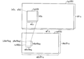
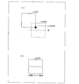
- a region on the reference layer corresponding to an undecoded region in a peripheral region including the target prediction unit is a lower right pixel in a region on the reference layer corresponding to the target prediction unit. It is preferable that it is a lower right area
- motion information in a predetermined range area surrounding the lower right pixel of the target prediction unit that cannot be used because it is not decoded in the same layer can be added as a motion information candidate. Since the motion information derived in the vicinity of the lower right pixel in the region on the reference layer is likely to be different in nature from the motion information in the upper left region of the target layer, a higher code amount reduction effect can be expected.
- the lower right area is a motion information recording unit including a lower right pixel in an area on a reference layer corresponding to the target prediction unit.
- motion information corresponding to the lower right pixel of the target prediction unit that cannot be used because it is not decoded in the same layer can be added as a motion information candidate. Since the motion information corresponding to the lower right pixel is likely to be different in nature from the motion information in the upper left region, a higher code amount reduction effect can be expected.
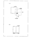
- the lower right region is one of right, lower, and lower right of a motion information recording unit including a lower right pixel in a region on a reference layer corresponding to the target prediction unit. It is preferable that the motion information recording unit be adjacent to.
- the pixel corresponding to the upper left position and the pixel corresponding to the lower right position in the region on the reference layer are the same motion information recording unit May belong to.
- the motion of the motion information recording unit adjacent to any one of the right, the lower, and the lower right of the motion information recording unit including the lower right pixel in the region on the reference layer corresponding to the target prediction unit Information can be used. For this reason, the possibility that motion information can be derived from a recording unit different from the upper left portion in the corresponding reference area is increased. This increases the possibility that various motion information can be derived.
- the interlayer candidate deriving unit derives a plurality of pieces of motion information including motion information in the lower right region as the candidates, and the motion information in the lower right region It is preferable to derive with priority over motion information.
- the interlayer candidate deriving unit includes, as the other motion information, motion information in a motion information recording unit including at least an upper left pixel in a region on a reference layer corresponding to the target prediction unit. Is preferably derived.
- the image decoding apparatus further includes a determination unit that determines whether or not the motion information derived as a candidate matches the motion information that has been derived as a candidate.
- a determination unit determines whether or not the motion information derived as a candidate matches the motion information that has been derived as a candidate.
- the image decoding apparatus further includes target layer candidate derivation means for deriving motion information candidates based on the decoded information decoded in the target layer, and the match determination means includes the interlayer candidate derivation means as candidates. It is preferable not to perform a match determination between the motion information derived as the motion information derived as candidates by the target layer candidate deriving unit.
- motion information candidate deriving processing by the interlayer candidate deriving unit When the motion information derived as a candidate by the interlayer candidate deriving unit and the motion information derived as a candidate by the target layer candidate deriving unit are determined to match, motion information candidate deriving processing by the interlayer candidate deriving unit, Parallel execution performance with the motion information candidate derivation process by the target layer candidate derivation means is reduced. For example, when performing the above-described matching determination, the motion information candidate derivation process by the target layer candidate derivation unit is executed in series after the motion information candidate derivation process by the interlayer candidate derivation unit is completed. become.
- the motion information derived as candidates by the target layer candidate deriving unit is determined to match, but the above-described match determination is not performed.
- the parallel executability of the motion information candidate deriving process by the interlayer candidate deriving means and the motion information candidate deriving process by the target layer candidate deriving means can be improved.
- spatial motion information candidate deriving means for deriving motion information candidates based on motion information decoded in the peripheral region of the target prediction unit, and motion information derived as candidates are: Determining means for determining whether or not the motion information already derived as a candidate matches, and the interlayer candidate derivation means derives motion information to be derived as a candidate by the spatial motion information candidate derivation means. It is preferable to derive the motion information as a candidate when the determination unit determines that the motion information candidate does not coincide with the motion information candidate having the highest priority.
- the motion information to be derived as a candidate by the interlayer candidate deriving unit matches the motion information candidate having the highest priority among the motion information candidates derived by the spatial motion information candidate deriving unit.
- the interlayer candidate deriving means derives the motion information as a candidate.
- the image decoding apparatus further comprises temporal motion information candidate deriving means for deriving motion information candidates based on motion information decoded in a picture different from the picture to which the target prediction unit belongs,
- the information candidate deriving means preferably does not execute the motion information candidate deriving process when the motion information candidate deriving process is executed by the interlayer candidate deriving means.
- the image decoding apparatus further comprises temporal motion information candidate derivation means for deriving motion information candidates based on motion information decoded in a picture different from the picture to which the target prediction unit belongs, Preferably, the derivation unit does not execute the motion information candidate derivation process when the motion information candidate derivation process is performed by the temporal motion information candidate derivation unit.
- the code amount reduction width of motion information when both the interlayer candidate deriving unit and the temporal motion information candidate deriving unit derive motion information candidates the code amount of motion information when either one derives motion information candidates There is no big difference with the reduction range.
- the temporal motion information candidate deriving unit when the motion information candidate is derived by the interlayer candidate deriving unit, the temporal motion information candidate deriving unit does not derive the motion information candidate.
- the amount of processing required for the temporal motion information candidate derivation means to derive the motion information candidates and the amount of memory for recording the motion vector of the reference image are reduced while suppressing a large increase in the amount of motion information codes. can do. The reverse is also true.
- an image encoding device encodes image information related to images of different quality for each layer and generates encoded hierarchical data when generating hierarchical encoded data.
- An image encoding device that subtracts a prediction image generated by motion compensated prediction based on motion information derived in a target layer to generate a prediction residual in the target layer by subtracting from an input original image in the target layer,
- a target prediction unit that is a processing target of predicted image generation in the target layer
- a reference layer that is a decoded layer is referred to, and a region on the reference layer that corresponds to a region that has not been decoded in a peripheral region that includes the target prediction unit
- Interlayer candidate deriving means for deriving the decoded motion information as a candidate for estimating the motion information in the target prediction unit. Characterized in that it obtain.
- the image coding apparatus configured as described above is also within the scope of the present invention, and in this case as well, the same operations and effects as those of the image decoding apparatus can be obtained.
- the data structure of hierarchically encoded data generated by the image encoding device and decoded by the image decoding device is also within the scope of the present invention.
- the image decoding apparatus decodes hierarchically encoded data in which image information relating to images of different quality for each layer is hierarchically decoded, and restores motion information in a target layer to be decoded,
- An image decoding apparatus that restores an image in the target layer using a prediction image generated by motion compensation prediction based on the restored motion information, and in a target prediction unit that is a processing target of prediction image generation in the target layer, Reference is made to a reference layer that is a decoded layer, motion information decoded in a region on the reference layer corresponding to an undecoded region in the peripheral region including the target prediction unit, and motion information in the target prediction unit It is a structure provided with the interlayer candidate derivation
- the image encoding device when generating hierarchically encoded data by hierarchically encoding image information relating to images of different quality for each layer, motion information derived in a target layer to be encoded
- An image encoding device that generates a prediction residual in the target layer by subtracting a prediction image generated by motion compensated prediction based on the input original image in the target layer, and a process for generating a predicted image in the target layer
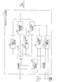
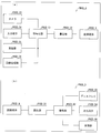
- FIG. 1 It is a functional block diagram which illustrates about the structure of the merge candidate derivation
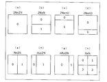
- FIG. 7 is a diagram illustrating PU partition type patterns, where (a) to (h) are PU partition types 2N ⁇ N, 2N ⁇ nU, 2N ⁇ nD, 2N ⁇ N, 2N ⁇ nU, and 2N, respectively. The partition shape in the case of xnD is shown. It is a functional block diagram which shows the schematic structure of the said hierarchy moving image decoding apparatus.
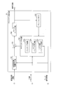
- leading-out part is provided.
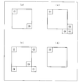
- (A) to (c) show examples in which inter-layer merge candidates are derived from two or more positions.
- (D) shows an example of prohibiting the derivation of inter-layer merge candidates.
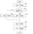
- It is a flowchart which shows another example of the flow of operation
- It is a functional block diagram illustrated about the structure which concerns on the modification of the said merge candidate derivation
- FIG. 1 It is the figure shown about the structure of the recording device carrying the said hierarchy moving image encoder, and the reproducing
- (A) shows a recording device equipped with a hierarchical video encoding device, and (b) shows a playback device equipped with a hierarchical video decoding device.
- a hierarchical moving picture decoding apparatus 1 and the hierarchical moving picture encoding apparatus 2 will be described as follows based on FIGS. ⁇ Overview ⁇
- a hierarchical video decoding device (image decoding device) 1 receives encoded data that has been subjected to scalable video coding (SVC) by a hierarchical video encoding device (image encoding device) 2.
- Scalable video coding is a coding method that hierarchically encodes moving images from low quality to high quality. Scalable video coding is, for example, H.264. H.264 / AVC Annex G SVC. Note that the quality of a moving image here widely means an element that affects the appearance of a subjective and objective moving image.
- the quality of the moving image includes, for example, “resolution”, “frame rate”, “image quality”, and “pixel representation accuracy”. Therefore, hereinafter, if the quality of the moving image is different, it means that, for example, “resolution” is different, but it is not limited thereto. For example, in the case of moving images quantized in different quantization steps (that is, moving images encoded with different encoding noises), it can be said that the quality of moving images is different from each other.
- SVC is also classified into (1) spatial scalability, (2) temporal scalability, and (3) SNR (Signal-to-Noise-Ratio) scalability from the viewpoint of the type of information layered.
- Spatial scalability is a technique for hierarchizing resolution and image size.
- Time scalability is a technique for layering at a frame rate (the number of frames per unit time).
- SNR scalability is a technique for hierarchizing in coding noise.
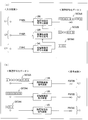
- FIG. 2 is a diagram schematically illustrating a case where a moving image is hierarchically encoded / decoded by three layers of a lower layer L3, a middle layer L2, and an upper layer L1. That is, in the example shown in FIGS. 2A and 2B, of the three layers, the upper layer L1 is the highest layer and the lower layer L3 is the lowest layer.
- a decoded image corresponding to a specific quality that can be decoded from hierarchically encoded data is referred to as a decoded image of a specific hierarchy (or a decoded image corresponding to a specific hierarchy) (for example, in the upper hierarchy L1).
- Decoded image POUT # A a decoded image of a specific hierarchy (or a decoded image corresponding to a specific hierarchy) (for example, in the upper hierarchy L1).
- FIG. 2A shows a hierarchical moving image encoding apparatus 2 # A to 2 # C that generates encoded data DATA # A to DATA # C by hierarchically encoding input images PIN # A to PIN # C, respectively. Is shown.
- FIG. 2B shows a hierarchical moving picture decoding apparatus 1 # A ⁇ that generates decoded images POUT # A ⁇ POUT # C by decoding the encoded data DATA # A ⁇ DATA # C, which are encoded hierarchically. 1 # C is shown.
- the input images PIN # A, PIN # B, and PIN # C that are input on the encoding device side have the same original image but different image quality (resolution, frame rate, image quality, and the like).
- the image quality decreases in the order of the input images PIN # A, PIN # B, and PIN # C.
- the hierarchical video encoding device 2 # C of the lower hierarchy L3 encodes the input image PIN # C of the lower hierarchy L3 to generate encoded data DATA # C of the lower hierarchy L3.
- Basic information necessary for decoding the decoded image POUT # C of the lower layer L3 is included (indicated by “C” in FIG. 2). Since the lower layer L3 is the lowest layer, the encoded data DATA # C of the lower layer L3 is also referred to as basic encoded data.
- the hierarchical video encoding apparatus 2 # B of the middle hierarchy L2 encodes the input image PIN # B of the middle hierarchy L2 with reference to the encoded data DATA # C of the lower hierarchy, and performs the middle hierarchy L2 Encoded data DATA # B is generated.
- additional data necessary for decoding the decoded image POUT # B of the intermediate hierarchy is added to the encoded data DATA # B of the intermediate hierarchy L2.
- Information (indicated by “B” in FIG. 2) is included.
- the hierarchical video encoding apparatus 2 # A of the upper hierarchy L1 encodes the input image PIN # A of the upper hierarchy L1 with reference to the encoded data DATA # B of the intermediate hierarchy L2 to Encoded data DATA # A is generated.
- the encoded data DATA # A of the upper layer L1 is used to decode the basic information “C” necessary for decoding the decoded image POUT # C of the lower layer L3 and the decoded image POUT # B of the middle layer L2.
- additional information indicated by “A” in FIG. 2 necessary for decoding the decoded image POUT # A of the upper layer is included.
- the encoded data DATA # A of the upper layer L1 includes information related to decoded images of a plurality of different qualities.
- the decoding device side will be described with reference to FIG.
- the decoding devices 1 # A, 1 # B, and 1 # C corresponding to the layers of the upper layer L1, the middle layer L2, and the lower layer L3 are encoded data DATA # A and DATA # B, respectively.
- And DATA # C are decoded to output decoded images POUT # A, POUT # B, and POUT # C.
- the hierarchical moving picture decoding apparatus 1 # B in the middle hierarchy L2 receives information necessary for decoding the decoded picture POUT # B from the hierarchical encoded data DATA # A in the upper hierarchy L1 (that is, the hierarchical encoded data).
- the decoded image POUT # B may be decoded by extracting “B” and “C”) included in DATA # A.
- the decoded images POUT # A, POUT # B, and POUT # C can be decoded based on information included in the hierarchically encoded data DATA # A of the upper hierarchy L1.
- the hierarchical encoded data is not limited to the above three-layer hierarchical encoded data, and the hierarchical encoded data may be hierarchically encoded with two layers or may be hierarchically encoded with a number of layers larger than three. Good.
- Hierarchically encoded data may be configured as described above. For example, in the example described above with reference to FIGS. 2A and 2B, it has been described that “C” and “B” are referred to for decoding the decoded image POUT # B, but the present invention is not limited thereto. It is also possible to configure the hierarchically encoded data so that the decoded image POUT # B can be decoded using only “B”.
- Hierarchically encoded data can also be generated so that In that case, the lower layer hierarchical video encoding device generates hierarchical encoded data by quantizing the prediction residual using a larger quantization width than the upper layer hierarchical video encoding device. To do.
- Upper layer A layer located above a certain layer is referred to as an upper layer.
- the upper layers of the lower layer L3 are the middle layer L2 and the upper layer L1.
- the decoded image of the upper layer means a decoded image with higher quality (for example, high resolution, high frame rate, high image quality, etc.).
- Lower layer A layer located below a certain layer is referred to as a lower layer.
- the lower layers of the upper layer L1 are the middle layer L2 and the lower layer L3.
- the decoded image of the lower layer refers to a decoded image with lower quality.
- Target layer A layer that is the target of decoding or encoding.
- Reference layer A specific lower layer referred to for decoding a decoded image corresponding to the target layer is referred to as a reference layer.
- the reference layers of the upper hierarchy L1 are the middle hierarchy L2 and the lower hierarchy L3.
- the hierarchically encoded data can be configured so that it is not necessary to refer to all of the lower layers in decoding of the specific layer.
- the hierarchical encoded data can be configured such that the reference layer of the upper hierarchy L1 is either the middle hierarchy L2 or the lower hierarchy L3.
- Base layer A layer located at the lowest layer is referred to as a base layer.
- the decoded image of the base layer is the lowest quality decoded image that can be decoded from the encoded data, and is referred to as a basic decoded image.
- the basic decoded image is a decoded image corresponding to the lowest layer.
- the partially encoded data of the hierarchically encoded data necessary for decoding the basic decoded image is referred to as basic encoded data.
- the basic information “C” included in the hierarchically encoded data DATA # A of the upper hierarchy L1 is the basic encoded data.
- Extension layer The upper layer of the base layer is called the extension layer.
- the layer identifier is for identifying the hierarchy, and corresponds to the hierarchy one-to-one.
- the hierarchically encoded data includes a hierarchical identifier used for selecting partial encoded data necessary for decoding a decoded image of a specific hierarchy.
- a subset of hierarchically encoded data associated with a layer identifier corresponding to a specific layer is also referred to as a layer representation.
- a layer representation of the layer and / or a layer representation corresponding to a lower layer of the layer is used. That is, in decoding the decoded image of the target layer, layer representation of the target layer and / or layer representation of one or more layers included in a lower layer of the target layer are used.
- Inter-layer prediction is based on the syntax element value, the value derived from the syntax element value included in the layer expression of the layer (reference layer) different from the layer expression of the target layer, and the decoded image. It is to predict the syntax element value of the target layer, the encoding parameter used for decoding of the target layer, and the like. Inter-layer prediction in which information related to motion prediction is predicted from reference layer information (at the same time) may be referred to as motion information prediction. Further, inter-layer prediction that predicts a decoded image of a lower layer (at the same time) from an up-sampled image may be referred to as texture prediction (or inter-layer intra prediction). Note that the hierarchy used for inter-layer prediction is, for example, a lower layer of the target layer. In addition, performing prediction within a target layer without using a reference layer may be referred to as intra-layer prediction.
- the lower layer and the upper layer may be encoded by different encoding methods.
- the encoded data of each layer may be supplied to the hierarchical video decoding device 1 via different transmission paths, or supplied to the hierarchical video decoding device 1 via the same transmission path. It may be done.
- the base layer when transmitting ultra-high-definition video (moving image, 4K video data) with a base layer and one extended layer in a scalable encoding, the base layer downscales 4K video data, and interlaced video data.
- MPEG-2 or H.264 The enhancement layer may be encoded by H.264 / AVC and transmitted over a television broadcast network, and the enhancement layer may encode 4K video (progressive) with HEVC and transmit over the Internet.
- FIG. 3 is a diagram illustrating a data structure of encoded data (hierarchically encoded data DATA # C in the example of FIG. 2) that can be employed in the base layer.
- Hierarchically encoded data DATA # C illustratively includes a sequence and a plurality of pictures constituting the sequence.
- FIG. 3 shows a hierarchical structure of data in the hierarchical encoded data DATA # C.
- 3A to 3E show a sequence layer that defines a sequence SEQ, a picture layer that defines a picture PICT, a slice layer that defines a slice S, and a tree block that defines a tree block TBLK. It is a figure which shows the CU layer which prescribes
- coding unit Coding
- sequence layer a set of data referred to by the hierarchical video decoding device 1 for decoding a sequence SEQ to be processed (hereinafter also referred to as a target sequence) is defined.
- the sequence SEQ includes a sequence parameter set SPS (Sequence Parameter Set), a picture parameter set PPS (Picture Parameter Set), an adaptive parameter set APS (Adaptation Parameter Set), and pictures PICT 1 to PICT. It includes NP (NP is the total number of pictures included in the sequence SEQ) and supplemental enhancement information (SEI).
- the sequence parameter set SPS defines a set of encoding parameters that the hierarchical video decoding device 1 refers to in order to decode the target sequence.
- a set of encoding parameters referred to by the hierarchical video decoding device 1 for decoding each picture in the target sequence is defined.
- a plurality of PPS may exist. In that case, one of a plurality of PPSs is selected from each picture in the target sequence.
- the adaptive parameter set APS defines a set of encoding parameters that the hierarchical video decoding device 1 refers to in order to decode each slice in the target sequence. There may be a plurality of APSs. In that case, one of a plurality of APSs is selected from each slice in the target sequence.
- Picture layer In the picture layer, a set of data that is referred to by the hierarchical video decoding device 1 in order to decode a picture PICT to be processed (hereinafter also referred to as a target picture) is defined. As shown in FIG. 3B, the picture PICT includes a picture header PH and slices S 1 to S NS (NS is the total number of slices included in the picture PICT).
- the picture header PH includes a coding parameter group referred to by the hierarchical video decoding device 1 in order to determine a decoding method of the target picture.
- the encoding parameter group is not necessarily included directly in the picture header PH, and may be included indirectly, for example, by including a reference to the picture parameter set PPS.
- slice layer In the slice layer, a set of data that is referred to by the hierarchical video decoding device 1 in order to decode a slice S (also referred to as a target slice) to be processed is defined. As shown in FIG. 3C, the slice S includes a slice header SH and a sequence of tree blocks TBLK 1 to TBLK NC (NC is the total number of tree blocks included in the slice S).
- the slice header SH includes a coding parameter group that the hierarchical video decoding device 1 refers to in order to determine a decoding method of the target slice.
- Slice type designation information (slice_type) for designating a slice type is an example of an encoding parameter included in the slice header SH.
- I slice that uses only intra prediction at the time of encoding (2) P slice that uses unidirectional prediction or intra prediction at the time of encoding, (3) B-slice using unidirectional prediction, bidirectional prediction, or intra prediction at the time of encoding may be used.
- the slice header SH may include a reference to the picture parameter set PPS (pic_parameter_set_id) and a reference to the adaptive parameter set APS (aps_id) included in the sequence layer.
- the slice header SH includes a filter parameter FP that is referred to by an adaptive filter provided in the hierarchical video decoding device 1.
- the filter parameter FP includes a filter coefficient group.
- the filter coefficient group includes (1) tap number designation information for designating the number of taps of the filter, (2) filter coefficients a 0 to a NT-1 (NT is the total number of filter coefficients included in the filter coefficient group), and , (3) offset is included.
- Tree block layer In the tree block layer, a set of data referred to by the hierarchical video decoding device 1 for decoding a processing target tree block TBLK (hereinafter also referred to as a target tree block) is defined. Note that the tree block may be referred to as a coding tree block (CTB) or a maximum coding unit (LCU).
- CTB coding tree block
- LCU maximum coding unit
- the tree block TBLK includes a tree block header TBLKH and coding unit information CU 1 to CU NL (NL is the total number of coding unit information included in the tree block TBLK).
- NL is the total number of coding unit information included in the tree block TBLK.
- the tree block TBLK is divided into partitions for specifying a block size for each process of intra prediction or inter prediction and conversion.
- the above partition of the tree block TBLK is divided by recursive quadtree partitioning.
- the tree structure obtained by this recursive quadtree partitioning is hereinafter referred to as a coding tree.
- a partition corresponding to a leaf that is a node at the end of the coding tree is referred to as a coding node.
- the encoding node is also referred to as an encoding unit (CU).
- the coding node may be called a coding block (CB: Coding Block).
- coding unit information (hereinafter referred to as CU information)
- CU 1 to CU NL is information corresponding to each coding node (coding unit) obtained by recursively dividing the tree block TBLK into quadtrees. is there.
- the root of the coding tree is associated with the tree block TBLK.
- the tree block TBLK is associated with the highest node of the tree structure of the quadtree partition that recursively includes a plurality of encoding nodes.
- each encoding node is half the size of the encoding node to which the encoding node directly belongs (that is, the partition of the node one layer higher than the encoding node).
- the size of the tree block TBLK and the size that each coding node can take are the size specification information of the minimum coding node and the maximum coding node included in the sequence parameter set SPS of the hierarchical coding data DATA # C.
- the minimum coding node hierarchy depth difference For example, when the size of the minimum coding node is 8 ⁇ 8 pixels and the difference in the layer depth between the maximum coding node and the minimum coding node is 3, the size of the tree block TBLK is 64 ⁇ 64 pixels.
- the size of the encoding node can take any of four sizes, namely, 64 ⁇ 64 pixels, 32 ⁇ 32 pixels, 16 ⁇ 16 pixels, and 8 ⁇ 8 pixels.
- the tree block header TBLKH includes an encoding parameter referred to by the hierarchical video decoding device 1 in order to determine a decoding method of the target tree block. Specifically, as shown in FIG. 3D, tree block division information SP_TBLK that specifies a division pattern of the target tree block into each CU, and a quantization parameter difference that specifies the size of the quantization step ⁇ qp (qp_delta) is included.
- the tree block division information SP_TBLK is information representing a coding tree for dividing the tree block. Specifically, the shape and size of each CU included in the target tree block, and the position in the target tree block Is information to specify.
- the tree block division information SP_TBLK may not explicitly include the shape or size of the CU.
- the tree block division information SP_TBLK may be a set of flags indicating whether the entire target tree block or a partial region of the tree block is to be divided into four. In that case, the shape and size of each CU can be specified by using the shape and size of the tree block together.
- the quantization parameter difference ⁇ qp is a difference qp ⁇ qp ′ between the quantization parameter qp in the target tree block and the quantization parameter qp ′ in the tree block encoded immediately before the target tree block.
- CU layer In the CU layer, a set of data referred to by the hierarchical video decoding device 1 for decoding a CU to be processed (hereinafter also referred to as a target CU) is defined.
- the encoding node is a node at the root of a prediction tree (PT) and a transformation tree (TT).
- PT prediction tree
- TT transformation tree
- the encoding node is divided into one or a plurality of prediction blocks, and the position and size of each prediction block are defined.
- the prediction block is one or a plurality of non-overlapping areas constituting the encoding node.
- the prediction tree includes one or a plurality of prediction blocks obtained by the above division.
- Prediction processing is performed for each prediction block.
- a prediction block that is a unit of prediction is also referred to as a prediction unit (PU).
- PU partitioning There are roughly two types of partitioning in the prediction tree (hereinafter abbreviated as PU partitioning): intra prediction and inter prediction.
- the division method is 2N ⁇ 2N (the same size as the encoding node), 2N ⁇ N, 2N ⁇ nU, 2N ⁇ nD, N ⁇ 2N, nL ⁇ 2N, nR ⁇ 2N, and N XN etc.
- the types of PU division will be described later with reference to the drawings.
- the encoding node is divided into one or a plurality of transform blocks, and the position and size of each transform block are defined.
- the transform block is one or a plurality of non-overlapping areas constituting the encoding node.
- the conversion tree includes one or a plurality of conversion blocks obtained by the above division.
- the division in the transformation tree includes the one in which an area having the same size as the encoding node is assigned as the transformation block, and the one in the recursive quadtree division as in the above-described division of the tree block.
- transform processing is performed for each conversion block.
- the transform block which is a unit of transform is also referred to as a transform unit (TU).
- the CU information CU specifically includes a skip flag SKIP, prediction tree information (hereinafter abbreviated as PT information) PTI, and conversion tree information (hereinafter abbreviated as TT information). Include TTI).
- PT information prediction tree information
- TT information conversion tree information
- the skip flag SKIP is a flag indicating whether or not the skip mode is applied to the target PU.
- the value of the skip flag SKIP is 1, that is, when the skip mode is applied to the target CU, A part of the PT information PTI and the TT information TTI in the CU information CU are omitted. Note that the skip flag SKIP is omitted for the I slice.
- the PT information PTI is information related to a prediction tree (hereinafter abbreviated as PT) included in the CU.
- PT prediction tree
- the PT information PTI is a set of information related to each of one or a plurality of PUs included in the PT, and is referred to when a predicted image is generated by the hierarchical video decoding device 1.
- the PT information PTI includes prediction type information PType and prediction information PInfo.
- Prediction type information PType is information that specifies whether intra prediction or inter prediction is used as a prediction image generation method for the target PU.
- the prediction information PInfo includes intra prediction information PP_Intra or inter prediction information PP_Inter depending on which prediction method the prediction type information PType specifies.
- a PU to which intra prediction is applied is also referred to as an intra PU
- a PU to which inter prediction is applied is also referred to as an inter PU.
- Inter prediction information PP_Inter includes an encoding parameter that is referred to when the hierarchical video decoding device 1 generates an inter prediction image by inter prediction. More specifically, the inter prediction information PP_Inter includes inter PU division information that specifies a division pattern of the target CU into each inter PU, and inter prediction parameters for each inter PU.
- the intra prediction information PP_Intra includes an encoding parameter that is referred to when the hierarchical video decoding device 1 generates an intra predicted image by intra prediction. More specifically, the intra prediction information PP_Intra includes intra PU division information that specifies a division pattern of the target CU into each intra PU, and intra prediction parameters for each intra PU.
- the intra prediction parameter is a parameter for designating an intra prediction method (prediction mode) for each intra PU.
- the PU partition information may include information specifying the shape, size, and position of the target PU. Details of the PU partition information will be described later.
- the TT information TTI is information regarding a conversion tree (hereinafter abbreviated as TT) included in the CU.
- TT conversion tree
- the TT information TTI is a set of information regarding each of one or a plurality of TUs included in the TT, and is referred to when the hierarchical video decoding device 1 decodes residual data.
- a TU may be referred to as a block.
- the TT information TTI includes TT division information SP_TT that designates a division pattern for each transform block of the target CU, and quantized prediction residuals QD 1 to QD NT (NT is the target The total number of blocks included in the CU).
- TT division information SP_TT is information for determining the shape and size of each TU included in the target CU and the position in the target CU.
- the TT division information SP_TT can be realized from information (split_transform_unit_flag) indicating whether or not the target node is divided and information (trafoDepth) indicating the division depth.
- each TU obtained by the division can have a size from 32 ⁇ 32 pixels to 4 ⁇ 4 pixels.
- Each quantized prediction residual QD is encoded data generated by the hierarchical video encoding device 2 performing the following processes 1 to 3 on a target block that is a processing target block.
- Process 1 The prediction residual obtained by subtracting the prediction image from the encoding target image is subjected to frequency conversion (for example, DCT conversion (Discrete Cosine Transform) and DST conversion (Discrete Sine Transform));
- Process 2 Quantize the transform coefficient obtained in Process 1;
- the prediction information PInfo includes an inter prediction parameter or an intra prediction parameter.
- the inter prediction parameters include, for example, a merge flag (merge_flag), a merge index (merge_idx), an estimated motion vector index (mvp_idx), a reference image index (ref_idx), an inter prediction flag (inter_pred_flag), and a motion vector residual (mvd). Is mentioned.
- examples of the intra prediction parameters include an estimated prediction mode flag, an estimated prediction mode index, and a residual prediction mode index.
- the PU partition type specified by the PU partition information includes the following eight patterns in total, assuming that the size of the target CU is 2N ⁇ 2N pixels. That is, 4 symmetric splittings of 2N ⁇ 2N pixels, 2N ⁇ N pixels, N ⁇ 2N pixels, and N ⁇ N pixels, and 2N ⁇ nU pixels, 2N ⁇ nD pixels, nL ⁇ 2N pixels, And four asymmetric splittings of nR ⁇ 2N pixels.
- N 2 m (m is an arbitrary integer of 1 or more).
- an area obtained by dividing the target CU is also referred to as a partition.
- 4 (a) to 4 (h) specifically show the positions of the PU partition boundaries in the CU for each partition type.
- FIG. 4A shows a 2N ⁇ 2N PU partition type that does not perform CU partitioning.
- FIGS. 4B, 4C, and 4D show the partition shapes when the PU partition types are 2N ⁇ N, 2N ⁇ nU, and 2N ⁇ nD, respectively.
- 4 (e), (f), and (g) show the shapes of the partitions when the PU partition types are N ⁇ 2N, nL ⁇ 2N, and nR ⁇ 2N, respectively.
- FIG. 4H shows the shape of the partition when the PU partition type is N ⁇ N.
- the PU partition types shown in FIGS. 4A and 4H are also referred to as square partitions based on the shape of the partition.
- the PU partition types shown in FIGS. 4B to 4G are also referred to as non-square partitioning.
- the numbers assigned to the respective regions indicate the region identification numbers, and the regions are processed in the order of the identification numbers. That is, the identification number represents the scan order of the area.
- Partition type for inter prediction In the inter PU, seven types other than N ⁇ N (FIG. 4 (h)) are defined among the above eight division types. The six asymmetric partitions are sometimes called AMP (Asymmetric Motion Partition).
- a specific value of N is defined by the size of the CU to which the PU belongs, and specific values of nU, nD, nL, and nR are determined according to the value of N.
- a 128 ⁇ 128 pixel inter-CU includes 128 ⁇ 128 pixels, 128 ⁇ 64 pixels, 64 ⁇ 128 pixels, 64 ⁇ 64 pixels, 128 ⁇ 32 pixels, 128 ⁇ 96 pixels, 32 ⁇ 128 pixels, and 96 ⁇ It is possible to divide into 128-pixel inter PUs.
- Partition type for intra prediction In the intra PU, the following two types of division patterns are defined.
- the division patterns (a) and (h) can be taken in the example shown in FIG.
- an 128 ⁇ 128 pixel intra CU can be divided into 128 ⁇ 128 pixel and 64 ⁇ 64 pixel intra PUs.
- Enhancement layer For the enhancement layer encoded data, for example, a data structure substantially similar to the data structure shown in FIG. 3 can be adopted. However, in the encoded data of the enhancement layer, additional information can be added or parameters can be omitted as follows.
- Information indicating hierarchical coding may be encoded in the SPS.
- spatial scalability, temporal scalability, and SNR scalability hierarchy identification information may be encoded.
- Filter information and filter on / off information can be encoded by a PPS, a slice header, a macroblock header, or the like.
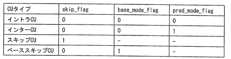
- a skip flag (skip_flag), a base mode flag (base_mode_flag), and a prediction mode flag (pred_mode_flag) may be encoded.
- the CU type of the target CU is an intra CU, an inter CU, a skip CU, or a base skip CU.
- Intra CU and skip CU can be defined in the same manner as in the HEVC method described above. For example, in the skip CU, “1” is set in the skip flag. If it is not a skip CU, “0” is set in the skip flag. In the intra CU, “0” is set in the prediction mode flag.
- the inter CU may be defined as a CU that applies non-skip and motion compensation (MC).
- MC non-skip and motion compensation
- the base skip CU is a CU type that estimates CU or PU information from a reference layer.
- “1” is set in the skip flag and “1” is set in the base mode flag.
- the PU type of the target PU is an intra PU, an inter PU, a merge PU, or a base merge PU.
- Intra PU, inter PU, and merge PU can be defined in the same manner as in the HEVC method described above.
- the base merge PU is a PU type for estimating PU information from a reference layer. Further, for example, in the PT information PTI, a merge flag and a base mode flag may be encoded, and using these flags, it may be determined whether or not the target PU is a PU that performs base merge. That is, in the base merge PU, “1” is set to the merge flag and “1” is set to the base mode flag.
- the motion vector information included in the enhancement layer the motion vector information that can be derived from the motion vector information included in the lower layer can be omitted from the enhancement layer.
- the code amount of the enhancement layer can be reduced, so that the coding efficiency is improved.
- the encoded data of the enhancement layer may be generated by an encoding method different from the encoding method of the lower layer. That is, the encoding / decoding process of the enhancement layer does not depend on the type of the lower layer codec.
- the lower layer is, for example, MPEG-2 or H.264. It may be encoded by the H.264 / AVC format.
- the reference layer parameters are converted to the corresponding parameters of the target layer or similar parameters, so that corresponding compatibility between the layers is achieved.
- the reference layer parameters can keep.
- a macroblock in the H.264 / AVC format can be interpreted as a CTB in HEVC.
- the parameters described above may be encoded independently, or a plurality of parameters may be encoded in combination.
- an index is assigned to the combination of parameter values, and the assigned index is encoded.
- the encoding of the parameter can be omitted.
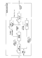
- FIG. 5 is a functional block diagram illustrating a schematic configuration of the hierarchical video decoding device 1.
- the hierarchical video decoding device 1 decodes the hierarchical encoded data DATA supplied from the hierarchical video encoding device 2 by the HEVC method, and generates a decoded image POUT # T of the target layer.
- the hierarchical video decoding device 1 includes a NAL demultiplexing unit 11, a variable length decoding unit 12, a prediction parameter restoration unit 14, a texture restoration unit 15, and a base decoding unit 16.
- the NAL demultiplexing unit 11 demultiplexes hierarchically encoded data DATA transmitted in units of NAL units in NAL (Network Abstraction Layer).
- NAL is a layer provided to abstract communication between a VCL (Video Coding Layer) and a lower system that transmits and stores encoded data.
- VCL Video Coding Layer
- VCL is a layer that performs video encoding processing, and encoding is performed in the VCL.
- the lower system here is H.264. H.264 / AVC and HEVC file formats and MPEG-2 systems are supported. In the example shown below, the lower system corresponds to the decoding process in the target layer and the reference layer.
- NAL a bit stream generated by VCL is divided into units called NAL units and transmitted to a destination lower system.
- the NAL unit includes encoded data encoded by the VCL and a header for appropriately delivering the encoded data to the destination lower system.
- the encoded data in each layer is stored in the NAL unit, is NAL multiplexed, and is transmitted to the hierarchical moving image decoding apparatus 1.
- the NAL demultiplexing unit 11 demultiplexes the hierarchical encoded data DATA, and extracts the target layer encoded data DATA # T and the reference layer encoded data DATA # R. Further, the NAL demultiplexing unit 11 supplies the target layer encoded data DATA # T to the variable length decoding unit 12, and also supplies the reference layer encoded data DATA # R to the base decoding unit 16.
- variable length decoding unit 12 performs a decoding process of information for decoding various syntax values from the binary included in the target layer encoded data DATA # T.
- variable length decoding unit 12 decodes the prediction information, the encoded information, and the transform coefficient information from the encoded data DATA # T as follows.
- variable length decoding unit 12 decodes prediction information regarding each CU or PU from the encoded data DATA # T.
- the prediction information includes, for example, designation of a CU type or a PU type.
- variable length decoding unit 12 decodes the PU partition information from the encoded DATA # T. In addition, in each PU, the variable length decoding unit 12 further converts motion information such as a reference image index RI, an estimated motion vector index PMVI, and a motion vector residual MVD, and mode information as encoded data DATA as prediction information. Decrypt from #T.
- variable length decoding unit 12 when the CU is an intra CU, the variable length decoding unit 12 further includes (1) size designation information for designating the size of the prediction unit and (2) prediction index designation for designating the prediction index as the prediction information.
- the intra prediction information including information is decoded from the encoded data DATA # T.
- variable length decoding unit 12 decodes the encoded information from the encoded data DATA # T.
- the encoded information includes information for specifying the shape, size, and position of the CU. More specifically, the encoding information includes tree block division information that specifies a division pattern of the target tree block into each CU, that is, the shape, size, and target tree block of each CU included in the target tree block. Contains information that specifies the position within.
- variable length decoding unit 12 supplies the decoded prediction information and encoded information to the prediction parameter restoration unit 14.
- variable length decoding unit 12 decodes the quantization prediction residual QD for each block and the quantization parameter difference ⁇ qp for the tree block including the block from the encoded data DATA # T.
- the variable length decoding unit 12 supplies the decoded quantization prediction residual QD and the quantization parameter difference ⁇ qp to the texture restoration unit 15 as transform coefficient information.
- the base decoding unit 16 decodes base decoding information, which is information about a reference layer that is referred to when decoding a decoded image corresponding to the target layer, from the reference layer encoded data DATA # R.
- the base decoding information includes a base prediction parameter, a base transform coefficient, and a base decoded image.
- the base decoding unit 16 supplies the decoded base decoding information to the prediction parameter restoration unit 14 and the texture restoration unit 15.
- the prediction parameter restoration unit 14 restores the prediction parameter using the prediction information and the base decoding information.
- the prediction parameter restoration unit 14 supplies the restored prediction parameter to the texture restoration unit 15.
- the prediction parameter restoration unit 14 can refer to motion information stored in a frame memory 155 (described later) included in the texture restoration unit 15 when restoring the prediction parameter.
- the texture restoration unit 15 generates a decoded image POUT # T using the transform coefficient information, the base decoding information, and the prediction parameter, and outputs the decoded image POUT # T to the outside.
- the texture restoration unit 15 stores information on the restored decoded image in a frame memory 155 (described later) provided therein.
- FIG. 6 is a functional block diagram illustrating the configuration of the prediction parameter restoration unit 14.
- the prediction parameter restoration unit 14 includes a prediction type selection unit 141, a switch 142, an intra prediction mode restoration unit 143, a motion vector candidate derivation unit 144, a motion information restoration unit 145, a merge candidate derivation unit 146, a merge An information restoration unit 147 and a PU partition type derivation unit 148 are provided.
- the prediction type selection unit 141 sends a switching instruction to the switch 142 according to the CU type or the PU type, and controls the prediction parameter derivation process. Specifically, it is as follows.
- the prediction type selection unit 141 controls the switch 142 so that the prediction parameter can be derived using the intra prediction mode restoration unit 143.
- the prediction type selection unit 141 uses the motion information restoration unit 145 to control the switch 142 so that a prediction parameter can be derived.
- the prediction type selection unit 141 uses the merge information restoration unit 147 to control the switch 142 so that the prediction parameter can be derived.
- the switch 142 supplies the prediction information to any of the intra prediction mode restoration unit 143, the motion information restoration unit 145, and the merge information restoration unit 147 in accordance with an instruction from the prediction type selection unit 141.
- a prediction parameter is derived at a supply destination of the prediction information.
- the intra prediction mode restoration unit 143 derives a prediction mode from the prediction information. That is, the intra prediction mode restoration unit 143 restores the prediction parameter in the prediction mode.
- FIG. 7 shows the definition of the prediction mode.
- 36 types of prediction modes are defined, and each prediction mode is specified by a number (intra prediction mode index) from “0” to “35”.
- the following names are assigned to each prediction mode. That is, “0” is “Intra_Planar (planar prediction mode, plane prediction mode)”, “1” is “Intra DC (intra DC prediction mode)”, and “2” to “34” are “ “Intra Angular (direction prediction)”, and “35” is “Intra From Luma”.
- “35” is unique to the color difference prediction mode, and is a mode for performing color difference prediction based on luminance prediction.
- the color difference prediction mode “35” is a prediction mode using the correlation between the luminance pixel value and the color difference pixel value.
- the color difference prediction mode “35” is also referred to as an LM mode.
- the number of prediction modes (intraPredModeNum) is “35” regardless of the size of the target block.
- the motion vector candidate derivation unit 144 uses the base decoding information to derive an estimated motion vector candidate by intra-layer motion estimation processing or inter-layer motion estimation processing.
- the motion vector candidate derivation unit 144 supplies the derived motion vector candidates to the motion information restoration unit 145.
- the motion information restoration unit 145 restores motion information related to each inter PU that is not merged. That is, the motion information restoring unit 145 restores motion information as a prediction parameter.
- the motion information restoration unit 145 restores motion information from the prediction information when the target CU (PU) is an inter CU (inter PU). More specifically, the motion information restoration unit 145 acquires a motion vector residual (mvd), an estimated motion vector index (mvp_idx), an inter prediction flag (inter_pred_flag), and a reference image index (refIdx). Then, based on the value of the inter prediction flag, a reference image list use flag is determined for each of the reference image list L0 and the reference image list L1.
- mvd motion vector residual
- mvp_idx estimated motion vector index
- inter_pred_flag inter prediction flag
- refIdx reference image index
- the motion information restoration unit 145 derives an estimated motion vector based on the value of the estimated motion vector index, A motion vector is derived based on the motion vector residual and the estimated motion vector.
- the motion information restoration unit 145 outputs the motion vector (motion compensation parameter) together with the derived motion vector, the reference image list use flag, and the reference image index.
- the merge candidate derivation unit 146 derives various merge candidates using the decoded motion information supplied from the frame memory 155 described later and / or the base decoding information supplied from the base decoding unit 16.
- the merge candidate derivation unit 146 supplies the derived merge candidates to the merge information restoration unit 147.
- the merge information restoration unit 147 restores motion information regarding each PU that is merged within a layer or between layers. That is, the motion information restoring unit 145 restores motion information as a prediction parameter.
- the merge information restoration unit 147 uses the merge candidate list derived by the merge candidate derivation unit 146 by intra-layer merging. Then, the motion information is restored by deriving a motion compensation parameter corresponding to the merge index (merge_idx) included in the prediction information.
- the merge information merging unit 146 derives a merge index (merge_idx) included in the prediction information from the merge candidate list derived by inter-layer merging.
- the motion information is restored by deriving the corresponding motion compensation parameter.
- the PU partition type derivation unit 148 estimates the PU partition type to the PU of the target CU in the target layer using the encoded information and the base decoding information.
- the PU partition type deriving unit 148 supplies the estimated PU partition type to the merge candidate deriving unit 146 and the merge information restoring unit 147.
- FIG. 9 is a functional block diagram illustrating the configuration of the texture restoration unit 15.
- the texture restoration unit 15 includes an inverse orthogonal transform / inverse quantization unit 151, a texture prediction unit 152, an adder 153, a loop filter unit 154, and a frame memory 155.
- the inverse orthogonal transform / inverse quantization unit 151 (1) inversely quantizes the quantized prediction residual QD included in the transform coefficient information supplied from the variable length decoding unit 12, and (2) obtained by inverse quantization.
- the DCT coefficient is subjected to inverse orthogonal transform (for example, DCT (Discrete Cosine Transform) transform), and (3) the prediction residual D obtained by the inverse orthogonal transform is supplied to the adder 153.
- inverse orthogonal transform for example, DCT (Discrete Cosine Transform) transform
- the inverse orthogonal transform / inverse quantization unit 151 derives a quantization step QP from the quantization parameter difference ⁇ qp included in the transform coefficient information.
- the texture prediction unit 152 refers to the base decoded image included in the base decoding information or the decoded decoded image stored in the frame memory according to the prediction parameter, and generates a predicted image.
- the texture prediction unit 152 includes an inter prediction unit 152A, an intra-layer intra prediction unit 152B, and an inter-layer intra prediction unit 152C.
- the inter prediction unit 152A generates a prediction image related to each inter prediction partition by inter prediction. Specifically, the inter prediction unit 152A generates a prediction image from the reference image using the motion information supplied as a prediction parameter from the motion information restoration unit 145 or the merge information restoration unit 147.
- the intra-layer intra prediction unit 152B generates a prediction image related to each intra-prediction partition by intra-layer intra prediction. Specifically, the intra-layer intra prediction unit 152B generates a prediction image from the decoded image that has been decoded in the target partition, using the prediction mode supplied from the intra prediction mode restoration unit 143 as a prediction parameter.
- the inter-layer intra prediction unit 152C generates a prediction image related to each intra prediction partition by inter-layer intra prediction. Specifically, the intra-layer intra prediction unit 152C generates a prediction image based on the base decoded image included in the base decoding information, using the prediction mode supplied from the intra prediction mode restoration unit 143 as a prediction parameter.
- the base decoded image may be appropriately upsampled according to the resolution of the target layer.
- the texture prediction unit 152 supplies the predicted image generated by the inter prediction unit 152A, the intra-layer intra prediction unit 152B, or the inter-layer intra prediction unit 152C to the adder 153.
- the adder 153 generates a decoded image by adding the prediction image of the texture prediction unit 153 and the prediction residual D supplied from the inverse orthogonal transform / inverse quantization unit 151.
- the loop filter unit 154 subjects the decoded image supplied from the adder 153 to deblocking processing and filtering processing using adaptive filter parameters.
- the frame memory 155 stores the decoded image that has been filtered by the loop filter unit 154.
- FIG. 10 is a functional block diagram illustrating the configuration of the base decoding unit 16.
- the base decoding unit 16 includes a variable length decoding unit 161, a base prediction parameter restoration unit 162, a base transform coefficient restoration unit 163, and a base texture restoration unit 164.
- variable length decoding unit 161 performs a decoding process of information for decoding various syntax values from the binary included in the reference layer encoded data DATA # R.
- variable length decoding unit 161 decodes prediction information and transform coefficient information from the encoded data DATA # R.
- the syntax of the prediction information and transform coefficients decoded by the variable length decoding unit 161 is the same as that of the variable length decoding unit 12, and therefore detailed description thereof is omitted here.
- variable length decoding unit 161 supplies the decoded prediction information to the base prediction parameter restoring unit 162 and also supplies the decoded transform coefficient information to the base transform coefficient restoring unit 163.
- the base prediction parameter restoration unit 162 restores the base prediction parameter based on the prediction information supplied from the variable length decoding unit 161.
- the method by which the base prediction parameter restoration unit 162 restores the base prediction parameter is the same as that of the prediction parameter restoration unit 14, and thus detailed description thereof is omitted here.
- the base prediction parameter restoration unit 162 supplies the restored base prediction parameter to the base texture restoration unit 164 and outputs it to the outside.
- the base transform coefficient restoration unit 163 restores transform coefficients based on the transform coefficient information supplied from the variable length decoding unit 161.
- the method by which the base transform coefficient restoration unit 163 restores the transform coefficients is the same as that of the inverse orthogonal transform / inverse quantization unit 151, and thus detailed description thereof is omitted here.
- the base conversion coefficient restoration unit 163 supplies the restored base conversion coefficient to the base texture restoration unit 164 and outputs it to the outside.
- the base texture restoration unit 164 uses the base prediction parameter supplied from the base prediction parameter restoration unit 162 and the base transform coefficient supplied from the base transform coefficient restoration unit 163 to generate a decoded image. Specifically, the base texture restoration unit 164 performs the same texture prediction as the texture prediction unit 152 based on the base prediction parameter, and generates a predicted image. Also, the base texture restoration unit 164 generates a prediction residual based on the base conversion coefficient, and generates a base decoded image by adding the generated prediction residual and the predicted image generated by texture prediction.
- the base texture restoration unit 164 may perform the same filter processing as the loop filter unit 154 on the base decoded image. Further, the base texture restoration unit 164 may include a frame memory for storing the decoded base decoded image, or may refer to the decoded base decoded image stored in the frame memory in texture prediction. Good.
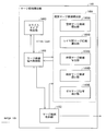
- FIG. 1 is a functional block diagram illustrating the configuration of the merge candidate derivation unit 146.
- the merge candidate derivation unit 146 includes a merge candidate derivation control unit (determination means) 1461, a merge candidate storage unit 1462, a slice type determination unit 1463, and an individual merge candidate derivation unit 1464.
- the merge candidate derivation control unit 1461 controls the individual merge candidate derivation unit 1464, derives a predetermined number (merge candidate derivation number) of merge candidates, and stores them in the merge candidate storage unit 1462.
- the merge candidate derivation number for example, the value of merge_idx + 1 is normally used. Note that an arbitrary integer greater than or equal to the value of merge_idx + 1 may be used as the merge candidate derivation number. For example, a value obtained by adding 1 to the maximum value of merge_idx may be used as MRG_MAX_NUM_CANDS as the merge candidate derivation number.
- the merge candidate storage unit 1462 stores a plurality of merge candidates. Merge candidates are recorded as an ordered list (merge candidate list).
- the slice type determination unit 1463 determines the slice type of the slice including the target PU in response to the request, and outputs the result.
- the individual merge candidate derivation unit 1464 derives and outputs merge candidates by a designated derivation method.
- the detailed operation of each merge candidate derivation unit selected based on the designated derivation method will be described later.
- the derived merge candidate is illustratively composed of a reference image list use flag (predFlagLX), a reference image index (refIdxLX), and a motion vector (mvLX) for the reference image list LX.
- predFlagLX a reference image list use flag
- refIdxLX reference image index
- mvLX motion vector
- the individual merge candidate derivation unit 1464 includes a spatial merge candidate derivation unit (target layer candidate derivation unit, spatial motion information candidate derivation unit) 1464A, an inter-layer merge candidate derivation unit (interlayer candidate derivation unit) 1464B, and time merge.
- the spatial merge candidate derivation unit 1464A and the temporal merge candidate derivation unit 1464C include the encoded parameters of the decoded CU and PU stored in the frame memory 155, in particular, motion in units of PUs. Compensation (motion compensation parameters) is provided.
- each merge candidate derivation unit derives merge candidates according to a predetermined priority order.
- the merge candidate derivation order is controlled by the merge candidate derivation control unit 1461.
- the merge candidate derivation control unit 1461 can cause each merge candidate derivation unit to derive arbitrary merge candidates excluding inter-layer merge candidates. Further, when performing inter-layer merging, the merge candidate derivation control unit 1461 can cause each merge candidate derivation unit to derive arbitrary merge candidates including inter-layer merge candidates.
- FIG. 11 is a diagram for explaining the operation of the spatial merge candidate derivation unit 1464A.
- FIG. 11 shows the positional relationship between the target PU and adjacent blocks A0, A1, B0, B1, and B2.
- the spatial merge candidate derivation unit 1464A outputs the motion compensation parameters in the adjacent blocks as merge candidates.
- the derivation order is A1, B1, B0, A0, and B2, for example.
- the derived merge candidates are stored in the merge candidate storage unit 1462. More precisely, the merge candidates are added to the end of the merge candidate list stored in the merge candidate storage unit 1462 in the derived order.
- each adjacent block can be expressed as follows, where the upper left coordinates of the PU are (xP, yP) and the PU sizes are nPSW and nPSH.
- B2 (xP-1, yP-1)
- N is any one of A0, A1, B0, B1, or B2
- the block at position N is not available (not available).
- the block at position N is intra-coded.
- N is B2 and all merge candidates corresponding to positions A0, A1, B0, and B1 are derived.
- the PU partition type is 2N ⁇ N or N ⁇ 2N, and the PU index is 1, and the PU of block N and index 0 has the same motion compensation parameter.
- N is B0 and block N and block B1 have the same motion compensation parameter.
- N is A0 and block N and block A1 have the same motion compensation parameter. If N is B2 and block N has the same motion compensation parameters as either block A1 or block B1.
- two blocks having the same motion compensation parameter means that the reference image list use flag, the reference image index, and the motion vector are all equal for both the reference image lists L0 and L1. The determination of the identity of motion compensation parameters (match determination) will be described in detail later.
- FIG. 12 is a diagram illustrating the operation of the inter-layer merge candidate derivation unit 1464B.
- FIG. 12 illustrates an area on the reference layer that is referred to when an inter-layer merge candidate is derived.
- the motion compensation parameter at the lower right position C0 in the region on the reference layer (hereinafter, abbreviated as the corresponding reference region) corresponding to the target PU is output as the merge candidate. Is done.
- the derived merge candidates are stored in the merge candidate storage unit 1462. More precisely, the merge candidates are added to the end of the merge candidate list stored in the merge candidate storage unit 1462 in the derived order.
- the inter-layer merge candidate derivation unit 1464B derives merge candidates by referring to the base decoding information as follows.
- the base decoding information referred to by the inter-layer merge candidate derivation unit 1464B includes reference layer motion compensation parameters (mxLX_RL, refIdxLX_RL, predFlagLX_RL).
- the merge candidate (merge candidate C0) output by the inter-layer merge candidate derivation unit 1464B is configured by motion compensation parameters (mvLX_C0, refIdxLX_C0, predFlagLX_C0).
- Upper left pixel position of the target prediction unit (xP, yP)
- the corresponding reference area is an area on the reference layer corresponding to the target PU.
- the spatial merge candidate is derived based on the position information of the upper right (B1, B0), lower left (A1, A0), and upper left (B2) of the target PU, whereas the inter-layer merge candidate is It is derived based on the information of the lower right (C0) position in the corresponding reference area.
- the merge candidate list includes various merge candidates having different properties from the spatial merge candidates.
- inter-layer merge candidate derivation unit 1464B may be able to derive a merge candidate from an arbitrary position in the corresponding reference region.
- the motion information decoded in the region on the reference layer corresponding to the region that has not been decoded in the target prediction unit may be derived as a merge candidate.
- inter-layer merge candidate derivation unit 1464B may derive based on information on a position adjacent to any of the lower right (C0) right, lower, and lower right.
- the inter-layer merge candidate derivation unit 1464B may be able to derive a merge candidate from a position on the reference layer corresponding to a position near the region R1 of the target PU illustrated in FIG.
- the region R1 can be expressed as a region in a predetermined range including the lower right position in the target reference region.
- a merge candidate having a property different from that of the spatial merge candidate can be derived from the position in the corresponding reference region as the inter-layer merge candidate.
- Supplementing the undecrypted area is as follows.
- tree blocks are decoded in raster scan order starting from the upper left corner of the picture and moving in the lower right direction.
- a tree block subsequent to the target tree block including the target prediction unit in the raster scan order is an undecoded region.
- the tree block located below the target tree block or the tree block whose vertical position is the same as the target tree block and located right of the target tree block has not been decoded yet. It is.
- the area included in the undecoded tree block is an undecoded area.
- the CU in the tree block is processed in the so-called Z-scan order.
- the tree block is divided into four congruent squares, and processing is performed in the order of the CUs included in the upper left, upper right, lower left, and lower right square regions. Subsequently, processing is also performed recursively for each square area.
- the upper left area is further divided into four congruent square areas, and CUs included in each square area are processed in the order of upper left, upper right, lower left, and lower right.
- the numbers assigned to the respective regions represent the scan order by Z scan.
- the upper left area obtained by dividing the tree block into four includes 1 to 7 CUs, 8 CUs in the upper right area, 9 CUs in the lower left area, and 10 to 13 CUs in the lower right area.
- the upper left area including 1 to 7 CUs is further divided into four, and the upper left area includes 1 CU, the upper right area includes 2 CUs, the lower left area includes 3 CUs, and the lower right area includes 4 to 7 CUs.
- a CU after the target CU in the Z-scan order is a CU that has not been decoded, and a region included in the CU is a region that has not been decoded.
- inter-layer merge candidate derivation unit 1464B may be restricted or prohibited from deriving merge candidates from a specific position.
- motion information corresponding to the lower right (C0) position in the corresponding reference area is not recorded in the memory.
- information corresponding to a position near the lower right (C0) is used.
- merge candidates may be derived. For example, when the motion information of the reference layer is recorded by being thinned out at a specific interval (N pixel unit), it is changed to the position of C0, that is, the position of (xC0, yC0) ((xC0 // N) * The merge candidate may be derived based on motion information corresponding to the position of N, (yC0 // N) * N).
- the operator “//” is an operator whose value of “x // y” is a quotient obtained by dividing x by y.
- FIG. 13 is a diagram for explaining the operation of the time merge candidate derivation unit 1464C.
- the temporal merge candidate derivation unit 1464C generally derives the temporal merge candidate as follows. That is, when the current picture is currPic, the temporal merge candidate deriving unit 1464C occupies the PU on the reference image specified by the reference image index refIdxL0 that occupies substantially the same spatial position as the target PU in the current picture.
- the temporal merge candidate is derived by copying the motion compensation parameter of the PU on the reference image specified by the reference image index refIdxL1.
- the reference index number refIdxLX (where X is 0, 1 or C) is obtained as follows using the reference pictures refIdxLXA, refIdxLXB, and refIdxLXC of the adjacent PU, A, B, and C blocks of the target PU.
- refIdxLX refIdxLXA
- refIdxLXB refIdxLXC
- refIdxLX refIdxLXA
- refIdxLXB refIdxLXC
- the coordinates of the blocks A and B are as follows.
- the coordinates of the block C are any of the following C0, C1, and C2. If the PU corresponding to each position is available and other than intra, the refIdxLX of the PU at that position is set as refIdxLXC.
- the L1 motion vector MvL1 of the PU is used as the temporal merge candidate LX motion vectors mvLXCol [0] and mvLXCol [1].
- the L0 motion vector MvL0 of the PU is used as the temporal merge candidate LX motion vectors mvLXCol [0] and mvLXCol [1].
- the motion vector mvLXCol is scaled using the POC (Picture Order Count) of the current frame and the POC of the reference picture to obtain a final temporal merge candidate.
- the time merge candidate derivation unit 1464C stores the derived time merge candidate in the merge candidate storage unit 1462.
- the merge merge candidate deriving unit 1464D derives a merge merge candidate by combining motion vectors of two different derived merge candidates already derived and stored in the merge candidate storage unit 1462.
- the merge merge candidate derivation unit 1464D increments the merge merge candidate count combCnt from 0, and merges until the number of elements in the merge candidate list matches the merge candidate derivation number, or until combCnt exceeds the maximum value (5). Candidates are derived and added to the end of the merge candidate list.
- the procedure for deriving the merge merge candidate corresponding to the specific merge merge candidate count combCnt is as follows.
- the merge candidate combination list is referred to with combCnt as an index (combIdx), and two merge candidates used for the combination, that is, indexes l0CandIdx and L1CandIdx indicating the positions of the L0 merge candidate and the L1 merge candidate on the merge candidate list, respectively
- combIdx indexes l0CandIdx and L1CandIdx indicating the positions of the L0 merge candidate and the L1 merge candidate on the merge candidate list, respectively
- An example of the merge candidate combination list is shown in FIG.
- the merge merge candidate is generated by copying the motion compensation parameters of the L0 merge candidate to the reference image list L0 and the L1 merge candidate to the reference image list L1. Note that when any of the following conditions is satisfied, a merge merge candidate corresponding to combCnt is not derived.
- -L0 reference image list use flag of L0 merge candidate is 0 -L1 reference image list use flag of L1 merge candidate is 0
- the motion vectors or reference images of the L0 merge candidate and the L1 merge candidate match.
- the combined merge candidate is derived by the above procedure.
- both the L0 and L1 reference image list use flags are 1. That is, the merge merge candidate is a merge candidate that performs bi-prediction.
- merge merge candidates are not included in the merge candidate list.
- FIG. 15 is a diagram illustrating the operation of the zero merge candidate derivation unit 1464E. If the number of merge candidates in the merge candidate storage unit 1462 reaches the number of merge candidate derivations, the zero merge candidate derivation unit 1464E does not perform processing (zero merge candidates are not derived). On the other hand, if the number of merge candidates does not reach the number of merge candidate derivations, the zero merge candidate derivation unit 1464E generates a merge candidate having a zero vector until the number of merge candidates reaches the number of merge candidate derivations to generate a merge candidate list. Add to.
- the index of the merge candidate to be referenced is zeroCand m
- the L0 motion vector (mvL0zeroCand m [0], mvL0zeroCand m [1]) and the L1 motion vector (mvL1zeroCand m [0], mvL1zeroCand m [1]) are both A candidate such as 0 is derived.
- the index zeroCand m uses a value obtained by adding 1 to the value of the last index of the merge candidate list already derived.
- m is an index starting from 0, and is incremented by 1 when a zero merge candidate is added to the merge candidate list.
- FIG. 16 is a flowchart illustrating an example of the operation flow of the merge candidate derivation unit 146.
- the merge candidate C0 is derived in the inter-layer merge candidate derivation unit 1464B (S102).
- the merge candidate T is derived in the time merge candidate derivation unit 1464C (S103).
- the merge candidate C is derived in the merge merge candidate deriving unit 1464D (S104).
- S104 may be configured to be executed when the slice type determination unit 1463 determines that the slice type is a B slice.
- the merge candidate Z is derived in the zero merge candidate deriving unit 1464E (S105).
- the hierarchical video decoding device 1 decodes the hierarchically encoded data DATA in which image information relating to images of different quality for each layer is hierarchically encoded, and the target layer to be decoded Is a hierarchical video decoding device 1 that restores the decoded image POUT # T in the target layer using a predicted image generated by motion compensated prediction based on the restored motion information.
- a reference layer that is a decoded layer is referred to, and decoding is performed in a region on the reference layer that corresponds to an undecoded region in a peripheral region that includes the target prediction unit
- Inter-layer merge candidate derivation unit 146 that derives motion information as a candidate for estimating motion information in the target prediction unit. It is configured to include B.
- motion information on a reference area corresponding to an area that cannot be used because it is not decoded in the same layer can be added to the merge candidate list.
- the inter-layer merge candidate derivation unit 1464B may derive inter-layer merge candidates from two or more positions on the reference area.
- FIGS. 17A to 17C will be described in order.
- the inter-layer merge candidate derivation unit 1464B may further target the inter-layer merge candidate derivation in addition to the position C0 in the upper left position C1 in the corresponding reference region.
- the inter-layer merge candidate derivation unit 1464B uses the position C1 when the position C0 is unavailable. That is, as the priority of merge candidate derivation by the inter-layer merge candidate derivation unit 1464B, the lower right position C0 has priority over the position C1.
- the inter-layer merge candidate deriving unit 1464B may be able to derive the inter-layer merge candidate even when the motion information at the position C0 cannot be referred to because the position C0 cannot be used.
- the inter-layer merge candidate derivation unit 1464B merges the lower right adjacent blocks C0, C2, and C3 of the corresponding reference area and the upper left position C1 of the corresponding reference area. It may be used for derivation of candidates. It should be noted that the priority order for merging candidate derivation is illustratively in the order of positions C0, C1, C2, and C3.
- the pixel corresponding to the upper left position and the pixel corresponding to the lower right position in the corresponding reference area belong to the same motion information recording unit.
- Using the motion information of the lower right adjacent block increases the possibility that the motion information can be derived from a recording unit different from the upper left portion in the corresponding reference area.
- the inter-layer merge candidate derivation unit 1464B has a lower right position C0 in the corresponding reference area, a lower right adjacent block C1 in the corresponding reference area, and an upper left position C1 in the corresponding reference area.
- the right adjacent block C3 and the lower adjacent block C4 of the corresponding reference region may be used for deriving inter-layer merge candidates.
- the priorities for deriving merge candidates may be the order of positions C0, C1, C2, C3, and C4.
- merge candidate derivation control unit 1461 when merge candidate derivation control unit 1461 performs a match determination between each of the motion compensation parameters at positions C1 to C4 and the motion compensation parameter at position C0, as a result of the determination, the motion compensation parameters do not match.
- the inter-layer merge candidate derivation unit 1464B may derive a corresponding merge candidate.
- the operation of the function equalMotion (A, B) for determining whether the motion compensation parameters of the blocks A and B match each other can be specified as follows.
- predFlagL0A and predFlagL1A are 1 when the reference pictures L0 and L1 are used in the block A, respectively, and 0 otherwise.
- mvL0 [0] and mvL0 [1] are the horizontal motion vector and vertical motion vector of L0
- mvL1 [0] and mvL1 [1] are the horizontal motion vector and vertical motion vector of L1.
- A is replaced with B.
- inter-layer merge candidate derivation unit 1464B derives merge candidates in the order of priority while performing the above-described matching determination, and adds inter-layer merge candidates until the number of unique merge candidates becomes two. Also good.
- the possibility that different motion information can be derived increases, so that the possibility that the motion information to be encoded is included in the merge candidate increases. As a result, the amount of code of motion information can be reduced.
- the merge candidate derivation control unit 1461 may perform match determination of motion compensation parameters of merge candidates derived by each merge candidate derivation unit (hereinafter referred to as merge candidate match determination). Further, the merge candidate derivation control unit 1461 may store only the merge candidates determined to be unique as a result of the match determination in the merge candidate storage unit 1462. Further, the merge candidate derivation control unit 1461 may omit the determination of matching between the inter-layer merge candidate derived by the inter-layer merge candidate derivation unit 1464B and the merge candidate derived by another merge candidate derivation unit.
- the temporal merge candidate derivation unit 1464C and the merged merge candidate derivation unit 1464D derive merge candidates after the inter-layer merge candidate derivation unit 1464B.
- the inter-layer merge candidate derivation step (S102), the temporal merge candidate derivation step (S103), and the merged merge candidate derivation step (S104) can be executed in parallel.
- the merge candidate derivation control unit 1461 when performing a match determination between the spatial merge candidate and the inter-layer merge candidate, performs a match determination only with the merge candidate S0 of the spatial merge candidate (the first merge candidate in the merge candidate list). Preferably it is done.
- FIG. 18 is a flowchart illustrating another example of the operation of the merge candidate derivation unit 146.
- the merge candidate S0 to merge candidate S2 are derived in the spatial merge candidate derivation unit 1464A (S201).
- the merge candidate derivation control unit 1461 determines whether or not the inter-layer merge candidate derivation is valid (S202).
- the merge candidate derivation control unit 1461 can determine that the inter-layer merge candidate derivation is effective in the following case (A) or (B), for example.
- A When a flag included in SPS or PPS indicates that inter-layer merge prediction is valid; or (B) A reference layer corresponding to the target PU exists, and the target PU and the reference layer are P slices or B slices.
- the inter-layer merge candidate derivation unit 1464B derives the merge candidate C0 (S204).
- the merge candidate T is derived in the temporal merge candidate derivation unit 1464C (S203).
- inter-layer merge candidate step (S204) and the temporal merge candidate derivation step (S203) are performed alternatively, when one of the two is executed, the other is omitted.
- merge candidate C is derived in combined merge candidate derivation unit 1464D (S205).
- merge candidate Z is derived in the zero merge candidate derivation unit 1464E (S206).
- the code amount reduction width of the motion information when the temporal merge candidate and the inter-layer merge candidate are used together is not significantly different from the code amount reduction width of the motion information when either one is used.
- the code amount does not increase so much even if the temporal merge candidate is not used. Furthermore, if the derivation of the time merge candidate is omitted, the processing load related to the derivation of the time merge candidate can be reduced, and the memory resource can be saved.
- the time merge candidate is not used when the inter-layer merge candidate is used.
- the individual merge candidate derivation unit 1464 may further include an inter-layer intra candidate derivation unit 1464F.
- the inter-layer intra candidate derivation unit 1464F signals inter-layer intra prediction (texture prediction) in the merge candidate list.
- the inter-layer intra candidate derivation unit 1464F adds an inter-layer intra candidate that is a candidate for signaling inter-layer intra prediction to the merge candidate list.
- the inter-layer intra prediction unit 152C of the texture prediction unit 152 generates a prediction image based on the image obtained by up-sampling the decoded pixels of the reference layer.
- the merge candidate derivation control unit 1461 may add each merge candidate to the merge candidate list in the following priority order.
- the merge candidate derivation unit 146 derives the merge candidate For example, it can be performed by the following method.
- merge candidates are added in the priority order of 1) to 6) until the maximum number of merge candidate derivations in the merge candidate list is reached.
- Another method is to add the merge candidate derived from the maximum number of merge candidates derived in the merge candidate list in the priority order of 1) to 5) minus one, and then 6) merge candidates between layers as merge candidates. Add as
- intra-layer intra prediction can be selected in units of PUs. Thereby, compared with the case where a selection flag (base_mode_flag) is provided for every CU, side information can be reduced.
- the merge candidate derivation control unit 1461 may add each merge candidate to the merge candidate list in the following priority order.
- Inter-layer candidate is a merge candidate related to inter-layer prediction. Is an inter-layer merge candidate or an inter-layer intra candidate. A candidate to be added as an inter-layer candidate according to a prediction type of a CU (hereinafter referred to as a reference CU) to which a region on a reference layer corresponding to the target PU belongs is between an inter-layer merge candidate and an inter-layer intra candidate. Can be switched. This switching may be controlled by the merge candidate derivation control unit 1461.
- the inter-layer merge candidate derivation unit 1464B derives the inter-layer merge candidate as an inter-layer candidate.
- the inter prediction unit 152A of the texture prediction unit 152 generates a prediction image by motion compensation prediction.
- the inter-layer intra candidate derivation unit 1464F derives the inter-layer intra candidate as an inter-layer candidate.
- the inter-layer intra prediction unit 152C of the texture prediction unit 152 generates a prediction image based on an image obtained by up-sampling the decoded pixels of the reference layer.
- the decoded image of the inter CU is not used for motion information prediction in inter-layer prediction in order to reduce the processing amount in the motion compensation process. Further, when the reference layer is an intra CU, there is no motion compensation information in the intra CU.
- candidates are generated using information available in the reference CU depending on whether the reference CU is an inter CU or an intra CU.
- the number of merge candidates can be reduced as compared with the case where the inter-layer merge candidate and the inter-layer intra candidate are different candidates.
- FIG. 27 is a functional block diagram illustrating the configuration of the PU partition type deriving unit 148.
- the PU partition type deriving unit 148 includes a reference CU setting unit 1481 and a PU partition estimation unit 1482.
- the reference CU setting unit 1481 sets an area on the reference layer corresponding to the target CU when decoding the target CU to be decoded, and refers to the set reference area at the time of PU partition estimation. Set the CU on the power reference layer.
- the region set by the reference CU setting unit 1481 is referred to as a reference region, and the CU on the reference layer is referred to as a reference CU.
- the PU partition estimation unit 1482 refers to the reference CU set by the reference CU setting unit 1481, and estimates the partition type (estimated PU partition type) into PUs in the target CU of the target layer.
- the PU partition estimation unit 1482 includes a lower right pixel position determination unit 1482A, an overlap region determination unit 1482B, and a partition type determination unit 1482C.
- the lower right pixel position determination unit 1482A determines the position of the position of the lower right pixel in the reference CU within the reference area.
- the overlapping area determination unit 1482B determines the degree of overlapping of an area where the reference CU and the reference area overlap (hereinafter referred to as an overlapping area).
- the overlapping degree of the overlapping region includes, for example, the size of the overlapping region, the size of the overlapping region, the relationship between the width and the height, and the inclusion relationship between the reference CU and the reference region.
- the division type determination unit 1482C determines the PU division type in the target CU according to the determination result of the lower right pixel position determination unit 1482A or the overlapping region determination unit 1482B.
- the reference CU setting unit 1481 sets a reference region refREG on the reference layer corresponding to the target CUtgtCU, which is a CU included in the reference frame refFR1 on the reference layer.
- the reference frame refFR1 is illustratively a frame on the reference layer at the same time as the target frame tgtFR1.
- the target CUtgtCU “corresponds” to the reference region refREG means that the spatial position of the target CUtgtCU in the target frame tgtFR1 on the target layer is the spatial position of the reference region refREG in the reference frame refFR1 on the reference layer. It means that it corresponds.
- the reference CU setting unit 1481 sets a reference CU based on the reference area refREG.
- the coding area block refCTB1 on the reference layer includes the reference region refREG.
- the coding tree block refCTB1 includes refCU0, refCU1, refCU2, and refCU3, which are CUs having a hierarchical depth of 1.
- refCU0 includes refCU00, refCU01, refCU02, and refCU03, which are split CUs with a hierarchical depth of 2.
- the reference region refREG has an overlapping portion with a plurality of CUs on the reference layer. That is, the reference area refREG may overlap with a plurality of CUs on the reference layer.
- the reference area refREG has an overlapping portion with refCU00, refCU01, refCU02, refCU03, refCU1, refCU2, and refCU3.
- the reference CU setting unit 1481 mainly sets the CU on the reference layer including the pixel refCUPX corresponding to the upper left pixel tgtCUPX of the target CU as the reference CU will be described. That is, in the example shown in FIG. 28, refCU00 is the reference CU.
- the height and width of the target frame tgtFR1 on the target layer are hPic and wPic, respectively.
- the height and width of the target CUtgtCU are hCu and wCu, respectively, and the coordinate representation in the target frame tgtFR1 at the position of the upper left pixel is (xCu, yCu).
- the height and width of the reference frame refFR1 on the reference layer are set to hRefPic and wRefPic, respectively.
- the reference CU setting unit 1481 sets the reference CU as follows. First, the reference CU setting unit 1481 derives the coordinates (xRefReg, yRefReg) of the reference region refREG by the following calculation. Note that scaleX and scaleY below are the ratios of the width and height of the target frame to the width and height of the reference frame.
- the reference CU setting unit 1481 sets a CU including the coordinates (xRefReg, yRefReg) of the reference region refREG obtained as described above as a reference CU.
- the reference CU setting unit 1481 is not limited to the above, and may set the reference CU corresponding to the center pixel as follows. First, the reference CU setting unit 1481 derives the width and height (wRefReg, hRefReg) of the reference region refREG by the following calculation. Note that the method for deriving scaleX, scaleY, xRefRegx and yRefReg shown below is as described above.
- the reference CU setting unit 1481 sets the CU including the coordinates (xRefC, yRefC) of the center pixel of the reference area obtained as described above as a reference CU.
- the values of scaleX and scaleY are calculated on the assumption that the entire reference frame on the reference layer and the entire target frame on the target layer correspond spatially, but are not limited thereto.
- a case where the partial region on the target layer spatially corresponds to the entire reference frame on the reference layer can be considered.
- the values of scaleX and scaleY are calculated based on the position of the partial area on the target layer (offset from the upper left of the target frame) and the size of the partial area.
- the lower right pixel position determination unit 1482A determines the position of the lower right pixel refCUPX of the reference CUrefCU in the reference region refREG, and based on the determination result, the division type determination unit 1482C determines the PU partition type in the target CU.
- the upper left pixel of the reference area refREG is included in the reference CUrefCU.
- Lower right pixel is upper half of reference area As shown in FIG. 30A, the position of the lower right pixel refCUPX of the reference CUrefCU is positioned at the upper half of the reference area refREG (area above the straight line M1).
- the PU partition type in the target CUtgtCU is estimated to be 2N ⁇ N (see FIG. 30B).
- Lower right pixel is lower right of reference area
- the position of the lower right pixel refCUPX of the reference CUrefCU is a lower right position in the reference area refREG (below the straight line M1 and a straight line).
- the division type determination unit 1482C estimates the PU division type in the target CUtgtCU as 2N ⁇ 2N (see FIG. 32B).
- Reference CU includes reference area As shown in FIG. 33A, when it is determined that the position of the lower right pixel refCUPX of the reference CUrefCU is at the lower right position outside the reference area refREG, that is, reference When the CUrefCU includes the reference region refREG, the division type determination unit 1482C estimates the PU division type in the target CUtgtCU as 2N ⁇ 2N (see FIG. 32B).
- the reference CU When the reference CU includes a reference area, there is a high possibility of having uniform motion information within the reference area. For this reason, encoding efficiency can be improved by using 2N ⁇ 2N, which is the most suitable PU partition when there is uniform motion in the reference region.
- the PU partition type can be derived by the position determination process of the lower right pixel without strictly deriving the position of the CU boundary in the reference region. Thereby, it is possible to derive the PU partition type with a relatively small processing amount.
- the position of the upper left pixel of the reference region refREG is (xRefReg, yRefReg), and the size of the reference region refREG is wRefReg ⁇ hRefReg. Further, the position of the lower right pixel refCUPX of the reference CUrefCU is assumed to be (xRefCUBR, yRefCUBR).
- FIG. 35 is a diagram illustrating the relationship between the position of the lower right pixel refCUPX of the reference CUrefCU and the determination result.
- the lower right pixel position determination unit 1482A determines whether the expression (A1) is true or false.
- the lower right pixel position determination unit 1482A further determines the authenticity of the expression (A2).
- the lower right pixel position determination unit 1482A determines the authenticity of the expression (A3).
- Reference CU includes reference region
- expression (A3) is false
- lower right pixel position determination unit 1482A further determines the authenticity of expression (A4).
- the position of the upper left pixel of the reference region refREG is (xRefReg, yRefReg). Further, the position of the lower right pixel refCUPX of the reference CUrefCU is assumed to be (xRefCUBR, yRefCUBR). Further, the position of the lower right pixel of the reference area refREG is (xRefRegBR, yRefRegBR), and the position of the upper left pixel of the reference CUrefCU is (xRefCU, yRefCU).
- Reference CUrefCU includes reference region refREG
- reference region refREG when it is determined that reference CUrefCU includes reference region refREG (when reference region refREG matches the overlapping region), division The type determination unit 1482C estimates the PU partition type in the target CUtgtCU as 2N ⁇ 2N (see FIG. 36B). In the determination, for example, the position of the upper left pixel of the reference CUrefCU is compared with the position of the upper left pixel of the reference area refREG, and the width and height of the reference CUrefCU are compared with the width and height of the reference area refREG. This can be done.
- width (wOver) of the overlapping area and the width (hOver) of the overlapping area may be calculated and the determination may be performed based on these values.
- wOver and hOver can be calculated using the following equations.
- wOver Min (xRefRegBR, xRefCuBR)-Max (xRefReg, xRefCu)
- hOver Min (yRefRegBR, yRefCuBR)-Max (yRefReg, yRefCu)
- the values of wOver and hOver can be calculated by a simplified calculation. For example, when the reference CUrefCU includes the upper left pixel of the reference area refREG, the upper left pixel of the reference CUrefCU is always located at the upper left than the upper left pixel of the reference area refREG. Therefore, in such a case, the values of wOver and hOver can be calculated by the following equations, respectively.
- the division type determination unit 1482C estimates the PU division type in the target CUtgtCU as 2N ⁇ N (see FIG. 37C).
- wOver is abbreviated as “w”
- hOver is abbreviated as “h”.
- the overlapping area determination unit 1482B determines whether the expression (B1) is true or false.
- the division type determination unit 1482C estimates the PU division type in the target CUtgtCU as N ⁇ 2N (see FIG. 38C).
- the overlapping area determination unit 1482B may determine that the width of the overlapping area is less than the height when the formula (B1) is false.
- the position of the upper left pixel (xRefReg, yRefReg) of the reference area refREG and the position of the lower right pixel refCUPX (xRefCUBR, yRefCUBR) of the reference CUrefCU are set as comparison targets.
- the present invention is not limited to this, and the above determination can also be applied to the case where a reference CU corresponding to a pixel position other than the upper left pixel of the reference region refREG is used.
- the hierarchical moving image decoding apparatus 1 decodes hierarchically encoded data in which image information related to images of different quality for each layer is hierarchically encoded, in the target layer to be decoded.
- the hierarchical video decoding device 1 for restoring an image, wherein a target CU in the target layer overlaps with the reference region based on a CU having an overlapping portion with a reference region corresponding to the target CU in the reference layer.
- the division type determination unit 1482C may perform a determination using the PU division type of the reference CU.
- the division type determination unit 1482C determines the PU partition type of the target CU without using the PU partition type of the reference CU.
- division type determination part 1482C determines the PU division type of object CU as follows using the PU division type of reference CU. That is, [D1] When the PU partition type of the reference CU is 2N ⁇ 2N: The division type determination unit 1482C determines the PU division type of the target CU as 2N ⁇ 2N.
- the division type determination unit 1482C determines the PU division type of the target CU as 2N ⁇ N.
- the division type determination unit 1482C determines the PU division type of the target CU as N ⁇ 2N.
- the division type determination unit 1482C determines the PU partition type in the target CU by strictly calculating the position of the PU boundary in the reference CU. It may be a configuration. Hereinafter, a configuration example of such a division type determination unit 1482C will be shown.
- division type determination part 1482C determines the PU division type of object CU as follows using the PU division type of reference CU. That is, [D1] When the PU partition type of the reference CU is 2N ⁇ 2N: The division type determination unit 1482C determines the PU division type of the target CU as 2N ⁇ 2N.
- the position of the upper left pixel of the reference CUrefCU is (xRefCu, yRefCu), and the height and width of the reference CUrefCU are hRefCu, wRefCu, respectively.
- the reference position of the PU boundary in the reference CUrefCu is a position (xRefCu, yPub) where the left side of the reference CU intersects the PU boundary (yPub is the position of the vertical PU boundary).
- the position of the upper left pixel of the reference area refREG is (xRefReg, yRefReg), and the height and width of the reference area are hRefReg and wRefReg, respectively.
- the division type determination unit 1482C derives the position yPub in the y direction of the horizontal PU boundary as follows.
- the division type determination unit 1482C determines the PU division type as 2N ⁇ 2N.
- the division type determination unit 1482C determines the PU division type as 2N ⁇ nU.
- the division type determination unit 1482C strictly calculates the position of the PU boundary (that is, the position of the vertical PU boundary) in the reference CU.
- the calculation method the calculation method shown in FIG. 40 applied to the vertical PU boundary can be used, and thus detailed description thereof is omitted.
- the division type determination unit 1482C increases or decreases the size of the reference CU and the size of the target CU.
- the PU partition type may be determined accordingly.
- the division type determination unit 1482C may determine the PU division type as 2N ⁇ 2N.
- the division type determination unit 1482C may set the PU division type of the reference CU as the PU division type.
- the determination process can be simplified.
- the division type determination unit 1482C may be configured to always use 2N ⁇ 2N as the PU division type in a predetermined size CU (for example, 8 ⁇ 8 CU). That is, the division type determination unit 1482C may prohibit division in a CU having a predetermined size.
- the partition type determination unit 1482C may derive only a symmetric partition as a PU partition type in a CU having a predetermined size. Further, the division type determination unit 1482C may limit deriving N ⁇ N as a PU division pattern.
- the partition type determining unit 1482C may be configured not to derive the asymmetric partition as the PU partition type. For example, when estimating the PU partition type of the target CU from the PU partition type of the reference CU, the partition type determining unit 1482C may be configured to derive a symmetric partition according to the directionality of the boundary as the PU partition type.
- the determination using the PU partition type of the reference CU described above is not limited to [D] but can also be applied to [A] to [C].
- the partition type determination unit 1482C may derive a symmetric partition as a PU partition type.
- the reference CU setting unit 1481 may be configured to set a single reference CU based on a predetermined criterion from among a plurality of CUs having an overlapping portion with the reference region refREG.
- the reference CU setting unit 1481 may set a CU on a reference layer including a pixel corresponding to a pixel at a predetermined position included in the target CU among the plurality of CUs as the reference CU.
- the reference CU setting unit 1481 may set a CU on the reference layer including a pixel corresponding to the central pixel included in the target CU as the reference CU.
- the reference CU setting unit 1481 may use, as a reference CU, a CU having the largest area among a plurality of CUs having overlapping portions with the reference region refREG.
- the CU on the reference layer including the pixel corresponding to the central pixel included in the target CU, or the CU having the largest area among the plurality of CUs may be the same PU partition type as the target CU. Therefore, the estimation accuracy can be improved.
- the reference CU setting unit 1481 may generate a virtual single CU from a plurality of CUs having an overlapping portion with the reference region refREG. Specifically, the reference CU setting unit 1481 extracts representative properties in a plurality of CUs from CUs around the reference region, generates a virtual single CU based on the extracted properties, and generates a reference code. It may be a unit. For example, the reference CU setting unit 1481 can generate the virtual single CU based on the size and shape of a plurality of CUs or by combining these pieces of information. The virtual single coding unit is generated so as to be an area overlapping the reference area.
- the reference CU setting unit 1481 may use a plurality of CUs having overlapping portions with the reference region refREG as a reference CU list.
- the PU partition estimation unit 1482 has been described as a configuration including both the lower right pixel position determination unit 1482A and the overlapping region determination unit 1482B.
- the PU partition estimation unit 1482 may be configured to include one of the lower right pixel position determination unit 1482A and the overlap region determination unit 1482B.
- estimation other than the PU partition type (for example, pred_mode) may be executed depending on the syntax configuration.
- FIG. 42 shows a configuration example of the syntax when base_mode_flag is encoded with coding_unit.
- base_mode_flag may be encoded immediately after skip_flag in coding_unit (SYN11).
- SYN11 coding_unit
- the base mode flag (base_mode_flag) is arranged after the skip flag (skip_flag) and before the prediction mode flag (pred_mode_flag).
- base_mode_flag base_mode_flag
- prediction mode flag pred_mode_flag
- partition type partition type
- the decoding in the base skip CU (decoding related to base_mode_flag) is performed as follows.
- the hierarchical video decoding device 1 decodes base_mode_flag.
- the hierarchical video decoding device 1 decodes the syntax element values of pred_mode_flag and part_mode from the encoded data, and based on the decoded syntax value, PredMode And PartMode are derived.
- FIG. 41 is a table showing the relationship between syntax element values and CU types.
- “-” indicates a syntax element that does not need to be decoded in the CU type.
- the hierarchical video decoding device 1 may always use intra prediction (MODE_INTRA) in the target CU.
- the hierarchical video decoding device 1 may use the PredMode of the reference CU.
- a CU on the reference layer including the upper left pixel of the target CU can be used as the reference CU.
- the hierarchical video decoding device 1 may always use intra prediction (MODE_INTRA) in the target CU.
- the hierarchical video decoding device 1 uses inter prediction (MODE_INTER).
- the condition “when the base layer is not an I slice” may be the condition “when the base layer is IDR (Instantaneous Decoding
- IDR is initialization of a reference picture, and an IDR picture is a picture whose reference has been reset. That is, in an IDR picture, pictures subsequent to that picture can be correctly decoded without referring to information prior to that picture (slice).
- FIG. 43 shows a configuration example of syntax when encoding merge_flag after determining base_mode_flag in prediction_unit.
- base_mode_flag may be determined immediately before mereg_flag in prediction_unit (SYN 21). Further, when base_mode_flag is “true”, merge_flag need not be arranged.
- the three flags pred_mode, part_mode, and merge_flag can be omitted. Thereby, the code amount of these three flags can be reduced, and the encoding efficiency is improved.
- FIGS. 44, 45, and 46 are flowcharts illustrating examples of the flow of the decoding process regarding the prediction parameters of the base skip CU, the skip CU, and the inter CU, respectively.
- the reference CU setting unit 1481 sets a reference CU corresponding to the target CU (S301).
- the PU partition estimation unit 1482 estimates the PU partition type in the target CU by inter-layer prediction (S302). Specifically, the PU partition type is estimated by the partition type determination unit 1482C based on the determination result in the lower right pixel position determination unit 1482A or the determination result in the overlap region determination unit 1482B.
- the merge candidate derivation unit 146 derives a merge candidate list for the target PU (S304).
- the merge candidate derivation unit 146 derives an inter-layer merge candidate in derivation of the merge candidate list.
- the inter-layer prediction can be arbitrarily set.
- only the PU partition type may be the target of inter-layer prediction. That is, it is possible to adopt a configuration in which only the intra-layer merge candidates are derived in S304.
- the merge information restoration unit 147 selects a merge candidate from the derived merge candidate list (S305).
- the prediction parameter restoration unit 14 sets the PU partition type to 2N ⁇ 2N (that is, no PU partition) (S401) and sets the target PU (S402).
- the merge candidate list derivation unit 146 derives a merge candidate list for the target PU (S403). Further, the merge information restoration unit 147 selects a merge candidate from the derived merge candidate list (S404), and then the skip CU decoding process ends.
- the PU partition type is decoded from the encoded data (S501). Further, the partition to the PU in the target CU is set according to the decoded PU partition type, and the target PU is set (S502).
- the merge candidate derivation unit 146 derives a merge candidate list (S504), and the merge information restoration unit 147 selects a merge candidate from the merge candidate list (S505).
- FIG. 22 is a functional block diagram showing a schematic configuration of the hierarchical video encoding device 2.
- the hierarchical video encoding device 2 encodes the input image PIN # T of the target layer with reference to the reference layer encoded data DATA # R to generate hierarchical encoded data DATA of the target layer. It is assumed that the reference layer encoded data DATA # R has been encoded in the hierarchical video encoding apparatus corresponding to the reference layer.
- the hierarchical video encoding device 2 includes a prediction parameter determination unit 21, a prediction information generation unit 22, a base decoding unit 23, a texture information generation unit 24, a variable length encoding unit 25, and a NAL multiplexing unit. 26.
- the prediction parameter determination unit 21 determines a prediction parameter used for prediction of a prediction image and other encoding settings based on the input image PIN # T.
- the prediction parameter determination unit 21 performs encoding settings including prediction parameters as follows.
- the prediction parameter determination unit 21 generates a CU image for the target CU by sequentially dividing the input image PIN # T into slice units, tree block units, and CU units.
- the prediction parameter determination unit 21 generates encoded information (sometimes referred to as header information) based on the result of the division process.
- the encoding information includes (1) tree block information that is information about the size and shape of the tree block belonging to the target slice and the position in the target slice, and (2) the size, shape, and target of the CU belonging to each tree block.
- CU information which is information about the position in the tree block.
- the prediction parameter determination unit 21 refers to the CU image, the tree block information, and the CU information, and predicts the prediction type of the target CU, the division information of the target CU into the PU, and the prediction parameter (the target CU is an intra CU). If so, the intra prediction mode, and in the case of an inter CU, a motion compensation parameter in each PU is derived.
- the prediction parameter determination unit 21 includes (1) a prediction type of the target CU, (2) a possible division pattern for each PU of the target CU, and (3) a prediction mode that can be assigned to each PU (if it is an intra CU).
- the cost is calculated for all combinations of the intra prediction mode and the motion compensation parameter in the case of inter CU), and the prediction type, division pattern, and prediction mode with the lowest cost are determined.
- the prediction parameter determination unit 21 supplies the encoded information and the prediction parameter to the prediction information generation unit 22 and the texture information generation unit 24. Although not shown for simplicity of explanation, the above-described encoding setting determined by the prediction parameter determination unit 21 can be referred to by each unit of the hierarchical video encoding device 2.
- the prediction information generation unit 22 generates prediction information including a syntax value related to the prediction parameter based on the prediction parameter supplied from the prediction parameter determination unit 21 and the reference layer encoded data DATA # R.
- the prediction information generation unit 22 supplies the generated prediction information to the variable length encoding unit 25.
- the prediction information generation unit 22 can refer to motion information stored in a frame memory 244 (described later) included in the texture information generation 24 when restoring the prediction parameter.
- the base decoding unit 23 is the same as the base decoding unit 16 of the hierarchical video decoding device 1, the description thereof is omitted here.
- the texture information generation unit 24 generates transform coefficient information including transform coefficients obtained by orthogonal transform / quantization of the prediction residual obtained by subtracting the predicted image from the input image PIN # T.
- the texture information generation unit 24 supplies the generated transform coefficient information to the variable length encoding unit 25.
- information on the restored decoded image is stored in an internal frame memory 244 (described later).
- variable length coding unit 25 performs variable length coding on the prediction information supplied from the prediction information generation unit 22 and the transform coefficient information supplied from the texture information generation unit 24 to generate target layer encoded data DATA # T.
- the variable length encoding unit 25 supplies the generated target layer encoded data DATA # T to the NAL multiplexing unit 26.
- the NAL multiplexing unit 26 stores the target layer encoded data DATA # T and the reference layer encoded data DATA # R supplied from the variable length encoding unit 25 in the NAL unit, and thereby performs hierarchical video that has been NAL multiplexed. Image encoded data DATA is generated and output to the outside.
- FIG. 23 is a functional block diagram illustrating the configuration of the prediction information generation unit 22.
- the prediction information generation unit 22 includes a prediction type selection unit 221, a switch 222, an intra prediction mode derivation unit 223, a motion vector candidate derivation unit 224, a motion information generation unit 225, a merge candidate derivation unit (interlayer candidate). (Derivation means) 226, merge information generation unit 227, and PU partition type derivation unit 228.
- the prediction type selection unit 221 sends a switching instruction to the switch 222 according to the CU type or PU type, and controls the prediction parameter derivation process. Specifically, it is as follows.
- the prediction type selection unit 221 controls the switch 222 so that the prediction information can be derived using the intra prediction mode deriving unit 223.
- the prediction type selection unit 221 uses the motion information generation unit 225 to control the switch 222 so that a prediction parameter can be derived.
- the prediction type selection unit 221 uses the merge information generation unit 227 to control the switch 222 so that a prediction parameter can be derived.
- the switch 222 supplies the prediction parameter to any of the intra prediction mode deriving unit 223, the motion information generating unit 225, and the merge information generating unit 227 in accordance with an instruction from the prediction type selecting unit 221.
- a prediction parameter is derived at a supply destination of the prediction information.
- the intra prediction mode deriving unit 223 derives a syntax value related to the intra prediction mode. That is, the intra prediction mode restoration unit 143 generates a syntax value related to the prediction mode as the prediction information.
- the motion vector candidate derivation unit 224 uses the base decoding information to derive an estimated motion vector candidate by intra-layer motion estimation processing or inter-layer motion estimation processing.
- the motion vector candidate derivation unit 224 supplies the derived motion vector candidates to the motion information generation unit 225.
- the motion information generation unit 225 generates a syntax value related to motion information in each inter prediction partition that is not merged. That is, the motion information restoration unit 145 generates a syntax value related to motion information as prediction information. Specifically, the motion information generation unit 225 derives corresponding syntax element values inter_pred_flag, mvd, mvp_idx, and refIdx from the motion compensation parameter in each PU.
- the motion information generation unit 225 derives the syntax value based on the motion vector candidates supplied from the motion vector candidate derivation unit 224.
- the motion information restoration unit 145 derives the syntax value based on the motion information included in the prediction parameter.
- the merge candidate derivation unit 226 uses motion information similar to a motion compensation parameter in each PU using decoded motion information supplied from a frame memory 155 described later and / or base decoding information supplied from the base decoding unit 23, and the like. A merge candidate having a compensation parameter is derived. The merge candidate derivation unit 226 supplies the derived merge candidates to the merge information generation unit 227.
- the configuration of the merge candidate derivation unit 226 is the same as the configuration of the merge candidate derivation unit 146 included in the hierarchical video decoding device 1, and thus the description thereof is omitted.
- the merge information generation unit 227 generates a syntax value related to motion information regarding each inter prediction partition to be merged. That is, the merge information generation unit 227 generates a syntax value related to motion information as prediction information. Specifically, the merge information generation unit 227 outputs a syntax element value merge_idx that specifies a merge candidate having a motion compensation parameter similar to the motion compensation parameter in each PU.
- the PU partition type deriving unit 228 estimates the PU partition type to the PU of the target CU in the target layer using the encoded information and the base decoding information. Since the configuration of the PU partition type deriving unit 228 is the same as the configuration of the PU partition type deriving unit 148 included in the hierarchical image decoding device 1, detailed description thereof is omitted.
- FIG. 24 is a functional block diagram illustrating the configuration of the texture information generation unit 24.
- the texture information generation unit 24 includes a texture prediction unit 241, a subtractor 242, an orthogonal transformation / quantization unit 243, an inverse orthogonal transformation / inverse quantization unit 244, an adder 245, a loop filter unit 246, And a frame memory 247.
- the subtractor 242 generates a prediction residual D by subtracting the prediction image supplied from the texture prediction unit 241 from the input image PIN # T.
- the subtractor 242 supplies the generated prediction residual D to the transform / quantization unit 243.
- the orthogonal transform / quantization unit 243 generates a quantized prediction residual by performing orthogonal transform and quantization on the prediction residual D.
- the orthogonal transform refers to an orthogonal transform from the pixel region to the frequency region. Examples of orthogonal transformation include DCT transformation (DiscretecreCosine Transform), DST transformation (Discrete Sine Transform), and the like.
- DCT transformation DiscretecreCosine Transform
- DST transformation Discrete Sine Transform
- the specific quantization process is as described above, and the description thereof is omitted here.
- the orthogonal transform / quantization unit 243 supplies the generated transform coefficient information including the quantized prediction residual to the inverse transform / inverse quantization unit 244 and the variable length coding unit 25.
- the texture prediction unit 241, the inverse orthogonal transform / inverse quantization unit 244, the adder 245, the loop filter unit 246, and the frame memory 247 are respectively a texture prediction unit 152, an inverse orthogonal transform / Since it is similar to the inverse quantization unit 151, the adder 153, the loop filter unit 154, and the frame memory 155, the description thereof is omitted here. However, the texture prediction unit 241 supplies the predicted image not only to the adder 245 but also to the subtractor 242.
- the above-described hierarchical moving image encoding device 2 and hierarchical moving image decoding device 1 can be used by being mounted on various devices that perform transmission, reception, recording, and reproduction of moving images.
- the moving image may be a natural moving image captured by a camera or the like, or may be an artificial moving image (including CG and GUI) generated by a computer or the like.
- the hierarchical video encoding device 2 and the hierarchical video decoding device 1 described above can be used for transmission and reception of video.
- FIG. 25 is a block diagram illustrating a configuration of a transmission device PROD_A in which the hierarchical video encoding device 2 is mounted.
- the transmission device PROD_A modulates a carrier wave with an encoding unit PROD_A1 that obtains encoded data by encoding a moving image, and the encoded data obtained by the encoding unit PROD_A1.
- a modulation unit PROD_A2 that obtains a modulation signal and a transmission unit PROD_A3 that transmits the modulation signal obtained by the modulation unit PROD_A2 are provided.
- the hierarchical moving image encoding apparatus 2 described above is used as the encoding unit PROD_A1.
- the transmission device PROD_A is a camera PROD_A4 that captures a moving image, a recording medium PROD_A5 that records the moving image, an input terminal PROD_A6 that inputs the moving image from the outside, as a supply source of the moving image input to the encoding unit PROD_A1.
- An image processing unit A7 that generates or processes an image may be further provided.
- FIG. 25A illustrates a configuration in which the transmission apparatus PROD_A includes all of these, but a part of the configuration may be omitted.
- the recording medium PROD_A5 may be a recording of a non-encoded moving image, or a recording of a moving image encoded by a recording encoding scheme different from the transmission encoding scheme. It may be a thing. In the latter case, a decoding unit (not shown) for decoding the encoded data read from the recording medium PROD_A5 according to the recording encoding method may be interposed between the recording medium PROD_A5 and the encoding unit PROD_A1.
- FIG. 25 is a block diagram illustrating a configuration of a receiving device PROD_B in which the hierarchical video decoding device 1 is mounted.
- the reception device PROD_B includes a reception unit PROD_B1 that receives a modulation signal, a demodulation unit PROD_B2 that obtains encoded data by demodulating the modulation signal received by the reception unit PROD_B1, and a demodulation A decoding unit PROD_B3 that obtains a moving image by decoding the encoded data obtained by the unit PROD_B2.
- the above-described hierarchical video decoding device 1 is used as the decoding unit PROD_B3.
- the receiving device PROD_B has a display PROD_B4 for displaying a moving image, a recording medium PROD_B5 for recording the moving image, and an output terminal for outputting the moving image to the outside as a supply destination of the moving image output by the decoding unit PROD_B3.
- PROD_B6 may be further provided.
- FIG. 25B illustrates a configuration in which the reception apparatus PROD_B includes all of these, but a part of the configuration may be omitted.
- the recording medium PROD_B5 may be used for recording a non-encoded moving image, or may be encoded using a recording encoding method different from the transmission encoding method. May be. In the latter case, an encoding unit (not shown) for encoding the moving image acquired from the decoding unit PROD_B3 according to the recording encoding method may be interposed between the decoding unit PROD_B3 and the recording medium PROD_B5.
- the transmission medium for transmitting the modulation signal may be wireless or wired.
- the transmission mode for transmitting the modulated signal may be broadcasting (here, a transmission mode in which the transmission destination is not specified in advance) or communication (here, transmission in which the transmission destination is specified in advance). Refers to the embodiment). That is, the transmission of the modulation signal may be realized by any of wireless broadcasting, wired broadcasting, wireless communication, and wired communication.
- a terrestrial digital broadcast broadcasting station (broadcasting equipment or the like) / receiving station (such as a television receiver) is an example of a transmitting device PROD_A / receiving device PROD_B that transmits and receives a modulated signal by wireless broadcasting.
- a broadcasting station (such as broadcasting equipment) / receiving station (such as a television receiver) of cable television broadcasting is an example of a transmitting device PROD_A / receiving device PROD_B that transmits and receives a modulated signal by cable broadcasting.
- a server workstation etc.
- Client television receiver, personal computer, smart phone etc.
- VOD Video On Demand
- video sharing service using the Internet is a transmitting device for transmitting and receiving modulated signals by communication.
- PROD_A / reception device PROD_B usually, either a wireless or wired transmission medium is used in a LAN, and a wired transmission medium is used in a WAN.
- the personal computer includes a desktop PC, a laptop PC, and a tablet PC.
- the smartphone also includes a multi-function mobile phone terminal.
- the video sharing service client has a function of encoding a moving image captured by the camera and uploading it to the server. That is, the client of the video sharing service functions as both the transmission device PROD_A and the reception device PROD_B.
- FIG. 26 (a) is a block diagram showing a configuration of a recording apparatus PROD_C in which the above-described hierarchical video encoding apparatus 2 is mounted.
- the recording device PROD_C includes an encoding unit PROD_C1 that obtains encoded data by encoding a moving image, and the encoded data obtained by the encoding unit PROD_C1 on the recording medium PROD_M.
- a writing unit PROD_C2 for writing.
- the hierarchical moving image encoding device 2 described above is used as the encoding unit PROD_C1.
- the recording medium PROD_M may be of a type built in the recording device PROD_C, such as (1) HDD (Hard Disk Drive) or SSD (Solid State Drive), or (2) SD memory. It may be of the type connected to the recording device PROD_C, such as a card or USB (Universal Serial Bus) flash memory, or (3) DVD (Digital Versatile Disc) or BD (Blu-ray Disc: registration) Or a drive device (not shown) built in the recording device PROD_C.
- HDD Hard Disk Drive
- SSD Solid State Drive
- SD memory such as a card or USB (Universal Serial Bus) flash memory, or (3) DVD (Digital Versatile Disc) or BD (Blu-ray Disc: registration) Or a drive device (not shown) built in the recording device PROD_C.
- the recording device PROD_C is a camera PROD_C3 that captures moving images as a supply source of moving images to be input to the encoding unit PROD_C1, an input terminal PROD_C4 for inputting moving images from the outside, and reception for receiving moving images.
- the unit PROD_C5 and an image processing unit C6 that generates or processes an image may be further provided.
- FIG. 26A a configuration in which all of these are provided in the recording apparatus PROD_C is illustrated, but a part may be omitted.
- the receiving unit PROD_C5 may receive a non-encoded moving image, or may receive encoded data encoded by a transmission encoding scheme different from the recording encoding scheme. You may do. In the latter case, a transmission decoding unit (not shown) that decodes encoded data encoded by the transmission encoding method may be interposed between the reception unit PROD_C5 and the encoding unit PROD_C1.
- Examples of such a recording device PROD_C include a DVD recorder, a BD recorder, and an HDD (Hard Disk Drive) recorder (in this case, the input terminal PROD_C4 or the receiving unit PROD_C5 is a main supply source of moving images).
- a camcorder in this case, the camera PROD_C3 is a main source of moving images
- a personal computer in this case, the receiving unit PROD_C5 or the image processing unit C6 is a main source of moving images
- a smartphone in this case In this case, the camera PROD_C3 or the receiving unit PROD_C5 is a main supply source of moving images
- the camera PROD_C3 or the receiving unit PROD_C5 is a main supply source of moving images
- FIG. 26 is a block showing a configuration of a playback device PROD_D in which the above-described hierarchical video decoding device 1 is mounted.
- the playback device PROD_D reads a moving image by decoding a read unit PROD_D1 that reads encoded data written to the recording medium PROD_M and a coded data read by the read unit PROD_D1. And a decoding unit PROD_D2 to be obtained.
- the hierarchical moving image decoding apparatus 1 described above is used as the decoding unit PROD_D2.
- the recording medium PROD_M may be of the type built into the playback device PROD_D, such as (1) HDD or SSD, or (2) such as an SD memory card or USB flash memory, It may be of a type connected to the playback device PROD_D, or (3) may be loaded into a drive device (not shown) built in the playback device PROD_D, such as DVD or BD. Good.
- the playback device PROD_D has a display PROD_D3 that displays a moving image, an output terminal PROD_D4 that outputs the moving image to the outside, and a transmission unit that transmits the moving image as a supply destination of the moving image output by the decoding unit PROD_D2.
- PROD_D5 may be further provided.
- FIG. 26B illustrates a configuration in which the playback apparatus PROD_D includes all of these, but a part may be omitted.
- the transmission unit PROD_D5 may transmit an unencoded moving image, or transmits encoded data encoded by a transmission encoding method different from the recording encoding method. You may do. In the latter case, it is preferable to interpose an encoding unit (not shown) that encodes a moving image with an encoding method for transmission between the decoding unit PROD_D2 and the transmission unit PROD_D5.
- Examples of such a playback device PROD_D include a DVD player, a BD player, and an HDD player (in this case, an output terminal PROD_D4 to which a television receiver or the like is connected is a main supply destination of moving images).
- a television receiver in this case, the display PROD_D3 is a main supply destination of moving images
- a digital signage also referred to as an electronic signboard or an electronic bulletin board
- the display PROD_D3 or the transmission unit PROD_D5 is the main supply of moving images.
- Desktop PC (in this case, the output terminal PROD_D4 or the transmission unit PROD_D5 is the main video image supply destination), laptop or tablet PC (in this case, the display PROD_D3 or the transmission unit PROD_D5 is a moving image)
- a smartphone which is a main image supply destination
- a smartphone in this case, the display PROD_D3 or the transmission unit PROD_D5 is a main moving image supply destination
- the like are also examples of such a playback device PROD_D.
- each block of the hierarchical video decoding device 1 and the hierarchical video encoding device 2 may be realized in hardware by a logic circuit formed on an integrated circuit (IC chip), or may be a CPU (Central It may be realized by software using a Processing Unit).
- IC chip integrated circuit
- CPU Central It may be realized by software using a Processing Unit
- each of the devices includes a CPU that executes instructions of a control program that realizes each function, a ROM (Read Memory) that stores the program, a RAM (Random Access Memory) that expands the program, the program, and A storage device (recording medium) such as a memory for storing various data is provided.
- An object of the present invention is to provide a recording medium in which a program code (execution format program, intermediate code program, source program) of a control program for each of the above devices, which is software that realizes the above-described functions, is recorded so as to be readable by a computer. This can also be achieved by supplying each of the above devices and reading and executing the program code recorded on the recording medium by the computer (or CPU or MPU (Micro Processing Unit)).
- Examples of the recording medium include tapes such as magnetic tapes and cassette tapes, magnetic disks such as floppy (registered trademark) disks / hard disks, CD-ROMs (Compact Disc-Read-Only Memory) / MO (Magneto-Optical) / Discs including optical discs such as MD (Mini Disc) / DVD (Digital Versatile Disc) / CD-R (CD Recordable), cards such as IC cards (including memory cards) / optical cards, mask ROM / EPROM (Erasable) Programmable Read-only Memory) / EEPROM (registered trademark) (Electrically Eraseable and Programmable Read-only Memory) / Semiconductor memories such as flash ROM, or logic circuits such as PLD (Programmable Logic Device) and FPGA (Field Programmable Gate Array) Etc. can be used.
- tapes such as magnetic tapes and cassette tapes
- magnetic disks such as floppy (registered trademark) disks / hard disks
- each of the above devices may be configured to be connectable to a communication network, and the program code may be supplied via the communication network.
- the communication network is not particularly limited as long as it can transmit the program code.
- the Internet intranet, extranet, LAN (Local Area Network), ISDN (Integrated Services Digital Network), VAN (Value-Added Network), CATV (Community Area Antenna Television) communication network, Virtual Private Network (Virtual Private Network), A telephone line network, a mobile communication network, a satellite communication network, etc. can be used.
- the transmission medium constituting the communication network may be any medium that can transmit the program code, and is not limited to a specific configuration or type.
- the present invention can also be realized in the form of a computer data signal embedded in a carrier wave in which the program code is embodied by electronic transmission.
- the present invention relates to a hierarchical video decoding device that decodes encoded data in which image data is hierarchically encoded, and a hierarchical video encoding device that generates encoded data in which image data is hierarchically encoded. It can be suitably applied to. Further, the present invention can be suitably applied to the data structure of hierarchically encoded data that is generated by a hierarchical video encoding device and referenced by the hierarchical video decoding device.
- Hierarchical video decoding device (image decoding device) 11 NAL demultiplexing unit 12 Variable length decoding unit (flag decoding means) 13 Base decoding unit 14 Prediction parameter restoration unit 15 Texture restoration unit 146 Merge candidate derivation unit 148 PU partition type derivation unit 1461 Merge candidate derivation control unit (determination means) 1462 Merge candidate storage unit 1463 Slice type determination unit 1464 Individual merge candidate derivation unit 1464A Spatial merge candidate derivation unit (target layer candidate derivation unit, spatial motion information candidate derivation unit) 1464B Inter-layer merge candidate derivation unit (interlayer candidate derivation means) 1464C temporal merge candidate derivation unit (target layer candidate derivation means, temporal motion information candidate derivation means) 1464D Join merge candidate derivation unit (target layer candidate derivation means) 1464E Zero merge candidate derivation unit (target layer candidate derivation means) 1464F 1481 Reference CU setting section (reference coding unit setting means) 1482 PU partition estimation unit (partition
Landscapes
- Engineering & Computer Science (AREA)
- Multimedia (AREA)
- Signal Processing (AREA)
- Compression Or Coding Systems Of Tv Signals (AREA)
Abstract
Description
〔概要〕
本実施の形態に係る階層動画像復号装置(画像復号装置)1は、階層動画像符号化装置(画像符号化装置)2によってスケーラブル映像符号化(SVC;Scalable Video Coding)された符号化データを復号する。スケーラブル映像符号化とは、動画像を低品質のものから高品質のものにかけて階層的に符号化する符号化方式のことである。スケーラブル映像符号化は、例えば、H.264/AVC Annex G SVCにおいて標準化されている。なお、ここでいう動画像の品質とは、主観的および客観的な動画像の見栄えに影響する要素のことを広く意味する。動画像の品質には、例えば、“解像度”、“フレームレート”、“画質”、および、“画素の表現精度”が含まれる。よって、以下、動画像の品質が異なるといえば、例示的には、“解像度”等が異なることを指すが、これに限られない。例えば、異なる量子化ステップで量子化された動画像の場合(すなわち、異なる符号化雑音により符号化された動画像の場合)も互いに動画像の品質が異なるといえる。
〔階層符号化データのレイヤ構造〕
ここで、図2を用いて、階層符号化データの符号化および復号について説明すると次のとおりである。図2は、動画像を、下位階層L3、中位階層L2、および上位階層L1の3階層により階層的に符号化/復号する場合について模式的に表す図である。つまり、図2(a)および(b)に示す例では、3階層のうち、上位階層L1が最上位層となり、下位階層L3が最下位層となる。
〔階層符号化データのデータ構造について〕
以下、各階層の符号化データを生成する符号化方式として、HEVCおよびその拡張方式を用いる場合について例示する。しかしながら、これに限られず、各階層の符号化データを、MPEG-2や、H.264/AVCなどの符号化方式により生成してもよい。
図3は、基本レイヤにおいて採用することができる符号化データ(図2の例でいえば、階層符号化データDATA#C)のデータ構造について例示する図である。階層符号化データDATA#Cは、例示的に、シーケンス、およびシーケンスを構成する複数のピクチャを含む。
シーケンスレイヤでは、処理対象のシーケンスSEQ(以下、対象シーケンスとも称する)を復号するために階層動画像復号装置1が参照するデータの集合が規定されている。シーケンスSEQは、図3の(a)に示すように、シーケンスパラメータセットSPS(Sequence Parameter Set)、ピクチャパラメータセットPPS(Picture Parameter Set)、適応パラメータセットAPS(Adaptation Parameter Set)、ピクチャPICT1~PICTNP(NPはシーケンスSEQに含まれるピクチャの総数)、及び、付加拡張情報SEI(Supplemental Enhancement Information)を含んでいる。
ピクチャレイヤでは、処理対象のピクチャPICT(以下、対象ピクチャとも称する)を復号するために階層動画像復号装置1が参照するデータの集合が規定されている。ピクチャPICTは、図3の(b)に示すように、ピクチャヘッダPH、及び、スライスS1~SNSを含んでいる(NSはピクチャPICTに含まれるスライスの総数)。
スライスレイヤでは、処理対象のスライスS(対象スライスとも称する)を復号するために階層動画像復号装置1が参照するデータの集合が規定されている。スライスSは、図3の(c)に示すように、スライスヘッダSH、及び、ツリーブロックTBLK1~TBLKNC(NCはスライスSに含まれるツリーブロックの総数)のシーケンスを含んでいる。
ツリーブロックレイヤでは、処理対象のツリーブロックTBLK(以下、対象ツリーブロックとも称する)を復号するために階層動画像復号装置1が参照するデータの集合が規定されている。なお、ツリーブロックのことを符号化ツリーブロック(CTB:Coding Tree block)、または、最大符号化単位(LCU:Largest Cording Unit)と呼ぶこともある。
ツリーブロックヘッダTBLKHには、対象ツリーブロックの復号方法を決定するために階層動画像復号装置1が参照する符号化パラメータが含まれる。具体的には、図3の(d)に示すように、対象ツリーブロックの各CUへの分割パターンを指定するツリーブロック分割情報SP_TBLK、および、量子化ステップの大きさを指定する量子化パラメータ差分Δqp(qp_delta)が含まれる。
CUレイヤでは、処理対象のCU(以下、対象CUとも称する)を復号するために階層動画像復号装置1が参照するデータの集合が規定されている。
続いて、図3(e)を参照しながらCU情報CUに含まれるデータの具体的な内容について説明する。図3(e)に示すように、CU情報CUは、具体的には、スキップフラグSKIP、予測ツリー情報(以下、PT情報と略称する)PTI、および、変換ツリー情報(以下、TT情報と略称する)TTIを含む。
PT情報PTIは、CUに含まれる予測ツリー(以下、PTと略称する)に関する情報である。言い換えれば、PT情報PTIは、PTに含まれる1または複数のPUそれぞれに関する情報の集合であり、階層動画像復号装置1により予測画像を生成する際に参照される。PT情報PTIは、図3(e)に示すように、予測タイプ情報PType、および、予測情報PInfoを含んでいる。
TT情報TTIは、CUに含まれる変換ツリー(以下、TTと略称する)に関する情報である。言い換えれば、TT情報TTIは、TTに含まれる1または複数のTUそれぞれに関する情報の集合であり、階層動画像復号装置1により残差データを復号する際に参照される。なお、以下、TUのことをブロックと称することもある。
処理2:処理1にて得られた変換係数を量子化する;
処理3:処理2にて量子化された変換係数を可変長符号化する;
なお、上述した量子化パラメータqpは、階層動画像符号化装置2が変換係数を量子化する際に用いた量子化ステップQPの大きさを表す(QP=2qp/6)。
インター予測およびイントラ予測における予測パラメータの詳細について説明する。上述のとおり、予測情報PInfoには、インター予測パラメータまたはイントラ予測パラメータが含まれる。
PU分割情報によって指定されるPU分割タイプには、対象CUのサイズを2N×2N画素とすると、次の合計8種類のパターンがある。すなわち、2N×2N画素、2N×N画素、N×2N画素、およびN×N画素の4つの対称的分割(symmetric splittings)、並びに、2N×nU画素、2N×nD画素、nL×2N画素、およびnR×2N画素の4つの非対称的分割(asymmetric splittings)である。なお、N=2m(mは1以上の任意の整数)を意味している。以下、対象CUを分割して得られる領域のことをパーティションとも称する。
インターPUでは、上記8種類の分割タイプのうち、N×N(図4(h))以外の7種類が定義されている。なお、上記6つの非対称的分割は、AMP(Asymmetric Motion Partition)と呼ばれることもある。
イントラPUでは、次の2種類の分割パターンが定義されている。対象CUを分割しない、すなわち対象CU自身が1つのPUとして取り扱われる分割パターン2N×2Nと、対象CUを、4つのPUへと対称的に分割するパターンN×Nと、である。
拡張レイヤの符号化データについても、例えば、図3に示すデータ構造とほぼ同様のデータ構造を採用することができる。ただし、拡張レイヤの符号化データでは、以下のとおり、付加的な情報を追加したり、パラメータを省略したりすることができる。
〔階層動画像復号装置〕
以下では、本実施形態に係る階層動画像復号装置1の構成について、図1~図21を参照して説明する。
図5を用いて、階層動画像復号装置1の概略的構成について説明すると次のとおりである。図5は、階層動画像復号装置1の概略的構成について示した機能ブロック図である。階層動画像復号装置1は、階層動画像符号化装置2から供給される階層符号化データDATAを、HEVC方式により復号して、対象レイヤの復号画像POUT#Tを生成する。
図6を用いて、予測パラメータ復元部14の詳細構成について説明する。図6は、予測パラメータ復元部14の構成について例示した機能ブロック図である。
図9を用いて、テクスチャ復元部15の詳細構成について説明する。図9は、テクスチャ復元部15の構成について例示した機能ブロック図である。
図10を用いて、ベース復号部16の詳細構成について説明する。図10は、ベース復号部16の構成について例示した機能ブロック図である。
次に、図1を用いて、マージ候補導出部146の詳細構成について説明する。図1は、マージ候補導出部146の構成について例示した機能ブロック図である。
個別マージ候補導出部1464は、より詳細には、空間マージ候補導出部(対象レイヤ候補導出手段、空間動き情報候補導出手段)1464A、レイヤ間マージ候補導出部(層間候補導出手段)1464B、時間マージ候補導出部(対象レイヤ候補導出手段、時間動き情報候補導出手段)1464C、結合マージ候補導出部(対象レイヤ候補導出手段)1464D、および、ゼロマージ候補導出部(対象レイヤ候補導出手段)1464Eを有している。なお、図1では図示しないが、空間マージ候補導出部1464Aおよび時間マージ候補導出部1464Cには、フレームメモリ155に格納されている復号済のCU及びPUの符号化パラメータ、特に、PU単位の動き補償(動き補償パラメータ)が供給される。
図11は、空間マージ候補導出部1464Aの動作を説明するための図である。図11は、対象PUと、隣接ブロックA0、A1、B0、B1、B2の位置関係を示している。空間マージ候補導出部1464Aでは、概略的には、上記各隣接ブロックにおける動き補償パラメータが、マージ候補として出力される。導出する順序は、例示的に、A1、B1、B0、A0、B2であるとする。導出されたマージ候補は、マージ候補格納部1462に格納される。より厳密には、導出された順番で、マージ候補格納部1462に格納されているマージ候補リストの末尾に追加される。各隣接ブロックの位置は、PUの左上座標を(xP,yP)、PUのサイズnPSW、nPSHとして、以下のように表現できる。
A0:(xP - 1,yP + nPSH)
A1:(xP - 1,yP + nPSH - 1)
B0:(xP + nPSW,yP - 1)
B1:(xP + nPSW - 1,yP - 1)
B2:(xP - 1,yP - 1)
なお、以下の条件のいずれかを満たす場合は、位置N(NはA0、A1、B0、B1、または、B2のいずれか)に対応するマージ候補は導出されない。
・位置Nのブロックが利用可能ではない(availableではない)場合。
・位置Nのブロックがイントラ符号化されている場合。
・NがB2であって、A0、A1、B0、B1の位置に対応するマージ候補が全て導出された場合。
・PUの分割タイプが、2N×NもしくはN×2N、かつ、PUのインデックスが1であって、ブロックNとインデックス0のPUが同一の動き補償パラメータを有する場合。
・NがB0であって、ブロックNとブロックB1が同一の動き補償パラメータを有する場合。
・NがA0であって、ブロックNとブロックA1が同一の動き補償パラメータを有する場合。
・NがB2であって、ブロックNが、ブロックA1またはブロックB1のいずれかと同一の動き補償パラメータを有する場合。
図12は、レイヤ間マージ候補導出部1464Bの動作を示す図である。図12は、レイヤ間マージ候補を導出する際に参照する参照レイヤ上の領域を示している。レイヤ間マージ候補導出部1464Bでは、例示的には、対象PUに対応する参照レイヤ上の領域(以下、対応参照領域と略称する)における右下の位置C0における動き補償パラメータが、マージ候補として出力される。導出されたマージ候補は、マージ候補格納部1462に格納される。より厳密には、導出された順番で、マージ候補格納部1462に格納されているマージ候補リストの末尾に追加される。
対象予測単位の左上画素位置 :(xP, yP)
対応する参照レイヤの画素位置:(xPR, yPR)
参照レイヤに対する対象レイヤの解像度の比率:(scaleX, scaleY)
対象PUのサイズ:nPSW * nPSH
とすると、対応参照領域のサイズは、nPSWR = ceil(nPSW / scaleX)、nPSHR = ceil(nPSH / scaleY)である。対応参照領域は、対象PUに対応する参照レイヤ上の領域のことである。
(xC0, yC0) = (xPR + nPSWR - 1, yPR + nPSHR - 1)
であり、マージ候補C0は、
mvL_C0[0] = mvLX_RL(xC0, yC0)[0] * scaleX
mvL_C0[1] = mvLX_RL(xC0, yC0)[1] * scaleY
refIdxLX_C0 = refIdxLX_RL(xC0, yC0)
predFlagLX_C0 = predFlagLX_RL(xC0, yC0)
となる。
図13は、時間マージ候補導出部1464Cの動作を説明する図である。図13(a)を参照して説明すると、時間マージ候補導出部1464Cは、概略的には、時間マージ候補を次のようにして導出する。すなわち、現ピクチャがcurrPicである場合、時間マージ候補導出部1464Cは、現ピクチャ内における対象PUの空間的位置とほぼ同じ空間的位置を占める、参照画像インデックスrefIdxL0で指定される参照画像上のPU、もしくは、参照画像インデックスrefIdxL1で指定される参照画像上のPUの動き補償パラメータをコピーすることにより時間マージ候補を導出する。図13(b)を参照して、参照インデックス番号refIdxL0、参照インデックス番号refIdxL1の導出方法を説明する。参照インデックス番号refIdxLX(ここでXは0もしくは1もしくはC)は、対象PUの隣接PU、A、B、Cのブロックの参照ピクチャrefIdxLXA、refIdxLXB、refIdxLXCを用いて以下のように求められる。
(1)refIdxLXA = refIdxLXB = refIdxLXCの場合、
refIdxLXA = -1のとき、refIdxLX = 0
それ以外のとき、refIdxLX = refIdxLXA
(2)refIdxLXA = refIdxLXBの場合、
refIdxLXA = -1のとき、refIdxLX = refIdxLXC
それ以外のとき、refIdxLX = refIdxLXA
(3)refIdxLXB = refIdxLXCの場合、
refIdxLXB = -1のとき、refIdxLX = refIdxLXA
それ以外のとき、refIdxLX = refIdxLXB
(4)refIdxLXA = refIdxLXCの場合、
refIdxLXA = -1のとき、refIdxLX = refIdxLXB
それ以外のとき、refIdxLX = refIdxLXA
(5)refIdxLXA = -1の場合、
refIdxLX = min( refIdxLXB, refIdxLXC)
(6)refIdxLXB = -1の場合、
refIdxLX = min( refIdxLXA, refIdxLXC)
(7)refIdxLXC = -1の場合、
refIdxLX = min( refIdxLXA, refIdxLXB)
(8)その他の場合、
refIdxLX = min( refIdxLXA, refIdxLXB, refIdxLXC)
ここで、minは最小値をとる関数である。
なお、ブロックA、Bの座標は、以下の通りである。
A:(xP - 1,yP + nPSH - 1)
B:(xP + nPSW - 1,yP - 1)
ブロックCの座標は、下記C0、C1、C2の何れかである。C0からC2の順に走査し、各位置に対応するPUが、availableであり、イントラ以外である場合に、その位置のPUのrefIdxLXを、refIdxLXCとする。
C0:(xP + nPSW - 1,yP - 1)
C1:(xP - 1,yP + nPSH)
C2:(xP - 1,yP - 1)
上記のようにrefIdxL0、refIdxL1が導出されると、refIdxL0で示される参照ピクチャの位置(xP +nPSW、yP +nPSH)の動き補償パラメータを用いて、L0の動きベクトルを定め、refIdxL1で示される参照ピクチャの位置(xP +nPSW、yP +nPSH)の動き補償パラメータを用いて、L1の動きベクトルを定めることにより、時間的マージ候補を導出する。すなわち、各参照ピクチャリストLX(X=0、X=1もしくはX=C)に対する動きベクトルmvLXCol[0]、mvLXCol[0]を、LXリスト及びrefIdxLXで示される参照ピクチャから算出する。具体的には、refIdxLXで示される参照ピクチャの位置(xP +nPSW、yP +nPSH)のPUがunavailableである、もしくは、イントラ予測モードである場合には、時間的マージ候補のLXの動きベクトルmvLXCol[0]、mvLXCol[1]を0に定める。それ以外、すなわち、該PUのPredFlagL0が0である場合には、該PUのL1の動きベクトルMvL1を、時間的マージ候補のLXの動きベクトルmvLXCol[0]、mvLXCol[1]として用いる。それ以外の場合には、該PUのL0の動きベクトルMvL0を、時間マージ候補のLXの動きベクトルmvLXCol[0]、mvLXCol[1]として用いる。
結合マージ候補導出部1464Dは、概略的には、既に導出されマージ候補格納部1462に格納された、2つの異なる導出済マージ候補の動きベクトルを組み合わせることで結合マージ候補を導出する。
・L0マージ候補のL0参照画像リスト利用フラグが0
・L1マージ候補のL1参照画像リスト利用フラグが0
・L0マージ候補とL1マージ候補の動きベクトルまたは参照画像が一致
上記の手順で結合マージ候補が導出される。なお、結合マージ候補に対応する動き補償パラメータでは、L0とL1の参照画像リスト利用フラグが共に1となっている。すなわち、結合マージ候補は双予測を行うマージ候補である。したがって、双予測が適用不可能である状況(例えば、Pスライス内のPU)では、結合マージ候補はマージ候補リストに含まれない。
図15は、ゼロマージ候補導出部1464Eの動作を示す図である。マージ候補格納部1462のマージ候補数がマージ候補導出数に到達していれば、ゼロマージ候補導出部1464Eは、処理を行わない(ゼロマージ候補は導出されない)。一方、マージ候補数がマージ候補導出数個に到達していなければ、ゼロマージ候補導出部1464Eは、マージ候補数がマージ候補導出数に到達するまでゼロベクトルを有するマージ候補を生成してマージ候補リストに追加する。すなわち、参照するマージ候補のインデックスをzeroCandmとして、L0の動きベクトル(mvL0zeroCandm[0]、mvL0zeroCandm[1])、L1の動きベクトル(mvL1zeroCandm[0]、mvL1zeroCandm[1])が共に0となるような候補を導出する。ここで、インデックスzeroCandmは、既に導出されたマージ候補リストの最後のインデックスの値に1を加えた値を用いる。mは、0から開始するインデックスであり、ゼロマージ候補をマージ候補リストに追加する際に1ずつインクリメントする。
図16を用いてマージ候補導出処理の流れの一例について説明する。図16は、マージ候補導出部146の動作の流れの一例を示すフロー図である。
以上に示したように、階層動画像復号装置1は、レイヤごとに異なる品質の画像に関する画像情報が階層的に符号化された階層符号化データDATAを復号して、復号の対象となる対象レイヤにおける動き情報を復元し、復元した動き情報に基づく動き補償予測によって生成した予測画像を用いて、上記対象レイヤにおける復号画像POUT#Tを復元する階層動画像復号装置1であって、上記対象レイヤにおける予測画像生成の処理対象となる対象予測単位において、復号済みレイヤである参照レイヤを参照し、該対象予測単位を含む周辺領域で復号未済の領域に対応する該参照レイヤ上の領域において復号されている動き情報を、上記対象予測単位における動き情報を推定するための候補として導出するレイヤ間マージ候補導出部1464Bを備える構成である。
以下において、マージ候補導出部146の好ましい変形例について説明する。
図17(a)~(c)に示すように、レイヤ間マージ候補導出部1464Bは、参照領域上の2個以上の位置から、レイヤ間マージ候補を導出してもよい。以下、図17(a)~(c)のそれぞれについて順に説明する。
ここで、predFlagL0A、predFlagL1Aは、各々、ブロックAにおいてL0、L1の参照ピクチャが用いられる場合に1、それ以外は0となる。mvL0[0]、mvL0[1]は、L0の水平動きベクトル、垂直動きベクトル、mvL1[0]、mvL1[1]は、L1の水平動きベクトル、垂直動きベクトルである。なお、ブロックBの場合には、上記AをBに置き換える。
マージ候補導出制御部1461は、各マージ候補導出部が導出するマージ候補の動き補償パラメータの一致判定(以下、マージ候補の一致判定と称する)を行ってもよい。また、マージ候補導出制御部1461は、一致判定の結果、ユニークと判定されたマージ候補のみをマージ候補格納部1462に格納してもよい。また、マージ候補導出制御部1461は、レイヤ間マージ候補導出部1464Bが導出するレイヤ間マージ候補と、他のマージ候補導出部が導出するマージ候補との一致判定を省略してもよい。
図18を用いてマージ候補導出処理の流れの別の例について説明する。図18は、マージ候補導出部146の動作の別の例を示すフロー図である。
(B)対象PUに対応する参照レイヤが存在し、対象PUおよび参照レイヤが、Pスライス、またはBスライスである場合。
図19を用いて、マージ候補導出部146の変形例について説明する。個別マージ候補導出部1464は、さらに、レイヤ間イントラ候補導出部1464Fを有していてもよい。
また、マージ候補導出部146におけるマージ候補の導出は、例えば、以下に示す手法により行うことができる。
ここで、3)レイヤ間候補は、レイヤ間予測に関するマージ候補であり、具体的には、レイヤ間マージ候補またはレイヤ間イントラ候補である。対象PUに対応する参照レイヤ上の領域が属するCU(以下、参照CUと称する)の予測タイプに応じて、レイヤ間候補として追加される候補が、レイヤ間マージ候補およびレイヤ間イントラ候補の間で切り替えられる。なお、この切り替えは、マージ候補導出制御部1461が制御すればよい。
次に、図27を用いて、PU分割タイプ導出部148の詳細構成について説明する。図27は、PU分割タイプ導出部148の構成について例示した機能ブロック図である。
図28を用いて、参照CU設定部1481が、対象レイヤ上の対象フレームtgtFR1に含まれる対象CUtgtCUに対して参照CUを設定する例について説明する。
scaleY = hPic / hRefPic
xRefReg = xCu / scaleX
yRefReg = yCu / scaleY
続いて、参照CU設定部1481は、以上のようにして得られた参照領域refREGの座標(xRefReg, yRefReg)を含むCUを参照CUとして設定する。
hRefReg = hCu / scaleY
このとき、参照領域の中心画素の座標(xRefC, yRefC)は、
xRefC = xRefReg + (hRefReg >> 1)
yRefC = yRefReg + (wRefReg >> 1)
により得られる。
次に、図30~図40を用いて、PU分割推定部1482が、対象CUtgtCUのPU分割タイプを推定する例について説明する。
まず、右下画素位置判定部1482Aが参照CUrefCUの右下画素refCUPXの位置が参照領域refREGにおける位置を判定し、当該判定結果に基づいて、分割タイプ決定部1482Cが対象CUにおけるPU分割タイプを決定する例について説明する。なお、上述のとおり参照領域refREGの左上画素が参照CUrefCUには含まれる。
図30(a)に示すように、参照CUrefCUの右下画素refCUPXの位置が参照領域refREG内の上半分の位置(直線M1より上の領域)にあると判定される場合、分割タイプ決定部1482Cは、対象CUtgtCUにおけるPU分割タイプを、2N×Nと推定する(図30(b)参照)。
図31(a)に示すように、参照CUrefCUの右下画素refCUPXの位置が参照領域refREG内の左下の位置(直線M1より下であって直線M2より左の領域)にあると判定される場合、分割タイプ決定部1482Cは、対象CUtgtCUにおけるPU分割タイプを、N×2Nと推定する(図31(b)参照)。
図32(a)に示すように、参照CUrefCUの右下画素refCUPXの位置が参照領域refREG内の右下の位置(直線M1より下であって直線M2より右の領域)にあると判定される場合、分割タイプ決定部1482Cは、対象CUtgtCUにおけるPU分割タイプを、2N×2Nと推定する(図32(b)参照)。
図33(a)に示すように、参照CUrefCUの右下画素refCUPXの位置が参照領域refREGの外側右下の位置にあると判定される場合、すなわち、参照CUrefCUが、参照領域refREGを含むような場合、分割タイプ決定部1482Cは、対象CUtgtCUにおけるPU分割タイプを、2N×2Nと推定する(図32(b)参照)。
図35は、参照CUrefCUの右下画素refCUPXの位置と、判定結果との関係を示す図である。
式(A1)では、参照CUrefCUの右下画素refCUPXの位置が、参照領域refREGの上半分にあるか否かを判定している。すなわち、式(A1)が真である場合、参照CUrefCUの右下画素refCUPXの位置は、図35に示す区画Aに存在する。なお、図35に示す各区画に付したラベルA~Dは、判定条件[A]~[D]に対応している。例えば、判定条件“[A]右下画素が参照領域の上半分”を満たす位置が、区画Aに対応している。
式(A1)が偽である場合、右下画素位置判定部1482Aは、さらに、式(A2)の真偽を判定する。
式(A2)では、参照CUrefCUの右下画素refCUPXの位置が、参照領域refREGの左下にあるか否かを判定している。すなわち、式(A2)が真である場合、参照CUrefCUの右下画素refCUPXの位置は、図35に示す区画Bに存在する。
式(A2)が偽である場合、右下画素位置判定部1482Aは、さらに、式(A3)の真偽を判定する。
xRefCuBR < yRefReg + hRefReg ・・・(A3)
式(A3)では、参照CUrefCUの右下画素refCUPXの位置が、参照領域refREGの右下にあるか否かを判定している。すなわち、式(A3)が真である場合、参照CUrefCUの右下画素refCUPXの位置は、図35に示す区画Cに存在する。
式(A3)が偽である場合、右下画素位置判定部1482Aは、さらに、式(A4)の真偽を判定する。
yRefCuBR >= yRefReg + hRefReg) ・・・(A4)
式(A4)では、参照CUrefCUが、参照領域refREGを含むか否かを判定している。すなわち、式(A4)が真である場合、参照CUrefCUの右下画素refCUPXの位置は、図35に示す区画Dに存在する。
次に、重複領域判定部1482Bが参照CUrefCUと参照領域refREGとの重複領域の重複の度合いを判定し、当該判定結果に基づいて、分割タイプ決定部1482Cが対象CUにおけるPU分割タイプを決定する例について説明する。
図36(a)に示すように、参照CUrefCUが参照領域refREGを含むと判定される場合(参照領域refREGが重複領域と一致する場合)、分割タイプ決定部1482Cは、対象CUtgtCUにおけるPU分割タイプを、2N×2Nと推定する(図36(b)参照)。なお、上記判定は、例えば、参照CUrefCUの左上画素の位置と、参照領域refREGの左上画素の位置とを比較し、さらに、参照CUrefCUの幅および高さと、参照領域refREGの幅および高さとを比較することにより行うことができる。
hOver = Min(yRefRegBR, yRefCuBR) - Max(yRefReg, yRefCu)
ここで、参照CUrefCUが参照領域refREGを含む場合、重複領域と参照領域refREGが一致し、次の関係式が成り立つ。
なお、参照CUrefCUが参照領域refREGの位置関係に特定の制約がある場合、より簡略化した計算によりwOver、hOverの値を算出できる。例えば、参照CUrefCUが参照領域refREGの左上画素を含む場合、参照CUrefCUの左上画素は、参照領域refREGの左上画素よりも常に左上に位置する。従って、そのような場合、wOver、hOverの値はそれぞれ以下の式により計算できる。
hOver = Min(yRefRegBR, yRefCuBR) - yRefReg
[B´]重複領域の幅がその高さ以上の場合
[A´]でない場合であって、図37(a)または(b)に示すように、参照CUrefCUと参照領域refREGとの重複領域の幅が、当該重複領域の高さ以上と判定される場合、分割タイプ決定部1482Cは、対象CUtgtCUにおけるPU分割タイプを、2N×Nと推定する(図37(c)参照)。なお、図37(a)および(b)では、wOverを“w”と、hOverを“h”とそれぞれ略記している。
式(B1)が真であれば、重複領域の幅がその高さ以上と判定される。
それ以外の場合([A´]でも「B´」でもない場合)であって、図38(a)または(b)に示すように、参照CUrefCUと参照領域refREGとの重複領域の幅が、当該重複領域の高さ未満と判定される場合、分割タイプ決定部1482Cは、対象CUtgtCUにおけるPU分割タイプを、N×2Nと推定する(図38(c)参照)。
以上に示したように、階層動画像復号装置1は、レイヤごとに異なる品質の画像に関する画像情報が階層的に符号化された階層符号化データを復号して、復号の対象となる対象レイヤにおける画像を復元する階層動画像復号装置1であって、上記対象レイヤにおける対象CUについて、参照レイヤにおける、上記対象CUに対応する参照領域と重複部分を有するCUに基づいて、上記参照領域との重複の度合いを判定するべき参照CUを設定する参照CU設定部1481と、上記参照領域と上記参照CUとの重複の度合いに応じて、上記対象CUについて、PU分割タイプを決定するPU分割推定部1482と、を備える構成である。
以下において、PU分割タイプ導出部148の好ましい変形例について説明する。
右下画素位置判定部1482Aによる判定に応じて、分割タイプ決定部1482Cは、参照CUのPU分割タイプを利用した判定を行う構成としてもよい。
具体的には、上記“単一の参照CUを用いる場合”で説明した[A]~[C]に該当すると判定される場合は、前述のとおりとする。すなわち、参照CUrefCUの右下画素refCUPXが参照領域refREG内に含まれると判定される場合、分割タイプ決定部1482Cは、参照CUのPU分割タイプは用いずに対象CUのPU分割タイプを決定する。
[D1]参照CUのPU分割タイプが2N×2Nの場合:
分割タイプ決定部1482Cは、対象CUのPU分割タイプを、2N×2Nと決定する。
分割タイプ決定部1482Cは、対象CUのPU分割タイプを、2N×Nと決定する。
分割タイプ決定部1482Cは、対象CUのPU分割タイプを、N×2Nと決定する。
厳密な計算を省略する場合の構成は、以上に説明したとおりであるが、分割タイプ決定部1482Cは、参照CUにおけるPU境界の位置を厳密に計算して、対象CUにおけるPU分割タイプを決定する構成であっても構わない。以下において、このような分割タイプ決定部1482Cの構成例を示す。
[D1]参照CUのPU分割タイプが2N×2Nの場合:
分割タイプ決定部1482Cは、対象CUのPU分割タイプを、2N×2Nと決定する。
図39(a)、(b)および(c)に示すように、参照CUのPU分割タイプが2N×N or 2N×nU or 2N×nDの場合、分割タイプ決定部1482Cは、以下の計算により、参照CUにおけるPU境界の位置(すなわち、横PU境界の位置)を厳密に計算する。
bPos = 0.25 (2NxnUの場合)
0.5 (2NxNの場合)
0.75 (2NxnDの場合)
[2]分割タイプ決定部1482Cは、yPubの参照領域refREG内での位置にお応じて、以下のとおりPU分割タイプを決定する。以下では、d = yPub - yRefRegとする。すなわち、ここでは、分割タイプ決定部1482Cは、参照CUrefCUの横PU境界の参照領域refREGにおける位置に応じて、PU分割タイプを決定している。
これは、参照領域refREGが、参照CUrefCUのいずれかのパーティションに含まれるような場合である。分割タイプ決定部1482Cは、PU分割タイプを2N×2Nと決定する。
これは、参照CUrefCUのPU境界が、参照領域refREGの上1/4以上の位置を横切る場合である。分割タイプ決定部1482Cは、PU分割タイプを2N×nUと決定する。
これは、参照CUrefCUのPU境界が、参照領域refREGの中央付近(上1/4~下1/4の位置)を横切る場合である。分割タイプ決定部1482Cは、PU分割タイプを2N×Nと決定する。
これは、参照CUrefCUのPU境界が、参照領域refREGの下1/4以上の位置を横切る場合である。分割タイプ決定部1482Cは、PU分割タイプを2N×nDと決定する。
分割タイプ決定部1482Cは、参照CUにおけるPU境界の位置(すなわち、縦PU境界の位置)を厳密に計算する。その計算方法は、図40を用いて示した計算手法を、縦PU境界について応用したものを用いることが可能であるので、その詳細な説明を省略する。
参照レイヤの解像度に対する対象レイヤの解像度の比が所定値以下である場合(例えば、1.5以下の場合)、分割タイプ決定部1482Cは、参照CUのサイズと、対象CUのサイズとの大小に応じてPU分割タイプを決定してもよい。
小さいサイズのPUがPU分割により発生することを抑制することが好ましい。よって、分割タイプ決定部1482Cは、所定のサイズのCU(例えば、8×8CU)では、常に2N×2NをPU分割タイプとする構成であってもよい。すなわち、分割タイプ決定部1482Cは、所定のサイズのCUでは、分割を禁止してもよい。
参照レイヤからPU分割タイプを決定する場合、分割タイプ決定部1482Cは、非対称パーティションをPU分割タイプとして導出しないような構成であってもよい。例えば、参照CUのPU分割タイプから対象CUのPU分割タイプを推定する場合、分割タイプ決定部1482Cは、境界の方向性に応じた対称パーティションをPU分割タイプとして導出する構成であってもよい。
以上の説明では、参照CU設定部1481は、参照領域refREGと重複部分を有する複数のCUのうち、対象CUの左上画素を含むCUを参照CUとして設定する構成について説明した。
上記図27のPU分割推定部1482の説明において、PU分割推定部1482は右下画素位置判定部1482Aと重複領域判定部1482Bの双方を備える構成として説明したが、常にいずれか一方の判定部を用いるように構成した上で、PU分割推定部1482を右下画素位置判定部1482Aと重複領域判定部1482Bのいずれか一方を含む構成としてもよい。
以下において、その他の変形例について説明する。
ベーススキップCUを符号化するためのシンタックスの構成例について以下説明する。その構成の概要は、次のとおりである。まず、参照レイヤの情報を用いるか否かのベースモードフラグ(base_mode_flag)を符号化する。また、ベースモードフラグが“true”の場合、PartModeの導出に上述したPU分割タイプ導出部148によるPU分割タイプの推定を用いる。
図41および図42を用いて、coding_unitでbase_mode_flagを符号化する構成例について説明する。
以下に、予測モード(PredMode)の導出方法について説明する。
べースレイヤがIスライスである場合、階層動画像復号装置1は、対象CUにおいて常にイントラ予測(MODE_INTRA)を用いてもよい。
べースレイヤがIスライスである場合、階層動画像復号装置1は、対象CUにおいて常にイントラ予測(MODE_INTRA)を用いてもよい。
図43を用いて、prediction_unitでbase_mode_flagの判定に応じてmerge_flagを符号化する構成例について説明する。
図44、図45、および図46を用いて階層動画像復号装置1における予測パラメータに関するCU復号処理の流れの一例について説明する。図44、図45、および図46は、それぞれ、ベーススキップCU、スキップCU、およびインターCUの予測パラメータに関する復号処理の流れの一例を示すフロー図である。
〔階層動画像符号化装置〕
以下では、本実施形態に係る階層動画像符号化装置2の構成について、図22~図24を参照して説明する。
図22を用いて、階層動画像符号化装置2の概略的構成について説明すると次のとおりである。図22は、階層動画像符号化装置2の概略的構成について示した機能ブロック図である。階層動画像符号化装置2は、対象レイヤの入力画像PIN#Tを、参照レイヤ符号化データDATA#Rを参照しながら符号化して、対象レイヤの階層符号化データDATAを生成する。なお、参照レイヤ符号化データDATA#Rは、参照レイヤに対応する階層動画像符号化装置において符号化済みであるとする。
図23を用いて、予測情報生成部22の詳細構成について説明する。図23は、予測情報生成部22の構成について例示した機能ブロック図である。
図24を用いて、テクスチャ情報生成部24の詳細構成について説明する。図24は、テクスチャ情報生成部24の構成について例示した機能ブロック図である。
上述した階層動画像符号化装置2及び階層動画像復号装置1は、動画像の送信、受信、記録、再生を行う各種装置に搭載して利用することができる。なお、動画像は、カメラ等により撮像された自然動画像であってもよいし、コンピュータ等により生成された人工動画像(CGおよびGUIを含む)であってもよい。
最後に、階層動画像復号装置1、階層動画像符号化装置2の各ブロックは、集積回路(ICチップ)上に形成された論理回路によってハードウェア的に実現してもよいし、CPU(Central Processing Unit)を用いてソフトウェア的に実現してもよい。
11 NAL逆多重化部
12 可変長復号部(フラグ復号手段)
13 ベース復号部
14 予測パラメータ復元部
15 テクスチャ復元部
146 マージ候補導出部
148 PU分割タイプ導出部
1461 マージ候補導出制御部(判定手段)
1462 マージ候補格納部
1463 スライスタイプ判定部
1464 個別マージ候補導出部
1464A 空間マージ候補導出部(対象レイヤ候補導出手段、空間動き情報候補導出手段)
1464B レイヤ間マージ候補導出部(層間候補導出手段)
1464C 時間マージ候補導出部(対象レイヤ候補導出手段、時間動き情報候補導出手段)
1464D 結合マージ候補導出部(対象レイヤ候補導出手段)
1464E ゼロマージ候補導出部(対象レイヤ候補導出手段)
1464F
1481 参照CU設定部(参照符号化単位設定手段)
1482 PU分割推定部(分割パターン決定手段)
1482A 右下画素位置判定部
1482B 重複領域判定部
2 階層動画像符号化装置(画像符号化装置)
21 予測パラメータ決定部
22 予測情報生成部
23 ベース復号部
24 テクスチャ情報生成
25 可変長符号化部
26 NAL逆多重化部
226 マージ候補導出部(層間候補導出手段)
Claims (12)
- レイヤごとに異なる品質の画像に関する画像情報が階層的に符号化された階層符号化データを復号して、復号の対象となる対象レイヤにおける動き情報を復元し、復元した動き情報に基づく動き補償予測によって生成した予測画像を用いて、上記対象レイヤにおける画像を復元する画像復号装置であって、
上記対象レイヤにおける予測画像生成の処理対象となる対象予測単位において、復号済みレイヤである参照レイヤを参照し、該対象予測単位を含む周辺領域で復号未済の領域に対応する該参照レイヤ上の領域において復号されている動き情報を、上記対象予測単位における動き情報を推定するための候補として導出する層間候補導出手段を備えることを特徴とする画像復号装置。 - 上記対象予測単位を含む周辺領域で復号未済の領域に対応する該参照レイヤ上の領域は、該対象予測単位に対応する上記参照レイヤ上の領域における右下画素を含む所定範囲の領域である右下領域であることを特徴とする請求項1に記載の画像復号装置。
- 上記右下領域は、上記対象予測単位に対応する参照レイヤ上の領域内の右下画素を含む動き情報記録単位であることを特徴とする請求項2に記載の画像復号装置。
- 上記右下領域は、上記対象予測単位に対応する参照レイヤ上の領域内の右下画素を含む動き情報記録単位の右、下、および、右下のいずれかに隣接する動き情報記録単位であることを特徴とする請求項2に記載の画像復号装置。
- 上記層間候補導出手段は、上記右下領域における動き情報を含む複数の動き情報を、上記候補として導出し、かつ、
上記右下領域における動き情報を、他の動き情報よりも優先して導出することを特徴とする請求項2から4のいずれか1項に記載の画像復号装置。 - 上記層間候補導出手段は、上記他の動き情報として、少なくとも、上記対象予測単位に対応する参照レイヤ上の領域内の左上画素を含む動き情報記録単位における動き情報を導出することを特徴とする請求項5に記載の画像復号装置。
- さらに、候補として導出される動き情報が、候補として導出済みの動き情報と一致するか否かを判定する判定手段を備え、
上記層間候補導出手段は、候補として導出しようとする上記他の動き情報が、上記右下領域における動き情報と一致しないと判定手段が判定したとき、上記他の動き情報を候補として導出することを特徴とする請求項5または6に記載の画像復号装置。 - さらに、対象レイヤにおいて復号された復号情報に基づいて動き情報の候補を導出する対象レイヤ候補導出手段を備え、
上記判定手段は、上記層間候補導出手段が候補として導出する動き情報と、上記対象レイヤ候補導出手段が候補として導出する動き情報との一致判定を行わないことを特徴とする請求項7に記載の画像復号装置。 - さらに、対象予測単位の周辺領域において復号された動き情報に基づいて動き情報の候補を導出する空間動き情報候補導出手段と、
候補として導出される動き情報が、候補として導出済みの動き情報と一致するか否かを判定する判定手段と、を備え、
上記層間候補導出手段は、候補として導出しようとする動き情報が、上記空間動き情報候補導出手段によって導出された動き情報の候補のうち、最も優先度の高い動き情報の候補と一致しないと判定手段が判定したとき、上記動き情報を候補として導出することを特徴とする請求項1から6のいずれか1項に記載の画像復号装置。 - さらに、対象予測単位が属するピクチャとは別のピクチャにおいて復号された動き情報に基づいて動き情報の候補を導出する時間動き情報候補導出手段を備え、
上記時間動き情報候補導出手段は、上記層間候補導出手段による動き情報の候補導出処理が実行される場合、動き情報の候補導出処理を実行しないことを特徴とする請求項1から9のいずれか1項に記載の画像復号装置。 - さらに、対象予測単位が属するピクチャとは別のピクチャにおいて復号された動き情報に基づいて動き情報の候補を導出する時間動き情報候補導出手段を備え、
上記層間候補導出手段は、上記時間動き情報候補導出手段による動き情報の候補導出処理が実行される場合、動き情報の候補導出処理を実行しないことを特徴とする請求項1から9のいずれか1項に記載の画像復号装置。 - レイヤごとに異なる品質の画像に関する画像情報を階層的に符号化して階層符号化データを生成する際に、符号化の対象となる対象レイヤにおいて導出した動き情報に基づく動き補償予測によって生成した予測画像を、上記対象レイヤにおける入力原画像から減算し、上記対象レイヤにおける予測残差を生成する画像符号化装置であって、
上記対象レイヤにおける予測画像生成の処理対象となる対象予測単位において、復号済みレイヤである参照レイヤを参照し、該対象予測単位を含む周辺領域で復号未済の領域に対応する該参照レイヤ上の領域において復号されている動き情報を、上記対象予測単位における動き情報を推定するための候補として導出する層間候補導出手段を備えることを特徴とする画像符号化装置。
Priority Applications (5)
| Application Number | Priority Date | Filing Date | Title |
|---|---|---|---|
| HK15108657.0A HK1208108B (zh) | 2012-07-03 | 2013-06-19 | 图像解码装置以及图像编码装置 |
| US14/410,188 US9686559B2 (en) | 2012-07-03 | 2013-06-19 | Image decoding device, and image encoding device |
| CN201380035343.5A CN104412593B (zh) | 2012-07-03 | 2013-06-19 | 图像解码装置以及图像编码装置 |
| JP2014523664A JP6085601B2 (ja) | 2012-07-03 | 2013-06-19 | 画像復号装置、および画像符号化装置 |
| US15/595,791 US20170251216A1 (en) | 2012-07-03 | 2017-05-15 | Image encoding device and image encoding method |
Applications Claiming Priority (2)
| Application Number | Priority Date | Filing Date | Title |
|---|---|---|---|
| JP2012-149979 | 2012-07-03 | ||
| JP2012149979 | 2012-07-03 |
Related Child Applications (2)
| Application Number | Title | Priority Date | Filing Date |
|---|---|---|---|
| US14/410,188 A-371-Of-International US9686559B2 (en) | 2012-07-03 | 2013-06-19 | Image decoding device, and image encoding device |
| US15/595,791 Continuation US20170251216A1 (en) | 2012-07-03 | 2017-05-15 | Image encoding device and image encoding method |
Publications (1)
| Publication Number | Publication Date |
|---|---|
| WO2014007058A1 true WO2014007058A1 (ja) | 2014-01-09 |
Family
ID=49881818
Family Applications (1)
| Application Number | Title | Priority Date | Filing Date |
|---|---|---|---|
| PCT/JP2013/066792 Ceased WO2014007058A1 (ja) | 2012-07-03 | 2013-06-19 | 画像復号装置、および画像符号化装置 |
Country Status (4)
| Country | Link |
|---|---|
| US (2) | US9686559B2 (ja) |
| JP (2) | JP6085601B2 (ja) |
| CN (2) | CN109257601A (ja) |
| WO (1) | WO2014007058A1 (ja) |
Cited By (19)
| Publication number | Priority date | Publication date | Assignee | Title |
|---|---|---|---|---|
| JP2014072774A (ja) * | 2012-09-28 | 2014-04-21 | Jvc Kenwood Corp | 画像復号装置、画像復号方法及び画像復号プログラム |
| JP2014072762A (ja) * | 2012-09-28 | 2014-04-21 | Jvc Kenwood Corp | 画像復号装置、画像復号方法及び画像復号プログラム |
| JP2014200023A (ja) * | 2013-03-29 | 2014-10-23 | 株式会社Jvcケンウッド | 画像復号装置、画像復号方法及び画像復号プログラム |
| JP2014200022A (ja) * | 2013-03-29 | 2014-10-23 | 株式会社Jvcケンウッド | 画像符号化装置、画像符号化方法及び画像符号化プログラム |
| JP2021517798A (ja) * | 2018-04-01 | 2021-07-26 | エルジー エレクトロニクス インコーポレイティド | インター予測モードに基づいた映像処理方法及びそのための装置 |
| US20210297659A1 (en) | 2018-09-12 | 2021-09-23 | Beijing Bytedance Network Technology Co., Ltd. | Conditions for starting checking hmvp candidates depend on total number minus k |
| JP2021530182A (ja) * | 2018-06-29 | 2021-11-04 | 北京字節跳動網絡技術有限公司Beijing Bytedance Network Technology Co., Ltd. | スライス/タイル/lcuの行ごとのルックアップテーブルのリセット |
| US11528500B2 (en) | 2018-06-29 | 2022-12-13 | Beijing Bytedance Network Technology Co., Ltd. | Partial/full pruning when adding a HMVP candidate to merge/AMVP |
| US11589071B2 (en) | 2019-01-10 | 2023-02-21 | Beijing Bytedance Network Technology Co., Ltd. | Invoke of LUT updating |
| US11641483B2 (en) | 2019-03-22 | 2023-05-02 | Beijing Bytedance Network Technology Co., Ltd. | Interaction between merge list construction and other tools |
| US11695921B2 (en) | 2018-06-29 | 2023-07-04 | Beijing Bytedance Network Technology Co., Ltd | Selection of coded motion information for LUT updating |
| US11877002B2 (en) | 2018-06-29 | 2024-01-16 | Beijing Bytedance Network Technology Co., Ltd | Update of look up table: FIFO, constrained FIFO |
| US11895318B2 (en) | 2018-06-29 | 2024-02-06 | Beijing Bytedance Network Technology Co., Ltd | Concept of using one or multiple look up tables to store motion information of previously coded in order and use them to code following blocks |
| US11909951B2 (en) | 2019-01-13 | 2024-02-20 | Beijing Bytedance Network Technology Co., Ltd | Interaction between lut and shared merge list |
| US11909989B2 (en) | 2018-06-29 | 2024-02-20 | Beijing Bytedance Network Technology Co., Ltd | Number of motion candidates in a look up table to be checked according to mode |
| US11956464B2 (en) | 2019-01-16 | 2024-04-09 | Beijing Bytedance Network Technology Co., Ltd | Inserting order of motion candidates in LUT |
| US11973971B2 (en) | 2018-06-29 | 2024-04-30 | Beijing Bytedance Network Technology Co., Ltd | Conditions for updating LUTs |
| US12034914B2 (en) | 2018-06-29 | 2024-07-09 | Beijing Bytedance Network Technology Co., Ltd | Checking order of motion candidates in lut |
| US12167018B2 (en) | 2018-06-29 | 2024-12-10 | Beijing Bytedance Network Technology Co., Ltd. | Interaction between LUT and AMVP |
Families Citing this family (18)
| Publication number | Priority date | Publication date | Assignee | Title |
|---|---|---|---|---|
| US9392268B2 (en) * | 2012-09-28 | 2016-07-12 | Qualcomm Incorporated | Using base layer motion information |
| WO2016178485A1 (ko) * | 2015-05-05 | 2016-11-10 | 엘지전자 주식회사 | 영상 코딩 시스템에서 코딩 유닛 처리 방법 및 장치 |
| GB2552323B (en) | 2016-07-18 | 2020-04-29 | Imagination Tech Ltd | Mip map compression |
| WO2018066959A1 (ko) | 2016-10-04 | 2018-04-12 | 주식회사 케이티 | 비디오 신호 처리 방법 및 장치 |
| EP3349459A1 (en) * | 2017-01-11 | 2018-07-18 | Thomson Licensing | A method and a device for image encoding and decoding |
| EP3588813A4 (en) * | 2017-02-23 | 2020-03-11 | Nec Corporation | BROADCASTING SYSTEM |
| WO2018174617A1 (ko) | 2017-03-22 | 2018-09-27 | 한국전자통신연구원 | 블록 형태에 기반한 예측 방법 및 장치 |
| CN111034184B (zh) | 2017-08-29 | 2022-09-02 | 连株式会社 | 提高视频质量的视频通话方法及计算机可读记录介质 |
| US10623746B2 (en) * | 2017-12-07 | 2020-04-14 | Tencent America LLC | Method and apparatus for video coding |
| US10666863B2 (en) * | 2018-05-25 | 2020-05-26 | Microsoft Technology Licensing, Llc | Adaptive panoramic video streaming using overlapping partitioned sections |
| US10764494B2 (en) | 2018-05-25 | 2020-09-01 | Microsoft Technology Licensing, Llc | Adaptive panoramic video streaming using composite pictures |
| AU2019286133B2 (en) * | 2018-06-15 | 2023-02-16 | Huawei Technologies Co., Ltd. | Method and apparatus for intra prediction |
| US10715812B2 (en) * | 2018-07-13 | 2020-07-14 | Tencent America LLC | Method and apparatus for video coding |
| CN118632018A (zh) * | 2018-12-21 | 2024-09-10 | 株式会社 Xris | 视频信号编码/解码方法及其装置 |
| WO2020143837A1 (en) * | 2019-01-12 | 2020-07-16 | Beijing Bytedance Network Technology Co., Ltd. | Mmvd improvement |
| CN110784713B (zh) * | 2019-12-14 | 2022-02-22 | 杭州当虹科技股份有限公司 | 一种可变有效图像尺寸的编码及解码方法 |
| US11863789B2 (en) | 2020-03-31 | 2024-01-02 | Tencent America LLC | Method for signaling rectangular slice partitioning in coded video stream |
| US20230254500A1 (en) * | 2022-02-07 | 2023-08-10 | Nvidia Corporation | Smart packet pacing for video frame streaming |
Citations (2)
| Publication number | Priority date | Publication date | Assignee | Title |
|---|---|---|---|---|
| WO2013008538A1 (ja) * | 2011-07-14 | 2013-01-17 | ソニー株式会社 | 画像処理装置及び画像処理方法 |
| JP2013102296A (ja) * | 2011-11-07 | 2013-05-23 | Canon Inc | 動きベクトル符号化装置、動きベクトル符号化方法及びプログラム、動きベクトル復号装置、動きベクトル復号方法及びプログラム |
Family Cites Families (6)
| Publication number | Priority date | Publication date | Assignee | Title |
|---|---|---|---|---|
| EP1849303A2 (en) * | 2005-02-18 | 2007-10-31 | THOMSON Licensing | Method for deriving coding information for high resolution pictures from low resolution pictures |
| US7961963B2 (en) * | 2005-03-18 | 2011-06-14 | Sharp Laboratories Of America, Inc. | Methods and systems for extended spatial scalability with picture-level adaptation |
| WO2007077116A1 (en) * | 2006-01-05 | 2007-07-12 | Thomson Licensing | Inter-layer motion prediction method |
| FR2907630A1 (fr) * | 2006-10-19 | 2008-04-25 | Thomson Licensing Sas | Dispositif et procede de codage sous forme scalable d'une sequence d'images et dispositif et procede de decodage correspondants |
| JP5697301B2 (ja) * | 2008-10-01 | 2015-04-08 | 株式会社Nttドコモ | 動画像符号化装置、動画像復号装置、動画像符号化方法、動画像復号方法、動画像符号化プログラム、動画像復号プログラム、及び動画像符号化・復号システム |
| US9860549B2 (en) * | 2012-03-29 | 2018-01-02 | Lg Electronics Inc. | Inter-layer prediction method and encoding device and decoding device using same |
-
2013
- 2013-06-19 JP JP2014523664A patent/JP6085601B2/ja active Active
- 2013-06-19 WO PCT/JP2013/066792 patent/WO2014007058A1/ja not_active Ceased
- 2013-06-19 CN CN201811172296.XA patent/CN109257601A/zh active Pending
- 2013-06-19 US US14/410,188 patent/US9686559B2/en active Active
- 2013-06-19 CN CN201380035343.5A patent/CN104412593B/zh active Active
-
2017
- 2017-01-30 JP JP2017014740A patent/JP6284661B2/ja active Active
- 2017-05-15 US US15/595,791 patent/US20170251216A1/en not_active Abandoned
Patent Citations (2)
| Publication number | Priority date | Publication date | Assignee | Title |
|---|---|---|---|---|
| WO2013008538A1 (ja) * | 2011-07-14 | 2013-01-17 | ソニー株式会社 | 画像処理装置及び画像処理方法 |
| JP2013102296A (ja) * | 2011-11-07 | 2013-05-23 | Canon Inc | 動きベクトル符号化装置、動きベクトル符号化方法及びプログラム、動きベクトル復号装置、動きベクトル復号方法及びプログラム |
Non-Patent Citations (3)
| Title |
|---|
| DANNY HONG ET AL.: "Scalability Support in HEVC", JOINT COLLABORATIVE TEAM ON VIDEO CODING (JCT- VC) OF ITU-T SG16 WP3 AND ISO/IEC JTC1/SC29/ WG11, JCTVC-F290R1, 6TH MEETING, July 2011 (2011-07-01), TORINO, IT, pages 1 - 15 * |
| KIRAN MISRA ET AL.: "Description of scalable video coding technology proposal by Sharp (proposal 1)", JOINT COLLABORATIVE TEAM ON VIDEO CODING (JCT-VC) OF ITU-T SG16 WP3 AND ISO/IEC JTC1/SC29/WG11, JCTVC-K0031_RL, 11TH MEETING, October 2012 (2012-10-01), SHANGHAI, CN, pages 1 - 36 * |
| TAKESHI CHUJOH ET AL.: "Description of video coding technology proposal by TOSHIBA", JOINT COLLABORATIVE TEAM ON VIDEO CODING (JCT-VC) OF ITU-T SG16 WP3 AND ISO/IEC JTC1/SC29/WG11, JCTVC-AL17 RL, 1ST MEETING, April 2010 (2010-04-01), DRESDEN, DE, pages 1 - 6 * |
Cited By (29)
| Publication number | Priority date | Publication date | Assignee | Title |
|---|---|---|---|---|
| JP2014072774A (ja) * | 2012-09-28 | 2014-04-21 | Jvc Kenwood Corp | 画像復号装置、画像復号方法及び画像復号プログラム |
| JP2014072762A (ja) * | 2012-09-28 | 2014-04-21 | Jvc Kenwood Corp | 画像復号装置、画像復号方法及び画像復号プログラム |
| JP2014200023A (ja) * | 2013-03-29 | 2014-10-23 | 株式会社Jvcケンウッド | 画像復号装置、画像復号方法及び画像復号プログラム |
| JP2014200022A (ja) * | 2013-03-29 | 2014-10-23 | 株式会社Jvcケンウッド | 画像符号化装置、画像符号化方法及び画像符号化プログラム |
| JP2021517798A (ja) * | 2018-04-01 | 2021-07-26 | エルジー エレクトロニクス インコーポレイティド | インター予測モードに基づいた映像処理方法及びそのための装置 |
| US11895318B2 (en) | 2018-06-29 | 2024-02-06 | Beijing Bytedance Network Technology Co., Ltd | Concept of using one or multiple look up tables to store motion information of previously coded in order and use them to code following blocks |
| US11909989B2 (en) | 2018-06-29 | 2024-02-20 | Beijing Bytedance Network Technology Co., Ltd | Number of motion candidates in a look up table to be checked according to mode |
| US11528500B2 (en) | 2018-06-29 | 2022-12-13 | Beijing Bytedance Network Technology Co., Ltd. | Partial/full pruning when adding a HMVP candidate to merge/AMVP |
| US12556738B2 (en) | 2018-06-29 | 2026-02-17 | Beijing Bytedance Network Technology Co., Ltd. | Update of look up table: FIFO, constrained FIFO |
| US12549756B2 (en) | 2018-06-29 | 2026-02-10 | Beijing Bytedance Network Technology Co., Ltd. | Partial/full pruning when adding a HMVP candidate to merge/AMVP |
| JP7295230B2 (ja) | 2018-06-29 | 2023-06-20 | 北京字節跳動網絡技術有限公司 | スライス/タイル/lcuの行ごとのルックアップテーブルのリセット |
| US11695921B2 (en) | 2018-06-29 | 2023-07-04 | Beijing Bytedance Network Technology Co., Ltd | Selection of coded motion information for LUT updating |
| US11706406B2 (en) | 2018-06-29 | 2023-07-18 | Beijing Bytedance Network Technology Co., Ltd | Selection of coded motion information for LUT updating |
| US11877002B2 (en) | 2018-06-29 | 2024-01-16 | Beijing Bytedance Network Technology Co., Ltd | Update of look up table: FIFO, constrained FIFO |
| US12167018B2 (en) | 2018-06-29 | 2024-12-10 | Beijing Bytedance Network Technology Co., Ltd. | Interaction between LUT and AMVP |
| US12058364B2 (en) | 2018-06-29 | 2024-08-06 | Beijing Bytedance Network Technology Co., Ltd. | Concept of using one or multiple look up tables to store motion information of previously coded in order and use them to code following blocks |
| JP2021530182A (ja) * | 2018-06-29 | 2021-11-04 | 北京字節跳動網絡技術有限公司Beijing Bytedance Network Technology Co., Ltd. | スライス/タイル/lcuの行ごとのルックアップテーブルのリセット |
| US12034914B2 (en) | 2018-06-29 | 2024-07-09 | Beijing Bytedance Network Technology Co., Ltd | Checking order of motion candidates in lut |
| US11973971B2 (en) | 2018-06-29 | 2024-04-30 | Beijing Bytedance Network Technology Co., Ltd | Conditions for updating LUTs |
| US11997253B2 (en) | 2018-09-12 | 2024-05-28 | Beijing Bytedance Network Technology Co., Ltd | Conditions for starting checking HMVP candidates depend on total number minus K |
| US20210297659A1 (en) | 2018-09-12 | 2021-09-23 | Beijing Bytedance Network Technology Co., Ltd. | Conditions for starting checking hmvp candidates depend on total number minus k |
| US12368880B2 (en) | 2019-01-10 | 2025-07-22 | Beijing Bytedance Network Technology Co., Ltd. | Invoke of LUT updating |
| US11589071B2 (en) | 2019-01-10 | 2023-02-21 | Beijing Bytedance Network Technology Co., Ltd. | Invoke of LUT updating |
| US11909951B2 (en) | 2019-01-13 | 2024-02-20 | Beijing Bytedance Network Technology Co., Ltd | Interaction between lut and shared merge list |
| US11962799B2 (en) | 2019-01-16 | 2024-04-16 | Beijing Bytedance Network Technology Co., Ltd | Motion candidates derivation |
| US11956464B2 (en) | 2019-01-16 | 2024-04-09 | Beijing Bytedance Network Technology Co., Ltd | Inserting order of motion candidates in LUT |
| US12604029B2 (en) | 2019-01-16 | 2026-04-14 | Beijing Bytedance Network Technology Co., Ltd. | Motion candidates derivation |
| US12401820B2 (en) | 2019-03-22 | 2025-08-26 | Beijing Bytedance Network Technology Co., Ltd. | Interaction between merge list construction and other tools |
| US11641483B2 (en) | 2019-03-22 | 2023-05-02 | Beijing Bytedance Network Technology Co., Ltd. | Interaction between merge list construction and other tools |
Also Published As
| Publication number | Publication date |
|---|---|
| JP2017099018A (ja) | 2017-06-01 |
| JP6284661B2 (ja) | 2018-02-28 |
| HK1208108A1 (en) | 2016-02-19 |
| CN109257601A (zh) | 2019-01-22 |
| US20150334411A1 (en) | 2015-11-19 |
| JP6085601B2 (ja) | 2017-02-22 |
| US9686559B2 (en) | 2017-06-20 |
| CN104412593A (zh) | 2015-03-11 |
| JPWO2014007058A1 (ja) | 2016-06-02 |
| CN104412593B (zh) | 2018-11-06 |
| US20170251216A1 (en) | 2017-08-31 |
Similar Documents
| Publication | Publication Date | Title |
|---|---|---|
| JP6284661B2 (ja) | 画像符号化装置、および画像符号化方法 | |
| US10136151B2 (en) | Image decoding device and image decoding method | |
| JP6456535B2 (ja) | 画像符号化装置、画像符号化方法および記録媒体 | |
| US9912959B2 (en) | Image decoding device and image coding device | |
| US20160249056A1 (en) | Image decoding device, image coding device, and coded data | |
| WO2014104242A1 (ja) | 画像復号装置、および画像符号化装置 | |
| WO2014007131A1 (ja) | 画像復号装置、および画像符号化装置 | |
| CN120956927A (zh) | 基于切片类型的图像/视频编码方法和设备 | |
| WO2013161690A1 (ja) | 画像復号装置および画像符号化装置 | |
| JP2014013975A (ja) | 画像復号装置、符号化データのデータ構造、および画像符号化装置 | |
| JP2014176039A (ja) | 画像復号装置、および画像符号化装置 | |
| JP2015076806A (ja) | 画像復号装置および画像符号化装置 | |
| WO2014050554A1 (ja) | 画像復号装置、および画像符号化装置 | |
| WO2013161689A1 (ja) | 動画像復号装置、および動画像符号化装置 | |
| JP2014082729A (ja) | 画像復号装置、および画像符号化装置 | |
| HK1208108B (zh) | 图像解码装置以及图像编码装置 | |
| JP2014013976A (ja) | 画像復号装置、および画像符号化装置 | |
| JP2015076807A (ja) | 画像復号装置、画像符号化装置、および符号化データのデータ構造 |
Legal Events
| Date | Code | Title | Description |
|---|---|---|---|
| 121 | Ep: the epo has been informed by wipo that ep was designated in this application |
Ref document number: 13813117 Country of ref document: EP Kind code of ref document: A1 |
|
| ENP | Entry into the national phase |
Ref document number: 2014523664 Country of ref document: JP Kind code of ref document: A |
|
| WWE | Wipo information: entry into national phase |
Ref document number: 14410188 Country of ref document: US |
|
| NENP | Non-entry into the national phase |
Ref country code: DE |
|
| 122 | Ep: pct application non-entry in european phase |
Ref document number: 13813117 Country of ref document: EP Kind code of ref document: A1 |