WO2014006741A1 - Method and device for treating saline wastewater - Google Patents
Method and device for treating saline wastewater Download PDFInfo
- Publication number
- WO2014006741A1 WO2014006741A1 PCT/JP2012/067318 JP2012067318W WO2014006741A1 WO 2014006741 A1 WO2014006741 A1 WO 2014006741A1 JP 2012067318 W JP2012067318 W JP 2012067318W WO 2014006741 A1 WO2014006741 A1 WO 2014006741A1
- Authority
- WO
- WIPO (PCT)
- Prior art keywords
- salt
- sodium
- water
- concentration
- negative electrode
- Prior art date
Links
Images


Classifications
-
- C—CHEMISTRY; METALLURGY
- C01—INORGANIC CHEMISTRY
- C01D—COMPOUNDS OF ALKALI METALS, i.e. LITHIUM, SODIUM, POTASSIUM, RUBIDIUM, CAESIUM, OR FRANCIUM
- C01D1/00—Oxides or hydroxides of sodium, potassium or alkali metals in general
- C01D1/04—Hydroxides
-
- B—PERFORMING OPERATIONS; TRANSPORTING
- B01—PHYSICAL OR CHEMICAL PROCESSES OR APPARATUS IN GENERAL
- B01D—SEPARATION
- B01D61/00—Processes of separation using semi-permeable membranes, e.g. dialysis, osmosis or ultrafiltration; Apparatus, accessories or auxiliary operations specially adapted therefor
- B01D61/42—Electrodialysis; Electro-osmosis ; Electro-ultrafiltration; Membrane capacitive deionization
- B01D61/44—Ion-selective electrodialysis
-
- C—CHEMISTRY; METALLURGY
- C01—INORGANIC CHEMISTRY
- C01D—COMPOUNDS OF ALKALI METALS, i.e. LITHIUM, SODIUM, POTASSIUM, RUBIDIUM, CAESIUM, OR FRANCIUM
- C01D1/00—Oxides or hydroxides of sodium, potassium or alkali metals in general
- C01D1/04—Hydroxides
- C01D1/28—Purification; Separation
- C01D1/40—Purification; Separation by electrolysis
-
- C—CHEMISTRY; METALLURGY
- C01—INORGANIC CHEMISTRY
- C01D—COMPOUNDS OF ALKALI METALS, i.e. LITHIUM, SODIUM, POTASSIUM, RUBIDIUM, CAESIUM, OR FRANCIUM
- C01D7/00—Carbonates of sodium, potassium or alkali metals in general
- C01D7/07—Preparation from the hydroxides
-
- C—CHEMISTRY; METALLURGY
- C02—TREATMENT OF WATER, WASTE WATER, SEWAGE, OR SLUDGE
- C02F—TREATMENT OF WATER, WASTE WATER, SEWAGE, OR SLUDGE
- C02F9/00—Multistage treatment of water, waste water or sewage
-
- C—CHEMISTRY; METALLURGY
- C02—TREATMENT OF WATER, WASTE WATER, SEWAGE, OR SLUDGE
- C02F—TREATMENT OF WATER, WASTE WATER, SEWAGE, OR SLUDGE
- C02F1/00—Treatment of water, waste water, or sewage
- C02F1/02—Treatment of water, waste water, or sewage by heating
- C02F1/04—Treatment of water, waste water, or sewage by heating by distillation or evaporation
- C02F1/048—Purification of waste water by evaporation
-
- C—CHEMISTRY; METALLURGY
- C02—TREATMENT OF WATER, WASTE WATER, SEWAGE, OR SLUDGE
- C02F—TREATMENT OF WATER, WASTE WATER, SEWAGE, OR SLUDGE
- C02F1/00—Treatment of water, waste water, or sewage
- C02F1/44—Treatment of water, waste water, or sewage by dialysis, osmosis or reverse osmosis
- C02F1/441—Treatment of water, waste water, or sewage by dialysis, osmosis or reverse osmosis by reverse osmosis
-
- C—CHEMISTRY; METALLURGY
- C02—TREATMENT OF WATER, WASTE WATER, SEWAGE, OR SLUDGE
- C02F—TREATMENT OF WATER, WASTE WATER, SEWAGE, OR SLUDGE
- C02F1/00—Treatment of water, waste water, or sewage
- C02F1/44—Treatment of water, waste water, or sewage by dialysis, osmosis or reverse osmosis
- C02F1/444—Treatment of water, waste water, or sewage by dialysis, osmosis or reverse osmosis by ultrafiltration or microfiltration
-
- C—CHEMISTRY; METALLURGY
- C02—TREATMENT OF WATER, WASTE WATER, SEWAGE, OR SLUDGE
- C02F—TREATMENT OF WATER, WASTE WATER, SEWAGE, OR SLUDGE
- C02F1/00—Treatment of water, waste water, or sewage
- C02F1/46—Treatment of water, waste water, or sewage by electrochemical methods
- C02F1/461—Treatment of water, waste water, or sewage by electrochemical methods by electrolysis
- C02F1/467—Treatment of water, waste water, or sewage by electrochemical methods by electrolysis by electrochemical disinfection; by electrooxydation or by electroreduction
- C02F1/4672—Treatment of water, waste water, or sewage by electrochemical methods by electrolysis by electrochemical disinfection; by electrooxydation or by electroreduction by electrooxydation
- C02F1/4674—Treatment of water, waste water, or sewage by electrochemical methods by electrolysis by electrochemical disinfection; by electrooxydation or by electroreduction by electrooxydation with halogen or compound of halogens, e.g. chlorine, bromine
-
- C—CHEMISTRY; METALLURGY
- C02—TREATMENT OF WATER, WASTE WATER, SEWAGE, OR SLUDGE
- C02F—TREATMENT OF WATER, WASTE WATER, SEWAGE, OR SLUDGE
- C02F2201/00—Apparatus for treatment of water, waste water or sewage
- C02F2201/46—Apparatus for electrochemical processes
- C02F2201/461—Electrolysis apparatus
- C02F2201/46105—Details relating to the electrolytic devices
- C02F2201/46115—Electrolytic cell with membranes or diaphragms
Definitions
- the present invention relates to a salt effluent treatment method and apparatus, and more particularly, to a salt effluent treatment apparatus and method suitable for reducing the volume of associated water generated when mining oil fields and gas fields.
- accompanying water containing salt is generated along with oil and natural gas.
- the accompanying water is usually returned to the wells of oil and gas fields in order to suppress land subsidence.
- an excessive amount of accompanying water tends to be generated compared to the amount returned to the well.
- seawater desalination handling of concentrated salt water generated during seawater desalination becomes a problem. Returning concentrated salt water to the sea may cause environmental changes, and it is desirable to reduce salt-containing wastewater as much as possible.
- Patent Document 2 describes that soda ash is produced by reacting carbon dioxide and ammonia with a saltwater waste liquid derived from a desalination plant. Further, in Patent Document 2, carbon dioxide is obtained from a waste gas stream derived directly or indirectly from a combustion generation source.
- Patent Documents 3 and 4 as a method for obtaining sodium carbonate crystals, an aqueous sodium chloride solution is electrolyzed using a membrane-type electrolysis cell to collect the aqueous sodium hydroxide solution, and the aqueous sodium hydroxide solution and carbon dioxide are collected. To obtain a slurry of crystals of sodium carbonate by direct contact with.
- carbon dioxide is released from carbon dioxide obtained by allowing limestone to act on an aqueous hydrochloric acid solution obtained by reacting chlorine and hydrogen generated by electrolysis, or from a combined heat and power facility. The use of flue gas is described.
- Patent Document 1 the amount of salt drainage that is finally discharged by concentrating salt drainage is reduced.
- Patent Document 2 saltwater waste liquid is used to form a material (soda ash) with other value added, and the economic and / or environmental costs can be reduced.
- Patent Document 2 uses a so-called Solvay method, and ammonia is required for the reaction.
- the temperature of the concentrated waste liquid is relatively high, and it is difficult for ammonia to evaporate and react. If the concentrated waste liquid is used for the reaction after the temperature of the concentrated waste liquid is lowered, the thermal energy of the concentrated waste liquid is wasted, and equipment for lowering the temperature is necessary, which is not preferable.
- Patent Documents 3 and 4 rock salt is added to obtain concentrated salt water, and the concentrated salt water is electrolyzed to obtain a sodium hydroxide aqueous solution. Carbon dioxide is brought into gas-liquid contact with the sodium hydroxide aqueous solution to form crystals of sodium carbonate. A slurry is obtained.
- Patent Document 3 does not target drainage such as associated water that is generated when oil fields or gas fields are mined. That is, the treatment of salt drainage is not considered.
- salt drainage such as accompanying water contains metal ions other than sodium ions such as magnesium and calcium, and organic matter, and these salts are effectively removed before putting salt drainage such as accompanying water into the electrolytic cell. It is desirable to remove.
- the present invention has been made in view of the above points, and it is possible to convert salt drainage such as accompanying water into a material that can be effectively used at low cost and low environmental load with high yield and high efficiency.
- Another object of the present invention is to provide a salt drainage treatment method and apparatus.
- salt water is separated from salt water containing sodium chloride to concentrate salt water to produce high-concentration salt water.
- An aqueous solution containing sodium carbonate and / or sodium hydrogen carbonate is obtained by contacting the exhaust gas of a gas turbine power generator or engine power generator installed to obtain electrical energy for operating the treatment apparatus of Sodium and / or sodium bicarbonate is separated and recovered.
- salt drainage such as associated water can be converted into a material that can be effectively used at low cost and low environmental load with high yield and high efficiency.
- 1 is a system configuration diagram of a salt drainage treatment apparatus according to an embodiment of the present invention. It is a system block diagram of the processing apparatus of the salt waste_water
- FIG. 10 is a top view of the electrolytic cell shown in FIG. 9. It is a perspective view which shows the other example of the electrolytic vessel used with the processing apparatus of the salt waste_water
- salt wastewater which is a waste product, is produced in a high yield and high efficiency for products that are used in a manner that is as close to the normal manufacturing process as possible with a low environmental impact, including human health. It is desirable to convert at
- the present inventors electrolyzed salt effluent to obtain sodium hydroxide (caustic soda), and by reacting carbon dioxide with aeration, etc., sodium bicarbonate (sodium bicarbonate, NaHCO3) or sodium carbonate ( We thought to generate Na2CO3).
- the accompanying water generated when mining oil and gas fields contains metal ions other than sodium ions such as magnesium and calcium, and organic matter, and before salt water such as accompanying water enters the electrolytic cell It is desirable to remove these effectively.
- the solubility of alkaline earth metal magnesium and calcium salts is lower than that of sodium salts. Therefore, it was considered that the salt effluent was concentrated so that salts of alkaline earth metals such as magnesium and calcium were deposited and separated from the salt effluent before entering the electrolytic cell. In addition, it was considered that organic substances can be separated using salting out. In this way, by concentrating the salt wastewater, a treatment solution rich in sodium salt suitable for obtaining caustic soda from the salt wastewater by electrolytic treatment can be obtained.
- the gas turbine exhaust gas of the gas turbine generator is used as the carbon dioxide used to produce sodium bicarbonate (sodium bicarbonate, NaHCO3) or sodium carbonate (Na2CO3), it can be used to fix carbon dioxide contained in the exhaust gas.
- NaHCO3 sodium bicarbonate
- Na2CO3 sodium carbonate
- a gas turbine power generation device and an engine power generation device are installed to obtain the electrical energy of the salt wastewater treatment device, and the reaction of carbonation of caustic soda is performed.
- the exhaust gas may be used as carbon dioxide to be used.
- FIG. 1 is a system configuration diagram when the salt drainage treatment apparatus of one embodiment of the present invention is applied to the accompanying water treatment of a coal gas field.
- This treatment system includes a RO membrane system that treats salt water, which is accompanying water during gas field mining, a system that obtains clean water by a multi-effect evaporation (MED) system, and these systems.
- Power / heat supply system that generates electrical energy and steam to drive the battery, and electrolysis / volume reduction system that obtains valuable salts such as sodium carbonate and sodium hydrogen carbonate by treating high-concentration salt drainage generated in the MED system It consists of a chlorine purification and liquefaction system that processes chlorine gas generated by electrolysis.
- the power and heat supply system also generates the electrical energy required for gas field mining plants.
- 101 is a gas field
- 102 is a gas treatment device
- 103 is a water supply pump
- 104 is a strainer
- 105 is a pre-treatment device such as a microfiltration membrane (MF membrane), ultrafiltration membrane (UF membrane)
- 106 is Pressurized air tank
- 107 is an alkali supply tank
- 108 is an acid supply tank
- 109 is a neutralization tank
- 110 is a high-pressure water pump
- 111 is a RO membrane desalination device
- 112 is a chemical cleaning / drainage treatment device
- 113 is pressure energy Recovery device
- 114 is a surface backwash device (blower)
- 115 is a product gas supply blower
- 116 is an MED device
- 117 is a heat exchanger
- 118 is a heat radiation unit
- 119 and 120 are ejectors
- 121 is a gas turbine
- 122 is power generation
- 123 is an exhaust heat recovery boiler
- 130 is a powder separator
- 131 and 132 are liquid feed pumps
- 133 is a CO2 absorber
- 134 is a powder separator
- 135 is a sodium carbonate tank
- 136 is a heat exchange type cooler
- 137 is a gas-liquid separator
- 138 Is a dryer
- 139 is a concentrated sulfuric acid tank
- 140, 141 and 142 are liquid feed pumps
- 143 is a sulfuric acid concentration tank
- 144 is a chlorine gas liquefying device
- 145 is a liquid feed pump
- 146 is a liquefied chlorine tank
- 147 is a steam turbine
- Reference numeral 148 denotes a generator
- 152 denotes a liquid feed pump.
- the natural gas mined from the gas field 101 is purified by the gas processing device 102 and then sent by the product gas supply blower 115.
- accompanying water that springs out from the gas field 101 together with the mined natural gas is pumped out by the feed water pump 103 and introduced into the RO membrane system.
- the strainer 104 removes solid impurities from the accompanying water. Thereafter, in the pretreatment device 105, fine solid impurities are removed from the accompanying water.
- the pretreatment device 105 an MF film, a UF film, or a combination of both is used.
- the pretreatment device 105 monitors the increase in the differential pressure before and after the membrane (the pressure gauge is not shown). When the differential pressure rises above the set value, the feed pump 103 is stopped and the valve is opened and closed as appropriate. Perform membrane cleaning. For example, high-pressure air is blown from a surface backwash device (blower) 114 to clean the membrane.
- the membrane surface is back-washed by blowing high-pressure air from the pressurized air tank 106, the alkali solution (caustic soda) from the alkali supply tank 107, and the acid on the membrane surface using the acid from the acid supply tank 108. Wash. After neutralizing the acid and alkali used for the chemical washing and adding a reducing agent as necessary, the waste liquid is recovered in the neutralization tank 109. The collected waste liquid is then drained.
- the alkali solution caustic soda
- the accompanying water that has passed through the pretreatment device 105 is sent to the RO membrane desalination device 111 by the high-pressure water pump 110, and fresh water is produced, and the remaining liquid concentrates the salinity.
- the RO membrane desalination apparatus 111 also performs membrane surface cleaning using an acid or a reducing agent as necessary, and the wastewater is sent to the chemical cleaning / drainage treatment apparatus 112 for processing.
- fresh water discharged from the RO membrane desalination apparatus 111 is sent to the outside of the system, and the concentrated water is recovered through the pressure energy recovery apparatus 113 and supplied to the MED system as supply raw water.
- the steam used for heating the raw water supplied from the RO membrane desalination apparatus 111 is the steam derived from the steam generated in the exhaust heat recovery boiler 123, that is, the steam turbine 147 performs work. Steam (exhaust steam) after being used.
- part of the concentrated water (supply raw water) discharged from the RO membrane desalination apparatus 111 is directly sent to the MED apparatus 116, and the other part is exhausted from the steam turbine 147.
- a part of the steam is heated and supplied to the MED device 116. This heating is performed such that a part of the exhaust steam is supplied to the heat exchanger 117 via the ejector 119 so that the supplied raw water passes through the heat exchanger 117.
- a part of the raw water supplied in the MED device 116 is attracted to the ejector 120 through which a part of the exhaust steam from the steam turbine flows and heated by mixing with the steam, and then returned to the MED device 116.
- the inside of the MED device 116 is depressurized from the atmospheric pressure by attraction by the flow of steam, and the raw water supplied in the MED device is easily evaporated.
- the steam generated in the MED device 116 is cooled by the heat dissipating unit 118 and becomes distilled water (fresh water), part of which is supplied to the outside of the system by the liquid feeding pump 126 and the other part is discharged by the liquid feeding pump 124. Liquid is fed as boiler feed water to the heat recovery boiler 123.
- the accompanying water (concentrated wastewater) concentrated by evaporation is sent to the electrolytic cell 128 by the liquid feed pump 125.
- an apparatus to which the multi-effect evaporation method is applied is most desirable, but it can also be applied to other distillation concentration apparatuses.
- the accompanying water is concentrated by the RO membrane system and the MED system.
- salts such as magnesium and calcium of alkaline earth metals having low solubility contained in the accompanying water are precipitated.
- organic substances contained in the accompanying water are salted out.
- the concentrated waste water from the MED device 116 is supplied to the electrolytic bath 128 of the electrolysis / volume reduction system and electrolyzed.
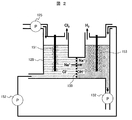
- the outline of the electrolytic cell 128 used in this embodiment will be described with reference to FIG.
- the electrolytic cell 128 has a structure in which a positive electrode side cell and a negative electrode side cell are partitioned by a semipermeable membrane 150, and the potential difference between both electrodes is controlled to about 3-5V, for example.
- the concentrated waste water from the MED device 116 is supplied to the positive electrode side cell of the electrolytic cell 128.
- Sodium ions and hydroxide ions generated in the electrolytic bath 128 are discharged from the electrolytic bath as caustic soda water and supplied to the CO 2 absorber 133 by the liquid feed pump 132.
- the accompanying water may contain sodium bicarbonate or sodium carbonate, that is, carbonate ions or bicarbonate ions.
- carbonated ions or bicarbonate ions are contained in the concentrated wastewater of the accompanying water, these ions are not affected and the chlorine ions are oxidized unless the potential difference is set to a value that is much larger than the above value.
- concentration wastewater of the accompanying water contains few chloride ions and contains a lot of carbonate ions and bicarbonate ions, the chloride ions are removed in the positive electrode cell by electrolysis, and carbonate ions and bicarbonate ions (sodium bicarbonate) And sodium carbonate) will remain.
- wastewater electrolyticzed water
- predetermined treatment for example, the presence or absence of chlorine ions is confirmed, and if chlorine ions are not detected, heating treatment is performed. Etc.
- the liquid is fed to the negative electrode side cell of the electrolytic cell 128 by the liquid feed pump 152.
- sodium hydrogencarbonate and sodium carbonate can be obtained with high purity.
- the water level on the negative electrode side can be maintained without supplying electrolytic water to the negative electrode side from the outside.
- the chlorine gas discharged from the upper part of the positive electrode side cell of the electrolytic cell 128 is sent to a chlorine purification / liquefaction system. Since chlorine gas contains moisture and is highly corrosive, the air supply pipe is preferably made of a corrosion-resistant material such as a glass lining material.
- the chlorine gas containing moisture discharged from the electrolytic bath 128 is cooled to about 0 to 15 ° C. by the heat exchange type cooler 136, so that most of the moisture is condensed.
- the heat exchange type cooler 136 By passing through the gas-liquid separator 137 in this state, the condensate is removed.
- the chlorine gas that has passed through the gas-liquid separator 137 is sent to the dryer 138.
- the dryer 138 is, for example, an aeration tank for concentrated sulfuric acid, whereby a trace amount of water remaining in the chlorine gas is removed. Concentrated sulfuric acid is supplied to the dryer 138 from the concentrated sulfuric acid tank 139 by the liquid feed pump 140.
- the sulfuric acid that has absorbed the moisture of the chlorine gas is sent to the sulfuric acid concentration tank 143 by the liquid feed pump 141.
- the sulfuric acid concentration tank 143 is a heating device, for example, and regenerates concentrated sulfuric acid by heating and evaporating moisture.
- the regenerated concentrated sulfuric acid is collected in the concentrated sulfuric acid tank 139 by the liquid feed pump 142.
- the dry chlorine gas discharged from the dryer 138 is sent to the chlorine gas liquefier 144 and liquefied.
- the chlorine gas liquefying apparatus 144 is constituted by, for example, a cooling apparatus, a compressor, or a combination of both. In the case of a cooling device, the chlorine gas can be liquefied independently by cooling below the liquefaction temperature of chlorine ( ⁇ 35 ° C.).
- the liquefied chlorine discharged from the chlorine gas liquefier 144 is sent to the liquefied chlorine tank 146 by the liquid feed pump 145 and stored.
- Liquefied chlorine is used as a raw material for useful products such as hydrochloric acid, sodium hypochlorite, calcium hypochlorite, and vinyl chloride monomers.
- the hydrogen gas generated in the negative electrode side cell of the electrolytic cell is a flammable gas, so it is necessary to ensure sufficient exhaust and safety so that it does not remain in the electrolytic cell.
- the fuel is sent to the combustor of the gas turbine 121 and used as part of the fuel. As a result, there is an advantage that the fuel supplied to the gas turbine can be reduced.
- the power / supply system includes a gas turbine 121, a generator 122 driven by the gas turbine, an exhaust heat recovery boiler 123 that generates steam using the exhaust gas of the gas turbine, and steam from the exhaust heat recovery boiler. It is comprised from the steam turbine 147 driven using, and the generator 148 driven by a steam turbine.
- the combustor of the gas turbine 121 is supplied with a part of the production gas purified by the gas processing device 102 as fuel. Further, hydrogen gas generated in the electrolytic cell 128 is also supplied to the combustor as fuel and is effectively used. In the example of FIG. 1, hydrogen gas generated in a part of the production gas or in the electrolytic cell is used as the gas turbine fuel, but various liquid fuels and gas fuels supplied from outside the system may be used. Further, the generator 122 may be replaced with the gas turbine 121 and another internal combustion engine such as a gas engine or a diesel engine may be used.
- the combustion exhaust gas generated by the combustor of the gas turbine 121 is a high temperature of 1000 to 1600 ° C.
- the exhaust heat recovery boiler 123 introduces this combustion exhaust gas and heats the boiler feed water sent from the liquid feed pump 124 to generate steam.
- This steam is supplied to the steam turbine 147 as a working medium, and rotationally drives the steam turbine.
- the power generation by the steam turbine 147 is effective because there is little demand for steam in the system, and when an excessive amount of steam is produced by the exhaust heat recovery boiler 123, the waste heat is effectively used.
- the above-described MED apparatus 116 is not affected by the presence or absence of the steam turbine 147 because it does not hinder the operation even with steam having a relatively low pressure.
- Electric energy generated by the generators 122 and 148 is supplied to various pumps such as the feed water pump 103 and the high-pressure water pump 110, and the electrolytic cell 128 and the like.
- the electrolytic cell 128 is supplied with electric energy after being converted into a DC voltage suitable for electrolysis by the transformer / converter 127.
- the steam turbine 147 and the generator 148 may not be installed as necessary.
- the steam from the exhaust heat recovery boiler is directly supplied to the MED device 116 via the ejectors 119 and 120.
- Exhaust gas discharged from the exhaust heat recovery boiler 123 is used for carbonation of caustic soda water from the electrolytic cell 128 in a CO2 absorber 133 described later.
- the temperature of the exhaust gas discharged from the exhaust heat recovery boiler 123 is reduced to about 150 to 200 ° C.
- exhaust gas from the exhaust heat recovery boiler 123 is sent to the scrubber 129.
- the scrubber 129 removes SOx and NOx components contained in the exhaust gas, and sends the exhaust gas containing the SOx and NOx components to the CO2 absorption device 133, so that the soda and sodium carbonate generated in the CO2 absorption device 133 are sent to the scrubber 129. This reduces the contamination of impurities.
- a part of the electrolyzed water (caustic soda water) generated in the negative electrode side cell of the electrolytic cell 128 is sent to the scrubber 129 by the liquid feed pump 131.
- Caustic soda water is sprayed into the scrubber 129 into which the exhaust gas from the exhaust heat recovery boiler 123 is introduced, and gas-liquid contact between the caustic soda water and the exhaust gas (aeration of the exhaust gas to the caustic soda water) is performed.
- Alkaline components such as caustic soda in the electrolyzed water react with SOx and NOx components contained in the exhaust gas, and these are removed from the exhaust gas.
- the alkali content in the electrolyzed water reacts preferentially with SOx and NOx components, which are strong acid components in the combustion exhaust gas, over CO 2 which is a weak acid component, and salt is generated.
- the produced salt is evaporated and dried by heating with contact with the exhaust gas to become a solid, and is sent to the powder separator 130 along the flow of the exhaust gas.
- the exhaust gas is sent to the CO2 absorber 133.
- the separated and removed salt is discharged from the powder separator 130 as a mixed salt as necessary.
- the powder separator 130 is a bag filter or a cyclone.
- the scrubber 129 and the powder separator 130 may be omitted because there are fewer impurities in the final product when the exhaust gas contains a small amount of SOx or NOx strong acid component. Further, spraying into the scrubber 129 may use liquid such as amine supplied from the outside of the system, or water, instead of alkaline electrolyzed water from the electrolytic cell 128.
- the CO2 absorber 133 of the electrolysis / volume reduction system will be described.
- the caustic soda water from the electrolysis tank 128 is aerated to the exhaust gas derived from the combustion exhaust gas of the gas turbine, the carbon dioxide contained in the exhaust gas is absorbed into the caustic soda water, and reacted with the caustic soda.
- Sodium (sodium bicarbonate, NaHCO3) or sodium carbonate (Na2CO3) is produced, and carbon dioxide contained in the exhaust gas is thereby immobilized.
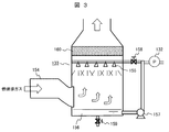
- the outline of the CO2 absorber 133 used in this embodiment will be described with reference to FIG.
- the exhaust gas sent from the powder separator 130 is supplied from the supply port 154 to the inside.
- Caustic soda water (alkaline electrolyzed water) sent from the electrolytic cell 128 via the liquid feed pump 132 is sprayed from the spray nozzle 155 to the CO2 absorber 133 into which the exhaust gas has been introduced.
- the alkaline content of the electrolyzed water reacts with CO 2 contained in the exhaust gas, so that a salt is generated and removed from the exhaust gas.
- the production ratio of sodium bicarbonate and sodium carbonate depends on the carbon dioxide concentration in the gas. That is, in the case of caustic soda, salt produced by the reaction with CO 2 varies by CO 2 concentration in the exhaust gas, CO 2 concentration of 5% larger than the generation of the sodium bicarbonate is dominant, the very less than 5% Production of sodium carbonate becomes dominant. In the vicinity of 5%, it is a mixture of both. Therefore, the target final product (such as baking soda or sodium carbonate) can be obtained by changing the CO 2 concentration in the exhaust gas.
- the concentration of carbon dioxide contained in the combustion exhaust gas of the gas turbine 121 is small (about 2%), when increasing the carbon dioxide concentration of the exhaust gas supplied to the CO2 absorber 133, for example, CO 2 gas is added to the combustion exhaust gas.
- a method of adding can be considered.
- the accompanying gas containing CO 2 gas which is separated and removed from the production gas when the natural gas mined from the gas field 101 is purified by the gas processing device 102, is used as the exhaust gas from the exhaust heat recovery boiler 123.
- the combined exhaust gas is supplied to the scrubber 129.
- the carbon dioxide concentration can be adjusted by separating and collecting an appropriate amount of CO 2 gas from the accompanying gas by the gas processing apparatus 102 and mixing it with the exhaust gas.
- mixing accompanying gas with waste gas is useful also from a viewpoint of adjusting the temperature of waste gas (for example, reducing).
- an engine power generator such as a gas engine or a diesel engine is used instead of the gas turbine 121, and the exhaust gas (CO 2 concentration is about 10%).
- the characteristic of changing the CO 2 concentration in the gas to obtain the desired final product is not essential for the gas turbine exhaust gas.
- a gas or the like may be used to change the CO 2 concentration in the gas.
- the salt produced by the CO2 absorber 133 is evaporated and dried by heating with contact with the exhaust gas and becomes solid.
- the solid salt content is sent to the powder separator 134 after a trace amount of residual moisture is removed by passing through the mist separator 160 on the exhaust gas flow.
- the temperature of the exhaust gas is reduced by heat exchange with the alkaline liquid (caustic soda water) sprayed from the spray nozzle 155, and the concentration of carbon dioxide is also reduced.
- the powder separator 134 solid salt is separated and removed from the exhaust gas, and then sent to the sodium carbonate tank 135 as a final product.
- a bag filter, a ceramic filter, a cyclone, or the like is used for the powder separator 134.
- the liquid remaining without being evaporated and dried, or the liquid removed by the mist separator 160 flows down into the pool 156 and accumulates. This is returned to the spray nozzle 155 via the valve 158 by the pump 157 and sprayed again.
- the valve 159 is opened and discharged. From the powder separator 134, exhaust gas in a state where the temperature is lowered and the carbon dioxide concentration is reduced is discharged out of the system.
- the water in the concentrated waste liquid derived from the accompanying water is evaporated and removed by effectively using the thermal energy of the exhaust gas, and the volume of the waste water can be significantly reduced.
- the soda content generated from sodium chloride contained in the condensate-derived concentrated waste liquid is combined with the carbon dioxide of the exhaust gas and fixed, so that the waste can be converted into a valuable material that can be used industrially. It can also help prevent global warming.
- the salt effluent into an aqueous solution of caustic soda, the amount of dissolved and absorbed carbon dioxide is increased compared with the aqueous solution of sodium chloride, which helps to reduce the discharge amount of carbon dioxide.
- the method of aeration of caustic soda water to exhaust gas includes a method of directly aeration in an electrolytic cell, a method of aeration of caustic soda water discharged from the electrolytic cell, and electrolysis of exhaust gas. There is a method of spraying caustic soda discharged from the tank.
- the temperature of the reaction solution increases due to the heat of electrolysis and exhaust gas, so the solubility of NaHCO3 and Na2CO3 increases, so sodium bicarbonate and sodium carbonate are added. There is an advantage that it can be recovered as a solution.
- the temperature is preferably about 50 to 70 ° C. in order to reduce the evaporation of moisture from the reaction solution from the viewpoint of reducing the moisture contained in the chlorine gas.
- the temperature of a certain exhaust gas when aerated with an alkaline solution, it is necessary to lower the temperature of a certain exhaust gas to a temperature at which the alkaline solution does not boil, usually about 150 to 200 ° C. This is because when exhaust gas is directly introduced, it dries quickly and solids may accumulate in the system. Further, it is desirable that the liquid is formed so as to be easily transported until the final product state (drying / solidification). From this viewpoint, for example, the temperature of the exhaust gas is lowered to about 80 to 100 ° C. From the viewpoint of effectively using the thermal energy of the exhaust gas, for example, the water in the carbonated solution is removed by evaporation with the exhaust gas exhaust heat to dry NaHCO3 and Na2CO3.
- the final product can be recovered as a solid using the heat of the exhaust gas.
- not only free water but also water of crystallization of NaHCO3 and Na2CO3 can be devolatilized.
- Specific methods for recovering the thermal energy of the exhaust gas include, for example, a method of spraying a solution after absorbing carbon dioxide gas into the exhaust gas and evaporating and drying, a method of performing through a heat exchanger, and the like.
- Na2CO3 which is a glass raw material as a final product, it is desirable that crystallization water is removed from the viewpoint of safety in a high-temperature process during glass production.
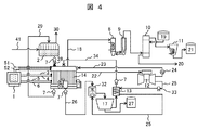
- FIG. 4 shows a system configuration 1 of the salt drainage processing apparatus.
- the MED (evaporation concentration device) 2 is installed as the salt drainage concentration device.
- the RO membrane system may be combined, or the MED (evaporation concentration device) 2 may be combined.
- an RO membrane system may be used.
- the gas turbine 12 is installed as a power / heat supply system, as described above, an exhaust heat recovery boiler and a steam turbine may also be installed.
- salt drainage 41 is supplied to MED (evaporation concentration device) 2, where it is concentrated and purified, and separated into clean water 30 and high-concentration salt drainage 28.
- MED evaporation concentration device
- a filter for removing calcium salts and the like deposited by concentration in the MED (evaporation concentration device) 2 is installed between the MED (evaporation concentration device) 2 and the electrolytic cell 14. desirable.
- the separated clean water 30 can also be supplied as makeup water that maintains the water level on the negative electrode side of the electrolytic cell.
- the high-concentration salt drainage 28 is supplied to the electrolytic cell 14 via the pump 7.
- the electric power for operating the MED (evaporation concentrator) 2 is electric energy 23 supplied from the generator 24 driven by the gas turbine 12.
- the number of the gas turbines 12 and the generators 24 may be increased to two or more as necessary when the power is insufficient. Moreover, by providing a plurality of gas turbines in this way, it can be used as a backup in case of failure.
- the high-concentration salt drainage 28 from the MED (evaporation concentration device) 2 is supplied to the positive electrode chamber of the electrolytic cell 14.
- a water level meter (+) 3 and a water level meter (-) 4 for measuring the water level, a salt concentration meter (+) 5 and a salt concentration meter (-) 6 for measuring the salt concentration are installed in the positive electrode chamber and the negative electrode chamber, respectively.
- the measured values measured by the water level meter (+) 3 and the water level meter ( ⁇ ) 4, the salt concentration meter (+) 5 and the salt concentration meter ( ⁇ ) 6 are input to the arithmetic unit 1. Yes.
- an ammeter 51 for measuring the current of the positive electrode and the negative electrode in the positive electrode chamber and the negative electrode chamber, and a voltmeter 52 for measuring the voltage are installed, and the current and voltage measured by the ammeter 51 and the voltmeter 52 are calculated by an arithmetic unit. 1, and the amount of power applied for electrolysis is controlled based on these measured values.
- the high-concentration salt drainage 28 in the positive electrode chamber is electrolyzed by the current flowing from the electrodes inserted in the positive electrode chamber and the negative electrode chamber, and converted into the high-concentration salt water 29 and the sodium hydroxide aqueous solution 26.
- the chlorine gas 18 generated in the positive electrode chamber during electrolysis in the electrolytic cell 14 is supplied to the cooler 8, cooled by the cooler 8, and then separated and washed into water vapor and salts by the mist separator 9. Then, after drying with the drying tower 10 to which the concentrated sulfuric acid 19 is supplied, it is cooled and pressurized by the cooler 11 and stored as liquid chlorine 21 in the tank. Concentrated sulfuric acid used in the drying tower 10 is discharged as waste sulfuric acid 20, and is subjected to necessary treatment and reused. Hydrogen generated in the negative electrode chamber during electrolysis in the electrolytic cell 14 is supplied to the gas turbine 12 as fuel.
- the high-concentration salt water 29 discharged from the positive electrode chamber of the electrolytic cell 14 is supplied again to the MED (evaporation concentration device) 2 via the pump 7 and concentrated together with the salt drainage 41.
- the sodium hydroxide aqueous solution 26 discharged from the negative electrode chamber of the electrolytic cell 14 is supplied by a pump 7 to a carbonation tank 32 (CO2 absorber) that is a reaction tank, and sprayed in the carbonation tank 32 to be fine. Are converted into small droplets and the surface area is increased.
- the carbon dioxide tank 32 in such a state is supplied with the exhaust gas 25 containing carbon dioxide from the gas turbine 12 through the heat exchanger 13 by the blower 33, and the sodium hydroxide aqueous solution 26 and the exhaust gas 25 containing carbon dioxide are brought into contact with each other. .
- the sodium hydroxide aqueous solution 26 and the carbon dioxide in the exhaust gas 25 react to form an aqueous solution containing sodium bicarbonate or sodium bicarbonate and sodium carbonate.
- the aqueous solution containing sodium hydrogen carbonate obtained in the carbonation tank 32 is supplied to a centrifugal separation mechanism 17 that is a recovery device, and sodium hydrogen carbonate is recovered in the centrifugal separation mechanism 17 and stored in the tank as sodium hydrogen carbonate 27.
- sodium hydrogen carbonate in the aqueous solution is precipitated using the low saturated solubility of sodium hydrogen carbonate, and the sodium hydrogen carbonate precipitated by the centrifugal separation mechanism 17 is separated from the aqueous solution.
- the sodium hydrogen carbonate aqueous solution generated in the carbonation tank 32 is heated at 150 to 200 ° C. by exhaust heat of exhaust gas, etc., so that dehydration and decarboxylation reactions occur, and it is converted into sodium carbonate solid. good.
- the temperature of the gas turbine exhaust gas is high.
- the exhaust gas is used for carbonation of caustic soda, it is desirable to cool the gas turbine exhaust gas before supplying it to the carbonation tank 32. Therefore, the exhaust gas is used for evaporation drying of an aqueous sodium hydrogen carbonate solution to lower the temperature of the exhaust gas. It is desirable to supply the carbonation tank 32 after that.
- the carbonate remains as an aqueous solution in the carbonation tank 32.
- the carbonate is evaporated and dried by the heat of exhaust gas in the carbonation tank 32. May be.
- the sodium carbonate aqueous solution and / or the sodium hydrogen carbonate solution 34 that has not been collected by the centrifugal separation mechanism 17 is heated by the heat exchanger 13 and supplied to the negative electrode chamber of the electrolytic cell 14 via the pump 7.
- the temperature of the aqueous solution in the electrolytic cell 14 is controlled to about 60 ° C., for example, the aqueous solution is heated to about 60 ° C. by the heat exchanger 13.
- the water level tends to decrease due to electrolysis of water, but the water level is maintained by supplying electrolyzed water (sodium carbonate aqueous solution and / or sodium hydrogen carbonate solution 34). Further, since the supplied water is not pure water but electrolyzed water, electrolysis in the electrolytic cell is efficiently performed.
- the salt wastewater is converted into sodium hydroxide by electrolysis, and the sodium hydroxide and carbon dioxide are reacted to generate sodium bicarbonate (sodium bicarbonate) and / or sodium carbonate. Can be increased.
- the cost is low, but also the effect that sodium chloride can be converted into a substance that can be effectively used with a low environmental load with high yield and high efficiency can be obtained.
- salt wastewater treatment it becomes possible to preferentially produce a more valuable salt, and to minimize the salt concentration in the salt wastewater.
- the temperature of the waste water can also be lowered, and the impact on the environment can be reduced. .
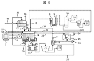
- FIG. 5 shows a system configuration 2 of the salt drainage treatment apparatus.
- the carbonation tank 32 in the system configuration example 1 shown in FIG. 4 is eliminated, and instead, the CO 2 blowing portion 16 of the exhaust gas 25 is connected to the negative electrode side of the electrolytic cell 14, The exhaust gas 25 is directly introduced, and sodium hydroxide generated by electrolysis is converted into sodium hydrogen carbonate or sodium carbonate. That is, electrolysis and carbonation are performed in the same electrolytic cell. Thereby, the mechanism which makes exhaust gas contact the waste_water
- the sodium hydrogen carbonate from the electrolytic cell 14 or an aqueous solution containing sodium carbonate is supplied to the cooling precipitation tank 15.
- the aqueous solution containing sodium hydrogen carbonate or the like is cooled in the cooling precipitation tank 15 (for example, about 5 ° C.), so that sodium hydrogen carbonate having a low saturation solubility is precipitated.
- the sodium hydrogen carbonate crystals are recovered by a centrifugal separation mechanism 17 that is a recovery device and stored in a tank as sodium hydrogen carbonate 27. Others are the same as the system configuration shown in FIG. In FIG. 5, it is actually desirable to install the centrifugal separation mechanism 17 directly below the cooling precipitation tank 15.
- FIG. 6 shows a system configuration 3 of the salt drainage treatment apparatus.
- This configuration example is the same as the system configuration example 2 shown in FIG. 5 except that the CO 2 blowing portion 16 of the exhaust gas 25 is connected to the cooling precipitation tank 15 in place of the negative electrode side of the electrolytic cell 14 and the exhaust gas is supplied to the cooling precipitation tank 15. is doing.
- a sodium hydroxide aqueous solution 26 discharged from the negative electrode chamber of the electrolytic cell 14 is supplied to the cooling precipitation tank 15, and exhaust gas is supplied from the CO 2 blowing section 16.
- the sodium hydroxide aqueous solution 26 supplied from the electrolytic cell 14 reacts with carbon dioxide in the exhaust gas 25 introduced from the CO 2 blowing unit 16 to form a sodium hydrogen carbonate aqueous solution, which is cooled in the cooling precipitation tank 15. This precipitates as crystals of sodium bicarbonate.
- the sodium hydrogen carbonate crystals are separated from the mixed aqueous solution of sodium carbonate and sodium hydrogen carbonate by the centrifugal separation mechanism 17 serving as a recovery device, and stored in the tank as sodium hydrogen carbonate 27.
- the drainage on the positive electrode side after electrolysis is also thrown into the negative electrode side.
- This method is effective when the concentration of sodium carbonate and sodium hydrogen carbonate in the salt effluent is higher than the sodium chloride concentration.
- the carbonate ions are not affected, and the chlorine ions are oxidized at the positive electrode.
- most of the sodium chloride is converted to sodium hydroxide.
- the sodium ions move to the low concentration electrode side. Therefore, when the sodium carbonate concentration and sodium hydrogen carbonate concentration on the positive electrode side are higher than the sodium chloride concentration, the sodium ion concentration on the positive electrode side can exceed the sodium ion concentration on the negative electrode side even when the total amount of sodium chloride is electrolyzed. .
- the positive electrode side can be made into sodium carbonate and sodium hydrogen carbonate, and the positive electrode side waste water after the electrolysis can be thrown into the negative electrode side.
- a water level tends to fall in the negative electrode chamber by electrolysis of water, a water level is maintained by supplying positive electrode side waste_water
- a chlorine ion concentration meter (+) 31 that measures the chlorine ion concentration in the positive electrode chamber of the electrolytic cell 14 is provided, and the measured chlorine ion concentration data in the positive electrode chamber is input to the arithmetic unit 1. It has become.
- hypochlorous acid is produced when the chlorine ions are introduced to the negative electrode side. Therefore, for example, electrolysis is performed so that the chlorine ions have a detection limit value.
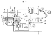
- FIG. 7 shows a system configuration 4 of the salt drainage treatment apparatus.
- This configuration example is obtained by adding a system in which waste water on the positive electrode side after electrolysis is also input to the negative electrode side as in the system configuration example 3 shown in FIG. 6 to the system configuration example 2 shown in FIG. Others are the same as the system configuration shown in FIG. 4 and FIG. ⁇ System configuration example 5>
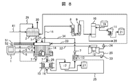
- FIG. 8 shows a system configuration 5 of the salt drainage treatment apparatus. This configuration example is obtained by omitting the system for supplying the positive-side drainage after electrolysis to the negative-electrode side in the system configuration example 3 shown in FIG. Others are the same as the system configuration shown in FIG. 4 and FIG.
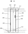
- FIG. 10 is a top view of the electrolytic cell shown in FIG.
- 200 is an electrolysis cell constituting an electrolytic cell
- 201 is a positive electrode chamber
- 202 is a negative electrode chamber
- 203 is high-concentration salt water filled in the positive electrode chamber 201
- 204 is negative electrolyzed water filled in the negative electrode chamber 202.
- 205 is a positive electrode
- 206 is a negative electrode
- 207 is a temperature sensor of the positive electrode chamber 201
- 207 ' is a temperature sensor of the negative electrode chamber 202
- 208 is a salt concentration sensor of the positive electrode chamber 201
- 208' is a salt concentration sensor of the negative electrode chamber 202
- 209 Is chlorine gas
- 210 is a chlorine gas recovery port
- 211 is a hydrogen gas discharge port
- 212 is a negative electrode electrolyzed water inlet
- 213 is a high-concentration salt water inlet
- 214 is hydrogen gas
- 215 is a negative electrode electrolyzed water drain.
- the positive electrode chamber 201 and the negative electrode chamber 202 are installed adjacent to each other only through the ion exchange membrane 221, and the positive electrode 205 and the negative electrode 206 are adjacent to the ion exchange membrane 221 in the positive electrode chamber 201 and the negative electrode chamber 202, respectively. In addition, it is laid in parallel with the ion exchange membrane 221.
- the positive electrode 205 and the negative electrode 206 are provided with a positive electrode terminal 219 and a negative electrode terminal 220, respectively.
- the positive electrode 205 and the negative electrode 206 are preferably made of a plate made of copper, platinum, gold, iridium oxide, or the like, and these may have a mesh shape installed on a current collector. Further, the positive electrode 205 and the negative electrode 206 are preferably arranged as close to the ion exchange membrane 221 as possible in order to minimize loss due to resistance during electrolysis.
- ion exchange membrane 221 a semi-permeable membrane that selectively permeates cations such as sodium is used. This membrane allows sodium ions to move from the positive electrode to the negative electrode, but chloride ions and hydroxide ions cannot pass through this membrane, so chlorine is accumulated in the positive electrode chamber and sodium hydroxide is accumulated in the negative electrode chamber. The If this ion exchange membrane 221 is not provided, it is not preferable because chloride ions, hydroxide ions, and sodium ions generated at the positive electrode react to generate sodium hypochlorite and the like.
- the positive electrode chamber 201 is provided with an introduction port 213 and a discharge port 216 for introducing the high-concentration salt water 203, and the high-concentration salt water 203 is input and drained.
- the negative electrode chamber 202 is provided with an inlet 212 and a discharge port 215 for introducing the negative electrode electrolyzed water 204, and the negative electrode electrolyzed water 204 is input and discharged.
- the negative electrode electrolyzed water 204 is introduced in order to perform electrolysis with low resistance, and is salt water containing a large amount of sodium ions and the like.
- the positive electrode chamber 201 is provided with a recovery port 210 for recovering chlorine gas 209 generated by electrolysis
- the negative electrode chamber 202 is provided with a recovery port 211 for recovering hydrogen gas 214 generated by electrolysis. Yes.
- the positive electrode chamber 201 and the negative electrode chamber 202 are provided with temperature sensors 207 and 207 ′, salt concentration sensors 208 and 208 ′, and water level meters 217 and 218, respectively.
- the temperature, salt concentration, and water level measured by these are transferred as data to the arithmetic device 1 shown in the system configuration examples 1 to 5.
- the electrolytic cell 14 configured in this manner, when an electric field is generated between the positive electrode 205 and the negative electrode 206, a current is generated across the ion exchange membrane 221, and sodium ions flow from the positive electrode 205 side to the negative electrode 206 side.
- the electrochemical reaction of the above-described formulas (1) and (2) occurs in the electrode, and chlorine is generated on the positive electrode 205 side and hydrogen is generated on the negative electrode 206 side.
- sodium hydroxide is formed and the negative electrode It is accumulated in the negative electrode electrolyzed water 204 in the chamber 202.
- the electrolytic cell 200 is preferably provided with a small volume with respect to the electrode in order to efficiently electrolyze the high-concentration salt water 203 that has passed therethrough.
- a plurality of the electrolytic cells 200 are installed in parallel. Thus, it is preferable to perform an electric field.
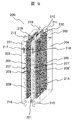
- FIG. 11 shows another example of the electrolytic cell.
- the exhaust gas 25 containing carbon dioxide from the gas turbine 12 is aerated in the negative electrode chamber 202, and sodium hydroxide and carbon dioxide generated in the negative electrode electrolyzed water 204 in the negative electrode chamber 202 are discharged into the negative electrode chamber 202.
- It is an electrolytic cell for making it react in the inside and obtaining sodium hydrogencarbonate or sodium carbonate.
- 222 is a carbon dioxide inlet
- 223 is a carbon dioxide outlet.
- FIG. 12 shows still another example of the electrolytic cell.
- the example shown in the figure shows an electrolytic cell in which a plurality of electrolytic cells 200 shown in FIGS. 9 and 10 are arranged in parallel.
- 200 is an electrolysis cell
- 224 is a recovery tube for recovering hydrogen generated in the negative electrode chamber of each electrolysis cell
- 225 is a recovery tube for recovering chlorine generated in the positive electrode chamber of each electrolysis cell 200
- 226 is negative electrode electrolysis
- An introduction pipe for water 204, 227 is an introduction pipe for high-concentration salt drainage to be introduced into the positive electrode chamber, 228 is a discharge pipe for negative electrode electrolyzed water 204, and 229 is an exhaust pipe for high-concentration salt drainage in the positive electrode compartment.
- FIG. 12 shows an example in which the electrolysis cells 200 shown in FIG. 9 are connected in parallel, but the number of cells in parallel is not particularly limited to this, and a large capacity electrolyzer such as 80 to 100 cells is used. It is also possible to form.
- the hydrogen recovery pipe 224 is a pipe that connects the recovery port 211 provided in the negative electrode chamber of each electrolysis cell 200 in parallel, and is supplied again as the fuel of the gas turbine 12, and if necessary. It is exhausted by the power of a blower (not shown).
- the chlorine recovery pipe 225 is a pipe connecting the chlorine gas recovery port 210 provided in the positive electrode chamber of each electrolysis cell 200 in parallel, and the coolers 8 and 11, the mist separator 9, the drying tower of FIGS. 4 to 8. 10 is introduced into a chlorination section composed of 10 to form liquid chlorine 21 and finally carried out as a valuable resource. If necessary, exhaust is performed by power from a blower (not shown).
- these liquids are supplied to the electrolysis cell 200 by power of a liquid feed pump or the like separately provided through an introduction pipe 226 of negative electrode electrolyzed water 204 introduced into the negative electrode and an introduction pipe 227 of high-concentration salt drain introduced into the positive electrode.
- the negative electrode electrolyzed water 204 is fed to a sodium carbonate or sodium hydrogen carbonate recovery unit by the power of a liquid feed pump or the like separately provided through the discharge pipe 228 of the negative electrode electrolyzed water 204
- the high-concentration salt water 203 is a high concentration of the positive electrode It is introduced into the MED (evaporation concentration apparatus) 2 or the negative electrode chamber 202 through the salt drain discharge pipe 229.
- FIG. 13 shows still another example of the electrolytic cell.
- the example shown in the figure shows an electrolytic cell in which a plurality of electrolytic cells 200 having a mechanism for aeration of carbon dioxide shown in FIG. 11 are arranged in parallel.
- reference numeral 230 denotes an introduction pipe for the exhaust gas 25 containing carbon dioxide.
- the introduction pipe 230 is a pipe for connecting the carbon dioxide introduction ports 222 of the electrolysis cells 200 in parallel, and is introduced using power such as a blower (not shown) as necessary.
- Concentrated high-concentration salt drainage is obtained by passing the accompanying water through the RO membrane system and the MED system.
- concentrations of cation and anion species in this high-concentration salt effluent are as follows. Cation species Na 59,000mg / L Other cations 700mg / L or less anionic species Cl 77,200mg / L CO 3 181mg / L HCO 3 23,000mg / L Other anions 700 mg / L or less and COD is 300 mg / L or less.
- sodium chloride other than water (128,000mg / L: 12.8g (0.22mol) in 1L), sodium carbonate (247mg / L: 0.247g (0.0032mol) in 1L),
- the main substance is sodium bicarbonate (32,000 mg / L: 32 g (0.38 mol) in 1 L). That is, the accompanying water is a salt drainage with a small amount of sodium chloride and a large amount of carbonate.
- This salt drainage is put into the positive electrode chamber of the electrolysis cell shown in FIG. 9, and 60,000 mg / L sodium carbonate aqueous solution is put into the negative electrode chamber for electrolysis.
- the 60,000 mg / L sodium carbonate aqueous solution has an electrolyzed water concentration after passing through the centrifugal separation mechanism shown in FIG.
- the internal dimensions of the positive electrode side and the negative electrode side of the electrolysis cell are both 1 m ⁇ 1 m ⁇ 0.01 m, and the volume is 10 L.
- the water temperature at the time of charging both was 70 ° C.
- electrolysis is performed with a voltage of 3 V and a current of 60 amperes. Chlorine gas bubbles are generated from the positive electrode, and electrolysis proceeds.
- sodium ions in the positive electrode chamber move to the negative electrode chamber and the sodium ion concentration in the positive electrode chamber decreases, but the sodium ion concentration adjustment mechanism reduces the sodium concentration difference between the positive electrode chamber and the negative electrode chamber to 3% or more. Therefore, this state is set as a steady state, and high-concentration salt drainage is introduced to achieve a stable operation state.
- 90,000 mg / L sodium chloride high-concentration salt water is discharged from the positive electrode chamber through the discharge port, and is again input to the evaporation concentrator. According to this, it is shown that an amount of sodium corresponding to 38,000 mg / L sodium chloride moves to the negative electrode chamber.
- the sodium ion concentration in the negative electrode chamber becomes 72,000 mg / L. This is an increase of 12,000 mg / L sodium ion compared to the initial 60,000 mg / L. This indicates that 21,000 mg / L sodium hydroxide is produced in the negative electrode chamber.
- This liquid is fed to the carbonation layer 32 shown in FIG. 4 using the pump 7 and sprayed in a spray form. The exhaust gas 25 of the gas turbine 12 is blown into this, and sodium hydroxide is converted to sodium carbonate, and crystallized to be recovered as sodium hydrogen carbonate 27 as a powder.
- Concentrated high-concentration salt drainage is obtained by passing the accompanying water through the RO membrane system and the MED system.
- concentrations of cation and anion species in this high-concentration salt effluent are as follows. Cation species Na 23000mg / L Other cations 100mg / L or less anionic species Cl 7100mg / L CO 3 1500mg / L HCO 3 46000mg / L Other anions were 100 mg / L or less and COD was 100 mg / L or less.
- This salt drainage is put into the positive electrode of the electrolytic cell shown in FIG. 9, and 0.5 wt% sodium carbonate aqueous solution is put into the negative electrode side for electrolysis.
- the inner dimensions of the positive electrode side and the negative electrode side of the electrolytic cell are both 1 m ⁇ 1 m ⁇ 0.01 m, and the volume is 10 L.
- the water temperature at the time of charging both was 70 ° C.
- electrolysis is performed with a voltage of 3 V and a current of 5.9 amperes. Chlorine gas bubbles are generated from the positive electrode, and electrolysis proceeds. As the electrolysis progresses, the sodium ions on the positive electrode side move to the negative electrode side and the sodium ion concentration on the positive electrode side decreases, but after 10 hours no bubbles are generated and the Cl concentration on the positive electrode side is below the detection limit. Become. The Na concentration also decreased by 4600 mg / L, and it can be judged that the electrolysis of sodium chloride on the positive electrode side was almost completed.
- the negative electrode side is strongly basic.
- hydrogen gas bubbles are generated from the negative electrode, and generation cannot be confirmed after 10 hours.
- the aqueous solution on the negative electrode side is discharged, and the combustion exhaust gas is brought into contact with the carbonation tank. Thereafter, the aqueous solution is dried by heating at 150 to 200 ° C. to obtain a white solid (156 g).
- This solid is sodium carbonate.
- 0.5% by weight of sodium carbonate is dissolved in the aqueous solution in advance, and when 50 g of this amount is subtracted, 106 g of sodium carbonate is obtained by electrolysis and combustion exhaust gas contact.
- sodium chloride is almost lost in the aqueous solution on the positive electrode side by electrolysis, and sodium carbonate and sodium hydrogen carbonate are the main components. Therefore, this is also heated and dried at 150 to 200 ° C., so that sodium hydrogen carbonate undergoes decarboxylation and dehydration reactions, and changes to sodium carbonate after heating. Eventually sodium carbonate (425 g) is obtained.
- the aqueous solution After discharging the aqueous solution on the negative electrode side, the aqueous solution is heated and dried at 150 to 200 ° C. to obtain a white solid (156 g).
- This solid is sodium carbonate.
- 0.5% by weight of sodium carbonate is dissolved in the aqueous solution in advance, and when 50 g of this amount is subtracted, 106 g of sodium carbonate can be obtained by electrolysis and combustion exhaust gas contact.
- sodium carbonate (425 g) is obtained by heating and drying the aqueous solution on the positive electrode side.
- the salt drainage treatment method of the present invention is summarized as follows.
- (1) The first step of concentrating salt effluent by separating water from salt effluent containing sodium chloride to produce high-concentration salt effluent, and the electricity and steam necessary to implement this concentration, fossil fuel
- the second step of producing or generating with the energy generated by burning the battery and the high-concentration salt drainage are introduced into the positive electrode side of the electrolytic cell in which the positive electrode and the negative electrode are separated by a semipermeable membrane that permeates sodium ions.
- the step of contacting the salt drainage with the exhaust gas after the electrolysis is moved from the electrolytic cell to a mechanism for contacting the exhaust gas, and then dropletized and contacted with the exhaust gas (1) to (4), ( 6) The method for treating salt effluent according to any one of the above.
- the step of recovering sodium carbonate and / or sodium hydrogen carbonate the aqueous solution containing sodium carbonate and / or sodium hydrogen carbonate is recovered by heating and drying, (1) to (7) Salt drainage treatment method.
- the aqueous solution containing sodium carbonate and / or sodium bicarbonate is cooled to precipitate sodium carbonate and / or sodium bicarbonate, and this is recovered ( The method for treating salt effluent according to any one of 1) to (7).
- the aqueous solution containing sodium carbonate and / or sodium hydrogen carbonate is cooled to precipitate sodium carbonate and / or sodium hydrogen carbonate.
- the salt drainage treatment method according to any one of (1) to (7), wherein the residue liquid is returned to the negative electrode side of the electrolytic cell.
- a method for treating salt wastewater that uses hydrogen gas generated from the positive electrode of the electrolytic cell, or a mixed gas of hydrogen gas and exhaust gas in which fossil fuel is introduced into the electrode after combustion, as fuel for energy generation.
- the electrolytic cell is composed of a positive electrode chamber, a negative electrode chamber and a semipermeable membrane separating the negative electrode chamber, and the semipermeable membrane has a mechanism for passing sodium ions into the positive electrode chamber and introducing salt drainage into the negative electrode.
- Has a mechanism for introducing an aqueous solution of sodium hydroxide or sodium carbonate has a mechanism for recovering chlorine gas generated by electrolysis on the positive electrode side, and recovers hydrogen gas generated by electrolysis on the negative electrode side
- a mechanism for introducing exhaust gas generated by fossil fuel combustion into the negative electrode a mechanism for discharging the aqueous solution from the positive electrode and the negative electrode side after introduction, and a mechanism for heating and drying the aqueous solution discharged from the negative electrode
- salts waste water treatment apparatus having a mechanism for recovering the solid formed after drying.
- a salt drainage treatment apparatus that, after discharging an aqueous solution from the negative electrode after electrolysis in the electrolytic cell and contacting with carbonic acid, sprays the aqueous solution into droplets to make contact with carbonic acid.
- the salt wastewater treatment apparatus according to any one of (12) to (15), further comprising a centrifugal separation mechanism for cooling the aqueous solution discharged from the negative electrode and recovering the generated solid.
- the salt wastewater treatment apparatus according to any one of (12) to (18), which has a mechanism for feeding the aqueous solution discharged from the positive electrode to the negative electrode.
- this invention is not limited to the above-mentioned Example, Various modifications are included.
- the above-described embodiments have been described in detail for easy understanding of the present invention, and are not necessarily limited to those having all the configurations described.
- a part of the configuration of one embodiment can be replaced with the configuration of another embodiment, and the configuration of another embodiment can be added to the configuration of one embodiment.
- Neutralization tank 110 ... High pressure water pump, 111 ... RO membrane desalination device, 112 ... Chemical cleaning / wastewater treatment device, 113 ... Pressure energy recovery device, 114 ... Backwash device, 115 ... Product gas supply blower, 116 ... MED device, 118 ... Heat radiating section, 119, 120 ... Ejector, 123 ... Waste heat recovery boiler, 124, 125, 126, 131, 132, 140, 141, 142, 145 ... Liquid feeding pump, 127 ... transformer, 129 ... scrubber, 130, 134 ... powder separator, 133 ... CO 2 absorber, 135 ... soda bath, 136 ... Heat exchange type cooler, 137 ...
- Gas-liquid separator 138 ... Dryer, 139 ... Concentrated sulfuric acid tank, 143 ... Sulfuric acid concentration tank, 144 ... Chlorine gas liquefier, 146 ... Liquefied chlorine tank, 147 ... Steam turbine, DESCRIPTION OF SYMBOLS 200 ... Electrolytic cell, 201 ... Positive electrode chamber, 202 ... Negative electrode chamber, 203 ... High concentration salt water with which a positive electrode chamber is filled, 204 ... Negative electrode electrolyzed water, 205 ... Positive electrode, 206 ... Negative electrode, 207 ... Temperature sensor of positive electrode chamber, 207 '... Negative electrode chamber temperature sensor, 208 ... Positive electrode chamber salt concentration sensor, 208' ...
- Negative electrode chamber salt concentration sensor 210 ... Chlorine gas recovery port, 211 ... Hydrogen gas recovery port, 212 ... Negative electrode electrolyzed water introduction 213 ... High concentration salt water introduction port, 214 ... Hydrogen gas, 215 ... Negative electrode electrolyzed water discharge port, 216 ... Positive electrode high concentration salt water discharge port, 217 ... Positive electrode chamber water level meter, 218 ... Negative electrode chamber water level meter 219 ... Positive electrode Terminal 220, negative electrode terminal, 221 ... ion exchange membrane, 222 ... carbon dioxide inlet, 223 ... carbon dioxide outlet, 224 ... recovery tube for recovering hydrogen generated in the negative electrode chamber, 225 ... generated in the positive electrode chamber Recovery pipe for recovering chlorine, 226... Negative electrode electrolytic water introduction pipe, 227... High concentration salt drain introduction pipe introduced into the positive electrode chamber, 228... Negative electrode electrolytic water discharge pipe, 229. Waste water discharge pipe, 230 ... exhaust gas introduction pipe.
Abstract
Description
2NaCl → 2Na+- + 2Cl- → 2Na+ + Cl2+ 2e- … (1)
2H2O + 2e- → 2OH+ + H2 … (2)
この反応では、苛性ソーダ生成量と等モル量の電荷が必要となるので、大規模に継続的に実施する場合、膨大な直流電流が必要となる。 When water containing sodium chloride is electrolyzed, caustic soda, chlorine, and hydrogen are generated as in the electrolytic chemical reactions shown in the following formulas (1) and (2). That is, in this reaction, chlorine ions are oxidized at the
2NaCl → 2Na + − + 2Cl − → 2Na + + Cl 2 + 2e − (1)
2H 2 O + 2e − → 2OH + + H 2 (2)
In this reaction, an amount of electric charge equivalent to the amount of caustic soda produced is required, so that enormous direct current is required when continuously carried out on a large scale.
<システム構成例1>
図4は塩排水の処理装置のシステム構成1を示す。本構成例では、塩排水の濃縮装置として、MED(蒸発濃縮装置)2のみを設置しているが、上述したように、RO膜システムを組み合せても良いし、MED(蒸発濃縮装置)2に代えてRO膜システムを用いるようにしても良い。また、電力・熱供給システムとしてガスタービン12のみ設置しているが、上述したように排熱回収ボイラや蒸気タービンも併せて設置しても良い。 Next, several configuration examples of the salt drainage treatment apparatus of the present invention will be described with reference to FIGS.
<System configuration example 1>
FIG. 4 shows a
<システム構成例2>
図5は塩排水の処理装置のシステム構成2を示す。本構成例は、図4に示すシステム構成例1における炭酸化槽32をなくし、代わりに、排ガス25のCO2吹き込み部16を電解槽14の負極側につなぎ、電解槽14の負極室中に排ガス25を直接導入し、電気分解で生成した水酸化ナトリウムを炭酸水素ナトリウム、或いは炭酸ナトリウムに変換するようにしたものである。即ち、電解と炭酸化を同じ電解槽で行うようにしたものである。これにより電解後の排水に、排ガスを接触させる機構が不要となる。 In the present embodiment, an aqueous solution of sodium hydroxide is sprayed in the
<System configuration example 2>
FIG. 5 shows a
<システム構成例3>
図6は塩排水の処理装置のシステム構成3を示す。本構成例は、図5に示すシステム構成例2において、排ガス25のCO2吹き込み部16を、電解槽14の負極側に代えて、冷却析出槽15につなぎ、冷却析出槽15に排ガスを供給している。冷却析出槽15には、電解槽14の負極室から排出された水酸化ナトリウム水溶液26が供給され、CO2吹込み部16から排ガスが供給されている。電解槽14から供給された水酸化ナトリウム水溶液26と、CO2吹込み部16から導入された排ガス25中の二酸化炭素とが反応し、炭酸水素ナトリウム水溶液となり、これが冷却析出槽15で冷却されることにより炭酸水素ナトリウムの結晶として析出される。炭酸水素ナトリウムの結晶は、回収装置である遠心分離機構17において炭酸ナトリウムと炭酸水素ナトリウムの混合水溶液から分離され、タンクに炭酸水素ナトリウム27として貯蔵される。 Furthermore, in this system, the sodium hydrogen carbonate from the
<System configuration example 3>
FIG. 6 shows a system configuration 3 of the salt drainage treatment apparatus. This configuration example is the same as the system configuration example 2 shown in FIG. 5 except that the CO 2 blowing portion 16 of the
<システム構成例4>
図7は塩排水の処理装置のシステム構成4を示す。本構成例は、図5に示すシステム構成例2に、図6に示すシステム構成例3のように、電気分解後の正極側の排水を負極側にも投入する系統を追加したものである。その他は、図4、図5に示すシステム構成と同じであり、説明を省略する。
<システム構成例5>
図8は塩排水の処理装置のシステム構成5を示す。本構成例は、図6に示すシステム構成例3における、電気分解後の正極側の排水を負極側にも投入する系統を省略したものである。その他は、図4、図6に示すシステム構成と同じであり、説明を省略する。
<電解槽の構成例>
図9及び図10に、本発明の実施例に採用される電解槽の一例を示す。図10は、図9に示す電解槽の上面図である。これらの図において、200は電解槽を構成する電解セル、201は正極室、202は負極室、203は正極室201に充填される高濃度塩水、204は負極室202に充填される負極電解水、205は正極、206は負極、207は正極室201の温度センサ、207´は負極室202の温度センサ、208は正極室201の塩濃度センサ、208´は負極室202の塩濃度センサ、209は塩素ガス、210は塩素ガスの回収口、211は水素ガスの排出口、212は負極電解水の導入口、213は高濃度塩水の導入口、214は水素ガス、215は負極電解水の排出口、216は正極高濃度塩水の排出口、217は正極室の水位計、218は負極室の水位計、219は正極端子、220は負極端子、221はイオン交換膜である。 Others are the same as the system configuration shown in FIG. 4 and FIG.
<System configuration example 4>
FIG. 7 shows a system configuration 4 of the salt drainage treatment apparatus. This configuration example is obtained by adding a system in which waste water on the positive electrode side after electrolysis is also input to the negative electrode side as in the system configuration example 3 shown in FIG. 6 to the system configuration example 2 shown in FIG. Others are the same as the system configuration shown in FIG. 4 and FIG.
<System configuration example 5>
FIG. 8 shows a system configuration 5 of the salt drainage treatment apparatus. This configuration example is obtained by omitting the system for supplying the positive-side drainage after electrolysis to the negative-electrode side in the system configuration example 3 shown in FIG. Others are the same as the system configuration shown in FIG. 4 and FIG.
<Example of electrolytic cell configuration>
9 and 10 show an example of an electrolytic cell employed in the embodiment of the present invention. FIG. 10 is a top view of the electrolytic cell shown in FIG. In these drawings, 200 is an electrolysis cell constituting an electrolytic cell, 201 is a positive electrode chamber, 202 is a negative electrode chamber, 203 is high-concentration salt water filled in the
<適用例>
以下、ガス田から排出される随伴水の処理へ本発明の実施例の塩排水の処理装置を適用した場合について、物質収支計算、電力収支計算、熱収支計算などを実施し、本発明の実施例の効果を確認した。なお、本発明はこれらに限定されるものではない。
<適用例1>
図1、図4に示すシステムで、あるガス田Aから排出される随伴水を処理する場合について説明する。 When aeration of carbon dioxide shown in FIGS. 11 and 13 is performed in the negative electrode chamber, nitrogen, oxygen, moisture, and unreacted carbon dioxide contained in the
<Application example>
Hereinafter, the material balance calculation, the power balance calculation, the heat balance calculation, etc. are performed for the case where the salt drainage treatment apparatus of the embodiment of the present invention is applied to the treatment of the accompanying water discharged from the gas field, and the implementation of the present invention. The effect of the example was confirmed. The present invention is not limited to these.
<Application example 1>
The case where the accompanying water discharged | emitted from a certain gas field A is processed with the system shown in FIG. 1, FIG. 4 is demonstrated.
陽イオン種
Na 59,000mg/L
その他の陽イオン 700mg/L以下
陰イオン種
Cl 77,200mg/L
CO3 181mg/L
HCO3 23,000mg/L
その他の陰イオン 700mg/L以下
またCODは300mg/L以下である。 Concentrated high-concentration salt drainage is obtained by passing the accompanying water through the RO membrane system and the MED system. The concentrations of cation and anion species in this high-concentration salt effluent are as follows.
Cation species
Na 59,000mg / L
Other cations 700mg / L or less anionic species
Cl 77,200mg / L
CO 3 181mg / L
HCO 3 23,000mg / L
Other anions 700 mg / L or less and COD is 300 mg / L or less.
排ガス組成
N2:70.0%
O2:13.0%
CO2:3.4%
H2O:11.0%
Ar:0.9%
その他:11.7%
ガスタービン12から排出された直後のガス温度は330℃である。このガスは熱交換器13を介して炭酸化層32に送気されるが、熱交換器通過後の温度は180℃である。二酸化炭素濃度は0.01%以上であるので、正常な運転状況となる。このとき回収できる炭酸ナトリウムは、この電解槽に通液する高濃度排塩水の通液量が100Lのとき、5.5kgとなる。 The exhaust gas composition used in this application example is shown below.
Exhaust gas composition
N2: 70.0%
O2: 13.0%
CO2: 3.4%
H2O: 11.0%
Ar: 0.9%
Other: 11.7%
The gas temperature immediately after being discharged from the
<適用例2>
図1、図4に示すシステムで、あるガス田から排出される随伴水を処理する場合について説明する。 As shown in FIG. 12, when 86 cells were juxtaposed as shown in FIG. 12 and treated at 8,600 L, it was possible to recover 473 kg of sodium carbonate.
<Application example 2>
The case where the accompanying water discharged | emitted from a certain gas field is processed with the system shown in FIG. 1, FIG. 4 is demonstrated.
陽イオン種
Na 23000mg/L
その他の陽イオン 100mg/L以下
陰イオン種
Cl 7100mg/L
CO3 1500mg/L
HCO3 46000mg/L
その他の陰イオン 100mg/L以下
またCODは100mg/L以下であった。 Concentrated high-concentration salt drainage is obtained by passing the accompanying water through the RO membrane system and the MED system. The concentrations of cation and anion species in this high-concentration salt effluent are as follows.
Cation species
Na 23000mg / L
Other cations 100mg / L or less anionic species
Cl 7100mg / L
CO 3 1500mg / L
HCO 3 46000mg / L
Other anions were 100 mg / L or less and COD was 100 mg / L or less.
<適用例3>
図11に示す電解槽で適用例2と同様、正極に塩排水、負極に0.5重量%の炭酸ナトリウム水溶液を10L投入し、電解する。その際、負極には燃焼排ガスを導入する。10時間後、正極側のCl濃度は検出限界以下となる。Na濃度も4600mg/L低下し、塩化ナトリウムの電気分解がほぼ完了したと判断できる。 By applying the electrolytic cell in FIG. 9 to a system arranged in parallel as shown in FIG. 12, the amount of sodium carbonate obtained by drying each electrolytic cell aqueous solution after electrolysis is expected to be approximately 420 g. Obtained. Therefore, sodium carbonate can be obtained even when a plurality of electrolytic cells are arranged in parallel.
<Application example 3>
In the electrolytic cell shown in FIG. 11, as in Application Example 2, 10 L of salt drainage is added to the positive electrode and 0.5 wt% sodium carbonate aqueous solution is added to the negative electrode to conduct electrolysis. At that time, combustion exhaust gas is introduced into the negative electrode. After 10 hours, the Cl concentration on the positive electrode side falls below the detection limit. The Na concentration also decreased by 4600 mg / L, and it can be judged that the electrolysis of sodium chloride was almost completed.
(1)塩化ナトリウムを含む塩排水から水分を分離することで塩排水を濃縮し高濃度塩排水を製造する第一の工程と、この濃縮を実施するために必要な電気と蒸気を、化石燃料を燃焼することによるエネルギーで製造、または発生させる第二の工程と、高濃度塩排水を、正極と負極がナトリウムイオンを透過する半透膜で仕切られた電解槽の正極側に投入し、電気分解により高濃度塩水中に水酸化ナトリウムを生成させる第三の工程と、この水酸化ナトリウムに上記第二の工程で化石燃料を燃焼することにより生じる排ガスを接触させることにより炭酸ナトリウム及び/または炭酸水素ナトリウムを含む水溶液を得る第四の工程と、生成した炭酸ナトリウム及び/または炭酸水素ナトリウムを、炭酸ナトリウム及び/または炭酸水素ナトリウムを含む水溶液から分離回収する第五の工程と、電解槽の正極から発生する塩素を含むガス並びに負極から発生する水素を含むガスを回収する第六の工程と、を含む塩排水の処理方法。
(2)前記塩排水を濃縮する工程が最初に逆浸透膜装置、引き続き蒸発塔方式で行われる(1)に記載の塩排水の処理方法。
(3)前記塩排水を濃縮する工程が蒸発塔方式のみで行われる(1)に記載の塩排水の処理方法。
(4)前記塩排水を濃縮する工程の前に塩排水中の縣濁物質を除去する工程が行われる(1)~(3)の何れかに記載の塩排水の処理方法。
(5)前記塩排水を前記電気分解後、排ガスに接触させる工程が、電解槽の負極側に排ガスを導入する方法で行う(1)~(4)の何れかに記載の塩排水の処理方法。
(6)前記塩排水を前記電気分解後、排ガスに接触させる工程が、電解槽から排ガスを接触させる機構に移動させた後、接触させる(1)~(4)の何れかに記載の塩排水の処理方法。
(7)前記塩排水を前記電気分解後、排ガスに接触させる工程が、電解槽から排ガスを接触させる機構に移動させた後、液滴化し、排ガスと接触させる(1)~(4)、(6)の何れかに記載の塩排水の処理方法。
(8)前記炭酸ナトリウム及び/または炭酸水素ナトリウムを回収する工程において、炭酸ナトリウム及び/または炭酸水素ナトリウムを含む水溶液を加熱乾燥することで回収する(1)~(7)の何れかに記載の塩排水の処理方法。
(9)前記炭酸ナトリウム及び/または炭酸水素ナトリウムを回収する工程において、炭酸ナトリウム及び/または炭酸水素ナトリウムを含む水溶液を冷却して炭酸ナトリウム及び/または炭酸水素ナトリウムを析出させ、これを回収する(1)~(7)の何れかに記載の塩排水の処理方法。
(10)前記炭酸ナトリウム及び/または炭酸水素ナトリウムを回収する工程において、炭酸ナトリウム及び/または炭酸水素ナトリウムを含む水溶液を冷却して炭酸ナトリウム及び/または炭酸水素ナトリウムを析出させ、これを回収後、残渣の液を電解槽の負極側に戻す(1)~(7)の何れかに記載の塩排水の処理方法。
(11)前記電解槽の正極から発生する水素ガス、或いは、水素ガスと、化石燃料を燃焼後電極に導入した排ガスとの混合気体を、エネルギー発生用の燃料として利用する塩排水の処理方法。
(12)塩化ナトリウムを含む塩排水を濃縮する濃縮装置と、この濃縮を実施するために必要な電気と蒸気を化石燃料を燃焼させることにより製造、又は発生させる発電装置と、塩排水を電解する電解槽とから成り、電解槽は正極室と、負極室とそれを隔てる半透膜とから成り、該半透膜はナトリウムイオンを通し、正極室に塩排水を投入する機構を有し、負極には水酸化ナトリウム、或いは炭酸ナトリウムの水溶液を投入する機構を有し、正極側には電気分解で生じる塩素ガスを回収する機構を有し、負極側には電気分解で生じる水素ガスを回収する機構を有し、負極に化石燃料の燃焼により生じる排ガスを導入する機構を有し、導入後に正極、及び負極側から水溶液を排出する機構を有し、負極から排出された水溶液を加熱乾燥する機構を有し、乾燥後に生成する固体を回収する機構を有する塩排水処理装置。
(13)前記塩排水の濃縮装置が逆浸透膜装置、引き続き蒸発塔で行うシステムである(12)記載の塩排水処理装置。
(14)記塩排水の濃縮装置が蒸発塔で行うシステムである(12)記載の塩排水処理装置。
(15)前記塩排水の濃縮装置の前段階で塩排水中の縣濁物質を除去する工程を含む(12)~(14)の何れかに記載の塩排水処理装置。
(16)前記電解槽で電気分解後に負極側から水溶液を排出後、炭酸に接触させる塩排水処理装置。
(17)前記電解槽で電気分解後に負極から水溶液を排出後、炭酸に接触させる際、該水溶液を噴霧し液滴化とした状態で炭酸に接触させる塩排水処理装置。
(18)前記負極から排出された水溶液を冷却し、生じる固体を回収するための遠心分離機構を有する(12)~(15)の何れか記載の塩排水処理装置。
(19)前記正極から排出された水溶液を負極に投入する機構を有する(12)~(18)の何れかに記載の塩排水処理装置。
(20)負極側で生じる水素ガス、及び導入した排ガスの混合気体を発電装置の燃料として送る制御機構を有する(12)~(15)、(18)、(19)の何れかに記載の塩排水処理装置。 The salt drainage treatment method of the present invention is summarized as follows.
(1) The first step of concentrating salt effluent by separating water from salt effluent containing sodium chloride to produce high-concentration salt effluent, and the electricity and steam necessary to implement this concentration, fossil fuel The second step of producing or generating with the energy generated by burning the battery and the high-concentration salt drainage are introduced into the positive electrode side of the electrolytic cell in which the positive electrode and the negative electrode are separated by a semipermeable membrane that permeates sodium ions. A third step of generating sodium hydroxide in high-concentration salt water by decomposition, and sodium carbonate and / or carbonic acid by contacting the sodium hydroxide with exhaust gas generated by burning fossil fuel in the second step. A fourth step of obtaining an aqueous solution containing sodium hydrogen, and the generated sodium carbonate and / or sodium hydrogen carbonate, sodium carbonate and / or sodium hydrogen carbonate; And a sixth step of recovering a gas containing chlorine generated from the positive electrode of the electrolytic cell and a gas containing hydrogen generated from the negative electrode.
(2) The salt wastewater treatment method according to (1), wherein the step of concentrating the salt wastewater is first performed by a reverse osmosis membrane apparatus and then by an evaporation tower method.
(3) The salt wastewater treatment method according to (1), wherein the step of concentrating the salt wastewater is performed only by an evaporation tower method.
(4) The method for treating salt water according to any one of (1) to (3), wherein a step of removing suspended substances in the salt water is performed before the step of concentrating the salt water.
(5) The salt wastewater treatment method according to any one of (1) to (4), wherein the step of contacting the salt wastewater with the exhaust gas after the electrolysis is performed by a method of introducing the exhaust gas to the negative electrode side of the electrolytic cell. .
(6) The step of bringing the salt waste water into contact with the exhaust gas after the electrolysis is moved to the mechanism for contacting the exhaust gas from the electrolytic cell and then brought into contact with the salt waste water according to any one of (1) to (4) Processing method.
(7) The step of contacting the salt drainage with the exhaust gas after the electrolysis is moved from the electrolytic cell to a mechanism for contacting the exhaust gas, and then dropletized and contacted with the exhaust gas (1) to (4), ( 6) The method for treating salt effluent according to any one of the above.
(8) In the step of recovering sodium carbonate and / or sodium hydrogen carbonate, the aqueous solution containing sodium carbonate and / or sodium hydrogen carbonate is recovered by heating and drying, (1) to (7) Salt drainage treatment method.
(9) In the step of recovering sodium carbonate and / or sodium bicarbonate, the aqueous solution containing sodium carbonate and / or sodium bicarbonate is cooled to precipitate sodium carbonate and / or sodium bicarbonate, and this is recovered ( The method for treating salt effluent according to any one of 1) to (7).
(10) In the step of recovering sodium carbonate and / or sodium hydrogen carbonate, the aqueous solution containing sodium carbonate and / or sodium hydrogen carbonate is cooled to precipitate sodium carbonate and / or sodium hydrogen carbonate. The salt drainage treatment method according to any one of (1) to (7), wherein the residue liquid is returned to the negative electrode side of the electrolytic cell.
(11) A method for treating salt wastewater that uses hydrogen gas generated from the positive electrode of the electrolytic cell, or a mixed gas of hydrogen gas and exhaust gas in which fossil fuel is introduced into the electrode after combustion, as fuel for energy generation.
(12) Concentrating device for concentrating salt drainage containing sodium chloride, power generation device for producing or generating electricity and steam necessary for carrying out this concentration by burning fossil fuel, and electrolyzing salt drainage The electrolytic cell is composed of a positive electrode chamber, a negative electrode chamber and a semipermeable membrane separating the negative electrode chamber, and the semipermeable membrane has a mechanism for passing sodium ions into the positive electrode chamber and introducing salt drainage into the negative electrode. Has a mechanism for introducing an aqueous solution of sodium hydroxide or sodium carbonate, has a mechanism for recovering chlorine gas generated by electrolysis on the positive electrode side, and recovers hydrogen gas generated by electrolysis on the negative electrode side A mechanism for introducing exhaust gas generated by fossil fuel combustion into the negative electrode, a mechanism for discharging the aqueous solution from the positive electrode and the negative electrode side after introduction, and a mechanism for heating and drying the aqueous solution discharged from the negative electrode The And, salts waste water treatment apparatus having a mechanism for recovering the solid formed after drying.
(13) The salt drainage treatment apparatus according to (12), wherein the salt drainage concentration apparatus is a reverse osmosis membrane apparatus and a system that is subsequently performed in an evaporation tower.
(14) The salt effluent treatment apparatus according to (12), wherein the salt effluent concentration apparatus is a system performed in an evaporation tower.
(15) The salt wastewater treatment apparatus according to any one of (12) to (14), including a step of removing suspended substances in the salt drainage before the salt drainage concentration apparatus.
(16) A salt drainage treatment apparatus for contacting an aqueous solution after discharging the aqueous solution from the negative electrode side after electrolysis in the electrolytic cell.
(17) A salt drainage treatment apparatus that, after discharging an aqueous solution from the negative electrode after electrolysis in the electrolytic cell and contacting with carbonic acid, sprays the aqueous solution into droplets to make contact with carbonic acid.
(18) The salt wastewater treatment apparatus according to any one of (12) to (15), further comprising a centrifugal separation mechanism for cooling the aqueous solution discharged from the negative electrode and recovering the generated solid.
(19) The salt wastewater treatment apparatus according to any one of (12) to (18), which has a mechanism for feeding the aqueous solution discharged from the positive electrode to the negative electrode.
(20) The salt according to any one of (12) to (15), (18), and (19), having a control mechanism that sends hydrogen gas generated on the negative electrode side and a mixed gas of the introduced exhaust gas as fuel for the power generation device Wastewater treatment equipment.
Claims (15)
- 塩化ナトリウムを含む塩排水から水分を分離することで塩排水を濃縮して高濃度塩排水を製造し、高濃度塩排水を、正極と負極がナトリウムイオンを透過する半透膜で仕切られた電解槽の正極側に投入して、電気分解により高濃度塩水中に水酸化ナトリウムを生成させ、この水酸化ナトリウムに、塩排水を排出するプラント又は塩排水の処理装置を作動する電気エネルギーを得るために設置されているガスタービン発電装置又はエンジン発電装置の排ガスを接触させることにより炭酸ナトリウム及び/または炭酸水素ナトリウムを含む水溶液を得て、この水溶液から炭酸ナトリウム及び/または炭酸水素ナトリウムを分離回収することを特徴とする塩排水の処理方法。 By separating water from salt wastewater containing sodium chloride, salt wastewater is concentrated to produce high-concentration salt wastewater, and the high-concentration salt wastewater is separated by a semipermeable membrane where the positive and negative electrodes permeate sodium ions. In order to obtain electric energy for operating a plant for discharging salt effluent or a processing device for salt effluent, by introducing it into the positive electrode side of the tank and generating sodium hydroxide in high-concentration salt water by electrolysis An aqueous solution containing sodium carbonate and / or sodium hydrogen carbonate is obtained by contacting the exhaust gas of the gas turbine power generator or engine power generator installed in the plant, and sodium carbonate and / or sodium hydrogen carbonate is separated and recovered from this aqueous solution. A method for treating salt effluent.
- 請求項1において、前記高濃度塩排水を前記電解槽に投入する前に、前記塩排水の濃縮する際に生じた固体を除去することを特徴とする塩排水の処理方法。 2. The method for treating salt wastewater according to claim 1, wherein solids generated when the salt wastewater is concentrated are removed before the high-concentration salt wastewater is charged into the electrolytic cell.
- 塩化ナトリウムを含む塩排水を処理する塩排水処理装置であって、
前記塩排水から水分を分離することで塩排水を濃縮する濃縮装置と、
正極と負極がナトリウムイオンを透過する半透膜で仕切られ、前記塩排水中の塩化ナトリウムを電気分解する電解槽と、
前記濃縮装置で製造された高濃度塩排水の排出口と前記電解槽の正極側との間に設けられた高濃度塩排水の供給配管と、
塩排水を排出するプラント又は塩排水処理装置を動作させる電気エネルギーを得るために設置されているガスタービン発電装置又はエンジン発電装置の排ガスを導入して、水溶液中の塩を炭酸化する炭酸化槽と、
前記電解槽の負極側の水溶液の排出口と前記炭酸化槽との間に設けられた水溶液の供給配管と、
前記炭酸化槽で生成した炭酸化塩の回収装置とを有することを特徴とする塩排水処理装置。 A salt wastewater treatment apparatus for treating salt wastewater containing sodium chloride,
A concentrator for concentrating salt wastewater by separating water from the salt wastewater;
An electrolytic cell in which a positive electrode and a negative electrode are partitioned by a semipermeable membrane that transmits sodium ions, and electrolyzes sodium chloride in the salt drainage;
A high-concentration salt drain supply pipe provided between the discharge port of the high-concentration salt drain produced by the concentrator and the positive electrode side of the electrolytic cell;
Carbonation tank that carbonates salt in an aqueous solution by introducing exhaust gas from a gas turbine power generation device or engine power generation device installed to obtain electrical energy to operate a plant that discharges salt wastewater or a salt wastewater treatment device When,
An aqueous solution supply pipe provided between the discharge port of the aqueous solution on the negative electrode side of the electrolytic cell and the carbonation tank;
A salt drainage treatment apparatus comprising a collection device for carbonated salt generated in the carbonation tank. - 塩化ナトリウムを含む塩排水を処理する塩排水処理装置であって、
前記塩排水から水分を分離することで塩排水を濃縮する濃縮装置と、
正極と負極がナトリウムイオンを透過する半透膜で仕切られ、前記塩排水中の塩化ナトリウムを電気分解する電解槽と、
前記濃縮装置で製造された高濃度塩排水の排出口と前記電解槽の正極側との間に設けられた高濃度塩排水の供給配管と、
前記電解槽の負極側に、塩排水を排出するプラント又は塩排水処理装置を動作させる電気エネルギーを得るために設置されているガスタービン発電装置又はエンジン発電装置の排ガスを導入する供給配管と、
前記電解槽の負極側で生成した炭酸化塩の回収装置とを有することを特徴とする塩排水処理装置。 A salt wastewater treatment apparatus for treating salt wastewater containing sodium chloride,
A concentrator for concentrating salt wastewater by separating water from the salt wastewater;
An electrolytic cell in which a positive electrode and a negative electrode are partitioned by a semipermeable membrane that transmits sodium ions, and electrolyzes sodium chloride in the salt drainage;
A high-concentration salt drain supply pipe provided between the discharge port of the high-concentration salt drain produced by the concentrator and the positive electrode side of the electrolytic cell;
A supply pipe for introducing exhaust gas of a gas turbine power generator or an engine power generator installed to obtain electrical energy for operating a plant or salt drainage treatment device for discharging salt wastewater on the negative electrode side of the electrolytic cell;
And a recovery device for carbonated salt produced on the negative electrode side of the electrolytic cell. - 請求項3または4において、前記濃縮装置は蒸発方式による濃縮装置であり、前記ガスタービン発電装置又はエンジン発電装置の排ガスまたは排ガスに由来する熱を熱源とすることを特徴とする塩排水処理装置。 5. The salt wastewater treatment apparatus according to claim 3 or 4, wherein the concentrator is an evaporator-type concentrator, and uses heat derived from exhaust gas or exhaust gas of the gas turbine power generator or engine power generator as a heat source.
- 請求項3または4において、前記炭酸化塩を含む水溶液の冷却装置を有することを特徴とする塩排水処理装置。 5. The salt wastewater treatment apparatus according to claim 3, further comprising a cooling device for the aqueous solution containing the carbonate.
- 請求項6において、前記冷却装置で析出した炭酸化塩を含む水溶液を、炭酸化塩の結晶と水溶液とに分離する遠心分離機を有することを特徴とする塩排水処理装置。 7. The salt wastewater treatment apparatus according to claim 6, further comprising a centrifuge for separating the aqueous solution containing the carbonate precipitated by the cooling device into a carbonate crystal and an aqueous solution.
- 請求項6において、前記冷却装置で析出した炭酸化塩を分離した水溶液を前記電解槽の負極側に供給する配管を有することを特徴とする塩排水処理装置。 7. The salt wastewater treatment apparatus according to claim 6, further comprising a pipe for supplying an aqueous solution obtained by separating the carbonate precipitated in the cooling device to the negative electrode side of the electrolytic cell.
- 請求項8において、前記炭酸化塩を分離した水溶液を前記電解槽の負極側に供給する配管の途中に水溶液の加熱装置を設けたことを特徴とする塩排水処理装置。 9. The salt waste water treatment apparatus according to claim 8, wherein a heating device for the aqueous solution is provided in the middle of a pipe for supplying the aqueous solution from which the carbonate is separated to the negative electrode side of the electrolytic cell.
- 請求項3または4において、前記ガスタービン発電装置又はエンジン発電装置の排ガスの供給配管の途中に、前記排ガスに含まれるNOxまたはSOxを除去する装置を設けたことを特徴とする塩排水処理装置。 5. The salt wastewater treatment apparatus according to claim 3, wherein a device for removing NOx or SOx contained in the exhaust gas is provided in the middle of an exhaust gas supply pipe of the gas turbine power generation device or the engine power generation device.
- 請求項3または4において、前記ガスタービン発電装置又はエンジン発電装置の排ガスの供給配管の途中に、前記排ガスの冷却装置を設けたことを特徴とする塩排水処理装置。 5. The salt drainage treatment apparatus according to claim 3, wherein the exhaust gas cooling device is provided in the exhaust gas supply pipe of the gas turbine power generation device or the engine power generation device.
- 請求項11において、前記冷却装置は、前記炭酸化塩を含む水溶液の加熱乾燥させることによる冷却を行うことを特徴とする塩排水処理装置。 12. The salt wastewater treatment apparatus according to claim 11, wherein the cooling device performs cooling by heating and drying the aqueous solution containing the carbonate.
- 請求項3または4において、前記ガスタービン発電装置又はエンジン発電装置の排ガスの供給配管の途中に、前記排ガス中の炭酸ガス濃度を調整する機構を設けたことを特徴とする塩排水処理装置。 5. The salt wastewater treatment apparatus according to claim 3, wherein a mechanism for adjusting the concentration of carbon dioxide in the exhaust gas is provided in the middle of the exhaust gas supply pipe of the gas turbine power generator or the engine power generator.
- 請求項3において、前記炭酸化槽内に前記水溶液を噴霧する噴霧装置を有することを特徴とする塩排水処理装置。 4. The salt wastewater treatment apparatus according to claim 3, further comprising a spraying device for spraying the aqueous solution into the carbonation tank.
- 請求項3または4において、前記電解槽の負極側で発生した水素ガスを前記ガスタービン発電装置又はエンジン発電装置に供給する配管を有することを特徴とする塩排水処理装置。 5. The salt wastewater treatment apparatus according to claim 3, further comprising a pipe for supplying hydrogen gas generated on the negative electrode side of the electrolytic cell to the gas turbine power generation apparatus or the engine power generation apparatus.
Priority Applications (3)
| Application Number | Priority Date | Filing Date | Title |
|---|---|---|---|
| JP2014523515A JP5865495B2 (en) | 2012-07-06 | 2012-07-06 | Salt drainage treatment method and apparatus |
| PCT/JP2012/067318 WO2014006741A1 (en) | 2012-07-06 | 2012-07-06 | Method and device for treating saline wastewater |
| AU2012384397A AU2012384397B2 (en) | 2012-07-06 | 2012-07-06 | Method and device for treating saline wastewater |
Applications Claiming Priority (1)
| Application Number | Priority Date | Filing Date | Title |
|---|---|---|---|
| PCT/JP2012/067318 WO2014006741A1 (en) | 2012-07-06 | 2012-07-06 | Method and device for treating saline wastewater |
Publications (1)
| Publication Number | Publication Date |
|---|---|
| WO2014006741A1 true WO2014006741A1 (en) | 2014-01-09 |
Family
ID=49881530
Family Applications (1)
| Application Number | Title | Priority Date | Filing Date |
|---|---|---|---|
| PCT/JP2012/067318 WO2014006741A1 (en) | 2012-07-06 | 2012-07-06 | Method and device for treating saline wastewater |
Country Status (3)
| Country | Link |
|---|---|
| JP (1) | JP5865495B2 (en) |
| AU (1) | AU2012384397B2 (en) |
| WO (1) | WO2014006741A1 (en) |
Cited By (13)
| Publication number | Priority date | Publication date | Assignee | Title |
|---|---|---|---|---|
| JP5865495B2 (en) * | 2012-07-06 | 2016-02-17 | 株式会社日立製作所 | Salt drainage treatment method and apparatus |
| WO2016201170A1 (en) * | 2015-06-10 | 2016-12-15 | Energy Water Solutions, LLC | Containerized system and method for spray evaporation of water |
| US9664140B2 (en) | 2015-09-23 | 2017-05-30 | Pasteurization Technology Group Inc. | Combined heat and power system with electrical and thermal energy storage |
| WO2019108638A1 (en) | 2017-11-28 | 2019-06-06 | Csub Auxiliary For Sponsored Programs Administration | Apparatus and process for removal of carbon dioxide from a gas flow and treatment of brine/waste water from oil fields |
| CN111153539A (en) * | 2019-04-29 | 2020-05-15 | 内蒙古晶泰环境科技有限责任公司 | Salt separation crystallization system and process for high-salinity wastewater containing organic matters |
| CN111636073A (en) * | 2020-06-24 | 2020-09-08 | 中国电力工程顾问集团华北电力设计院有限公司 | Device and process for recycling salt-containing wastewater |
| US10898826B2 (en) | 2015-06-10 | 2021-01-26 | Energy Water Solutions, LLC | Compact containerized system and method for spray evaporation of water |
| KR20210010937A (en) * | 2019-03-25 | 2021-01-28 | 고려대학교 산학협력단 | A fresh water system capable of producing hydrogen gas |
| CN113562918A (en) * | 2021-08-09 | 2021-10-29 | 天俱时工程科技集团有限公司 | Method for treating high-concentration organic wastewater containing manganese |
| WO2022071153A1 (en) * | 2020-09-30 | 2022-04-07 | 日東電工株式会社 | Method for treating oil-containing drainage water |
| CN114702187A (en) * | 2022-04-25 | 2022-07-05 | 倍杰特集团股份有限公司 | Production device and method for gasification wastewater crystalline salt |
| EP3848331A4 (en) * | 2019-03-25 | 2022-07-20 | Korea University Research and Business Foundation | Desalination system capable of producing hydrogen |
| WO2023003293A3 (en) * | 2021-07-22 | 2023-10-12 | 송철민 | Green hydrogen production and seawater desalination system using solar energy |
Families Citing this family (1)
| Publication number | Priority date | Publication date | Assignee | Title |
|---|---|---|---|---|
| CN108854495A (en) * | 2018-07-19 | 2018-11-23 | 华电电力科学研究院有限公司 | A kind of system and its working method of the removing of combustion gas distributed busbar protection multiple pollutant |
Citations (8)
| Publication number | Priority date | Publication date | Assignee | Title |
|---|---|---|---|---|
| JPS5123499A (en) * | 1974-05-22 | 1976-02-25 | Rhone Poulenc Ind | |
| JPS5421997A (en) * | 1977-07-19 | 1979-02-19 | Diamond Shamrock Corp | Method of making alkali matal carbonates |
| JPH06263433A (en) * | 1993-03-13 | 1994-09-20 | Toda Kogyo Corp | Production of sodium carbonate aqueous solution |
| JP2008514406A (en) * | 2004-09-23 | 2008-05-08 | ジョー デイヴィッド ジョーンズ | Removal of carbon dioxide from waste streams by simultaneous production of carbonate and / or bicarbonate minerals |
| JP2008532904A (en) * | 2005-03-08 | 2008-08-21 | ソルヴェイ(ソシエテ アノニム) | Method for obtaining sodium carbonate crystals |
| JP2008223115A (en) * | 2007-03-15 | 2008-09-25 | Asahi Kasei Chemicals Corp | Method for treating salt water |
| JP2008538738A (en) * | 2005-03-08 | 2008-11-06 | ソルヴェイ(ソシエテ アノニム) | Process for obtaining crystals of chlorine derivatives and sodium carbonate together |
| JP2009097507A (en) * | 2007-09-28 | 2009-05-07 | Central Res Inst Of Electric Power Ind | Turbine facility co-producing alkaline carbonate and power generating facility co-producing alkaline carbonate |
Family Cites Families (8)
| Publication number | Priority date | Publication date | Assignee | Title |
|---|---|---|---|---|
| US2385903A (en) * | 1942-07-01 | 1945-10-02 | Texas Co | Water treatment |
| CN101391846A (en) * | 2008-10-31 | 2009-03-25 | 华南理工大学 | Electrochemistry method for treating oilfield produced water into confecting polymer water |
| JP2013071057A (en) * | 2011-09-28 | 2013-04-22 | Toshiba Corp | Water treatment equipment |
| JP2013184124A (en) * | 2012-03-08 | 2013-09-19 | Toshiba Corp | Water treatment apparatus, and water treatment method |
| JP2014015639A (en) * | 2012-07-06 | 2014-01-30 | Hitachi Ltd | Method and apparatus for treating salt waste water |
| AU2012384397B2 (en) * | 2012-07-06 | 2016-08-18 | Hitachi, Ltd. | Method and device for treating saline wastewater |
| JP2014014743A (en) * | 2012-07-06 | 2014-01-30 | Hitachi Ltd | Method and apparatus for treating salt waste water |
| WO2014006742A1 (en) * | 2012-07-06 | 2014-01-09 | 株式会社日立製作所 | Device for treating saline wastewater and method for treating same |
-
2012
- 2012-07-06 AU AU2012384397A patent/AU2012384397B2/en not_active Ceased
- 2012-07-06 JP JP2014523515A patent/JP5865495B2/en not_active Expired - Fee Related
- 2012-07-06 WO PCT/JP2012/067318 patent/WO2014006741A1/en active Application Filing
Patent Citations (8)
| Publication number | Priority date | Publication date | Assignee | Title |
|---|---|---|---|---|
| JPS5123499A (en) * | 1974-05-22 | 1976-02-25 | Rhone Poulenc Ind | |
| JPS5421997A (en) * | 1977-07-19 | 1979-02-19 | Diamond Shamrock Corp | Method of making alkali matal carbonates |
| JPH06263433A (en) * | 1993-03-13 | 1994-09-20 | Toda Kogyo Corp | Production of sodium carbonate aqueous solution |
| JP2008514406A (en) * | 2004-09-23 | 2008-05-08 | ジョー デイヴィッド ジョーンズ | Removal of carbon dioxide from waste streams by simultaneous production of carbonate and / or bicarbonate minerals |
| JP2008532904A (en) * | 2005-03-08 | 2008-08-21 | ソルヴェイ(ソシエテ アノニム) | Method for obtaining sodium carbonate crystals |
| JP2008538738A (en) * | 2005-03-08 | 2008-11-06 | ソルヴェイ(ソシエテ アノニム) | Process for obtaining crystals of chlorine derivatives and sodium carbonate together |
| JP2008223115A (en) * | 2007-03-15 | 2008-09-25 | Asahi Kasei Chemicals Corp | Method for treating salt water |
| JP2009097507A (en) * | 2007-09-28 | 2009-05-07 | Central Res Inst Of Electric Power Ind | Turbine facility co-producing alkaline carbonate and power generating facility co-producing alkaline carbonate |
Cited By (19)
| Publication number | Priority date | Publication date | Assignee | Title |
|---|---|---|---|---|
| JPWO2014006741A1 (en) * | 2012-07-06 | 2016-06-02 | 株式会社日立製作所 | Salt drainage treatment method and apparatus |
| JP5865495B2 (en) * | 2012-07-06 | 2016-02-17 | 株式会社日立製作所 | Salt drainage treatment method and apparatus |
| US10898826B2 (en) | 2015-06-10 | 2021-01-26 | Energy Water Solutions, LLC | Compact containerized system and method for spray evaporation of water |
| WO2016201170A1 (en) * | 2015-06-10 | 2016-12-15 | Energy Water Solutions, LLC | Containerized system and method for spray evaporation of water |
| US9664140B2 (en) | 2015-09-23 | 2017-05-30 | Pasteurization Technology Group Inc. | Combined heat and power system with electrical and thermal energy storage |
| WO2019108638A1 (en) | 2017-11-28 | 2019-06-06 | Csub Auxiliary For Sponsored Programs Administration | Apparatus and process for removal of carbon dioxide from a gas flow and treatment of brine/waste water from oil fields |
| EP3717849A4 (en) * | 2017-11-28 | 2021-04-28 | CSUB Auxiliary for Sponsored Programs Administration | Apparatus and process for removal of carbon dioxide from a gas flow and treatment of brine/waste water from oil fields |
| CN111656113A (en) * | 2017-11-28 | 2020-09-11 | 加州州立大学贝克斯菲尔德分校赞助项目管理辅助委员会 | Apparatus and process for removing carbon dioxide from gas streams and treating brine/wastewater from oil fields |
| US11452949B2 (en) | 2017-11-28 | 2022-09-27 | Csub Auxiliary For Sponsored Programs Administration | Apparatus and process for removal of carbon dioxide from a gas flow and treatment of brine/waste water from oil fields |
| KR102328974B1 (en) * | 2019-03-25 | 2021-11-19 | 고려대학교 산학협력단 | A fresh water system capable of producing hydrogen gas |
| KR20210010937A (en) * | 2019-03-25 | 2021-01-28 | 고려대학교 산학협력단 | A fresh water system capable of producing hydrogen gas |
| EP3848331A4 (en) * | 2019-03-25 | 2022-07-20 | Korea University Research and Business Foundation | Desalination system capable of producing hydrogen |
| CN111153539A (en) * | 2019-04-29 | 2020-05-15 | 内蒙古晶泰环境科技有限责任公司 | Salt separation crystallization system and process for high-salinity wastewater containing organic matters |
| CN111636073A (en) * | 2020-06-24 | 2020-09-08 | 中国电力工程顾问集团华北电力设计院有限公司 | Device and process for recycling salt-containing wastewater |
| WO2022071153A1 (en) * | 2020-09-30 | 2022-04-07 | 日東電工株式会社 | Method for treating oil-containing drainage water |
| WO2023003293A3 (en) * | 2021-07-22 | 2023-10-12 | 송철민 | Green hydrogen production and seawater desalination system using solar energy |
| CN113562918A (en) * | 2021-08-09 | 2021-10-29 | 天俱时工程科技集团有限公司 | Method for treating high-concentration organic wastewater containing manganese |
| CN113562918B (en) * | 2021-08-09 | 2023-04-18 | 天俱时工程科技集团有限公司 | Method for treating high-concentration organic wastewater containing manganese |
| CN114702187A (en) * | 2022-04-25 | 2022-07-05 | 倍杰特集团股份有限公司 | Production device and method for gasification wastewater crystalline salt |
Also Published As
| Publication number | Publication date |
|---|---|
| JP5865495B2 (en) | 2016-02-17 |
| AU2012384397A1 (en) | 2015-01-29 |
| JPWO2014006741A1 (en) | 2016-06-02 |
| AU2012384397B2 (en) | 2016-08-18 |
Similar Documents
| Publication | Publication Date | Title |
|---|---|---|
| JP5865495B2 (en) | Salt drainage treatment method and apparatus | |
| JP7083875B2 (en) | Method for Producing Lithium Hydroxide Monohydrate from Boiled Water | |
| WO2014007033A1 (en) | Method for treating saline wastewater and device for treating same | |
| US4083781A (en) | Desalination process system and by-product recovery | |
| US4141825A (en) | Desalination process system and by-product recovery | |
| US9493881B2 (en) | Sulfate-based electrolysis processing with flexible feed control, and use to capture carbon dioxide | |
| RU2010115481A (en) | REMOVAL OF CARBON DIOXIDE FROM EXHAUST GAS FLOWS BY JOINT FORMATION OF CARBONATE AND / OR BICARBONATE MINERALS | |
| CA2581157A1 (en) | Removing carbon dioxide from waste streams through co-generation of carbonate and/or bicarbonate minerals | |
| WO2013023249A1 (en) | Process and system for producing sodium chloride brine | |
| EA027954B1 (en) | Process and apparatus for generating or recovering hydrochloric acid from metal salt solutions | |
| BR122023000392B1 (en) | METHOD FOR PRODUCING POTASSIUM SULFATE | |
| WO2014007032A1 (en) | Method and device for treating saline wastewater | |
| KR102207458B1 (en) | A fresh water system capable of producing hydrogen gas | |
| EP3895785A1 (en) | Unit for desalination and greenhouse gas sequestration | |
| CA2562842C (en) | System for recovering gas produced during electrodialysis | |
| US7909975B2 (en) | System for recovering gas produced during electrodialysis | |
| WO2006072122A2 (en) | Process for conversion of high pressure sea water reverse osmosis concentrate discharge (hpswro) from seawater desalination plants into magnesium chloride (for recovery of magnesium metal by electrolysis) and sodium chloride and hydrogen with cogeneration of electricity and heat by pem (proton exchange membrane) fuel cell | |
| US8178059B2 (en) | Systems and methods for supplying chlorine to and recovering chlorine from a polysilicon plant | |
| WO2014006742A1 (en) | Device for treating saline wastewater and method for treating same | |
| TW201618848A (en) | Water recycling in a CO2 removal process and system | |
| KR20210010937A (en) | A fresh water system capable of producing hydrogen gas | |
| US20230191322A1 (en) | Systems and methods for direct air carbon dioxide capture | |
| WO2022226333A1 (en) | Sustainable desalination systems and methods using recycled brine streams | |
| CN216878626U (en) | Tail gas treatment system | |
| EA041441B1 (en) | METHOD FOR OBTAINING LITHIUM HYDROXIDE MONOHYDRATE FROM BRINES |
Legal Events
| Date | Code | Title | Description |
|---|---|---|---|
| 121 | Ep: the epo has been informed by wipo that ep was designated in this application |
Ref document number: 12880543 Country of ref document: EP Kind code of ref document: A1 |
|
| ENP | Entry into the national phase |
Ref document number: 2014523515 Country of ref document: JP Kind code of ref document: A |
|
| NENP | Non-entry into the national phase |
Ref country code: DE |
|
| ENP | Entry into the national phase |
Ref document number: 2012384397 Country of ref document: AU Date of ref document: 20120706 Kind code of ref document: A |
|
| 122 | Ep: pct application non-entry in european phase |
Ref document number: 12880543 Country of ref document: EP Kind code of ref document: A1 |