本発明の実施の形態について、図面を参照しながら詳細に説明する。なお、図中の同一または相当部分については、同一符号を付してその説明は繰り返さない。
Embodiments of the present invention will be described in detail with reference to the drawings. In addition, about the same or equivalent part in a figure, the same code | symbol is attached | subjected and the description is not repeated.
<A.概要>
本発明の実施の形態に従う画像処理装置は、典型的には、光学系の軸上色収差などにより入力画像がぼけを含む場合、最もMTF特性の良い色(例えば、G)の高周波成分を、他の色(例えば、R)の高周波成分を用いて補正するような画像補正処理に適している。
<A. Overview>
The image processing apparatus according to the embodiment of the present invention typically includes a high-frequency component of a color (for example, G) having the best MTF characteristics when the input image includes blur due to axial chromatic aberration of the optical system. This is suitable for image correction processing in which correction is performed using high-frequency components of the colors (for example, R).
本発明の実施の形態に従う画像処理装置は、複数の色成分で表現された入力画像に対して、同一の領域についての色間の濃淡方向相関度を算出するとともに、その算出した濃淡方向相関度に応じて、高周波成分を用いた補正方法を最適化する。
The image processing apparatus according to the embodiment of the present invention calculates a gray-scale correlation degree between colors for the same region with respect to an input image expressed by a plurality of color components, and the calculated gray-scale correlation degree The correction method using the high frequency component is optimized according to the above.
<B.システム構成>
まず、本発明の実施の形態に従う画像処理装置の構成について説明する。
<B. System configuration>
First, the configuration of the image processing apparatus according to the embodiment of the present invention will be described.
(b1:基本的構成)
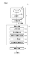
図1は、本発明の実施の形態に従う画像処理装置1の基本的構成を示すブロック図である。図1を参照して、画像処理装置1は、撮像部2と、画像処理部3と、画像出力部4とを含む。図1に示す画像処理装置1においては、撮像部2が被写体を撮像することで画像(以下、「入力画像」とも称す。)を取得し、画像処理部3がこの取得された入力画像に対して後述するような画像処理を行なうことで、当該入力画像に含まれるぼけを補正する。そして、画像出力部4は、この補正後の入力画像(以下、単に「補正後画像」とも称す。)を表示デバイスなどへ出力する。
(B1: Basic configuration)
FIG. 1 is a block diagram showing a basic configuration of an image processing apparatus 1 according to the embodiment of the present invention. With reference to FIG. 1, the image processing apparatus 1 includes an imaging unit 2, an image processing unit 3, and an image output unit 4. In the image processing apparatus 1 shown in FIG. 1, the image capturing unit 2 captures an image of a subject to acquire an image (hereinafter also referred to as “input image”), and the image processing unit 3 performs an operation on the acquired input image. By performing image processing as will be described later, blur included in the input image is corrected. Then, the image output unit 4 outputs the corrected input image (hereinafter also simply referred to as “corrected image”) to a display device or the like.
撮像部2は、対象物(被写体)を撮像して入力画像を生成する。より具体的には、撮像部2は、カメラ22と、カメラ22と接続されたA/D(Analog to Digital)変換部24とを含む。A/D変換部24は、カメラ22により撮像された被写体を示す入力画像を出力する。
The imaging unit 2 captures an object (subject) and generates an input image. More specifically, the imaging unit 2 includes a camera 22 and an A / D (Analog to Digital) conversion unit 24 connected to the camera 22. The A / D converter 24 outputs an input image indicating the subject imaged by the camera 22.
カメラ22は、被写体を撮像するための光学系であるレンズ22aと、レンズ22aにより集光された光を電気信号に変換するデバイスである撮像素子22bとを含む。A/D変換部24は、撮像素子22bから出力される被写体を示す映像信号(アナログ電気信号)をデジタル信号に変換して出力する。撮像部2はさらに、各部分を制御するための制御処理回路などを含み得る。
The camera 22 includes a lens 22a that is an optical system for imaging a subject, and an image sensor 22b that is a device that converts light collected by the lens 22a into an electrical signal. The A / D converter 24 converts a video signal (analog electrical signal) indicating a subject output from the image sensor 22b into a digital signal and outputs the digital signal. The imaging unit 2 may further include a control processing circuit for controlling each part.
画像処理部3は、撮像部2によって取得された入力画像に対して、本実施の形態に従う画像処理方法を実施することで、当該入力画像に含まれるぼけを補正する。より具体的には、画像処理部3は、LPF(Low Pass Filter:ローパスフィルター)処理部30と、色空間変換部32と、濃淡方向相関度算出部34と、エッジ補正部36と、RGB補正画像生成部38とを含む。
The image processing unit 3 corrects the blur included in the input image by performing the image processing method according to the present embodiment on the input image acquired by the imaging unit 2. More specifically, the image processing unit 3 includes an LPF (Low Pass Filter) processing unit 30, a color space conversion unit 32, a light / dark direction correlation calculation unit 34, an edge correction unit 36, and an RGB correction. And an image generation unit 38.
LPF処理部30は、処理対象の入力画像に対して低周波数成分を抽出する。
色空間変換部32は、処理対象の入力画像の色空間を変換する。具体的には、色空間変換部32は、RGB色空間の入力画像をYCrCb色空間の画像に変換する。
The LPF processing unit 30 extracts a low frequency component from the input image to be processed.
The color space conversion unit 32 converts the color space of the input image to be processed. Specifically, the color space conversion unit 32 converts an input image in the RGB color space into an image in the YCrCb color space.
濃淡方向相関度算出部34は、処理対象の入力画像についての濃淡方向相関度を算出する。この濃淡方向相関度の詳細については後述する。
The light / dark direction correlation calculation unit 34 calculates the light / dark direction correlation degree for the input image to be processed. The details of the light / dark direction correlation will be described later.
エッジ補正部36は、入力画像のぼけを補正するためのエッジ補正を行なう。
RGB補正画像生成部38は、エッジ補正後の入力画像をRGB色空間の画像に再度変換して出力する。
The edge correction unit 36 performs edge correction for correcting blur of the input image.
The RGB correction image generation unit 38 converts the input image after the edge correction again into an image in the RGB color space and outputs it.
画像出力部4は、画像処理部3によって生成される補正後画像の画像を表示デバイスなどへ出力する。
The image output unit 4 outputs the corrected image generated by the image processing unit 3 to a display device or the like.
各部の処理動作の詳細については、後述する。
図1に示す画像処理装置1は、各部を独立に構成することもできるが、汎用的には、以下に説明するデジタルカメラやパーソナルコンピューターなどとして具現化される場合が多い。そこで、本実施の形態に従う画像処理装置1の具現化例について説明する。
Details of the processing operation of each unit will be described later.
The image processing apparatus 1 shown in FIG. 1 can be configured independently, but is generally embodied as a digital camera or a personal computer described below for general purposes. Therefore, an implementation example of the image processing apparatus 1 according to the present embodiment will be described.
(b2:具現化例1)
図2は、図1に示す画像処理装置1を具現化したデジタルカメラ100の構成を示すブロック図である。図2において、図1に示す画像処理装置1を構成するそれぞれのブロックに対応するコンポーネントには、図1と同一の参照符号を付している。
(B2: Implementation example 1)
FIG. 2 is a block diagram showing a configuration of a digital camera 100 that embodies the image processing apparatus 1 shown in FIG. 2, components corresponding to the respective blocks constituting the image processing apparatus 1 shown in FIG. 1 are denoted by the same reference numerals as those in FIG. 1.
図2を参照して、デジタルカメラ100は、CPU(Central Processing Unit)102と、デジタル処理回路104と、画像表示部108と、カードインターフェイス(I/F)110と、記憶部112と、ズーム機構114と、光学系120とを含む。
Referring to FIG. 2, a digital camera 100 includes a CPU (Central Processing Unit) 102, a digital processing circuit 104, an image display unit 108, a card interface (I / F) 110, a storage unit 112, and a zoom mechanism. 114 and the optical system 120.
CPU102は、予め格納されたプログラムなどを実行することで、デジタルカメラ100の全体を制御する。デジタル処理回路104は、本実施の形態に従う画像処理を含む各種のデジタル処理を実行する。デジタル処理回路104は、典型的には、DSP(Digital Signal Processor)、ASIC(Application Specific Integrated Circuit)、LSI(Large Scale Integration)、FPGA(Field-Programmable Gate Array)などによって構成される。このデジタル処理回路104は、図1に示す画像処理部3が提供する機能を実現するための画像処理回路106を含む。
The CPU 102 controls the entire digital camera 100 by executing a program stored in advance. The digital processing circuit 104 executes various digital processes including image processing according to the present embodiment. The digital processing circuit 104 is typically a DSP (Digital Signal Processor), an ASIC (Application Specific Integrated Circuit), an LSI (Large Scale Integration), an FPGA (Field-Programmable), or the like. The digital processing circuit 104 includes an image processing circuit 106 for realizing the functions provided by the image processing unit 3 shown in FIG.
画像表示部108は、光学系120により提供される入力画像、デジタル処理回路104(画像処理回路106)によって生成される出力画像、デジタルカメラ100に係る各種設定情報、および、制御用GUI(Graphical User Interface)画面などを表示する。
The image display unit 108 includes an input image provided by the optical system 120, an output image generated by the digital processing circuit 104 (image processing circuit 106), various setting information related to the digital camera 100, and a control GUI (Graphical User). Interface) screen or the like is displayed.
カードインターフェイス(I/F)110は、画像処理回路106によって生成された画像データを記憶部112へ書き込み、あるいは、記憶部112から画像データなどを読み出すためのインターフェイスである。記憶部112は、画像処理回路106によって生成された画像データや各種情報(デジタルカメラ100の制御パラメータや動作モードなどの設定値)を格納する記憶デバイスである。この記憶部112は、フラッシュメモリ、光学ディスク、磁気ディスクなどからなり、データを不揮発的に記憶する。
The card interface (I / F) 110 is an interface for writing image data generated by the image processing circuit 106 to the storage unit 112 or reading image data or the like from the storage unit 112. The storage unit 112 is a storage device that stores image data generated by the image processing circuit 106 and various information (setting values such as control parameters and operation modes of the digital camera 100). The storage unit 112 includes a flash memory, an optical disk, a magnetic disk, and the like, and stores data in a nonvolatile manner.
ズーム機構114は、ユーザー操作などに応じて、光学系120の撮像倍率を変更する機構である。ズーム機構114は、典型的には、サーボモーターなどを含み、光学系120を構成するレンズ群を駆動することで、焦点距離を変化させる。
The zoom mechanism 114 is a mechanism that changes the imaging magnification of the optical system 120 in accordance with a user operation or the like. The zoom mechanism 114 typically includes a servo motor or the like, and changes the focal length by driving a lens group constituting the optical system 120.
光学系120は、被写体を撮像することで入力画像を生成する。
図2に示すデジタルカメラ100は、本実施の形態に従う画像処理装置1の全体を単体の装置として実装したものである。すなわち、ユーザーは、デジタルカメラ100を用いて被写体を撮像することで、画像表示部108において当該被写体を立体的に視認することができる。
The optical system 120 generates an input image by imaging a subject.
A digital camera 100 shown in FIG. 2 is obtained by mounting the entire image processing apparatus 1 according to the present embodiment as a single apparatus. That is, the user can visually recognize the subject in a three-dimensional manner on the image display unit 108 by imaging the subject using the digital camera 100.
(b3:具現化例2)
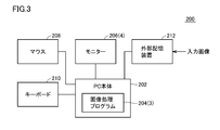
図3は、図1に示す画像処理装置1を具現化したパーソナルコンピューター200の構成を示すブロック図である。図3に示すパーソナルコンピューター200では、入力画像を取得するための撮像部2が搭載されておらず、任意の撮像部2によって取得された入力画像が外部から入力される構成となっている。このような構成であっても、本発明の実施の形態に従う画像処理装置1に含まれ得る。なお、図3においても、図1に示す画像処理装置1を構成するそれぞれのブロックに対応するコンポーネントには、図1と同一の参照符号を付している。
(B3: Implementation example 2)
FIG. 3 is a block diagram showing a configuration of a personal computer 200 that embodies the image processing apparatus 1 shown in FIG. In the personal computer 200 shown in FIG. 3, the imaging unit 2 for acquiring an input image is not mounted, and an input image acquired by an arbitrary imaging unit 2 is input from the outside. Even such a configuration can be included in the image processing apparatus 1 according to the embodiment of the present invention. In FIG. 3 as well, components corresponding to blocks constituting the image processing apparatus 1 shown in FIG. 1 are denoted by the same reference numerals as those in FIG.
図3を参照して、パーソナルコンピューター200は、パーソナルコンピューター本体202と、モニター206と、マウス208と、キーボード210と、外部記憶装置212とを含む。
3, the personal computer 200 includes a personal computer main body 202, a monitor 206, a mouse 208, a keyboard 210, and an external storage device 212.
パーソナルコンピューター本体202は、典型的には、汎用的なアーキテクチャーに従う汎用コンピューターであり、基本的な構成要素として、CPU、RAM(Random Access Memory)、ROM(Read Only Memory)などを含む。パーソナルコンピューター本体202は、図1に示す画像処理部3が提供する機能を実現するための画像処理プログラム204が実行可能になっている。このような画像処理プログラム204は、CD-ROM(Compact Disk-Read Only Memory)などの記憶媒体に格納されて流通し、あるいは、ネットワークを介してサーバー装置から配信される。そして、画像処理プログラム204は、パーソナルコンピューター本体202のハードディスクなどの記憶領域内に格納される。
The personal computer main body 202 is typically a general-purpose computer according to a general-purpose architecture, and includes a CPU, a RAM (Random Access Memory), a ROM (Read Only Memory), and the like as basic components. The personal computer main body 202 can execute an image processing program 204 for realizing a function provided by the image processing unit 3 shown in FIG. Such an image processing program 204 is stored and distributed in a storage medium such as a CD-ROM (Compact Disk-Read Only Memory), or distributed from a server device via a network. The image processing program 204 is stored in a storage area such as a hard disk of the personal computer main body 202.
このような画像処理プログラム204は、パーソナルコンピューター本体202で実行されるオペレーティングシステム(OS)の一部として提供されるプログラムモジュールのうち必要なモジュールを、所定のタイミングおよび順序で呼出して処理を実現するように構成されてもよい。この場合、画像処理プログラム204自体には、OSが提供するモジュールは含まれず、OSと協働して画像処理が実現される。また、画像処理プログラム204は、単体のプログラムではなく、何らかのプログラムの一部に組込まれて提供されてもよい。このような場合にも、画像処理プログラム204自体には、当該何らかのプログラムにおいて共通に利用されるようなモジュールは含まれず、当該何らかのプログラムと協働して画像処理が実現される。このような一部のモジュールを含まない画像処理プログラム204であっても、本実施の形態に従う画像処理装置1の趣旨を逸脱するものではない。
Such an image processing program 204 implements processing by calling necessary modules among program modules provided as part of an operating system (OS) executed by the personal computer main body 202 at a predetermined timing and order. It may be configured as follows. In this case, the image processing program 204 itself does not include a module provided by the OS, and image processing is realized in cooperation with the OS. Further, the image processing program 204 may be provided by being incorporated in a part of some program instead of a single program. Even in such a case, the image processing program 204 itself does not include a module that is commonly used in the program, and image processing is realized in cooperation with the program. Even such an image processing program 204 that does not include some modules does not depart from the spirit of the image processing apparatus 1 according to the present embodiment.
もちろん、画像処理プログラム204によって提供される機能の一部または全部を専用のハードウェアによって実現してもよい。
Of course, some or all of the functions provided by the image processing program 204 may be realized by dedicated hardware.
モニター206は、オペレーティングシステム(OS)が提供するGUI画面、画像処理プログラム204によって生成される画像などを表示する。
The monitor 206 displays a GUI screen provided by an operating system (OS), an image generated by the image processing program 204, and the like.
マウス208およびキーボード210は、それぞれユーザー操作を受付け、その受付けたユーザー操作の内容をパーソナルコンピューター本体202へ出力する。
The mouse 208 and the keyboard 210 each accept a user operation and output the contents of the accepted user operation to the personal computer main body 202.
外部記憶装置212は、何らかの方法で取得された入力画像を格納しており、この入力画像をパーソナルコンピューター本体202へ出力する。外部記憶装置212としては、フラッシュメモリ、光学ディスク、磁気ディスクなどのデータを不揮発的に記憶するデバイスが用いられる。
The external storage device 212 stores an input image acquired by some method, and outputs this input image to the personal computer main body 202. As the external storage device 212, a device that stores data in a nonvolatile manner such as a flash memory, an optical disk, or a magnetic disk is used.
図3に示すパーソナルコンピューター200は、本実施の形態に従う画像処理装置1の一部を単体の装置として実装したものである。
A personal computer 200 shown in FIG. 3 is obtained by mounting a part of the image processing apparatus 1 according to the present embodiment as a single apparatus.
<C.色収差>
本実施の形態に従う画像処理装置および画像処理方法では、典型的には、光学系に生じる色収差(軸上色収差)を補正する。
<C. Chromatic aberration>
In the image processing apparatus and the image processing method according to the present embodiment, typically, chromatic aberration (axial chromatic aberration) generated in the optical system is corrected.
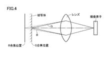
図4は、本発明の実施の形態に従う画像処理装置および画像処理方法が補正の対象とする色収差を説明するための図である。図4に示すように、色収差は、レンズを透過する光の屈折率が波長によって異なるために生じる現象である。例えば、撮像素子がR(赤色)、G(緑色)、B(青色)の3色に感度を有している場合に、Gでピント合わせしたとする。すなわち、Gに対応する波長でみれば、被写体の表面位置(目的とする位置)で合焦することになる(G合焦位置)。これに対して、RおよびBに対応する波長でみれば、レンズにおけるGに対応する波長の屈折率とは異なる屈折率が生じるため、被写体の表面位置とは異なる位置で合焦することになる(R合焦位置)。
FIG. 4 is a diagram for explaining chromatic aberration to be corrected by the image processing apparatus and the image processing method according to the embodiment of the present invention. As shown in FIG. 4, chromatic aberration is a phenomenon that occurs because the refractive index of light that passes through a lens differs depending on the wavelength. For example, when the image sensor has sensitivity to three colors of R (red), G (green), and B (blue), it is assumed that the focus is adjusted with G. In other words, when viewed at a wavelength corresponding to G, focusing is performed at the surface position (target position) of the subject (G focusing position). On the other hand, when viewed at wavelengths corresponding to R and B, a refractive index different from the refractive index of the wavelength corresponding to G in the lens is generated, so that focusing is performed at a position different from the surface position of the subject. (R in-focus position).
このように、光に含まれる波長成分によって合焦する位置が異なる状態を色収差といい、これによって、入力画像のG成分については、ぼけが生じないが、R成分については、ぼけが生じ得る。本実施の形態においては、このようなぼけを補正する画像処理方法を提供する。
As described above, a state in which the in-focus position differs depending on the wavelength component included in the light is referred to as chromatic aberration. As a result, no blur occurs in the G component of the input image, but blur may occur in the R component. In the present embodiment, an image processing method for correcting such blur is provided.
すなわち、本実施の形態においては、光学系の軸上色収差などのために、ある色成分(例えば、G)には、ぼけは発生していないが、他の色成分(例えば、RやB)には、ぼけが発生している画像について、その発生しているぼけを補正する処理を想定している。このぼけの補正は、GとRまたはBとの間のMTF(Modulation Transfer Function:光学伝達関数)特性の違いを補正することを意味する。
That is, in this embodiment, due to axial chromatic aberration of the optical system, blur is not generated in a certain color component (for example, G), but other color components (for example, R and B) are not generated. Is assumed to be processing for correcting the blurring of an image in which blurring occurs. This blur correction means correcting a difference in MTF (Modulation Transfer Function) characteristics between G and R or B.
<D.関連する画像処理方法>
まず、本実施の形態に従う画像処理方法の内容についての理解を容易にするために、本発明に関連する画像処理方法の内容について先に説明する。
<D. Related image processing method>
First, in order to facilitate understanding of the content of the image processing method according to the present embodiment, the content of the image processing method related to the present invention will be described first.
図5は、本発明に関連する画像処理方法の手順を示すフローチャートである。本発明に関連する画像処理方法(以下、単に「関連技術」とも称す。)においては、一例として、入力画像に含まれるGの高周波成分を、Y(輝度)の高周波成分として代用することで、ぼけを補正することを考える。
FIG. 5 is a flowchart showing the procedure of the image processing method related to the present invention. In the image processing method related to the present invention (hereinafter also simply referred to as “related technology”), as an example, by replacing the high frequency component of G included in the input image as the high frequency component of Y (luminance), Consider correcting for blur.
より具体的には、図5を参照して、まず入力画像を取得する処理(ステップS1)が実行される。この入力画像は、それを構成する各画素がR濃淡値、G濃淡値、B濃淡値の3次元の濃淡値で定義されているとする。続いて、当該取得した入力画像に含まれる色成分(R、G、B)のうち基準となる色成分(典型的には、G)についての高周波成分を取得する処理(ステップS2)が実行される。
More specifically, referring to FIG. 5, first, a process of acquiring an input image (step S1) is executed. In this input image, it is assumed that each pixel constituting the input image is defined by a three-dimensional gray value of R gray value, G gray value, and B gray value. Subsequently, a process (step S2) of acquiring a high frequency component for a reference color component (typically G) among the color components (R, G, B) included in the acquired input image is executed. The
続いて、入力画像のRGB色空間をYCrCB色空間へ変換する処理が実行される(ステップS3)。そして、ステップS2において取得された基準となる色成分についての高周波成分を用いて、ステップS3において取得されたYCrCB色空間の入力画像に対する補正処理が実行される(ステップS8)。そして、ステップS8による補正後の入力画像(YCrCB色空間)を再度RGB色空間へ変換する処理が実行され(ステップS9)、この処理によって得られた補正後画像が出力される(ステップS10)。そして、処理は終了する。
Subsequently, a process of converting the RGB color space of the input image into the YCrCB color space is executed (step S3). And the correction process with respect to the input image of YCrCB color space acquired in step S3 is performed using the high frequency component about the reference | standard color component acquired in step S2 (step S8). Then, the process of converting the corrected input image (YCrCB color space) in step S8 into the RGB color space is executed again (step S9), and the corrected image obtained by this process is output (step S10). Then, the process ends.
(d1:入力画像の取得(ステップS1))
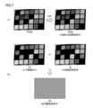
画像処理装置は、カメラで被写体を撮像するなどして、入力画像を取得する。図6は、本発明に関連する画像処理方法の処理対象となる入力画像の一例を示す図である。図6(a)には、RGB色空間で表現した入力画像(RGB0)の一例を示し、図6(b),(c),(d)には、R、G、Bの各濃淡画像(R0、G0、B0)の一例を示す。
(D1: Acquisition of input image (step S1))
The image processing apparatus acquires an input image by capturing a subject with a camera. FIG. 6 is a diagram showing an example of an input image to be processed by the image processing method related to the present invention. FIG. 6A shows an example of an input image (RGB0) expressed in the RGB color space. FIGS. 6B, 6C, and 6D show R, G, and B grayscale images ( An example of R0, G0, B0) is shown.
なお、図6には、一例として、750×500画素のサイズの画像を示す。
(d2:高周波成分の取得(ステップS2))
画像処理装置は、処理対象の入力画像に含まれる色成分(R、G、B)のうち基準となる色成分(典型的には、G)についての高周波成分を取得する。具体的には、入力画像に対してLPF(ローパスフィルター)をかけて低周波成分を抽出するとともに、入力画像からこの抽出した低周波成分を減算することで、高周波成分を抽出する。
FIG. 6 shows an image having a size of 750 × 500 pixels as an example.
(D2: Acquisition of high frequency component (step S2))
The image processing apparatus acquires a high frequency component for a reference color component (typically G) among color components (R, G, B) included in an input image to be processed. Specifically, a low frequency component is extracted by applying an LPF (low pass filter) to the input image, and a high frequency component is extracted by subtracting the extracted low frequency component from the input image.
なお、補正に用いる高周波成分の波長範囲については、予め定めておくことができる。このような波長範囲としては、補正対象の色成分のMTF特性のうち、基準となる色成分のMTF特性に比較して劣化している周波数帯域と設定することができる。すなわち、補正の対象となる高周波成分としては、少なくとも2色間で比較し、MTF特性がより悪い周波数帯域に設定することができる。
It should be noted that the wavelength range of the high-frequency component used for correction can be determined in advance. Such a wavelength range can be set to a frequency band that is degraded as compared with the MTF characteristics of the reference color component among the MTF characteristics of the color component to be corrected. That is, as a high frequency component to be corrected, at least two colors can be compared and set to a frequency band having a worse MTF characteristic.
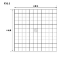
図7は、本発明に関連する画像処理方法の高周波成分の抽出処理を説明するための図である。図8は、LPFの一例を示す図である。
FIG. 7 is a diagram for explaining high-frequency component extraction processing of the image processing method related to the present invention. FIG. 8 is a diagram illustrating an example of an LPF.
図7(a)を参照して、まず、画像処理装置は、入力画像(RGB0)に対してLPFをかける。LPFとしては、例えば、図8に示すような11画素×11画素での平均化フィルタを採用することができる。なお、LPFとしては、抽出したい周波数や画像サイズなどの条件に応じて、フィルタサイズを変更してもよいし、ガウシアンフィルタなどの重み付け平均を用いる方式であってもよい。
Referring to FIG. 7A, first, the image processing apparatus applies LPF to the input image (RGB0). As the LPF, for example, an averaging filter with 11 pixels × 11 pixels as shown in FIG. 8 can be adopted. As the LPF, the filter size may be changed in accordance with conditions such as the frequency to be extracted and the image size, or a weighted average such as a Gaussian filter may be used.
このLPF処理によって、図7(a)に示すような、入力画像の低周波成分(RGBL)が取得される。図7(a)には、説明の便宜上、RGB色空間で表現した入力画像(RGB0)の低周波成分(RGBL)を示すが、目的とする色(本例では、G)の濃淡画像に対してのみ、LPFをかけてもよい。
The low-frequency component (RGBL) of the input image as shown in FIG. 7A is acquired by this LPF process. FIG. 7A shows the low-frequency component (RGBL) of the input image (RGB0) expressed in the RGB color space for convenience of explanation. For the grayscale image of the target color (G in this example), FIG. Only the LPF may be applied.
次に、図7(b)に示すように、入力画像のG(G0)から当該Gの低周波成分(GL)を減算することでと、入力画像のGの高周波成分(GH)が取得される。すなわち、入力画像からGの高周波成分が取り出される。
Next, as shown in FIG. 7B, by subtracting the low frequency component (GL) of G from the G (G0) of the input image, the high frequency component (GH) of G of the input image is acquired. The That is, the high frequency component of G is extracted from the input image.
(d3:YCrCB色空間への色変換処理(ステップS3))
画像処理装置は、RGB色空間の入力画像およびその低周波成分のそれぞれを、事後の補正処理のために、YCrCb色空間へ変換する。
(D3: Color conversion process to YCrCB color space (step S3))
The image processing device converts each of the input image in the RGB color space and the low frequency component thereof to the YCrCb color space for subsequent correction processing.
図9は、本発明に関連する画像処理方法におけるYCrCb色空間への変換処理を説明するための図である。図9(a)に示すように、RGB色空間の入力画像(RGB0)がYCrCb色空間へ変換される。この色変換処理によって、輝度成分(Y0)および2つの色相成分(Cr0、Cb0)が生成される。
FIG. 9 is a diagram for explaining the conversion process to the YCrCb color space in the image processing method related to the present invention. As shown in FIG. 9A, the input image (RGB0) in the RGB color space is converted into the YCrCb color space. By this color conversion process, a luminance component (Y0) and two hue components (Cr0, Cb0) are generated.
また、図9(b)に示すように、入力画像の低周波成分(RGBL)についても、YCrCb色空間へ変換される。この色変換処理によって、輝度成分(YL)および2つの色相成分が生成されるが、事後の処理では、入力画像の低周波成分(RGBL)の輝度成分(YL)のみが必要となるため、それ以外については図示していない。
Also, as shown in FIG. 9B, the low frequency component (RGBL) of the input image is also converted to the YCrCb color space. This color conversion process generates a luminance component (YL) and two hue components. However, in the subsequent process, only the luminance component (YL) of the low frequency component (RGBL) of the input image is required. Other than that is not shown.
(d4:YCrCB色空間の入力画像に対する補正処理(ステップS8))
次に、画像処理装置は、YCrCB色空間の入力画像に対して補正処理を行なう。すなわち、画像処理装置は、入力画像のGの高周波成分(GH)を入力画像のY(輝度)へ移植する。
(D4: Correction Process for Input Image in YCrCB Color Space (Step S8))
Next, the image processing apparatus performs correction processing on the input image in the YCrCB color space. That is, the image processing apparatus transplants the high frequency component (GH) of G of the input image to Y (luminance) of the input image.
図10は、本発明に関連する画像処理方法における入力画像に対する補正処理を説明するための図である。図11は、本発明に関連する画像処理方法における入力画像に対する補正処理による効果を説明するための図である。
FIG. 10 is a diagram for explaining a correction process for an input image in the image processing method related to the present invention. FIG. 11 is a diagram for explaining the effect of the correction process on the input image in the image processing method related to the present invention.
図10に示すように、画像処理装置は、入力画像のY(輝度)の高周波成分の代わりに、入力画像のGの高周波成分(GH)を代用して、入力画像のY(輝度)を補正する。入力画像のY(輝度)の高周波成分を差し替えるため、入力画像のY(輝度)から高周波成分を取り除いた低周波成分(YL)に、入力画像のGの高周波成分(GH)を加算し、補正後の入力画像の輝度である補正後Y(Y’)を生成する。
As shown in FIG. 10, the image processing apparatus corrects Y (luminance) of the input image by substituting the high frequency component (GH) of G of the input image instead of the high frequency component of Y (luminance) of the input image. To do. In order to replace the high-frequency component of Y (luminance) in the input image, the high-frequency component (GH) of the input image is added to the low-frequency component (YL) obtained by removing the high-frequency component from Y (luminance) of the input image. A corrected Y (Y ′) that is the luminance of the subsequent input image is generated.
図11(a)と図11(b)とを比較するとわかるように、上述した入力画像に対する補正処理によって、入力画像の元のY(輝度)に比較して、文字部やパッチの境界部などで、エッジがシャープに補正されていることがわかる。
As can be seen by comparing FIG. 11 (a) and FIG. 11 (b), the correction processing for the input image described above makes it possible to compare the character image, the boundary of the patch, and the like compared to the original Y (luminance) of the input image. It can be seen that the edge is corrected sharply.
(d5:RGB色空間への色変換処理(ステップS9))
最後に、画像処理装置は、補正後Y(Y’)を用いて、YCrCb色空間からRGB色空間へ戻すことで、補正後のRGB画像を生成する。
(D5: Color conversion process to RGB color space (step S9))
Finally, the image processing apparatus uses the corrected Y (Y ′) to return from the YCrCb color space to the RGB color space, thereby generating a corrected RGB image.
図12は、本発明に関連する画像処理方法におけるRGB色空間への色変換処理を説明するための図である。図12(a)および図12(b)に示すように、画像処理装置は、補正後Y(Y’)と元のCrおよびCbをそれぞれ加算することで、補正後のRおよびBを生成する。なお、Gについては、もともと基準となる色成分であり、補正の必要がないため、入力画像の元の値がそのまま使用される。
FIG. 12 is a diagram for explaining the color conversion processing to the RGB color space in the image processing method related to the present invention. As shown in FIGS. 12A and 12B, the image processing apparatus generates corrected R and B by adding corrected Y (Y ′) and original Cr and Cb, respectively. . Note that G is originally a reference color component and does not need to be corrected, so the original value of the input image is used as it is.
(d6:関連技術による補正結果)
図13は、本発明に関連する画像処理方法による補正結果の一例を示す図である。図14は、図13に示す補正結果の拡大図である。
(D6: Result of correction by related technology)
FIG. 13 is a diagram showing an example of a correction result by the image processing method related to the present invention. FIG. 14 is an enlarged view of the correction result shown in FIG.
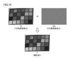
図13には、関連技術によって入力画像を補正して得られる結果の画像を示す。図13に示す補正後画像をみると概ねシャープ化されているように見えるが、図14に示すように、補正後画像を部分的に拡大すると、赤のパッチ部は、高周波成分を補正したにもかかわらず、逆にぼけてしまっていることがわかる。これは、図14の中段に示すように、補正によってR成分がぼけてしまうことにより生じる。
FIG. 13 shows an image obtained as a result of correcting the input image by the related technology. When the corrected image shown in FIG. 13 is viewed, the image appears to be sharpened. However, as shown in FIG. 14, when the corrected image is partially enlarged, the red patch portion corrects the high-frequency component. However, it turns out that it is blurred on the contrary. This is caused by the blurring of the R component due to the correction, as shown in the middle part of FIG.
<E.本実施の形態における解決手段>
本願発明者は、上述した関連技術において、図14に示すような課題が生じることを見出すとともに、その原因について新たな知見を得た。その上で、本願発明者は、この新たな知見に基づいて、本願の技術思想に想到したものである。以下、これらの内容について説明する。
<E. Solution in the present embodiment>
The inventor of the present application found out that the problem shown in FIG. 14 occurs in the related art described above, and obtained new knowledge about the cause. Based on this new knowledge, the inventor of the present application has arrived at the technical idea of the present application. Hereinafter, these contents will be described.
図15および図16は、本発明に関連する画像処理方法による補正によって生じる課題を説明するための図である。図17は、本発明の実施の形態において採用する濃淡方向相関度を説明するための図である。
15 and 16 are diagrams for explaining a problem caused by correction by the image processing method related to the present invention. FIG. 17 is a diagram for explaining the grayscale direction correlation employed in the embodiment of the present invention.
図15(a)に示すように、関連技術による補正の結果得られる補正後画像(RGB’)についてみれば、グレイのパッチ部については、補正によってシャープ(ぼけが解消)になっているが、赤のパッチ部については、補正によってぼけの度合いが増している。
As shown in FIG. 15 (a), regarding the post-correction image (RGB ′) obtained as a result of the correction by the related technique, the gray patch portion is sharpened (blur is eliminated) by the correction. About the red patch part, the degree of blur is increased by the correction.
図15(b)に示すように、入力画像のR成分およびG成分において、それぞれの色について、パッチ部とその周辺部とを比較する。まず、グレイについては、R成分およびG成分とも、パッチ部の内部が薄い一方で、その周辺部は濃くなっており、濃淡変化についての関係が同じである。これに対して、赤については、R成分では、パッチ部の内部が濃い一方で、その周辺部は薄くなっており、G成分では、パッチ部の内部が薄い一方で、その周辺部は濃くなっている。すなわち、赤については、パッチ部とその周辺との間の濃淡変換の関係がR成分とG成分との間で逆転している。
As shown in FIG. 15B, in the R component and G component of the input image, the patch portion and its peripheral portion are compared for each color. First, for gray, both the R component and the G component are thin in the inside of the patch portion, but the periphery thereof is dark, and the relationship regarding the change in light and shade is the same. On the other hand, in the case of red, the inside of the patch part is dark in the R component, but the peripheral part is thin, and in the G component, the inside of the patch part is thin, but the peripheral part is dark. ing. That is, with respect to red, the relationship of light and shade conversion between the patch portion and the periphery thereof is reversed between the R component and the G component.
本実施の形態において、入力画像の同一範囲における、異なる色成分の間での濃淡変化の関係を「濃淡方向相関度」と称す。そして、上述のグレイのように、異なる色成分の間での濃淡変化が同一または類似している状態を「正相関」と称し、上述の赤のように、異なる色成分の間での濃淡変化が異なっているまたは反対になっている状態を「負相関」と称す。すなわち、本実施の形態に従う解決手段は、入力画像における注目領域について、第1の色成分と第2の色成分の濃淡方向が同一方向であるか逆方向であるかを示す濃淡方向相関度を算出する処理を含む。
In the present embodiment, the relationship of light and shade changes between different color components in the same range of the input image is referred to as “light and dark direction correlation degree”. A state in which the shade change between different color components is the same or similar, such as the above gray, is called “positive correlation”, and the shade change between different color components, as in the above red. A state in which is different or opposite is referred to as “negative correlation”. That is, the solving means according to the present embodiment calculates a gray-scale correlation degree indicating whether the first color component and the second color component are in the same direction or in the opposite direction for the attention area in the input image. Includes processing to calculate.
図16(a)に示すように、「濃淡方向相関度」が高い、つまり色成分の間で「正相関」があるときには、補正によって、エッジを立てて、シャープになるように働く。これに対して、図16(b)に示すように、「濃淡方向相関度」が低い、つまり色成分の間で「負相関」があるときには、補正によって逆にエッジを鈍らせてしまう。
As shown in FIG. 16A, when the “shading direction correlation degree” is high, that is, when there is “positive correlation” between the color components, the correction works to make the edge sharper. On the other hand, as shown in FIG. 16B, when the “shading direction correlation degree” is low, that is, when there is “negative correlation” between the color components, the edge is dulled by the correction.
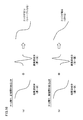
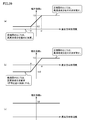
濃淡方向相関度に係る正相関および負相関の概念図を図17に示す。図17(a)に示すように、R成分およびG成分の両方において、対応する部分が濃い状態から薄い状態へ変化するような場合は、正相関となる。これに対して、図17(b)に示すように、R成分において、対応する部分が濃い状態から薄い状態へ変化する一方で、G成分において、対応する部分が薄い状態から濃い状態へ変化するような場合は、負相関となる。
FIG. 17 shows a conceptual diagram of the positive correlation and the negative correlation related to the grayscale direction correlation degree. As shown in FIG. 17A, in both the R component and the G component, when the corresponding portion changes from a dark state to a light state, a positive correlation is obtained. In contrast, as shown in FIG. 17B, in the R component, the corresponding portion changes from a dark state to a thin state, while in the G component, the corresponding portion changes from a thin state to a dark state. In such a case, a negative correlation is obtained.
本実施の形態においては、このような濃淡方向相関度を用いて、補正によってぼけを生じさせないように、補正に用いる高周波成分を適宜修正する。すなわち、本実施の形態に従う画像処理方法は、高周波成分を他の色成分(チャンネル)の高周波成分として代用する方法を採用した場合に生じる課題に向けられている。なお、上述の関連技術においては、入力画像のGの高周波成分をY(輝度)の高周波成分として用いることで、GをRとして代用することに相当している。
In the present embodiment, the high-frequency component used for correction is appropriately corrected so as not to cause blur due to the correction using such a gray-scale correlation. That is, the image processing method according to the present embodiment is directed to a problem that occurs when a method that substitutes a high-frequency component as a high-frequency component of another color component (channel) is employed. In the related art described above, using the high frequency component of G of the input image as the high frequency component of Y (luminance) corresponds to substituting G as R.
<F.実施の形態1>
次に、上述のような解決手段を用いた実施の形態1について説明する。実施の形態1に従う画像処理方法においても、一例として、入力画像に含まれるGの高周波成分をY(輝度)の高周波成分として代用する方法を想定する。
<F. Embodiment 1>
Next, Embodiment 1 using the above solution will be described. Also in the image processing method according to the first embodiment, as an example, a method is assumed in which a high frequency component of G included in an input image is substituted as a high frequency component of Y (luminance).
本発明の実施の形態1に従う画像処理装置は、複数の色成分で表現された入力画像を取得する機能と、入力画像における注目領域について、第1の色成分(典型的には、G)と第2の色成分(典型的には、R)の濃淡方向が同一方向であるか逆方向であるかを示す濃淡方向相関度を算出する機能と、注目領域について、第1の色成分の高周波成分を算出する機能とを有する。そして、画像処理装置は、高周波成分を用いて、算出された濃淡方向相関度に応じた方法で、注目領域についての補正対象の色成分を補正する。つまり、画像処理装置は、相関度算出部によって算出された濃淡方向相関度に応じた方法で、高周波成分算出部によって算出された第1の色成分の高周波成分を用いて注目領域についての第2の色成分を補正する。すなわち、本実施の形態1に従う画像処理装置は、少なくとも2色間の濃淡方向相関度を算出し、領域毎に高周波成分の用い方を切り替えて、ぼけを補正する。
The image processing apparatus according to the first embodiment of the present invention has a function of acquiring an input image expressed by a plurality of color components, and a first color component (typically G) for a region of interest in the input image. The function of calculating the shade direction correlation indicating whether the shade direction of the second color component (typically R) is the same direction or the opposite direction, and the high frequency of the first color component for the attention area And a function of calculating a component. Then, the image processing apparatus corrects the color component to be corrected for the attention area by using the high-frequency component by a method according to the calculated shade direction correlation degree. That is, the image processing apparatus uses the high-frequency component of the first color component calculated by the high-frequency component calculation unit in a method corresponding to the grayscale direction correlation degree calculated by the correlation degree calculation unit. The color component of is corrected. In other words, the image processing apparatus according to the first embodiment calculates the degree of contrast in at least two colors, and corrects the blur by switching the use of the high-frequency component for each region.
(f1:全体手順)
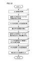
図18は、本発明の実施の形態1に従う画像処理方法の手順を示すフローチャートである。図18を参照して、まず入力画像を取得する処理(ステップS1)が実行される。続いて、当該取得した入力画像に含まれる色成分(R、G、B)のうち基準となる色成分(典型的には、G)についての高周波成分を取得する処理(ステップS2)が実行される。さらに、入力画像のRGB色空間をYCrCB色空間へ変換する処理が実行される(ステップS3)。このステップS1~S3の処理は、図5に示すステップS1~S3の処理と同様である。
(F1: Overall procedure)
FIG. 18 is a flowchart showing a procedure of the image processing method according to the first embodiment of the present invention. Referring to FIG. 18, first, a process for acquiring an input image (step S1) is executed. Subsequently, a process (step S2) of acquiring a high frequency component for a reference color component (typically G) among the color components (R, G, B) included in the acquired input image is executed. The Further, a process for converting the RGB color space of the input image into the YCrCB color space is executed (step S3). The processes in steps S1 to S3 are the same as the processes in steps S1 to S3 shown in FIG.
続いて、濃淡方向相関度の算出処理(ステップS4)が実行される。そして、基準となる色成分(典型的には、G)についての高周波成分から補正値を算出する処理(ステップS5)が実行される。そして、ステップS5において算出された基準となる色成分についての高周波成分を用いて、ステップS3において取得されたYCrCB色空間の入力画像に対する補正処理が実行される(ステップS6)。そして、ステップS6による補正後の入力画像(YCrCB色空間)を再度RGB色空間へ変換する処理が実行され(ステップS7)、この処理によって得られた補正後画像が出力される(ステップS10)。そして、処理は終了する。
Subsequently, a calculation process (step S4) of the light / dark direction correlation degree is executed. And the process (step S5) which calculates a correction value from the high frequency component about the color component (typically G) used as a reference | standard is performed. And the correction process with respect to the input image of the YCrCB color space acquired in step S3 is performed using the high frequency component about the reference color component calculated in step S5 (step S6). Then, the process of converting the input image (YCrCB color space) corrected in step S6 into the RGB color space is executed again (step S7), and the corrected image obtained by this process is output (step S10). Then, the process ends.
以下、主として、図18に示すステップS4~S7の処理内容について詳述する。なお、ステップS1~S3およびS10の処理内容については、上述の関連技術において説明した内容と同様であるので、詳細な説明は繰り返さない。
Hereinafter, the processing contents of steps S4 to S7 shown in FIG. 18 will be mainly described in detail. Since the processing contents of steps S1 to S3 and S10 are the same as those described in the related art described above, detailed description will not be repeated.
(f2:濃淡方向相関度の算出処理(ステップS4))
次に、濃淡方向相関度の算出処理の詳細について説明する。
(F2: Light / dark direction correlation degree calculation process (step S4))
Next, details of the calculation processing of the light / dark direction correlation will be described.
図19は、本発明の実施の形態1に従う画像処理方法における濃淡方向相関度の概要を示す図である。図20および図21は、本発明の実施の形態1に従う画像処理方法における濃淡方向相関度の算出処理の一過程を示す図である。図22は、本発明の実施の形態1に従う画像処理方法における濃淡方向相関度の算出結果の一例を示す図である。
FIG. 19 is a diagram showing an outline of the grayscale direction correlation degree in the image processing method according to the first embodiment of the present invention. FIG. 20 and FIG. 21 are diagrams showing a process in the grayscale direction correlation calculation process in the image processing method according to the first embodiment of the present invention. FIG. 22 is a diagram showing an example of a calculation result of the light / dark direction correlation degree in the image processing method according to the first embodiment of the present invention.
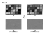
図18のステップS4においては、図19(a)に示すような、補正によってぼけが生じる領域の発生を回避するために、濃淡方向相関度を算出する。ここでは、入力画像のRについての濃淡方向相関度を算出するものとする。
In step S4 of FIG. 18, the gray-scale correlation is calculated in order to avoid the occurrence of a region where blur is caused by correction as shown in FIG. In this case, it is assumed that the gray level correlation degree for R of the input image is calculated.
上述したように、本実施の形態において「濃淡方向相関度」は、図19(b)に示すように、エッジ(濃淡変化が大きな部分)に正相関または負相関があるかを判断できるようなデータである。図19(b)には、濃淡方向相関度を2次元画像として表現している。この濃淡方向相関度において、「白」の部分は、エッジであって正相関が強いほど、データとしては正の大きな値をとる。一方、「黒」の部分は、エッジであって負相関が強いほど、データとしては負の大きな値をとる。また、「グレイ」の部分は、エッジでない部分か、あるいはエッジであっても相関がほとんどない部分となり、データとしては0近傍の値をとる。
As described above, in the present embodiment, the “shading direction correlation degree” is such that, as shown in FIG. 19B, it can be determined whether there is a positive correlation or a negative correlation at an edge (a portion where the change in shading is large). It is data. In FIG. 19B, the light / dark direction correlation is expressed as a two-dimensional image. In this density direction correlation, the “white” portion is an edge and takes a larger positive value as the positive correlation is stronger. On the other hand, the “black” portion is an edge and has a negative negative value as the negative correlation is strong. Further, the “gray” portion is a portion that is not an edge, or a portion that has little correlation even if it is an edge, and takes a value in the vicinity of 0 as data.
以下、図20~図22を参照して、濃淡方向相関度の算出処理の詳細について説明する。まず、図20に示すように、画像処理装置1は、入力画像のRおよびGの高周波成分(RHおよびGH)をそれぞれ算出する。この高周波成分の算出方法については、図7および図8を参照して説明したので、詳細な内容については繰り返さない。
Hereinafter, with reference to FIG. 20 to FIG. 22, the details of the calculation processing of the light / dark direction correlation degree will be described. First, as shown in FIG. 20, the image processing apparatus 1 calculates R and G high-frequency components (RH and GH) of an input image, respectively. Since this high-frequency component calculation method has been described with reference to FIGS. 7 and 8, the detailed contents will not be repeated.
次に、画像処理装置1は、Rの高周波成分(RH)とGの高周波成分(GH)との間で、相関値を算出する。すなわち、画像処理装置1は、2色の高周波成分を用いて濃淡方向相関度を算出する。このとき、濃淡方向相関度は、2色の高周波成分をパターンマッチングして得られた相関値を用いて算出される。
Next, the image processing apparatus 1 calculates a correlation value between the R high-frequency component (RH) and the G high-frequency component (GH). That is, the image processing apparatus 1 calculates the light and dark direction correlation degree using the high-frequency components of two colors. At this time, the light / dark direction correlation degree is calculated using a correlation value obtained by pattern matching of high-frequency components of two colors.
本実施の形態においては、一例として、Rの高周波成分(RH)とGの高周波成分(GH)とに対し、NCC(Normalized Cross Correlation)法を用いて、高周波成分の相関値としてNCC値が算出される。ここで、NCC法は、パターンマッチングの一種である。
In the present embodiment, as an example, the NCC value is calculated as the correlation value of the high frequency component using the NCC (Normalized Cross Correlation) method for the high frequency component (RH) of R and the high frequency component (GH) of G. Is done. Here, the NCC method is a kind of pattern matching.
ここで、図8に示すLPFと同じく、11画素×11画素のサイズであれば、以下の(1)式に従って、NCC値が算出される。
Here, similarly to the LPF shown in FIG. 8, if the size is 11 pixels × 11 pixels, the NCC value is calculated according to the following equation (1).
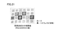
図20に示される高周波成分(RHおよびGH)についてのNCC値の結果は、図21に示すようになる。図21に示すNCC値の結果において、濃淡方向が同じところほど白っぽく表示されて、1.0に近い値を示し、逆の、濃淡方向が異なるところほど黒っぽく、-1.0に近い値を示すことになる。
The results of NCC values for the high frequency components (RH and GH) shown in FIG. 20 are as shown in FIG. In the result of the NCC value shown in FIG. 21, the same shade direction is displayed as whitish, indicating a value close to 1.0, and conversely, the difference in the shade direction is darker, indicating a value close to −1.0. It will be.
上述の(1)式に示すような11画素×11画素のすべて処理を行なう代わりに、2画素毎に計算を行なうなど、高速化のため処理を簡略化してもよい。また、処理サイズについても、LPFのサイズと同じである必要はなく、目的とするエッジの濃淡についての相関が適切に算出できるように、フィルタサイズを調整してよい。
Instead of performing all the processing of 11 pixels × 11 pixels as shown in the above equation (1), the processing may be simplified for speeding up such as calculation every two pixels. Also, the processing size does not have to be the same as the LPF size, and the filter size may be adjusted so that the correlation of the target edge density can be calculated appropriately.
このように、本実施の形態に従う画像処理装置は、基準となる色成分(典型的には、G)および補正対象の色成分(典型的には、R)に含まれる高周波成分に基づいて、濃淡方向相関度を算出する。より具体的には、本実施の形態に従う画像処理装置は、NCC法を用いて濃淡方向相関度を算出する。
As described above, the image processing apparatus according to the present embodiment is based on the high-frequency component included in the reference color component (typically G) and the color component to be corrected (typically R), The light / dark direction correlation is calculated. More specifically, the image processing apparatus according to the present embodiment calculates the light / dark direction correlation using the NCC method.
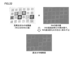
図21に示す高周波成分の相関値(NCC値の結果)には、エッジであるか否か(すなわち、濃淡変化が大きいか否か)の情報は含まれないので、RHの絶対値を掛け合わせることで、濃淡方向相関度が算出される。
Since the correlation value (result of NCC value) of the high-frequency component shown in FIG. 21 does not include information about whether or not it is an edge (that is, whether or not the change in shading is large), the absolute value of RH is multiplied. Thus, the light / dark direction correlation degree is calculated.
すなわち、図22に示すように、「高周波成分の相関値」と「RHの絶対値」(Rのエッジであるか否か(濃淡変化が大きいか否か)の情報)とを各画素について掛け合わせる処理が実行される。より具体的には、画像処理装置は、以下の(2)式に従って、高周波成分の相関値にRHの絶対値を掛け合わせることで、濃淡方向相関度を算出する。
That is, as shown in FIG. 22, “correlation value of high frequency component” and “absolute value of RH” (information on whether or not it is an edge of R (whether or not a change in shading is large)) are multiplied for each pixel. The matching process is executed. More specifically, the image processing apparatus calculates the light and dark direction correlation degree by multiplying the correlation value of the high frequency component by the absolute value of RH according to the following equation (2).
濃淡方向相関度=NCC×|RH| …(2)
ここでは、RのエッジがGのエッジに対してどのような相関があるかを算出しているため、RHの絶対値を用いている。すなわち、Rの高周波成分の絶対値がRの濃淡変化の大きさに相当する。
Density direction correlation = NCC × | RH | (2)
Here, since the R edge is calculated to correlate with the G edge, the absolute value of RH is used. That is, the absolute value of the high-frequency component of R corresponds to the magnitude of the change in shading of R.
このように、本実施の形態に従う画像処理装置は、相関値に第2の色成分(典型的には、R)の濃淡変化の大きさを乗じることで、濃淡方向相関度を算出する。
As described above, the image processing apparatus according to the present embodiment calculates the density direction correlation degree by multiplying the correlation value by the magnitude of the density change of the second color component (typically, R).
(f3:高周波成分から補正値の算出処理(ステップS5))
次に、基準となる色成分(典型的には、G)についての高周波成分から補正値を算出する処理(ステップS5)が実行される。
(F3: Correction value calculation process from high-frequency component (step S5))
Next, a process (step S5) of calculating a correction value from the high frequency component for the reference color component (typically G) is executed.
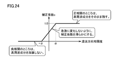
図23は、本発明の実施の形態1に従う補正用の高周波成分を算出するための処理を示す図である。図24は、本発明の実施の形態1に従う補正用の高周波成分を算出するための補正係数の一例を示す図である。
FIG. 23 is a diagram showing processing for calculating a high-frequency component for correction according to the first embodiment of the present invention. FIG. 24 is a diagram showing an example of a correction coefficient for calculating a high frequency component for correction according to the first embodiment of the present invention.
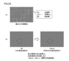
図23(a)に示すような濃淡方向相関度が算出されると、この算出された濃淡方向相関度を用いて、入力画像のRを補正するためのGの高周波成分(GHred)が算出される。より具体的には、図23(b)に示すような入力画像のGの高周波成分(GH)のうち、正相関を有する部分では高周波成分を残し、負相関を有する部分では高周波成分を加算しないように、Gの高周波成分(GH)を補正することで、入力画像のRを補正するためのGの高周波成分(GHred)を生成する。このGの高周波成分(GHred)の生成には、図24に示すような補正係数cを用いて、以下の(3)式に従って算出する。
When the gray level correlation degree as shown in FIG. 23A is calculated, a high frequency component (GHred) of G for correcting R of the input image is calculated using the calculated gray level correlation degree. The More specifically, among the high-frequency components (GH) of G of the input image as shown in FIG. 23B, the high-frequency component is left in the portion having a positive correlation, and the high-frequency component is not added in the portion having a negative correlation. As described above, by correcting the high frequency component (GH) of G, the high frequency component (GHred) of G for correcting R of the input image is generated. The G high-frequency component (GHred) is generated according to the following equation (3) using a correction coefficient c as shown in FIG.
GHred=GH×c …(3)
図24に示す補正係数cに関して、正相関のところはGの高周波成分をそのまま残すために、濃淡方向相関度がα(α>0)を超える場合には、補正係数c=1を採用する。一方、負相関のところはGの高周波成分を加算しないために、濃淡方向相関度が-αを下回る場合には、補正係数c=0を採用する。正相関と負相関との間で急激な変化を避けるために、濃淡方向相関度が-αからαの範囲にある場合には、補正係数を濃淡方向相関度についての一次関数に設定して、補正係数の変化を滑らかにしている。なお、ここでは濃淡方向相関度の閾値としてαと-αの絶対値が同じ値を用いたが、負相関の閾値としては、-αに限らず、任意の値β(β<0)を用いても構わない。
GHred = GH × c (3)
With respect to the correction coefficient c shown in FIG. 24, in the case of the positive correlation, the high-frequency component of G is left as it is, and when the gray level correlation degree exceeds α (α> 0), the correction coefficient c = 1 is adopted. On the other hand, since the high frequency component of G is not added at the negative correlation, the correction coefficient c = 0 is employed when the degree of correlation in the light and dark direction is below -α. To avoid a sharp change between positive and negative correlations, if the gray level correlation is in the range of -α to α, the correction coefficient is set to a linear function for the gray level correlation, The change of the correction coefficient is made smooth. Here, the same absolute value of α and −α is used as the threshold value of the light / dark direction correlation degree, but the negative correlation threshold value is not limited to −α, and an arbitrary value β (β <0) is used. It doesn't matter.
つまり、本実施の形態に従う補正処理においては、注目領域についての濃淡方向相関度が、第1の色成分と第2の色成分の濃淡方向が同一方向である正相関を示すときに、第2の色成分に対して第1の色成分の高周波成分を加算し、注目領域についての濃淡方向相関度が、第1の色成分と第2の色成分の濃淡方向が逆方向である負相関を示すときに、第1の色成分の高周波成分による第2の色成分の補正を行なわない。
In other words, in the correction processing according to the present embodiment, when the shade direction correlation degree for the attention area indicates a positive correlation in which the shade direction of the first color component and the second color component is the same direction, The high frequency component of the first color component is added to the color component of the first color component, and the gray level direction correlation degree for the region of interest has a negative correlation in which the gray level directions of the first color component and the second color component are opposite. When shown, the second color component is not corrected by the high frequency component of the first color component.
より具体的には、本実施の形態に従う補正処理においては、注目領域についての濃淡方向相関度が所定値α(α>0)を超えるときに正相関と判断し、注目領域についての濃淡方向相関度が所定値β(β<0)を下回るときに相関と判断し、注目領域についての濃淡方向相関度が所定値αから所定値βの範囲にあるときに、正相関の場合と比較して低減された第1の色成分の高周波成分を第2の色成分に対して加算する。
More specifically, in the correction processing according to the present embodiment, when the grayscale direction correlation degree for the attention area exceeds a predetermined value α (α> 0), it is determined as a positive correlation, and the grayscale direction correlation for the attention area is determined. When the degree falls below a predetermined value β (β <0), it is determined to be a correlation, and when the grayscale direction correlation degree for the region of interest is in the range from the predetermined value α to the predetermined value β, compared to the case of a positive correlation The reduced high frequency component of the first color component is added to the second color component.
(f4:入力画像に対する補正処理(ステップS6))
次に、上述のような処理によって算出された、入力画像のRを補正するためのGの高周波成分(GHred)を用いて、入力画像に対する補正処理が実行される。
(F4: Correction process for input image (step S6))
Next, the correction process for the input image is executed using the high-frequency component (GHred) of G for correcting the R of the input image calculated by the process as described above.
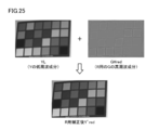
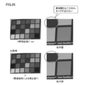
図25は、本発明の実施の形態1に従う画像処理方法における入力画像の補正処理を説明するための図である。図26は、図25に示す入力画像の補正処理による補正の効果を説明するための図である。
FIG. 25 is a diagram for describing an input image correction process in the image processing method according to the first embodiment of the present invention. FIG. 26 is a diagram for explaining the effect of correction by the input image correction processing shown in FIG.
図25を参照して、入力画像のRを補正するためのGの高周波成分(GHred)が入力画像のRの輝度(Y’red)へ移植される。すなわち、入力画像のRについては、Gの高周波成分(GHred)を用いて、R用の補正後の輝度(Y’red)が算出される。より具体的には、入力画像の輝度の低周波成分(YL)にGの高周波成分(GHred)が加算されることで、輝度(Y’red)が算出される。
Referring to FIG. 25, the high frequency component (GHred) of G for correcting the R of the input image is transplanted to the luminance (Y′red) of R of the input image. That is, for R of the input image, the corrected luminance (Y′red) for R is calculated using the high frequency component (GHred) of G. More specifically, the luminance (Y′red) is calculated by adding the high frequency component (GHred) of G to the low frequency component (YL) of the luminance of the input image.
図26に示すように、このような補正方法を採用することで、図15に示すような負相関が原因でぼけが発生していた赤のパッチ部のエッジに対しては、補正が行なわれず、上述のような問題は発生しない。すなわち、負相関の部分は、エッジが強調されない。
As shown in FIG. 26, by adopting such a correction method, correction is not performed on the edge of the red patch portion in which blur has occurred due to the negative correlation as shown in FIG. The above problems do not occur. That is, the edge of the negative correlation portion is not emphasized.
入力画像のGは補正の基準であるので、何らの補正もなされない。これに対して、入力画像のBについては、上述の関連技術と同様に、Gの高周波成分(GH)を用いて補正される。
* Since G in the input image is a reference for correction, no correction is made. On the other hand, B of the input image is corrected using the high frequency component (GH) of G, as in the related art described above.
但し、入力画像のBについても、上述の実施の形態1におけるRと同様に、入力画像のGとBとの間で濃淡方向相関度を算出するとともに、算出した濃淡方向相関度に基づいて、入力画像のBを補正するためのGの高周波成分(GHblue)を算出する。そして、この算出されたGの高周波成分(GHblue)を用いて、補正を行なうようにしてもよい。その手順の詳細は、上述したので繰り返さない。
However, with respect to B of the input image as well as R in the above-described first embodiment, the density direction correlation degree is calculated between G and B of the input image, and based on the calculated density direction correlation degree, A high frequency component (GHblue) of G for correcting B of the input image is calculated. Then, correction may be performed using the calculated G high-frequency component (GHblue). Details of the procedure have been described above and will not be repeated.
(f5:RGB色空間への変換処理(ステップS7))
最後に、画像処理装置は、R用の補正後の輝度(Y’red)を用いて、YCrCb色空間からRGB色空間へ戻すことで、補正後のRGB画像を生成する。
(F5: RGB color space conversion process (step S7))
Finally, the image processing apparatus generates a corrected RGB image by returning from the YCrCb color space to the RGB color space by using the corrected luminance (Y′red) for R.
図27は、本発明の実施の形態1に従う画像処理方法におけるRGB色空間への色変換処理を説明するための図である。図27に示すように、画像処理装置1は、R用の補正後の輝度(Y’red)と元のCrとを加算することで、補正後のR(R’’)を生成する。
FIG. 27 is a diagram for describing color conversion processing into the RGB color space in the image processing method according to the first embodiment of the present invention. As shown in FIG. 27, the image processing apparatus 1 generates corrected R (R ″) by adding the corrected luminance (Y′red) for R and the original Cr.
なお、Gについては、もともと基準となる色成分であり、補正の必要がないため、入力画像の元の値がそのまま使用される。また、Bについては、基本的には、図12(b)に示す関連技術と同様の手順で、輝度(Y’)と元のCbとを加算することで、補正後のB(B’)が生成される。但し、濃淡方向相関度に基づいて、入力画像のBを補正するためのGの高周波成分(GHblue)が算出された場合には、図27と同様の手順で、補正後のB(B’’)が生成される。
Note that G is originally a reference color component and does not need to be corrected, so the original value of the input image is used as it is. For B, basically, the corrected B (B ′) is obtained by adding the luminance (Y ′) and the original Cb in the same procedure as in the related art shown in FIG. Is generated. However, if the G high-frequency component (GHblue) for correcting B of the input image is calculated based on the gray-scale correlation, the corrected B (B ″) is performed in the same procedure as in FIG. ) Is generated.
(f6:実施の形態1による補正結果)
図28は、本発明の実施の形態1に従う画像処理方法による補正結果の一例を示す図である。図29は、図28に示す補正結果の拡大図である。
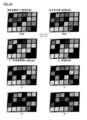
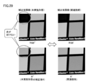
(F6: correction result according to the first embodiment)
FIG. 28 shows an example of a correction result obtained by the image processing method according to the first embodiment of the present invention. FIG. 29 is an enlarged view of the correction result shown in FIG.
図28および図29に示すように、関連技術による画像処理方法では、ぼけが生じてしまっていた部分(負相関をもつ赤のパッチ部)について、本実施の形態に従う画像処理方法では、ぼけの発生を防止できる。すなわち、本実施の形態に従う画像処理方法では、補正に問題が生じる領域(負相関をもつ領域)については、誤ってぼかしてしまわないように、補正内容を修正できていることがわかる。
As shown in FIG. 28 and FIG. 29, in the image processing method according to the related art, in the image processing method according to the present embodiment, the blur (red patch portion having a negative correlation) that has been blurred is generated. Occurrence can be prevented. In other words, in the image processing method according to the present embodiment, it can be seen that the correction content can be corrected so as not to blur the region that has a problem in correction (region having negative correlation).
上述の説明では、説明の便宜上、複数の色を有する複数のパッチ部(人工物)を被写体とした入力画像に本実施の形態に従う画像処理方法を提供した例を示したが、通常の被写体を写した自然な入力画像に対しても、同様の効果が得られる。
In the above description, for the sake of convenience of explanation, an example in which the image processing method according to the present embodiment is provided for an input image having a plurality of patch portions (artifacts) having a plurality of colors as subjects is shown. A similar effect can be obtained for a natural input image that has been copied.
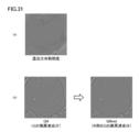
図30および図31は、本発明の実施の形態1に従う画像処理方法による補正結果の別の例を示す図である。
30 and 31 are diagrams showing another example of the correction result by the image processing method according to the first embodiment of the present invention.
図30において、(a)は、処理対象の入力画像を示し、(b)は、関連技術に従う画像処理方法によって得られる補正後画像を示し、(c)は、本実施の形態に従う画像処理方法によって得られる補正後画像を示す。
30A shows an input image to be processed, FIG. 30B shows a corrected image obtained by an image processing method according to the related art, and FIG. 30C shows an image processing method according to the present embodiment. The corrected image obtained by is shown.
図30(b)に示すように、関連技術に従う画像処理方法では、服の端部や襟の部分において、誤った補正がなされていたが、図30(c)に示すように、本実施の形態に従う画像処理方法では、このような誤った補正が生じないように処理がなされていることがわかる。
As shown in FIG. 30 (b), in the image processing method according to the related art, erroneous correction was made at the end of the clothes and the collar, but as shown in FIG. It can be seen that in the image processing method according to the embodiment, processing is performed so that such erroneous correction does not occur.
より具体的には、図31(a)に示すような濃淡方向相関度を算出するとともに、図31(b)に示すように、この算出された濃淡方向相関度に基づいて、入力画像のGの高周波成分(GH)を補正することで、入力画像のRを補正するためのGの高周波成分(GHred)が適切に算出される。
More specifically, the gray level correlation degree as shown in FIG. 31 (a) is calculated, and as shown in FIG. 31 (b), the G of the input image is calculated based on the calculated gray direction correlation degree. By correcting the high frequency component (GH), the G high frequency component (GHred) for correcting the R of the input image is appropriately calculated.
(f7:変形例)
上述の説明においては、入力画像のRについて、濃淡方向相関度を算出するとともに、当該算出した濃淡方向相関度に基づいて入力画像のRを補正するためのGの高周波成分(GHred)を算出した上で、入力画像のRを補正する例を記載した。これに代えて、あるいは、これに代えて、入力画像のBに対しても同様の画像処理方法を適用できることは自明である。この場合においても、同様の効果が得られることも自明である。
(F7: Modification)
In the above description, the gray level correlation degree is calculated for R of the input image, and the high frequency component (GHred) of G for correcting the R of the input image is calculated based on the calculated gray level correlation degree. In the above, the example which correct | amends R of an input image was described. It is obvious that the same image processing method can be applied to B of the input image instead of this or instead of this. Also in this case, it is obvious that the same effect can be obtained.
上述の実施の形態1においては、入力画像のGの高周波成分(GH)を入力画像のY(輝度)へ移植する処理例について記載したが、RGB色空間やYCrCb色空間といった異なる色空間の間で、高周波成分を移植する処理においても同様の効果を得ることができる。例えば、上述の特開2007-028041号公報(特許文献1)に開示されるように、入力画像のRおよび/またはBに対して、Gの高周波成分を直接的に加算するという処理例を採用した場合であって、本実施の形態に従う画像処理方法を同様に適用でき、かつ同様の効果を奏する。
In the above-described first embodiment, the processing example in which the high frequency component (GH) of G of the input image is transplanted to Y (luminance) of the input image has been described, but between different color spaces such as the RGB color space and the YCrCb color space. Thus, the same effect can be obtained in the process of transplanting the high frequency component. For example, as disclosed in the above-mentioned Japanese Patent Application Laid-Open No. 2007-028041 (Patent Document 1), a processing example in which a high frequency component of G is directly added to R and / or B of an input image is adopted. In this case, the image processing method according to the present embodiment can be applied in the same manner and has the same effect.
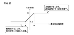
補正係数cについては、負相関の部分については補正を全く止めるのではなく、補正度合いを弱めるだけでもよい。図32は、本発明の実施の形態1の変形例に従う補正用の高周波成分を算出するための補正係数の一例を示す図である。図32に示す補正係数cでは、負相関のところはGの高周波成分の補正度合いを弱めるために、濃淡方向相関度が-αを下回る場合には、一例として補正係数c=0.2を採用する。この負相関における補正係数cは、0から1.0の範囲にあるいずれかの値を採用し得る。
As for the correction coefficient c, correction of the negative correlation portion may not be stopped at all, but only the degree of correction may be weakened. FIG. 32 is a diagram showing an example of a correction coefficient for calculating a high frequency component for correction according to the modification of the first embodiment of the present invention. In the correction coefficient c shown in FIG. 32, in the case of a negative correlation, the correction coefficient c = 0.2 is adopted as an example when the degree of correlation in the light and dark direction is less than −α in order to weaken the correction degree of the high frequency component of G. To do. As the correction coefficient c in this negative correlation, any value in the range of 0 to 1.0 can be adopted.
このように、本実施の形態に従う画像処理装置は、負相関の領域に対して、高周波成分を加算しない、または弱める。すなわち、本実施の形態に従う画像処理装置は、注目領域についての濃淡方向相関度が、第1の色成分と第2の色成分の濃淡方向が同一方向である正相関を示すときに、補正対象の色成分に対して高周波成分を加算する一方で、注目領域についての濃淡方向相関度が、第1の色成分と第2の色成分の濃淡方向が逆方向である負相関を示すときに、正相関の場合と比較して低減された第1の色成分の高周波成分を補正対象の色成分に対して加算する高周波成分の大きさを正相関の場合に比較して低減する。
As described above, the image processing apparatus according to the present embodiment does not add or weaken the high frequency component to the negative correlation region. In other words, the image processing apparatus according to the present embodiment corrects when the degree of contrast in the light and shade direction for the attention area indicates a positive correlation in which the light and shade directions of the first color component and the second color component are in the same direction. When the high-frequency component is added to the color component of the color area, while the shade direction correlation degree for the attention area indicates a negative correlation in which the shade direction of the first color component and the second color component is opposite, The magnitude of the high frequency component for adding the high frequency component of the first color component, which is reduced compared to the case of the positive correlation, to the color component to be corrected is reduced as compared with the case of the positive correlation.
(f8:利点)
光学系の軸上色収差などにより入力画像がぼけを含む場合、最もMTF特性の良い色(例えば、G)の高周波成分を、他の色(例えば、R)の高周波成分に単純に移植(加算)することで、このようなぼけを補正しようとすると、一部の領域で逆にぼけたり、エッジに不自然な画像処理がかかったりすることがある。これに対して、本実施の形態においては、色毎に濃淡変化の方向が同じであるか否か、すなわち濃淡方向相関度を評価することで、このような他の色の高周波成分に移植(加算)してよいか否かを判断することで、ぼけの発生といった副作用が生じないように、画像補正を行なうことができる。
(F8: Advantage)
When the input image contains blur due to axial chromatic aberration of the optical system, the high frequency component of the color having the best MTF characteristic (for example, G) is simply transplanted (added) to the high frequency component of another color (for example, R). Thus, when trying to correct such a blur, a part of the region may be blurred in reverse, or an unnatural image processing may be applied to the edge. On the other hand, in the present embodiment, whether or not the direction of the change in shade is the same for each color, that is, by evaluating the degree of correlation in the shade direction, it is transplanted to the high-frequency components of such other colors ( By determining whether or not to add, it is possible to perform image correction so that side effects such as blurring do not occur.
<G.実施の形態2>
上述の実施の形態1においては、濃淡方向相関度が負相関の場合に、高周波成分を加算しない、または弱める処理例について説明した。これに対して、実施の形態2においては、濃淡方向相関度が負相関の場合に、高周波成分を減算する処理例について説明する。
<G. Second Embodiment>
In the above-described first embodiment, the processing example in which the high frequency component is not added or weakened when the grayscale direction correlation degree is negative correlation has been described. On the other hand, in the second embodiment, an example of processing for subtracting a high-frequency component when the grayscale direction correlation degree is negative correlation will be described.
実施の形態2に従う画像処理方法は、図18に示す実施の形態1に従う画像処理方法の手順を示すフローチャートに比較して、基準となる色成分(典型的には、G)についての高周波成分から補正値を算出する処理(ステップS5)の処理内容が異なっているだけであるので、それ以外の処理の詳細な説明は繰り返さない。以下、主として、実施の形態1との相違点について説明する。
Compared with the flowchart showing the procedure of the image processing method according to the first embodiment shown in FIG. 18, the image processing method according to the second embodiment is based on the high-frequency component for the reference color component (typically G). Since only the processing content of the processing for calculating the correction value (step S5) is different, detailed description of the other processing will not be repeated. Hereinafter, differences from the first embodiment will be mainly described.
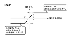
図33は、本発明の実施の形態2に従う補正用の高周波成分を算出するための処理を示す図である。図34は、本発明の実施の形態2に従う補正用の高周波成分を算出するための補正係数の一例を示す図である。
FIG. 33 is a diagram showing processing for calculating a high-frequency component for correction according to the second embodiment of the present invention. FIG. 34 shows an example of a correction coefficient for calculating a high frequency component for correction according to the second embodiment of the present invention.
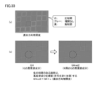
図33(a)に示すような濃淡方向相関度が算出されると、この算出された濃淡方向相関度を用いて、入力画像のRを補正するためのGの高周波成分(GHred2)が算出される。より具体的には、図33(b)に示すような入力画像のGの高周波成分(GH)のうち、正相関を有する部分では高周波成分を残し、負相関を有する部分では高周波成分を減算するような、入力画像のRを補正するためのGの高周波成分(GHred2)を生成する。このGの高周波成分(GHred)の生成には、図34に示すような補正係数cを用いる。
When the gray level correlation degree as shown in FIG. 33A is calculated, a G high frequency component (GHred2) for correcting R of the input image is calculated using the calculated gray level correlation degree. The More specifically, among the high-frequency components (GH) of the G of the input image as shown in FIG. 33 (b), the high-frequency component is left in the portion having the positive correlation, and the high-frequency component is subtracted in the portion having the negative correlation. Such a high frequency component (GHred2) of G for correcting the R of the input image is generated. For the generation of the G high frequency component (GHred), a correction coefficient c as shown in FIG. 34 is used.
図34に示す補正係数cに関して、正相関のところはGの高周波成分をそのまま残すために、濃淡方向相関度がαを超える場合には、補正係数c=1を採用する。一方、負相関のところはGの高周波成分を減算(符号を逆にして加算)するために、濃淡方向相関度が-αを下回る場合には、補正係数c=-1を採用する。正相関と負相関との間で急激な変化を避けるために、濃淡方向相関度が-αからαの範囲にある場合には、補正係数を濃淡方向相関度についての一次関数に設定して、補正係数の変化を滑らかにしている。
34, with respect to the correction coefficient c shown in FIG. 34, the high-frequency component of G remains as it is at the positive correlation, and therefore the correction coefficient c = 1 is employed when the degree of correlation in the light and dark direction exceeds α. On the other hand, in the case of negative correlation, since the high frequency component of G is subtracted (added with the sign reversed), the correction coefficient c = −1 is adopted when the light / dark direction correlation is less than −α. To avoid a sharp change between positive and negative correlations, if the gray level correlation is in the range of -α to α, the correction coefficient is set to a linear function for the gray level correlation, The change of the correction coefficient is made smooth.
このような補正係数cを用いて入力画像のRを補正するためのGの高周波成分(GHred2)を生成することで、Yに対して負相関のところでは、関連技術に従う画像処理方法とは逆向きにエッジが立つことになる。
By generating a high-frequency component (GHred2) of G for correcting R of the input image using such a correction coefficient c, a negative correlation with respect to Y is opposite to the image processing method according to the related art. Edges will stand in the direction.
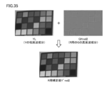
図35は、本発明の実施の形態2に従う画像処理方法における入力画像の補正処理を説明するための図である。図36は、図35に示す入力画像の補正処理による補正の効果を説明するための図である。図37は、本発明の実施の形態2に従う画像処理方法による補正結果の一例を示す図である。
FIG. 35 is a diagram for describing input image correction processing in the image processing method according to the second embodiment of the present invention. FIG. 36 is a diagram for explaining the effect of correction by the input image correction processing shown in FIG. FIG. 37 shows an example of a correction result obtained by the image processing method according to the second embodiment of the present invention.
図35を参照して、入力画像のRを補正するためのGの高周波成分(GHred2)が入力画像のRの輝度(Y’red)へ移植される。すなわち、入力画像のRについては、Gの高周波成分(GHred2)を用いて、R用の補正後の輝度(Y’red2)が算出される。より具体的には、入力画像の輝度の低周波成分(YL)にGの高周波成分(GHred2)が加算されることで、輝度(Y’red2)が算出される。
Referring to FIG. 35, the high frequency component of G (GHred2) for correcting R of the input image is transplanted to the luminance (Y′red) of R of the input image. That is, for R of the input image, the corrected luminance (Y′red2) for R is calculated using the high-frequency component of G (GHred2). More specifically, the luminance (Y′red2) is calculated by adding the high frequency component (GHred2) of G to the low frequency component (YL) of the luminance of the input image.
図36に示すように、このような補正方法を採用することで、図15に示すような負相関が原因でぼけが発生していた赤のパッチ部のエッジに対しては、図15に示す例とは逆向きにエッジが補正される。これによって、図37に示すように、赤のパッチ部をよりシャープになるように補正することが可能になる。
As shown in FIG. 36, by adopting such a correction method, the edge of the red patch portion where the blur has occurred due to the negative correlation as shown in FIG. 15 is shown in FIG. Edges are corrected in the opposite direction to the example. As a result, as shown in FIG. 37, the red patch portion can be corrected to be sharper.
このように、本実施の形態に従う画像処理装置は、負相関の領域に対して、高周波成分を減算する。すなわち、本実施の形態に従う画像処理装置は、注目領域についての濃淡方向相関度が、第1の色成分と第2の色成分の濃淡方向が同一方向である正相関を示すときに、補正対象の色成分に対して第1の色成分の高周波成分を加算する一方で、注目領域についての濃淡方向相関度が、第1の色成分と第2の色成分の濃淡方向が逆方向である負相関を示すときに、補正対象の色成分に対して第1の色成分の高周波成分を減算する。
Thus, the image processing apparatus according to the present embodiment subtracts the high frequency component from the negative correlation area. In other words, the image processing apparatus according to the present embodiment corrects when the degree of contrast in the light and shade direction for the attention area indicates a positive correlation in which the light and shade directions of the first color component and the second color component are in the same direction. While the high-frequency component of the first color component is added to the color component of the first color component, the correlation in the grayscale direction for the region of interest is negative in which the grayscale directions of the first color component and the second color component are opposite. When showing the correlation, the high frequency component of the first color component is subtracted from the color component to be corrected.
本実施の形態においては、色毎に濃淡変化の方向が同じであるか否か、すなわち濃淡方向相関度を評価することで、このような他の色の高周波成分に加算すべきか、減算すべきかを判断することで、ぼけの発生といった副作用が生じないように、画像補正を行なうことができる。
In the present embodiment, whether or not the direction of the light and shade change is the same for each color, that is, whether or not to add to or subtract from the high frequency components of such other colors by evaluating the light and shade direction correlation degree. By judging the above, it is possible to perform image correction so that side effects such as blurring do not occur.
<H.実施の形態3>
上述の実施の形態1および2においては、画像全体に対して、濃淡方向相関度が負相関であるか否かに応じて、高周波成分を用いた補正方法を変更する(高周波成分を加算しない、弱める、逆に加算する)処理例について説明した。
<H. Embodiment 3>
In the first and second embodiments described above, the correction method using the high-frequency component is changed (not adding the high-frequency component, depending on whether or not the gray-scale direction correlation is a negative correlation for the entire image. A processing example of weakening and adding in reverse has been described.
しかしながら、実際には空間周波数が高い画像領域(典型的には、ごちゃごちゃした画像領域)では、エッジの濃淡変化方向が意図したものと異なっていても、そのままエッジを立てた方が、画像として見栄えよく補正できる場合もある。そこで、実施の形態3においては、高周波成分が少ない画像領域についてのみ、濃淡方向相関度に依存して補正方法を変更する処理例について説明する。
However, in reality, in an image region with a high spatial frequency (typically a messed up image region), it is better to stand the edge as it is, even if the direction of change in the shade of the edge is different from the intended one. In some cases, it can be corrected well. Therefore, in the third embodiment, a description will be given of a processing example in which the correction method is changed only for an image region having a small number of high frequency components, depending on the light / dark direction correlation degree.
本実施の形態に従う画像処理方法では、まず、処理対象の入力画像を複数の部分領域に区分するとともに、各部分領域について、高周波成分が多い領域であるか、あるいは少ない領域であるかを判断する。そして、高周波成分が多い領域については、上述した関連技術に従う画像処理方法を適用し、濃淡方向相関度とは無関係に、入力画像の高周波成分を用いて補正を行なう。これに対して、高周波成分が少ない領域については、上述した実施の形態1または2に従う画像処理方法を適用し、濃淡方向相関度に依存して、高周波成分を用いた補正方法を変更する。
In the image processing method according to the present embodiment, first, an input image to be processed is divided into a plurality of partial areas, and it is determined whether each partial area is an area with a high frequency component or a low area. . Then, for a region having a high frequency component, the image processing method according to the related art described above is applied, and correction is performed using the high frequency component of the input image regardless of the grayscale direction correlation degree. On the other hand, the image processing method according to the first or second embodiment described above is applied to a region with a small amount of high-frequency components, and the correction method using the high-frequency components is changed depending on the density direction correlation.
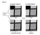
図38は、本発明の実施の形態3に従う画像処理方法の概要を説明するための図である。図39は、本発明の実施の形態3に従う画像処理方法において使用される補正係数の一例を示す図である。
FIG. 38 is a diagram for describing the outline of the image processing method according to the third embodiment of the present invention. FIG. 39 shows an example of the correction coefficient used in the image processing method according to the third embodiment of the present invention.
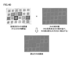
図38を参照して、画像処理装置1は、まず、入力画像を複数の部分領域(赤点線の領域)に分割する。各部分領域は、例えば50画素×50画素のサイズに設定される。続いて、画像処理装置1は、部分領域毎に、高周波成分が多い領域であるか、高周波成分が少ない領域であるかを判定する。そして、画像処理装置1は、高周波成分が多い領域については、図5に示す関連技術に従う画像処理方法を適用し、高周波成分が少ない領域については、上述の実施の形態1または2に従う画像処理方法を適用する。すなわち、画像処理装置1は、高周波成分が少ない領域に対してのみ、濃淡方向相関度に応じて高周波成分の処理を変更する(高周波成分を加算しない、弱める、逆に加算する)。
38, the image processing apparatus 1 first divides the input image into a plurality of partial areas (red dotted line areas). Each partial area is set to a size of 50 pixels × 50 pixels, for example. Subsequently, the image processing apparatus 1 determines, for each partial region, whether the region has a high frequency component or a region with a low high frequency component. Then, the image processing apparatus 1 applies the image processing method according to the related technique shown in FIG. 5 to a region having a high frequency component, and applies the image processing method according to the above-described first or second embodiment to a region having a low high frequency component. Apply. That is, the image processing apparatus 1 changes the processing of the high-frequency component only for the region where the high-frequency component is small according to the contrast direction in the light / dark direction (does not add, weaken, or add the high-frequency component).
言い換えれば、画像処理装置1は、入力画像のうち高周波成分が少ない領域については、図39(a)または図39(b)に示す補正係数cを用いて補正を行ない、入力画像のうち高周波成分が多い領域については、図39(c)に示す補正係数cを用いて補正を行なう。この図39(c)に示す補正係数cは、濃淡方向相関度に依存することなく常に「1」となっている。
In other words, the image processing apparatus 1 performs correction using the correction coefficient c shown in FIG. 39 (a) or 39 (b) for a region with a low high-frequency component in the input image, and the high-frequency component in the input image. For regions with a large amount of correction, correction is performed using the correction coefficient c shown in FIG. The correction coefficient c shown in FIG. 39 (c) is always “1” without depending on the light / dark direction correlation degree.
入力画像に設定される部分領域の高周波成分が多いのか、あるいは少ないのかという判断は、例えば、上述の実施の形態1または2において説明したように、入力画像のRを補正する場合には、Rの高周波成分(RH)の絶対値がしきい値(例えば、10)以上であるか否かに基づいて判断すればよい。この判断方法によれば、Rの高周波成分(RH)の絶対値がしきい値以上である領域をRの高周波領域と判定し、部分領域に占める高周波領域の割合が一定値以下の場合(例えば、50%以下)なら、高周波成分が少ない領域と判定する。これに対して、部分領域に占める高周波領域の割合が当該一定値を超えている場合(例えば、50%超)なら、高周波成分が多い領域と判定する。
For example, when the R of the input image is corrected as described in the first or second embodiment, the determination as to whether the high-frequency component in the partial region set in the input image is large or small can be made. It may be determined based on whether or not the absolute value of the high-frequency component (RH) is greater than or equal to a threshold value (for example, 10). According to this determination method, a region in which the absolute value of the R high-frequency component (RH) is greater than or equal to the threshold value is determined as the R high-frequency region, and the ratio of the high-frequency region to the partial region is equal to or less than a certain value (for example, , 50% or less), it is determined that the region has few high-frequency components. On the other hand, if the ratio of the high frequency region to the partial region exceeds the certain value (for example, more than 50%), it is determined that the region has a high frequency component.
このように、本実施の形態に従う画像処理装置は、注目領域に高周波成分が多く含まれているか否かを判断し、注目領域に高周波成分が多く含まれていない場合には、濃淡方向相関度に応じた方法で注目領域についての第2の色成分を補正する一方、注目領域に高周波成分が多く含まれている場合には、濃淡方向相関度に依存せず、予め定められた方法で注目領域についての補正対象の色成分を補正する。すなわち、負相関を有する領域であって、かつ低周波領域(高周波成分が少ない領域)についてのみ、高周波成分による補正方法を変更(加算しない/弱める/減算する)する。
As described above, the image processing apparatus according to the present embodiment determines whether or not the attention area includes a lot of high-frequency components. When the second color component for the region of interest is corrected by a method according to the above, and when the region of interest contains a lot of high-frequency components, the region of interest is determined by a predetermined method without depending on the shade direction correlation degree. The color component to be corrected for the region is corrected. That is, the correction method using the high-frequency component is changed (not added / weakened / subtracted) only in a region having a negative correlation and in a low-frequency region (a region having a low high-frequency component).
本実施の形態においては、濃淡方向相関度に応じた補正を適用するか否かを判断した上で、関連技術に従う画像処理方法を適用して一律にエッジを強調するのか、濃淡方向相関度に依存させて高周波成分の適用方法を変更するのかを切り替える。これによって、処理を高速化できるとともに、画像全体としてより自然な補正を行なうことができる。
In this embodiment, after determining whether or not to apply correction according to the gray-scale direction correlation degree, whether to apply an image processing method according to the related technology to uniformly enhance the edge, or to the gray-scale direction correlation degree Switch depending on whether to change the application method of high frequency components. As a result, the processing can be speeded up, and more natural correction can be performed for the entire image.
<I.実施の形態4>
上述の実施の形態1~3においては、濃淡方向相関度の算出にNCC法を用いる例について説明したが、これ以外の方法を用いて濃淡方向相関度を算出することもできる。
<I. Embodiment 4>
In the first to third embodiments described above, the example in which the NCC method is used to calculate the light / dark direction correlation degree has been described. However, the light / dark direction correlation degree can also be calculated using other methods.
すなわち、上述の(1)式では、NCC法を用いて濃淡方向相関度を算出したが、以下の(4)式に従って、高周波成分の相関値(RHとGHとの相関値)を算出してもよい。この(4)式は、平方根演算を含まないので、演算処理を高速化できる。
That is, in the above-described equation (1), the light / dark direction correlation degree is calculated using the NCC method, but according to the following equation (4), the correlation value of the high frequency component (correlation value between RH and GH) is calculated. Also good. Since this equation (4) does not include the square root calculation, the calculation process can be speeded up.
この(4)式によって得られる結果に、実施の形態1と同様に、以下の(5)式に従って、RHの絶対値(Rのエッジであるかどうか(濃淡変化が大きいか)の情報)を掛け合わせることで、濃淡方向相関度を算出する。
In the same way as in the first embodiment, the absolute value of RH (information on whether it is an edge of R (whether the change in shading is large)) is obtained from the result obtained by the expression (4) according to the following expression (5), as in the first embodiment. The shade direction correlation degree is calculated by multiplying.
濃淡方向相関度=高周波成分の相関値×|RH| …(5)
図40は、本発明の実施の形態4に従う画像処理方法における濃淡方向相関度の算出結果の一例を示す図である。図40に示すように、NCC法を用いて算出した濃淡方向相関度(図22参照)と同様の結果が得られることがわかる。
Correlation between light and dark directions = correlation value of high frequency component × | RH | (5)
FIG. 40 is a diagram showing an example of the calculation result of the light / dark direction correlation degree in the image processing method according to the fourth embodiment of the present invention. As shown in FIG. 40, it can be seen that the same result as the grayscale correlation (see FIG. 22) calculated using the NCC method is obtained.
上述のように、濃淡方向相関度を算出する際に利用する「高周波成分の相関値」の算出方法としては、NCC法に限定されるものではなく、エッジの濃淡変化方向が同じ場合と逆である場合との間で、符号が逆転するような相関値を計算できれば、他のどのような方法または処理であっても採用できる。
As described above, the method of calculating the “correlation value of the high frequency component” used when calculating the density direction correlation is not limited to the NCC method, and is opposite to the case where the edge density change direction is the same. Any other method or process can be adopted as long as a correlation value that reverses the sign between the cases can be calculated.
<J.利点>
本発明の実施の形態によれば、光学系の軸上色収差などにより入力画像がぼけを含む場合、最もMTF特性の良い色(例えば、G)の高周波成分を、他の色(例えば、R)の高周波成分に単純に移植(加算)することで、このようなぼけを補正しようとすると、一部の領域で逆にぼけたり、エッジに不自然な画像処理がかかったりすることがある。これに対して、本実施の形態によれば、より自然なかたちでぼけを補正できる。
<J. Advantage>
According to the embodiment of the present invention, when the input image includes blur due to axial chromatic aberration of the optical system, the high frequency component of the color having the best MTF characteristic (for example, G) is changed to another color (for example, R). If such blurring is corrected by simply transplanting (adding) to the high-frequency component, it may be blurred in some areas or unnatural image processing may be applied to the edges. On the other hand, according to the present embodiment, blur can be corrected in a more natural manner.
また、このようなぼけを有効に補正できるため、MTF特性を必ずしも良好にしなくとも、被写体を写したより自然な入力画像を取得できる。これによって、デジタルカメラなどに実装した場合には、レンズの光学特性を過度に高める必要がなく、装置全体の簡素化やコスト低減を実現し得る。
In addition, since such blur can be effectively corrected, a more natural input image showing the subject can be acquired without necessarily improving the MTF characteristics. As a result, when mounted on a digital camera or the like, it is not necessary to excessively improve the optical characteristics of the lens, and the entire apparatus can be simplified and the cost can be reduced.
今回開示された実施の形態はすべての点で例示であって制限的なものではないと考えられるべきである。本発明の範囲は上記した説明ではなくて請求の範囲によって示され、請求の範囲と均等の意味および範囲内でのすべての変更が含まれることが意図される。
The embodiment disclosed this time should be considered as illustrative in all points and not restrictive. The scope of the present invention is defined by the terms of the claims, rather than the description above, and is intended to include any modifications within the scope and meaning equivalent to the terms of the claims.