JP5235642B2 - Image processing apparatus and method - Google Patents
Image processing apparatus and method Download PDFInfo
- Publication number
- JP5235642B2 JP5235642B2 JP2008318937A JP2008318937A JP5235642B2 JP 5235642 B2 JP5235642 B2 JP 5235642B2 JP 2008318937 A JP2008318937 A JP 2008318937A JP 2008318937 A JP2008318937 A JP 2008318937A JP 5235642 B2 JP5235642 B2 JP 5235642B2
- Authority
- JP
- Japan
- Prior art keywords
- image
- blur correction
- optical system
- imaging optical
- image processing
- Prior art date
- Legal status (The legal status is an assumption and is not a legal conclusion. Google has not performed a legal analysis and makes no representation as to the accuracy of the status listed.)
- Active
Links
Images


Classifications
-
- H—ELECTRICITY
- H04—ELECTRIC COMMUNICATION TECHNIQUE
- H04N—PICTORIAL COMMUNICATION, e.g. TELEVISION
- H04N23/00—Cameras or camera modules comprising electronic image sensors; Control thereof
- H04N23/80—Camera processing pipelines; Components thereof
-
- H—ELECTRICITY
- H04—ELECTRIC COMMUNICATION TECHNIQUE
- H04N—PICTORIAL COMMUNICATION, e.g. TELEVISION
- H04N25/00—Circuitry of solid-state image sensors [SSIS]; Control thereof
- H04N25/60—Noise processing, e.g. detecting, correcting, reducing or removing noise
- H04N25/61—Noise processing, e.g. detecting, correcting, reducing or removing noise the noise originating only from the lens unit, e.g. flare, shading, vignetting or "cos4"
- H04N25/615—Noise processing, e.g. detecting, correcting, reducing or removing noise the noise originating only from the lens unit, e.g. flare, shading, vignetting or "cos4" involving a transfer function modelling the optical system, e.g. optical transfer function [OTF], phase transfer function [PhTF] or modulation transfer function [MTF]
-
- H—ELECTRICITY
- H04—ELECTRIC COMMUNICATION TECHNIQUE
- H04N—PICTORIAL COMMUNICATION, e.g. TELEVISION
- H04N23/00—Cameras or camera modules comprising electronic image sensors; Control thereof
- H04N23/80—Camera processing pipelines; Components thereof
- H04N23/84—Camera processing pipelines; Components thereof for processing colour signals
- H04N23/843—Demosaicing, e.g. interpolating colour pixel values
Description
本発明は、撮像光学系による画像の暈けを補正する画像処理に関する。 The present invention relates to image processing for correcting image blurring by an imaging optical system.
ディジタルカメラ、ディジタルビデオカメラなどの撮像装置は、被写体からの光を、レンズなどで構成される撮像光学系によって、撮像デバイスであるCCDやCMOSセンサ上に導き、結像させる。撮像デバイスは、受光した光を電気信号に変換する。この電気信号に、アナログ-ディジタル(A/D)変換やデモザイキングなど電気信号を画像化するための処理を施して、撮影画像を得る。 An imaging apparatus such as a digital camera or a digital video camera guides light from a subject onto a CCD or CMOS sensor, which is an imaging device, by an imaging optical system including a lens or the like to form an image. The imaging device converts the received light into an electrical signal. The electrical signal is subjected to processing for imaging the electrical signal, such as analog-digital (A / D) conversion and demosaicing, to obtain a photographed image.
撮像デバイスに到達する光は撮像光学系を通過するため、撮影画像の画質は撮像光学系の影響を受ける。例えば、高性能なレンズを使用すれば、画像の周辺領域に至るまで解像度の高い撮影画像を得ることができる。逆に、安価な低性能のレンズを使用すれば、撮影画像の、とくに周辺領域の解像度の低下が著しい。 Since the light reaching the imaging device passes through the imaging optical system, the image quality of the captured image is affected by the imaging optical system. For example, if a high-performance lens is used, a captured image with high resolution can be obtained up to the peripheral region of the image. On the contrary, if an inexpensive low-performance lens is used, the resolution of the captured image, particularly in the peripheral area, is significantly reduced.
例えば、星空を撮影する場合、高性能レンズで撮影した画像は一つひとつの星がほぼ点像になる。低性能レンズで撮影した画像の星は点像にならず暈ける。また、人物を撮影する場合、高性能レンズを用いれば一本一本の髪の毛が記録された画像を得ることができるが、低性能レンズを用いれば髪の毛が暈けた画像が得られる。つまり、低性能レンズを使うと精細感に欠ける画像になる。 For example, when shooting a starry sky, each star captured by a high-performance lens is almost a point image. Stars in images taken with a low-performance lens are not point images and can be gained. When a person is photographed, an image in which each hair is recorded can be obtained by using a high-performance lens, but an image in which the hair is lost can be obtained by using a low-performance lens. In other words, using a low-performance lens results in an image lacking in fineness.
このような暈けはピントが合っていても発生する、撮像光学系の特性に依存した暈けである。言い換えれば、ピントが合っていてもレンズの性能により撮影画像の解像度に違いが生じる。 Such a blur is generated depending on the characteristics of the imaging optical system, which occurs even when focus is achieved. In other words, even if the image is in focus, the resolution of the captured image varies depending on the performance of the lens.
撮影画像に画像処理を施して、撮像光学系に起因する画像の暈けを補正する方法がある。この方法は、予めデータ化した撮像光学系の暈けの特性に基づき画像処理を行い、撮像光学系に起因する画像の暈けを補正する。 There is a method of correcting image blur caused by an imaging optical system by performing image processing on a captured image. This method performs image processing based on the blur characteristics of the imaging optical system that has been converted into data in advance, and corrects blurring of the image caused by the imaging optical system.
撮像光学系の暈けの特性をデータ化するには、例えば、点像分布関数(point spread function: PSF)を用いる方法がある。PSFは、被写体の一点がどのように暈けるかを表す。例えば、暗黒下において、体積が非常に小さい発光体(点光源)を撮像光学系を介して撮影した場合、理想的な撮像光学系を用いれば撮像デバイスの面(撮像面)上に結像する光は点になる。しかし、暈けが大きい撮像光学系を用いれば撮像面上に結像する光は点にはならず、ある程度の広がりをもつ。つまり、撮像面上における光の二次元分布が当該撮像光学系のPSFに相当する。実際に撮像光学系のPSFを取得する場合、必ずしも、点光源のような被写体を撮影する必要はない。例えば、白と黒のエッジを有するチャートを撮影した画像から、チャートに対応した計算方法によってPSFを計算することができる。 In order to convert the blur characteristics of the imaging optical system into data, for example, there is a method using a point spread function (PSF). PSF represents how one point of a subject can make money. For example, when a light emitting body (point light source) having a very small volume is photographed via an imaging optical system in the dark, an image is formed on the surface (imaging surface) of the imaging device using an ideal imaging optical system. Light becomes a spot. However, if an imaging optical system with a large blur is used, the light that forms an image on the imaging surface does not become a point but has a certain extent. That is, the two-dimensional light distribution on the imaging surface corresponds to the PSF of the imaging optical system. When actually obtaining the PSF of the imaging optical system, it is not always necessary to photograph a subject such as a point light source. For example, PSF can be calculated from an image obtained by photographing a chart having white and black edges by a calculation method corresponding to the chart.
PSFによって画像の暈けを補正する方法として、逆フィルタを用いる方法が知られている(特許文献1)。説明のため暗黒下で点光源を撮影する場合を想定する。暈けがある撮像光学系を用いれば、点光源から出た光は、撮像面上に、ある程度の広がりを有する光の分布を形成する。光は撮像デバイスによって電気信号になる。この電気信号を画像化すると点光源を撮影したディジタル画像が得られる。暈けがある撮像光学系を用いて撮影した画像は、点光源に対応する一画素だけが零ではない有意の画素値を有するわけではなく、その周辺の画素も零に近いが有意の画素値を有する。この画像を、ほぼ一点で有意な画素値をもつ画像に変換する画像処理が逆フィルタである。逆フィルタによって、恰も暈けが少ない撮像光学系で撮影したような画像が得られる。 As a method for correcting image blur using PSF, a method using an inverse filter is known (Patent Document 1). For the sake of explanation, it is assumed that a point light source is photographed in the dark. If a blurred imaging optical system is used, the light emitted from the point light source forms a light distribution having a certain extent on the imaging surface. The light becomes an electrical signal by the imaging device. When this electrical signal is imaged, a digital image obtained by photographing a point light source is obtained. An image taken using a blurry imaging optical system does not have a significant pixel value that is not zero only for one pixel corresponding to a point light source, and the neighboring pixels are also close to zero but have a significant pixel value. Have. Image processing for converting this image into an image having a significant pixel value at almost one point is an inverse filter. With the inverse filter, an image as if taken with an imaging optical system with little blur was obtained.
上記では、説明のために点光源を例にしたが、被写体からの光も多数の点光源の集まりと考えれば、被写体の各部から放出または各部が反射する光のそれぞれの暈けをなくして、点光源以外の被写体についても暈けが少ない画像が得られる。 In the above, a point light source is taken as an example for explanation, but if light from the subject is also considered as a collection of many point light sources, each of the light emitted from each part of the subject or reflected by each part is eliminated, An image with less blur can be obtained for subjects other than point light sources.
次に、逆フィルタの具体的な構成方法を説明する。ここで、暈けがない理想的な撮像光学系を用いて撮影した撮影画像をf(x, y)とする。x、yは、画像の二次元上の画素位置を示し、f(x, y)は画素(x, y)の画素値を表す。一方、暈けがある撮像光学系で撮影した撮影画像をg(x, y)とする。また、暈けがある撮像光学系のPSFをh(x, y)で表す。するとf、g、hには次の関係がなり立つ。
g(x, y) = h(x, y)*f(x, y) …(1)
ここで、*はコンボリューションを表す。
Next, a specific configuration method of the inverse filter will be described. Here, a photographed image photographed using an ideal imaging optical system without any blur is assumed to be f (x, y). x and y indicate two-dimensional pixel positions of the image, and f (x, y) indicates the pixel value of the pixel (x, y). On the other hand, let g (x, y) be a photographed image taken with an imaging optical system with blur. Further, the PSF of the imaging optical system having a blur is represented by h (x, y). Then f, g and h have the following relationship.
g (x, y) = h (x, y) * f (x, y)… (1)
Here, * represents convolution.
画像の暈けの補正(以下、暈け補正)は、暈けがある撮像光学系を用いて撮影した画像gと、当該撮像光学系のPSFであるhから、暈けがない撮像光学系で撮影されるfを推定すること、と言い換えることができる。また、上式をフーリエ変換により空間周波数における表示形式にすると、下式のように周波数ごとの積の形式になる。
G(u, v) = H(u, v)・F(u, v) …(2)
ここで、HはPSFのフーリエ変換である光学伝達関数(optical transfer function: OTF)、
uはx方向の空間周波数、
vはy方向の空間周波数、
Gはgのフーリエ変換、
Fはfのフーリエ変換。
Image blur correction (hereinafter referred to as blur correction) is taken with an imaging optical system that does not produce blur from the image g taken using the imaging optical system with blur and the PSF h of the imaging optical system. In other words, f can be estimated. Further, when the above expression is converted into a display format at a spatial frequency by Fourier transform, it becomes a product format for each frequency as shown in the following expression.
G (u, v) = H (u, v) ・ F (u, v)… (2)
Where H is the optical transfer function (OTF), which is the Fourier transform of PSF,
u is the spatial frequency in the x direction,
v is the spatial frequency in the y direction,
G is the Fourier transform of g,
F is the Fourier transform of f.
暈けがある撮影画像gから、暈けがない撮影画像fを得るには、下式に示すように、式(2)の両辺をHで除算すればよい。
G(u, v)/H(u, v) = F(u, v) …(3)
In order to obtain a photographed image f without blur from a photographed image g with blur, both sides of equation (2) may be divided by H as shown in the following equation.
G (u, v) / H (u, v) = F (u, v)… (3)
式(3)によって得られるF(u, v)を逆フーリエ変換して、実空間に戻せば、暈けがない画像f(x, y)が得られる。 If F (u, v) obtained by the equation (3) is subjected to inverse Fourier transform and returned to the real space, an image f (x, y) without any loss can be obtained.
ここで、1/Hの逆フーリエ変換をRとすると、下式に示すように、実空間でコンボリューションを行うことにより、暈けがない画像が得られる。
g(x, y)*R(x, y) = f(x, y) …(4)
Here, if the inverse Fourier transform of 1 / H is R, as shown in the following expression, a convolution is performed in the real space, and an image with no blur is obtained.
g (x, y) * R (x, y) = f (x, y)… (4)
式(4)に示すR(x, y)を逆フィルタと呼ぶ。実際には、H(u, v)が零になる周波数(u, v)において除数0の除算が発生するため、逆フィルタR(x, y)は多少の変形を必要とする。
R (x, y) shown in Equation (4) is called an inverse filter. Actually, the division of the
通常、OTFの値は周波数が高くなるほど小さくなり、OTFの逆数である逆フィルタの値は周波数が高くなるほど大きくなる。従って、逆フィルタを用いて撮影画像のコンボリューションを行うと、撮影画像の高周波成分が強調され、撮影画像に含まれるノイズ(ノイズは一般に高周波成分)を強調することになる。そこで、R(x, y)を変形して、逆フィルタほどは高周波成分を強調しない特性を与える方法が知られている。ノイズを考慮して、高周波成分をあまり強調しないフィルタとしてWienerフィルタが有名である。 Usually, the value of OTF decreases as the frequency increases, and the value of the inverse filter, which is the reciprocal of OTF, increases as the frequency increases. Therefore, when the captured image is convolved using an inverse filter, the high-frequency component of the captured image is enhanced, and noise included in the captured image (noise is generally a high-frequency component) is enhanced. Therefore, a method is known in which R (x, y) is modified to give a characteristic that does not emphasize high-frequency components as much as an inverse filter. The Wiener filter is well known as a filter that does not emphasize high-frequency components in consideration of noise.
このように、撮影画像に含まれるノイズや、OTFが零になる周波数があるなど、理想条件からの乖離により、暈けを完全に取り除くことはできない。しかし、上記処理により暈けを低減することはできる。なお、以降では、逆フィルタやWienerフィルタなど、暈け補正に用いるフィルタをまとめて「回復フィルタ」と呼ぶ。前述したように、回復フィルタは、撮像光学系のPSFを用いて画像処理を行うことが特徴である。 As described above, it is not possible to completely remove the blur due to a deviation from the ideal condition such as noise included in the photographed image and a frequency at which the OTF is zero. However, the above process can reduce the profit. Hereinafter, filters used for blur correction, such as an inverse filter and a Wiener filter, are collectively referred to as a “recovery filter”. As described above, the recovery filter is characterized in that image processing is performed using the PSF of the imaging optical system.
カラー画像は一画素当り典型的にはRGB三色の画素値を有する。RGB各プレーンの画像に対して個別に暈け補正を行えば、カラー画像の暈けを低減することができる。各プレーンで暈け補正を行う際、撮像光学系の暈け特性は色ごとに異なり、RGBそれぞれの回復フィルタを用いる。 Color image on one pixel skilled Ri typically has a pixel value of RGB three colors. If blur correction is performed individually for each RGB plane image, the blur of the color image can be reduced. When blur correction is performed for each plane, the blur characteristics of the imaging optical system differ for each color, and each RGB recovery filter is used.
また、立体物を撮影すると、合焦位置に一致する被写体像に比べ、合焦位置の手前または奥に対応する被写体像は暈ける。このような現象から分かるように、撮像光学系の暈けを表すPSFは被写体の距離によって変動する。通常、被写体が合焦位置の手前ないし奥にずれると、撮像面の光の分布の広がりに対応してPSFは変化する。 In addition, when a three-dimensional object is photographed, a subject image corresponding to the front or back of the focus position is darker than a subject image corresponding to the focus position. As can be seen from such a phenomenon, the PSF representing the blur of the imaging optical system varies depending on the distance of the subject. Normally, when the subject is shifted to the front or back of the in-focus position, the PSF changes corresponding to the spread of the light distribution on the imaging surface.
前述した暈け補正は、合焦位置に対応するPSFを用いる。暈け補正の用途を限定するわけではないが、ピントが合っている状態でもなお発生する撮像光学系の暈けを低減して、より鮮明な画像を得るという動機の下で、暈け補正を行う場合が多いと想定される。合焦位置に対応するPSFを用いて暈けを補正すれば、合焦位置の被写体像に対して最適な暈けの補正効果が得られる。従って、上記動機の下では、合焦位置に対応するPSFを用いて暈け補正を行うのが最適である。しかし、立体物の被写体であればピントが合っていない被写体像が存在する。合焦位置からずれた被写体(または被写体像)を以降「デフォーカス被写体」と呼ぶ。撮影画像の全面に亘って暈けを補正する場合、このデフォーカス被写体も暈けの補正対象になる。 The blur correction described above uses a PSF corresponding to the in-focus position. Although the use of blur correction is not limited, blur correction can be performed under the motivation of reducing the blur of the imaging optical system that occurs even in focus and obtaining a clearer image. It is assumed that there are many cases to do. If the blur is corrected using the PSF corresponding to the focus position, an optimal blur correction effect can be obtained for the subject image at the focus position. Therefore, under the above motive, it is optimal to perform blur correction using the PSF corresponding to the in-focus position. However, if the subject is a three-dimensional object, there is a subject image that is not in focus. A subject (or subject image) that deviates from the in-focus position is hereinafter referred to as a “defocused subject”. When blur is corrected over the entire surface of the captured image, this defocused subject is also subject to blur correction.
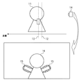
図1はデフォーカス被写体に暈け補正を適用した場合に発生するアーチファクトを説明する図である。 FIG. 1 is a diagram illustrating an artifact that occurs when blur correction is applied to a defocused subject.
撮像装置14によって人物のような被写体11を撮影した画像の暈けを補正する場合、合焦位置12の被写体像の暈けは良好に補正され、鮮明な画像が得られる。しかし、合焦位置12からずれた位置13における被写体像については、撮像光学系の暈け特性が合焦位置12とは異なり、合焦位置12と同様に暈け補正を行えば、位置13における被写体像の輪郭部には色が付く偽色が発生する。図1に示す例では、被写体像16の腕部に、被写体像16を縁取るように緑色の線(偽色15)が発生するなど、アーチファクトが発生する。
When the blur of an image obtained by photographing the subject 11 such as a person is corrected by the
本発明は、アーチファクトの発生を抑えて、撮像光学系による画像の暈けを補正することを目的とする。 An object of the present invention is to correct image blurring caused by an imaging optical system while suppressing the occurrence of artifacts.
また、目的に応じた暈け補正係数を算出し、撮像光学系による画像の暈けを補正することを他の目的とする。 Another object is to calculate a blur correction coefficient in accordance with the purpose and correct the blur of the image by the imaging optical system.
本発明は、前記の目的を達成する一手段として、以下の構成を備える。 The present invention has the following configuration as one means for achieving the above object.
本発明にかかる画像処理は、撮像デバイスから画像データを入力し、被写体からの光を前記撮像デバイスに結像する撮像光学系の状態に対応する光学伝達関数を取得し、前記撮像光学系の合焦位置からのずれに対する特性変化の評価に基づき重み係数を決定し、前記決定した重み係数に基づき、前記画像データから暈け補正の対象成分と非対象成分を生成し、前記取得した光学伝達関数暈け補正係数に基づき生成される暈け補正フィルタを使用して、前記対象成分に暈け補正を施し、前記暈け補正後の対象成分と前記非対象成分を合成した画像データを生成することを特徴とする。 In the image processing according to the present invention, image data is input from an imaging device, an optical transfer function corresponding to a state of the imaging optical system that forms an image of light from a subject on the imaging device is acquired, and a combination of the imaging optical system is obtained. A weighting factor is determined based on an evaluation of a characteristic change with respect to a deviation from a focal position, a blur correction target component and a non-target component are generated from the image data based on the determined weighting factor, and the acquired optical transfer function Using blur correction filters generated based on blur correction coefficients, blur correction is performed on the target component, and image data in which the target component after blur correction and the non-target component are combined is generated. It is characterized by.
本発明によれば、アーチファクトの発生を抑えて、撮像光学系による画像の暈けを補正することをができる。 According to the present invention, it is possible to correct blurring of an image caused by an imaging optical system while suppressing occurrence of artifacts.
また、目的に応じた暈け補正係数を算出し、撮像光学系による画像の暈けを補正することができる。 Further, it is possible to calculate a blur correction coefficient in accordance with the purpose and correct the blur of the image by the imaging optical system.
以下、本発明にかかる実施例の画像処理を図面を参照して詳細に説明する。 Hereinafter, image processing according to an embodiment of the present invention will be described in detail with reference to the drawings.
実施例1では、偽色の発生を抑えつつ、撮像光学系による画像の暈けを補正する撮像装置を説明する。 In the first embodiment, an imaging device that corrects blurring of an image by the imaging optical system while suppressing generation of false colors will be described.
[装置の構成]
図2は実施例1の撮像装置の構成例を示すブロック図である。
[Device configuration]
FIG. 2 is a block diagram illustrating a configuration example of the imaging apparatus according to the first embodiment.
図示しない被写体からの光は、撮像光学系101を介して、撮像デバイス102の受光面(撮像面)に結像する。撮像デバイス102は、結像した光を電気信号に変換する。アナログ-ディジタルコンバータ(A/D)103は、撮像デバイス102から出力される電気信号をディジタル信号(撮像データ)に変換する。なお、撮像デバイス102は、受光面に結像した光信号を受光素子ごとに電気信号に変換する光電変換デバイスである。
Light from a subject (not shown) forms an image on the light receiving surface (imaging surface) of the
画像処理部104は、A/D103から入力される撮像データを記憶部108のRAMに格納し、状態検知部107から撮像装置の撮像状態を示す状態情報(撮像光学系101の状態情報を含む)を取得する。状態検知部107は、撮像装置全体を制御するシステムコントローラ110から状態情報を得てもよいし、例えば撮像光学系101の状態情報を撮像光学系制御部106から得てもよい。
The
撮像光学系制御部106は、撮像光学系101の絞り101aの開口やレンズ101bの位置を制御して、撮像光学系101を通過する光量および撮像光学系101の合焦位置などを制御する。
The imaging optical
次に、画像処理部104は、詳細は後述するが、撮像光学系101の状態情報に応じた暈け補正係数を記憶部108のROMなどから取得し、バッファした撮像データに暈け補正を施す。画像処理部104は、暈け補正した画像データをメモリカードのような記録媒体109に格納したり、表示部105に表示する。なお、撮像光学系101を変更可能な撮像装置の場合、暈け補正係数は撮像光学系101内のメモリに格納すればよい。
Next, as will be described in detail later, the
ここで撮像光学系101の状態情報とは、撮像光学系の絞り、焦点距離(ズーム位置)、被写体までの距離、像高などの情報である。一般に暈け特性は前記のパラメータにより様々に変動するため、暈け特性に応じた補正を行うためには、前記のような暈け特性を規定するような各種情報が必要である。
Here, the state information of the imaging
[画像処理部]
図3は画像処理部104の処理を説明するフローチャートである。
[Image processing unit]
FIG. 3 is a flowchart for explaining the processing of the
画像処理部104は、バッファした撮像データをデモザイキングして画像データを生成する(S101)。なお、画像処理部104は、必要に応じて、デモザイキングに先立ち、例えば、撮像デバイス102の欠陥を補償するような前処理を撮像データに施してもよい。
The
次に、画像処理部104は、記憶部108から撮像光学系101の状態情報に応じた回復フィルタの係数(暈け補正係数)を取得し(S102)、回復フィルタを用いて、画像データの特定の画像成分に対して暈け補正を施す(S103)。
Next, the
●暈け補正の詳細
図4は暈け補正を説明するフローチャートである。
Details of blur correction FIG. 4 is a flowchart for explaining blur correction.
画像処理部104は、画像データを色成分と輝度成分に分離する(S201)。例えば画像データがRGBの3プレーンからなる場合、次式により各画素データを輝度成分Y、色成分Ca、Cbに分離する。
Y = Wr×R + Wg×G + Wb×B
Ca = R/G …(5)
Cb = B/G
ここで、Wr、Wg、Wbは重み係数。
The
Y = Wr × R + Wg × G + Wb × B
Ca = R / G (5)
Cb = B / G
Here, Wr, Wg, and Wb are weighting factors.
上式の重み係数として、Wr=Wg=Wb=1/3などが考えられる。また、上式は一例であり、輝度を表す信号と、色度を表す信号に分離すればよい。例えば、LabやYuvなどの表色系を利用して、輝度成分と色度成分を分離してもよい。 As the weighting coefficient of the above equation, Wr = Wg = Wb = 1/3 can be considered. The above equation is an example, and it may be separated into a signal representing luminance and a signal representing chromaticity. For example, the luminance component and the chromaticity component may be separated using a color system such as Lab or Yuv.
次に、画像処理部104は、暈け補正の対象成分である輝度成分画像に回復フィルタを適用し(S202)、式(5)の逆変換によって、暈け補正後の輝度成分画像と、暈け補正の非対象成分である色成分画像からRGB画像を生成する(S203)。
Next, the
[回復フィルタの構成]
レンズ設計値に基づき、RGB各色に対するPSFが計算されているとすると、輝度成分画像に対するPSFyは次式で表される。
PSFy = Wr×PSFr + Wg×PSFg + Wb×PSFb …(6)
ここで、PSFrはR成分画像に対するPSF、
PSFgはG成分画像に対するPSF、
PSFbはB成分画像に対するPSF。
[Recovery filter configuration]
If the PSF for each RGB color is calculated based on the lens design value, the PSFy for the luminance component image is expressed by the following equation.
PSFy = Wr × PSFr + Wg × PSFg + Wb × PSFb… (6)
Where PSFr is the PSF for the R component image,
PSFg is the PSF for the G component image,
PSFb is the PSF for the B component image.
式(5)に示す重み係数で各色のPSFを合成すれば、輝度成分画像に対するPSFyが得られる。このPSFyに基づき、輝度成分画像に対する回復フィルタを構成する。つまり、原色に関する撮像光学系101の暈け特性に基づき暈け補正処理の係数を決める。
If the PSFs of the respective colors are synthesized with the weighting coefficient shown in Expression (5), PSFy for the luminance component image can be obtained. Based on this PSFy, a recovery filter for the luminance component image is configured. That is, the blur correction coefficient is determined based on the blur characteristics of the imaging
このように、輝度成分に暈け補正を施して撮像光学系による暈けを補正する。一方、色成分には暈け補正を施さないので、色成分に対する暈け補正の影響を低減して、暈け補正による偽色など、アーティファクトの発生を抑制することができる。 In this way, blur correction is performed on the luminance component to correct blur due to the imaging optical system. On the other hand, since no blur correction is performed on the color components, the influence of blur correction on the color components can be reduced, and the occurrence of artifacts such as false colors due to blur correction can be suppressed.
以下、本発明にかかる実施例2の画像処理を説明する。なお、実施例2において、実施例1と略同様の構成については、同一符号を付して、その詳細説明を省略する。 The image processing according to the second embodiment of the present invention will be described below. Note that the same reference numerals in the second embodiment denote the same parts as in the first embodiment, and a detailed description thereof will be omitted.
実施例2では、アーチファクトの発生を抑えつつ、撮像光学系の暈けを低減する撮像装置を説明する。 In the second embodiment, an imaging apparatus that reduces the blur of the imaging optical system while suppressing the occurrence of artifacts will be described.
実施例1では、デフォーカス被写体の暈けを補正する際に発生する偽色を抑制するため、輝度成分の暈け特性に基づき作成した回復フィルタを使用して、輝度成分画像に暈け補正を施す方法を説明した。実施例2では、回復フィルタの基になる暈け特性を、その特性を考慮して算出し、暈け補正に適用する例を説明する。 In Example 1, in order to suppress false color generated when correcting the blur of the defocused subject, the blur correction is performed on the luminance component image using a recovery filter created based on the blur characteristic of the luminance component. The method of applying was explained. In the second embodiment, an example will be described in which blur characteristics that are the basis of a recovery filter are calculated in consideration of the characteristics and applied to blur correction.
[暈け特性の性質]
図5はデフォーカス被写体で偽色が発生する原因を説明する図で、RGBに対応する単一波長光に対するOTFをプロットした図である、
[Characteristics of profit characteristics]
FIG. 5 is a diagram for explaining the cause of false color in a defocused subject, and is a diagram plotting OTF for single wavelength light corresponding to RGB.
図5(a)は合焦位置の被写体像に対する撮像光学系のOTFを表す図である。つまり、合焦位置においては、RGBに対応するOTFのプロットは重なり、一つの曲線として描かれる。 FIG. 5 (a) is a diagram showing the OTF of the imaging optical system for the subject image at the in-focus position. That is, at the in-focus position, the OTF plots corresponding to RGB overlap and are drawn as one curve.
図5(b)は合焦位置の手前または奥にある被写体像に対する撮像光学系のOTFを表す図である。図5(b)に示す特性は、図5(a)と比較すると、RGBすべてで応答が低下し、暈けが発生していることが分かる。ただし、G成分に関しては、RおよびB成分よりも応答が強い。これは、撮像光学系の特性として、合焦位置からの変動(ずれ)に対して鈍感な(特性の変化が少ない)波長があることを意味する。 FIG. 5 (b) is a diagram showing the OTF of the imaging optical system for a subject image in front of or behind the in-focus position. The characteristics shown in FIG. 5 (b) are compared with FIG. 5 (a), and it can be seen that the response is lowered in all the RGB colors, and that the blur occurs. However, the G component has a stronger response than the R and B components. This means that as a characteristic of the imaging optical system, there is a wavelength that is insensitive to changes (shifts) from the in-focus position (small change in characteristics).
図5(c)は合焦位置の暈け特性から作成した回復フィルタの周波数特性を示す図である。この回復フィルタをデフォーカス被写体に適用すれば、暈け補正後の画像の周波数特性は、図5(b)と図5(c)の特性の掛け算になり、図5(d)に示すようになる。 FIG. 5 (c) is a diagram showing the frequency characteristics of the recovery filter created from the blur characteristics at the in-focus position. If this restoration filter is applied to a defocused subject, the frequency characteristics of the image after blur correction will be the product of the characteristics of Fig. 5 (b) and Fig. 5 (c), as shown in Fig. 5 (d). Become.
図5(d)に示すように、暈け補正後の特性はG成分が強調され、その結果、偽色が発生して画質劣化が生じる。これが、暈け補正によりデフォーカス被写体で偽色が発生するメカニズムである。 As shown in FIG. 5 (d), the G component is emphasized in the characteristic after blur correction. As a result, a false color is generated and the image quality is deteriorated. This is the mechanism by which false color occurs in a defocused subject due to blur correction.
偽色の発生を抑制する目的を考慮すると、合焦位置からの変動に対してOTFの変動が少ない波長成分だけを抽出し、当該成分だけ暈け補正を行う方法が考えられる。以下、この方法による暈け補正を説明する。 Considering the purpose of suppressing the generation of false colors, a method of extracting only a wavelength component with a small OTF variation relative to the variation from the in-focus position, and performing blur correction only for that component can be considered. Hereinafter, blur correction by this method will be described.
[暈け特性の算出]
図6は暈け特性の作成方法を示すフローチャートである。
[Calculation of profit characteristics]
FIG. 6 is a flowchart showing a method for creating a blur characteristic.
波長ごとのOTFを撮像光学系の設計値から光線追跡法などによって算出する(S301)。 The OTF for each wavelength is calculated from the design value of the imaging optical system by the ray tracing method or the like (S301).
あるいは、公差などを考慮して、より現実的な撮像光学系のOTFを計算してもよい。実際の撮像光学系には公差として、例えばレンズの取付位置のずれなど、許容できる誤差の範囲が規定されている場合がある。撮像光学系は、この公差の範囲で製造されるため、実際の撮像光学系のOTFは設計値から計算されるOTFとは若干異なることがある。そのため公差を考慮して、より現実的な撮像光学系のOTFを波長ごとに計算してもよい。 Alternatively, a more realistic imaging optical system OTF may be calculated in consideration of tolerances and the like. In an actual imaging optical system, an allowable error range such as a lens mounting position shift may be defined as a tolerance. Since the imaging optical system is manufactured within this tolerance range, the actual OTF of the imaging optical system may be slightly different from the OTF calculated from the design value. Therefore, in consideration of tolerances, a more realistic OTF of the imaging optical system may be calculated for each wavelength.
具体的には各種誤差の範囲内で複数のOTFを計算し、その平均のOTFを求めれば、現実的な撮像光学系のOTFとなる。なお公差によるOTFの変動が大きい場合には、暈け補正結果の変動も大きくなる。そこで、公差によるOTF変動が大きい空間周波数で回復の度合いを抑えるように回復フィルタを構成して、暈け補正後の品質を揃えるなどの工夫も考えられる。 Specifically, if a plurality of OTFs are calculated within a range of various errors and an average OTF is obtained, an actual OTF of the imaging optical system is obtained. In addition, when the fluctuation of the OTF due to tolerance is large, the fluctuation of the blur correction result also becomes large. In view of this, it is conceivable to construct a recovery filter so as to suppress the degree of recovery at a spatial frequency where OTF fluctuation due to tolerance is large, and to make the quality after blur correction uniform.
波長の刻みは、可視光の波長範囲を例えば10nmおきに刻めばよい。刻みは、細かいほど精度が上がるが、反面、処理負荷が大きくなる。この点を考慮して、刻みを適宜定める。 For the wavelength step, the visible light wavelength range may be cut, for example, every 10 nm. The finer the step, the higher the accuracy, but on the other hand, the processing load increases. In consideration of this point, the step is appropriately determined.
次に、ある重み係数を与えて波長ごとのOTFを合成する(S302)。図7は波長ごとのOTFを合成する概念図である。合成は、各波長のOTFを加重平均すればよい。合成に使用する重み係数は、繰り返し処理によって最適化される係数である。重み係数の初期値は、例えば全波長で一律に設定すればよい。また、上記の目的(偽色の発生の抑制)を達成するには、合焦位置からの変動に対するOTFに注目する必要がある。従って、合焦位置のOTFに加え、同様に、合焦位置からずれた複数の位置の波長ごとのOTFを計算し、同じ重み係数を使用して波長ごとのOTFを合成する。 Next, an OTF for each wavelength is synthesized by giving a certain weighting coefficient (S302). FIG. 7 is a conceptual diagram for synthesizing the OTF for each wavelength. For the synthesis, the OTF of each wavelength may be weighted average. The weighting coefficient used for synthesis is a coefficient that is optimized by iterative processing. The initial value of the weighting factor may be set uniformly for all wavelengths, for example. Further, in order to achieve the above-mentioned purpose (suppression of generation of false color), it is necessary to pay attention to OTF with respect to variation from the in-focus position. Therefore, in addition to the OTF at the focus position, similarly, the OTF for each wavelength at a plurality of positions shifted from the focus position is calculated, and the OTF for each wavelength is synthesized using the same weighting factor.
次に、評価式に基づき、合焦位置の合成後のOTF(以下、合焦位置OTF)と、合焦位置からずれた複数の位置の合成後のOTF(以下、非合焦位置OTF)を比較して、それらの変動を評価する。例えば、合焦位置OTFおよび複数の非合焦位置OTFからなるOTFの集合の標準偏差を評価値として計算し(S303)、評価値が所定の閾値未満(評価値<閾値)になれば重み係数を適切と判断する(S304)。その場合、ステップS302で合成に使用した重み係数、および、ステップS302で計算した合焦位置OTFを暈け補正に使用する。 Next, based on the evaluation formula, the OTF after combining the focus position (hereinafter referred to as the focus position OTF) and the OTF after combining the multiple positions shifted from the focus position (hereinafter referred to as the non-focus position OTF) Compare and evaluate those variations. For example, the standard deviation of a set of OTFs consisting of a focus position OTF and a plurality of non-focus positions OTF is calculated as an evaluation value (S303), and if the evaluation value is less than a predetermined threshold (evaluation value <threshold), a weight coefficient Is determined to be appropriate (S304). In that case, the weighting factor used for the synthesis in step S302 and the in-focus position OTF calculated in step S302 are used for blur correction.
また、評価値≧閾値の場合は、重み係数を変更して(S305)、処理をステップS302に戻し、評価値<閾値を満足するまで重み係数を変更する。 If evaluation value ≧ threshold, the weighting coefficient is changed (S305), the process returns to step S302, and the weighting coefficient is changed until evaluation value <threshold is satisfied.
以上の処理により、合焦位置からのずれに対して特性の変化が少ない波長に対する重み係数を大きくした合焦位置OTFを得ることができる。なお、合焦位置からのずれに対する特性の変化が少ない波長は、必ずしも一つとは限らない。従って、上記の処理によって二組の重み係数、つまり、合焦位置からのずれに対する特性の変化が少ない二つの波長の重みを大きくする二組の重み係数を得て、それら重み係数の平均値、および、それら合焦位置OTFの合成を暈け補正に使用してもよい。 With the above processing, it is possible to obtain an in-focus position OTF in which a weighting coefficient for a wavelength with a small change in characteristics with respect to a deviation from the in-focus position is increased. Note that the wavelength having a small change in characteristics with respect to deviation from the in-focus position is not necessarily one. Therefore, two sets of weighting factors are obtained by the above processing, that is, two sets of weighting factors that increase the weights of two wavelengths with little change in characteristics with respect to deviation from the in-focus position, and the average value of the weighting factors, Further, the synthesis of these in-focus positions OTF may be used for blur correction.
[画像処理部]
図8は実施例2の画像処理部104の処理を説明するフローチャートである。
[Image processing unit]
FIG. 8 is a flowchart illustrating the processing of the
画像処理部104は、バッファした撮像データをデモザイキングして画像データを生成する(S401)。なお、画像処理部104は、必要に応じて、デモザイキングに先立ち、例えば、撮像デバイス102の欠陥を補償するような前処理を撮像データに施してもよい。
The
次に、画像処理部104は、記憶部108から撮像光学系101の状態情報に応じた合焦位置およびその前後の、波長ごとのOTFを取得し(S402)、上記の処理によって重み係数を決定する。そして、合焦位置OTFを算出して、回復フィルタを作成(暈け補正係数を算出)する(S403)。なお、撮像光学系101の状態情報に対応した暈け補正係数と重み係数を予め算出して記憶部108のテーブルに記録しておいてもよい。そうすれば、テーブルを参照して撮像光学系101の状態情報から暈け補正係数と重み係数を取得することができる。なお、撮像光学系101を変更可能な撮像装置の場合、当該テーブルは撮像光学系101内のメモリに格納すればよい。
Next, the
次に、画像処理部104は、暈け補正対象の画像データを補正対象成分と、非補正対象成分に分離する(S404)。画像データを補正対象成分と非補正対象成分に分離する意味は次のとおりである。
Next, the
合焦位置からのずれに対して特性の変化が少ない波長を考慮して算出した重み係数w(λ)と同様の分光分布の光に対して、撮像光学系の合焦位置からのずれに対する特性変化は少ないと言える。このような分光分布の光を撮影すると、そのRGB値は(Wr', Wg', Wb')に比例する。従って、RGB値を三次元ベクトルとして考えた場合、ベクトル(Wr', Wg', Wb')への射影が合焦位置からのずれに対して特性の変化が少ない成分になる。また逆に、ベクトル(Wr', Wg', Wb')に直交する成分が合焦位置からのずれに対して特性変化が大きい成分である。補正対象成分Jは、RGB値のベクトル(Wr', Wg', Wb')への射影成分であるため、補正対象成分Jは合焦位置からのずれに対して暈け特性の変化が少ない。 Characteristics with respect to deviation from the in-focus position of the imaging optical system for light with a spectral distribution similar to the weighting coefficient w (λ) calculated considering the wavelength with little change in characteristics with respect to deviation from the in-focus position There can be little change. When light having such a spectral distribution is photographed, the RGB value is proportional to (Wr ′, Wg ′, Wb ′). Therefore, when the RGB value is considered as a three-dimensional vector, the projection onto the vector (Wr ′, Wg ′, Wb ′) becomes a component with little change in characteristics with respect to the deviation from the in-focus position. Conversely, the component orthogonal to the vector (Wr ′, Wg ′, Wb ′) is a component whose characteristic change is large with respect to the deviation from the in-focus position. Since the correction target component J is a projection component onto a vector of RGB values (Wr ′, Wg ′, Wb ′), the correction target component J has little change in blur characteristics with respect to deviation from the in-focus position.
画像処理部104は、ステップS403で決定した重み係数をw(λ)とし、RGBチャネルそれぞれの分光感度をRr(λ)、Rg(λ)、Rb(λ)として、分離係数Wr'、Wg'、Wb'を次式によって計算する。
Wr' = ∫Rr(λ)w(λ)dλ
Wg' = ∫Rg(λ)w(λ)dλ …(7)
Wb' = ∫Rb(λ)w(λ)dλ
The
Wr '= ∫Rr (λ) w (λ) dλ
Wg '= ∫Rg (λ) w (λ) dλ (7)
Wb '= ∫Rb (λ) w (λ) dλ
続いて、画像処理部104は、分離係数を用いてRGBプレーンから次式によって補正対象成分Jを計算する。
J = Wr'×R + Wg'×G + Wb'×B …(8)
Subsequently, the
J = Wr '× R + Wg' × G + Wb '× B (8)
式(8)は実施例1の輝度成分画像の式(5)に類似する。しかし、係数Wr'、Wg'、Wb'は特定の目的に適うよう選定した重み係数w(λ)を用いて算出されている。この点で、実施例1の係数Wr、Wg、Wbとは異なる。 Expression (8) is similar to Expression (5) of the luminance component image of the first embodiment. However, the coefficients Wr ′, Wg ′, and Wb ′ are calculated using the weighting coefficient w (λ) selected to suit a specific purpose. This is different from the coefficients Wr, Wg, and Wb of the first embodiment.
続いて、画像処理部104は、非補正対象成分Ca'、Cb'を次式によって計算する。
Ca' = Ca'r×R + Ca'g×G + Ca'b×B
Cb' = Cb'r×R + Cb'g×G + Cb'b×B …(9)
Subsequently, the
Ca '= Ca'r x R + Ca'g x G + Ca'b x B
Cb '= Cb'r x R + Cb'g x G + Cb'b x B (9)
なお、式(9)の係数Ca'r、Ca'g、Ca'b、Cb'r、Cb'g、Cb'bは次式を満たすように作成する。
Wr'×Ca'r + Wg'×Ca'g + Wb'×Ca'b = 0
Wr'×Cb'r + Wg'×Cb'g + Wb'×Cb'b = 0 …(10)
The coefficients Ca′r, Ca′g, Ca′b, Cb′r, Cb′g, and Cb′b in Expression (9) are created so as to satisfy the following expression.
Wr '× Ca'r + Wg' × Ca'g + Wb '× Ca'b = 0
Wr '× Cb'r + Wg' × Cb'g + Wb '× Cb'b = 0 (10)
次に、画像処理部104は、ステップS403で作成した回復フィルタを用いて、補正対象成分Jに暈け補正を施す(S405)。そして、式(8)(9)の逆変換によって、暈け補正後の補正対象成分Jと、非補正対象成分Ca'、Cb'からRGB画像を生成する(S406)。
Next, the
このように、目的(偽色の発生の抑制)に応じて、合焦位置からのずれに対する特性の変化が少ない波長の重み係数を大きくして、波長ごとのOTFを合成する。そして、合焦位置からのずれに対する特性の変化が少ない波長成分に対応する画像成分を抽出して、当該画像成分に合成したOTFに基づく暈け補正を施す。その結果、偽色の発生を抑制した暈け補正が可能になる。 In this way, the OTF for each wavelength is synthesized by increasing the weighting coefficient of the wavelength with little change in characteristics with respect to the deviation from the in-focus position in accordance with the purpose (suppression of generation of false color). Then, an image component corresponding to a wavelength component with little change in characteristics with respect to the deviation from the in-focus position is extracted, and blur correction based on the OTF synthesized with the image component is performed. As a result, it is possible to perform blur correction that suppresses the occurrence of false colors.
なお、上記では目的として偽色の発生の抑制を例に挙げたが、例えば、特定の波長成分を有する被写体画像のみ暈け補正を施すなどが挙げられる。例えば、人間の肌の分光反射率に基づき波長ごとに合成したOTFを使用して、人間の肌に対応する画像成分に暈け補正を施せば、人物像の暈けを低減した画像を得ることができる。また、このような暈け補正は、通常、RGB3プレーンについて必要な暈け補正を、人物像に相関が高い1プレーンに絞って行うことができるため、高速な処理を実現することができる。 In the above description, the purpose is to suppress the generation of false colors as an example. However, for example, blur correction is performed only on a subject image having a specific wavelength component. For example, using an OTF synthesized for each wavelength based on the spectral reflectance of human skin, and applying blur correction to the image components corresponding to human skin, an image with reduced human image blur can be obtained. Can do. In addition, such blur correction can usually be performed for the RGB3 plane by focusing on one plane having a high correlation with a human image, and thus high-speed processing can be realized.
また、撮像光学系の製造ばらつきが特定の波長について大きい場合、製造ばらつきの少ない波長に基づき波長ごとに合成したOTFを使用して、製造ばらつきの少ない波長に対応する画像成分に暈け補正を施すことができる。こうすれば、製造ばらつきの影響によるアーチファクトの発生を抑制した暈け補正を実現することができる。 In addition, when the manufacturing variation of the imaging optical system is large for a specific wavelength, blur correction is applied to the image component corresponding to the wavelength with a small manufacturing variation using an OTF synthesized for each wavelength based on the wavelength with a small manufacturing variation. be able to. By doing so, it is possible to realize blur correction that suppresses the occurrence of artifacts due to the influence of manufacturing variations.
このように、目的に応じて暈け特性を算出し、算出した暈け特性に基づき撮像光学系の暈けを補正して、暈け補正による偽色など、アーチファクトの発生を抑制することができる。 In this way, the blur characteristics are calculated according to the purpose, and the blur of the imaging optical system is corrected based on the calculated blur characteristics, thereby suppressing the occurrence of artifacts such as false colors due to blur correction. .
[他の実施例]
なお、本発明は、複数の機器(例えばコンピュータ、インタフェイス機器、リーダ、プリンタなど)から構成されるシステムに適用しても、一つの機器からなる装置(例えば、複写機、ファクシミリ装置、制御装置など)に適用してもよい。
[Other embodiments]
Note that the present invention can be applied to a system composed of a plurality of devices (for example, a computer, an interface device, a reader, a printer, etc.), or a device (for example, a copier, a facsimile machine, a control device) composed of a single device. Etc.).
また、本発明の目的は、上記実施例の機能を実現するコンピュータプログラムを記録した記録媒体または記憶媒体をシステムまたは装置に供給する。そして、そのシステムまたは装置のコンピュータ(CPUやMPU)が前記コンピュータプログラムを実行することでも達成される。この場合、記録媒体から読み出されたソフトウェア自体が上記実施例の機能を実現することになり、そのコンピュータプログラムと、そのコンピュータプログラムを記憶する、コンピュータが読み取り可能な記録媒体は本発明を構成する。 Another object of the present invention is to supply a recording medium or a recording medium recording a computer program for realizing the functions of the above embodiments to a system or apparatus. This can also be achieved by the computer (CPU or MPU) of the system or apparatus executing the computer program. In this case, the software read from the recording medium itself realizes the functions of the above embodiments, and the computer program and the computer-readable recording medium storing the computer program constitute the present invention. .
また、前記コンピュータプログラムの実行により上記機能が実現されるだけではない。つまり、そのコンピュータプログラムの指示により、コンピュータ上で稼働するオペレーティングシステム(OS)および/または第一の、第二の、第三の、…プログラムなどが実際の処理の一部または全部を行い、それによって上記機能が実現される場合も含む。 Further, the above functions are not only realized by the execution of the computer program. That is, according to the instruction of the computer program, the operating system (OS) and / or the first, second, third,... This includes the case where the above function is realized.
また、前記コンピュータプログラムがコンピュータに接続された機能拡張カードやユニットなどのデバイスのメモリに書き込まれていてもよい。つまり、そのコンピュータプログラムの指示により、第一の、第二の、第三の、…デバイスのCPUなどが実際の処理の一部または全部を行い、それによって上記機能が実現される場合も含む。 The computer program may be written in a memory of a device such as a function expansion card or unit connected to the computer. That is, it includes the case where the CPU of the first, second, third,... Device performs part or all of the actual processing according to the instructions of the computer program, thereby realizing the above functions.
本発明を前記記録媒体に適用する場合、その記録媒体には、先に説明したフローチャートに対応または関連するコンピュータプログラムが格納される。 When the present invention is applied to the recording medium, the recording medium stores a computer program corresponding to or related to the flowchart described above.
Claims (10)
被写体からの光を前記撮像デバイスに結像する撮像光学系の状態に対応する光学伝達関数を取得する取得手段と、
前記撮像光学系の合焦位置からのずれに対する特性変化の評価に基づき重み係数を決定する決定手段と、
前記決定した重み係数に基づき、前記画像データから暈け補正の対象成分と非対象成分を生成する生成手段と、
前記取得した光学伝達関数に基づき生成される暈け補正フィルタを使用して、前記対象成分に暈け補正を施す補正手段と、
前記暈け補正後の対象成分と前記非対象成分を合成した画像データを生成する合成手段とを有することを特徴とする画像処理装置。 Input means for inputting image data from the imaging device;
Obtaining means for obtaining an optical transfer function corresponding to a state of an imaging optical system that forms an image of light from a subject on the imaging device;
Determining means for determining a weighting factor based on an evaluation of a characteristic change with respect to a deviation from the in-focus position of the imaging optical system;
Generating means for generating a target component and a non-target component for blur correction from the image data based on the determined weight coefficient ;
Correction means for performing blur correction on the target component using a blur correction filter generated based on the acquired optical transfer function ;
An image processing apparatus comprising: a combining unit that generates image data obtained by combining the target component after blur correction and the non-target component.
さらに、前記重み係数を使用して、前記合焦位置と前記合焦位置の前後における、前記波長ごとの光学伝達関数それぞれを加重平均し、それら加重平均の標準偏差が所定の閾値未満を示す重み係数における前記合焦位置に対応する加重平均から前記暈け補正フィルタとして暈け補正係数を算出する算出手段を有することを特徴とする請求項1から請求項3の何れか一項に記載された画像処理装置。 The acquisition means acquires the optical transfer function for each wavelength before and after the in-focus position and the in-focus position of the imaging optical system,
Furthermore , using the weighting factor, the weighted average of the optical transfer function for each wavelength before and after the in-focus position and the in-focus position, and the standard deviation of the weighted average is less than a predetermined threshold according to any one of claims 1 to 3, characterized in that it comprises a calculating means for calculating a blur correction coefficient as the blur correction filter from the weighted average corresponding to the focus position in the coefficient Image processing device.
被写体からの光を前記撮像デバイスに結像する撮像光学系の状態に対応する光学伝達関数を取得し、
前記撮像光学系の合焦位置からのずれに対する特性変化の評価に基づき重み係数を決定し、
前記決定した重み係数に基づき、前記画像データから暈け補正の対象成分と非対象成分を生成し、
前記取得した光学伝達関数暈け補正係数に基づき生成される暈け補正フィルタを使用して、前記対象成分に暈け補正を施し、
前記暈け補正後の対象成分と前記非対象成分を合成した画像データを生成することを特徴とする画像処理方法。 Input image data from the imaging device,
Obtaining an optical transfer function corresponding to a state of an imaging optical system that forms an image of light from a subject on the imaging device;
Determining a weighting factor based on an evaluation of a characteristic change with respect to a deviation from the in-focus position of the imaging optical system;
Based on the determined weighting factor, a blur correction target component and a non-target component are generated from the image data,
Apply blur correction to the target component using a blur correction filter generated based on the acquired optical transfer function blur correction coefficient,
An image processing method, comprising: generating image data obtained by combining the target component after blur correction and the non-target component.
Priority Applications (3)
| Application Number | Priority Date | Filing Date | Title |
|---|---|---|---|
| JP2008318937A JP5235642B2 (en) | 2008-12-15 | 2008-12-15 | Image processing apparatus and method |
| US13/124,419 US8482659B2 (en) | 2008-12-15 | 2009-11-11 | Image processing apparatus and image processing method |
| PCT/JP2009/069518 WO2010071001A1 (en) | 2008-12-15 | 2009-11-11 | Image processing apparatus and image processing method |
Applications Claiming Priority (1)
| Application Number | Priority Date | Filing Date | Title |
|---|---|---|---|
| JP2008318937A JP5235642B2 (en) | 2008-12-15 | 2008-12-15 | Image processing apparatus and method |
Publications (3)
| Publication Number | Publication Date |
|---|---|
| JP2010140442A JP2010140442A (en) | 2010-06-24 |
| JP2010140442A5 JP2010140442A5 (en) | 2011-10-06 |
| JP5235642B2 true JP5235642B2 (en) | 2013-07-10 |
Family
ID=42268676
Family Applications (1)
| Application Number | Title | Priority Date | Filing Date |
|---|---|---|---|
| JP2008318937A Active JP5235642B2 (en) | 2008-12-15 | 2008-12-15 | Image processing apparatus and method |
Country Status (3)
| Country | Link |
|---|---|
| US (1) | US8482659B2 (en) |
| JP (1) | JP5235642B2 (en) |
| WO (1) | WO2010071001A1 (en) |
Families Citing this family (18)
| Publication number | Priority date | Publication date | Assignee | Title |
|---|---|---|---|---|
| JP5454348B2 (en) * | 2010-05-12 | 2014-03-26 | ソニー株式会社 | Imaging apparatus and image processing apparatus |
| JP2012256118A (en) * | 2011-06-07 | 2012-12-27 | Canon Inc | Image restoration device and method thereof |
| JP5361976B2 (en) * | 2011-08-25 | 2013-12-04 | キヤノン株式会社 | Image processing program, image processing method, image processing apparatus, and imaging apparatus |
| AU2011224051B2 (en) * | 2011-09-14 | 2014-05-01 | Canon Kabushiki Kaisha | Determining a depth map from images of a scene |
| TWI551113B (en) * | 2011-12-27 | 2016-09-21 | 鴻海精密工業股份有限公司 | 3d imaging module and 3d imaging method |
| CN103188424B (en) * | 2011-12-27 | 2018-10-09 | 财富文化产业集团(深圳)有限公司 | 3D imaging modules and 3D imaging methods |
| CN103188499B (en) * | 2011-12-27 | 2016-05-04 | 鸿富锦精密工业(深圳)有限公司 | 3D imaging modules and 3D formation method |
| TWI510056B (en) * | 2011-12-27 | 2015-11-21 | Hon Hai Prec Ind Co Ltd | 3d imaging module and 3d imaging method |
| CN105009579B (en) | 2013-03-04 | 2017-01-25 | 富士胶片株式会社 | Restoration filter generation device and method, image processing device and method, and imaging device |
| JP5851650B2 (en) | 2013-03-04 | 2016-02-03 | 富士フイルム株式会社 | Restoration filter generation apparatus and method, image processing apparatus, imaging apparatus, restoration filter generation program, and recording medium |
| WO2014136322A1 (en) | 2013-03-04 | 2014-09-12 | 富士フイルム株式会社 | Restoration filter generation device and method, image processing device and method, imaging device, program, and recording medium |
| WO2014148074A1 (en) | 2013-03-18 | 2014-09-25 | 富士フイルム株式会社 | Restoration filter generation device and method, image processing device and method, image capturing apparatus, program, and recording medium |
| JP6627207B2 (en) * | 2014-08-01 | 2020-01-08 | 株式会社ニコン | Lens barrel and camera body |
| US9894298B1 (en) * | 2014-09-26 | 2018-02-13 | Amazon Technologies, Inc. | Low light image processing |
| CN107534727B (en) | 2015-04-23 | 2020-06-26 | 富士胶片株式会社 | Image processing device, imaging device, image processing method, and computer-readable non-transitory tangible recording medium having image processing program recorded thereon |
| JP6240813B2 (en) | 2015-04-23 | 2017-11-29 | 富士フイルム株式会社 | Image processing apparatus, imaging apparatus, image processing method, and image processing program |
| KR101862490B1 (en) * | 2016-12-13 | 2018-05-29 | 삼성전기주식회사 | image correct processor and computer readable recording medium |
| KR20210088960A (en) * | 2020-01-07 | 2021-07-15 | 삼성전자주식회사 | Image artifacts processing method and apparatus |
Family Cites Families (8)
| Publication number | Priority date | Publication date | Assignee | Title |
|---|---|---|---|---|
| JP2003275171A (en) * | 2002-01-18 | 2003-09-30 | Olympus Optical Co Ltd | Capsule endoscope |
| US20030158503A1 (en) * | 2002-01-18 | 2003-08-21 | Shinya Matsumoto | Capsule endoscope and observation system that uses it |
| JP4385890B2 (en) * | 2003-10-07 | 2009-12-16 | セイコーエプソン株式会社 | Image processing method, frequency component compensation unit, image processing apparatus including the frequency component compensation unit, and image processing program |
| JP2007156749A (en) * | 2005-12-02 | 2007-06-21 | Ricoh Co Ltd | Image input device |
| EP1926047A1 (en) * | 2006-11-21 | 2008-05-28 | STMicroelectronics (Research & Development) Limited | Artefact Removal from Phase Encoded Images |
| JP4818957B2 (en) * | 2007-02-27 | 2011-11-16 | 京セラ株式会社 | Imaging apparatus and method thereof |
| JP5159361B2 (en) * | 2007-03-30 | 2013-03-06 | キヤノン株式会社 | interchangeable lens |
| JP4984140B2 (en) * | 2007-05-30 | 2012-07-25 | 富士フイルム株式会社 | Image processing apparatus, image processing method, imaging apparatus, imaging method, and program |
-
2008
- 2008-12-15 JP JP2008318937A patent/JP5235642B2/en active Active
-
2009
- 2009-11-11 US US13/124,419 patent/US8482659B2/en active Active
- 2009-11-11 WO PCT/JP2009/069518 patent/WO2010071001A1/en active Application Filing
Also Published As
| Publication number | Publication date |
|---|---|
| JP2010140442A (en) | 2010-06-24 |
| WO2010071001A1 (en) | 2010-06-24 |
| US20110199514A1 (en) | 2011-08-18 |
| US8482659B2 (en) | 2013-07-09 |
Similar Documents
| Publication | Publication Date | Title |
|---|---|---|
| JP5235642B2 (en) | Image processing apparatus and method | |
| US8754957B2 (en) | Image processing apparatus and method | |
| JP5188651B2 (en) | Image processing apparatus and imaging apparatus using the same | |
| JP5284537B2 (en) | Image processing apparatus, image processing method, image processing program, and imaging apparatus using the same | |
| JP6525718B2 (en) | Image processing apparatus, control method therefor, and control program | |
| JP5546229B2 (en) | Image processing method, image processing apparatus, imaging apparatus, and image processing program | |
| JP5132401B2 (en) | Image processing apparatus and image processing method | |
| KR101536162B1 (en) | Image processing apparatus and method | |
| US8482627B2 (en) | Information processing apparatus and method | |
| US8988546B2 (en) | Image processing device, image processing method, image capturing device, and program | |
| JP2011123589A5 (en) | ||
| JP5917048B2 (en) | Image processing apparatus, image processing method, and program | |
| JP5479187B2 (en) | Image processing apparatus and imaging apparatus using the same | |
| JP2013055623A (en) | Image processing apparatus, image processing method, information recording medium, and program | |
| JP2009284009A (en) | Image processor, imaging device, and image processing method | |
| CN112073603B (en) | Image processing apparatus, image capturing apparatus, image processing method, and storage medium | |
| JP5284183B2 (en) | Image processing apparatus and method | |
| JP7183015B2 (en) | Image processing device, image processing method, and program | |
| JP6238673B2 (en) | Image processing apparatus, imaging apparatus, imaging system, image processing method, image processing program, and storage medium | |
| JP2013055622A (en) | Image processing apparatus, image processing method, information recording medium, and program | |
| JP6604737B2 (en) | Image processing apparatus, imaging apparatus, image processing method, image processing program, and storage medium | |
| JP2017224906A (en) | Image processing method, imaging apparatus using the same, image processing system, and image processing program | |
| JP2019186905A (en) | Image processing apparatus, image processing method and program | |
| JP2017118293A (en) | Image processing apparatus, imaging apparatus, image processing method, image processing program, and storage medium |
Legal Events
| Date | Code | Title | Description |
|---|---|---|---|
| A521 | Request for written amendment filed |
Free format text: JAPANESE INTERMEDIATE CODE: A523 Effective date: 20110823 |
|
| A621 | Written request for application examination |
Free format text: JAPANESE INTERMEDIATE CODE: A621 Effective date: 20110823 |
|
| TRDD | Decision of grant or rejection written | ||
| A01 | Written decision to grant a patent or to grant a registration (utility model) |
Free format text: JAPANESE INTERMEDIATE CODE: A01 Effective date: 20130225 |
|
| A61 | First payment of annual fees (during grant procedure) |
Free format text: JAPANESE INTERMEDIATE CODE: A61 Effective date: 20130326 |
|
| R151 | Written notification of patent or utility model registration |
Ref document number: 5235642 Country of ref document: JP Free format text: JAPANESE INTERMEDIATE CODE: R151 |
|
| FPAY | Renewal fee payment (event date is renewal date of database) |
Free format text: PAYMENT UNTIL: 20160405 Year of fee payment: 3 |