WO2014002777A1 - Process for producing porous metal body and porous metal body - Google Patents
Process for producing porous metal body and porous metal body Download PDFInfo
- Publication number
- WO2014002777A1 WO2014002777A1 PCT/JP2013/066293 JP2013066293W WO2014002777A1 WO 2014002777 A1 WO2014002777 A1 WO 2014002777A1 JP 2013066293 W JP2013066293 W JP 2013066293W WO 2014002777 A1 WO2014002777 A1 WO 2014002777A1
- Authority
- WO
- WIPO (PCT)
- Prior art keywords
- resin
- porous
- metal
- thickness
- film
- Prior art date
Links
Images


Classifications
-
- B—PERFORMING OPERATIONS; TRANSPORTING
- B22—CASTING; POWDER METALLURGY
- B22F—WORKING METALLIC POWDER; MANUFACTURE OF ARTICLES FROM METALLIC POWDER; MAKING METALLIC POWDER; APPARATUS OR DEVICES SPECIALLY ADAPTED FOR METALLIC POWDER
- B22F3/00—Manufacture of workpieces or articles from metallic powder characterised by the manner of compacting or sintering; Apparatus specially adapted therefor ; Presses and furnaces
- B22F3/10—Sintering only
- B22F3/11—Making porous workpieces or articles
- B22F3/1121—Making porous workpieces or articles by using decomposable, meltable or sublimatable fillers
- B22F3/1137—Making porous workpieces or articles by using decomposable, meltable or sublimatable fillers by coating porous removable preforms
-
- C—CHEMISTRY; METALLURGY
- C22—METALLURGY; FERROUS OR NON-FERROUS ALLOYS; TREATMENT OF ALLOYS OR NON-FERROUS METALS
- C22C—ALLOYS
- C22C1/00—Making non-ferrous alloys
- C22C1/08—Alloys with open or closed pores
- C22C1/081—Casting porous metals into porous preform skeleton without foaming
- C22C1/082—Casting porous metals into porous preform skeleton without foaming with removal of the preform
-
- C—CHEMISTRY; METALLURGY
- C23—COATING METALLIC MATERIAL; COATING MATERIAL WITH METALLIC MATERIAL; CHEMICAL SURFACE TREATMENT; DIFFUSION TREATMENT OF METALLIC MATERIAL; COATING BY VACUUM EVAPORATION, BY SPUTTERING, BY ION IMPLANTATION OR BY CHEMICAL VAPOUR DEPOSITION, IN GENERAL; INHIBITING CORROSION OF METALLIC MATERIAL OR INCRUSTATION IN GENERAL
- C23C—COATING METALLIC MATERIAL; COATING MATERIAL WITH METALLIC MATERIAL; SURFACE TREATMENT OF METALLIC MATERIAL BY DIFFUSION INTO THE SURFACE, BY CHEMICAL CONVERSION OR SUBSTITUTION; COATING BY VACUUM EVAPORATION, BY SPUTTERING, BY ION IMPLANTATION OR BY CHEMICAL VAPOUR DEPOSITION, IN GENERAL
- C23C14/00—Coating by vacuum evaporation, by sputtering or by ion implantation of the coating forming material
- C23C14/06—Coating by vacuum evaporation, by sputtering or by ion implantation of the coating forming material characterised by the coating material
- C23C14/14—Metallic material, boron or silicon
- C23C14/20—Metallic material, boron or silicon on organic substrates
- C23C14/205—Metallic material, boron or silicon on organic substrates by cathodic sputtering
-
- H—ELECTRICITY
- H01—ELECTRIC ELEMENTS
- H01M—PROCESSES OR MEANS, e.g. BATTERIES, FOR THE DIRECT CONVERSION OF CHEMICAL ENERGY INTO ELECTRICAL ENERGY
- H01M4/00—Electrodes
- H01M4/02—Electrodes composed of, or comprising, active material
- H01M4/64—Carriers or collectors
- H01M4/66—Selection of materials
- H01M4/661—Metal or alloys, e.g. alloy coatings
-
- H—ELECTRICITY
- H01—ELECTRIC ELEMENTS
- H01M—PROCESSES OR MEANS, e.g. BATTERIES, FOR THE DIRECT CONVERSION OF CHEMICAL ENERGY INTO ELECTRICAL ENERGY
- H01M4/00—Electrodes
- H01M4/02—Electrodes composed of, or comprising, active material
- H01M4/64—Carriers or collectors
- H01M4/70—Carriers or collectors characterised by shape or form
- H01M4/76—Containers for holding the active material, e.g. tubes, capsules
- H01M4/762—Porous or perforated metallic containers
-
- H—ELECTRICITY
- H01—ELECTRIC ELEMENTS
- H01M—PROCESSES OR MEANS, e.g. BATTERIES, FOR THE DIRECT CONVERSION OF CHEMICAL ENERGY INTO ELECTRICAL ENERGY
- H01M4/00—Electrodes
- H01M4/02—Electrodes composed of, or comprising, active material
- H01M4/64—Carriers or collectors
- H01M4/70—Carriers or collectors characterised by shape or form
- H01M4/80—Porous plates, e.g. sintered carriers
-
- H—ELECTRICITY
- H01—ELECTRIC ELEMENTS
- H01M—PROCESSES OR MEANS, e.g. BATTERIES, FOR THE DIRECT CONVERSION OF CHEMICAL ENERGY INTO ELECTRICAL ENERGY
- H01M4/00—Electrodes
- H01M4/86—Inert electrodes with catalytic activity, e.g. for fuel cells
-
- H—ELECTRICITY
- H01—ELECTRIC ELEMENTS
- H01M—PROCESSES OR MEANS, e.g. BATTERIES, FOR THE DIRECT CONVERSION OF CHEMICAL ENERGY INTO ELECTRICAL ENERGY
- H01M4/00—Electrodes
- H01M4/86—Inert electrodes with catalytic activity, e.g. for fuel cells
- H01M4/88—Processes of manufacture
- H01M4/8803—Supports for the deposition of the catalytic active composition
- H01M4/8814—Temporary supports, e.g. decal
-
- Y—GENERAL TAGGING OF NEW TECHNOLOGICAL DEVELOPMENTS; GENERAL TAGGING OF CROSS-SECTIONAL TECHNOLOGIES SPANNING OVER SEVERAL SECTIONS OF THE IPC; TECHNICAL SUBJECTS COVERED BY FORMER USPC CROSS-REFERENCE ART COLLECTIONS [XRACs] AND DIGESTS
- Y02—TECHNOLOGIES OR APPLICATIONS FOR MITIGATION OR ADAPTATION AGAINST CLIMATE CHANGE
- Y02E—REDUCTION OF GREENHOUSE GAS [GHG] EMISSIONS, RELATED TO ENERGY GENERATION, TRANSMISSION OR DISTRIBUTION
- Y02E60/00—Enabling technologies; Technologies with a potential or indirect contribution to GHG emissions mitigation
- Y02E60/10—Energy storage using batteries
-
- Y—GENERAL TAGGING OF NEW TECHNOLOGICAL DEVELOPMENTS; GENERAL TAGGING OF CROSS-SECTIONAL TECHNOLOGIES SPANNING OVER SEVERAL SECTIONS OF THE IPC; TECHNICAL SUBJECTS COVERED BY FORMER USPC CROSS-REFERENCE ART COLLECTIONS [XRACs] AND DIGESTS
- Y02—TECHNOLOGIES OR APPLICATIONS FOR MITIGATION OR ADAPTATION AGAINST CLIMATE CHANGE
- Y02E—REDUCTION OF GREENHOUSE GAS [GHG] EMISSIONS, RELATED TO ENERGY GENERATION, TRANSMISSION OR DISTRIBUTION
- Y02E60/00—Enabling technologies; Technologies with a potential or indirect contribution to GHG emissions mitigation
- Y02E60/30—Hydrogen technology
- Y02E60/50—Fuel cells
Definitions
- the present invention relates to a method for producing a metal porous body by forming a metal film on a resin surface by a metal sputtering method, and in particular, a metal porous body that can be suitably used for applications such as various filters and battery electrodes, and the production thereof. Regarding the method.
- Metal porous bodies having a three-dimensional network structure are used in various fields such as various filters, catalyst carriers, and battery electrodes.
- cermet made of nickel (manufactured by Sumitomo Electric Industries, Ltd .: registered trademark) is used as an electrode material for batteries such as nickel metal hydride batteries and nickel cadmium batteries.
- Celmet is a metal porous body having continuous air holes, and has a feature of high porosity (90% or more) compared to other porous bodies such as a metal nonwoven fabric. This can be obtained by forming a nickel layer on the surface of the porous resin skeleton having continuous air holes such as urethane foam, then heat-treating it to decompose the foamed resin molding, and further reducing the nickel.
- the formation of the nickel layer is performed by depositing nickel by electroplating after applying carbon powder or the like to the surface of the skeleton of the foamed resin molded body and conducting a conductive treatment.
- Aluminum also has excellent features such as conductivity, corrosion resistance, and light weight.
- a positive electrode of a lithium ion battery in which an active material such as lithium cobaltate is applied to the surface of an aluminum foil is used.
- an active material such as lithium cobaltate
- aluminum is made porous to increase the surface area and the aluminum is filled with an active material. This is because the active material can be used even if the electrode is thickened, and the active material utilization rate per unit area is improved.
- Patent Document 1 discloses that a metal aluminum layer having a thickness of 2 to 20 ⁇ m is formed by subjecting a three-dimensional net-like plastic substrate having an internal communication space to aluminum vapor deposition by an arc ion plating method. A method is described.
- Patent Document 2 a film made of a metal (such as copper) that forms a eutectic alloy below the melting point of aluminum is formed on the skeleton of a foamed resin molding having a three-dimensional network structure, and then an aluminum paste is applied.
- There is a method of obtaining a porous metal body by performing a heat treatment at a temperature of 550 ° C. or more and 750 ° C. or less in a non-oxidizing atmosphere to eliminate organic components (foamed resin) and to sinter aluminum powder (sintering method).
- a vapor phase deposition method such as an arc ion plating method forms a metal film with less impurities and higher purity than a sintering method or the like.
- a dense film with few defects such as pinholes can be obtained.
- the vapor deposition method is suitable for forming a film on a flat substrate, but it is difficult to form a film inside the fine pores of the porous body.
- the sputtering method in which film formation is performed under a relatively high pressure of about 1 Pa to 10 2 Pa has a shorter mean free process than the vacuum evaporation method in which film formation is performed at a high vacuum level of about 10 ⁇ 4 Pa. It is known as a technique that is easy to wrap around and relatively easy to form a film on the shadowed part.
- the decomposition gas is further decomposed in the plasma, and the electrons related to the chemical bond are excited and activated, so that they are easily taken in as impurities in the film. .
- the base resin is decomposed and removed by heat treatment after film formation.
- polyurethane or melamine resin melamine-formaldehyde resin
- polyurethane and melamine resin have characteristics that are easily decomposed by heat, they are easily affected by heat and plasma, and the amount of decomposition gas released during film formation increases.
- metals such as aluminum are easily oxidized and rich in reactivity, reacting with decomposition gas from polyurethane and melamine resin, and nitriding, oxidation, and carbonization of metals such as aluminum occur and become brittle.
- the substrate is made of a resin having high heat resistance in order to suppress the release amount of decomposition gas, it is necessary to increase the heating temperature when removing the substrate, and metals such as aluminum are likely to be oxidized. Become. In order to suppress the oxidation, it is necessary to prevent oxygen from being mixed in the atmosphere, but the burden on the facility is increased in adjusting the atmosphere.
- an aluminum porous body having a large amount of impurities such as nitride is used for a current collector for a lithium secondary battery, a lithium ion capacitor, and an electric double layer capacitor, the active material is packed and pressed.
- the skeleton constituting the aluminum porous body is likely to be broken, and there arises a problem that the retention of the active material and the current collecting property are impaired.
- the present invention relates to a method for producing a porous metal body such as an aluminum porous body that is formed from a dense skeleton that has relatively no pinholes and that is less likely to cause embrittlement and that is less contaminated with impurities such as nitrides.
- the purpose is to provide.
- the present invention provides a conductive treatment step in which a flat plate made of a resin and formed from a three-dimensional network skeleton is used as a base, and a conductive layer is formed on the surface of the skeleton, and the flat plate is brought into thermal contact with a cooling drum.
- a porous metal body manufacturing method comprising: a film forming step of forming a metal film on the conductive layer by a direct current sputtering method; and a step of removing the substrate by heating after the film forming step.
- the direct current sputtering method in the film forming process, it is possible to obtain a dense metal porous body with less pinholes and higher purity than the sintering method.
- the powder particles are loosely sintered without any special pressure, so that a gap is easily formed between the particles.
- the sputtering method uses glow discharge which is non-equilibrium plasma. For this reason, compared with the arc ion plating method using arc discharge, the gas temperature related to plasma such as argon gas is lowered, and a resin having a three-dimensional network skeleton serving as a substrate (hereinafter referred to as a resin molding). ) Can be reduced, and generation of decomposition gas from the resin molded product can be suppressed.
- the thermal burden on the resin molded body is greatly reduced by cooling the flat plate by bringing it into thermal contact with a cooling drum.
- thermal contact means that the surface of the resin molded body whose shape is a flat plate, that is, either the upper surface or the lower surface in the thickness direction of the resin molded body, and the surface of the cooling drum are almost the same. It is in contact over the entire surface and heat is conducted between them. It is not necessary that 100% of the surface of the resin molded body is in contact with the cooling drum, and at least 75% or more, preferably 90% or more of the surface of the resin molded body may be in contact.
- decomposition of the resin serving as the substrate can be suppressed, and mixing of carbon, nitrogen, and oxygen into the metal film can be suppressed.
- one or a mixture of polyurethane resin and melamine resin is used as the resin.
- the resin molded body can be removed after the metal film is formed without oxidizing the metal film more than necessary.
- the metal porous body is an aluminum porous body
- the effects of the present invention are further manifested.
- the metal porous body obtained by the present invention is a metal porous body having continuous air holes formed from a three-dimensional network skeleton, and having an average pore diameter of 100 ⁇ m or more and 500 ⁇ m or less.
- the flat plate has a thickness of 0.5 mm or more and 5 mm or less
- the skeleton has a hollow structure
- the wall forming the hollow structure has a thickness of 10 ⁇ m or more
- the flat plate surface It is a metal porous body whose thickness of the said wall in the center position of the said flat plate-shaped thickness is 75% or more with respect to the thickness of the said wall in a position.
- the metal porous body of the present invention takes a flat plate shape, and the thickness of the metal skeleton at the center in the thickness direction of the flat plate shape is thinner than the thickness of the metal skeleton at the upper and lower surface positions in the thickness direction of the flat plate shape.
- the metal porous body of the present invention has a feature that the difference is small.
- the porous metal body according to the present invention is an aluminum porous body and used as an electrode of a lithium secondary battery or an electric double layer capacitor
- the difference in electron conductivity between the inside and outside of the electrode is reduced, and the current collecting characteristics The difference is smaller.
- the active material or the like is usually packed in the aluminum porous body and then compressed in the thickness direction of the flat plate shape, but the difference in the degree of compression inside and outside the electrode And a relatively uniform electrode can be formed. Thereby, it can be suppressed that the active material or the like is clogged too much at the central portion in the thickness direction of the electrode, the penetration of the electrolytic solution or the like becomes worse, and the charge / discharge characteristics become worse.
- a metal porous body formed from a dense skeleton relatively free of pinholes and the like in which impurities such as nitrides are hardly mixed and brittleness hardly occurs. it can.
- FIG. 1 schematically shows a state where a metal porous body is manufactured by forming a metal film 3 after forming a conductive layer 2 using a resin molded body 1 as a core, and finally removing the core. It is.
- the overall flow of the manufacturing process will be described with reference to FIG.
- the resin molded body 1 is prepared (FIG. 1A).
- a thin conductive layer 2 is formed on the surface of the resin molded body 1 (FIG. 1B). With this conductive layer 2, the subsequent metal film 3 can be efficiently formed by DC sputtering.
- the conductive layer 2 can function as a protective layer that suppresses the resin molded body 1 from being decomposed by being directly exposed to plasma in the formation of the metal film 3. Furthermore, the conductive layer 2 has a relatively high thermal conductivity due to its electronic conductivity, and can improve the cooling ability of the resin molded body 1 compared to the case of a single resin, and the thermal decomposition of the resin molded body when forming the metal film 3 Can be suppressed. Subsequently, a metal film is formed on the resin molded body by a direct current sputtering method (FIG. 1C). Thus, a metal structure in which the metal film 3 is formed on the surface of the resin molded body is obtained. Finally, the resin molded body 1 is removed. A metal porous body in which only the metal layer remains can be obtained by disassembling the resin molded body 1 to disappear (FIG. 1 (d)).
- FIG. 1 (d) A metal porous body in which only the metal layer remains can be obtained by disassembling the resin molded body 1 to disappear
- a porous resin molded body formed of a three-dimensional network skeleton and having continuous air holes is prepared.
- a resin molded body having an arbitrary shape can be selected as long as it has continuous pores (continuous vent holes).
- continuous pores continuous vent holes
- those formed by foaming a resin or those having a shape like a nonwoven fabric entangled with a fibrous resin can be used.
- the resin molded body preferably has a porosity of 80% to 98% and a pore diameter of 100 ⁇ m to 500 ⁇ m.
- the material of the resin molding is preferably polyurethane or melamine resin.
- the foamed urethane and the foamed melamine resin have high porosity, and have excellent porosity and thermal decomposability. It can be preferably used. Further, urethane foam is preferable in terms of the uniformity of pores and the ease of obtaining a product having a small pore diameter.
- FIG. 2 shows a product obtained by washing urethane foam as a pretreatment.
- the resin molded body forms a three-dimensional network as a skeleton, thereby forming continuous pores as a whole.
- the urethane skeleton has a substantially triangular shape in a cross section perpendicular to the extending direction.
- the porosity is defined by the following equation.
- Porosity (1 ⁇ (weight of porous material [g] / (volume of porous material [cm 3 ] ⁇ material density))) ⁇ 100 [%]
- a conductive layer is formed on the surface of the resin molding.
- a treatment that can provide a conductive layer on the surface of the resin molded body.
- Formation of a conductive metal layer such as nickel and copper by electroless plating, aluminum by vapor deposition or sputtering, etc. Any method can be selected, such as the formation of the conductive metal layer and the application of a conductive paint containing conductive particles such as carbon.
- a method for forming a conductive layer by sputtering of aluminum and a method for forming a conductive layer by applying and drying a paint using carbon as conductive particles on the surface of a resin molded body are described below. State.
- the aluminum layer formation by the sputtering method is not limited as long as aluminum is used as a target, and may be performed according to a conventional method. For example, after attaching a resin molded body to a substrate holder, an inert gas is introduced into the substrate and a target (aluminum) while generating plasma by high-frequency or direct current glow discharge between the holder and the target (aluminum). The aluminum layer is formed by causing the aluminum particles to collide with aluminum and depositing the repelled aluminum particles on the surface of the resin molded body.
- the sputtering method is preferably performed at a temperature at which the resin molded body does not dissolve, and specifically, it may be performed at about 100 to 200 ° C., preferably about 120 to 180 ° C.
- a sputtering method using direct current is preferable from the viewpoint of suppressing the decomposition of the resin molded body by plasma, but even when a high frequency is used, the decomposition by the plasma can be suppressed by controlling the applied voltage. Is possible.
- the carbon paint preferably contains carbon particles, a binder, a dispersant, and a dispersion medium.
- the carbon paint (hereinafter referred to as suspension) is preferably maintained at 20 ° C. to 40 ° C. The reason is that when the temperature of the suspension is less than 20 ° C., the uniform suspension state is lost, and only the binder is concentrated on the surface of the three-dimensional network structure of the resin molding to form a layer. Because it does. In this case, the applied carbon particle layer is easy to peel off, and it is difficult to form a tightly adhered metal film.
- the average particle size of the carbon particles is 0.01 to 5 ⁇ m, preferably 0.01 to 0.5 ⁇ m, as measured with a particle size distribution meter.
- the particle size is large, the pores of the resin molded body are clogged, and a metal film is not formed at that portion. Moreover, it becomes a factor which inhibits formation of a smooth metal film.
- the particle size is too small, it is difficult to ensure sufficient conductivity, and the metal film formation in the next process cannot be performed smoothly.
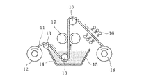
- FIG. 3 schematically shows an example of a configuration of a processing apparatus for making a resin porous body (hereinafter referred to as a band-shaped resin) conductive by making a resin molded body, which is a flat plate, long as a band, as an example of a practical manufacturing process.
- a processing apparatus for making a resin porous body hereinafter referred to as a band-shaped resin
- FIG. 3 schematically shows an example of a configuration of a processing apparatus for making a resin porous body (hereinafter referred to as a band-shaped resin) conductive by making a resin molded body, which is a flat plate, long as a band, as an example of a practical manufacturing process.
- this apparatus includes a supply bobbin 12 for supplying a belt-shaped resin 11, a tank 15 containing a conductive paint suspension 14, a pair of squeezing rolls 17 disposed above the tank 15, A plurality of hot air nozzles 16 provided opposite to the upper and lower surfaces of the belt-shaped resin 11 to be wound, and a winding bobbin 18 for winding the belt-shaped resin 11 after processing. Further, a deflector roll 13 for guiding the belt-shaped resin 11 is appropriately disposed.
- the strip-shaped resin 11 is unwound from the supply bobbin 12, guided by the deflector roll 13, and immersed in the suspension in the tank 15.
- the strip-shaped resin 11 immersed in the suspension 14 in the tank 15 changes its direction upward and travels between the squeeze rolls 17 above the liquid level of the suspension 14. At this time, the distance between the squeezing rolls 17 is smaller than the thickness of the strip-shaped resin 11, and the strip-shaped resin 11 is compressed. Therefore, the excess suspension impregnated in the belt-shaped resin 11 is squeezed out and returned to the tank 15.
- the strip-shaped resin 11 changes the traveling direction again.
- the suspension dispersion medium and the like are removed by hot air jetted by the hot air nozzle 16 composed of a plurality of nozzles, and the belt-like resin 11 is wound around the winding bobbin 18 after sufficiently drying.
- the temperature of the hot air ejected from the hot air nozzle 16 is preferably in the range of 40 ° C to 80 ° C.
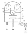
- FIG. 4 shows an overview of a direct current sputtering film forming apparatus.
- the DC sputtering deposition apparatus is in electrical and thermal contact with a chamber 100 that maintains a vacuum and a reduced pressure state, a cathode 106 and a target 105 that are cooled by a refrigerant, and a strip-shaped resin 101 on which a conductive layer is formed.
- the first drum functions as an anode, but is connected to the ground, and glow discharge plasma is generated by applying a DC voltage to the cathode.
- the chamber 100 is provided with an exhaust system 107 for evacuating the system, a gas piping system 108 for introducing an inert gas (for example, argon (Ar) gas) for generating plasma, and the like.
- an inert gas for example, argon (Ar) gas
- a protection plate 109 is installed so that plasma is not generated except in the portion of the first drum that faces the cathode.
- a shutter 110 is provided between the first drum and the cathode. The shutter 110 is closed at the start of glow discharge, and impurities on the target surface can be removed. During actual film formation, the shutter 110 is opened.
- the material is preferably a metal having high thermal conductivity such as copper.
- the temperature of the surface of the first drum is controlled so that thermal decomposition of the strip-shaped resin 101 is suppressed.
- the temperature of the surface of the first drum is also affected by the thickness of the strip-shaped resin 101 and the thickness of the metal film to be formed. That is, if the strip-shaped resin 101 is thick, the thermal conductivity is deteriorated, so the surface temperature of the first drum needs to be further lowered. If a thick metal film is to be formed, the film formation time becomes longer, and the time for the strip-shaped resin 101 to be exposed to plasma becomes longer. Therefore, the temperature of the first drum needs to be lowered.
- the inside of the chamber 100 is once evacuated to 10 ⁇ 4 Pa. Thereafter, Ar gas is introduced into the chamber 100 until the pressure reaches 1 Pa to 10 2 Pa. After the inside of the chamber reaches a certain pressure, a predetermined DC voltage is applied between the anode and the cathode to generate plasma by glow discharge. This DC voltage is usually adjusted to about several hundred volts to about 5 kV. The generated current value is about 10 ⁇ 1 to 10 2 A / m 2 , and the film formation rate can be increased by setting this current value high.
- a metal film is formed on the belt-shaped resin 101 by gasifying the raw material from the target by the generated plasma.
- the film thickness of the metal film at the surface position of the strip-shaped resin 101 having a flat plate shape is 10 ⁇ m, it takes about 1 to 3 hours to form the metal film with the cathode of the first drum. It moves on the opposing surface. Thereby, a metal film is formed on one surface of the belt-like resin 101.
- the belt-shaped resin 101 After the formation of the metal film on one surface of the belt-shaped resin 101 is completed, the belt-shaped resin 101 is rewinded, the surface on which the film is not formed is turned outside, and the metal film is formed again in the same manner as described above. Thus, a band-shaped metal structure in which a metal film is formed on the band-shaped resin molded body is created.
- the strip-shaped metal structure is heated to thermally decompose and remove the resin molded body.
- the heating condition may be air or an inert atmosphere such as nitrogen gas.
- the heating temperature may be equal to or higher than the thermal decomposition temperature of polyurethane or melamine resin as the material of the resin molded body, but is usually 400 ° C. or higher and 650 ° C. or lower. When the temperature exceeds 650 ° C., the oxidation of the metal film is promoted.
- Example 1 A porous metal body made of aluminum is prepared.
- the film forming apparatus shown in FIG. 4 is used.
- the distance between the target and the first drum is set to 10 cm.
- An aluminum plate is used for the target.
- polyurethane having a foamed thickness of 1 mm, a width of 10 cm, and an average pore diameter of 300 ⁇ m is used.
- Carbon is applied to the resin molded body. Carbon particles having an average particle size of 0.1 ⁇ m to 0.3 ⁇ m are used.
- the thickness of the carbon coating layer is about 1 ⁇ m.
- the surface temperature of the first drum is cooled to ⁇ 10 ° C. by circulating the fluorinated inert liquid cooled by the cooling device.
- the belt-shaped resin is moved at a constant speed while being in close contact with the first drum by roll-to-roll.
- Ar gas is controlled in the chamber so that the pressure becomes 1 Pa.
- a glow discharge plasma is generated by applying a DC voltage of 1 kV between the anode and the cathode.
- the current value at this time is about 2A.
- the surface temperature of the belt-like resin is 75 ° C. as measured by a radiation thermometer.
- the feeding speed of the belt-shaped resin was set to a speed for moving the half surface of the first drum (diameter: 50 cm) facing the cathode in 2 hours.
- the belt-shaped resin is re-rolled, the surface on which the film is not formed is turned outside, and the metal film is formed again in the same manner as described above.
- the obtained metal structure is heated at 500 ° C. for 15 minutes in the air to remove the resin molded body.
- the thickness of the obtained porous aluminum body is 1 mm, the thickness of the aluminum film at the surface position is 15 ⁇ m, and the thickness of the central aluminum film in the thickness direction is 12 ⁇ m.
- the compression test of the obtained aluminum porous body is performed. The aluminum porous body is cut into a 10 cm square and compressed to half the thickness in the thickness direction. No cracks occur in the aluminum skeleton constituting the aluminum porous body. Further, the difference in the average pore diameter after compression between the surface layer of the porous aluminum body and the central portion in the thickness direction is suppressed to about 90%.
- a nickel porous body is produced in the same manner as in Example 1.
- the thickness of the nickel film at the surface position of the obtained nickel porous body is 15 ⁇ m, and the thickness of the nickel film at the center in the thickness direction is 12 ⁇ m.
- the compression test of the obtained nickel porous body is performed. A nickel porous body is cut into a 10 cm square and compressed to half the thickness in the thickness direction. The nickel skeleton constituting the nickel porous body is not cracked. Further, the difference in the average pore diameter after compression between the surface layer of the nickel porous body and the central portion in the thickness direction is suppressed to about 90%.
- a porous aluminum body is produced in the same manner as in Example 1 except that the first drum is not cooled.
- the thickness of the obtained aluminum porous body is thinner than the initial thickness of the resin molded body, and the pore size distribution also varies widely.
- the compression test of the obtained aluminum porous body is performed.
- the aluminum porous body is cut into a 10 cm square and compressed to half the thickness in the thickness direction. It can be seen that the aluminum skeleton constituting the aluminum porous body is cracked and cut, resulting in embrittlement.
- porous metal body produced according to the present invention can be suitably used as a porous metal body in applications such as various filters and battery electrodes.
Abstract
The present invention provides a process for producing a porous metal body (such as a porous aluminum body) which is composed of a dense skeleton that has fewer pinholes and which is rarely contaminated with nitride or other impurities and is therefore not susceptible to embrittlement. This process comprises: employing, as a substrate, a flat plate composed of a resin-made skeleton having a three-dimensional network structure; forming a conductive layer on the surface of the resin-made skeleton; forming a metal film on the conductive layer by direct-current sputtering while bringing the plate into thermal contact with a drum cooled with a coolant; and removing the resin-made skeleton by heating after the formation of the metal film to produce a porous metal body.
Description
本発明は、金属のスパッタリング法により樹脂表面に金属膜を形成して金属多孔体を製造する方法に関し、特に各種フィルタや電池用電極などの用途に好適に用いることができる金属多孔体とその製造方法に関する。
The present invention relates to a method for producing a metal porous body by forming a metal film on a resin surface by a metal sputtering method, and in particular, a metal porous body that can be suitably used for applications such as various filters and battery electrodes, and the production thereof. Regarding the method.
三次元網目構造を有する金属多孔体は、各種フィルタ、触媒担体、電池用電極など多方面に用いられている。例えばニッケルからなるセルメット(住友電気工業(株)製:登録商標)がニッケル水素電池やニッケルカドミウム電池等の電池の電極材料として使用されている。セルメットは連通気孔を有する金属多孔体であり、金属不織布など他の多孔体に比べて気孔率が高い(90%以上)という特徴がある。これは発泡ウレタン等の連通気孔を有する多孔体樹脂の骨格表面にニッケル層を形成した後、熱処理して発泡樹脂成形体を分解し、さらにニッケルを還元処理することで得られる。ニッケル層の形成は、発泡樹脂成形体の骨格表面にカーボン粉末等を塗布して導電化処理した後、電気めっきによってニッケルを析出させることで行われる。
Metal porous bodies having a three-dimensional network structure are used in various fields such as various filters, catalyst carriers, and battery electrodes. For example, cermet made of nickel (manufactured by Sumitomo Electric Industries, Ltd .: registered trademark) is used as an electrode material for batteries such as nickel metal hydride batteries and nickel cadmium batteries. Celmet is a metal porous body having continuous air holes, and has a feature of high porosity (90% or more) compared to other porous bodies such as a metal nonwoven fabric. This can be obtained by forming a nickel layer on the surface of the porous resin skeleton having continuous air holes such as urethane foam, then heat-treating it to decompose the foamed resin molding, and further reducing the nickel. The formation of the nickel layer is performed by depositing nickel by electroplating after applying carbon powder or the like to the surface of the skeleton of the foamed resin molded body and conducting a conductive treatment.
又、アルミニウムは導電性、耐腐食性、軽量などの優れた特徴がある。電池用途では、例えば、リチウムイオン電池の正極として、アルミニウム箔の表面にコバルト酸リチウム等の活物質を塗布したものが使用されている。正極の容量を向上するためには、アルミニウムを多孔体にして表面積を大きくし、アルミニウム内部にも活物質を充填することが考えられる。そうすると電極を厚くしても活物質を利用でき、単位面積当たりの活物質利用率が向上するからである。
Aluminum also has excellent features such as conductivity, corrosion resistance, and light weight. In battery applications, for example, a positive electrode of a lithium ion battery in which an active material such as lithium cobaltate is applied to the surface of an aluminum foil is used. In order to improve the capacity of the positive electrode, it is conceivable that aluminum is made porous to increase the surface area and the aluminum is filled with an active material. This is because the active material can be used even if the electrode is thickened, and the active material utilization rate per unit area is improved.
アルミニウム多孔体の製造方法として、特許文献1には、内部連通空間を有する三次元網状のプラスチック基体にアークイオンプレーティング法によりアルミニウムの蒸着処理を施して、2~20μmの金属アルミニウム層を形成する方法が記載されている。又、特許文献2には、三次元網目状構造を有する発泡樹脂成形体の骨格にアルミニウムの融点以下で共晶合金を形成する金属(銅等)による皮膜を形成した後、アルミニウムペーストを塗布し、非酸化性雰囲気下で550℃以上750℃以下の温度で熱処理をすることで有機成分(発泡樹脂)の消失及びアルミニウム粉末の焼結を行い(焼結法)、金属多孔体を得る方法が記載されている。
As a method for producing a porous aluminum body, Patent Document 1 discloses that a metal aluminum layer having a thickness of 2 to 20 μm is formed by subjecting a three-dimensional net-like plastic substrate having an internal communication space to aluminum vapor deposition by an arc ion plating method. A method is described. In Patent Document 2, a film made of a metal (such as copper) that forms a eutectic alloy below the melting point of aluminum is formed on the skeleton of a foamed resin molding having a three-dimensional network structure, and then an aluminum paste is applied. There is a method of obtaining a porous metal body by performing a heat treatment at a temperature of 550 ° C. or more and 750 ° C. or less in a non-oxidizing atmosphere to eliminate organic components (foamed resin) and to sinter aluminum powder (sintering method). Are listed.
アークイオンプレーティング法等の気相堆積法では、焼結法等と比較して、不純物が少なく、純度の高い金属膜が形成されることは知られている。又、ピンホール等の欠陥も少なく、緻密な膜を得ることができる。
It is known that a vapor phase deposition method such as an arc ion plating method forms a metal film with less impurities and higher purity than a sintering method or the like. In addition, a dense film with few defects such as pinholes can be obtained.
しかし、気相堆積法は平板な基体上への成膜には適しているが、多孔体の微細孔の内部への成膜は困難となっている。ここにおいて、1Pa~102Pa程度の比較的高い圧力下で成膜を行うスパッタリング法は、10-4Pa程度の高真空度で成膜する真空蒸着法に比べて、平均自由工程が短いため、回り込みが起きやすく、陰になっている部分にも比較的成膜しやすい手法として知られている。
However, the vapor deposition method is suitable for forming a film on a flat substrate, but it is difficult to form a film inside the fine pores of the porous body. Here, the sputtering method in which film formation is performed under a relatively high pressure of about 1 Pa to 10 2 Pa has a shorter mean free process than the vacuum evaporation method in which film formation is performed at a high vacuum level of about 10 −4 Pa. It is known as a technique that is easy to wrap around and relatively easy to form a film on the shadowed part.
一方、基体に樹脂を用いた場合、熱やプラズマの影響により、基体の一部で分解が起きる。特に、厚い膜を形成するために、長時間の成膜をした場合には、熱の影響が大きくなり、分解ガスの発生量は格段に増加する。そして、発生した分解ガスが成膜雰囲気中に放出されることにより、成膜時に、膜中にその成分が取り込まれることが起き、膜の純度に影響が出る。
On the other hand, when a resin is used for the substrate, decomposition occurs in part of the substrate due to the influence of heat and plasma. In particular, when a film is formed for a long time in order to form a thick film, the influence of heat becomes large, and the generation amount of decomposition gas increases remarkably. The generated decomposition gas is released into the film formation atmosphere, so that the components are taken into the film during film formation, which affects the purity of the film.
特に、プラズマを用いたアークイオンプレーティング法やスパッタリング法等では、分解ガスがプラズマ中でさらに分解され、化学結合に関わる電子が励起されて活性になるので、膜中に不純物として取り込まれやすくなる。
In particular, in the arc ion plating method or sputtering method using plasma, the decomposition gas is further decomposed in the plasma, and the electrons related to the chemical bond are excited and activated, so that they are easily taken in as impurities in the film. .
他方、基体となる樹脂は、膜形成後、加熱処理で分解除去するが、これにはポリウレタンもしくはメラミン樹脂(メラミン-ホルムアルデヒド樹脂)が適しており、樹脂基体にアルミニウムを形成した後に、除去する手法では同樹脂は不可欠となっている。
On the other hand, the base resin is decomposed and removed by heat treatment after film formation. For this purpose, polyurethane or melamine resin (melamine-formaldehyde resin) is suitable. A method of removing aluminum after forming the resin base. So the resin is indispensable.
しかし、ポリウレタン、及びメラミン樹脂は、熱分解しやすい特徴を有しているが故に、熱やプラズマの影響を受けやすく、膜形成時の分解ガスの放出量が多くなる。
However, since polyurethane and melamine resin have characteristics that are easily decomposed by heat, they are easily affected by heat and plasma, and the amount of decomposition gas released during film formation increases.
さらに、アルミニウム等の金属は酸化されやすく、反応性に富み、ポリウレタン、及びメラミン樹脂からの分解ガスと反応し、アルミニウム等の金属の窒化、酸化、炭化が起きて、脆化する。又、分解ガスの放出量を抑制する為に耐熱性の高い樹脂を基体とした場合には、基体を除去する際の加熱温度を高くする必要が出てきて、アルミニウム等の金属が酸化しやすくなる。その酸化を抑制する為には大気中の酸素混入を防止する必要があるが、その雰囲気調整に設備面の負担が大きくなる。
Furthermore, metals such as aluminum are easily oxidized and rich in reactivity, reacting with decomposition gas from polyurethane and melamine resin, and nitriding, oxidation, and carbonization of metals such as aluminum occur and become brittle. In addition, if the substrate is made of a resin having high heat resistance in order to suppress the release amount of decomposition gas, it is necessary to increase the heating temperature when removing the substrate, and metals such as aluminum are likely to be oxidized. Become. In order to suppress the oxidation, it is necessary to prevent oxygen from being mixed in the atmosphere, but the burden on the facility is increased in adjusting the atmosphere.
例えば、窒化物等の不純物が多いアルミニウム多孔体を、リチウム二次電池やリチウムイオンキャパシタ、及び電気二重層キャパシタ用の集電体に用いた場合、活物質等を詰めて、プレスする際に、アルミニウム多孔体を構成する骨格が折れやすくなり、活物質の保持性や集電性が損なわれる問題が発生する。
For example, when an aluminum porous body having a large amount of impurities such as nitride is used for a current collector for a lithium secondary battery, a lithium ion capacitor, and an electric double layer capacitor, the active material is packed and pressed. The skeleton constituting the aluminum porous body is likely to be broken, and there arises a problem that the retention of the active material and the current collecting property are impaired.
本発明は比較的ピンホール等がない緻密な骨格より形成される金属多孔体であって、窒化物等の不純物の混入が少なく、脆化が起きにくいアルミニウム多孔体等の金属多孔体の製造方法を提供することを目的とする。
The present invention relates to a method for producing a porous metal body such as an aluminum porous body that is formed from a dense skeleton that has relatively no pinholes and that is less likely to cause embrittlement and that is less contaminated with impurities such as nitrides. The purpose is to provide.
本発明は、樹脂により成り、三次元網状の骨格から形成される平板を基体とし、前記骨格の表面に導電層を形成する導電化処理工程と、前記平板を冷却用ドラムに熱的に接触させて、前記導電層上に金属膜を直流スパッタリング法により形成する成膜工程と、前記成膜工程後に、前記基体を加熱により除去する工程と、を備える金属多孔体の製造方法である。
The present invention provides a conductive treatment step in which a flat plate made of a resin and formed from a three-dimensional network skeleton is used as a base, and a conductive layer is formed on the surface of the skeleton, and the flat plate is brought into thermal contact with a cooling drum. A porous metal body manufacturing method comprising: a film forming step of forming a metal film on the conductive layer by a direct current sputtering method; and a step of removing the substrate by heating after the film forming step.
成膜工程に直流スパッタリング法を使用する事により、焼結法と比較して、ピンホールが少なく緻密で、純度の高い金属多孔体を得る事ができる。焼結法では、特段に加圧することなく、粉末粒子同士が緩く焼結される為、粒子間に隙間が形成されやすくなる。
By using the direct current sputtering method in the film forming process, it is possible to obtain a dense metal porous body with less pinholes and higher purity than the sintering method. In the sintering method, the powder particles are loosely sintered without any special pressure, so that a gap is easily formed between the particles.
スパッタリング法は非平衡プラズマであるグロー放電を使用している。このため、アーク放電を用いるアークイオンプレーティング法と比較して、アルゴンガス等のプラズマに関わる気体温度は低くなり、基体となる三次元網状の骨格を有する樹脂(以下、樹脂成形体と言う。)への熱的負担を小さくすることができ、樹脂成形体からの分解ガスの発生を抑制する事ができる。
The sputtering method uses glow discharge which is non-equilibrium plasma. For this reason, compared with the arc ion plating method using arc discharge, the gas temperature related to plasma such as argon gas is lowered, and a resin having a three-dimensional network skeleton serving as a substrate (hereinafter referred to as a resin molding). ) Can be reduced, and generation of decomposition gas from the resin molded product can be suppressed.
加えて、直流スパッタリング法では、アルゴンガス等のグロー放電プラズマにより生成した正イオンは主にターゲットに衝突し、樹脂成形体での逆スパッタリング現象が起きにくい為、交流を用いる高周波スパッタリング法と比較して、樹脂成形体へのプラズマの直接的な負担は軽減される。これにより、樹脂成形体からの分解ガスの発生を抑制する事ができる。
In addition, in the direct current sputtering method, positive ions generated by glow discharge plasma such as argon gas mainly collide with the target, and the reverse sputtering phenomenon in the resin molded body hardly occurs, so compared with the high frequency sputtering method using alternating current. Thus, the direct burden of plasma on the resin molding is reduced. Thereby, generation | occurrence | production of the decomposition gas from a resin molding can be suppressed.
さらに、本発明においては、前記成膜工程において、前記平板を冷却用ドラムに熱的に接触させて冷却することにより、樹脂成形体の熱的負担は大幅に軽減される。ここで、熱的に接触するとは、形状が平板となる樹脂成形体の表面、すなわち、樹脂成形体の厚み方向における上表面と下表面の何れかの面、と冷却用ドラムの表面とがほぼ全面に渡って接触し、熱が両者間を伝導する状態を示す。なお、樹脂成形体の表面の100%が冷却用ドラムに接触している必要はなく、樹脂成形体の表面の少なくとも75%以上、好ましくは90%以上が接触していれば良い。
Furthermore, in the present invention, in the film forming step, the thermal burden on the resin molded body is greatly reduced by cooling the flat plate by bringing it into thermal contact with a cooling drum. Here, the term “thermal contact” means that the surface of the resin molded body whose shape is a flat plate, that is, either the upper surface or the lower surface in the thickness direction of the resin molded body, and the surface of the cooling drum are almost the same. It is in contact over the entire surface and heat is conducted between them. It is not necessary that 100% of the surface of the resin molded body is in contact with the cooling drum, and at least 75% or more, preferably 90% or more of the surface of the resin molded body may be in contact.
以上により、金属膜の成膜工程において、基体となる樹脂の分解を抑制し、金属膜中への炭素、窒素、酸素の混入を抑制できる。
As described above, in the metal film formation process, decomposition of the resin serving as the substrate can be suppressed, and mixing of carbon, nitrogen, and oxygen into the metal film can be suppressed.
加えて、本発明においては、前記樹脂はポリウレタン樹脂又はメラミン樹脂の内の1種もしくは混合物が使用される。
In addition, in the present invention, one or a mixture of polyurethane resin and melamine resin is used as the resin.
これらの樹脂は熱分解性に優れるので、金属膜を形成後に、金属膜を必要以上に酸化させることなく、樹脂成形体を除去することができる。
Since these resins are excellent in thermal decomposability, the resin molded body can be removed after the metal film is formed without oxidizing the metal film more than necessary.
前記金属多孔体をアルミニウム多孔体とした時、本発明の効果は一層発現される。
When the metal porous body is an aluminum porous body, the effects of the present invention are further manifested.
本発明により得られる金属多孔体は、三次元網状の骨格から形成される連通気孔を有し、前記連通気孔の平均気孔径が100μm以上、500μm以下の金属多孔体であって、前記金属多孔体は平板形状をとり、前記平板形状の厚みが0.5mm以上、5mm以下であり、前記骨格は中空構造をとり、前記中空構造を形成する壁の厚みが10μm以上であり、前記平板形状の表面位置における前記壁の厚みに対する、前記平板形状の厚みの中心位置における前記壁の厚みが75%以上である、金属多孔体である。
The metal porous body obtained by the present invention is a metal porous body having continuous air holes formed from a three-dimensional network skeleton, and having an average pore diameter of 100 μm or more and 500 μm or less. Takes a flat plate shape, the flat plate has a thickness of 0.5 mm or more and 5 mm or less, the skeleton has a hollow structure, and the wall forming the hollow structure has a thickness of 10 μm or more, the flat plate surface It is a metal porous body whose thickness of the said wall in the center position of the said flat plate-shaped thickness is 75% or more with respect to the thickness of the said wall in a position.
本発明の金属多孔体は、平板形状をとるが、その平板形状の厚み方向の中央部での金属骨格の厚みは、平板形状の厚み方向の上下の表面位置での金属骨格の厚みより薄い。しかし、本発明の金属多孔体はその差が小さい特徴を有する。
The metal porous body of the present invention takes a flat plate shape, and the thickness of the metal skeleton at the center in the thickness direction of the flat plate shape is thinner than the thickness of the metal skeleton at the upper and lower surface positions in the thickness direction of the flat plate shape. However, the metal porous body of the present invention has a feature that the difference is small.
これにより、例えば、本発明による金属多孔体をアルミニウム多孔体とし、リチウム二次電池や電気二重層キャパシタの電極に用いた場合、電極の内外での電子伝導性の差異が小さくなり、集電特性の差異が小さくなる。又、これらの電極を製造する際には、活物質等をアルミニウム多孔体中に充填した後に、平板形状の厚み方向に圧縮することが通常なされるが、電極の内外での圧縮の度合いの差異が小さく、比較的均一な電極を形成することができる。これにより、電極の厚み方向の中央部で活物質等が詰まりすぎて、電解液等の浸透が悪くなり、充放電特性が悪くなることが抑制され得る。
Thereby, for example, when the porous metal body according to the present invention is an aluminum porous body and used as an electrode of a lithium secondary battery or an electric double layer capacitor, the difference in electron conductivity between the inside and outside of the electrode is reduced, and the current collecting characteristics The difference is smaller. Moreover, when manufacturing these electrodes, the active material or the like is usually packed in the aluminum porous body and then compressed in the thickness direction of the flat plate shape, but the difference in the degree of compression inside and outside the electrode And a relatively uniform electrode can be formed. Thereby, it can be suppressed that the active material or the like is clogged too much at the central portion in the thickness direction of the electrode, the penetration of the electrolytic solution or the like becomes worse, and the charge / discharge characteristics become worse.
本発明によれば、比較的ピンホール等がない緻密な骨格より形成される金属多孔体であって、窒化物等の不純物の混入が少なく、脆化が起きにくい金属多孔体を提供することができる。
According to the present invention, it is possible to provide a metal porous body formed from a dense skeleton relatively free of pinholes and the like, in which impurities such as nitrides are hardly mixed and brittleness hardly occurs. it can.
以下に、本発明の実施の形態について、金属多孔体の製造方法、及び本発明により製造された金属多孔体を、代表例として、適宜、図を参照して説明する。
Hereinafter, embodiments of the present invention will be described by using a method for producing a metal porous body and a metal porous body produced according to the present invention as representative examples with reference to the drawings as appropriate.
(金属多孔体の製造工程)
図1は、樹脂成形体1を芯材として、導電層2の形成後に、金属膜3を形成し、最後に芯材を除去して、金属多孔体を製造する様子を模式的に示したものである。図1により、製造工程全体の流れを説明する。
まず樹脂成形体1の準備を行う(図1(a))。
次に、樹脂成形体1の表面に薄く導電層2を形成する(図1(b))。この導電層2により、この後に続く、直流スパッタリング法による金属膜3の成膜を効率的に行うことができる。又、導電層2は金属膜3の形成において、樹脂成形体1がプラズマに直接的にさらされて分解するのを抑制する保護層としても機能することが可能となる。さらに、導電層2はその電子伝導性ゆえに熱伝導性が比較的高く、樹脂単体の時よりも樹脂成形体1の冷却能を高めることができ、金属膜3形成時の樹脂成形体の熱分解を抑制することができる。
続いて、直流スパッタリング法により樹脂成形体に金属膜を形成する(図1(c))。これで、樹脂成形体の表面に金属膜3が形成された金属構造体が得られる。
最後に、樹脂成形体1の除去を行う。樹脂成形体1を分解等して消失させることにより金属層のみが残った金属多孔体を得ることができる(図1(d))。以下各工程について順を追って説明する。 (Manufacturing process of metal porous body)
FIG. 1 schematically shows a state where a metal porous body is manufactured by forming a metal film 3 after forming aconductive layer 2 using a resin molded body 1 as a core, and finally removing the core. It is. The overall flow of the manufacturing process will be described with reference to FIG.
First, the resin moldedbody 1 is prepared (FIG. 1A).
Next, a thinconductive layer 2 is formed on the surface of the resin molded body 1 (FIG. 1B). With this conductive layer 2, the subsequent metal film 3 can be efficiently formed by DC sputtering. In addition, the conductive layer 2 can function as a protective layer that suppresses the resin molded body 1 from being decomposed by being directly exposed to plasma in the formation of the metal film 3. Furthermore, the conductive layer 2 has a relatively high thermal conductivity due to its electronic conductivity, and can improve the cooling ability of the resin molded body 1 compared to the case of a single resin, and the thermal decomposition of the resin molded body when forming the metal film 3 Can be suppressed.
Subsequently, a metal film is formed on the resin molded body by a direct current sputtering method (FIG. 1C). Thus, a metal structure in which the metal film 3 is formed on the surface of the resin molded body is obtained.
Finally, the resin moldedbody 1 is removed. A metal porous body in which only the metal layer remains can be obtained by disassembling the resin molded body 1 to disappear (FIG. 1 (d)). Hereinafter, each step will be described in order.
図1は、樹脂成形体1を芯材として、導電層2の形成後に、金属膜3を形成し、最後に芯材を除去して、金属多孔体を製造する様子を模式的に示したものである。図1により、製造工程全体の流れを説明する。
まず樹脂成形体1の準備を行う(図1(a))。
次に、樹脂成形体1の表面に薄く導電層2を形成する(図1(b))。この導電層2により、この後に続く、直流スパッタリング法による金属膜3の成膜を効率的に行うことができる。又、導電層2は金属膜3の形成において、樹脂成形体1がプラズマに直接的にさらされて分解するのを抑制する保護層としても機能することが可能となる。さらに、導電層2はその電子伝導性ゆえに熱伝導性が比較的高く、樹脂単体の時よりも樹脂成形体1の冷却能を高めることができ、金属膜3形成時の樹脂成形体の熱分解を抑制することができる。
続いて、直流スパッタリング法により樹脂成形体に金属膜を形成する(図1(c))。これで、樹脂成形体の表面に金属膜3が形成された金属構造体が得られる。
最後に、樹脂成形体1の除去を行う。樹脂成形体1を分解等して消失させることにより金属層のみが残った金属多孔体を得ることができる(図1(d))。以下各工程について順を追って説明する。 (Manufacturing process of metal porous body)
FIG. 1 schematically shows a state where a metal porous body is manufactured by forming a metal film 3 after forming a
First, the resin molded
Next, a thin
Subsequently, a metal film is formed on the resin molded body by a direct current sputtering method (FIG. 1C). Thus, a metal structure in which the metal film 3 is formed on the surface of the resin molded body is obtained.
Finally, the resin molded
(樹脂成形体の準備)
三次元網状の骨格により形成され連通気孔を有する多孔質の樹脂成形体を準備する。樹脂成形体としては、連続した気孔(連通気孔)を有するものであれば、任意の形状の樹脂成形体を選択できる。例えば、樹脂を発泡させて成形したものや、繊維状の樹脂を絡めて不織布のような形状を有するものが使用可能である。樹脂成形体の気孔率は80%~98%、気孔径は100μm~500μmとするのが好ましい。 (Preparation of resin molding)
A porous resin molded body formed of a three-dimensional network skeleton and having continuous air holes is prepared. As the resin molded body, a resin molded body having an arbitrary shape can be selected as long as it has continuous pores (continuous vent holes). For example, those formed by foaming a resin or those having a shape like a nonwoven fabric entangled with a fibrous resin can be used. The resin molded body preferably has a porosity of 80% to 98% and a pore diameter of 100 μm to 500 μm.
樹脂成形体の材質は、ポリウレタン、メラミン樹脂が好ましい。ここで、樹脂を発泡させた樹脂成形体においては、発泡ウレタン及び発泡メラミン樹脂は気孔率が高く、又、気孔の連通性があるとともに、熱分解性にも優れているため、樹脂成形体として好ましく使用できる。さらに、発泡ウレタンは、気孔の均一性や、気孔径の小さなものが得られ易い点で好ましい。
The material of the resin molding is preferably polyurethane or melamine resin. Here, in the resin molded body in which the resin is foamed, the foamed urethane and the foamed melamine resin have high porosity, and have excellent porosity and thermal decomposability. It can be preferably used. Further, urethane foam is preferable in terms of the uniformity of pores and the ease of obtaining a product having a small pore diameter.
樹脂成形体には発泡体製造過程での製泡剤や未反応モノマーなどの残留物があることが多く、洗浄処理を行うことが後の工程のために好ましい。樹脂成形体の例として、発泡ウレタンを前処理として洗浄処理したものを図2に示す。樹脂成形体が骨格として三次元的に網目を構成することで、全体として連続した気孔を構成している。発泡ウレタンの骨格はその延在方向に垂直な断面において略三角形状をなしている。ここで気孔率は、次式で定義される。
気孔率=(1-(多孔質材の重量[g]/(多孔質材の体積[cm3]×素材密度)))×100[%]
又、気孔径は、樹脂成形体表面を顕微鏡写真等で拡大し、1インチ(25.4mm)あたりの気孔数をセル数として計数して、平均気孔径=25.4mm/セル数として平均的な値を求める。 Resin moldings often have residues such as foaming agents and unreacted monomers in the foam production process, and it is preferable to perform a cleaning treatment for the subsequent steps. As an example of the resin molded product, FIG. 2 shows a product obtained by washing urethane foam as a pretreatment. The resin molded body forms a three-dimensional network as a skeleton, thereby forming continuous pores as a whole. The urethane skeleton has a substantially triangular shape in a cross section perpendicular to the extending direction. Here, the porosity is defined by the following equation.
Porosity = (1− (weight of porous material [g] / (volume of porous material [cm 3 ] × material density))) × 100 [%]
Also, the pore diameter is averaged by enlarging the resin molded body surface with a micrograph, etc., and counting the number of pores per inch (25.4 mm) as the number of cells, and the average pore diameter = 25.4 mm / cell number. Find the correct value.
(樹脂成形体表面への導電層形成)
樹脂成型体の表面に導電層を形成する。樹脂成形体の表面に導電性を有する層を設けることができる処理である限り特に制限はなく、無電解めっき法によるニッケル、銅等の導電性金属層の形成、蒸着法又はスパッタリング法によるアルミニウム等の導電性金属層の形成、さらにはカーボン等の導電性粒子を含有した導電性塗料の塗布等、任意の方法を選択できる。
導電層形成の例として、アルミニウムのスパッタリング法による導電層を形成する方法、及び導電性粒子としてカーボンを用いた塗料を樹脂成形体の表面に塗布・乾燥して導電層を形成する方法について以下に述べる。 (Conductive layer formation on the surface of resin molding)
A conductive layer is formed on the surface of the resin molding. There is no particular limitation as long as it is a treatment that can provide a conductive layer on the surface of the resin molded body. Formation of a conductive metal layer such as nickel and copper by electroless plating, aluminum by vapor deposition or sputtering, etc. Any method can be selected, such as the formation of the conductive metal layer and the application of a conductive paint containing conductive particles such as carbon.
As an example of forming the conductive layer, a method for forming a conductive layer by sputtering of aluminum and a method for forming a conductive layer by applying and drying a paint using carbon as conductive particles on the surface of a resin molded body are described below. State.
-スパッタリング法によるアルミニウム層の形成-
スパッタリング法によるアルミニウム層形成としては、アルミニウムをターゲットとする限り、限定的でなく、常法に従って行えばよい。例えば、基板ホルダーに樹脂成形体を取り付けた後、不活性ガスを導入しながら、ホルダーとターゲット(アルミニウム)との間に、高周波もしくは直流グロー放電によるプラズマを発生させることにより、イオン化した不活性ガスをアルミニウムに衝突させて、はじき飛ばされたアルミニウム粒子を樹脂成形体の表面に堆積することによってアルミニウム層を形成する。 -Formation of aluminum layer by sputtering-
The aluminum layer formation by the sputtering method is not limited as long as aluminum is used as a target, and may be performed according to a conventional method. For example, after attaching a resin molded body to a substrate holder, an inert gas is introduced into the substrate and a target (aluminum) while generating plasma by high-frequency or direct current glow discharge between the holder and the target (aluminum). The aluminum layer is formed by causing the aluminum particles to collide with aluminum and depositing the repelled aluminum particles on the surface of the resin molded body.
なお、スパッタリング法では、樹脂成形体が溶解しない温度下で行うことが好ましく、具体的には、100~200℃程度、好ましくは120~180℃程度で行えば良い。ここで、プラズマによる樹脂成形体の分解を抑制する観点から直流を用いたスパッタリング法が好ましいが、高周波を用いた場合であっても、印加電圧を制御することにより、プラズマによる分解を抑制することは可能である。
The sputtering method is preferably performed at a temperature at which the resin molded body does not dissolve, and specifically, it may be performed at about 100 to 200 ° C., preferably about 120 to 180 ° C. Here, a sputtering method using direct current is preferable from the viewpoint of suppressing the decomposition of the resin molded body by plasma, but even when a high frequency is used, the decomposition by the plasma can be suppressed by controlling the applied voltage. Is possible.
-カーボン塗布-
導電性塗料としてのカーボン塗料を準備する。カーボン塗料は、好ましくは、カーボン粒子、粘結剤、分散剤および分散媒を含む。カーボン粒子を均一に塗布するには、カーボン塗料が均一な懸濁状態を維持している必要がある。このため、当該カーボン塗料(以下、懸濁液と言う。)は、20℃~40℃に維持されていることが好ましい。その理由は、懸濁液の温度が20℃未満になった場合、均一な懸濁状態が崩れ、樹脂成形体の三次元網状をなす骨格の表面に粘結剤のみが集中して層を形成するからである。この場合、塗布されたカーボン粒子の層は剥離し易く、強固に密着した金属膜を形成し難い。 -Carbon coating-
Prepare carbon paint as conductive paint. The carbon paint preferably contains carbon particles, a binder, a dispersant, and a dispersion medium. In order to uniformly apply the carbon particles, the carbon paint needs to maintain a uniform suspended state. For this reason, the carbon paint (hereinafter referred to as suspension) is preferably maintained at 20 ° C. to 40 ° C. The reason is that when the temperature of the suspension is less than 20 ° C., the uniform suspension state is lost, and only the binder is concentrated on the surface of the three-dimensional network structure of the resin molding to form a layer. Because it does. In this case, the applied carbon particle layer is easy to peel off, and it is difficult to form a tightly adhered metal film.
一方、懸濁液の温度が40℃を越えた場合は、分散剤および分散媒の蒸発量が大きく、塗布処理時間の経過とともに懸濁液が濃縮されてカーボンの塗布量が変動しやすい。又、カーボン粒子の平均粒径は、粒度分布計にて測定して、0.01~5μmで、好ましくは0.01~0.5μmである。粒径が大きいと、樹脂成形体の空孔の目詰まりにつながり、その部分は金属膜が形成されなくなる。又、平滑な金属膜の形成を阻害する要因ともなる。他方、粒径が小さすぎると、十分な導電性を確保することが難しくなり、次工程の金属膜形成が円滑に行えなくなる。
On the other hand, when the temperature of the suspension exceeds 40 ° C., the evaporation amount of the dispersant and the dispersion medium is large, and the suspension is concentrated as the coating treatment time elapses, and the coating amount of carbon tends to fluctuate. The average particle size of the carbon particles is 0.01 to 5 μm, preferably 0.01 to 0.5 μm, as measured with a particle size distribution meter. When the particle size is large, the pores of the resin molded body are clogged, and a metal film is not formed at that portion. Moreover, it becomes a factor which inhibits formation of a smooth metal film. On the other hand, if the particle size is too small, it is difficult to ensure sufficient conductivity, and the metal film formation in the next process cannot be performed smoothly.
樹脂成形体へのカーボン粒子の塗布は、上記カーボン塗料に対象となる樹脂成形体を浸漬し、絞りと乾燥を行うことで可能である。図3は実用上の製造工程の一例として、平板である樹脂成形体を長くして帯状とした樹脂多孔体(以下、帯状樹脂と言う。)を導電化する処理装置の構成例を模式的に示す図である。図示の如くこの装置は、帯状樹脂11を供給するサプライボビン12と、導電性塗料の懸濁液14を収容した槽15と、槽15の上方に配置された1対の絞りロール17と、走行する帯状樹脂11の上下面に対向して設けられた複数の熱風ノズル16と、処理後の帯状樹脂11を巻き取る巻取りボビン18とを備えている。又、帯状樹脂11を案内するためのデフレクタロール13が適宜配置されている。
Application of the carbon particles to the resin molded body can be performed by immersing the target resin molded body in the carbon paint and performing squeezing and drying. FIG. 3 schematically shows an example of a configuration of a processing apparatus for making a resin porous body (hereinafter referred to as a band-shaped resin) conductive by making a resin molded body, which is a flat plate, long as a band, as an example of a practical manufacturing process. FIG. As shown in the figure, this apparatus includes a supply bobbin 12 for supplying a belt-shaped resin 11, a tank 15 containing a conductive paint suspension 14, a pair of squeezing rolls 17 disposed above the tank 15, A plurality of hot air nozzles 16 provided opposite to the upper and lower surfaces of the belt-shaped resin 11 to be wound, and a winding bobbin 18 for winding the belt-shaped resin 11 after processing. Further, a deflector roll 13 for guiding the belt-shaped resin 11 is appropriately disposed.
以上のように構成された装置において、帯状樹脂11は、サプライボビン12から巻き戻され、デフレクタロール13により案内されて、槽15内の懸濁液内に浸漬される。槽15内で懸濁液14に浸漬された帯状樹脂11は、上方に向きを変え、懸濁液14の液面上方の絞りロール17の間を走行する。このとき、絞りロール17の間隔は、帯状樹脂11の厚さよりも小さくなっており、帯状樹脂11は圧縮される。従って、帯状樹脂11に含浸された過剰な懸濁液は、絞り出されて槽15内に戻る。
In the apparatus configured as described above, the strip-shaped resin 11 is unwound from the supply bobbin 12, guided by the deflector roll 13, and immersed in the suspension in the tank 15. The strip-shaped resin 11 immersed in the suspension 14 in the tank 15 changes its direction upward and travels between the squeeze rolls 17 above the liquid level of the suspension 14. At this time, the distance between the squeezing rolls 17 is smaller than the thickness of the strip-shaped resin 11, and the strip-shaped resin 11 is compressed. Therefore, the excess suspension impregnated in the belt-shaped resin 11 is squeezed out and returned to the tank 15.
続いて、帯状樹脂11は、再び走行方向を変える。ここで、複数のノズルから構成された熱風ノズル16が噴射する熱風により懸濁液の分散媒等が除去され、充分に乾燥された上で帯状樹脂11は巻取りボビン18に巻き取られる。尚、熱風ノズル16の噴出する熱風の温度は40℃から80℃の範囲であることが好ましい。以上のような装置を用いると、自動的かつ連続的に導電層の形成を実施することができ、目詰まりのない網目構造を有し、且つ、均一な導電層を具備した骨格が形成されるので、次工程の直流スパッタリング法による金属膜の形成を円滑に行うことができる。
Subsequently, the strip-shaped resin 11 changes the traveling direction again. Here, the suspension dispersion medium and the like are removed by hot air jetted by the hot air nozzle 16 composed of a plurality of nozzles, and the belt-like resin 11 is wound around the winding bobbin 18 after sufficiently drying. The temperature of the hot air ejected from the hot air nozzle 16 is preferably in the range of 40 ° C to 80 ° C. When the apparatus as described above is used, the conductive layer can be formed automatically and continuously, and a skeleton having a network structure without clogging and having a uniform conductive layer is formed. Therefore, the metal film can be smoothly formed by the direct current sputtering method in the next step.
-金属膜の形成-
図4に直流スパッタリング法成膜装置の概観を示す。直流スパッタリング法成膜装置は、真空、減圧状態を保持するチャンバー100と、冷媒により冷却される陰極106及びターゲット105と、導電層を形成した帯状樹脂101と電気的及び熱的に接触し、陽極となる第1ドラム(冷却用ドラム)102と、ロールツーロール方式となる帯状樹脂101を巻き出す第2ドラム103及び帯状樹脂101を巻き取る第3ドラム104からなる。第1ドラムは陽極として機能するが、アースに接続され、陰極との間に直流電圧が印加されることによりグロー放電プラズマが発生する。なお、チャンバー100には系内を真空引きする排気系107と、プラズマを発生させるための不活性ガス(例えば、アルゴン(Ar)ガス)を導入するガス配管系108等が付設されている。第1ドラム102の近傍には、第1ドラムにおける陰極と対向する部分以外でプラズマが発生しない様に防御板109が設置されている。第1ドラムと陰極の間にはシャッター110が設けられ、グロー放電開始時には閉じた状態になり、ターゲット表面の不純物除去を行うことができる。実際の成膜時にはシャッター110は開の状態とする。 -Formation of metal film-
FIG. 4 shows an overview of a direct current sputtering film forming apparatus. The DC sputtering deposition apparatus is in electrical and thermal contact with achamber 100 that maintains a vacuum and a reduced pressure state, a cathode 106 and a target 105 that are cooled by a refrigerant, and a strip-shaped resin 101 on which a conductive layer is formed. A first drum (cooling drum) 102, a second drum 103 for unwinding the strip-shaped resin 101 in a roll-to-roll system, and a third drum 104 for winding the strip-shaped resin 101. The first drum functions as an anode, but is connected to the ground, and glow discharge plasma is generated by applying a DC voltage to the cathode. The chamber 100 is provided with an exhaust system 107 for evacuating the system, a gas piping system 108 for introducing an inert gas (for example, argon (Ar) gas) for generating plasma, and the like. In the vicinity of the first drum 102, a protection plate 109 is installed so that plasma is not generated except in the portion of the first drum that faces the cathode. A shutter 110 is provided between the first drum and the cathode. The shutter 110 is closed at the start of glow discharge, and impurities on the target surface can be removed. During actual film formation, the shutter 110 is opened.
図4に直流スパッタリング法成膜装置の概観を示す。直流スパッタリング法成膜装置は、真空、減圧状態を保持するチャンバー100と、冷媒により冷却される陰極106及びターゲット105と、導電層を形成した帯状樹脂101と電気的及び熱的に接触し、陽極となる第1ドラム(冷却用ドラム)102と、ロールツーロール方式となる帯状樹脂101を巻き出す第2ドラム103及び帯状樹脂101を巻き取る第3ドラム104からなる。第1ドラムは陽極として機能するが、アースに接続され、陰極との間に直流電圧が印加されることによりグロー放電プラズマが発生する。なお、チャンバー100には系内を真空引きする排気系107と、プラズマを発生させるための不活性ガス(例えば、アルゴン(Ar)ガス)を導入するガス配管系108等が付設されている。第1ドラム102の近傍には、第1ドラムにおける陰極と対向する部分以外でプラズマが発生しない様に防御板109が設置されている。第1ドラムと陰極の間にはシャッター110が設けられ、グロー放電開始時には閉じた状態になり、ターゲット表面の不純物除去を行うことができる。実際の成膜時にはシャッター110は開の状態とする。 -Formation of metal film-
FIG. 4 shows an overview of a direct current sputtering film forming apparatus. The DC sputtering deposition apparatus is in electrical and thermal contact with a
第1ドラムは水やフッ素系不活性液体(例えば、フロリナート等)の冷媒により冷却することが重要となる。そして、その材質は銅等の熱伝導性の高い金属が好ましく用いられる。第1ドラムの表面の温度は、帯状樹脂101の熱分解が抑制される様に制御される。第1ドラムの表面の温度は、帯状樹脂101の厚さや、形成しようとする金属膜の厚さにも影響される。すなわち、帯状樹脂101が厚いと、熱伝導性が悪くなるため、一層、第1ドラムの表面温度は下げる必要がある。又、厚い金属膜を形成しようとすると、成膜時間が長くなり、それだけプラズマに帯状樹脂101が曝される時間が長くなるので、第1ドラムの温度は下げる必要がある。
It is important to cool the first drum with a refrigerant such as water or a fluorine-based inert liquid (for example, fluorinate). The material is preferably a metal having high thermal conductivity such as copper. The temperature of the surface of the first drum is controlled so that thermal decomposition of the strip-shaped resin 101 is suppressed. The temperature of the surface of the first drum is also affected by the thickness of the strip-shaped resin 101 and the thickness of the metal film to be formed. That is, if the strip-shaped resin 101 is thick, the thermal conductivity is deteriorated, so the surface temperature of the first drum needs to be further lowered. If a thick metal film is to be formed, the film formation time becomes longer, and the time for the strip-shaped resin 101 to be exposed to plasma becomes longer. Therefore, the temperature of the first drum needs to be lowered.
成膜速度を上げるためには、陰極と陽極間に投入する電力を多くする必要がある。この場合でも、一層、第1ドラムの表面温度を低下させる必要がある。ここでは、帯状樹脂101の表面温度が100℃を超えない様に第1ドラムの表面温度を制御することが重要となる。
In order to increase the deposition rate, it is necessary to increase the electric power supplied between the cathode and the anode. Even in this case, it is necessary to further reduce the surface temperature of the first drum. Here, it is important to control the surface temperature of the first drum so that the surface temperature of the belt-like resin 101 does not exceed 100 ° C.
次に、金属膜の形成方法について説明する。チャンバー100内を10-4Paまで一旦真空引きする。その後、チャンバー100内にArガスを1Pa~102Paの圧力になるまで導入する。チャンバー内が一定の圧力になった後に、陽極と陰極の間に所定の直流電圧を印加して、グロー放電によるプラズマを発生させる。この直流電圧は通常数100V~5kV程度で調整される。発生する電流値は10-1~102A/m2程度となるが、この電流値を高く設定することにより、成膜速度を上げることができる。発生したプラズマによりターゲットから原料をガス化させることによって帯状樹脂101に金属膜を形成する。金属膜の成膜時間は、平板形状となる帯状樹脂101の表面位置での金属膜の膜厚を10μm厚とする場合には、1時間~3時間程度をかけて、第1ドラムの陰極と対抗する面上を移動することとなる。これにより、帯状樹脂101の片面への金属膜の形成を行う。
Next, a method for forming a metal film will be described. The inside of the chamber 100 is once evacuated to 10 −4 Pa. Thereafter, Ar gas is introduced into the chamber 100 until the pressure reaches 1 Pa to 10 2 Pa. After the inside of the chamber reaches a certain pressure, a predetermined DC voltage is applied between the anode and the cathode to generate plasma by glow discharge. This DC voltage is usually adjusted to about several hundred volts to about 5 kV. The generated current value is about 10 −1 to 10 2 A / m 2 , and the film formation rate can be increased by setting this current value high. A metal film is formed on the belt-shaped resin 101 by gasifying the raw material from the target by the generated plasma. When the film thickness of the metal film at the surface position of the strip-shaped resin 101 having a flat plate shape is 10 μm, it takes about 1 to 3 hours to form the metal film with the cathode of the first drum. It moves on the opposing surface. Thereby, a metal film is formed on one surface of the belt-like resin 101.
帯状樹脂101の片面への金属膜の形成が終了した後、帯状樹脂101の巻き替えを行い、成膜していない面を外側にし、上記と同様に、再度、金属膜の形成を行う。これにより、帯状の樹脂成形体上に金属膜を形成した帯状の金属構造体を作成する。
After the formation of the metal film on one surface of the belt-shaped resin 101 is completed, the belt-shaped resin 101 is rewinded, the surface on which the film is not formed is turned outside, and the metal film is formed again in the same manner as described above. Thus, a band-shaped metal structure in which a metal film is formed on the band-shaped resin molded body is created.
最後に、帯状の金属構造体を加熱して、樹脂成形体を熱分解させて除去する。この加熱条件としては、大気中であっても良く、又、窒素ガス中等の不活性雰囲気であっても良い。加熱温度は、樹脂成形体の材質のポリウレタンあるいはメラミン樹脂の熱分解温度以上であれば良いが、通常、400℃以上、650℃以下が良い。650℃を超えると金属膜の酸化が促進される。
Finally, the strip-shaped metal structure is heated to thermally decompose and remove the resin molded body. The heating condition may be air or an inert atmosphere such as nitrogen gas. The heating temperature may be equal to or higher than the thermal decomposition temperature of polyurethane or melamine resin as the material of the resin molded body, but is usually 400 ° C. or higher and 650 ° C. or lower. When the temperature exceeds 650 ° C., the oxidation of the metal film is promoted.
次に、本発明を実施例に基づいてさらに詳細に説明する。実施例は本発明の範囲を限定するものではない。
Next, the present invention will be described in more detail based on examples. The examples are not intended to limit the scope of the invention.
(実施例1)
アルミニウムによる金属多孔体を作製する。図4に示す成膜装置を使用する。ターゲットと第1ドラムとの距離は10cmに設定する。ターゲットにはアルミニウム製の板を用いる。樹脂成形体には、発泡させた厚みが1mmで、幅10cm、平均気孔径が300μmのポリウレタンを使用する。
この樹脂成形体にカーボンを塗布する。カーボン粒子の平均粒径が0.1μm~0.3μmのものを使用する。カーボン塗布層の厚みは、1μm程度とする。
冷却装置により冷却したフッ素系不活性液体を循環させて第1ドラムの表面温度を-10℃に冷却する。帯状樹脂をロールツーロールにて第1ドラムに密着させながら一定速度で移動させる。
チャンバー内にArガスを1Paの圧力になる様に制御する。さらに、陽極と陰極との間に1kVの直流電圧を印加して、グロー放電プラズマを発生させる。この時の電流値は2A程度となる。帯状樹脂の表面温度は放射温度計による測定で75℃である。帯状樹脂の送り速度は、第1ドラム(直径:50cm)における陰極と対向する半面を2時間で移動する速度とした。帯状樹脂の片面への金属膜の形成が終了した後、帯状樹脂の巻き替えを行い、成膜していない面を外側にし、上記と同様に、再度、金属膜の形成を行う。
得られた金属構造体を大気中にて500℃で15分間加熱して、樹脂成形体を除去する。得られたアルミニウム多孔体の厚みは1mmであり、その表面位置のアルミニウム膜の厚みは15μmであり、厚み方向における中央部のアルミニウム膜の厚みは12μmである。
得られたアルミニウム多孔体の圧縮試験を行う。アルミニウム多孔体を10cm角に切り出し、厚み方向に半分の厚みになるまで圧縮する。アルミニウム多孔体を構成するアルニウム骨格に割れが生じることはない。又、アルミニウム多孔体の表面層と厚み方向の中央部での圧縮後の平均気孔径の差異は90%程度に抑えられる。 (Example 1)
A porous metal body made of aluminum is prepared. The film forming apparatus shown in FIG. 4 is used. The distance between the target and the first drum is set to 10 cm. An aluminum plate is used for the target. For the resin molded body, polyurethane having a foamed thickness of 1 mm, a width of 10 cm, and an average pore diameter of 300 μm is used.
Carbon is applied to the resin molded body. Carbon particles having an average particle size of 0.1 μm to 0.3 μm are used. The thickness of the carbon coating layer is about 1 μm.
The surface temperature of the first drum is cooled to −10 ° C. by circulating the fluorinated inert liquid cooled by the cooling device. The belt-shaped resin is moved at a constant speed while being in close contact with the first drum by roll-to-roll.
Ar gas is controlled in the chamber so that the pressure becomes 1 Pa. Further, a glow discharge plasma is generated by applying a DC voltage of 1 kV between the anode and the cathode. The current value at this time is about 2A. The surface temperature of the belt-like resin is 75 ° C. as measured by a radiation thermometer. The feeding speed of the belt-shaped resin was set to a speed for moving the half surface of the first drum (diameter: 50 cm) facing the cathode in 2 hours. After the formation of the metal film on one side of the belt-shaped resin is completed, the belt-shaped resin is re-rolled, the surface on which the film is not formed is turned outside, and the metal film is formed again in the same manner as described above.
The obtained metal structure is heated at 500 ° C. for 15 minutes in the air to remove the resin molded body. The thickness of the obtained porous aluminum body is 1 mm, the thickness of the aluminum film at the surface position is 15 μm, and the thickness of the central aluminum film in the thickness direction is 12 μm.
The compression test of the obtained aluminum porous body is performed. The aluminum porous body is cut into a 10 cm square and compressed to half the thickness in the thickness direction. No cracks occur in the aluminum skeleton constituting the aluminum porous body. Further, the difference in the average pore diameter after compression between the surface layer of the porous aluminum body and the central portion in the thickness direction is suppressed to about 90%.
(実施例2)
(Example 2)
金属にニッケルを使用して、実施例1と同様に、ニッケル多孔体を作製する。
得られたニッケル多孔体の表面位置のニッケル膜の厚みは15μmであり、厚み方向における中央部のニッケル膜の厚みは12μmである。
得られたニッケル多孔体の圧縮試験を行う。ニッケル多孔体を10cm角に切り出し、厚み方向に半分の厚みになるまで圧縮する。ニッケル多孔体を構成するニッケル骨格に割れが生じることはない。又、ニッケル多孔体の表面層と厚み方向の中央部での圧縮後の平均気孔径の差異は90%程度に抑えられる。
(比較例1) Using nickel as the metal, a nickel porous body is produced in the same manner as in Example 1.
The thickness of the nickel film at the surface position of the obtained nickel porous body is 15 μm, and the thickness of the nickel film at the center in the thickness direction is 12 μm.
The compression test of the obtained nickel porous body is performed. A nickel porous body is cut into a 10 cm square and compressed to half the thickness in the thickness direction. The nickel skeleton constituting the nickel porous body is not cracked. Further, the difference in the average pore diameter after compression between the surface layer of the nickel porous body and the central portion in the thickness direction is suppressed to about 90%.
(Comparative Example 1)
第1ドラムを冷却しない点以外は、実施例1と同様にアルミニウム多孔体を作製する。
得られたアルミニウム多孔体の厚みは当初の樹脂成形体の厚みより薄くなっており、気孔径の分布もばらつきが大きくなる。
得られたアルミニウム多孔体の圧縮試験を行う。アルミニウム多孔体を10cm角に切り出し、厚み方向に半分の厚みになるまで圧縮する。アルミニウム多孔体を構成するアルニウム骨格に割れや切断が生じ、脆化していることが分かる。 A porous aluminum body is produced in the same manner as in Example 1 except that the first drum is not cooled.
The thickness of the obtained aluminum porous body is thinner than the initial thickness of the resin molded body, and the pore size distribution also varies widely.
The compression test of the obtained aluminum porous body is performed. The aluminum porous body is cut into a 10 cm square and compressed to half the thickness in the thickness direction. It can be seen that the aluminum skeleton constituting the aluminum porous body is cracked and cut, resulting in embrittlement.
本発明により製造された金属多孔体は、各種フィルタや電池用電極などの用途における金属多孔体として好適に用いることができる。
The porous metal body produced according to the present invention can be suitably used as a porous metal body in applications such as various filters and battery electrodes.
1 樹脂成形体
2 導電層
3 金属膜
11 帯状樹脂
12 サプライボビン
13 デフレクタロール
14 導電性塗料の懸濁液
15 槽
16 熱風ノズル
17 絞りロール
18 巻取りボビン
100 チャンバー
101 帯状樹脂
102 第1ドラム(冷却用ドラム)
103 第2ドラム
104 第3ドラム
105 ターゲット
106 陰極
107 排気系
108 ガス配管系
109 防御板
110 シャッター DESCRIPTION OFSYMBOLS 1 Resin molding 2 Conductive layer 3 Metal film 11 Band-shaped resin 12 Supply bobbin 13 Deflector roll 14 Conductive paint suspension 15 Tank 16 Hot air nozzle 17 Drawing roll 18 Winding bobbin 100 Chamber 101 Band-shaped resin 102 1st drum (cooling) Drum)
103Second drum 104 Third drum 105 Target 106 Cathode 107 Exhaust system 108 Gas piping system 109 Guard plate 110 Shutter
2 導電層
3 金属膜
11 帯状樹脂
12 サプライボビン
13 デフレクタロール
14 導電性塗料の懸濁液
15 槽
16 熱風ノズル
17 絞りロール
18 巻取りボビン
100 チャンバー
101 帯状樹脂
102 第1ドラム(冷却用ドラム)
103 第2ドラム
104 第3ドラム
105 ターゲット
106 陰極
107 排気系
108 ガス配管系
109 防御板
110 シャッター DESCRIPTION OF
103
Claims (4)
- 樹脂により成り、三次元網状の骨格から形成される平板を基体とし、
前記骨格の表面に導電層を形成する導電化処理工程と、
前記平板を冷却用ドラムに熱的に接触させて、前記導電層上に金属膜を直流スパッタリング法により形成する成膜工程と、
前記成膜工程後に、前記基体を加熱により除去する工程と、
を備える金属多孔体の製造方法。 Made of resin, with a base plate formed from a three-dimensional network skeleton,
A conductive treatment step of forming a conductive layer on the surface of the skeleton;
A film forming step of thermally contacting the flat plate with a cooling drum and forming a metal film on the conductive layer by a direct current sputtering method;
Removing the substrate by heating after the film-forming step;
A method for producing a porous metal body. - 前記樹脂がポリウレタン樹脂又はメラミン樹脂の内の1種もしくは混合物である請求項1に記載の金属多孔体の製造方法。 The method for producing a porous metal body according to claim 1, wherein the resin is one or a mixture of polyurethane resin and melamine resin.
- 前記金属多孔体がアルミニウム多孔体である請求項1又は2に記載の金属多孔体の製造方法。 The method for producing a porous metal body according to claim 1 or 2, wherein the porous metal body is an aluminum porous body.
- 三次元網状の骨格から形成される連通気孔を有し、前記連通気孔の平均気孔径が100μm以上、500μm以下の金属多孔体であって、
前記金属多孔体は平板形状をとり、前記平板形状の厚みが0.5mm以上、5mm以下であり、
前記骨格は中空構造をとり、前記中空構造を形成する壁の厚みが10μm以上であり、
前記平板形状の表面位置における前記壁の厚みに対する、前記平板形状の厚みの中心位置における前記壁の厚みが75%以上である、
金属多孔体。 A porous metal body having continuous air holes formed from a three-dimensional network skeleton, wherein the average air hole diameter of the continuous air holes is 100 μm or more and 500 μm or less,
The metal porous body takes a flat plate shape, and the thickness of the flat plate shape is 0.5 mm or more and 5 mm or less,
The skeleton has a hollow structure, and a wall forming the hollow structure has a thickness of 10 μm or more,
The wall thickness at the central position of the flat plate thickness is 75% or more with respect to the thickness of the wall at the flat plate surface position.
Metal porous body.
Applications Claiming Priority (2)
| Application Number | Priority Date | Filing Date | Title |
|---|---|---|---|
| JP2012146252A JP2015165036A (en) | 2012-06-29 | 2012-06-29 | Method of producing metal porous body, and metal porous body |
| JP2012-146252 | 2012-06-29 |
Publications (1)
| Publication Number | Publication Date |
|---|---|
| WO2014002777A1 true WO2014002777A1 (en) | 2014-01-03 |
Family
ID=49782939
Family Applications (1)
| Application Number | Title | Priority Date | Filing Date |
|---|---|---|---|
| PCT/JP2013/066293 WO2014002777A1 (en) | 2012-06-29 | 2013-06-13 | Process for producing porous metal body and porous metal body |
Country Status (2)
| Country | Link |
|---|---|
| JP (1) | JP2015165036A (en) |
| WO (1) | WO2014002777A1 (en) |
Cited By (2)
| Publication number | Priority date | Publication date | Assignee | Title |
|---|---|---|---|---|
| CN105039771A (en) * | 2015-02-25 | 2015-11-11 | 上海交通大学 | Preparation method and application of three-dimensional interpenetrating porous magnesium-based material |
| US11268187B2 (en) | 2018-03-16 | 2022-03-08 | Jiangsu Zhongtian Technology Co., Ltd. | Porous aluminum macroscopic body and fabrication system and method therefor |
Families Citing this family (1)
| Publication number | Priority date | Publication date | Assignee | Title |
|---|---|---|---|---|
| WO2020049851A1 (en) * | 2018-09-07 | 2020-03-12 | 富山住友電工株式会社 | Metal porous body, fuel cell, and production method for metal porous body |
Citations (1)
| Publication number | Priority date | Publication date | Assignee | Title |
|---|---|---|---|---|
| JPH0610077A (en) * | 1992-01-13 | 1994-01-18 | C Uyemura & Co Ltd | Production of aluminum porous body |
-
2012
- 2012-06-29 JP JP2012146252A patent/JP2015165036A/en active Pending
-
2013
- 2013-06-13 WO PCT/JP2013/066293 patent/WO2014002777A1/en active Application Filing
Patent Citations (1)
| Publication number | Priority date | Publication date | Assignee | Title |
|---|---|---|---|---|
| JPH0610077A (en) * | 1992-01-13 | 1994-01-18 | C Uyemura & Co Ltd | Production of aluminum porous body |
Cited By (2)
| Publication number | Priority date | Publication date | Assignee | Title |
|---|---|---|---|---|
| CN105039771A (en) * | 2015-02-25 | 2015-11-11 | 上海交通大学 | Preparation method and application of three-dimensional interpenetrating porous magnesium-based material |
| US11268187B2 (en) | 2018-03-16 | 2022-03-08 | Jiangsu Zhongtian Technology Co., Ltd. | Porous aluminum macroscopic body and fabrication system and method therefor |
Also Published As
| Publication number | Publication date |
|---|---|
| JP2015165036A (en) | 2015-09-17 |
Similar Documents
| Publication | Publication Date | Title |
|---|---|---|
| CN1114963C (en) | Process for preparing metallic porous body, electrody substrate for battery and process for preparing the same | |
| US20120295169A1 (en) | Air battery and electrode | |
| WO2011132538A1 (en) | Method for producing aluminum structure and aluminum structure | |
| WO2012096220A1 (en) | Process for production of aluminum structure, and aluminum structure | |
| WO2012165213A1 (en) | Porous metallic body, electrode material using same, and cell | |
| KR102032265B1 (en) | Method for producing porous copper for a negative electrode current collector of a lithium secondary battery, and porous copper produced therefrom, and a negative electrode current collector of a lithium secondary battery | |
| JP2012186160A (en) | Battery | |
| WO2011142338A1 (en) | Method of manufacturing aluminum structure, and aluminum structure | |
| JP5648588B2 (en) | Aluminum structure manufacturing method and aluminum structure | |
| JP2012255185A (en) | Manufacturing method and manufacturing apparatus for aluminum porous body | |
| WO2014002777A1 (en) | Process for producing porous metal body and porous metal body | |
| JPWO2011043026A1 (en) | Negative electrode for lithium ion secondary battery and lithium ion secondary battery | |
| WO2012036065A1 (en) | Method for producing aluminum structure and aluminum structure | |
| JP5704026B2 (en) | Method for manufacturing aluminum structure | |
| JP5692233B2 (en) | Aluminum structure manufacturing method and aluminum structure | |
| JP2011246779A (en) | Method of manufacturing aluminum structure and the aluminum structure | |
| JP2013194308A (en) | Porous metallic body, electrode material using the same, and battery | |
| JP2011014279A (en) | Positive electrode for nonaqueous electrolyte secondary battery and its manufacturing method | |
| JP4811681B2 (en) | Electrode current collector manufacturing method and manufacturing apparatus, and battery equipped with the current collector | |
| JP6331808B2 (en) | Method for producing porous aluminum body | |
| KR102096448B1 (en) | Method and apparatus for manufacturing copper foil coated with graphene | |
| KR101745552B1 (en) | A method for manufacturing catalyst electrode of fuel cell having nanoporous structure and catalyst electrode of fuel cell thereof | |
| JP2015083716A (en) | Electrode material containing aluminum structure, battery and electric double-layer capacitor using the same, and filtration filter and catalyst carrier using aluminum structure | |
| JP5488994B2 (en) | Aluminum structure manufacturing method and aluminum structure | |
| JP2012255187A (en) | Manufacturing method and manufacturing apparatus for aluminum porous body |
Legal Events
| Date | Code | Title | Description |
|---|---|---|---|
| 121 | Ep: the epo has been informed by wipo that ep was designated in this application |
Ref document number: 13810765 Country of ref document: EP Kind code of ref document: A1 |
|
| NENP | Non-entry into the national phase |
Ref country code: DE |
|
| 122 | Ep: pct application non-entry in european phase |
Ref document number: 13810765 Country of ref document: EP Kind code of ref document: A1 |
|
| NENP | Non-entry into the national phase |
Ref country code: JP |