WO2014002735A1 - 空気物理量検出装置 - Google Patents
空気物理量検出装置 Download PDFInfo
- Publication number
- WO2014002735A1 WO2014002735A1 PCT/JP2013/065911 JP2013065911W WO2014002735A1 WO 2014002735 A1 WO2014002735 A1 WO 2014002735A1 JP 2013065911 W JP2013065911 W JP 2013065911W WO 2014002735 A1 WO2014002735 A1 WO 2014002735A1
- Authority
- WO
- WIPO (PCT)
- Prior art keywords
- bypass passage
- detection device
- physical quantity
- quantity detection
- air
- Prior art date
- Legal status (The legal status is an assumption and is not a legal conclusion. Google has not performed a legal analysis and makes no representation as to the accuracy of the status listed.)
- Ceased
Links
Images


Classifications
-
- G—PHYSICS
- G01—MEASURING; TESTING
- G01F—MEASURING VOLUME, VOLUME FLOW, MASS FLOW OR LIQUID LEVEL; METERING BY VOLUME
- G01F1/00—Measuring the volume flow or mass flow of fluid or fluent solid material wherein the fluid passes through a meter in a continuous flow
- G01F1/68—Measuring the volume flow or mass flow of fluid or fluent solid material wherein the fluid passes through a meter in a continuous flow by using thermal effects
- G01F1/696—Circuits therefor, e.g. constant-current flow meters
- G01F1/6965—Circuits therefor, e.g. constant-current flow meters comprising means to store calibration data for flow signal calculation or correction
-
- F—MECHANICAL ENGINEERING; LIGHTING; HEATING; WEAPONS; BLASTING
- F02—COMBUSTION ENGINES; HOT-GAS OR COMBUSTION-PRODUCT ENGINE PLANTS
- F02D—CONTROLLING COMBUSTION ENGINES
- F02D41/00—Electrical control of supply of combustible mixture or its constituents
- F02D41/02—Circuit arrangements for generating control signals
- F02D41/18—Circuit arrangements for generating control signals by measuring intake air flow
-
- G—PHYSICS
- G01—MEASURING; TESTING
- G01F—MEASURING VOLUME, VOLUME FLOW, MASS FLOW OR LIQUID LEVEL; METERING BY VOLUME
- G01F1/00—Measuring the volume flow or mass flow of fluid or fluent solid material wherein the fluid passes through a meter in a continuous flow
- G01F1/68—Measuring the volume flow or mass flow of fluid or fluent solid material wherein the fluid passes through a meter in a continuous flow by using thermal effects
- G01F1/684—Structural arrangements; Mounting of elements, e.g. in relation to fluid flow
- G01F1/6842—Structural arrangements; Mounting of elements, e.g. in relation to fluid flow with means for influencing the fluid flow
-
- G—PHYSICS
- G01—MEASURING; TESTING
- G01F—MEASURING VOLUME, VOLUME FLOW, MASS FLOW OR LIQUID LEVEL; METERING BY VOLUME
- G01F5/00—Measuring a proportion of the volume flow
-
- G—PHYSICS
- G01—MEASURING; TESTING
- G01N—INVESTIGATING OR ANALYSING MATERIALS BY DETERMINING THEIR CHEMICAL OR PHYSICAL PROPERTIES
- G01N27/00—Investigating or analysing materials by the use of electric, electrochemical, or magnetic means
- G01N27/02—Investigating or analysing materials by the use of electric, electrochemical, or magnetic means by investigating impedance
- G01N27/04—Investigating or analysing materials by the use of electric, electrochemical, or magnetic means by investigating impedance by investigating resistance
- G01N27/12—Investigating or analysing materials by the use of electric, electrochemical, or magnetic means by investigating impedance by investigating resistance of a solid body in dependence upon absorption of a fluid; of a solid body in dependence upon reaction with a fluid, for detecting components in the fluid
- G01N27/121—Investigating or analysing materials by the use of electric, electrochemical, or magnetic means by investigating impedance by investigating resistance of a solid body in dependence upon absorption of a fluid; of a solid body in dependence upon reaction with a fluid, for detecting components in the fluid for determining moisture content, e.g. humidity, of the fluid
-
- F—MECHANICAL ENGINEERING; LIGHTING; HEATING; WEAPONS; BLASTING
- F02—COMBUSTION ENGINES; HOT-GAS OR COMBUSTION-PRODUCT ENGINE PLANTS
- F02D—CONTROLLING COMBUSTION ENGINES
- F02D2200/00—Input parameters for engine control
- F02D2200/02—Input parameters for engine control the parameters being related to the engine
- F02D2200/04—Engine intake system parameters
- F02D2200/0418—Air humidity
Definitions
- the present invention relates to an air physical quantity detection device related to intake air of an internal combustion engine.
- Patent Document 1 is provided with a second sub air passage that opens inside the sub air passage in which the air flow rate detecting element is mounted for the purpose of providing clean intake air to the integrated humidity detecting element. , It is disclosed that a humidity detection element is mounted in the second sub air passage, and a portion of the second sub passage where the humidity detection element is mounted is located outside the outer wall of the intake pipe component member. .
- Patent Document 1 by increasing the distance from the sub air passage to the humidity detection element, it becomes difficult for a pollutant or a water droplet to reach the humidity detection element, and the fouling resistance is improved. However, since the distance from the sub air passage to the humidity detecting element is increased, the air does not easily flow into the humidity detecting element, and it is difficult to ensure the air flow rate inside the second sub air passage. For this reason, Patent Document 1 has room for study on improving the responsiveness of the humidity detection element.
- An object of the present invention is to provide an air physical quantity detection device having high antifouling property and good humidity measurement accuracy.
- an air physical quantity detection device of the present invention includes a housing member integrally including an attachment portion to the intake pipe, a connector and a connector terminal member, and a part of fluid flowing in the intake pipe.
- an air physical quantity detection device having high antifouling property and good humidity measurement accuracy.
- a sensor mounting hole 3 is provided in a part of the intake pipe 2 constituting the main passage 1, and an air physical quantity detection device 5 is attached via a seal member 4.
- This air physical quantity detection device 5 is a device in which a humidity sensor 8 part and an air flow rate sensor 9 part are integrally assembled using a housing member 7 integrally molded with a connector 6 as a basic structure.
- the air flow rate sensor 9 is provided with a first bypass passage 10 for taking in part of the intake air flowing through the main passage 1, and the first bypass passage 10 includes a part of the housing member 7, a base member 11, Furthermore, it is formed using the first bypass component 12, and inside the first bypass passage 10, an air flow sensor element 13 for detecting the air flow rate, a temperature compensation element 14 for detecting the air flow rate, and a temperature sensor 15 are provided. Is implemented. These elements are connected to the air flow sensor electronic circuit board 18 via the terminal member 16 and the metal wire 17, and the air flow sensor electronic circuit board 18 and the air flow sensor connector terminal 19 are electrically connected by the metal wire 17. By connecting to, input / output via the connector 6 becomes possible.
- a humidity sensor electronic circuit board 21 having a humidity sensor element 20 is mounted on the housing member 7, and the humidity sensor electronic circuit board 21 and the humidity sensor connector terminal 22 are electrically connected by a metal wire 17.
- the coating member 23 is used to protect the surface of the humidity sensor electronic circuit board 21, and external input / output is performed through the same connector 6 as the air flow sensor 9.
- the housing member 7 is also configured with a second bypass passage 24 that houses the humidity sensor element 20, and is completely separated and independent from the first bypass passage 10.
- the air flow sensor element 13 When the air flow sensor element 13 is prevented from being polluted, a bent portion is formed in the first bypass passage 10 to centrifuge the pollutant and water droplets taken in with the air.
- the centrifugally contaminated pollutant may be in the second auxiliary air passage. Since it is sprayed directly to the entrance, the contaminated material flows into the second sub-passage 24, and the humidity detecting element may be easily contaminated.
- the humidity sensor 8 is not affected by the shape of the first bypass passage 10 or the shape of the entire air flow sensor 9. Integration is facilitated, and a highly versatile integrated structure that does not interfere with the performance and reliability of both sensors can be achieved. Therefore, it becomes possible to integrate the humidity detection device into various types of air flow measurement devices with the same technique, improving development and production efficiency, and providing stable humidity detection performance and reliability.
- the entire first bypass passage 10 is arranged in the middle of the intake pipe 2, whereas the second bypass passage 24 including the second bypass inlet 25 and the second bypass outlet 26 is It is arranged outside the intake pipe inner wall surface 27.
- the second bypass passage is formed by using the pressure difference between the high pressure portion generated when the air flowing through the main passage 1 collides with the front surface of the air flow sensor 9 and the low pressure portion generated near the rear end portion of the air flow sensor 9. Since the air flow can be generated inside 24, the second bypass inlet 25 is opened inside the mounting hole 3 of the sensor. With this configuration, the fouling resistance is further improved against fouling substances and water droplets flowing with air. Similarly, since the second bypass outlet 26 is also opened inside the sensor mounting hole 3, it has anti-fouling properties against engine oil mist or the like that flows backward from the engine side by convection after the engine is stopped. .
- both antifouling performance and measurement accuracy can be realized.
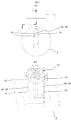
- FIG. 3 is a front structural view of the second embodiment of the present invention and its BB cross-sectional view.
- the air introduction groove 28 is formed in a front portion where the air flowing through the main passage 1 collides with a part of the housing member 7.
- the air introduction groove 28 has a concave shape provided on the side wall surface where the forward flow flowing through the intake pipe 2 of the housing member collides, and the side wall surface of the housing member 7 is formed by the air introduction groove 28 and its peripheral edge 30 (peripheral edge).
- the saucer shape is formed in.
- the tray shape provided in the housing member 7 is formed so as to be disposed in both the region disposed in the intake pipe of the housing member 7 and the region disposed in the mounting hole of the sensor.
- a second bypass inlet 25 is provided at the bottom of the air introduction groove 28 so as to open.
- the air introduction groove 28 is configured to be continuously connected to the second bypass passage 24, the flowing air can be received by the air introduction groove 28 and guided to the second bypass passage 24 as it is.
- the air introduction groove 28 can increase the pressure in the vicinity of the second bypass inlet 25 and increase the pressure difference between the second bypass inlet 25 and the second bypass outlet 26.
- the flow velocity inside the second bypass passage 24 can be further improved, so that the responsiveness of the humidity sensor 8 can be improved.
- the introduction groove 28 is provided perpendicular to the air flowing through the intake pipe, and dust or the like that collides with the introduction groove 28 adheres to the introduction groove and is difficult to reach the second bypass inlet. Antifouling property is improved. According to the second embodiment of the present invention, the antifouling performance and measurement accuracy of the humidity sensor 8 can be achieved at a higher level.
- FIG. 3 is a sectional view taken on line BB of a modification of the second embodiment of the present invention.
- an air introduction groove 28 is formed on the side wall surface on the backflow side of the housing member 7 similarly to the side wall surface on the forward flow side.
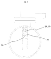
- FIG. 5 is a front structural view showing a third embodiment of the present invention and its CC cross-sectional view.
- a fouling trap surface 29 having a plurality of grooves in the direction perpendicular to the air flow direction was formed on the bottom surface of the air introduction groove 28.
- the third embodiment of the present invention it is possible to make it more difficult for contaminants such as dust to enter the second bypass passage 24, so that the stain resistance is improved and both the stain resistance and the measurement accuracy are achieved at a high level. be able to.
- FIG. 6 is a front structural view showing a fourth embodiment of the present invention.
- the edge 30 around the air introduction groove 28 was partly cut out to form an asymmetric shape, not a saucer shape. This is an effective means particularly when applied to an application where water droplets are highly likely to scatter.
- the water droplets adhere to the fouling trap surface 29, the water droplets flow along the grooves formed in the fouling trap surface 29, so that the water can be drained from the edge notch portion to the downstream side of the apparatus.
- the fouling performance against water droplets is particularly improved.
- both antifouling properties and measurement accuracy can be achieved at a higher level.
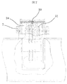
- FIG. 7 is a sectional view showing a fifth embodiment of the present invention.
- a trap groove 31 was formed on the inner wall surface of the second bypass passage 24 formed in the housing member 7. The contaminants that have not been captured by the means described up to FIG. 6 and have flowed into the second bypass passage 24 are trapped to prevent the contaminants from reaching the humidity sensor element 20.
- the trap groove 31 can disturb the air flowing inside the second bypass passage 24. If there is a distribution (unevenness) in the moisture content of the air flowing inside the second bypass passage 24, the correct humidity cannot be measured. When supplied to the sensor element 20, the measurement accuracy is also improved.
- this trap groove 31 is not suitable for the air flow rate sensor 9 in which the turbulence affects the measurement, in this configuration, the trap groove 31 is not installed in the first bypass passage 10 installed separately and independently. A trap groove 31 is formed only in the second bypass passage 24.
- the main purpose is a trapping structure for fouling substances. Therefore, an uneven shape that is not a groove is applied, or an adhesive material is placed on the inner wall surface of the second bypass passage 24. However, the same effect can be obtained.
- FIG. 8 is a sectional view showing a sixth embodiment of the present invention.
- a humidity / humidity sensor element 40 was mounted on the humidity sensor electronic circuit board 21 instead of the humidity sensor element 20, and a pressure sensor element 41 was also mounted in the vicinity thereof.
- a necessary physical quantity related to humidity is absolute humidity.
- the temperature signal output from the temperature / humidity sensor element 40 and the relative humidity signal are used.
- a pressure signal from the pressure sensor element 41 is required.
- the temperature information and pressure information at the point at which the relative humidity is measured are required.
- the pressure sensor element 41 is very much the temperature / humidity sensor element 40. It was necessary to be in the vicinity.
- the intake air 51 sucked from the air cleaner 50 passes through an intake manifold 55 having an intake pipe 2 into which the air physical quantity detection device 5 is inserted, an intake duct 52, a throttle body 53, and an injector 54 to which fuel is supplied, and then an engine cylinder. 56 is inhaled.
- the gas 57 generated in the engine cylinder 56 is discharged through the exhaust manifold 58.
- the control unit 62 that inputs the engine rotational speed signal output from the meter 61 and the like sequentially calculates these signals to obtain the optimum fuel injection amount and the optimum output torque, and uses the values to determine the injector 54 and the like.
- the throttle valve 63 is controlled.
Landscapes
- General Physics & Mathematics (AREA)
- Physics & Mathematics (AREA)
- Fluid Mechanics (AREA)
- Engineering & Computer Science (AREA)
- Chemical & Material Sciences (AREA)
- Health & Medical Sciences (AREA)
- Electrochemistry (AREA)
- Biochemistry (AREA)
- General Health & Medical Sciences (AREA)
- Life Sciences & Earth Sciences (AREA)
- Immunology (AREA)
- Pathology (AREA)
- Analytical Chemistry (AREA)
- Combustion & Propulsion (AREA)
- Mechanical Engineering (AREA)
- General Engineering & Computer Science (AREA)
- Chemical Kinetics & Catalysis (AREA)
- Measuring Volume Flow (AREA)
- Investigating Or Analyzing Materials By The Use Of Electric Means (AREA)
Abstract
本発明の目的は、耐汚損性が高く、湿度計測精度の良い空気物理量検出装置を提供することである。上記課題を解決する為に、本発明の空気物理量検出装置は、前記吸気管への取付部と、コネクタ及びコネクタ端子部材と、を一体で備えるハウジング部材と、前記吸気管内を流れる流体の一部を取り込む第一バイパス通路と、前記第一バイパス通路内に設けられる流量検出素子と、前記第一バイパス通路とは分離独立して設けられる第二バイパス通路と、前記第二バイパス通路内に設けられる湿度検出素子と、を備え、吸気管の内壁面よりも外側に位置することになる部分に前記第二検出素子を搭載し、前記第二バイパス通路の入口開口部は、前記ハウジング部材の順流側の側壁面に設けられていていることを特徴とする。
Description
本発明は内燃機関の吸入空気に係わる空気物理量検出装置に関する。
内燃機関の吸入空気の物理量検出技術として、空気流量測定装置と湿度検出装置を一体化した多機能型の空気流量測定装置がある。通常自動車の吸入空気はエアクリーナボックスが備えるエアフィルターエレメントによって大気中浮遊物を取り除いた後に取り込まれる構成となっている。しかし、エンジン出力低下や燃費の悪化を招くエアフィルターエレメントが作る大きな圧力損失は望まれないが故に、例えば排気ガス中に含まれる微細なカーボン等を捕らえるほどの濾紙が使用されることは無く、これら微細な大気浮遊物などは濾紙を通過してエンジンへ吸入される。また、エンジン停止後には高温に晒されたエンジンオイルが蒸気となってエアクリーナボックス側へ逆流してくることもあり、以上のようなことからエアクリーナボックス下流の空気は必ずしもきれいであるとは言えない。特許文献1には、一体化された湿度検出素子に対してクリーンな吸入空気を提供することを目的として、空気流量検出素子を実装する副空気通路の内部で開口する第二副空気通路を設け、該第二副空気通路の中に湿度検出素子を実装し、該第二副通路の湿度検出素子を実装する部分が吸気管構成部材外壁の外側に位置するようにすることが開示されている。
近年ではディーゼルエンジンの電子制御化も進んでおり、このディーゼルエンジンの汚損環境は、ガソリンエンジンシステムよりも更に厳しいものである。また、ガソリンエンジンにおいても、更なる流量検出精度を向上するために、汚損物による湿度検出素子の計測誤差を抑えることが望まれている。内燃機関への湿度検出装置の適用拡大や湿度検出装置の信頼性向上の要望に伴い、湿度検出装置に求められる耐汚損性を向上することが必要である。また、更なる低燃費化に向けて、湿度検出装置の計測誤差を低減するために応答性を向上させることが必要である。
特許文献1では、副空気通路から湿度検出素子までの距離を長くすることで、汚損物質や水滴などが湿度検出素子まで到達しにくくし、耐汚損性を向上させている。しかしながら、副空気通路から湿度検出素子までの距離を長くしているので、湿度検出素子まで空気が流れ込みにくい構成となっており、第二副空気通路内部の空気流速を確保することが難しい。そのため、特許文献1には、湿度検出素子の応答性を向上させることについて検討の余地がある。
本発明の目的は、耐汚損性が高く、湿度計測精度の良い空気物理量検出装置を提供することである。
上記課題を解決する為に、本発明の空気物理量検出装置は、前記吸気管への取付部と、コネクタ及びコネクタ端子部材と、を一体で備えるハウジング部材と、前記吸気管内を流れる流体の一部を取り込む第一バイパス通路と、前記第一バイパス通路内に設けられる流量検出素子と、前記第一バイパス通路とは分離独立して設けられる第二バイパス通路と、前記第二バイパス通路内に設けられる湿度検出素子と、を備え、吸気管の内壁面よりも外側に位置することになる部分に前記第二検出素子を搭載し、前記第二バイパス通路の入口開口部は、前記ハウジング部材の順流側の側壁面に設けられていていることを特徴とする。
本発明によれば、耐汚損性が高く、湿度計測精度の良い空気物理量検出装置を提供することができる。
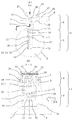
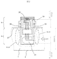
本発明の第一実施例を図1および図2を用いて説明する。
図1に示されるように、主通路1を構成する吸気管2には、その一部にセンサの装着穴3が設けられており、シール部材4を介して空気物理量検出装置5を取り付ける。この空気物理量検出装置5は、コネクタ6を一体で成型したハウジング部材7を基礎構造体として湿度センサ8部と空気流量センサ9部を一体で組立てた装置である。
空気流量センサ9には、主通路1を流れる吸入空気の一部を取り込むための第一バイパス通路10が設けられており、この第一バイパス通路10はハウジング部材7の一部とベース部材11、更には第一バイパス構成部材12を用いて形成され、第一バイパス通路10の内部には空気流量を検出する為の空気流量センサ素子13、空気流量検出時の温度補償用素子14、温度センサ15が実装される。これらの素子はターミナル部材16及び金属ワイヤ17を介して空気流量センサ用電子回路基板18と接続され、更に空気流量センサ用電子回路基板18と空気流量センサ用コネクタ端子19が金属ワイヤ17で電気的に接続されることで、コネクタ6を介しての入出力を可能とする。
湿度センサ8は、ハウジング部材7へ湿度センサ素子20を備えた湿度センサ用電子回路基板21を実装し、前記湿度センサ用電子回路基板21と湿度センサ用コネクタ端子22を金属ワイヤ17で電気的に接続した後にコーティング部材23を用いて湿度センサ用電子回路基板21の表面を保護することで形成され、空気流量センサ9と同じコネクタ6を介して外部との入出力を行う。ハウジング部材7には湿度センサ素子20を内装する第二バイパス通路24が併せて構成されており、第一バイパス通路10からは完全に分離独立して配置されている。
空気流量センサ素子13を汚損させないようにする際、空気と共に取り込んでしまった汚損物質や水滴を遠心分離させる曲がり部が第1バイパス通路10に形成される。しかし、曲がり部を有する第一バイパス通路10に第二バイパス通路の入口24が開口する場合、第二バイパス通路の入口24を設ける位置によっては、遠心分離された汚損物質が第二副空気通路の入り口に直接吹き付けられるので、かえって汚損物が第二副通路24内に流入してしまい、逆に湿度検出素子が汚れ易くなる虞がある。
上記構成によると、第二バイパス通路24は第一バイパス通路10から分離独立しているので、第一バイパス通路10の形状や、空気流量センサ9全体の形状に左右されずに湿度センサ8との一体化が容易になり、更に双方のセンサの性能や信頼性に対して互いに干渉しない汎用性の高い一体化構造とできる。そのため様々なタイプの空気流量測定装置へ同一テクニックで湿度検出装置を一体化できるようになり、開発、生産効率が向上すると共に、安定した湿度検出性能と信頼性を提供することができる。
図2に示されるように、第一バイパス通路10の全体が吸気管2の中ほどに配置されているのに対し、第二バイパス入口25と第二バイパス出口26を含む第二バイパス通路24は、吸気管内壁面27の外側に配置される。
汚損物質や水滴が重力に逆らう方向へは侵入し難い特性と、第二バイパス通路24をクランク状で且つ長く構成すると、万が一粒子の小さな大気中のゴミが流入してもその殆どがバイパス通路壁面に付着して湿度センサ素子20部へ到達し難くなる特性を組み合わせた構成であり、特に汚損や水滴付着に対して感度の高い湿度センサ8に有効な手段である。
また、本構成では主通路1を流れる空気が空気流量センサ9の正面に衝突することで生じる高圧部と空気流量センサ9の後端部付近に生じる低圧部の圧力差を用いて第二バイパス通路24内部に空気流を発生させることができる為、第二バイパス入口25はセンサの装着穴3の内部で開口している。本構成により、空気と共に流れてくる汚損物質や水滴などに対して更に耐汚損性が向上する。同様に、第二バイパス出口26もセンサの装着穴3の内部で開口している為、エンジンを停止した後にエンジン側から対流により逆流してくるエンジンオイルミスト等に対しても耐汚損性を持つ。
また、湿度計測用バイパス通路を吸気管外部へ配管することで、汚損物質がバイパス内部へ流れ込み難くなる。これにより耐汚損性能が向上すると共に、ハウジング正面に設けた空気導入溝で流れの動圧を受け、積極的にバイパス出口部との圧力差を作り出すことで湿度計測用バイパス内部の流速向上が達成できるので、湿度センサの応答性が向上する。
本発明の第一実施例によれば、耐汚損性能と計測精度の両立が実現できる。
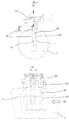
本発明の第二実施例について図3を用いて説明する。図3は本発明の第二実施例の正面構造図とそのB-B断面図である。
ハウジング部材7の一部で、且つ、主通路1を流れる空気が衝突する正面部に空気導入溝28を形成した。空気導入溝28はハウジング部材の吸気管2を流れる順流が衝突する側壁面に設けられた凹形状であり、この空気導入溝28とその周囲の縁30(周縁部)によりハウジング部材7の側壁面に受け皿形状が形成されている。該ハウジング部材7に設けられた受け皿形状は、ハウジング部材7の吸気管内に配置される領域と、センサの装着穴に配置される領域との両方に配置されるように形成されている。空気導入溝28の底部に第二バイパス入口25が開口するように設けられている。つまり、空気導入溝28は第二バイパス通路24と連続して繋がるように構成されているので、流れてきた空気をこの空気導入溝28で受けてそのまま第二バイパス通路24へ導くことができる。空気導入溝28により、第二バイパス入口25付近の圧力を大きくすることができ、第二バイパス入口25と第二バイパス出口26との圧力差を大きくすることができる。空気導入溝28を付加することで、第二バイパス通路24内部の流速をより向上させることができるので、湿度センサ8の応答性を向上することができる。さらに、導入溝28は吸気管を流れる空気に対して垂直に設けられており、導入溝28に衝突したダストなどは導入溝に付着し、第二バイパス入口まで到達しにくい構成となっているので対汚損性が向上する。本発明の第二実施例によれば、湿度センサ8の対汚損性能と計測精度をより高いレベルで両立できる。
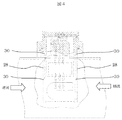
本発明の第二実施例の変形例について図4を用いて説明する。図3は本発明の第二実施例の変形例のB-B断面図である。
図3の構成に対し、ハウジング部材7の逆流側の側壁面にも、順流側の側壁面同様に空気導入溝28を形成する。エンジンの吸気脈動に起因して生じる逆流の湿度の計測する必要がある場合において、逆流の計測精度と対汚損性をより向上することができる。
本発明の第三実施例について図5を用いて説明する。図5は本発明の第三実施例を示す正面構造図とそのC-C断面図である。
空気導入溝28の底面部に空気の流れ方向に対して垂直な方向に複数の溝を持つ汚損トラップ面29を形成した。
吸気管2内部を流れる空気と共に流れてくる汚損物質や水滴はその殆どが下流へ流れるか、空気導入溝28の底部に付着するが、空気導入溝28へ到達した質量の軽い微小な塵やカーボン類は第二バイパス通路24の内部へ流入していく可能性がる。そこで、空気導入溝28の底面部に空気の流れ方向に対して垂直な方向に複数の溝を設けて、汚損物質を溝に付着させることで第二バイパス通路24内部へ入り込まないよう構成した。また同様に水滴も粘性があるので汚損トラップ面29の溝で引っ掛かり、第二バイパス通路24内部へ入らなくなる。
同一構造を下流側の空気導入溝28の底面部にも形成すると、エンジンを停止した後にエンジン側から対流により逆流してくるエンジンオイルミストや、エンジンの吸気脈動に起因して生じる逆流と共に流れてくる汚損物質に対しても同様な効果を得ることができる。
本発明の第三実施例によれば、よりダストなどの汚損物を第二バイパス通路24へ入りにくくすることができるので耐汚損性が向上し、高いレベルで耐汚損性と計測精度を両立することができる。
本発明の第四実施例について図6を用いて説明する。図6は本発明の第四実施例を示す正面構造図である。
空気導入溝28の周囲の縁30を一部切り欠き、受け皿形状ではない、非対称な形状に形成した。これは特に水滴が飛散してくる可能性の高いアプリケーションに適用すると有効な手段である。水滴が汚損トラップ面29に付着した場合、水滴は汚損トラップ面29に形成された溝に沿って流れていく特性を持つので、縁の切り欠き部分から本装置の下流側へ排水できるようになり、特に水滴に対する汚損性能が特に向上する。本発明の第四実施例によれば、対汚損性と計測精度をより高いレベルで両立することができる。
本発明の第五実施例について図7を用いて説明する。図7は本発明の第五実施例を示す断面図である。
ハウジング部材7に形成した第二バイパス通路24の内部壁面にトラップ溝31を形成した。図6までに記載した手段にて捕えきれずに第二バイパス通路24内部へ流入してきた汚損物質をトラップし、湿度センサ素子20へ汚損物質が到達することを防止する。
また、このトラップ溝31により、第二バイパス通路24内部を流れる空気を乱すことができる。第二バイパス通路24内部を流れる空気の水分量に分布(ムラ)があると、正しい湿度を計測することができなくなる為、トラップ溝31のような構造で空気を乱し、攪拌してから湿度センサ素子20へ供給すると計測精度も併せて向上する。尚、このトラップ溝31は流れの乱れが計測に影響する空気流量センサ9には適さないので、本構成では分離独立して設置された第一バイパス通路10にはトラップ溝31を設置せず、第二バイパス通路24のみにトラップ溝31を形成している。
また図7では溝形状を提案するが、主な目的は汚損物質のトラップ構造である為、溝ではない凹凸形状を適用したり、粘着性を持つ材料を第二バイパス通路24の内壁表面に設置しても同じような効果を得ることができる。
本発明の第六実施例について図8を用いて説明する。図8は本発明の第六実施例を示す断面図である。
湿度センサ用電子回路基板21上に湿度センサ素子20ではなく温湿度センサ素子40を実装し、更にその近傍に圧力センサ素子41を併せて実装した。本装置を自動車の内燃機関の制御に用いる場合、湿度に関連する必要な物理量は絶対湿度であり、この絶対湿度を得る為には、温湿度センサ素子40が出力する温度信号と相対湿度信号に加え、圧力センサ素子41からの圧力信号が必要になる。
更に絶対湿度として良好な精度を得る為には相対湿度を計測している正にその点での温度情報と圧力情報が必要であり、この為、圧力センサ素子41を温湿度センサ素子40のごく近傍に位置する必要があった。
電子燃料噴射方式の内燃機関に本発明の空気物理量検出装置5を適用した場合について図9を用いて説明する。
エアクリーナ50から吸入された吸入空気51は、空気物理量検出装置5が挿入される吸気管2,吸入ダクト52、スロットルボディ53及び燃料が供給されるインジェクタ54を備えたインテークマニホールド55を経て、エンジンシリンダ56に吸入される。一方、エンジンシリンダ56で発生したガス57は排気マニホールド58を経て排出される。
空気物理量検出装置5から出力される空気物理量信号、そしてスロットル角度センサ59から出力されるスロットルバルブ角度信号,排気マニホールド58に設けられた酸素濃度計60から出力される酸素濃度信号及び、エンジン回転速度計61から出力されるエンジン回転速度信号等、これらを入力するコントロールユニット62はこれらの信号を逐次演算して最適な燃料噴射量や最適な出力トルクを求め、その値を使って前記インジェクタ54やスロットルバルブ63を制御する。
1 主通路
2 吸気管
3 センサの装着穴
4 シール部材
5 空気物理量検出装置
6 コネクタ
7 ハウジング部材
8 湿度センサ
9 空気流量センサ
10 第一バイパス通路
11 ベース部材
12 第一バイパス構成部材
13 空気流量センサ素子
14 温度補償用素子
15 温度センサ
16 ターミナル部材
17 金属ワイヤ
18 空気流量センサ用電子回路基板
19 空気流量センサ用コネクタ端子
20 湿度センサ素子
21 湿度センサ用電子回路基板
22 湿度センサ用コネクタ端子
23 コーティング部材
24 第二バイパス通路
25 第二バイパス入口
26 第二バイパス出口
27 吸気管内壁面
28 空気導入溝
29 汚損トラップ面
30 周囲の縁
31 トラップ溝
40 温湿度センサ素子
41 圧力センサ素子
50 エアクリーナ
51 吸入空気
52 吸入ダクト
53 スロットルボディ
54 インジェクタ
55 インテークマニホールド
56 エンジンシリンダ
57 ガス
58 排気マニホールド
59 スロットル角度センサ
60 酸素濃度計
61 エンジン回転速度計
62 コントロールユニット
63 スロットルバルブ
Claims (9)
- 吸気管の挿入口に挿入することで、前記吸気管内を流れる空気の物理量を検出する吸気物理量検出装置において、
前記吸気管への取付部と、コネクタ及びコネクタ端子部材と、を一体で備えるハウジング部材と、
前記吸気管内を流れる流体の一部を取り込む第一バイパス通路と、
前記第一バイパス通路内に設けられる流量検出素子と、
前記第一バイパス通路とは分離独立して設けられる第二バイパス通路と、
前記第二バイパス通路内に設けられる湿度検出素子と、を備え、
吸気管の内壁面よりも外側に位置することになる部分に前記第二検出素子を搭載し、
前記第二バイパス通路の入口開口部は、前記ハウジング部材の順流側の側壁面に設けられていていることを特徴とする空気物理量検出装置。 - 請求項1に記載した空気物理量検出装置において、
前記第一バイパス通路の全体が吸気管の内部に位置し、前記第二バイパス通路の全体または少なくともその一部が吸気管の内壁よりも外側に位置していることを特徴とする空気物理量検出装置。 - 請求項2に記載した空気物理量検出装置において、
前記ハウジングの前記第二バイパス通路の一方の開口部が設けられる面に、前記第二バイパス通路の一方の開口部に連通する受け皿状の第一の溝が形成されていることを特徴とする空気物理量検出装置。 - 請求項3に記載した空気物理量検出装置において、
前記第二バイパス通路の他方の開口部が、前記ハウジングの前記第二バイパス通路の一方の開口部が設けられている面の反対側の面に開口していて、前記ハウジングの前記第二バイパス通路の他方の開口部が設けられる面に、前記第二バイパス通路の他方の開口部に連通する受け皿状の第二の溝が形成されていることを特徴とする空気物理量検出装置。 - 請求項4に記載した空気物理量検出装置において、
前記第一の溝と前記第二の溝の双方又は何れか一方の底面に、複数の凹凸が形成されていることを特徴とする空気物理量検出装置。 - 請求項5に記載した空気物理量検出装置において、
前記第一の溝及び前記第二の溝を構成する縁の一部を切り欠いたことを特徴とする空気物理量検出装置。 - 請求項1に記載した空気物理量検出装置において、
第二バイパスの内部壁面に凹凸が形成されていることを特徴とする空気物理量検出装置。 - 請求項1に記載した空気物理量検出装置において、
前記第二バイパス通路の内部に、湿度検出素子と、圧力検出素子を実装したことを特徴とする空気物理量検出装置。 - 取付部と、コネクタ及びコネクタ端子部材と、を一体で備えるハウジング部材と、
第一バイパス通路と、
前記第一バイパス通路内に設けられる流量検出素子と、
前記第一バイパス通路とは分離独立して設けられる第二バイパス通路と、
前記第二バイパス通路内に設けられる湿度検出素子と、を備え、
前記取り付け部よりも前記第一バイパス通路側を前記取り付け部の下側とし、前記湿度検出部を前記取り付け部よりも上側に設け、
前記第二バイパス通路の入口開口部は、前記ハウジング部材の側壁面の面積が小さいほうに設けられていていることを特徴とする空気物理量検出装置。
Applications Claiming Priority (2)
| Application Number | Priority Date | Filing Date | Title |
|---|---|---|---|
| JP2012-146288 | 2012-06-29 | ||
| JP2012146288A JP5675717B2 (ja) | 2012-06-29 | 2012-06-29 | 空気物理量検出装置 |
Publications (1)
| Publication Number | Publication Date |
|---|---|
| WO2014002735A1 true WO2014002735A1 (ja) | 2014-01-03 |
Family
ID=49782900
Family Applications (1)
| Application Number | Title | Priority Date | Filing Date |
|---|---|---|---|
| PCT/JP2013/065911 Ceased WO2014002735A1 (ja) | 2012-06-29 | 2013-06-10 | 空気物理量検出装置 |
Country Status (2)
| Country | Link |
|---|---|
| JP (1) | JP5675717B2 (ja) |
| WO (1) | WO2014002735A1 (ja) |
Cited By (1)
| Publication number | Priority date | Publication date | Assignee | Title |
|---|---|---|---|---|
| EP3176545A4 (en) * | 2014-07-30 | 2018-03-28 | Hitachi Automotive Systems, Ltd. | Physical-quantity detection device |
Families Citing this family (6)
| Publication number | Priority date | Publication date | Assignee | Title |
|---|---|---|---|---|
| JP6194852B2 (ja) * | 2014-06-06 | 2017-09-13 | 株式会社デンソー | 湿度検出機能付き空気流量測定装置 |
| JP5933782B1 (ja) * | 2015-03-16 | 2016-06-15 | 三菱電機株式会社 | 流量測定装置に一体に設けられた物理量測定装置および物理量測定方法 |
| US10444175B2 (en) | 2015-04-03 | 2019-10-15 | Denso Corporation | Measurement device |
| DE112017001130T5 (de) | 2016-05-23 | 2018-11-22 | Hitachi Automotive Systems, Ltd. | Feuchtemessvorrichtung |
| JP6919176B2 (ja) * | 2016-10-28 | 2021-08-18 | 株式会社デンソー | 空気物理量センサ |
| WO2018100854A1 (ja) * | 2016-11-30 | 2018-06-07 | 日立オートモティブシステムズ株式会社 | 空気流量測定装置 |
Citations (1)
| Publication number | Priority date | Publication date | Assignee | Title |
|---|---|---|---|---|
| JP2012083119A (ja) * | 2010-10-07 | 2012-04-26 | Hitachi Automotive Systems Ltd | センサの構造 |
Family Cites Families (4)
| Publication number | Priority date | Publication date | Assignee | Title |
|---|---|---|---|---|
| JP5178388B2 (ja) * | 2008-08-11 | 2013-04-10 | 日立オートモティブシステムズ株式会社 | 空気流量測定装置 |
| JP4929333B2 (ja) * | 2009-09-30 | 2012-05-09 | 日立オートモティブシステムズ株式会社 | センサの構造 |
| JP5396410B2 (ja) * | 2011-02-09 | 2014-01-22 | 日立オートモティブシステムズ株式会社 | センサの構造 |
| JP5557767B2 (ja) * | 2011-02-09 | 2014-07-23 | 日立オートモティブシステムズ株式会社 | センサの構造 |
-
2012
- 2012-06-29 JP JP2012146288A patent/JP5675717B2/ja active Active
-
2013
- 2013-06-10 WO PCT/JP2013/065911 patent/WO2014002735A1/ja not_active Ceased
Patent Citations (1)
| Publication number | Priority date | Publication date | Assignee | Title |
|---|---|---|---|---|
| JP2012083119A (ja) * | 2010-10-07 | 2012-04-26 | Hitachi Automotive Systems Ltd | センサの構造 |
Cited By (2)
| Publication number | Priority date | Publication date | Assignee | Title |
|---|---|---|---|---|
| EP3176545A4 (en) * | 2014-07-30 | 2018-03-28 | Hitachi Automotive Systems, Ltd. | Physical-quantity detection device |
| US10655991B2 (en) | 2014-07-30 | 2020-05-19 | Hitachi Automotive Systems, Ltd. | Physical-quantity detection device for intake air in an internal combustion engine |
Also Published As
| Publication number | Publication date |
|---|---|
| JP5675717B2 (ja) | 2015-02-25 |
| JP2014010026A (ja) | 2014-01-20 |
Similar Documents
| Publication | Publication Date | Title |
|---|---|---|
| JP5178388B2 (ja) | 空気流量測定装置 | |
| JP5675717B2 (ja) | 空気物理量検出装置 | |
| JP5396410B2 (ja) | センサの構造 | |
| CN102538867B (zh) | 传感器的结构 | |
| JP5049996B2 (ja) | 熱式流量測定装置 | |
| JP5557767B2 (ja) | センサの構造 | |
| US6851309B2 (en) | Device for determining at least one parameter of a flowing medium | |
| EP2056076B1 (en) | Heating resistor type air flow rate measuring device | |
| CN106415213B (zh) | 用于确定流过通道结构的流体介质的至少一个参数的传感器装置 | |
| JP5779471B2 (ja) | 湿度検出装置 | |
| CN104126105A (zh) | 用于检测流动流体介质的至少湿度的传感器装置 | |
| CN101319952A (zh) | 吸入空气流量测量装置 | |
| JP6208251B2 (ja) | 物理量計測装置 | |
| JP6069504B2 (ja) | 温湿度センサ | |
| JP2006047272A (ja) | 流量センサ | |
| KR20160016690A (ko) | 측정 채널을 통해 유동하는 유체 매체의 적어도 하나의 파라미터를 결정하기 위한 센서 | |
| JP2003161652A (ja) | 流量測定装置 |
Legal Events
| Date | Code | Title | Description |
|---|---|---|---|
| 121 | Ep: the epo has been informed by wipo that ep was designated in this application |
Ref document number: 13809799 Country of ref document: EP Kind code of ref document: A1 |
|
| NENP | Non-entry into the national phase in: |
Ref country code: DE |
|
| 122 | Ep: pct app. not ent. europ. phase |
Ref document number: 13809799 Country of ref document: EP Kind code of ref document: A1 |