WO2013190833A1 - Absorbent article and method of manufacturing absorbent article - Google Patents
Absorbent article and method of manufacturing absorbent article Download PDFInfo
- Publication number
- WO2013190833A1 WO2013190833A1 PCT/JP2013/003800 JP2013003800W WO2013190833A1 WO 2013190833 A1 WO2013190833 A1 WO 2013190833A1 JP 2013003800 W JP2013003800 W JP 2013003800W WO 2013190833 A1 WO2013190833 A1 WO 2013190833A1
- Authority
- WO
- WIPO (PCT)
- Prior art keywords
- region
- elastic member
- adhesive
- disposed
- absorber
- Prior art date
- Legal status (The legal status is an assumption and is not a legal conclusion. Google has not performed a legal analysis and makes no representation as to the accuracy of the status listed.)
- Ceased
Links
Images









Classifications
-
- A—HUMAN NECESSITIES
- A61—MEDICAL OR VETERINARY SCIENCE; HYGIENE
- A61F—FILTERS IMPLANTABLE INTO BLOOD VESSELS; PROSTHESES; DEVICES PROVIDING PATENCY TO, OR PREVENTING COLLAPSING OF, TUBULAR STRUCTURES OF THE BODY, e.g. STENTS; ORTHOPAEDIC, NURSING OR CONTRACEPTIVE DEVICES; FOMENTATION; TREATMENT OR PROTECTION OF EYES OR EARS; BANDAGES, DRESSINGS OR ABSORBENT PADS; FIRST-AID KITS
- A61F13/00—Bandages or dressings; Absorbent pads
- A61F13/15—Absorbent pads, e.g. sanitary towels, swabs or tampons for external or internal application to the body; Supporting or fastening means therefor; Tampon applicators
- A61F13/45—Absorbent pads, e.g. sanitary towels, swabs or tampons for external or internal application to the body; Supporting or fastening means therefor; Tampon applicators characterised by the shape
- A61F13/49—Absorbent pads, e.g. sanitary towels, swabs or tampons for external or internal application to the body; Supporting or fastening means therefor; Tampon applicators characterised by the shape specially adapted to be worn around the waist, e.g. diapers or nappies
- A61F13/49007—Form-fitting, self-adjusting disposable diapers
- A61F13/49009—Form-fitting, self-adjusting disposable diapers with elastic means
- A61F13/49017—Form-fitting, self-adjusting disposable diapers with elastic means the elastic means being located at the crotch region
-
- A—HUMAN NECESSITIES
- A61—MEDICAL OR VETERINARY SCIENCE; HYGIENE
- A61F—FILTERS IMPLANTABLE INTO BLOOD VESSELS; PROSTHESES; DEVICES PROVIDING PATENCY TO, OR PREVENTING COLLAPSING OF, TUBULAR STRUCTURES OF THE BODY, e.g. STENTS; ORTHOPAEDIC, NURSING OR CONTRACEPTIVE DEVICES; FOMENTATION; TREATMENT OR PROTECTION OF EYES OR EARS; BANDAGES, DRESSINGS OR ABSORBENT PADS; FIRST-AID KITS
- A61F13/00—Bandages or dressings; Absorbent pads
- A61F13/15—Absorbent pads, e.g. sanitary towels, swabs or tampons for external or internal application to the body; Supporting or fastening means therefor; Tampon applicators
- A61F13/45—Absorbent pads, e.g. sanitary towels, swabs or tampons for external or internal application to the body; Supporting or fastening means therefor; Tampon applicators characterised by the shape
- A61F13/49—Absorbent pads, e.g. sanitary towels, swabs or tampons for external or internal application to the body; Supporting or fastening means therefor; Tampon applicators characterised by the shape specially adapted to be worn around the waist, e.g. diapers or nappies
- A61F13/494—Absorbent pads, e.g. sanitary towels, swabs or tampons for external or internal application to the body; Supporting or fastening means therefor; Tampon applicators characterised by the shape specially adapted to be worn around the waist, e.g. diapers or nappies characterised by edge leakage prevention means
- A61F13/49406—Absorbent pads, e.g. sanitary towels, swabs or tampons for external or internal application to the body; Supporting or fastening means therefor; Tampon applicators characterised by the shape specially adapted to be worn around the waist, e.g. diapers or nappies characterised by edge leakage prevention means the edge leakage prevention means being at the crotch region
-
- A—HUMAN NECESSITIES
- A61—MEDICAL OR VETERINARY SCIENCE; HYGIENE
- A61F—FILTERS IMPLANTABLE INTO BLOOD VESSELS; PROSTHESES; DEVICES PROVIDING PATENCY TO, OR PREVENTING COLLAPSING OF, TUBULAR STRUCTURES OF THE BODY, e.g. STENTS; ORTHOPAEDIC, NURSING OR CONTRACEPTIVE DEVICES; FOMENTATION; TREATMENT OR PROTECTION OF EYES OR EARS; BANDAGES, DRESSINGS OR ABSORBENT PADS; FIRST-AID KITS
- A61F13/00—Bandages or dressings; Absorbent pads
- A61F13/15—Absorbent pads, e.g. sanitary towels, swabs or tampons for external or internal application to the body; Supporting or fastening means therefor; Tampon applicators
- A61F13/51—Absorbent pads, e.g. sanitary towels, swabs or tampons for external or internal application to the body; Supporting or fastening means therefor; Tampon applicators characterised by the outer layers of the pads
- A61F13/514—Backsheet, i.e. the impermeable cover or layer furthest from the skin
- A61F13/51456—Backsheet, i.e. the impermeable cover or layer furthest from the skin characterised by its properties
- A61F13/51464—Backsheet, i.e. the impermeable cover or layer furthest from the skin characterised by its properties being stretchable or elastomeric
-
- A—HUMAN NECESSITIES
- A61—MEDICAL OR VETERINARY SCIENCE; HYGIENE
- A61F—FILTERS IMPLANTABLE INTO BLOOD VESSELS; PROSTHESES; DEVICES PROVIDING PATENCY TO, OR PREVENTING COLLAPSING OF, TUBULAR STRUCTURES OF THE BODY, e.g. STENTS; ORTHOPAEDIC, NURSING OR CONTRACEPTIVE DEVICES; FOMENTATION; TREATMENT OR PROTECTION OF EYES OR EARS; BANDAGES, DRESSINGS OR ABSORBENT PADS; FIRST-AID KITS
- A61F13/00—Bandages or dressings; Absorbent pads
- A61F13/15—Absorbent pads, e.g. sanitary towels, swabs or tampons for external or internal application to the body; Supporting or fastening means therefor; Tampon applicators
- A61F13/53—Absorbent pads, e.g. sanitary towels, swabs or tampons for external or internal application to the body; Supporting or fastening means therefor; Tampon applicators characterised by the absorbing medium
- A61F13/531—Absorbent pads, e.g. sanitary towels, swabs or tampons for external or internal application to the body; Supporting or fastening means therefor; Tampon applicators characterised by the absorbing medium having a homogeneous composition through the thickness of the pad
- A61F13/532—Absorbent pads, e.g. sanitary towels, swabs or tampons for external or internal application to the body; Supporting or fastening means therefor; Tampon applicators characterised by the absorbing medium having a homogeneous composition through the thickness of the pad inhomogeneous in the plane of the pad
- A61F13/533—Absorbent pads, e.g. sanitary towels, swabs or tampons for external or internal application to the body; Supporting or fastening means therefor; Tampon applicators characterised by the absorbing medium having a homogeneous composition through the thickness of the pad inhomogeneous in the plane of the pad having discontinuous areas of compression
Definitions
- the present invention relates to an absorbent article and a method of manufacturing the absorbent article in which an elastic member is disposed between two sheet members in an expanded state.
- Patent Literature 1 there is disclosure of an absorbent article in which an expanded elastic member at the periphery of a leg hole opening unit is provided.
- the elastic member is disposed in an expanded state on a sheet so that a left side leg-holes elastic member and a right side leg-hole elastic member of the absorbent article are continuous to each other, and an unnecessary elastic member between the left side leg-holes elastic member and the right side leg-holes elastic member is cut.
- the thus manufactured absorbent article is an absorbent article in which the left side leg-holes elastic member and the right side leg-hole elastic member are discontinuous from each other.
- the inventor(s) has/have recognized that the above described absorption material might have the following problems. After an elastic member has been disposed in a continuously expanded state in the course of manufacture, if an attempt is made to cut the elastic member and subsequently discontinuously dispose the elastic member, a cut portion of an elastic member is released from in an expanded state and subsequently shrinks when the elastic member is cut. Therefore, an end of the elastic member moves to an inner side rather than the cut position in the expanded direction. If a length of movement of the end of this elastic member increases, the elastic member is not disposed in proximity to the cut portion, and a portion of sheet member adjacent to the cut portion does not shrink.
- an object of the present invention to provide an absorbent article and a method of manufacturing the absorbent article in which an elastic member in an expanded state is disposed between two sheet members and the sheet members are shrunk by the elastic member, the absorbent article being an absorbent article in which an intended region of the sheet member is shrunk by the elastic member while flexibility of the sheet members are retained.
- an absorbent article to be worn by a wearer such as a disposable diaper having a foreside and a backside and a crotch region connecting said frontside and said backside, comprising: an absorber having a longitudinal direction expanding to a foreside and a backside of the wearer, a widthwise direction perpendicular to the longitudinal direction, an inner direction for facing the wearer, and an outer direction opposite the inner direction; an exterior body disposed in an inner side or an outer side of the absorber and having a plurality of sheet members; an elastic member disposed between a first sheet member and a second sheet member that are included in the plurality of sheet members in a state in which the elastic member is expanded in at least one direction of the longitudinal direction and the widthwise direction; a first adhesive region including a region at least the elastic member is disposed and in which an adhesive is applied between the first sheet member and the second sheet member; a second adhesive region of which a part is disposed while overlapping on the first adhesive region and in which an adhesive is
- the present invention further provides a method of manufacturing an absorbent article which comprises an absorber having a longitudinal direction expanding to a foreside and a backside of a wearer, a widthwise direction perpendicular to the longitudinal direction, an inner direction for facing a wearer, and an outer direction opposite the inner direction,, an exterior body disposed in an inner side or an outer side of the absorber and having a plurality of sheet members; and an elastic member disposed between a first sheet member and a second sheet member that are included in the plurality of sheet members in a state in which the elastic member is expanded in at least one direction of the longitudinal direction and the widthwise direction, the method comprising the steps of: providing a first adhesive region by applying an adhesive to at least one face of the elastic member among a face of the elastic member side of the first sheet and a face on the elastic member side of the second sheet side; providing a second adhesive region by applying an adhesive to at least one end of the sheet member among an end of the first sheet member of a face of the elastic member side and an end of the second
- the present invention further provides an absorbent article comprising: an absorbent main body having an absorber having a longitudinal direction extending to a body foreside and a body backside of a wearer, a widthwise direction orthogonal to the longitudinal direction, an inner direction oriented to the wearer, and an outer direction oriented to an opposite side to the inner direction; an exterior body disposed in an outer direction than the absorbent main body; a crotch region adapted to be in contact with a crotch of the wearer; a front waistline region disposed forward of the crotch region; and a back waistline region disposed backward of the crotch region, wherein the absorber has one pair of curving units lying at both outer side in a widthwise direction than a center in a widthwise direction of the absorber and formed so that allows the absorber to curve in a convex shape in the outer direction, wherein a plurality of elastic members are disposed at the exterior body, wherein the plurality of elastic members respectively have a linear portion formed in
- Fig. 1 is a perspective schematic view of a disposable diaper 1 according to first embodiment.
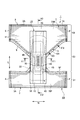
- Fig. 2 is an exploded plan view of the disposable diaper 1.
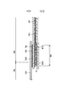
- Fig. 3 is a widthwise cross-sectional view of the disposable diaper 1 along the X1-X'1 line shown in Fig. 2.
- Fig. 4 is a crosswise cross-sectional view of the disposable diaper 1 along the X2-X'2 line shown in Fig. 2.
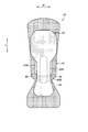
- Fig. 5 is a plan view of an absorber according to at least one embodiment.
- Fig. 6 is a cross-sectional view along the X1-X'1 line that schematically illustrates the wearing state of the disposable diaper 1 according to at least one embodiment.
- Fig. 7 is a view schematically showing the steps of manufacturing the absorbent article according to the first embodiment.
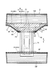
- Fig. 8 is a view schematically showing a first adhesive region and a second adhesive region.
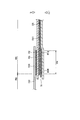
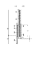
- Fig. 9 is a schematic sectional view of an exterior body taken along the X3-X'3 line shown in Fig. 2.
- Fig. 10 is an exploded plan view of a disposable diaper according to the first modification embodiment.
- Fig. 11 is a schematic sectional view of an exterior body taken along the X4-X'4 line shown in Fig. 10.
- Fig. 12 is a schematic sectional view of a disposable diaper according the second modification embodiment.
- Fig. 13 is an exploded plan view of a disposable diaper according to the third modification embodiment.
- Fig. 14 is a schematic sectional view with reference to the line X3-X'3 shown in Fig.
- Fig. 15 is a schematic sectional view with reference to the line X3-X'3 shown in Fig. 2 of a disposable diaper according to the fifth modification embodiment.
- Fig. 16 is an exploded plan view of a disposable diaper according to the sixth modification embodiment.
- Fig. 17 is a cross-sectional view along the X5-X'5 line and the X6-X'6 line that illustrates the expanded state of the disposable diaper 1 according to the sixth modification embodiment.
- Fig. 18 is a cross-sectional view along the X5-X'5 line and the X6-X'6 line that illustrates the natural state of the disposable diaper 1 according to the sixth modification embodiment.
- Fig. 19 is an exploded plan view of a disposable diaper according to the seventh modification embodiment.
- FIG. 1 is a perspective schematic view of a disposable diaper 1 that configures the disposable diaper in present embodiment.
- Fig. 2 is an exploded plan view of the disposable diaper 1 according to at least one embodiment.
- Fig. 3 is a widthwise cross-sectional view of the disposable diaper 1 along the X1-X'1 line shown in Fig. 2.
- Fig. 4 is a crosswise cross-sectional view of the disposable diaper 1 along the X2-X'2 line shown in Fig. 2.
- the disposable diaper 1 is a pants-type disposable diaper.
- a disposable diaper 1 has: a longitudinal direction L expanding to a body foreside and a body backside of a wearer; a widthwise direction orthogonal to the longitudinal direction L; and a thickness direction T having an inner direction IN oriented to the wearer and an outer direction OUT oriented to an opposite side to the inner direction.
- a front waistline region S1 which corresponds to a front waistline of a wearer
- a back waistline region S2 which corresponds to a back waistline of the wearer
- a crotch region S3 which corresponds to a crotch of the wearer, and is positioned between the front waistline region S1 and the back waistline region S2.
- a front waistline edge portion 4 lying outside in one widthwise direction of the disposable diaper 1 in the front waistline region S1 is joined with a back waistline edge portion 6 lying outside in one widthwise direction of the back waistline region S2, and a front waistline edge portion 4' lying outside in the other widthwise direction is joined with a back waistline edge portion 6' lying outside in the other widthwise direction, whereby the disposable diaper 1 is formed in the pants type.
- a joint unit 11 of which the respective edge portion s are joined with each other is formed, and the crotch region S3 is a region inner side of the joint unit 11 in the longitudinal direction.
- a waistline opening unit 8 disposed so as to surround the wearer's waistline and a pair of leg hole opening unit 9 disposed so as to surround the wearer's leg in a state in which it is formed in the shape of a pant.
- the disposable diaper 1 includes: an absorbent main body 1A including a topsheet 10, an absorber 40, and an absorbent backsheet 30 or the like; and an exterior body 1B including a foreside exterior topsheet 70F, a backside exterior topsheet 70R, and an exterior backsheet or the like, and these constituent elements are joined to each other by an adhesive or thermal fusion bonding or the like.
- the exterior body 1B includes: a foreside exterior topsheet 70F and a backside exterior topsheet 70R, each of which serves as an exterior topsheet; a foreside exterior backsheet 80F and a backside exterior backsheet 80R each of which serves as exterior backsheets; and an exterior center sheet 100, and constitutes an exterior portion of the disposable diaper 1.
- the exterior body 1B lies in an outer direction OUT more significantly than the absorbent main body 1A including the absorber 40, and is disposed on a non-skin contact surface of the disposable diaper.
- the foreside exterior topsheet 70F is disposed across the front waistline region S1 and the crotch region S3.
- the backside exterior topsheet 70R is disposed across the back waistline region S2 and the crotch region S3.
- the foreside exterior topsheet 70F and the backside exterior topsheet 70R are spaced from each other in the longitudinal direction, and are disposed in the thickness direction between the foreside exterior backsheet 80F or the backside exterior backsheet 80R and the absorbent main body 1A.
- the foreside exterior topsheet 70F and the backside exterior topsheet 70R can be formed by an air-through nonwoven cloth, a spun bond nonwoven cloth, an SMS nonwoven cloth, or a water-resistive film.
- the exterior topsheet according to at least one embodiment is constituted of an SMS nonwoven having a basis weight of 15 g/ m 2 of polypropylene.
- the foreside exterior backsheet 80F and the backside exterior backsheet 80R lie outside when the disposable diaper is worn. Namely, these backsheets are disposed on a side on which they are spaced from the wearer's skin.
- the foreside exterior backsheet 80F is disposed across the front waistline region S1 and the crotch region S3.
- the backside exterior backsheet 80R is disposed across the back waistline region S2 and the crotch region S3.
- the foreside exterior backsheet 80F and the backside exterior backsheet 80R are spaced from each other in the longitudinal direction.
- a front end of the foreside exterior backsheet 80F and a rear end of the backside exterior backsheet 80R are folded back to the skin-contact face side, and are disposed so as to envelope the front end of the foreside exterior topsheet 70F and the rear end of the backside exterior topsheet 70R.
- the foreside exterior topsheet 70F and the foreside exterior backsheet 80F constitute a foreside exterior body
- the backside exterior topsheet 70R and the backside exterior backsheet 80R constitute a backside exterior body.
- the exterior backsheet can be formed by an air-through nonwoven cloth, a spun bond nonwoven cloth, an SMS nonwoven cloth, or a water-resistive film.
- the exterior backsheet according to at least one embodiment is constituted of an SMS nonwoven having a basis weight of 18 g/ m 2 of polypropylene.
- the exterior center sheet 100 couples the foreside exterior body and the backside exterior body to each other. Specifically, the exterior center sheet 100 lies between a rear end of the foreside exterior topsheet 70F and a front end of the backside exterior topsheet 70R and the backside exterior backsheet 80R in the longitudinal direction, and lines between the foreside exterior topsheet 70F and the absorbent backsheet 30 or an elastic member covering sheet 43 and between the backside exterior topsheet 70R and the absorbent backsheet 30 or the elastic member covering sheet 43 in the thickness direction.
- a part of the exterior center sheet 100 is constituted so as to be disposed in an overlapped region to be described later, and functions as a third sheet member.
- the third sheet member is part of the plurality of sheet members.
- the exterior center sheet 100 is provided to thereby able to connect the foreside exterior body and the backside exterior body to each other. Therefore, in an aspect in which the exterior topsheet and the exterior backsheet are spaced from each other in the longitudinal direction, exposure of the absorbent main body 1A can be prevented. Further, in the course of manufacture, in a state in which the foreside exterior body and the backside exterior body are coupled to each other, a leg hole opening unit is formed, and adhesive bonding with the absorbent main body 1A is possible.
- the exterior center sheet 100 can be formed by an air-through nonwoven cloth, a spun bond nonwoven cloth, an SMS nonwoven cloth, or a water-resistive film.
- the exterior center sheet 100 according to at least one embodiment is constituted of a spun bond nonwoven having a basis weight of 19 g/ m 2 of polypropylene.
- the absorbent main body 1A includes a topsheet 10, an auxiliary sheet 15, an absorbent backsheet, and a leakage preventing unit, and is disposed is provided closer to the skin contact surface than the exterior body 1B.
- the topsheet 10 is a sheet that forms the skin contact surface that can be in direct contact with the skin of the wearer.
- the topsheet 10 is provided closer to the skin contact surface than the absorber 40.
- the topsheet 10 is formed by a liquid-permeable sheet, such as a hydrophilic nonwoven cloth and woven cloth, an aperture plastic film, or an aperture hydrophobic nonwoven cloth.
- the topsheet 10 according to at least one embodiment is formed of a hydrophilic spun bond nonwoven cloth having a basis weight of 23 g/ m 2 of polypropylene.
- a basis weight of the member which configures the disposable diaper can be measured by a following measurement method, for example.
- the package body is opened to spread out the disposable diaper folded over therein, thereby measuring a thickness and an area of a portion which is to be measured in a basis weight.
- the portion to be measured in a basis weight is cut out of the disposable diaper, and a weight of the cut-out portion is measured.
- portions other than the member are removed, and a weight of the absorber is measured. Based on a weight of the member and an area of the portion to be measured in a basis weight, a basis weight is calculated.
- An auxiliary sheet 15 is joined with the non-skin contact surface side of the topsheet 10.
- the auxiliary sheet 15 is disposed between the topsheet 10 and the absorber 40. Providing the auxiliary sheet 15 makes it possible to increase the speed at which the bodily fluid is absorbed, and makes it possible to prevent reversal of the bodily fluid after absorption.
- the auxiliary sheet 15 is made of, for example, an air-through nonwoven cloth, a porous film, or the like.
- the auxiliary sheet 15 of at least one embodiment is formed of 30 g/ m 2 (hydrophilic) air-through nonwoven cloth.
- the topsheet 10 and the auxiliary sheet 15 are joined by adhesive.
- the absorber 40 is joined between a composite sheet on which the topsheet 10 and the auxiliary sheet 15 are joined with each other and the absorbent backsheet 30 by a hot melt adhesive.
- the hot melt adhesive is respectively applied to the composite sheet and the backsheet, and is applied at a respective one of the basis weights of 5 g/m 2 and 8 g/m 2 by a spiral coating method, for example.
- the absorber 40 is formed of a mixed powder of ground pulp, highly absorbent polymer, and the like.
- the absorber 40 is configured using a first layer 41 disposed closer to the non-skin contact surface with the wearer and a second layer 42 overlapping with the first layer 41 and disposed closer to the skin contact surface of the wearer (see Fig.5) .
- the first layer 41 of the absorber 40 has a central slit 45 and sideslit46 expanding in the longitudinal direction.
- the central slit 45 formed in the center of the first layer in the widthwise direction W.
- a pair of side slits 46 is formed outboard of the central slit 45 in the widthwise direction.
- the disposable diaper 1 has a central elastic member 44 disposed so as to overlap a central slit 45.
- This diaper is constituted with these elastic members or slits or the like formed on the absorber 40 so that the absorber 40 is curved when the disposable diaper 1 is worn.
- the central elastic member 44 and the central slit 45 constitute a curving unit formed so that the absorber can be curved in a convex shape toward an inner direction.
- a side slit 46 is formed so that the slit can be curved in a convex shape toward an outer direction. It is to be noted that a structure of the absorber will be described later in detail.
- the absorbent backsheet 30 is provided at a non-skin contact surface side of the absorber 40.
- the absorbent backsheet 30 is formed of a sheet such as a liquid-impermeable film (for example, polyethylene).
- the absorbent backsheet 30 is disposed in an outer direction OUT more significantly than the absorber, and a liquid non-permeable.
- the absorbent backsheet 30 is disposed so as to be extensive to the outside in the longitudinal direction more significantly than the absorber 40.
- the leakage preventing unit has a leakage preventing side sheet 32 and a leakage preventing elastic member 33, and is disposed along the longitudinal direction at a widthwise end of the absorber 40.
- the leakage preventing side sheet 32 is provided so as to integrally envelope the topsheet 10 and the absorbent backsheet 30 at both side ends in the widthwise direction W of the absorber 40.
- the leakage preventing side sheet 32 is formed of a sheet such as a liquid impermeable nonwoven cloth.
- One end in the widthwise direction of the leakage preventing side sheet 32 is joined with a non-skin surface of the absorbent backsheet 30, and the other end in the widthwise direction of the leakage preventing side sheet 32 is folded back from a lateral side in widthwise direction to the top sheet side, and is joined with a face of the skin face contact side of the topsheet 10.
- the leakage preventing side sheet 32 is joined with the topsheet or the like by a hot melt adhesive.
- a plurality of hot melt adhesives was applied in basis weight of 0.1 g/m 2 by bead coating method.
- the leakage preventing side sheet 32 is constituted with a sheet of a hydrophobic nonwoven cloth, and in the embodiment, this sheet is constituted with an SMS nonwoven cloth of 15 g/m 2 in basis weight of polypropylene.
- the leakage preventing elastic member 33 is adhered between the absorbent backsheet 30 and the leakage preventing side sheet 32 in an expanded state in the longitudinal direction.
- the leakage preventing elastic member 33 respectively shrinks both ends in the widthwise direction of the absorber in the longitudinal direction.
- a hot melt adhesive can be exemplified as a means for bonding the leakage preventing elastic member.
- Spandex is employed as the leakage preventing elastic member 33, and is directly applied by V slot method. More specifically, three leakage preventing elastic members 33 are each expanded and fixed with a thickness of 780 dtex and an expansion magnification of 2.3 times.
- the leakage preventing elastic members 33 are disposed so as to substantially communicate with a leg gather to be described later in a planar view.
- the leakage preventing elastic members and the leg gather are disposed, whereby there can be attained advantageous effects that the wearer's leg feed can be tightened so as to be surrounded, a fitting feeling of leg feed is improved, and displacement or leakage of the disposable diaper is prevented.
- a waist gather 3 and a waistline gather 7 are provided in the front waistline region S1 and the back waistline region S2.
- the waist gather 3 and a waistline gather 7 have an elongated waist elastic member 3A and an elongated waistline elastic member 7A, such as a synthetic rubber, which is arranged so as to expand or contract along the widthwise direction W of the absorber 40.
- the waist elastic member 3A and the elongated waistline elastic member 7A are bonded between the foreside exterior topsheet 70F and the foreside exterior backsheet 80F, are bonded between the backside exterior topsheet 70R and the backside exterior backsheet 80R by an adhesive (for example, a hot melt adhesive) in a state in which the elastic member is expanded relative to the widthwise direction W of the disposable diaper 1.
- an adhesive for example, a hot melt adhesive
- the waist gather 3 and the waistline gather 7 are continuous from one front waistline edge portion 4 lying outside in the widthwise direction W of the disposable diaper 1 in the front waistline region S1 up to the other front waistline edge portion 4' and is continuous from one back waistline edge portion 6 lying outside in the widthwise direction W of the disposable diaper 1 in the back waistline region S2 up to the back waistline edge portion 6'.
- a leg gather 5 is provided around leg hole opening unit 9.
- the leg gather is formed of an elongated leg-holes elastic member, such as a synthetic rubber, which is arranged so as to expand or contract.
- the leg-holes elastic member is made of a front leg-holes elastic member 5F, which is disposed from the front waistline region S1, and a rear leg-holes elastic member 5R, which is disposed from the back waistline region S2.
- the leg gather 5 does not get over the absorber 40.
- the front leg-holes elastic member 5F constitutes a foreside leg gather
- the rear leg-holes elastic member 5R constitutes a backside leg gather.
- a leg- hole elastic member is joined between the foreside exterior topsheet 70F and the foreside exterior backsheet 80F and between the backside exterior topsheet 70R and the backside exterior backsheet 80R.
- the foreside exterior topsheet 70F and the foreside exterior backsheet 80F are respectively a first sheet member and a second sheet member that are disposed while the front leg-hole elastic member 5F as an elastic member is held between the above two sheets
- the backside exterior top sheet 70R and the backside exterior backsheet 80R are respectively a first sheet member and a second sheet member that are disposed while the rear leg-holes elastic member 5R as an elastic member is held between the above two sheets.
- the first sheet member and the second sheet member constitute a plurality of sheet members.
- a waist gather 3, a waistline gather 7, and a leg gather 5 are disposed, whereby the disposable diaper can be retained around the wearer's waistline, and pulling down of the entire disposable diaper can be prevented.
- Six waist elastic members according to the embodiment are each expanded and fixed with a thickness of 940 dtex and an expansion magnification of 3.5 times in both of the front waistline region S1 and the back waistline region S2.
- a number of waistline elastic members is each expanded and fixed with a thickness of 780 dtex and an expansion magnification of 3.0 times.
- a hot melt adhesive can be exemplified.
- a hot melt adhesive is directly applied to the elastic member by a V slot method.
- the three leg-holes elastic members in at least one embodiment are each expanded and fixed with a thickness of 780 dtex and an expansion magnitude of 1.5 to 3.5 times.
- the leg-holes elastic members are disposed in a state where each portion is given a gradient of magnitude.
- the leg-hole elastic member is joined between the exterior topsheet and the exterior backsheet in a first adhesive region R1 (refer to Fig. 8) that is disposed including a region in which at least the leg-holes elastic member is disposed and a second adhesive region R2 of which a part is disposed so as to overlap on the first adhesive region.
- a method of bonding the leg-holes elastic member will be described later in detail.
- the central elastic member 44 is provided at a position of the disposable diaper 1 having overlap with the central slit 45 in the thickness direction T.
- the central elastic member 44 is formed so as to be convex in the inner direction IN, i.e., so as to overlap onto the absorber 40 along the longitudinal direction, such that the absorber 40 curves convex toward the wearer.
- the central elastic member 44 is disposed so as to overlap on the central slit 45, and therefore, the central slit 45 can be stably bent upward (to the wearer's side).
- the central elastic member 44 is disposed in an elongated state along the longitudinal direction so as to be stretched in the longitudinal direction in the center in the widthwise direction of the absorbent article.
- the central elastic member 44 is disposed in the crotch region S3.
- the central elastic member 44 is provided in an expanded state between an elastic member covering sheet 43 and an absorbent backsheet 30.
- the central elastic member 44 is arranged at an expansion magnification of 1.4 times to 3.0 times.
- Seven central elastic members according to the embodiment are a Spandex with a thickness of 620 dtex, and are each expanded and fixed an expansion magnification of 2.0 times.
- An interval of the central elastic member is 5 mm, and a total adhesive length is 120 mm.
- the elastic covering sheet 43 is made of a sheet such as a nonwoven cloth, and functions as a sheet member disposed in an outer direction of a central elastic member as an elastic member.
- a spun bond nonwoven cloth (hydrophobic) of 15 g/m 2 in basis weight made of polypropylene was employed.
- a material for the central elastic member 44 can include a synthetic rubber made of styrene-butadiene, butadiene, isoprene, neoprene or the like, a natural rubber, EVA, expandable polyolefin, spandex, foamed polyurethane or the like, for example.
- an elastic sheet such as an extendable nonwoven cloth formed by mixing an elastomer fiber such as a urethane-based fiber or a polystyrene-based fiber and a thermoplastic fiber such as an expandable polyolefin-based fiber or polyester-based fiber and subsequently applying extension processing.
- FIG. 5 is a plan view of the absorber 40. As illustrated in Fig. 5, the absorber 40 has a first layer 41, and a second layer 42 on top of the first layer 41. The first layer 41 is positioned at the non-skin contact surface side of the wearer, and the second layer 42 is positioned at the skin contact surface side of the wearer.
- a length in the longitudinal direction of the first layer 41 is greater than a length in the longitudinal direction of the second layer 42.
- the first layer 41 is disposed across the back waistline region S2, the crotch region S3, and the front waistline region S1, and the second layer 42 is disposed across the crotch region S3 and the front waistline region S1.
- a length in the widthwise direction of the second layer 42 is smaller than a length in the widthwise direction of the first layer 41.
- the first layer 41 overhangs to the outer side in the widthwise direction more than the second layer 42.
- the first layer 41 and the second layer 42 are configured from cotton-like pulp and highly polymerized absorbent polymer (SAP).
- the first layer 41 can be formed by mixing, for example, 100 to 500 g/ m 2 pulp and 20 to 500 g/ m 2 SAP.
- the first layer 41 according to the present embodiment is formed from a mixture of 280 g/m 2 pulp and 170 g/m 2 SAP.
- the central slit 45 and a pair of side slits 46 are formed.
- the central slit 45 is formed in the central portion in the widthwise direction W of the absorber.
- the length of the central slit 45 in the longitudinal direction is longer than the length of side slit 46 in the longitudinal direction.
- the width of the central slit is 40 mm, and the width of the side slits 46 is 10 mm each.
- the second layer 42 can be formed by mixing, for example, 100 to 500 g/ m 2 pulp and 0 to 500 g/ m 2 SAP.
- the second layer 42 according to the present embodiment is formed from a mixture of 260 g/m 2 pulp and 160 g/m 2 SAP.
- the second layer 42 is a substantially hourglass shape.
- a central portion in the longitudinal direction of the second layer 42 is a narrow portion 42N of which a length in the widthwise direction is formed so as to be small.
- An outside end of this narrow portion 42N and an inside end of the side slit 46 are coincident with each other.
- the topsheet 10 and the absorbent backsheet 30 are bonded and fixed to each other, whereby the absorber can be curved without being deformed in shape.
- an end of the auxiliary sheet 15 lies to the inside more significantly than the side slit.
- a region in which the auxiliary sheet 15 is disposed and a region in which the auxiliary sheet 15 is not disposed are different from each other in rigidity.
- a difference in rigidity exerted by the presence or absence of the auxiliary sheet is provided, whereby a side curving unit constituted with the side slit 46 can be easily curved with reference to the curving unit.
- the central slit 45 is formed, whereby a central portion of the absorber 40 can be easily curved in a convex shape in the inner direction IN that is on the wearer's side.
- the side slit 46 is formed outside in the widthwise direction more significantly than the central slit 45.
- the side slit 46 has an elongated shape expanding along the longitudinal direction.
- a pair of side slits 46 are formed in the absorber 40 along the longitudinal direction so as to be protrusive in the outer direction OUT, namely so that the absorber 40 is curved in a convex shape opposite to the central slit 45.
- an outside end 42W in the widthwise direction of the second layer 42 overlaps on an inside end 41W of the side slit 46 of the first layer, and is disposed along the longitudinal direction of the first layer.
- the outside in the widthwise direction more significantly than the outside end 42W of the second layer 42 is constituted with only the first layer 41, and the inside more significantly than the outside end 42W is constituted with the first layer 41 and the second layer 42 except a portion at which the central slit 45 is formed. Therefore, the rigidity and thickness of the absorber 40 vary with reference to the inside end 41W of the first layer 41 and the outside end 42W of the second layer 42.
- the absorber is curved with reference to the outside end 42W varying in rigidity or the like.
- FIG. 6 is a cross-sectional view (with reference to the X1-X'1 line of Fig. 2) that schematically illustrates the wearing state of the disposable diaper 1.
- the crotch region S3 of the absorber comes up against the crotch of the wearer. Due to the legs and the like of the wearer, force is applied on the absorber inwardly in the widthwise direction.
- the absorber 40 is curved such that the side slits 46 as well as the central elastic member 44 and the central slit 45 are reference points, and the cross-sectional shape of the disposable diaper 1 along the widthwise direction W is deformed in a wavelike manner. Accordingly, the crotch region S3 of the absorber 40 enters a regularly folded state.
- the top surface of the absorber 40 which becomes convex in the inner direction IN due to the central elastic member 44, comes into contact with the crotch portion of the wearer.
- the portion where the convex portion, caused by the curving unit, is formed is configured from only the second layer 42, and is comparatively thinner.
- the first layer 41 and the second layer 42 overlap between the convex portion caused by the curving unit and the convex portion caused by the side slits, this overlap being comparatively thicker and more rigid.
- the more rigid portion between the curving unit and the side slits makes it possible to support the convex portion caused by the curving unit, and makes it possible to enhance the stability of the convex shape caused by the curving unit.
- the absorber When the wearer closes both legs, with respect to the cross-sectional shape of the disposable diaper 1, the absorber is folded over at the curving unit and the side slits and is compactly disposed below the crotch portion in a state of close mutual contact.
- the curving unit formed by the central elastic member 44 and the central slit 45 is positioned so as to be in contact with the crotch portion of the wearer.
- the curving unit formed by the side slits 46 is convex toward the non-skin contact surface, and is positioned so as not to be in contact with the excretion portion of the wearer.
- the absorber is in close contact at the crotch portion of the wearer, leakage of the bodily fluid can be prevented even in a case where urine slowly is excreted, which would run along the skin.
- a concavity expanding in the longitudinal direction is formed at the curving unit of the portion of the absorber separated from the skin, and therefore the bodily fluid can be spread outward in the longitudinal direction and side leakage can be prevented.
- the absorber 40 is more readily bent even in a case where the absorber 40 has absorbed liquid and has swollen, compared to a case where the thin portion of the absorber 40 is formed and serves as the convex portion.
- the cross-sectional shape when the disposable diaper 1 is worn and the absorber 40 is deformed is a tapered shape which narrows from the non-skin contact surface side to the skin contact surface side. Accordingly, the disposable diaper 1 can be readily fitted into the gap in the crotch portion of the wearer, and is less prone to cause discomfort.
- the convex portion formed by the curving unit is configured from only the second layer 42, and is thinner than the portion configured from the stacking of the first layer 41 and the second layer 42.
- the convex portion formed by the central curving unit can be easily inserted in the thin gap of the crotch portion, and easily comes in close contact with the excretion portion. Accordingly, because there is close contact between the excretion portion and the absorber, excreted urine can be absorbed rapidly. Because the folding is such that the absorber is thin in the portion close to the skin of the crotch portion of the wearer and is thicker at the portion farther from the skin, fitting can be done without discomfort.
- Fig. 7 is a view for explaining the method of manufacturing absorbent article, and shows a part of the course in which the absorbent article is manufactured.
- Fig. 7 shows a direction of conveying constituent elements in the manufacturing course as a conveyance direction MD, and shows a direction perpendicular to the conveyance direction as a cross direction CD.
- the method of manufacturing an absorbent article is a method in which the disposable diaper 1 is manufactured in a continuous state in the widthwise direction.
- the absorbent article manufacturing method includes at least an absorbent main body forming step, an exterior body forming step, a leg-hole forming step, a constituent element joining step, a folding step, a joining step, and a cutting step.
- an absorbent main body 1A is formed. Specifically, for example, an absorptive material is laminated to thereby mold an absorber 40, a leakage preventing unit is formed, and is joined with a web constituting an absorbent backsheet 30, and thereafter, the absorber 40 is disposed on the continuous web, or alternatively, a web constituting a topsheet 10 is caused to join therewith, and thereafter, the continuous leakage preventing unit at each side is folded back to the topsheet side.
- an exterior body 1B is formed.
- a foreside continuum 75F in which an exterior sheet disposed on an abdominal side of a wearer is continuous and a backside continuum 75R disposed on a wearer's backside is continuous are separately formed, the foreside continuum 75F and the backside continuum 75R are coupled to each other via an exterior center sheet 100, and is constituted so as to manufacture the exterior body 1B.
- a waistline elastic member 7A, a waist elastic member 3A, and a front leg-holes elastic member 5F are disposed between a (foreside exterior topsheet) web 70FW constituting a foreside exterior topsheet 70F and a (foreside exterior backsheet) web 80FW constituting a foreside exterior backsheet 80F to thereby form a foreside continuum 75F
- a waistline elastic member 7A, a waist elastic member 3A, and a rear leg-holes elastic member 5R are disposed between a (backside exterior topsheet) web 70RW constituting a backside exterior topsheet 70R and a (backside exterior backsheet) web 80RW constituting a backside exterior backsheet 80R to thereby form a backside continuum 75R.
- the exterior body 1B is cut along the front leg-holes elastic member 5F and the rear leg-holes elastic member 5R. In this manner, a leg-hole opening unit disposed around the wearer's leg is formed.
- the exterior body 1B and the absorbent main body 1A are joined with each other.
- the absorbent main body 1A is disposed on the continuum of the exterior body 1B in which the leg-hole opening unit is formed, and the absorbent main body 1A and the exterior body 1B are joined with each other via an adhesive.
- the continuum of the absorbent article in which the absorbent main body 1A and the exterior body 1B are joined with each other is folded with reference to a fold including a center in a cross direction and taken along a conveyance direction.
- ends in the widthwise direction of the folded absorbent article are joined with each other.
- the front waistline edge portion 4 and the back waistline edge portion 6 are joined with each other, and the front waistline edge portion 4' and the back waistline edge portion 6' are joined with each other.
- the continuum of the absorbent article is cut in size of one product along the longitudinal direction (cross direction) of the absorbent article. In this manner, the disposable diaper 1 is manufactured.
- Fig. 8 is a view schematically showing a first adhesive region and a second adhesive region in which an adhesive is applied between the exterior topsheet and the exterior backsheet.
- an adhesive region for joining a waist elastic member 3A or an adhesive region for joining a waistline elastic member there are provided: a joining region for folding back and a joining a front end of the foreside exterior backsheet and a rear end of the backside exterior backsheet.
- these adhesive and joining regions are not given for the sake of clarity, for example, these regions can be formed by applying an adhesive by a V slot method or a spiral method.
- the front leg-holes elastic member 5F is joined with the foreside exterior topsheet 70F and the foreside exterior backsheet 80F in the first adhesive region R1 and the second adhesive region R2 between the foreside exterior topsheet 70F and the foreside exterior backsheet 80F.
- the rear leg-holes elastic member 5R is joined with the backside exterior topsheet 70R and the backside exterior backsheet 80R in the first adhesive region R1 and the second adhesive region R2 between the backside exterior topsheet 70R and the backside exterior backsheet 80R.
- the first adhesive region R1 is a region in which an adhesive is applied by an application method of a noncontact approach
- the second adhesive region R2 is a region in which an adhesive is applied by an application method of a contact approach.
- the application method for the first adhesive region may be an application method of a noncontact approach without being limitative to the method of the embodiment.
- the first adhesive region R1 and the second adhesive region R2 are disposed so that a part of a respective one of these regions overlaps on the other part.
- the first adhesive region R1 includes at least a region in which a leg-holes elastic member is disposed, and includes: an elastic member adhesive region R11 for joining the leg-holes elastic member between the exterior topsheet and the exterior backsheet; and a sheet adhesive region R12 for joining the exterior topsheet and the exterior backsheet with each other.
- a method of joining the front leg-holes elastic member 5F between the foreside exterior topsheet 70F and the foreside exterior backsheet 80F is a method in which an adhesive is applied onto the foreside exterior topsheet web 70FW constituting the foreside exterior topsheet 70F shown in Fig. 7 to thereby provide the second adhesive region R2 shown in Fig. 8 (a) and thereafter an adhesive is applied onto the foreside exterior topsheet web 70FW constituting the foreside exterior topsheet 70F to thereby provide the elastic member adhesive region R11.
- an adhesive is applied onto the foreside exterior backsheet web 80FW constituting the foreside exterior backsheet 80F to thereby provide the sheet adhesive region R12.
- the front leg-holes elastic member 5F is disposed in an expanded state in either one of the foreside exterior topsheet web 70FW and the foreside exterior backsheet web 80FW.
- this elastic member is disposed so as to come across on a top of the foreside exterior topsheet web 70FW or the foreside exterior backsheet web 80FW and a region coming out more backward than a rear end of the foreside exterior topsheet web 70FW or a rear end of the foreside exterior backsheet web 80FW.
- the front leg-holes elastic member coming out backward more significantly than the rear end of the foreside exterior topsheet web 70FW or the rear end of the foreside exterior backsheet web 80FW is conveyed while the elastic member is held in in an expanded state between belts or the like.
- the other one of the foreside exterior topsheet web 70FW and the foreside exterior backsheet web 80FW is disposed.
- the front leg-holes elastic member is disposed across a region in which the foreside exterior topsheet web 70FW and the foreside exterior backsheet web 80FW overlap on each other and a region coming out of the foreside exterior topsheet web 70FW and the foreside exterior backsheet web 80FW.
- the webs are pressed against each other in the thickness direction.
- the webs are pressed in this way, whereby the front leg-holes elastic member can be rigidly joined between the webs.
- the front leg-holes elastic member coming out backward more significantly than the rear end of the foreside exterior topsheet web 70FW or the foreside exterior backsheet web 80FW is cut along the rear end of the foreside exterior topsheet web 70FW or the rear end of the foreside exterior backsheet web 80FW.
- the front leg-holes elastic member 5F is disposed between the foreside exterior topsheet 70F and the foreside exterior backsheet 80F.
- a method of joining the rear leg-holes elastic member 5R between the backside exterior topsheet 70R and the backside exterior backsheet 80R is a method in which an adhesive is applied onto the backside exterior topsheet web 70RW constituting the backside exterior topsheet 70R shown in Fig. 7 to thereby provide the second adhesive region R2 shown in Fig. 8 (a), and thereafter, an adhesive is applied onto the backside exterior topsheet web 70RW constituting the backside exterior topsheet 70R to thereby provide an elastic member adhesive region R11.
- an adhesive is applied onto the backside exterior backsheet web 80RW constituting the backside exterior backsheet 80R to thereby provide a sheet adhesive region R12.
- the rear leg-holes elastic member 5R is disposed in an expanded state in either one of the backside exterior topsheet web 70RW and the backside exterior backsheet web 80RW.
- this elastic member is disposed so as to come across on a top of the backside exterior topsheet web 70RW or the backside exterior backsheet web 80RW and a region coming out forward more significantly than a front end on the backside exterior topsheet web 70RW or a front end of the backside exterior backsheet web 80RW.
- the rear leg-holes elastic member 5R coming out forward more significantly than the front end of the backside exterior topsheet web 70RW or the front end of the backside exterior backsheet web 80RW is conveyed while the elastic member is held in in an expanded state between belts or the like.
- the other one of the backside exterior topsheet web 70RW and the backside exterior backsheet web 80RW is disposed.
- the rear leg-holes elastic member is disposed across a region in which the backside exterior topsheet web 70RW and the backside exterior backsheet web 80RW overlap on each other and a region coming out of the backside exterior backsheet web 80RW and the backside exterior backsheet web 80RW.
- the webs are pressed against each other in the thickness direction.
- the webs are pressed in this way, whereby the rear leg-holes elastic member can be rigidly joined between the webs.
- the rear leg-holes elastic member 5R coming out forward more significantly than the front end of the backside exterior topsheet web 70RW or the backside exterior backsheet web 80RW is cut along the front end of the backside exterior topsheet web 70RW or the front end of the backside exterior backsheet web 80RW. In this manner, the rear leg-holes elastic member 5R is disposed between the backside exterior topsheet 70R and the backside exterior backsheet 80R.
- Fig. 9 is a sectional view schematically showing the adhesive regions shown in Fig. 8 (taken along the X3-X'3 line shown in Fig. 2).
- Fig. 8 (a) is a view showing the second adhesive region R2 and the elastic member adhesive region R11 in the exploded view shown in Fig. 2.
- the second adhesive region R2 is provided so as to cover the rear end of the front leg-holes elastic member 5F and the front end of the rear leg-holes elastic member, and an adhesive for securely joining the rear end of the front leg-holes elastic member 5F and the front end of the rear leg-holes elastic member between the exterior topsheet and the exterior backsheet is applied.
- the second adhesive region R2 is a region in which a hot melt adhesive of 10 g/m 2 in basis weight is applied to the foreside exterior topsheet and the backside exterior topsheet.
- a hot melt adhesive 10 g/m 2 in basis weight
- an adhesive is applied by a contact application exerted by a slot coater approach.
- An application width of the second adhesive region R2 is about 20 mm.
- the rear end of the front leg-holes elastic member 5F and the front end of the rear leg-holes elastic member 5R are each disposed in the second adhesive region R2.
- the second adhesive region R2 is provided for a respective one of the left and right leg-holes elastic members, and is discontinuously disposed in the widthwise direction. It is to be noted that the second adhesive region R2 may be continuously disposed in the widthwise direction. However, the second adhesive region R2 is discontinuously provided, whereby curing of the exterior body by the adhesive can be restrained, and flexibility of the exterior body can be ensured. It is to be noted that an application pattern of the second adhesive region is not limitative to the shape of the embodiment, and may be stripe-shaped, for example.
- the second adhesive region R2 of the front waistline region S1 is disposed forward more significantly than the rear end of the foreside exterior topsheet 70F and subsequently the second adhesive region R2 of the back waistline region S2 lies backward more significantly than the front end of the backside exterior topsheet 70R.
- a distance between the second adhesive region R2 and the rear end of the foreside exterior topsheet 70F or the backside exterior topsheet 70R is 5 mm.
- a slot coater approach is an application method of a contact type, and is less in displacement of the application position than an application method of a noncontact type. If an adhesive is applied by a spiral approach of a noncontact type, the adhesive in proximity to an end of the exterior topsheet comes out, and there is an apprehension that a manufacturing failure may occur. However, by performing application by the slot coater approach of the contact type, coming out of the adhesive can be prevented. Thus, by employing the application method of the contact type, an adhesive is applied to the proximity of the end of the exterior topsheet that will be a cut portion of the leg-holes elastic member, and in proximity to the cut portion, the leg-holes elastic member can be fixed.
- the elastic member adhesive region R11 is provided so as to cover all the regions to which the leg-holes elastic member is disposed, and an adhesive for joining the entire leg-holes elastic member between the exterior topsheet and the exterior backsheet is applied.
- the elastic member adhesive region R11 is a region in which an adhesive is applied from a top of the second adhesive region, and which overlaps on a part of the second adhesive region R2.
- the elastic member adhesive region R11 is a region in which a hot melt adhesive is applied in basis weight of 8 g/m 2 to the foreside exterior topsheet 70F and the backside exterior topsheet 70R.
- an adhesive is applied by noncontact application exerted by a spiral approach.
- An application width of the elastic member adhesive region R11 is about 18 mm per nozzle. According to this application width, a plurality of columns are applied in the longitudinal direction along the widthwise direction.
- the elastic region adhesive region R11 of the front waistline region S1 is disposed forward more significantly than the rear end of the foreside exterior topsheet 70F, and the elastic member adhesive region R11 of the back waistline region S2 is disposed backward more significantly than the front end of the backside exterior top sheet 70R.
- a distance between the elastic member adhesive region R11 and the rear end of the foreside exterior topsheet 70F is 10 mm.
- a distance between the elastic member adhesive region R11 and the rear end of the backside exterior topsheet is 10 mm.
- the spiral approach is a noncontact application, which is easily affected by air, and which is easily shifted in application position.
- the elastic member adhesive region R11 is spaced by 10 mm from the rear end of the foreside exterior topsheet 70F or the rear end of the backside exterior topsheet, whereby coming out of an adhesive from the exterior sheet is restrained, and a trouble such as adhering of the adhesive to the wearer's skin or a trouble in manufacturing line can be restrained.
- the elastic member adhesive region R11 is provided so as not to allow the region to overlap on a joint unit 11 to be joined with the front waistline edge portion 4, 4' and the back waistline edge portion 6, 6'. For example, this is because there is an apprehension that if an adhesive is applied to the joint unit 11, a sealing strength of the joint unit 11 (sonic seal in the embodiment) may lower.
- an expansion stress of the leg-holes elastic member is not uniform all over the leg-holes elastic member, and the expansion stress on the crotch region side is constituted so as to be high, and the expansion stress of the front waistline region side (or the back waistline region side) is constituted so as to be low. Therefore, the expansion stress of the end on the joint unit side of the leg-holes elastic member is constituted so as to be comparatively low.
- the elastic member adhesive region R11 is provided so as not to overlap on the joint unit 11, and even in the case where the end on the joint unit side of the leg-holes elastic member cannot be covered with the elastic member adhesive region R11, missing of the end of the joint unit side of the leg-holes elastic member can be prevented.
- a waistline elastic member 7A is disposed in proximity to the end on the joint unit side of the leg-holes elastic member, and thus, even if an exterior body 1B cannot be sufficiently shrunk by the leg-holes elastic member, the exterior body 1B can be shrunk by the waistline elastic member.
- Fig. 8 (b) is a view showing a sheet adhesive region R12 in the exploded view shown in Fig. 2.
- the sheet adhesive region R12 is a region in which a hot melt adhesive is applied in basis weight of 1.5 g/m 2 relative to the foreside exterior backsheet 80F and the backside exterior backsheet 80R.
- an adhesive is applied by noncontact application exerted by a control seam approach.
- a texture of the exterior topsheet and the exterior backsheet is maintained, it is possible to degrade its related appearance without a need to provide a non-joint unit (a backlashed state) between the exterior topsheet and the exterior backsheet.
- application nozzle application outlet
- the sheet adhesive region R12 of the front waistline region S1 is disposed forward more significantly than the rear end of the foreside exterior topsheet 70F, and the elastic member adhesive region R11 of the back waistline region S2 is disposed backward more significantly than the front end of the backside exterior topsheet 70R.
- a distance between the sheet adhesive region R12 and the rear end of the foreside exterior topsheet 70F is 8 mm.
- a distance between the sheet adhesive region R12 and the rear end of the backside exterior topsheet 70R is 8 mm.
- the sheet adhesive region R12 overlaps the joint unit 11 that is joined with the front waistline edge portion 4, 4' and the back waistline edge portion 6, 6'. This is because the sheet adhesive region T12 is low in basis weight of an adhesive in comparison with the elastic member adhesive region R11 as described above, and less affects the sealing strength of the joint unit 11. It is to be noted that the adhesive region R12 may be disposed so as not to overlap on the joint unit 11.
- Fig. 8 (c) is a view showing a center adhesive region R3 in which an adhesive is applied to an exterior center sheet 100.
- the center adhesive region R3 is a region including a region in which an adhesive for joining the exterior center sheet 100 and the foreside exterior backsheet 80F (or the backside exterior backsheet 80R) is applied and a region in which an adhesive for joining the exterior center sheet 100 and the foreside exterior topsheet 70F (or the backside exterior topsheet 70R) is applied.
- the exterior center sheet 100 is joined with the rear end of the foreside exterior topsheet 70F and the front end of the backside exterior topsheet 70R via the center adhesive region R3.
- the center adhesive region R3 is a region in which a hot melt adhesive is applied in basis weight of 8 g/m 2 relative to the exterior center sheet 100.
- an adhesive is applied by contact application exerted by the slot coater approach.
- a length in the longitudinal direction in which the exterior center sheet 100 and the foreside exterior body or the backside exterior body overlap on each other is 30 mm.
- a length in the longitudinal direction of the center adhesive region R3 is 20 mm.
- Non-application regions in which no adhesive is applied are provided by 5 mm in the longitudinal direction in a respective one of the foreside and the backside of the center adhesive region R3.
- a length in the longitudinal direction of the non-application region is 5 mm, which is small in length in comparison with the entire disposable diaper and thus, for example, even in the case where a non-application region of the exterior center sheet 100 turns up, its related appearance is not degraded.
- the exterior center sheet is disposed at the most outside, turning up of the exterior center sheet can be restrained.
- a region overlapping on the foreside exterior backsheet 80F (or the backside exterior backsheet 80R) functions as a third sheet member overlapping on an overlap region R4 in which the first adhesive region and the second adhesive region overlap on each other.
- an adhesive there was used a hot melt adhesive of which a base polymer is a synthetic rubber-based (SIS).
- SIS synthetic rubber-based
- olefin-based hot melt of which a base polymer is polyolefin an adhesive of which a base polymer having both of an adhesive force (a tacking force) and a coagulation force is synthetic resin-based is preferable.
- the one with its superior adhesive force such as SEPS-based is preferable, and in the case where an elastic member is spandex or the like, and is small in adhesive area, the one having its high coagulation force is preferable, and among synthetic rubbers, the one made of SIS or SBS is desirable.
- a front end of the rear leg-holes elastic member 5R exists until it coincides with a front end of the backside exterior topsheet and a front end of the foreside exterior backsheet in a state before the leg-hole elastic member is cut. However, after the leg-hole elastic member has been cut, an expanded state of the leg-holes elastic member is released.
- the first adhesive region and the second adhesive region are not provided, and the front end of the rear leg-holes elastic member 5R is not joined with the exterior sheet, and therefore, the front end of the rear leg-holes elastic member 5R shrinks inside in the expansion direction subsequent to cutting (to the backward side in the embodiment).
- a front end 51 of the shrunk rear leg-holes elastic member 5R is retained in an overlap region R4 in which the first adhesive region R1 and the second adhesive region R2 overlap on each other.
- the overlap region R4 is a region in which the first adhesive region and the second adhesive region overlap each other, and which is higher in basis weight of an adhesive (than in the first adhesive region or the second adhesive region, and is high in adhesive force. Therefore, in the overlap region R4, movement of the front end 51 of the rear leg-holes elastic member 5R can be restrained.
- the front end 51 of the rear leg-holes elastic member 5R is disposed in the overlap region R4, whereby the leg-holes elastic member is disposed in in an expanded state at an intended position, and by this elastic member, the proximity of the leg hole opening unit in the intended region can be shrunk. Therefore, a fitting feeling around the legs can be enhanced.
- the overlap region R4 is provided at a portion at which an end of the leg-holes elastic member on which a shrink force of the leg-holes elastic member acts comparatively highly (an end as a cut portion) is disposed, and a basis weight of an adhesive is increased, whereby movement of the leg-holes elastic member exerted by a cutback can be effectively reduced.
- the weight and basis weight of the members constituting the absorbent article can be measured by the method described below.
- the dimension (area) of the location to be measured in the members to be measured is measured.
- the measurement method described below is designed for a case when a plurality of members to be measured are laminated. Specifically, the members are calculated by the vertical length A mm x horizontal length B mm. The locations to be measured are cut and then taken out. The peelable members other than those to be measured are previously peeled and removed. The sample weight (X g) is measured. This weight indicates the weight of all of the plurality of laminated members to be measured.
- a basis weight method for comparing the basis weights of the adhesive in the first adhesive region and the adhesive in the second adhesive region a method described below can be used.
- the basis weight of the adhesives in the corresponding regions are measured and calculated at the locations where only either one of the adhesive in the first adhesive region R1 and the adhesive in the auxiliary sheet adhesive region R7 is applied.
- the elastic member adhesive region R11 and the sheet adhesive region R12 are evaluated, as described below.
- the basis weight of the adhesive in the sheet adhesive region R12 is calculated according to the measurement method described above.
- the basis weight of the adhesive in the elastic member adhesive region R11 is calculated.
- the elastic member adhesive region R11 and the sheet adhesive region R12 are overlapping.
- the weight (Z1) of the sheet adhesive region R12 calculated at the location of P1 is to be calculated. While Z1 in the calculation formula of the "Basic weight measurement of each component" is taken into consideration, the basis weight of the elastic member adhesive region R11 is evaluated, as described below. " (X - Y - Z1)/ (A times B) times 1000000 (g/m 2 )
- the auxiliary sheet adhesive region R7 is calculated in much same way.
- the basis weight of the adhesive in the second adhesive region R2 is evaluated.
- the location of P3 is an overlap region.
- the total weight (Z g) of the adhesives in other regions than the second adhesive region R2 at the location of P3 is evaluated. While Z in the calculation formula of the "Basic weight measurement of each component" is taken into consideration, the basis weight of the second adhesive region R2 is evaluated, as described below. (X - Y - Z)/ (A times B) times 1000000 (g/m 2 ).
- the basis weight of the adhesive in the first adhesive region R1 (R11 and R12), and the basis weight of the second adhesive region R2 are evaluated for comparison.
- the type of the adhesives included in the extracted sample and positions at which the adhesives are applied must be confirmed beforehand. In order to reduce the measurement error, it is desirable, if possible, to select a location where each adhesive is applied on the entire surface.
- a basis weight of an adhesive in the second adhesive region is constituted so as to be higher than a basis weight of ad in the first adhesive region, and a basis weight of adhesive in proximity to an end at which a leg-holes elastic member is cut is high.
- the basis weight of an adhesive in the first adhesive region may be constituted so as to be higher than the basis weight of an adhesive in the second adhesive region.
- the overlap region R4 may be a region in which at least one of the elastic member adhesive region R11 and the sheet adhesive region R12 constituting the first adhesive region and the second adhesive region overlap on each other.
- the first adhesive region may be constituted with only either one of the elastic member adhesive region R11 and the sheet adhesive region R12.
- the exterior topsheet, the exterior backsheet, and the exterior center sheet are made of a nonwoven cloth, and if a basis weight of an adhesive is too high, there is an apprehension that the adhesive may permeate and may be exposed.
- the exterior center sheet 100 is disposed so as to cover the overlap region R4, and the number of layers of the sheet in the overlap region R4 is greater than the number of layers of the sheet member in the first adhesive region other than a portion at which the exterior center sheet 100 overlaps in the first adhesive region R1. Therefore, even in the case where the basis weight of the adhesive in the overlap region R4 is high and the adhesive comes out of the sheet member, the exterior center sheet 100 as a cover member can cover the adhesive. Therefore, adhering of the adhesive to the wearer's skin or the like can be restrained, and a skin trouble or the like can be prevented.
- one more sheet may be constituted so as to overlap outside of a sheet on which a comparatively large amount of an adhesive is applied (for example, on a sheet in which an overlap region is provided).
- a sheet is provided in an outer direction of the sheet in which the overlap region is provided, whereby its related texture can be softened.
- the exterior center sheet is provided so as to cover the overlap region
- another sheet member may be disposed so as to thereby cover the overlap region.
- the exterior body 1B has: a shrink region R5 in which an exterior body is shrunk by the leg-holes elastic member; and a non-shrink region R6 which is disposed adjacent to the shrink region R5 in the shrink direction of the shrink region and in which the exterior body is not shrunk by the leg-holes elastic member (refer to Fig. 9).
- the non-shrink region is disposed on the end side of the exterior body 1B at which an elastic member is to be cut, more significantly than the shrink region.
- the shrink region R5 denotes a region in a state in which a length of a sheet overlapping an elastic member is reduced in comparison with a state before shrink by a shrink of an elastic member that is expanded and fixed. It is to be noted that the shrink used here denotes a state in which a length of a fiber is reduced in comparison with a state before a shrink, and also includes a state in which a three-dimensional coil-like contraction develops and subsequently a nominal fiber length is reduced.
- the shrink region denotes a region in which expandability or contractibility substantially develops, and does not include a region in which even if the region is a region in which an elastic region exists, for example, heat sealing or the like is applied and subsequently its related rigidity increases whereby its related expandability or contractibility does not substantially develop.
- the non-shrink region R6 denotes a region which does not have an expansion or contraction force in the widthwise direction or in the longitudinal direction.
- the expansion or shrinkage force in the non-shrink region is 0 (N/ cm).
- the end on the non-shrink region of the shrink region R5 is a boundary between the shrink region R5 and the non-shrink region R6.
- a boundary in the non-shrink region of the shrink region R5 can be determined based on a nominal shrink state. Specifically, the above boundary is determined according to the presence or absence of a gather, and a region in a flat state in which a gather is not formed is a non-shrink region, and a region in which a gather is formed is a shrink region. An end of the gather serves as a boundary between the shrink region and the non-shrink region.
- a first detection method is to detect the boundary between the shrink region R5 and the non-shrink region R6 based on a length. First, a portion that is considered to be an end of the shrink region is marked. In a state in which a sample is left as is without applying a force to the sample, the other end is marked at an arbitrary length from a marking position to the non-shrink region side. Then, a distance between the marked points is measured. This distance is defined as a distance A of a natural length.
- a portion between the marked two points is pulled by hands and subsequently the pulled portion is expanded, and a distance between the marked two points is measured.
- This distance is defined as a distance B obtained at the time of expansion.
- B > A it is determined that a portion between the measured two points is included in the shrink region.
- a second detection method is to detect the boundary between the shrink region R5 and the non-shrink region R6, based on a stress.
- Samples targeted to be measured are prepared, and an elastic member and a sheet overlapping thereon are sampled in predetermined dimensions so as to include a portion that is nominally considered to be the boundary between the shrink region and the non-shrink region (the end of a gather).
- an elastic member and a sheet overlapping thereon are sampled in predetermined dimensions so as to include a portion that is nominally considered to be the boundary between the shrink region and the non-shrink region (the end of a gather).
- its related width is 10 mm and its related length is defined as a natural length (a length obtained at the time of expansion)
- marking is applied to 50 mm and subsequently a length of 100 mm is sampled.
- a portion at which marking is applied to the sample 50 mm is set so as to lie in a chuck of a tension testing machine and subsequently the portion is held and set between the chucks.
- a stress value is obtained when 95% of a length of 50 mm, that is, 47.5 mm between the chucks is reached.
- a marked length of a sample is reduced so as to reduce a length on the shrink region side, and relative to the length, a stress value is obtained when 95% between the chucks is obtained similarly.
- a marking position on the shrink region side when the above stress is zero is obtained as the boundary between the shrink region and the non-shrink region.
- a width and a length of a sample of which a stress is to be measured are appropriately varied according to a state of a product.
- An end on the non-shrink region side of the shrink region R5 lies in an overlap region and thus a sheet member can be shrunk from a portion at which the overlap region is provided, and an intended region can be shrunk.
- a leg gather is discontinuously provided
- missing of an end of the leg-holes elastic member discontinuously disposed can be restrained. Therefore, the leg-holes elastic member disposed acts effectively, and an elastic member in quantity leading up to its required minimum can be disposed and implemented in a location in which a leg gather is to be disposed.
- sheets for holding an elastic member between the above two sheets are available without any wastefulness, a gather with its superior cost efficiency can be provided.
- Fig. 10 is a view showing a disposable diaper according to the first modification embodiment.
- Fig. 11 is a sectional view of an exterior body taken along the X4-X'4 line shown in Fig. 10.
- the disposable diaper according to the first modification embodiment is not provided with the exterior center sheet 100, and the foreside exterior topsheet and the foreside exterior backsheet and the backside exterior topsheet and the backside exterior backsheet are coupled to each other by the absorbent main body 1A.
- the front leg-holes elastic member 5F is disposed so as to be continuous in the widthwise direction, and the rear leg-holes elastic member 5R is discontinuously disposed.
- the leg hole opening unit 9 and the rear leg-holes elastic member lie outside in the widthwise direction more significantly than the absorbent main body 1A, and do not overlap on the absorbent main body 1A.
- the disposable diaper according to the first modification embodiment is provided with an auxiliary sheet member as a third sheet member.
- An auxiliary sheet member 101 is disposed between the backside exterior topsheet 70R and the backside exterior backsheet 80R.
- the auxiliary sheet member 101 is formed of an SMS nonwoven cloth of 13 g/m 2 in basis weight
- the exterior topsheet of the first modification embodiment is formed of a spun bond nonwoven cloth of 18 g/m 2 in basis weight
- the exterior backsheet is formed of a spun bond nonwoven cloth of 16 g/m 2 in basis weight.
- a method of manufacturing the thus constituted disposable diaper is to provide an auxiliary sheet adhesive region R7 for joining the auxiliary sheet member 101 and the exterior backsheet with the auxiliary sheet 101 or the exterior backsheet.
- an adhesive is applied in basis weight of 8 g/m 2 by contact application exerted by the slot coater approach. Then the auxiliary sheet member 101 and the exterior backsheet are joined with each other.
- the second adhesive region R2 is provided on a face lying on a side on which a leg-holes elastic member of a composite sheet joining the auxiliary sheet member 101 and the exterior backsheet with each other is to be disposed.
- an adhesive is applied in basis weight of 10 g/m 2 by contact application exerted by the slot coater approach.
- the elastic member adhesive region R11 is provided on a face lying on a side on which the leg-holes elastic member of the composite sheet is to be disposed, and thereafter, the leg-holes elastic member is disposed in in an expanded state.
- an adhesive is applied in basis weight of 8 g/m 2 by noncontact application exerted by the spiral approach.
- the sheet adhesive region R12 for joining the exterior topsheet and the composite sheet with each other is provided on the exterior topsheet.
- an adhesive is applied in basis weight of 1.5 g/m 2 by noncontact application exerted by the control seam approach.
- the exterior topsheet and the composite sheet are pressed so as to overlap on each other, and thereafter, the leg-holes elastic member coming out of the exterior topsheet and the composite sheet is cut, whereby the exterior body can be manufactured.
- the disposable diaper of the first modification embodiment is a disposable diaper in which the leg hole opening unit lies outside in the widthwise direction more significantly than the absorbent main body and thus the absorbent main body 1A is adhered to the exterior body 1B, and thereafter, the leg hole opening unit may be formed.
- Fig. 12 is a sectional view of an exterior body constituting a disposable diaper according to the second modification embodiment.
- the disposable diaper according to the first modification embodiment is a disposable diaper in which the auxiliary sheet member 101 is provided between the exterior topsheet and the exterior backsheet
- the disposable diaper according to the second modification embodiment is a disposable diaper in which an auxiliary sheet member is disposed in the inner direction more significantly than an exterior topsheet.
- the auxiliary sheet member 101 may be disposed in the outer direction more significantly than the exterior backsheet.
- the auxiliary sheet member 101 is formed of a spun bond nonwoven cloth of 16 g/m 2 in basis weight
- the exterior topsheet is formed of an SMS nonwoven cloth of 15 g/m 2 in basis weight
- the exterior backsheet is formed of a spun bond nonwoven cloth of 16 g/m 2 in basis weight.
- a method of manufacturing the thus constituted disposable diaper is to provide the second adhesive region R2 in the exterior topsheet.
- an adhesive is applied in basis weight of 20 g/m 2 in a stripe shape by contact application exerted by the slot coater approach.
- Five second adhesive regions R2 are provided.
- a width of each second adhesive region R2 is 2 mm.
- a portion between the respective second adhesive regions R2 is spaced by 2 mm.
- the second adhesive region is provided in this way, whereby the hardness in an overlap region in which sheets overlap in tripe can be alleviated.
- an elastic member adhesive region R11 is provided in the exterior topsheet and thereafter the leg-holes elastic member is disposed in in an expanded state.
- an adhesive is applied in basis weight of 8 g/m 2 by noncontact application exerted by the spiral approach.
- a sheet adhesive region R12 for joining an exterior top and an exterior topsheet is provided in the exterior backsheet.
- an adhesive is applied in basis weight of 1.5 g/m 2 by noncontact application exerted by the control seam approach. Then the exterior topsheet and the exterior backsheet are joined with each other.
- an auxiliary sheet adhesive region R7 for joining the auxiliary sheet member 101 and the exterior topsheet with each other is provided.
- an adhesive is applied in basis weight of 8 g/m 2 by contact application exerted by the slot coater approach. Furthermore, the auxiliary sheet member 101 and the exterior topsheet are joined with each other.
- Fig. 13 is an exploded plan view of a disposable diaper according to the second modification embodiment.
- a leg-holes elastic member is different.
- An end on a front waistline region side of a rear leg-holes elastic member 5R of the third modification embodiment is not disposed at a front end of a backside exterior topsheet and a front end of a backside exterior backsheet, and is disposed at a lateral side of an absorbent main body on a central side in the widthwise direction.
- a method of disposing such leg-holes elastic member is to dispose a left side leg-holes elastic member and a right side leg-holes elastic member in a continuous state and subsequently cut the leg-holes elastic member at a product central portion, for example.
- Fig. 13 schematically shows a cut portion C.
- a rear leg-holes elastic member 5R cut at the product central portion shrinks outside in the widthwise direction and subsequently the left and right leg-holes elastic members are spaced from each other.
- the second adhesive region R2 is provided in advance at each end of the absorbent main body, the first adhesive region R1 is provided in a region in which the leg-holes elastic member is disposed, and the auxiliary sheet member 101 is disposed in an inner direction of the exterior topsheet so as to cover the overlap region R4 in which the first adhesive region and the second adhesive region overlap on each other.
- the first adhesive region R1, the second adhesive region R2, and the auxiliary sheet member 101 are provided, whereby an elastic member cut back is retained in the overlap region, and the elastic member in in an expanded state can be disposed in its intended region.
- Fig. 14 is a schematic sectional view taken along the X3-X'3 line shown in Fig. 2 of a disposable diaper according to the forth modification embodiment.
- the disposable diaper according to the forth modification embodiment is a disposable diaper in which a position of the front end 51 of the rear leg-holes elastic member 5R is different from that in the disposable diaper according to the embodiment.
- the front end 51 of the rear leg-holes elastic member 5R of the disposable diaper according to the forth modification embodiment is not disposed in the overlap region R4, and lies forward more significantly than the overlap region R4.
- the front end 51 of the rear leg-holes elastic member 5R is not securely adhered to the backside exterior topsheet or the like by an adhesive, and the rear leg-holes elastic member 5R is established in a non-expanded state in a predetermined region from the front end 51. Therefore, an end on the side of the non-shrink region R6 of the shrink region exerted by the rear leg-holes elastic member 5R is backward more significantly than the front end 51 of the rear leg-holes elastic member 5R, and coincides with the front end of the overlap region R4.
- the disposable diaper according to the forth modification embodiment is a disposable diaper in which the end on the side of the non-shrink region R6 of the shrink region R5 coincides with the front end of the overlap region R4 without being limitative to the above constitution.
- the end on the side of the non-shrink region R6 of the shrink region R5 may be disposed in the overlap region R4.
- the front end 51 of the rear leg-holes elastic member 5R may be outward more significantly than the overlap region (forward direction shown in Fig. 14) and in a region overlapping on the second adhesive region R2, or alternatively, may be disposed outward more significantly than the overlap region and in a region that does not overlap on the second adhesive region R2.
- Fig. 15 is a schematic cross section taken along the X3-X'3 line shown in Fig. 2 of a disposable diaper according to the fifth modification embodiment.
- the disposable diaper according to the fifth modification embodiment is a disposable diaper in which a position of the front end 51 of the rear leg-holes elastic member 5R and a positional relationship between the backside exterior topsheet 70R and the backside exterior backsheet 80R are different from those in the disposable diaper according to the embodiment.
- the front end 51 of the rear leg-holes elastic member 5R of the disposable diaper according to the fifth modification embodiment coincides with an end in the longitudinal direction of the second adhesive region R2.
- the front end 51 of the rear leg-holes elastic member 5R is not securely adhered to the backside exterior topsheet or the like by an adhesive, and the rear leg-holes elastic member is disposed in an expanded state in a predetermined region from the front end 51. Therefore, the end on the side of the non-shrink region R6 of the shrink region R6 exerted by the rear leg-holes elastic member 5R is situated backward more significantly than the front end of the overlap region R4, and lies backward more significantly than the front end of the overlap region R4. That is, the end on the side of the non-shrink region R6 of the shrink region R5 exerted by the rear leg-holes elastic member 5R lies in the overlap region R4.
- a front end of a backside exterior backsheet 80R according to the fifth modification embodiment lies forward more significantly than the front end of the backside exterior backsheet 80R.
- the front end of the backside exterior backsheet 80R according to the fifth modification embodiment lies outside in the longitudinal direction more significantly than the front end of the backside exterior topsheet 70R and thus the front end of the second adhesive region R2 applied to the proximity of the front end of the backside exterior topsheet 70R can be prevented from coming out to the outside in the longitudinal direction of the backside exterior backsheet 80R.
- the second adhesive region can be covered with the backside exterior backsheet 80R of the second adhesive region R2, and exposure of an adhesive can be prevented.
- the end of a sheet member lying in the outer direction OUT may be disposed so as to be more extensively than the end of the sheet member lying in the inner direction IN.
- the second adhesive region R2 is higher in basis weight than the first adhesive region R1, and an adhesive comes out more easily. Therefore, from the viewpoint of preventing exposure of the second adhesive region R2, it is desirable to dispose a sheet member applied to an end side of the sheet member (an adhesive constituting the second adhesive region R2) so as to be inside in the longitudinal direction more significantly than another sheet member.
- a distance L1 between the front end of the backside exterior topsheet 70R and the front end of the backside exterior backsheet 80R be 0 mm to 15 mm.
- the distance L1 between the front end of the backside exterior topsheet 70R and the front end of the backside exterior backsheet 80R is too long, a region in which the backside exterior topsheet 70R and the backside exterior backsheet 80R laminate is shortened, and there is an apprehension that the leg-holes elastic member may be exposed.
- the present invention can be applied not only to a constitution to cut an elastic member along an end of a sheet member constituting an exterior body, but also to an aspect of cutting an elastic member at a portion other than the end of the exterior body.
- Figs. 16 to 18 are views showing a disposable diaper as an absorbent article according to modification example 6.
- Fig. 16 is an exploded plan view of the disposable diaper according to modification example 6.
- the disposable diaper according to modification example 6 is provided with an absorbent main body 1A and an exterior body 1B that is disposed in an outer direction than that of the absorbent main body 1A.
- the disposable diaper is provided with a crotch region S3 applied to a crotch portion of a wearer, a front waistline region S1 disposed forward of the crotch region, and a back waistline region S2 disposed backward of the crotch region.
- An absorber 40 has one pair of curving units lying on both outsides in a widthwise direction more significantly than a center in a widthwise direction of the absorber 40 and formed so that the absorber can be curved in a convex shape in an outer direction.
- a curving unit is a compression unit 47 formed in a longitudinal direction.
- the compression unit is formed by the absorber being compressed in a thickness direction.
- the curving unit of the embodiment is made of the compression unit, whereas the curving unit may be made of a slit (for example, a side slit 46) formed in the absorber.
- the absorber 40 has a central absorption unit which is disposed between one pair of compression units 47 and which does not have a curving unit.
- the central absorption unit is a region between such one pair of the compression units 47 of the absorber 40, and is also a region in which the compression unit constituting the curving unit and the slit are not formed.
- One pair of curving units are deformation base points at which the absorber is deformed so as to cover a buttocks part of a wearer and thus when the absorber is deformed in an outer direction, it is desirable to position the curving units outside in the widthwise direction more significantly than a narrowing position of the buttocks part of the wearer.
- a distance between one pair of curving units (a length in the widthwise direction of the central absorption unit) can be appropriately set according to a feces housing space or the like to be described later, and is 50 mm in the embodiment.
- leg-holes elastic members 5R as a plurality of elastic members are disposed.
- Each of the leg-holes elastic members 5R has a linearly-shaped linear portion 52 that is formed in a linear shape, extending in the widthwise direction, and a curved portion 53 that is formed in a curved shape, and that is positioned at each outside in the widthwise direction more significantly than the linear portion 52, the curved portion extending from a foreside that is inside in a longitudinal direction to a backside that is outside in the longitudinal direction, from the inside in the widthwise direction toward the outside in the widthwise direction.
- the linear portion 52 is disposed along a waistline elastic member.
- the curved portion is disposed along a leg hole opening unit 9.
- the linear portion 52 of the rear leg-holes elastic member 5R overlaps on the compression unit 47 of the absorber.
- the linear portion 52 and the compression unit 47 overlap on the thickness direction. It is to be noted that a state in which the linear portion 52 and the compression unit 47 overlap on each other is based on a concept including not only a state in which the linear portion 52 and the compression unit 47 overlap in contact with each other, but also a state in which they overlap via another member such as a backside exterior topsheet 70R.
- the curved portion 53 of the rear leg-holes elastic member 5R is positioned outside in the widthwise direction more significantly than the absorber 40.
- the curved portion 53 of the rear leg-holes elastic member 5R is disposed so as not to overlap on the absorber in the thickness direction.
- An expansion rate of the curved portion 53 of the rear leg-holes elastic member 5R is higher than an expansion rate of the linear portion 52 of the rear leg-holes elastic member 5R.
- the expansion rate used here is an expansion rate S in an expanded state in which the disposable diaper is expanded.
- the expansion rate can be measured by the following method, for example.
- a product is fixed in a state in which an elastic member is expanded at 100%, and a dimension of the linear portion (between both end portions in an inner widthwise direction) and a curved portion (both end portions in the inner widthwise direction from an inside of engagingly stop) (this dimension is referred to as I).
- the end portions of the linear portion and curved portion described previously are marked and thereafter an elastic member portion is cut.
- a deposition of a hot melt or the like is completely removed and thereafter a dimension is measured by a measuring utensil in a state in which an elastic member in a non-expanded state is placed linearly (this dimension is referred to as II).
- a computational value of I/II is defined as an expansion rate. Specifically, the expansion rate of the linear portion is 1.2 to 1.6 times, and the expansion rate of the curved portion is 2.1 to 2.5 times.
- the thus constituted disposable diaper is worn by a wearer, and in that state, the absorber is held by the wearer's legs, whereby the absorber 40 is deformed in an outer direction via one pair of compression units 47 of the absorber 40.
- the absorber 40 is deformed with the compression unit 47 being a base point and thus the absorber between the compression units 47 is disposed so as to be opposed to a crotch portion of the wearer.
- a portion between the compression units 47 of the absorber 40 is a central absorption portion at which a curving unit is not formed and thus the central absorption unit between the compression units 47 is hardly obtained as a deformation base point. Therefore, downward of the crotch portion of the wearer, the absorber in a flat state is spaced from the crotch portion, and downward of the wearer, a space for housing feces or the like can be formed.
- the linear portion overlaps on one pair of compression units and thus a distance between one pair of curving units is reduced due to a contraction of the linear portion, and a length in the widthwise direction of a space disposed so as to be opposed to the crotch portion of the linear portion is reduced.
- a width of the absorber expands from a region opposed to the crotch portion toward its longitudinal direction. Therefore, the absorber is a bowl-shaped expanding from the crotch toward the outside in the longitudinal direction, namely the inside in the widthwise direction to the outside in the widthwise direction.
- the absorber can be disposed along the roundness of a body such as a hip.
- the expansion rate of the curved portion is higher than that of the linear portion and thus the exterior body and the absorbent main body that lie outside in the widthwise direction more significantly than the absorber is likely to easily contract. A region outside in the widthwise direction more significantly than the absorber contracts, whereby the absorber can be easily lifted up, and the absorber can be disposed along the wearer's body.
- the absorber may be deformed in an unintended state due to contraction of the leg-holes elastic member.
- the absorber is a portion adapted to a wearer, and if unintended irregularities are formed at the absorber, the absorber and body are likely to abut at a point, and a difference occurs in a sense of feeling between a portion against which the absorber abuts or a portion against which the absorber does not abut, and a feeling of discomfort occurs.
- unintended irregularities are formed on a surface of the absorber, a portion disposed along the body is not formed uniformly, a space for housing feces is eliminated, and a feces leakage may be likely to occur.
- a curving unit such as a compression unit is formed at the absorber, whereby the absorber can be deformed at an intended position.
- a curving unit such as a compression unit is formed at the absorber, whereby the absorber can be deformed at an intended position.
- the absorber does not come into intimate contact with the body, when a wearer takes an action such as walking, a gap is further produced between the absorber and the body, the absorber abuts against the legs, and a feeling of discomfort is likely to occur.
- the absorber does not come into intimate contact with the body, if the diaper is worn by the wearer for a long time, the disposable diaper may slip off, and a leakage due to the occurrence of the gas is likely to occur.
- the absorber is deformed in an intended state via the compression unit 47 that is a curving unit, and a space for housing feces can be formed downward of the wearer. Further, the expansion rate of the rear leg-holes elastic member 5R overlapping on the compression unit of the absorber is comparatively low and thus a situation in which unintended irregularities are formed at the absorber is restrained, and the absorber can be disposed along the wearer's body.
- FIG. 17 shows an expanded state of the disposable diaper according to the sixth modification embodiment, wherein Fig. 17 (a) is a sectional view taken along the X5-X'5 line shown in Fig. 16, and Fig. 17 (b) is a sectional view taken along the X6-X'6 line shown in Fig. 16.
- Fig. 18 shows a natural state of the disposable diaper shown in Fig. 16, wherein Fig. 18 (a) is a sectional view taken along the X5-X'5 line shown in Fig. 16, and Fig. 18 (b) is a sectional view taken along the X6-X'6 line shown in Fig. 16.
- the expanded state is a state in which the leg-holes elastic member or the waistline elastic member is expanded leading up to a state in which wrinkles or the like of the topsheet 10 or the exterior body or the like constituting the disposable diaper cannot be visually checked.
- the natural state is a state in which the disposable diaper is left as is for 24 hours in an atmosphere of a temperature of 20 degrees Centigrade plus or minus 2 degrees Centigrade and a relative humidity of 60% plus or minus 5% RH.
- a distance D1 between the compression units 47 in the sectional view taken along the X5-X'5 line and a distance D2 between the compression units 47 in the sectional view taken along the X6-X'6 line are equal to each other.
- the disposable diaper in the natural state of the disposable diaper, the disposable diaper is contracted by the elastic member such as the rear leg-holes elastic member 5R. At the time of wearing, the disposable diaper is closer to the expanded state than the natural state.
- the absorber 40 is contracted by the back leg-holes elastic member, and the distance D1 between the compression units 47 in the sectional view taken along the X5-X'5 line is shorter than the distance D2 between the compression units 47 in the sectional view taken along the X6-X'6 line.
- the absorber 40 contracts in the widthwise direction in a deformed state with the compression units 47 being base points and thus the absorber is deformed in a curved shape along the roundness of the wearer's buttocks part.
- the expansion rate of the curved portion of the rear leg-holes elastic member 5R lying outside in the widthwise direction more significantly than the absorber is higher than the expansion rate of the linear portion 52 of the rear leg-holes elastic member 5R overlapping on the absorber and thus the disposable diaper contracts more significantly at the outside in the widthwise direction more significantly than the absorber 40. Therefore, the exterior body lying outside in the widthwise direction more significantly than the absorber comes into intimate contact with the wearer's body, and the disposable diaper is worn so as to cover the wearer's buttocks part.
- the absorber coming into contact with the wearer's body is hardly deformed, since the absorber overlaps on a linear portion with its comparatively low expansion rate.
- the outside in the widthwise direction more significantly than the absorber contracts more easily than the region in which the absorber is disposed, since a curved portion with its comparatively high expansion rate is disposed.
- the curved portion is disposed toward a backward side, namely toward the outside in the widthwise direction, and acts so as to pull up a rear part of the leg-line to the backside in a worn state. Therefore, in the worn state, a force of pulling the absorber obliquely upward acts on the disposable diaper, and the absorber comes into contact with the body.
- the force of pulling up the entire disposable diaper is acted by the rear leg-holes elastic member 5R and thus a positional shift in the widthwise direction of the absorber is prevented, and cutting of the end portion in the widthwise direction of the absorber into the root of the legs can be restrained.
- leg-holes elastic member if the elastic force is too strong, stimulation to the wearer is also strong, and there is an apprehension that skin roughness or reddishness may occur.
- the elastic force of the leg-holes elastic member is too weak, the force of pulling up mentioned above is also weak, its usability is degraded or intimate contact with the body is hardly realized and thus it is preferable to use 470 dtex to 940 dtex, and it is also preferable that two to four leg-hole elastic members be employed.
- the linear portion 52 overlaps on the absorber more backward than the center in the longitudinal direction of the absorber and thus the absorber in the region abutting against the buttocks part of the wearer can be deformed in a bowl shape. Therefore, the absorber can be disposed around the roundness of the buttocks part.
- the absorber has an inclined region 48 in which a length in the widthwise direction of the absorber increases from the central portion in the longitudinal direction of the absorber toward the outside in the longitudinal direction.
- the linear portion 52 of the rear leg-holes elastic member 5R overlaps on the inclined region 48 of the absorber.
- the inclined region is a region in which the length in the widthwise direction of the absorber increases toward the outside in the longitudinal direction (the foreside and the backside) of the outside end portion in the widthwise direction of the absorber. In Fig. 16, the inclined region is shown by surrounding it by the single-dotted chain line.
- the absorber is made of: a narrowest region lying at the center in the longitudinal direction of the absorber; a widest region lying at each end portion in the longitudinal direction of the absorber; and an inclined region.
- the inclined region on the buttocks side lies between the narrowest region and the widest region.
- urine is likely to occur from the inclined region.
- the absorber is shaped so as not to be taken along the bodyline, and a side leakage is further likely to occur.
- the linear portion 52 of the rear leg-holes elastic member 5R overlaps on the inclined region 48 of the absorber and thus the linear portion 52 of the rear leg-holes elastic member 5R is pulled, whereby the wrinkle in the inclined region of the absorber can be removed.
- the linear portion 52 of the rear leg-holes elastic member 5R is pulled, whereby the winkle or turn-up of the absorber can be easily eliminated.
- the wrinkle or turn-up of the absorber is reduced, whereby the leakage of bodily liquid can also be reduced.
- the rear leg-holes elastic member 5R as an elastic member has a linear portion and a curved portion, and is disposed across the curved portion
- a front leg-holes elastic member 5F as an elastic member has a linear portion and a curved portion, and is disposed across the curved portion, and a portion to be disposed on the wearer's foreside is constituted so as to be deformed in a bowl shape.
- a compression unit 47 is inclined with respect to a longitudinal direction. A distance between one pair of compression units 47 is greater at the outside (backside) in the longitudinal direction of the compression unit than at the inside (foreside) in the longitudinal direction of the compression unit.
- the compression unit 47 is shaped so as to widen toward the outside in the longitudinal direction and therefore when the absorber is deformed by the leg-holes elastic member 5R, a distance between the compression units on the foreside of the absorber can be reduced more remarkably than a distance between the compression units 47 on the backside of the absorber, and a disposable diaper can be deformed in a bowl-like shape widening more significantly from the crotch region toward the back waistline region.
- the absorber according to the sixth modification embodiment and the seventh modification embodiment is formed in the shape of an hour-glass in which a length in the widthwise direction increases from the center in the longitudinal direction toward the outside in the longitudinal direction
- the shape of the absorber is not limitative thereto.
- the length in the widthwise direction of the absorber may be constant.
- the curving unit of the absorber according to the sixth modification embodiment and the seventh modification embodiment is made of the compression unit
- the curving unit may be formed of a slit.
- the compression unit 47 is formed at the absorber, whereby a difference in rigidity occurs between a region in which the compression unit 47 is formed and its related peripheral region, and the absorber can be deformed with the compression unit being a base point.
- the thickness of the absorber 40 is comparatively great, there is a need to deeply form a depth of the compression unit.
- the absorber in the case where a slit is employed as a curving unit, the absorber can be deformed with the slit being a base point.
- the slit can be laid out with being lesser caused by the thickness of the absorber than by the compression unit.
- a pulp or the like which is an absorptive material, is not disposed at a portion forming the slit and thus a urine may flow along the slit.
- a pants-type disposable diaper was described by way of example, the present invention is not limited thereto, and may be applied to an open-type disposable diaper, an incontinence pad, and a sanitary napkin or the like.
- an elastic member in the present invention can be applied in another elastic member such as an elastic member constituting a leg gather.
- an exterior center sheet or an auxiliary sheet functions as a third sheet member
- a part of an absorbent main body may function as the third sheet member
- the present invention is not limitative to the embodiment, and is applicable to a front leg-holes elastic member 5F and a foreside exterior topsheet 70F and a foreside exterior backsheet 80F that are disposed while the foreside exterior topsheet 70F is held between the above two sheets.
- an end of a shrink member is a rear end of the front leg-holes elastic member 5F
- an end in a non-shrink region of a shrink region is a rear end of a shrink region in a front waistline region.
- an absorbent main body that is continuous in the longitudinal direction is constituted so as to make a directional change at an angle of 90 degrees and subsequently adhere to the exterior body 1B after the absorbent main body that is continuous in the longitudinal direction has been cut
- the present invention is not limitative to this constitution.
- the absorber 40 has a bi-layered structure of the first layer 41 and the second layer 42, but the absorber 40 of the worn article according to further embodiments may be configured from a single layer or may be configured from three or more layers.
- Disposable diaper (absorbent article) 3 Waist gathers 3A ... Waist elastic member 4, 4' ... Front waistline side edge 5...Leg gathers 5F ... Foreside leg-holes elastic member 5R ... Rear leg-holes elastic member 6, 6' ... Back waistline edge 7 ... Waistline gather 7A ... Waistline elastic member 10 ... Topsheet 15 ... Auxiliary sheet 30 . Absorbent backsheet 3 ... Leakage preventing side sheet 33 ... Leakage preventing elastic member 40... Absorber 41 ... First layer 41W ... Inner end 42 ... Second layer 42W ... Outer end 43 ... Elastic member covering sheet 44 ... Central elastic member 45 ... Central slit 46 ...
Landscapes
- Health & Medical Sciences (AREA)
- Vascular Medicine (AREA)
- Epidemiology (AREA)
- Engineering & Computer Science (AREA)
- Biomedical Technology (AREA)
- Heart & Thoracic Surgery (AREA)
- Life Sciences & Earth Sciences (AREA)
- Animal Behavior & Ethology (AREA)
- General Health & Medical Sciences (AREA)
- Public Health (AREA)
- Veterinary Medicine (AREA)
- Dermatology (AREA)
- Absorbent Articles And Supports Therefor (AREA)
Description
The present invention relates to an absorbent article and a method of manufacturing the absorbent article in which an elastic member is disposed between two sheet members in an expanded state.
In Patent Literature 1, there is disclosure of an absorbent article in which an expanded elastic member at the periphery of a leg hole opening unit is provided. The elastic member is disposed in an expanded state on a sheet so that a left side leg-holes elastic member and a right side leg-hole elastic member of the absorbent article are continuous to each other, and an unnecessary elastic member between the left side leg-holes elastic member and the right side leg-holes elastic member is cut. The thus manufactured absorbent article is an absorbent article in which the left side leg-holes elastic member and the right side leg-hole elastic member are discontinuous from each other.
Thus, conventionally, it has been a routine practice to dispose a continuous elastic member in an expanded state on a sheet material and subsequently cutting a part of the elastic member to thereby provide the elastic member at only a necessary portion (for example, at the periphery of a leg hole openings).
However, the inventor(s) has/have recognized that the above described absorption material might have the following problems.
After an elastic member has been disposed in a continuously expanded state in the course of manufacture, if an attempt is made to cut the elastic member and subsequently discontinuously dispose the elastic member, a cut portion of an elastic member is released from in an expanded state and subsequently shrinks when the elastic member is cut. Therefore, an end of the elastic member moves to an inner side rather than the cut position in the expanded direction. If a length of movement of the end of this elastic member increases, the elastic member is not disposed in proximity to the cut portion, and a portion of sheet member adjacent to the cut portion does not shrink.
For example, in order to shrink a portion of sheet member adjacent to the cut portion, it is deemed to apply an adhesive to the cut portion of the elastic member or a portion of sheet member adjacent to the cut portion. However, if the adhesive is applied to the cut portion of the elastic member or the like, there is an apprehension that the adhesive is exposed from the cut portion. If the adhesive is exposed from the cut portion, there is an apprehension that the sheet members are adhered to each other at an unintended portion, or alternatively, there occurs a skin trouble due to the contacting of the adhesive to a wearer.
After an elastic member has been disposed in a continuously expanded state in the course of manufacture, if an attempt is made to cut the elastic member and subsequently discontinuously dispose the elastic member, a cut portion of an elastic member is released from in an expanded state and subsequently shrinks when the elastic member is cut. Therefore, an end of the elastic member moves to an inner side rather than the cut position in the expanded direction. If a length of movement of the end of this elastic member increases, the elastic member is not disposed in proximity to the cut portion, and a portion of sheet member adjacent to the cut portion does not shrink.
For example, in order to shrink a portion of sheet member adjacent to the cut portion, it is deemed to apply an adhesive to the cut portion of the elastic member or a portion of sheet member adjacent to the cut portion. However, if the adhesive is applied to the cut portion of the elastic member or the like, there is an apprehension that the adhesive is exposed from the cut portion. If the adhesive is exposed from the cut portion, there is an apprehension that the sheet members are adhered to each other at an unintended portion, or alternatively, there occurs a skin trouble due to the contacting of the adhesive to a wearer.
In addition, in order to shrink a portion of sheet member adjacent to the cut portion, it is deemed necessary to increase a basis weight of the adhesive for bonding the elastic member and the sheet member and subsequently restrain the elastic member from moving while it is spaced from the sheet member. However, if the basis weight of the adhesive is excessively increased, there is an apprehension that flexibility of the sheet member lowers, thus a feeling of discomfort arises or fitting to a body worsen when the absorbent article is worn.
Therefore, it is an object of the present invention to provide an absorbent article and a method of manufacturing the absorbent article in which an elastic member in an expanded state is disposed between two sheet members and the sheet members are shrunk by the elastic member, the absorbent article being an absorbent article in which an intended region of the sheet member is shrunk by the elastic member while flexibility of the sheet members are retained.
Accordingly the present invention provides an absorbent article to be worn by a wearer, such as a disposable diaper having a foreside and a backside and a crotch region connecting said frontside and said backside, comprising: an absorber having a longitudinal direction expanding to a foreside and a backside of the wearer, a widthwise direction perpendicular to the longitudinal direction, an inner direction for facing the wearer, and an outer direction opposite the inner direction; an exterior body disposed in an inner side or an outer side of the absorber and having a plurality of sheet members; an elastic member disposed between a first sheet member and a second sheet member that are included in the plurality of sheet members in a state in which the elastic member is expanded in at least one direction of the longitudinal direction and the widthwise direction; a first adhesive region including a region at least the elastic member is disposed and in which an adhesive is applied between the first sheet member and the second sheet member; a second adhesive region of which a part is disposed while overlapping on the first adhesive region and in which an adhesive is applied between the first sheet member and the second sheet member; a shrink region in which the first sheet member and the second sheet member are shrunk by an elastic member in an expanded state; a non-shrink region in which the first sheet member and the second sheet member are not shrunk by the elastic member; and an overlap region in which the first adhesive region and the second adhesive region overlap on each other; wherein an end on a side of the non-shrink region of the shrink region is disposed in an overlap region , a third sheet member is laminated on the first sheet member or the second sheet member so as to overlap thereon in the overlap region.
The present invention further provides a method of manufacturing an absorbent article which comprises an absorber having a longitudinal direction expanding to a foreside and a backside of a wearer, a widthwise direction perpendicular to the longitudinal direction, an inner direction for facing a wearer, and an outer direction opposite the inner direction,, an exterior body disposed in an inner side or an outer side of the absorber and having a plurality of sheet members; and an elastic member disposed between a first sheet member and a second sheet member that are included in the plurality of sheet members in a state in which the elastic member is expanded in at least one direction of the longitudinal direction and the widthwise direction, the method comprising the steps of: providing a first adhesive region by applying an adhesive to at least one face of the elastic member among a face of the elastic member side of the first sheet and a face on the elastic member side of the second sheet side; providing a second adhesive region by applying an adhesive to at least one end of the sheet member among an end of the first sheet member of a face of the elastic member side and an end of the second sheet member of a face of the elastic member side so that at least a part the second adhesive region overlaps on the first adhesive region; expanding and disposing the elastic member that is continuous, so as to come across a region in which the first sheet member and the second sheet member overlap on each other and a region that is outward of an end of the first sheet member or an end of the second sheet member; and cutting an elastic member disposed outside more significantly than the end of the first sheet member or the end of the second sheet member, along the end of the first sheet member or the end of the second sheet member.
The present invention further provides an absorbent article comprising: an absorbent main body having an absorber having a longitudinal direction extending to a body foreside and a body backside of a wearer, a widthwise direction orthogonal to the longitudinal direction, an inner direction oriented to the wearer, and an outer direction oriented to an opposite side to the inner direction; an exterior body disposed in an outer direction than the absorbent main body; a crotch region adapted to be in contact with a crotch of the wearer; a front waistline region disposed forward of the crotch region; and a back waistline region disposed backward of the crotch region, wherein the absorber has one pair of curving units lying at both outer side in a widthwise direction than a center in a widthwise direction of the absorber and formed so that allows the absorber to curve in a convex shape in the outer direction, wherein a plurality of elastic members are disposed at the exterior body, wherein the plurality of elastic members respectively have a linear portion formed in a linear shape and extending in the widthwise direction and a curved portion formed in a curved shape, the curved portion lying on both outsides in a widthwise direction more significantly than the linear portion and extending from the inside in the longitudinal direction toward the outside in the widthwise direction from the inside in the widthwise direction to the outside in the widthwise direction, wherein the linear portion of the elastic member overlaps on said one pair of curving units of the absorber, wherein the curved portion of the elastic member is disposed outside in a widthwise direction more significantly than the absorber, and wherein an expansion rate of the curved portion of the elastic member is higher than an expansion rate of the linear portion of the elastic member.
Next, embodiments of a disposable diaper 1 according to the present disclosure will be described with reference to the drawings. It is to be noted that in the following description of the drawings, same or similar constituent elements are designated by same or similar reference numerals. However, it should be kept in mind that the drawings are schematic representations and are not drawn to scale unless otherwise specified. Moreover, the drawings do not necessarily reflect the actual dimensional relationships and ratios of component. Therefore, specific dimensions or the like should be determined in consideration of the following description. In addition, relations or ratios among such dimensions may be different from one drawing to another.
(1) Overall Schematic Configuration of the disposable diaper
Fig. 1 is a perspective schematic view of adisposable diaper 1 that configures the disposable diaper in present embodiment. Fig. 2 is an exploded plan view of the disposable diaper 1 according to at least one embodiment. Fig. 3 is a widthwise cross-sectional view of the disposable diaper 1 along the X1-X'1 line shown in Fig. 2. Fig. 4 is a crosswise cross-sectional view of the disposable diaper 1 along the X2-X'2 line shown in Fig. 2. The disposable diaper 1 is a pants-type disposable diaper.
Fig. 1 is a perspective schematic view of a
A disposable diaper 1 has: a longitudinal direction L expanding to a body foreside and a body backside of a wearer; a widthwise direction orthogonal to the longitudinal direction L; and a thickness direction T having an inner direction IN oriented to the wearer and an outer direction OUT oriented to an opposite side to the inner direction.
Thedisposable diaper 1, as shown in Fig. 2, has, in a longitudinal direction L of the disposable diaper 1, a front waistline region S1 which corresponds to a front waistline of a wearer, a back waistline region S2 which corresponds to a back waistline of the wearer, and a crotch region S3 which corresponds to a crotch of the wearer, and is positioned between the front waistline region S1 and the back waistline region S2.
The
A front waistline edge portion 4 lying outside in one widthwise direction of the disposable diaper 1 in the front waistline region S1 is joined with a back waistline edge portion 6 lying outside in one widthwise direction of the back waistline region S2, and a front waistline edge portion 4' lying outside in the other widthwise direction is joined with a back waistline edge portion 6' lying outside in the other widthwise direction, whereby the disposable diaper 1 is formed in the pants type. In the front waistline region S1 and the back waistline region S2 of the disposable diaper of the pants type, a joint unit 11 of which the respective edge portion s are joined with each other is formed, and the crotch region S3 is a region inner side of the joint unit 11 in the longitudinal direction.
In the disposable diaper 1, as shown in Fig. 1, there are formed: a waistline opening unit 8 disposed so as to surround the wearer's waistline and a pair of leg hole opening unit 9 disposed so as to surround the wearer's leg in a state in which it is formed in the shape of a pant.
The disposable diaper 1 includes: an absorbent main body 1A including a topsheet 10, an absorber 40, and an absorbent backsheet 30 or the like; and an exterior body 1B including a foreside exterior topsheet 70F, a backside exterior topsheet 70R, and an exterior backsheet or the like, and these constituent elements are joined to each other by an adhesive or thermal fusion bonding or the like.
The exterior body 1B includes: a foreside exterior topsheet 70F and a backside exterior topsheet 70R, each of which serves as an exterior topsheet; a foreside exterior backsheet 80F and a backside exterior backsheet 80R each of which serves as exterior backsheets; and an exterior center sheet 100, and constitutes an exterior portion of the disposable diaper 1. The exterior body 1B lies in an outer direction OUT more significantly than the absorbent main body 1A including the absorber 40, and is disposed on a non-skin contact surface of the disposable diaper.
The foreside exterior topsheet 70F is disposed across the front waistline region S1 and the crotch region S3. The backside exterior topsheet 70R is disposed across the back waistline region S2 and the crotch region S3. The foreside exterior topsheet 70F and the backside exterior topsheet 70R are spaced from each other in the longitudinal direction, and are disposed in the thickness direction between the foreside exterior backsheet 80F or the backside exterior backsheet 80R and the absorbent main body 1A.
The foreside exterior topsheet 70F and the backside exterior topsheet 70R can be formed by an air-through nonwoven cloth, a spun bond nonwoven cloth, an SMS nonwoven cloth, or a water-resistive film. The exterior topsheet according to at least one embodiment is constituted of an SMS nonwoven having a basis weight of 15 g/ m2 of polypropylene.
The foreside exterior backsheet 80F and the backside exterior backsheet 80R lie outside when the disposable diaper is worn. Namely, these backsheets are disposed on a side on which they are spaced from the wearer's skin. The foreside exterior backsheet 80F is disposed across the front waistline region S1 and the crotch region S3. The backside exterior backsheet 80R is disposed across the back waistline region S2 and the crotch region S3. The foreside exterior backsheet 80F and the backside exterior backsheet 80R are spaced from each other in the longitudinal direction. A front end of the foreside exterior backsheet 80F and a rear end of the backside exterior backsheet 80R are folded back to the skin-contact face side, and are disposed so as to envelope the front end of the foreside exterior topsheet 70F and the rear end of the backside exterior topsheet 70R. The foreside exterior topsheet 70F and the foreside exterior backsheet 80F constitute a foreside exterior body, and the backside exterior topsheet 70R and the backside exterior backsheet 80R constitute a backside exterior body.
The exterior backsheet can be formed by an air-through nonwoven cloth, a spun bond nonwoven cloth, an SMS nonwoven cloth, or a water-resistive film. The exterior backsheet according to at least one embodiment is constituted of an SMS nonwoven having a basis weight of 18 g/ m2 of polypropylene.
The exterior center sheet 100 couples the foreside exterior body and the backside exterior body to each other. Specifically, the exterior center sheet 100 lies between a rear end of the foreside exterior topsheet 70F and a front end of the backside exterior topsheet 70R and the backside exterior backsheet 80R in the longitudinal direction, and lines between the foreside exterior topsheet 70F and the absorbent backsheet 30 or an elastic member covering sheet 43 and between the backside exterior topsheet 70R and the absorbent backsheet 30 or the elastic member covering sheet 43 in the thickness direction. A part of the exterior center sheet 100 is constituted so as to be disposed in an overlapped region to be described later, and functions as a third sheet member. The third sheet member is part of the plurality of sheet members.
The exterior center sheet 100 is provided to thereby able to connect the foreside exterior body and the backside exterior body to each other. Therefore, in an aspect in which the exterior topsheet and the exterior backsheet are spaced from each other in the longitudinal direction, exposure of the absorbent main body 1A can be prevented. Further, in the course of manufacture, in a state in which the foreside exterior body and the backside exterior body are coupled to each other, a leg hole opening unit is formed, and adhesive bonding with the absorbent main body 1A is possible.
The exterior center sheet 100 can be formed by an air-through nonwoven cloth, a spun bond nonwoven cloth, an SMS nonwoven cloth, or a water-resistive film. The exterior center sheet 100 according to at least one embodiment is constituted of a spun bond nonwoven having a basis weight of 19 g/ m2 of polypropylene.
The absorbentmain body 1A includes a topsheet 10, an auxiliary sheet 15, an absorbent backsheet, and a leakage preventing unit, and is disposed is provided closer to the skin contact surface than the exterior body 1B.
The absorbent
The topsheet 10 is a sheet that forms the skin contact surface that can be in direct contact with the skin of the wearer. The topsheet 10 is provided closer to the skin contact surface than the absorber 40. The topsheet 10 is formed by a liquid-permeable sheet, such as a hydrophilic nonwoven cloth and woven cloth, an aperture plastic film, or an aperture hydrophobic nonwoven cloth. The topsheet 10 according to at least one embodiment is formed of a hydrophilic spun bond nonwoven cloth having a basis weight of 23 g/ m2 of polypropylene.
Noted that a basis weight of the member which configures the disposable diaper can be measured by a following measurement method, for example. As for the disposable diaper which is packaged in a package body, the package body is opened to spread out the disposable diaper folded over therein, thereby measuring a thickness and an area of a portion which is to be measured in a basis weight. Subsequently, the portion to be measured in a basis weight is cut out of the disposable diaper, and a weight of the cut-out portion is measured. Thereafter, from the cut-out portion, portions other than the member are removed, and a weight of the absorber is measured. Based on a weight of the member and an area of the portion to be measured in a basis weight, a basis weight is calculated.
An auxiliary sheet 15 is joined with the non-skin contact surface side of the topsheet 10. The auxiliary sheet 15 is disposed between the topsheet 10 and the absorber 40. Providing the auxiliary sheet 15 makes it possible to increase the speed at which the bodily fluid is absorbed, and makes it possible to prevent reversal of the bodily fluid after absorption.
The auxiliary sheet 15 is made of, for example, an air-through nonwoven cloth, a porous film, or the like. The auxiliary sheet 15 of at least one embodiment is formed of 30 g/ m2 (hydrophilic) air-through nonwoven cloth. The topsheet 10 and the auxiliary sheet 15 are joined by adhesive.
The absorber 40 is joined between a composite sheet on which the topsheet 10 and the auxiliary sheet 15 are joined with each other and the absorbent backsheet 30 by a hot melt adhesive. The hot melt adhesive is respectively applied to the composite sheet and the backsheet, and is applied at a respective one of the basis weights of 5 g/m2 and 8 g/m2 by a spiral coating method, for example.
The absorber 40 is formed of a mixed powder of ground pulp, highly absorbent polymer, and the like. The absorber 40 is configured using a first layer 41 disposed closer to the non-skin contact surface with the wearer and a second layer 42 overlapping with the first layer 41 and disposed closer to the skin contact surface of the wearer (see Fig.5) .
Thefirst layer 41 of the absorber 40 has a central slit 45 and sideslit46 expanding in the longitudinal direction. The central slit 45 formed in the center of the first layer in the widthwise direction W. A pair of side slits 46 is formed outboard of the central slit 45 in the widthwise direction.
The
The disposable diaper 1 has a central elastic member 44 disposed so as to overlap a central slit 45. This diaper is constituted with these elastic members or slits or the like formed on the absorber 40 so that the absorber 40 is curved when the disposable diaper 1 is worn. In the embodiment, the central elastic member 44 and the central slit 45 constitute a curving unit formed so that the absorber can be curved in a convex shape toward an inner direction. In addition, a side slit 46 is formed so that the slit can be curved in a convex shape toward an outer direction. It is to be noted that a structure of the absorber will be described later in detail.
The absorbent backsheet 30 is provided at a non-skin contact surface side of the absorber 40. The absorbent backsheet 30 is formed of a sheet such as a liquid-impermeable film (for example, polyethylene).
The absorbent backsheet 30 is disposed in an outer direction OUT more significantly than the absorber, and a liquid non-permeable. The absorbent backsheet 30 is disposed so as to be extensive to the outside in the longitudinal direction more significantly than the absorber 40.
The leakage preventing unit has a leakage preventing side sheet 32 and a leakage preventing elastic member 33, and is disposed along the longitudinal direction at a widthwise end of the absorber 40. The leakage preventing side sheet 32 is provided so as to integrally envelope the topsheet 10 and the absorbent backsheet 30 at both side ends in the widthwise direction W of the absorber 40. The leakage preventing side sheet 32 is formed of a sheet such as a liquid impermeable nonwoven cloth. One end in the widthwise direction of the leakage preventing side sheet 32 is joined with a non-skin surface of the absorbent backsheet 30, and the other end in the widthwise direction of the leakage preventing side sheet 32 is folded back from a lateral side in widthwise direction to the top sheet side, and is joined with a face of the skin face contact side of the topsheet 10.
The leakage preventing side sheet 32 is joined with the topsheet or the like by a hot melt adhesive. In the embodiment, a plurality of hot melt adhesives was applied in basis weight of 0.1 g/m2 by bead coating method. In addition, the leakage preventing side sheet 32 is constituted with a sheet of a hydrophobic nonwoven cloth, and in the embodiment, this sheet is constituted with an SMS nonwoven cloth of 15 g/m2 in basis weight of polypropylene.
The leakage preventing elastic member 33 is adhered between the absorbent backsheet 30 and the leakage preventing side sheet 32 in an expanded state in the longitudinal direction. The leakage preventing elastic member 33 respectively shrinks both ends in the widthwise direction of the absorber in the longitudinal direction. A hot melt adhesive can be exemplified as a means for bonding the leakage preventing elastic member. In the embodiment, Spandex is employed as the leakage preventing elastic member 33, and is directly applied by V slot method. More specifically, three leakage preventing elastic members 33 are each expanded and fixed with a thickness of 780 dtex and an expansion magnification of 2.3 times.
The leakage preventing elastic members 33 are disposed so as to substantially communicate with a leg gather to be described later in a planar view. Thus, the leakage preventing elastic members and the leg gather are disposed, whereby there can be attained advantageous effects that the wearer's leg feed can be tightened so as to be surrounded, a fitting feeling of leg feed is improved, and displacement or leakage of the disposable diaper is prevented.
A waist gather 3 and a waistline gather 7 are provided in the front waistline region S1 and the back waistline region S2. The waist gather 3 and a waistline gather 7 have an elongated waist elastic member 3A and an elongated waistline elastic member 7A, such as a synthetic rubber, which is arranged so as to expand or contract along the widthwise direction W of the absorber 40. The waist elastic member 3A and the elongated waistline elastic member 7A, are bonded between the foreside exterior topsheet 70F and the foreside exterior backsheet 80F, are bonded between the backside exterior topsheet 70R and the backside exterior backsheet 80R by an adhesive (for example, a hot melt adhesive) in a state in which the elastic member is expanded relative to the widthwise direction W of the disposable diaper 1.
The waist gather 3 and the waistline gather 7 are continuous from one front waistline edge portion 4 lying outside in the widthwise direction W of the disposable diaper 1 in the front waistline region S1 up to the other front waistline edge portion 4' and is continuous from one back waistline edge portion 6 lying outside in the widthwise direction W of the disposable diaper 1 in the back waistline region S2 up to the back waistline edge portion 6'.
A leg gather 5 is provided around leg hole opening unit 9. The leg gather is formed of an elongated leg-holes elastic member, such as a synthetic rubber, which is arranged so as to expand or contract. The leg-holes elastic member is made of a front leg-holes elastic member 5F, which is disposed from the front waistline region S1, and a rear leg-holes elastic member 5R, which is disposed from the back waistline region S2. The leg gather 5 does not get over the absorber 40. The front leg-holes elastic member 5F constitutes a foreside leg gather, and the rear leg-holes elastic member 5R constitutes a backside leg gather.
A leg- hole elastic member is joined between the foreside exterior topsheet 70F and the foreside exterior backsheet 80F and between the backside exterior topsheet 70R and the backside exterior backsheet 80R. The foreside exterior topsheet 70F and the foreside exterior backsheet 80F are respectively a first sheet member and a second sheet member that are disposed while the front leg-hole elastic member 5F as an elastic member is held between the above two sheets, and the backside exterior top sheet 70R and the backside exterior backsheet 80R are respectively a first sheet member and a second sheet member that are disposed while the rear leg-holes elastic member 5R as an elastic member is held between the above two sheets. The first sheet member and the second sheet member constitute a plurality of sheet members.
A waist gather 3, a waistline gather 7, and a leg gather 5 are disposed, whereby the disposable diaper can be retained around the wearer's waistline, and pulling down of the entire disposable diaper can be prevented. Six waist elastic members according to the embodiment are each expanded and fixed with a thickness of 940 dtex and an expansion magnification of 3.5 times in both of the front waistline region S1 and the back waistline region S2. In addition, a number of waistline elastic members is each expanded and fixed with a thickness of 780 dtex and an expansion magnification of 3.0 times. As a means of fixing the waist elastic member and the waistline elastic member, for example, a hot melt adhesive can be exemplified. In the embodiment, a hot melt adhesive is directly applied to the elastic member by a V slot method.
The three leg-holes elastic members in at least one embodiment are each expanded and fixed with a thickness of 780 dtex and an expansion magnitude of 1.5 to 3.5 times. The leg-holes elastic members are disposed in a state where each portion is given a gradient of magnitude.
The leg-hole elastic member is joined between the exterior topsheet and the exterior backsheet in a first adhesive region R1 (refer to Fig. 8) that is disposed including a region in which at least the leg-holes elastic member is disposed and a second adhesive region R2 of which a part is disposed so as to overlap on the first adhesive region. A method of bonding the leg-holes elastic member will be described later in detail.
The central elastic member 44 is provided at a position of the disposable diaper 1 having overlap with the central slit 45 in the thickness direction T. The central elastic member 44 is formed so as to be convex in the inner direction IN, i.e., so as to overlap onto the absorber 40 along the longitudinal direction, such that the absorber 40 curves convex toward the wearer.
The central elastic member 44 is disposed so as to overlap on the central slit 45, and therefore, the central slit 45 can be stably bent upward (to the wearer's side).
The centralelastic member 44 is disposed in an elongated state along the longitudinal direction so as to be stretched in the longitudinal direction in the center in the widthwise direction of the absorbent article. The central elastic member 44 is disposed in the crotch region S3.
The central
The central elastic member 44 is provided in an expanded state between an elastic member covering sheet 43 and an absorbent backsheet 30. The central elastic member 44 is arranged at an expansion magnification of 1.4 times to 3.0 times. Seven central elastic members according to the embodiment are a Spandex with a thickness of 620 dtex, and are each expanded and fixed an expansion magnification of 2.0 times. An interval of the central elastic member is 5 mm, and a total adhesive length is 120 mm.
Theelastic covering sheet 43 is made of a sheet such as a nonwoven cloth, and functions as a sheet member disposed in an outer direction of a central elastic member as an elastic member. In the embodiment, a spun bond nonwoven cloth (hydrophobic) of 15 g/m2 in basis weight made of polypropylene was employed.
The
A material for the central elastic member 44 can include a synthetic rubber made of styrene-butadiene, butadiene, isoprene, neoprene or the like, a natural rubber, EVA, expandable polyolefin, spandex, foamed polyurethane or the like, for example.
As another material for the centralelastic member 44, there may be employed an elastic sheet such as an extendable nonwoven cloth formed by mixing an elastomer fiber such as a urethane-based fiber or a polystyrene-based fiber and a thermoplastic fiber such as an expandable polyolefin-based fiber or polyester-based fiber and subsequently applying extension processing.
As another material for the central
For each of the members that configure the disposable diaper 1 mentioned above, for example, the materials described in Japanese Unexamined Patent Application Publication No. 2006-346439 may be employed.
(2) Structure of the absorber
Fig. 5 is a plan view of theabsorber 40. As illustrated in Fig. 5, the absorber 40 has a first layer 41, and a second layer 42 on top of the first layer 41. The first layer 41 is positioned at the non-skin contact surface side of the wearer, and the second layer 42 is positioned at the skin contact surface side of the wearer.
Fig. 5 is a plan view of the
A length in the longitudinal direction of the first layer 41 is greater than a length in the longitudinal direction of the second layer 42. The first layer 41 is disposed across the back waistline region S2, the crotch region S3, and the front waistline region S1, and the second layer 42 is disposed across the crotch region S3 and the front waistline region S1. A length in the widthwise direction of the second layer 42 is smaller than a length in the widthwise direction of the first layer 41. The first layer 41 overhangs to the outer side in the widthwise direction more than the second layer 42.
The first layer 41 and the second layer 42 are configured from cotton-like pulp and highly polymerized absorbent polymer (SAP). The first layer 41 can be formed by mixing, for example, 100 to 500 g/ m2 pulp and 20 to 500 g/ m2 SAP. The first layer 41 according to the present embodiment is formed from a mixture of 280 g/m2 pulp and 170 g/m2 SAP.
In the first layer 41, the central slit 45 and a pair of side slits 46 are formed. The central slit 45 is formed in the central portion in the widthwise direction W of the absorber. The length of the central slit 45 in the longitudinal direction is longer than the length of side slit 46 in the longitudinal direction. In the present embodiment, the width of the central slit is 40 mm, and the width of the side slits 46 is 10 mm each.
The second layer 42 can be formed by mixing, for example, 100 to 500 g/ m2 pulp and 0 to 500 g/ m2 SAP. The second layer 42 according to the present embodiment is formed from a mixture of 260 g/m2 pulp and 160 g/m2 SAP.
The second layer 42 is a substantially hourglass shape. A central portion in the longitudinal direction of the second layer 42 is a narrow portion 42N of which a length in the widthwise direction is formed so as to be small. An outside end of this narrow portion 42N and an inside end of the side slit 46 are coincident with each other. With such a constitution, a difference in rigidity of the absorber 40 is formed at an end in the widthwise direction of the side slit 46, and the absorber can be stably curved with reference to the side slit 46.
In addition, in the side slit 46, the topsheet 10 and the absorbent backsheet 30 are bonded and fixed to each other, whereby the absorber can be curved without being deformed in shape.
Further, as shown in Fig. 2, in the widthwise direction, an end of the auxiliary sheet 15 lies to the inside more significantly than the side slit. A region in which the auxiliary sheet 15 is disposed and a region in which the auxiliary sheet 15 is not disposed (a region outside in the widthwise direction more significantly than the end in the widthwise direction of the auxiliary sheet 15) are different from each other in rigidity. A difference in rigidity exerted by the presence or absence of the auxiliary sheet is provided, whereby a side curving unit constituted with the side slit 46 can be easily curved with reference to the curving unit.
In addition, the central slit 45 is formed, whereby a central portion of the absorber 40 can be easily curved in a convex shape in the inner direction IN that is on the wearer's side. The side slit 46 is formed outside in the widthwise direction more significantly than the central slit 45. The side slit 46 has an elongated shape expanding along the longitudinal direction. A pair of side slits 46 are formed in the absorber 40 along the longitudinal direction so as to be protrusive in the outer direction OUT, namely so that the absorber 40 is curved in a convex shape opposite to the central slit 45.
In the crotch region S3, an outside end 42W in the widthwise direction of the second layer 42 overlaps on an inside end 41W of the side slit 46 of the first layer, and is disposed along the longitudinal direction of the first layer. The outside in the widthwise direction more significantly than the outside end 42W of the second layer 42 is constituted with only the first layer 41, and the inside more significantly than the outside end 42W is constituted with the first layer 41 and the second layer 42 except a portion at which the central slit 45 is formed. Therefore, the rigidity and thickness of the absorber 40 vary with reference to the inside end 41W of the first layer 41 and the outside end 42W of the second layer 42. In the embodiment, the absorber is curved with reference to the outside end 42W varying in rigidity or the like.
(3) Changes in the shape of the absorber
Fig. 6 is a cross-sectional view (with reference to the X1-X'1 line of Fig. 2) that schematically illustrates the wearing state of thedisposable diaper 1. When the disposable diaper 1 is worn, the crotch region S3 of the absorber comes up against the crotch of the wearer. Due to the legs and the like of the wearer, force is applied on the absorber inwardly in the widthwise direction. The absorber 40 is curved such that the side slits 46 as well as the central elastic member 44 and the central slit 45 are reference points, and the cross-sectional shape of the disposable diaper 1 along the widthwise direction W is deformed in a wavelike manner. Accordingly, the crotch region S3 of the absorber 40 enters a regularly folded state.
Fig. 6 is a cross-sectional view (with reference to the X1-X'1 line of Fig. 2) that schematically illustrates the wearing state of the
The top surface of the absorber 40, which becomes convex in the inner direction IN due to the central elastic member 44, comes into contact with the crotch portion of the wearer. The portion where the convex portion, caused by the curving unit, is formed is configured from only the second layer 42, and is comparatively thinner. On the other hand, the first layer 41 and the second layer 42 overlap between the convex portion caused by the curving unit and the convex portion caused by the side slits, this overlap being comparatively thicker and more rigid. The more rigid portion between the curving unit and the side slits makes it possible to support the convex portion caused by the curving unit, and makes it possible to enhance the stability of the convex shape caused by the curving unit.
When the wearer closes both legs, with respect to the cross-sectional shape of the disposable diaper 1, the absorber is folded over at the curving unit and the side slits and is compactly disposed below the crotch portion in a state of close mutual contact.
At such a time, the curving unit formed by the central elastic member 44 and the central slit 45 is positioned so as to be in contact with the crotch portion of the wearer. On the other hand, the curving unit formed by the side slits 46 is convex toward the non-skin contact surface, and is positioned so as not to be in contact with the excretion portion of the wearer.
Because the absorber is in close contact at the crotch portion of the wearer, leakage of the bodily fluid can be prevented even in a case where urine slowly is excreted, which would run along the skin. In the folded state, a concavity expanding in the longitudinal direction is formed at the curving unit of the portion of the absorber separated from the skin, and therefore the bodily fluid can be spread outward in the longitudinal direction and side leakage can be prevented.
Because the folding has, as reference points, the central slit 45 and side slits 46 formed in the absorber, the absorber 40 is more readily bent even in a case where the absorber 40 has absorbed liquid and has swollen, compared to a case where the thin portion of the absorber 40 is formed and serves as the convex portion. The cross-sectional shape when the disposable diaper 1 is worn and the absorber 40 is deformed is a tapered shape which narrows from the non-skin contact surface side to the skin contact surface side. Accordingly, the disposable diaper 1 can be readily fitted into the gap in the crotch portion of the wearer, and is less prone to cause discomfort.
The convex portion formed by the curving unit is configured from only the second layer 42, and is thinner than the portion configured from the stacking of the first layer 41 and the second layer 42. In other words, due to a thin and high structure, the convex portion formed by the central curving unit can be easily inserted in the thin gap of the crotch portion, and easily comes in close contact with the excretion portion. Accordingly, because there is close contact between the excretion portion and the absorber, excreted urine can be absorbed rapidly. Because the folding is such that the absorber is thin in the portion close to the skin of the crotch portion of the wearer and is thicker at the portion farther from the skin, fitting can be done without discomfort.
In a case where an aperture and side slits are provided to both the first layer and the second layer, sometimes positional deviation when the first layer and the second layer are overlapped may occur. When positional deviation occurs in, for example, the widthwise direction, the width of the pair of side slits disposed on the left and right sides is narrowed, regular deformation becomes impossible, and the absorber has a left-right imbalance, having an adverse effect on absorption and on the fitting sensation. Providing the aperture or slide slits to either one of the first layer or second layer, however, makes it possible to prevent positional deviation of the side slits and the like.
(4) Method of Manufacturing Absorbent Article
An example of a method of manufacturing absorbent article, according to the embodiment, will be described. Fig. 7 is a view for explaining the method of manufacturing absorbent article, and shows a part of the course in which the absorbent article is manufactured. Fig. 7 shows a direction of conveying constituent elements in the manufacturing course as a conveyance direction MD, and shows a direction perpendicular to the conveyance direction as a cross direction CD. The method of manufacturing an absorbent article is a method in which thedisposable diaper 1 is manufactured in a continuous state in the widthwise direction.
An example of a method of manufacturing absorbent article, according to the embodiment, will be described. Fig. 7 is a view for explaining the method of manufacturing absorbent article, and shows a part of the course in which the absorbent article is manufactured. Fig. 7 shows a direction of conveying constituent elements in the manufacturing course as a conveyance direction MD, and shows a direction perpendicular to the conveyance direction as a cross direction CD. The method of manufacturing an absorbent article is a method in which the
It is to be noted that in respect of a method which is not described in the embodiment, an existing method can be employed. In addition, a manufacturing method described hereinafter is provided as a mere example, and the manufacture by another manufacturing method is possible as well.
The absorbent article manufacturing method includes at least an absorbent main body forming step, an exterior body forming step, a leg-hole forming step, a constituent element joining step, a folding step, a joining step, and a cutting step.
In the absorbent main body forming step, an absorbent main body 1A is formed. Specifically, for example, an absorptive material is laminated to thereby mold an absorber 40, a leakage preventing unit is formed, and is joined with a web constituting an absorbent backsheet 30, and thereafter, the absorber 40 is disposed on the continuous web, or alternatively, a web constituting a topsheet 10 is caused to join therewith, and thereafter, the continuous leakage preventing unit at each side is folded back to the topsheet side.
In the exterior body forming step, an exterior body 1B is formed. In the embodiment, a foreside continuum 75F in which an exterior sheet disposed on an abdominal side of a wearer is continuous and a backside continuum 75R disposed on a wearer's backside is continuous are separately formed, the foreside continuum 75F and the backside continuum 75R are coupled to each other via an exterior center sheet 100, and is constituted so as to manufacture the exterior body 1B.
Specifically, a waistline elastic member 7A, a waist elastic member 3A, and a front leg-holes elastic member 5F are disposed between a (foreside exterior topsheet) web 70FW constituting a foreside exterior topsheet 70F and a (foreside exterior backsheet) web 80FW constituting a foreside exterior backsheet 80F to thereby form a foreside continuum 75F, and a waistline elastic member 7A, a waist elastic member 3A, and a rear leg-holes elastic member 5R are disposed between a (backside exterior topsheet) web 70RW constituting a backside exterior topsheet 70R and a (backside exterior backsheet) web 80RW constituting a backside exterior backsheet 80R to thereby form a backside continuum 75R.
Next, after an unnecessary portion of the front leg-holes elastic member 5F and the rear leg-holes elastic member 5R (a portion coming out of the foreside continuum 75F and the backside continuum 75R to the outside) are cut, and thereafter, the foreside continuum 75F and the backside continuum 75R are joined with each other by the exterior center sheet 100. In this manner, an exterior continuum 90 is formed so that exterior bodies 1B of individual products are continuous in the widthwise direction. The step of joining the front leg-holes elastic member 5F and the rear leg-holes elastic member 5R in the exterior body forming step with an exterior topsheet or the like will be described later in detail.
In the leg-hole forming step, the exterior body 1B is cut along the front leg-holes elastic member 5F and the rear leg-holes elastic member 5R. In this manner, a leg-hole opening unit disposed around the wearer's leg is formed.
In the constituent element joining step, the exterior body 1B and the absorbent main body 1A are joined with each other. Specifically, the absorbent main body 1A is disposed on the continuum of the exterior body 1B in which the leg-hole opening unit is formed, and the absorbent main body 1A and the exterior body 1B are joined with each other via an adhesive.
In the folding step, the continuum of the absorbent article in which the absorbent main body 1A and the exterior body 1B are joined with each other is folded with reference to a fold including a center in a cross direction and taken along a conveyance direction.
In the joining step, ends in the widthwise direction of the folded absorbent article are joined with each other. Specifically, the front waistline edge portion 4 and the back waistline edge portion 6 are joined with each other, and the front waistline edge portion 4' and the back waistline edge portion 6' are joined with each other.
In the cutting step, the continuum of the absorbent article is cut in size of one product along the longitudinal direction (cross direction) of the absorbent article. In this manner, the disposable diaper 1 is manufactured.
Next, a method of joining the front leg-holes elastic member 5F and the rear leg-holes elastic member 5R between an exterior topsheet and an exterior backsheet, which is a part of the manufacturing steps of the exterior body 1B mentioned above, will be described in detail with reference to Fig. 8. Fig. 8 is a view schematically showing a first adhesive region and a second adhesive region in which an adhesive is applied between the exterior topsheet and the exterior backsheet.
It is to be noted that between the exterior topsheet and the exterior backsheet, in addition to the first adhesive region and the second adhesive region, there are provided: an adhesive region for joining a waist elastic member 3A or an adhesive region for joining a waistline elastic member, and a joining region for folding back and a joining a front end of the foreside exterior backsheet and a rear end of the backside exterior backsheet. Although a description of these adhesive and joining regions are not given for the sake of clarity, for example, these regions can be formed by applying an adhesive by a V slot method or a spiral method.
The front leg-holes elastic member 5F is joined with the foreside exterior topsheet 70F and the foreside exterior backsheet 80F in the first adhesive region R1 and the second adhesive region R2 between the foreside exterior topsheet 70F and the foreside exterior backsheet 80F. The rear leg-holes elastic member 5R is joined with the backside exterior topsheet 70R and the backside exterior backsheet 80R in the first adhesive region R1 and the second adhesive region R2 between the backside exterior topsheet 70R and the backside exterior backsheet 80R.
In the embodiment, the first adhesive region R1 is a region in which an adhesive is applied by an application method of a noncontact approach, and the second adhesive region R2 is a region in which an adhesive is applied by an application method of a contact approach. It is to be noted that the application method for the first adhesive region may be an application method of a noncontact approach without being limitative to the method of the embodiment.
The first adhesive region R1 and the second adhesive region R2 are disposed so that a part of a respective one of these regions overlaps on the other part. The first adhesive region R1 includes at least a region in which a leg-holes elastic member is disposed, and includes: an elastic member adhesive region R11 for joining the leg-holes elastic member between the exterior topsheet and the exterior backsheet; and a sheet adhesive region R12 for joining the exterior topsheet and the exterior backsheet with each other.
A method of joining the front leg-holes elastic member 5F between the foreside exterior topsheet 70F and the foreside exterior backsheet 80F is a method in which an adhesive is applied onto the foreside exterior topsheet web 70FW constituting the foreside exterior topsheet 70F shown in Fig. 7 to thereby provide the second adhesive region R2 shown in Fig. 8 (a) and thereafter an adhesive is applied onto the foreside exterior topsheet web 70FW constituting the foreside exterior topsheet 70F to thereby provide the elastic member adhesive region R11. In addition, an adhesive is applied onto the foreside exterior backsheet web 80FW constituting the foreside exterior backsheet 80F to thereby provide the sheet adhesive region R12.
Next, the front leg-holes elastic member 5F is disposed in an expanded state in either one of the foreside exterior topsheet web 70FW and the foreside exterior backsheet web 80FW. At this time, while the front leg-holes elastic member 5F is swung in the cross direction, this elastic member is disposed so as to come across on a top of the foreside exterior topsheet web 70FW or the foreside exterior backsheet web 80FW and a region coming out more backward than a rear end of the foreside exterior topsheet web 70FW or a rear end of the foreside exterior backsheet web 80FW.
The front leg-holes elastic member coming out backward more significantly than the rear end of the foreside exterior topsheet web 70FW or the rear end of the foreside exterior backsheet web 80FW is conveyed while the elastic member is held in in an expanded state between belts or the like. Next, on one of these webs, the other one of the foreside exterior topsheet web 70FW and the foreside exterior backsheet web 80FW is disposed. In this manner, the front leg-holes elastic member is disposed across a region in which the foreside exterior topsheet web 70FW and the foreside exterior backsheet web 80FW overlap on each other and a region coming out of the foreside exterior topsheet web 70FW and the foreside exterior backsheet web 80FW.
In this state, the webs are pressed against each other in the thickness direction. The webs are pressed in this way, whereby the front leg-holes elastic member can be rigidly joined between the webs. After that, the front leg-holes elastic member coming out backward more significantly than the rear end of the foreside exterior topsheet web 70FW or the foreside exterior backsheet web 80FW is cut along the rear end of the foreside exterior topsheet web 70FW or the rear end of the foreside exterior backsheet web 80FW. In this manner, the front leg-holes elastic member 5F is disposed between the foreside exterior topsheet 70F and the foreside exterior backsheet 80F.
A method of joining the rear leg-holes elastic member 5R between the backside exterior topsheet 70R and the backside exterior backsheet 80R is a method in which an adhesive is applied onto the backside exterior topsheet web 70RW constituting the backside exterior topsheet 70R shown in Fig. 7 to thereby provide the second adhesive region R2 shown in Fig. 8 (a), and thereafter, an adhesive is applied onto the backside exterior topsheet web 70RW constituting the backside exterior topsheet 70R to thereby provide an elastic member adhesive region R11. In addition, an adhesive is applied onto the backside exterior backsheet web 80RW constituting the backside exterior backsheet 80R to thereby provide a sheet adhesive region R12.
Next, the rear leg-holes elastic member 5R is disposed in an expanded state in either one of the backside exterior topsheet web 70RW and the backside exterior backsheet web 80RW. At this time, while the rear leg-holes elastic member 5R is swung in the cross direction, this elastic member is disposed so as to come across on a top of the backside exterior topsheet web 70RW or the backside exterior backsheet web 80RW and a region coming out forward more significantly than a front end on the backside exterior topsheet web 70RW or a front end of the backside exterior backsheet web 80RW.
The rear leg-holes elastic member 5R coming out forward more significantly than the front end of the backside exterior topsheet web 70RW or the front end of the backside exterior backsheet web 80RW is conveyed while the elastic member is held in in an expanded state between belts or the like. Next, on one of the webs, the other one of the backside exterior topsheet web 70RW and the backside exterior backsheet web 80RW is disposed. In this manner, the rear leg-holes elastic member is disposed across a region in which the backside exterior topsheet web 70RW and the backside exterior backsheet web 80RW overlap on each other and a region coming out of the backside exterior backsheet web 80RW and the backside exterior backsheet web 80RW.
In this state, the webs are pressed against each other in the thickness direction. The webs are pressed in this way, whereby the rear leg-holes elastic member can be rigidly joined between the webs. After that, the rear leg-holes elastic member 5R coming out forward more significantly than the front end of the backside exterior topsheet web 70RW or the backside exterior backsheet web 80RW is cut along the front end of the backside exterior topsheet web 70RW or the front end of the backside exterior backsheet web 80RW. In this manner, the rear leg-holes elastic member 5R is disposed between the backside exterior topsheet 70R and the backside exterior backsheet 80R.
Next, the first adhesive region R1 and the second adhesive region R2 will be described in detail with reference to Fig. 8 and Fig. 9. Fig. 9 is a sectional view schematically showing the adhesive regions shown in Fig. 8 (taken along the X3-X'3 line shown in Fig. 2).
Fig. 8 (a) is a view showing the second adhesive region R2 and the elastic member adhesive region R11 in the exploded view shown in Fig. 2. The second adhesive region R2 is provided so as to cover the rear end of the front leg-holes elastic member 5F and the front end of the rear leg-holes elastic member, and an adhesive for securely joining the rear end of the front leg-holes elastic member 5F and the front end of the rear leg-holes elastic member between the exterior topsheet and the exterior backsheet is applied.
The second adhesive region R2 is a region in which a hot melt adhesive of 10 g/m2 in basis weight is applied to the foreside exterior topsheet and the backside exterior topsheet. In the second adhesive region R2, an adhesive is applied by a contact application exerted by a slot coater approach. An application width of the second adhesive region R2 is about 20 mm.
The rear end of the front leg-holes elastic member 5F and the front end of the rear leg-holes elastic member 5R are each disposed in the second adhesive region R2. The second adhesive region R2 is provided for a respective one of the left and right leg-holes elastic members, and is discontinuously disposed in the widthwise direction. It is to be noted that the second adhesive region R2 may be continuously disposed in the widthwise direction. However, the second adhesive region R2 is discontinuously provided, whereby curing of the exterior body by the adhesive can be restrained, and flexibility of the exterior body can be ensured. It is to be noted that an application pattern of the second adhesive region is not limitative to the shape of the embodiment, and may be stripe-shaped, for example.
The second adhesive region R2 of the front waistline region S1 is disposed forward more significantly than the rear end of the foreside exterior topsheet 70F and subsequently the second adhesive region R2 of the back waistline region S2 lies backward more significantly than the front end of the backside exterior topsheet 70R. A distance between the second adhesive region R2 and the rear end of the foreside exterior topsheet 70F or the backside exterior topsheet 70R is 5 mm.
A slot coater approach is an application method of a contact type, and is less in displacement of the application position than an application method of a noncontact type. If an adhesive is applied by a spiral approach of a noncontact type, the adhesive in proximity to an end of the exterior topsheet comes out, and there is an apprehension that a manufacturing failure may occur. However, by performing application by the slot coater approach of the contact type, coming out of the adhesive can be prevented. Thus, by employing the application method of the contact type, an adhesive is applied to the proximity of the end of the exterior topsheet that will be a cut portion of the leg-holes elastic member, and in proximity to the cut portion, the leg-holes elastic member can be fixed.
The elastic member adhesive region R11 is provided so as to cover all the regions to which the leg-holes elastic member is disposed, and an adhesive for joining the entire leg-holes elastic member between the exterior topsheet and the exterior backsheet is applied. The elastic member adhesive region R11 is a region in which an adhesive is applied from a top of the second adhesive region, and which overlaps on a part of the second adhesive region R2.
The elastic member adhesive region R11 is a region in which a hot melt adhesive is applied in basis weight of 8 g/m2 to the foreside exterior topsheet 70F and the backside exterior topsheet 70R. In the elastic member adhesive region R11, an adhesive is applied by noncontact application exerted by a spiral approach. An application width of the elastic member adhesive region R11 is about 18 mm per nozzle. According to this application width, a plurality of columns are applied in the longitudinal direction along the widthwise direction.
In addition, among the spiral approaches, there is an approach (a multi-spiral approach) in which a vibration width is decreased more significantly than the above exemplified approaches to thereby decrease the application width in one shot and decrease intervals of the adjacent spiral hot melts. This multi-spiral approach has a feature that an application displacement in the widthwise direction is lesser, and a gap is more hardly formed relative to a lengthwise direction of application than in an ordinary spiral approach, and has an advantage that if this approach is used in an overlapped region of the present invention, missing of an end of the elastic member is lessened, and the position of the elastic member end can be stabilized more remarkably. As the one used in the overlapped region, a summit nozzle approach or the like other than the multi-spiral approach can be exemplified.
The elastic region adhesive region R11 of the front waistline region S1 is disposed forward more significantly than the rear end of the foreside exterior topsheet 70F, and the elastic member adhesive region R11 of the back waistline region S2 is disposed backward more significantly than the front end of the backside exterior top sheet 70R. A distance between the elastic member adhesive region R11 and the rear end of the foreside exterior topsheet 70F is 10 mm. A distance between the elastic member adhesive region R11 and the rear end of the backside exterior topsheet is 10 mm.
The spiral approach is a noncontact application, which is easily affected by air, and which is easily shifted in application position. However, the elastic member adhesive region R11 is spaced by 10 mm from the rear end of the foreside exterior topsheet 70F or the rear end of the backside exterior topsheet, whereby coming out of an adhesive from the exterior sheet is restrained, and a trouble such as adhering of the adhesive to the wearer's skin or a trouble in manufacturing line can be restrained.
In addition, the elastic member adhesive region R11 is provided so as not to allow the region to overlap on a joint unit 11 to be joined with the front waistline edge portion 4, 4' and the back waistline edge portion 6, 6'. For example, this is because there is an apprehension that if an adhesive is applied to the joint unit 11, a sealing strength of the joint unit 11 (sonic seal in the embodiment) may lower.
Further, an expansion stress of the leg-holes elastic member is not uniform all over the leg-holes elastic member, and the expansion stress on the crotch region side is constituted so as to be high, and the expansion stress of the front waistline region side (or the back waistline region side) is constituted so as to be low. Therefore, the expansion stress of the end on the joint unit side of the leg-holes elastic member is constituted so as to be comparatively low.
Since the leg-holes elastic member is thus disposed, the elastic member adhesive region R11 is provided so as not to overlap on the joint unit 11, and even in the case where the end on the joint unit side of the leg-holes elastic member cannot be covered with the elastic member adhesive region R11, missing of the end of the joint unit side of the leg-holes elastic member can be prevented. In addition, a waistline elastic member 7A is disposed in proximity to the end on the joint unit side of the leg-holes elastic member, and thus, even if an exterior body 1B cannot be sufficiently shrunk by the leg-holes elastic member, the exterior body 1B can be shrunk by the waistline elastic member.
Fig. 8 (b) is a view showing a sheet adhesive region R12 in the exploded view shown in Fig. 2. In the sheet adhesive region R12, an adhesive for joining the exterior topsheet and the exterior backsheet with each other is applied. The sheet adhesive region R12 is a region in which a hot melt adhesive is applied in basis weight of 1.5 g/m2 relative to the foreside exterior backsheet 80F and the backside exterior backsheet 80R.
In the sheet adhesive region R12, an adhesive is applied by noncontact application exerted by a control seam approach. According to the control seal approach, while a texture of the exterior topsheet and the exterior backsheet is maintained, it is possible to degrade its related appearance without a need to provide a non-joint unit (a backlashed state) between the exterior topsheet and the exterior backsheet. In addition, in comparison with a spiral approach, in the control seal approach it is possible to constitute application nozzle (application outlet) pitches so as to be narrow, and a gap is hardly formed on the application face from between the nozzles, an irregular large backlash between the sheets is not formed, and its related appearance can be improved. Thus, as a method of applying an adhesive comparatively thinly and flatly, an ohm approach or a summit nozzle approach can be exemplified.
The sheet adhesive region R12 of the front waistline region S1 is disposed forward more significantly than the rear end of the foreside exterior topsheet 70F, and the elastic member adhesive region R11 of the back waistline region S2 is disposed backward more significantly than the front end of the backside exterior topsheet 70R. A distance between the sheet adhesive region R12 and the rear end of the foreside exterior topsheet 70F is 8 mm. A distance between the sheet adhesive region R12 and the rear end of the backside exterior topsheet 70R is 8 mm.
The sheet adhesive region R12 overlaps the joint unit 11 that is joined with the front waistline edge portion 4, 4' and the back waistline edge portion 6, 6'. This is because the sheet adhesive region T12 is low in basis weight of an adhesive in comparison with the elastic member adhesive region R11 as described above, and less affects the sealing strength of the joint unit 11. It is to be noted that the adhesive region R12 may be disposed so as not to overlap on the joint unit 11.
Fig. 8 (c) is a view showing a center adhesive region R3 in which an adhesive is applied to an exterior center sheet 100. The center adhesive region R3 is a region including a region in which an adhesive for joining the exterior center sheet 100 and the foreside exterior backsheet 80F (or the backside exterior backsheet 80R) is applied and a region in which an adhesive for joining the exterior center sheet 100 and the foreside exterior topsheet 70F (or the backside exterior topsheet 70R) is applied. In the embodiment, the exterior center sheet 100 is joined with the rear end of the foreside exterior topsheet 70F and the front end of the backside exterior topsheet 70R via the center adhesive region R3.
The center adhesive region R3 is a region in which a hot melt adhesive is applied in basis weight of 8 g/m2 relative to the exterior center sheet 100. In the center adhesive R3, an adhesive is applied by contact application exerted by the slot coater approach. A length in the longitudinal direction in which the exterior center sheet 100 and the foreside exterior body or the backside exterior body overlap on each other is 30 mm. A length in the longitudinal direction of the center adhesive region R3 is 20 mm. Non-application regions in which no adhesive is applied are provided by 5 mm in the longitudinal direction in a respective one of the foreside and the backside of the center adhesive region R3. A length in the longitudinal direction of the non-application region is 5 mm, which is small in length in comparison with the entire disposable diaper and thus, for example, even in the case where a non-application region of the exterior center sheet 100 turns up, its related appearance is not degraded. In particular, in the case where the exterior center sheet is disposed at the most outside, turning up of the exterior center sheet can be restrained.
In the exterior center sheet 100, a region overlapping on the foreside exterior backsheet 80F (or the backside exterior backsheet 80R) functions as a third sheet member overlapping on an overlap region R4 in which the first adhesive region and the second adhesive region overlap on each other.
In the embodiment, as an adhesive, there was used a hot melt adhesive of which a base polymer is a synthetic rubber-based (SIS). There may be used an EVA-based hot melt of which a base polymer is an EVA-based (ethylene acetate vinyl copolymer), or alternatively, an olefin-based hot melt of which a base polymer is polyolefin. However, an adhesive of which a base polymer having both of an adhesive force (a tacking force) and a coagulation force is synthetic resin-based is preferable.
In addition, in the case where an elastic member is formed in a shape flatted with a natural rubber or a synthetic resin, the one with its superior adhesive force such as SEPS-based is preferable, and in the case where an elastic member is spandex or the like, and is small in adhesive area, the one having its high coagulation force is preferable, and among synthetic rubbers, the one made of SIS or SBS is desirable.
Next, a joint state of elastic members will be described with reference to Fig. 9. A front end of the rear leg-holes elastic member 5R exists until it coincides with a front end of the backside exterior topsheet and a front end of the foreside exterior backsheet in a state before the leg-hole elastic member is cut. However, after the leg-hole elastic member has been cut, an expanded state of the leg-holes elastic member is released. At the front end of the backside exterior top sheet and at the front end of the foreside exterior backsheet, the first adhesive region and the second adhesive region are not provided, and the front end of the rear leg-holes elastic member 5R is not joined with the exterior sheet, and therefore, the front end of the rear leg-holes elastic member 5R shrinks inside in the expansion direction subsequent to cutting (to the backward side in the embodiment).
A front end 51 of the shrunk rear leg-holes elastic member 5R is retained in an overlap region R4 in which the first adhesive region R1 and the second adhesive region R2 overlap on each other. The overlap region R4 is a region in which the first adhesive region and the second adhesive region overlap each other, and which is higher in basis weight of an adhesive (than in the first adhesive region or the second adhesive region, and is high in adhesive force. Therefore, in the overlap region R4, movement of the front end 51 of the rear leg-holes elastic member 5R can be restrained. Thus, the front end 51 of the rear leg-holes elastic member 5R is disposed in the overlap region R4, whereby the leg-holes elastic member is disposed in in an expanded state at an intended position, and by this elastic member, the proximity of the leg hole opening unit in the intended region can be shrunk. Therefore, a fitting feeling around the legs can be enhanced.
Thus, of the regions in which the leg-holes elastic member is disposed, the overlap region R4 is provided at a portion at which an end of the leg-holes elastic member on which a shrink force of the leg-holes elastic member acts comparatively highly (an end as a cut portion) is disposed, and a basis weight of an adhesive is increased, whereby movement of the leg-holes elastic member exerted by a cutback can be effectively reduced.
It must be noted that the weight and basis weight of the members constituting the absorbent article can be measured by the method described below. The dimension (area) of the location to be measured in the members to be measured is measured. The measurement method described below is designed for a case when a plurality of members to be measured are laminated. Specifically, the members are calculated by the vertical length A mm x horizontal length B mm. The locations to be measured are cut and then taken out. The peelable members other than those to be measured are previously peeled and removed. The sample weight (X g) is measured. This weight indicates the weight of all of the plurality of laminated members to be measured. The sample is placed in a beaker containing toluene, which is dissolved for 10 minutes, and then the constituent members are separated (immersed for nine minutes and then stirred for one minute). Each member is taken out from the beaker by using pincette, which is placed in an oven heated to 40 degrees Centigrade for 15 minutes, and then, the resultant members are dried. The weight of each member after drying is measured. First of all, the weights (Y1, Y2, Y3... g) of each member to be measured after it has been dried are measured. Next, the total weight of the members that were measured after drying (Y1 + Y2 + Y3 + ... = Y g) is calculated. The basis weight of each member is calculated. Y1/ (A times B) times 1000000, Y2/ (A times B) times 1000000... (g/m2). At this time, the weight of the adhesive (hot-melt adhesive) blended out in toluene becomes X - Y g. The basis weight of the adhesive is (X - Y)/ (A times B) times 1000000 (g/m2).
Furthermore, as a basis weight method for comparing the basis weights of the adhesive in the first adhesive region and the adhesive in the second adhesive region, a method described below can be used. When the adhesive in the first adhesive region R1 overlaps the region in which the second adhesive region R2 is applied, and when the both adhesive in the first adhesive region and the adhesive in an auxiliary sheet adhesive region R7 overlap the region in which the second adhesive region R2 is applied, the basis weight of the adhesives in the corresponding regions are measured and calculated at the locations where only either one of the adhesive in the first adhesive region R1 and the adhesive in the auxiliary sheet adhesive region R7 is applied.
Furthermore, in a first modification (see Fig. 10) described later, the elastic member adhesive region R11 and the sheet adhesive region R12 are evaluated, as described below. At the location of P1 in Fig. 10, the basis weight of the adhesive in the sheet adhesive region R12 is calculated according to the measurement method described above.
Next, at the location of P2 in Fig. 10, the basis weight of the adhesive in the elastic member adhesive region R11 is calculated. At the location of P2, the elastic member adhesive region R11 and the sheet adhesive region R12 are overlapping. The weight (Z1) of the sheet adhesive region R12 calculated at the location of P1 is to be calculated. While Z1 in the calculation formula of the "Basic weight measurement of each component" is taken into consideration, the basis weight of the elastic member adhesive region R11 is evaluated, as described below. "
(X - Y - Z1)/ (A times B) times 1000000 (g/m2)
The auxiliary sheet adhesive region R7 is calculated in much same way.
(X - Y - Z1)/ (A times B) times 1000000 (g/m2)
The auxiliary sheet adhesive region R7 is calculated in much same way.
Furthermore, at the location of P3 in Fig. 10, the basis weight of the adhesive in the second adhesive region R2 is evaluated. The location of P3 is an overlap region. Thus, the total weight (Z g) of the adhesives in other regions than the second adhesive region R2 at the location of P3 is evaluated. While Z in the calculation formula of the "Basic weight measurement of each component" is taken into consideration, the basis weight of the second adhesive region R2 is evaluated, as described below. (X - Y - Z)/ (A times B) times 1000000 (g/m2).
Then, the basis weight of the adhesive in the first adhesive region R1 (R11 and R12), and the basis weight of the second adhesive region R2 are evaluated for comparison. The type of the adhesives included in the extracted sample and positions at which the adhesives are applied must be confirmed beforehand. In order to reduce the measurement error, it is desirable, if possible, to select a location where each adhesive is applied on the entire surface.
It is to be noted that in the embodiment, a basis weight of an adhesive in the second adhesive region is constituted so as to be higher than a basis weight of ad in the first adhesive region, and a basis weight of adhesive in proximity to an end at which a leg-holes elastic member is cut is high. However, the basis weight of an adhesive in the first adhesive region may be constituted so as to be higher than the basis weight of an adhesive in the second adhesive region.
In addition, the overlap region R4 may be a region in which at least one of the elastic member adhesive region R11 and the sheet adhesive region R12 constituting the first adhesive region and the second adhesive region overlap on each other. Further, the first adhesive region may be constituted with only either one of the elastic member adhesive region R11 and the sheet adhesive region R12.
The exterior topsheet, the exterior backsheet, and the exterior center sheet are made of a nonwoven cloth, and if a basis weight of an adhesive is too high, there is an apprehension that the adhesive may permeate and may be exposed. However, the exterior center sheet 100 is disposed so as to cover the overlap region R4, and the number of layers of the sheet in the overlap region R4 is greater than the number of layers of the sheet member in the first adhesive region other than a portion at which the exterior center sheet 100 overlaps in the first adhesive region R1. Therefore, even in the case where the basis weight of the adhesive in the overlap region R4 is high and the adhesive comes out of the sheet member, the exterior center sheet 100 as a cover member can cover the adhesive. Therefore, adhering of the adhesive to the wearer's skin or the like can be restrained, and a skin trouble or the like can be prevented.
In addition, one more sheet may be constituted so as to overlap outside of a sheet on which a comparatively large amount of an adhesive is applied (for example, on a sheet in which an overlap region is provided). A sheet is provided in an outer direction of the sheet in which the overlap region is provided, whereby its related texture can be softened. It is to be noted that while, in the embodiment, the exterior center sheet is provided so as to cover the overlap region, another sheet member may be disposed so as to thereby cover the overlap region.
The exterior body 1B has: a shrink region R5 in which an exterior body is shrunk by the leg-holes elastic member; and a non-shrink region R6 which is disposed adjacent to the shrink region R5 in the shrink direction of the shrink region and in which the exterior body is not shrunk by the leg-holes elastic member (refer to Fig. 9). The non-shrink region is disposed on the end side of the exterior body 1B at which an elastic member is to be cut, more significantly than the shrink region.
The shrink region R5 denotes a region in a state in which a length of a sheet overlapping an elastic member is reduced in comparison with a state before shrink by a shrink of an elastic member that is expanded and fixed. It is to be noted that the shrink used here denotes a state in which a length of a fiber is reduced in comparison with a state before a shrink, and also includes a state in which a three-dimensional coil-like contraction develops and subsequently a nominal fiber length is reduced. The shrink region denotes a region in which expandability or contractibility substantially develops, and does not include a region in which even if the region is a region in which an elastic region exists, for example, heat sealing or the like is applied and subsequently its related rigidity increases whereby its related expandability or contractibility does not substantially develop. On the other hand, the non-shrink region R6 denotes a region which does not have an expansion or contraction force in the widthwise direction or in the longitudinal direction. The expansion or shrinkage force in the non-shrink region is 0 (N/ cm). The end on the non-shrink region of the shrink region R5 is a boundary between the shrink region R5 and the non-shrink region R6.
A boundary in the non-shrink region of the shrink region R5, for example, can be determined based on a nominal shrink state. Specifically, the above boundary is determined according to the presence or absence of a gather, and a region in a flat state in which a gather is not formed is a non-shrink region, and a region in which a gather is formed is a shrink region. An end of the gather serves as a boundary between the shrink region and the non-shrink region.
In addition, the boundary between the shrink region R5 and the non-shrink region R6 can be detected by either one of two methods described below.
A first detection method is to detect the boundary between the shrink region R5 and the non-shrink region R6 based on a length. First, a portion that is considered to be an end of the shrink region is marked. In a state in which a sample is left as is without applying a force to the sample, the other end is marked at an arbitrary length from a marking position to the non-shrink region side. Then, a distance between the marked points is measured. This distance is defined as a distance A of a natural length.
A first detection method is to detect the boundary between the shrink region R5 and the non-shrink region R6 based on a length. First, a portion that is considered to be an end of the shrink region is marked. In a state in which a sample is left as is without applying a force to the sample, the other end is marked at an arbitrary length from a marking position to the non-shrink region side. Then, a distance between the marked points is measured. This distance is defined as a distance A of a natural length.
Next, a portion between the marked two points is pulled by hands and subsequently the pulled portion is expanded, and a distance between the marked two points is measured. This distance is defined as a distance B obtained at the time of expansion.
At this time, in the case where a relationship of B > A is met, it is determined that a portion between the measured two points is included in the shrink region.
At this time, in the case where a relationship of B > A is met, it is determined that a portion between the measured two points is included in the shrink region.
Therefore, a marking position for a portion which is considered to be an end of the shrink region is corrected, and a position shifted on the non-shrink region side is marked, and measurement is performed again.
On the other hand, in the case where a relationship of B = A is met as a result of measurement, it is determined that a portion between two points measured is included in the non-shrink region R6.
On the other hand, in the case where a relationship of B = A is met as a result of measurement, it is determined that a portion between two points measured is included in the non-shrink region R6.
In order to determine the boundary between the shrink region R5 and the non-shrink region R6, marking is performed on the side of the shrink region and subsequently measurement is performed again. A point at which the distances between the marked two points, that is, the distance A of the natural state and the distance B of the expanded state are identical to each other is detected, and the thus detected point is defined as the boundary between the shrink region and the non-shrink region.
In addition, a second detection method is to detect the boundary between the shrink region R5 and the non-shrink region R6, based on a stress.
In addition, a second detection method is to detect the boundary between the shrink region R5 and the non-shrink region R6, based on a stress.
1) Samples targeted to be measured are prepared, and an elastic member and a sheet overlapping thereon are sampled in predetermined dimensions so as to include a portion that is nominally considered to be the boundary between the shrink region and the non-shrink region (the end of a gather). In respect of the dimensions of the samples, while its related width is 10 mm and its related length is defined as a natural length (a length obtained at the time of expansion), marking is applied to 50 mm and subsequently a length of 100 mm is sampled.
2) A portion at which marking is applied to the sample 50 mm is set so as to lie in a chuck of a tension testing machine and subsequently the portion is held and set between the chucks.
3) A stress value is obtained when 95% of a length of 50 mm, that is, 47.5 mm between the chucks is reached.
4) A marked length of a sample is reduced so as to reduce a length on the shrink region side, and relative to the length, a stress value is obtained when 95% between the chucks is obtained similarly.
5) A marking position on the shrink region side when the above stress is zero is obtained as the boundary between the shrink region and the non-shrink region.
A width and a length of a sample of which a stress is to be measured are appropriately varied according to a state of a product.
2) A portion at which marking is applied to the sample 50 mm is set so as to lie in a chuck of a tension testing machine and subsequently the portion is held and set between the chucks.
3) A stress value is obtained when 95% of a length of 50 mm, that is, 47.5 mm between the chucks is reached.
4) A marked length of a sample is reduced so as to reduce a length on the shrink region side, and relative to the length, a stress value is obtained when 95% between the chucks is obtained similarly.
5) A marking position on the shrink region side when the above stress is zero is obtained as the boundary between the shrink region and the non-shrink region.
A width and a length of a sample of which a stress is to be measured are appropriately varied according to a state of a product.
An end on the non-shrink region side of the shrink region R5 (the boundary between the shrink region and the non-shrink region) lies in an overlap region and thus a sheet member can be shrunk from a portion at which the overlap region is provided, and an intended region can be shrunk. For example, in the case where a leg gather is discontinuously provided, missing of an end of the leg-holes elastic member discontinuously disposed can be restrained. Therefore, the leg-holes elastic member disposed acts effectively, and an elastic member in quantity leading up to its required minimum can be disposed and implemented in a location in which a leg gather is to be disposed. Further, since sheets for holding an elastic member between the above two sheets are available without any wastefulness, a gather with its superior cost efficiency can be provided.
(5) Modification Example
Next, a disposable diaper according to a modification example will be described with reference to Fig. 10 to Fig. 19. It is to be noted that in the following embodiments, like or same constituent elements of the foregoing embodiments are designated by like or same reference numerals, and a duplicate description is omitted.
Next, a disposable diaper according to a modification example will be described with reference to Fig. 10 to Fig. 19. It is to be noted that in the following embodiments, like or same constituent elements of the foregoing embodiments are designated by like or same reference numerals, and a duplicate description is omitted.
Fig. 10 is a view showing a disposable diaper according to the first modification embodiment. Fig. 11 is a sectional view of an exterior body taken along the X4-X'4 line shown in Fig. 10. The disposable diaper according to the first modification embodiment is not provided with the exterior center sheet 100, and the foreside exterior topsheet and the foreside exterior backsheet and the backside exterior topsheet and the backside exterior backsheet are coupled to each other by the absorbent main body 1A.
The front leg-holes elastic member 5F is disposed so as to be continuous in the widthwise direction, and the rear leg-holes elastic member 5R is discontinuously disposed. The leg hole opening unit 9 and the rear leg-holes elastic member lie outside in the widthwise direction more significantly than the absorbent main body 1A, and do not overlap on the absorbent main body 1A.
The disposable diaper according to the first modification embodiment is provided with an auxiliary sheet member as a third sheet member. An auxiliary sheet member 101 is disposed between the backside exterior topsheet 70R and the backside exterior backsheet 80R. The auxiliary sheet member 101 is formed of an SMS nonwoven cloth of 13 g/m2 in basis weight, and the exterior topsheet of the first modification embodiment is formed of a spun bond nonwoven cloth of 18 g/m2 in basis weight, and the exterior backsheet is formed of a spun bond nonwoven cloth of 16 g/m2 in basis weight.
A method of manufacturing the thus constituted disposable diaper is to provide an auxiliary sheet adhesive region R7 for joining the auxiliary sheet member 101 and the exterior backsheet with the auxiliary sheet 101 or the exterior backsheet. In the auxiliary sheet adhesive region R7, an adhesive is applied in basis weight of 8 g/m2 by contact application exerted by the slot coater approach. Then the auxiliary sheet member 101 and the exterior backsheet are joined with each other.
Next, the second adhesive region R2 is provided on a face lying on a side on which a leg-holes elastic member of a composite sheet joining the auxiliary sheet member 101 and the exterior backsheet with each other is to be disposed. In the second adhesive region R2, an adhesive is applied in basis weight of 10 g/m2 by contact application exerted by the slot coater approach.
The elastic member adhesive region R11 is provided on a face lying on a side on which the leg-holes elastic member of the composite sheet is to be disposed, and thereafter, the leg-holes elastic member is disposed in in an expanded state. In the elastic member adhesive region R11, an adhesive is applied in basis weight of 8 g/m2 by noncontact application exerted by the spiral approach.
In addition, the sheet adhesive region R12 for joining the exterior topsheet and the composite sheet with each other is provided on the exterior topsheet. In the sheet adhesive region R12, an adhesive is applied in basis weight of 1.5 g/m2 by noncontact application exerted by the control seam approach. The exterior topsheet and the composite sheet are pressed so as to overlap on each other, and thereafter, the leg-holes elastic member coming out of the exterior topsheet and the composite sheet is cut, whereby the exterior body can be manufactured.
Further, the disposable diaper of the first modification embodiment is a disposable diaper in which the leg hole opening unit lies outside in the widthwise direction more significantly than the absorbent main body and thus the absorbent main body 1A is adhered to the exterior body 1B, and thereafter, the leg hole opening unit may be formed.
Fig. 12 is a sectional view of an exterior body constituting a disposable diaper according to the second modification embodiment. The disposable diaper according to the first modification embodiment is a disposable diaper in which the auxiliary sheet member 101 is provided between the exterior topsheet and the exterior backsheet, whereas the disposable diaper according to the second modification embodiment is a disposable diaper in which an auxiliary sheet member is disposed in the inner direction more significantly than an exterior topsheet. It is to be noted that the auxiliary sheet member 101 may be disposed in the outer direction more significantly than the exterior backsheet.
The auxiliary sheet member 101 is formed of a spun bond nonwoven cloth of 16 g/m2 in basis weight, the exterior topsheet is formed of an SMS nonwoven cloth of 15 g/m2 in basis weight, and the exterior backsheet is formed of a spun bond nonwoven cloth of 16 g/m2 in basis weight.
A method of manufacturing the thus constituted disposable diaper is to provide the second adhesive region R2 in the exterior topsheet. In the second adhesive region R2, an adhesive is applied in basis weight of 20 g/m2 in a stripe shape by contact application exerted by the slot coater approach. Five second adhesive regions R2 are provided. A width of each second adhesive region R2 is 2 mm. A portion between the respective second adhesive regions R2 is spaced by 2 mm. The second adhesive region is provided in this way, whereby the hardness in an overlap region in which sheets overlap in tripe can be alleviated.
Next, an elastic member adhesive region R11 is provided in the exterior topsheet and thereafter the leg-holes elastic member is disposed in in an expanded state. In the elastic member adhesive region R11, an adhesive is applied in basis weight of 8 g/m2 by noncontact application exerted by the spiral approach.
In addition, in the exterior backsheet, a sheet adhesive region R12 for joining an exterior top and an exterior topsheet is provided. In the sheet adhesive region R12, an adhesive is applied in basis weight of 1.5 g/m2 by noncontact application exerted by the control seam approach. Then the exterior topsheet and the exterior backsheet are joined with each other.
Further, in an auxiliary sheet member 101, an auxiliary sheet adhesive region R7 for joining the auxiliary sheet member 101 and the exterior topsheet with each other is provided. In the auxiliary sheet adhesive region R7, an adhesive is applied in basis weight of 8 g/m2 by contact application exerted by the slot coater approach. Furthermore, the auxiliary sheet member 101 and the exterior topsheet are joined with each other.
Fig. 13 is an exploded plan view of a disposable diaper according to the second modification embodiment. In comparison with the disposable diaper of the first modification embodiment, a leg-holes elastic member is different. An end on a front waistline region side of a rear leg-holes elastic member 5R of the third modification embodiment is not disposed at a front end of a backside exterior topsheet and a front end of a backside exterior backsheet, and is disposed at a lateral side of an absorbent main body on a central side in the widthwise direction.
A method of disposing such leg-holes elastic member is to dispose a left side leg-holes elastic member and a right side leg-holes elastic member in a continuous state and subsequently cut the leg-holes elastic member at a product central portion, for example. Fig. 13 schematically shows a cut portion C. A rear leg-holes elastic member 5R cut at the product central portion shrinks outside in the widthwise direction and subsequently the left and right leg-holes elastic members are spaced from each other.
The second adhesive region R2 is provided in advance at each end of the absorbent main body, the first adhesive region R1 is provided in a region in which the leg-holes elastic member is disposed, and the auxiliary sheet member 101 is disposed in an inner direction of the exterior topsheet so as to cover the overlap region R4 in which the first adhesive region and the second adhesive region overlap on each other. Thus, the first adhesive region R1, the second adhesive region R2, and the auxiliary sheet member 101 are provided, whereby an elastic member cut back is retained in the overlap region, and the elastic member in in an expanded state can be disposed in its intended region.
Fig. 14 is a schematic sectional view taken along the X3-X'3 line shown in Fig. 2 of a disposable diaper according to the forth modification embodiment. The disposable diaper according to the forth modification embodiment is a disposable diaper in which a position of the front end 51 of the rear leg-holes elastic member 5R is different from that in the disposable diaper according to the embodiment.
The front end 51 of the rear leg-holes elastic member 5R of the disposable diaper according to the forth modification embodiment is not disposed in the overlap region R4, and lies forward more significantly than the overlap region R4. However, the front end 51 of the rear leg-holes elastic member 5R is not securely adhered to the backside exterior topsheet or the like by an adhesive, and the rear leg-holes elastic member 5R is established in a non-expanded state in a predetermined region from the front end 51. Therefore, an end on the side of the non-shrink region R6 of the shrink region exerted by the rear leg-holes elastic member 5R is backward more significantly than the front end 51 of the rear leg-holes elastic member 5R, and coincides with the front end of the overlap region R4.
It is to be noted that the disposable diaper according to the forth modification embodiment is a disposable diaper in which the end on the side of the non-shrink region R6 of the shrink region R5 coincides with the front end of the overlap region R4 without being limitative to the above constitution. For example, the end on the side of the non-shrink region R6 of the shrink region R5 may be disposed in the overlap region R4. In addition, the front end 51 of the rear leg-holes elastic member 5R may be outward more significantly than the overlap region (forward direction shown in Fig. 14) and in a region overlapping on the second adhesive region R2, or alternatively, may be disposed outward more significantly than the overlap region and in a region that does not overlap on the second adhesive region R2.
Fig. 15 is a schematic cross section taken along the X3-X'3 line shown in Fig. 2 of a disposable diaper according to the fifth modification embodiment. The disposable diaper according to the fifth modification embodiment is a disposable diaper in which a position of the front end 51 of the rear leg-holes elastic member 5R and a positional relationship between the backside exterior topsheet 70R and the backside exterior backsheet 80R are different from those in the disposable diaper according to the embodiment.
The front end 51 of the rear leg-holes elastic member 5R of the disposable diaper according to the fifth modification embodiment coincides with an end in the longitudinal direction of the second adhesive region R2. However, the front end 51 of the rear leg-holes elastic member 5R is not securely adhered to the backside exterior topsheet or the like by an adhesive, and the rear leg-holes elastic member is disposed in an expanded state in a predetermined region from the front end 51. Therefore, the end on the side of the non-shrink region R6 of the shrink region R6 exerted by the rear leg-holes elastic member 5R is situated backward more significantly than the front end of the overlap region R4, and lies backward more significantly than the front end of the overlap region R4. That is, the end on the side of the non-shrink region R6 of the shrink region R5 exerted by the rear leg-holes elastic member 5R lies in the overlap region R4.
In addition, a front end of a backside exterior backsheet 80R according to the fifth modification embodiment lies forward more significantly than the front end of the backside exterior backsheet 80R. The front end of the backside exterior backsheet 80R according to the fifth modification embodiment lies outside in the longitudinal direction more significantly than the front end of the backside exterior topsheet 70R and thus the front end of the second adhesive region R2 applied to the proximity of the front end of the backside exterior topsheet 70R can be prevented from coming out to the outside in the longitudinal direction of the backside exterior backsheet 80R. For example, at the time of manufacture, even in the case where the position of the backside exterior topsheet 70R is shifted or where the position of the backside exterior backsheet 80R is shifted, or alternatively, where the position of the second adhesive region is shifted, the second adhesive region can be covered with the backside exterior backsheet 80R of the second adhesive region R2, and exposure of an adhesive can be prevented.
From the viewpoint of preventing exposure of the adhesive between the backside exterior topsheet 70R and the backside exterior backsheet 80R, among the backside exterior topsheet 70R and the backside exterior backsheet 80R, it is desirable to dispose an end of a sheet member lying in the outer direction OUT so as to be more extensive than an end of a sheet member lying in the inner direction IN. However, as a modification example, the end of the sheet member lying in the inner direction IN may be disposed so as to be more extensively than the end of the sheet member lying in the inner direction IN.
In addition, the second adhesive region R2 is higher in basis weight than the first adhesive region R1, and an adhesive comes out more easily. Therefore, from the viewpoint of preventing exposure of the second adhesive region R2, it is desirable to dispose a sheet member applied to an end side of the sheet member (an adhesive constituting the second adhesive region R2) so as to be inside in the longitudinal direction more significantly than another sheet member.
Further, it is desirable that a distance L1 between the front end of the backside exterior topsheet 70R and the front end of the backside exterior backsheet 80R be 0 mm to 15 mm. For example, if the distance L1 between the front end of the backside exterior topsheet 70R and the front end of the backside exterior backsheet 80R is too long, a region in which the backside exterior topsheet 70R and the backside exterior backsheet 80R laminate is shortened, and there is an apprehension that the leg-holes elastic member may be exposed.
As is the case with the embodiment, the present invention can be applied not only to a constitution to cut an elastic member along an end of a sheet member constituting an exterior body, but also to an aspect of cutting an elastic member at a portion other than the end of the exterior body.
Figs. 16 to 18 are views showing a disposable diaper as an absorbent article according to modification example 6. Fig. 16 is an exploded plan view of the disposable diaper according to modification example 6. The disposable diaper according to modification example 6 is provided with an absorbent main body 1A and an exterior body 1B that is disposed in an outer direction than that of the absorbent main body 1A. The disposable diaper is provided with a crotch region S3 applied to a crotch portion of a wearer, a front waistline region S1 disposed forward of the crotch region, and a back waistline region S2 disposed backward of the crotch region. An absorber 40 has one pair of curving units lying on both outsides in a widthwise direction more significantly than a center in a widthwise direction of the absorber 40 and formed so that the absorber can be curved in a convex shape in an outer direction.
A curving unit is a compression unit 47 formed in a longitudinal direction. The compression unit is formed by the absorber being compressed in a thickness direction. It is to be noted that the curving unit of the embodiment is made of the compression unit, whereas the curving unit may be made of a slit (for example, a side slit 46) formed in the absorber. In addition, the absorber 40 has a central absorption unit which is disposed between one pair of compression units 47 and which does not have a curving unit. The central absorption unit is a region between such one pair of the compression units 47 of the absorber 40, and is also a region in which the compression unit constituting the curving unit and the slit are not formed.
One pair of curving units are deformation base points at which the absorber is deformed so as to cover a buttocks part of a wearer and thus when the absorber is deformed in an outer direction, it is desirable to position the curving units outside in the widthwise direction more significantly than a narrowing position of the buttocks part of the wearer. In addition, a distance between one pair of curving units (a length in the widthwise direction of the central absorption unit) can be appropriately set according to a feces housing space or the like to be described later, and is 50 mm in the embodiment.
At the exterior body 1B, leg-holes elastic members 5R as a plurality of elastic members are disposed. Each of the leg-holes elastic members 5R has a linearly-shaped linear portion 52 that is formed in a linear shape, extending in the widthwise direction, and a curved portion 53 that is formed in a curved shape, and that is positioned at each outside in the widthwise direction more significantly than the linear portion 52, the curved portion extending from a foreside that is inside in a longitudinal direction to a backside that is outside in the longitudinal direction, from the inside in the widthwise direction toward the outside in the widthwise direction. The linear portion 52 is disposed along a waistline elastic member. The curved portion is disposed along a leg hole opening unit 9.
The linear portion 52 of the rear leg-holes elastic member 5R overlaps on the compression unit 47 of the absorber. The linear portion 52 and the compression unit 47 overlap on the thickness direction. It is to be noted that a state in which the linear portion 52 and the compression unit 47 overlap on each other is based on a concept including not only a state in which the linear portion 52 and the compression unit 47 overlap in contact with each other, but also a state in which they overlap via another member such as a backside exterior topsheet 70R.
The curved portion 53 of the rear leg-holes elastic member 5R is positioned outside in the widthwise direction more significantly than the absorber 40. The curved portion 53 of the rear leg-holes elastic member 5R is disposed so as not to overlap on the absorber in the thickness direction.
An expansion rate of the curved portion 53 of the rear leg-holes elastic member 5R is higher than an expansion rate of the linear portion 52 of the rear leg-holes elastic member 5R. The expansion rate used here is an expansion rate S in an expanded state in which the disposable diaper is expanded. The expansion rate can be measured by the following method, for example.
A product is fixed in a state in which an elastic member is expanded at 100%, and a dimension of the linear portion (between both end portions in an inner widthwise direction) and a curved portion (both end portions in the inner widthwise direction from an inside of engagingly stop) (this dimension is referred to as I). The end portions of the linear portion and curved portion described previously are marked and thereafter an elastic member portion is cut. A deposition of a hot melt or the like is completely removed and thereafter a dimension is measured by a measuring utensil in a state in which an elastic member in a non-expanded state is placed linearly (this dimension is referred to as II). A computational value of I/II is defined as an expansion rate.
Specifically, the expansion rate of the linear portion is 1.2 to 1.6 times, and the expansion rate of the curved portion is 2.1 to 2.5 times.
Specifically, the expansion rate of the linear portion is 1.2 to 1.6 times, and the expansion rate of the curved portion is 2.1 to 2.5 times.
The thus constituted disposable diaper is worn by a wearer, and in that state, the absorber is held by the wearer's legs, whereby the absorber 40 is deformed in an outer direction via one pair of compression units 47 of the absorber 40. The absorber 40 is deformed with the compression unit 47 being a base point and thus the absorber between the compression units 47 is disposed so as to be opposed to a crotch portion of the wearer. At this time, a portion between the compression units 47 of the absorber 40 is a central absorption portion at which a curving unit is not formed and thus the central absorption unit between the compression units 47 is hardly obtained as a deformation base point. Therefore, downward of the crotch portion of the wearer, the absorber in a flat state is spaced from the crotch portion, and downward of the wearer, a space for housing feces or the like can be formed.
In addition, the linear portion overlaps on one pair of compression units and thus a distance between one pair of curving units is reduced due to a contraction of the linear portion, and a length in the widthwise direction of a space disposed so as to be opposed to the crotch portion of the linear portion is reduced. A width of the absorber expands from a region opposed to the crotch portion toward its longitudinal direction. Therefore, the absorber is a bowl-shaped expanding from the crotch toward the outside in the longitudinal direction, namely the inside in the widthwise direction to the outside in the widthwise direction. The absorber can be disposed along the roundness of a body such as a hip.
Further, the expansion rate of the curved portion is higher than that of the linear portion and thus the exterior body and the absorbent main body that lie outside in the widthwise direction more significantly than the absorber is likely to easily contract. A region outside in the widthwise direction more significantly than the absorber contracts, whereby the absorber can be easily lifted up, and the absorber can be disposed along the wearer's body.
For example, if the expansion rate of the elastic member disposed overlapping on the absorber (the rear leg-holes elastic member 5R in the embodiment) is comparatively high, the absorber may be deformed in an unintended state due to contraction of the leg-holes elastic member. The absorber is a portion adapted to a wearer, and if unintended irregularities are formed at the absorber, the absorber and body are likely to abut at a point, and a difference occurs in a sense of feeling between a portion against which the absorber abuts or a portion against which the absorber does not abut, and a feeling of discomfort occurs. In addition, if unintended irregularities are formed on a surface of the absorber, a portion disposed along the body is not formed uniformly, a space for housing feces is eliminated, and a feces leakage may be likely to occur.
In addition, a curving unit such as a compression unit is formed at the absorber, whereby the absorber can be deformed at an intended position. However, in the case where the absorber does not come into intimate contact with the body, when a wearer takes an action such as walking, a gap is further produced between the absorber and the body, the absorber abuts against the legs, and a feeling of discomfort is likely to occur. Further, in the case where the absorber does not come into intimate contact with the body, if the diaper is worn by the wearer for a long time, the disposable diaper may slip off, and a leakage due to the occurrence of the gas is likely to occur.
As a solution to such problem, with the absorbent article according to the sixth modification embodiment, the absorber is deformed in an intended state via the compression unit 47 that is a curving unit, and a space for housing feces can be formed downward of the wearer. Further, the expansion rate of the rear leg-holes elastic member 5R overlapping on the compression unit of the absorber is comparatively low and thus a situation in which unintended irregularities are formed at the absorber is restrained, and the absorber can be disposed along the wearer's body.
Next, with reference to Fig. 17 and Fig. 18, a deformation aspect at the time of wearing the disposable diaper according to the sixth modification embodiment will be described. Fig. 17 shows an expanded state of the disposable diaper according to the sixth modification embodiment, wherein Fig. 17 (a) is a sectional view taken along the X5-X'5 line shown in Fig. 16, and Fig. 17 (b) is a sectional view taken along the X6-X'6 line shown in Fig. 16. Fig. 18 shows a natural state of the disposable diaper shown in Fig. 16, wherein Fig. 18 (a) is a sectional view taken along the X5-X'5 line shown in Fig. 16, and Fig. 18 (b) is a sectional view taken along the X6-X'6 line shown in Fig. 16.
It is to be noted that the expanded state is a state in which the leg-holes elastic member or the waistline elastic member is expanded leading up to a state in which wrinkles or the like of the topsheet 10 or the exterior body or the like constituting the disposable diaper cannot be visually checked. In addition, the natural state is a state in which the disposable diaper is left as is for 24 hours in an atmosphere of a temperature of 20 degrees Centigrade plus or minus 2 degrees Centigrade and a relative humidity of 60% plus or minus 5% RH.
In the expanded state in which the disposable diaper is expanded, the elastic member such as the rear leg-holes elastic member 5R of the disposable diaper is expanded, and the exterior body 1B or the absorber 40 or the like is not contracted by the elastic member. Therefore, a distance D1 between the compression units 47 in the sectional view taken along the X5-X'5 line and a distance D2 between the compression units 47 in the sectional view taken along the X6-X'6 line are equal to each other.
On the other hand, in the natural state of the disposable diaper, the disposable diaper is contracted by the elastic member such as the rear leg-holes elastic member 5R. At the time of wearing, the disposable diaper is closer to the expanded state than the natural state. The absorber 40 is contracted by the back leg-holes elastic member, and the distance D1 between the compression units 47 in the sectional view taken along the X5-X'5 line is shorter than the distance D2 between the compression units 47 in the sectional view taken along the X6-X'6 line. At this time, the absorber 40 contracts in the widthwise direction in a deformed state with the compression units 47 being base points and thus the absorber is deformed in a curved shape along the roundness of the wearer's buttocks part. Further, the expansion rate of the curved portion of the rear leg-holes elastic member 5R lying outside in the widthwise direction more significantly than the absorber is higher than the expansion rate of the linear portion 52 of the rear leg-holes elastic member 5R overlapping on the absorber and thus the disposable diaper contracts more significantly at the outside in the widthwise direction more significantly than the absorber 40. Therefore, the exterior body lying outside in the widthwise direction more significantly than the absorber comes into intimate contact with the wearer's body, and the disposable diaper is worn so as to cover the wearer's buttocks part.
In addition, the absorber coming into contact with the wearer's body is hardly deformed, since the absorber overlaps on a linear portion with its comparatively low expansion rate. Further, the outside in the widthwise direction more significantly than the absorber contracts more easily than the region in which the absorber is disposed, since a curved portion with its comparatively high expansion rate is disposed. The curved portion is disposed toward a backward side, namely toward the outside in the widthwise direction, and acts so as to pull up a rear part of the leg-line to the backside in a worn state. Therefore, in the worn state, a force of pulling the absorber obliquely upward acts on the disposable diaper, and the absorber comes into contact with the body. The region outside in the widthwise direction more significantly than the absorber pulls up the entire disposable diaper, whereby the absorber is disposed along the wearer's body, the absorber is hardly deformed at the time of walking, and a feeling of discomfort due to abutment of the absorber between the legs or a twist of the absorber can be prevented.
In addition, the force of pulling up the entire disposable diaper is acted by the rear leg-holes elastic member 5R and thus a positional shift in the widthwise direction of the absorber is prevented, and cutting of the end portion in the widthwise direction of the absorber into the root of the legs can be restrained.
It is to be noted that in the leg-holes elastic member, if the elastic force is too strong, stimulation to the wearer is also strong, and there is an apprehension that skin roughness or reddishness may occur. On the other hand, if the elastic force of the leg-holes elastic member is too weak, the force of pulling up mentioned above is also weak, its usability is degraded or intimate contact with the body is hardly realized and thus it is preferable to use 470 dtex to 940 dtex, and it is also preferable that two to four leg-hole elastic members be employed.
Further, the linear portion 52 overlaps on the absorber more backward than the center in the longitudinal direction of the absorber and thus the absorber in the region abutting against the buttocks part of the wearer can be deformed in a bowl shape. Therefore, the absorber can be disposed around the roundness of the buttocks part.
The absorber has an inclined region 48 in which a length in the widthwise direction of the absorber increases from the central portion in the longitudinal direction of the absorber toward the outside in the longitudinal direction. The linear portion 52 of the rear leg-holes elastic member 5R overlaps on the inclined region 48 of the absorber. The inclined region is a region in which the length in the widthwise direction of the absorber increases toward the outside in the longitudinal direction (the foreside and the backside) of the outside end portion in the widthwise direction of the absorber. In Fig. 16, the inclined region is shown by surrounding it by the single-dotted chain line.
The absorber is made of: a narrowest region lying at the center in the longitudinal direction of the absorber; a widest region lying at each end portion in the longitudinal direction of the absorber; and an inclined region. The inclined region on the buttocks side lies between the narrowest region and the widest region. In respect of a side leakage at the time of lying on the wearer's back or laying on the wearer's side, urine is likely to occur from the inclined region. Further, if a wrinkle or a turn-up occurs in the inclined region, the absorber is shaped so as not to be taken along the bodyline, and a side leakage is further likely to occur. However, the linear portion 52 of the rear leg-holes elastic member 5R overlaps on the inclined region 48 of the absorber and thus the linear portion 52 of the rear leg-holes elastic member 5R is pulled, whereby the wrinkle in the inclined region of the absorber can be removed. In addition, in place of a wearer wearing the disposable diaper by oneself, in the case where an attendant helper does so, the linear portion 52 of the rear leg-holes elastic member 5R is pulled, whereby the winkle or turn-up of the absorber can be easily eliminated. The wrinkle or turn-up of the absorber is reduced, whereby the leakage of bodily liquid can also be reduced.
While, in the disposable diaper of the sixth modification embodiment, the rear leg-holes elastic member 5R as an elastic member has a linear portion and a curved portion, and is disposed across the curved portion, a front leg-holes elastic member 5F as an elastic member has a linear portion and a curved portion, and is disposed across the curved portion, and a portion to be disposed on the wearer's foreside is constituted so as to be deformed in a bowl shape.
Next, with reference to Fig. 19, a disposable diaper as an absorbent article according to the seventh modification embodiment will be described. In the disposable diaper according to the seventh modification embodiment, a compression unit 47 is inclined with respect to a longitudinal direction. A distance between one pair of compression units 47 is greater at the outside (backside) in the longitudinal direction of the compression unit than at the inside (foreside) in the longitudinal direction of the compression unit. Thus, the compression unit 47 is shaped so as to widen toward the outside in the longitudinal direction and therefore when the absorber is deformed by the leg-holes elastic member 5R, a distance between the compression units on the foreside of the absorber can be reduced more remarkably than a distance between the compression units 47 on the backside of the absorber, and a disposable diaper can be deformed in a bowl-like shape widening more significantly from the crotch region toward the back waistline region.
In addition, while the absorber according to the sixth modification embodiment and the seventh modification embodiment is formed in the shape of an hour-glass in which a length in the widthwise direction increases from the center in the longitudinal direction toward the outside in the longitudinal direction, the shape of the absorber is not limitative thereto. For example, the length in the widthwise direction of the absorber may be constant.
While the curving unit of the absorber according to the sixth modification embodiment and the seventh modification embodiment is made of the compression unit, the curving unit may be formed of a slit. For example, in the case where a thickness of the absorber 40 is comparatively small, the compression unit 47 is formed at the absorber, whereby a difference in rigidity occurs between a region in which the compression unit 47 is formed and its related peripheral region, and the absorber can be deformed with the compression unit being a base point. In addition, in the case where the thickness of the absorber 40 is comparatively great, there is a need to deeply form a depth of the compression unit.
On the other hand, in the case where a slit is employed as a curving unit, the absorber can be deformed with the slit being a base point. The slit can be laid out with being lesser caused by the thickness of the absorber than by the compression unit. However, a pulp or the like, which is an absorptive material, is not disposed at a portion forming the slit and thus a urine may flow along the slit. In particular, in a state of laying on the wearer's side or laying on the wearer's back, if the urine flows through the slit from a urination point, a direction in which the urine flows coincides with a direction of gravity and thus a flow speed increases on the slit, and a leakage is likely to occur. Therefore, from the viewpoint of the fact that a leakage hardly occurs irrespective of whatsoever the wearer's posture may be, it is preferable to form the compression unit rather than the slit.
(6) Other Embodiments
As described above, although several embodiments of the present invention are disclosed, the description and drawings forming part of this disclosure are not intended to limit the present invention. From this disclosure, a variety of substitutive embodiments, examples, and operational techniques would become apparent to one ordinarily skilled in the art.
As described above, although several embodiments of the present invention are disclosed, the description and drawings forming part of this disclosure are not intended to limit the present invention. From this disclosure, a variety of substitutive embodiments, examples, and operational techniques would become apparent to one ordinarily skilled in the art.
For example, while, in the foregoing embodiments, a pants-type disposable diaper was described by way of example, the present invention is not limited thereto, and may be applied to an open-type disposable diaper, an incontinence pad, and a sanitary napkin or the like.
While, in the foregoing embodiment, a description was given by way of example of a leg-holes elastic member as an elastic member, an elastic member in the present invention can be applied in another elastic member such as an elastic member constituting a leg gather.
In addition, while, in the foregoing embodiment, an exterior center sheet or an auxiliary sheet functions as a third sheet member, a part of an absorbent main body may function as the third sheet member.
Further, while, in the foregoing embodiment, a description is given by way of example of a rear leg-holes elastic member 5R and a backside exterior topsheet 70R and a backside exterior backsheet 80R that are disposed while the rear leg-holes elastic member is held between the above two sheets, the present invention is not limitative to the embodiment, and is applicable to a front leg-holes elastic member 5F and a foreside exterior topsheet 70F and a foreside exterior backsheet 80F that are disposed while the foreside exterior topsheet 70F is held between the above two sheets. In this case, an end of a shrink member is a rear end of the front leg-holes elastic member 5F, and an end in a non-shrink region of a shrink region is a rear end of a shrink region in a front waistline region.
While, in the foregoing embodiment, an absorbent main body that is continuous in the longitudinal direction is constituted so as to make a directional change at an angle of 90 degrees and subsequently adhere to the exterior body 1B after the absorbent main body that is continuous in the longitudinal direction has been cut, the present invention is not limitative to this constitution.
In aforementioned embodiments, the absorber 40 has a bi-layered structure of the first layer 41 and the second layer 42, but the absorber 40 of the worn article according to further embodiments may be configured from a single layer or may be configured from three or more layers.
As described above, needless to say, the present invention includes various embodiments and the like not described here. Accordingly, the scope of the present invention is defined only by the appended claims in view of the above description.
The entire contents of Japanese Patent Application No. 2012-137216 (filed on June 18, 2012), Japanese Patent Application No. 2012-191125 (filed on August 31, 2012), and Japanese Patent Application No. 2012-248104 (filed on November 12, 2012) are incorporated in the present specification by reference.
According to the characteristic provided by the present invention, it is possible to provide an absorbent article and a method of manufacturing the absorbent article in which an elastic member in an expanded state is disposed between two sheet members and the sheet members are shrunk by the elastic member, the absorbent article being an absorbent article in which an intended region of the sheet member is shrunk by the elastic member while flexibility of the sheet members are retained.
1 ... Disposable diaper (absorbent article)
3... Waist gathers
3A ... Waist elastic member
4, 4' ... Front waistline side edge
5...Leg gathers
5F ... Foreside leg-holes elastic member
5R ... Rear leg-holes elastic member
6, 6' ... Back waistline edge
7 ... Waistline gather
7A ... Waistline elastic member
10 ... Topsheet
15 ... Auxiliary sheet
30 ... Absorbent backsheet
3 ... Leakage preventing side sheet
33 ... Leakage preventing elastic member
40... Absorber
41 ... First layer
41W ... Inner end
42 ... Second layer
42W ... Outer end
43 ... Elastic member covering sheet
44 ... Central elastic member
45 ... Central slit
46 ... Side slit
47 ... Compression unit
51... Front end
70F ... Foreside exterior topsheet
70R ... Backside exterior topsheet
80F ... Foreside exterior backsheet
80R ... Backside exterior backsheet
100 ... Exterior center sheet
101...Auxiliary sheet member
S1 ... Front waistline region
S2 ... Back waistline region
S3 ... Crotch region
R1... First adhesive region
R2... Second adhesive region
R3... Center adhesive region
R4... Overlap region
R5... Shrink region
R6... Non-shrink region
R7... Auxiliary sheet adhesive region
3... Waist gathers
3A ... Waist elastic member
4, 4' ... Front waistline side edge
5...Leg gathers
5F ... Foreside leg-holes elastic member
5R ... Rear leg-holes elastic member
6, 6' ... Back waistline edge
7 ... Waistline gather
7A ... Waistline elastic member
10 ... Topsheet
15 ... Auxiliary sheet
30 ... Absorbent backsheet
3 ... Leakage preventing side sheet
33 ... Leakage preventing elastic member
40... Absorber
41 ... First layer
41W ... Inner end
42 ... Second layer
42W ... Outer end
43 ... Elastic member covering sheet
44 ... Central elastic member
45 ... Central slit
46 ... Side slit
47 ... Compression unit
51... Front end
70F ... Foreside exterior topsheet
70R ... Backside exterior topsheet
80F ... Foreside exterior backsheet
80R ... Backside exterior backsheet
100 ... Exterior center sheet
101...Auxiliary sheet member
S1 ... Front waistline region
S2 ... Back waistline region
S3 ... Crotch region
R1... First adhesive region
R2... Second adhesive region
R3... Center adhesive region
R4... Overlap region
R5... Shrink region
R6... Non-shrink region
R7... Auxiliary sheet adhesive region
Claims (16)
- An absorbent article to be worn by a wearer, such as a disposable diaper having a foreside and a backside and a crotch region connecting said frontside and said backside, comprising:
an absorber having a longitudinal direction expanding to a foreside and a backside of the wearer, a widthwise direction perpendicular to the longitudinal direction, an inner direction for facing the wearer, and an outer direction opposite the inner direction;
an exterior body disposed in an inner side or an outer side of the absorber and having a plurality of sheet members ; an elastic member disposed between a first sheet member and a second sheet member that are included in the plurality of sheet members in a state in which the elastic member is expanded in at least one direction of the longitudinal direction and the widthwise direction;
a first adhesive region including a region at least the elastic member is disposed and in which an adhesive is applied between the first sheet member and the second sheet member;
a second adhesive region of which a part is disposed while overlapping on the first adhesive region and in which an adhesive is applied between the first sheet member and the second sheet member;
a shrink region in which the first sheet member and the second sheet member are shrunk by an elastic member in an expanded state;
a non-shrink region in which the first sheet member and the second sheet member are not shrunk by the elastic member; and
an overlap region in which the first adhesive region and the second adhesive region overlap on each other;
wherein an end on a side of the non-shrink region of the shrink region is disposed in an overlap region ,
a third sheet member is laminated on the first sheet member or the second sheet member so as to overlap thereon in the overlap region. - The absorbent article according to claim 1, wherein an end of the elastic member is disposed in the overlap region.
- The absorbent article according to claim 1 or claim 2, wherein a basis weight of an adhesive in the second adhesive region is higher than a basis weight of an adhesive in the first adhesive region.
- The absorbent article according to any one of claim 1 to claim 3, wherein the first adhesive region is an adhesive region in which the adhesive is applied by an application method of a noncontact type, and wherein the second adhesive region is an adhesive region in which the adhesive is applied by an application method of a contact type.
- The absorbent article according to any one of claim 1 to claim 4, wherein the overlap region is disposed across the shrink region and the non-shrink region.
- The absorbent article according to any one of claim 1 to claim 5, wherein an end of the first sheet member, an end of the second sheet member, and an end of the elastic member are disposed in the non-shrink region.
- The absorbent article according to claim 6, wherein the second adhesive region is disposed at an end side of the first sheet member from the first adhesive region and is disposed an end side of the second sheet member from the first adhesive region.
- The absorbent article according to any one of claim 1 to claim 7, wherein the exterior body comprising:
a crotch region adapted to be in contact with a crotch of the wearer;
a front waistline region disposed forward of the crotch region; and
a back waistline region disposed backward of the crotch region,
wherein a leg hole opening unit disposed around legs of the wearer is formed in the crotch region, and
wherein the elastic member constitutes at least any one of a foreside leg gather disposed along the leg hole opening unit on a side of the front waistline region and a backside leg gather disposed along the leg hole opening unit on a side of the back waistline region. - The absorbent article according to claim 8, wherein the exterior body comprise a foreside exterior body disposed in the outer direction more significantly than the absorber and in which a front leg gather is disposed, and a backside exterior body which is disposed in the outer direction more significantly than the absorber and in which the backside leg gather is disposed,
wherein the foreside exterior body is disposed in at least the front waistline region, wherein the backside exterior body is spaced from the foreside exterior body, and is disposed in at least the back waistline region, and wherein the third sheet member is disposed in the crotch region, and is joined with a respective one of the foreside exterior body and the backside exterior body. - The absorbent article according to any one of claim 1 to claim 9, wherein the plurality of sheet members are made of an nonwoven cloth, and wherein the number of layers of the sheet members in the overlap region is greater than the number of layers of the sheet members in the first adhesive region other than a portion on which the third sheet member overlaps in the first adhesive region.
- A method of manufacturing an absorbent article which comprises an absorber having a longitudinal direction expanding to a foreside and a backside of a wearer, a widthwise direction perpendicular to the longitudinal direction, an inner direction for facing a wearer, and an outer direction opposite the inner direction, an exterior body disposed in an inner side or an outer side of the absorber and having a plurality of sheet members ; and an elastic member disposed between a first sheet member and a second sheet member that are included in the plurality of sheet members in a state in which the elastic member is expanded in at least one direction of the longitudinal direction and the widthwise direction, the method comprising the steps of:
providing a first adhesive region by applying an adhesive to at least one face of the elastic member among a face of the elastic member side of the first sheet and a face on the elastic member side of the second sheet side ;
providing a second adhesive region by applying an adhesive to at least one end of the sheet member among an end of the first sheet member of a face of the elastic member side and an end of the second sheet member of a face of the elastic member side so that at least a part the second adhesive region overlaps on the first adhesive region;
expanding and disposing the elastic member that is continuous, so as to come across a region in which the first sheet member and the second sheet member overlap on each other and a region that is outward of an end of the first sheet member or an end of the second sheet member; and
cutting an elastic member disposed outside more significantly than the end of the first sheet member or the end of the second sheet member, along the end of the first sheet member or the end of the second sheet member. - An absorbent article comprising:
an absorbent main body having an absorber having a longitudinal direction extending to a body foreside and a body backside of a wearer, a widthwise direction orthogonal to the longitudinal direction, an inner direction oriented to the wearer, and an outer direction oriented to an opposite side to the inner direction;
an exterior body disposed in an outer direction than the absorbent main body;
a crotch region adapted to be in contact with a crotch of the wearer;
a front waistline region disposed forward of the crotch region; and
a back waistline region disposed backward of the crotch region,
wherein the absorber has one pair of curving units positioned outward of a center of the absorber in a widthwise direction and formed so that allows the absorber to curve in a convex shape in the outer direction,
wherein a plurality of elastic members are disposed at the exterior body,
wherein the plurality of elastic members respectively have a linear portion formed in a linear shape and extending in the widthwise direction and a curved portion formed in a curved shape,
the curved portion lying on both outsides in a widthwise direction more significantly than the linear portion and extending from the inside in the longitudinal direction toward the outside in the widthwise direction from the inside in the widthwise direction to the outside in the widthwise direction,
wherein the linear portion of the elastic member overlaps on said one pair of curving units of the absorber,
wherein the curved portion of the elastic member is disposed outside in a widthwise direction more significantly than the absorber, and
wherein an expansion rate of the curved portion of the elastic member is higher than an expansion rate of the linear portion of the elastic member. - The absorbent article according to claim 12, wherein the linear portion overlaps on the absorber more backward than at a center in a longitudinal direction of the absorber.
- The absorbent article according to claim 12 or claim 13, wherein the absorber has an inclined region in which a length in a widthwise direction of the absorber increases from a central portion in a longitudinal direction of the absorber toward an outside in a longitudinal direction, and
wherein the linear portion of the elastic member overlaps on the inclined region of the absorber. - The absorbent article according to any one of claim 12 to claim 14, wherein the curving unit is made of a slit formed in the absorber or a compression unit having compressed the absorber in a thickness direction, and
wherein the absorber comprises a central absorption unit which is disposed between said one pair of curving units in the widthwise direction, and which does not have the curving unit. - The absorbent article according to any one of claim 12 to claim 15, wherein said one pair of curving units are disposed in the longitudinal direction.
Priority Applications (1)
| Application Number | Priority Date | Filing Date | Title |
|---|---|---|---|
| CN201380032086.XA CN104379107B (en) | 2012-06-18 | 2013-06-18 | Absorbent commodity and the method manufacturing absorbent commodity |
Applications Claiming Priority (6)
| Application Number | Priority Date | Filing Date | Title |
|---|---|---|---|
| JP2012-137216 | 2012-06-18 | ||
| JP2012137216 | 2012-06-18 | ||
| JP2012191125 | 2012-08-31 | ||
| JP2012-191125 | 2012-08-31 | ||
| JP2012-248104 | 2012-11-12 | ||
| JP2012248104A JP6250926B2 (en) | 2012-06-18 | 2012-11-12 | Absorbent articles |
Publications (1)
| Publication Number | Publication Date |
|---|---|
| WO2013190833A1 true WO2013190833A1 (en) | 2013-12-27 |
Family
ID=49768447
Family Applications (1)
| Application Number | Title | Priority Date | Filing Date |
|---|---|---|---|
| PCT/JP2013/003800 Ceased WO2013190833A1 (en) | 2012-06-18 | 2013-06-18 | Absorbent article and method of manufacturing absorbent article |
Country Status (4)
| Country | Link |
|---|---|
| JP (1) | JP6250926B2 (en) |
| CN (1) | CN104379107B (en) |
| TW (1) | TWI576100B (en) |
| WO (1) | WO2013190833A1 (en) |
Cited By (2)
| Publication number | Priority date | Publication date | Assignee | Title |
|---|---|---|---|---|
| CN106264874A (en) * | 2016-08-30 | 2017-01-04 | 泉州市汉威机械制造有限公司 | A kind of elastic absorptive core and preparation technology thereof |
| EP3459511A4 (en) * | 2016-06-27 | 2019-05-08 | Unicharm Corporation | Undershort pants-type absorbent article |
Families Citing this family (7)
| Publication number | Priority date | Publication date | Assignee | Title |
|---|---|---|---|---|
| JP6373242B2 (en) | 2015-11-10 | 2018-08-15 | ユニ・チャーム株式会社 | Pants-type disposable diaper |
| WO2016104722A1 (en) * | 2014-12-25 | 2016-06-30 | ユニ・チャーム株式会社 | Disposable diaper |
| JP6427482B2 (en) * | 2015-12-25 | 2018-11-21 | ユニ・チャーム株式会社 | Disposable diapers |
| JP6621717B2 (en) * | 2016-08-08 | 2019-12-18 | ユニ・チャーム株式会社 | Absorbent articles |
| AU2021450254A1 (en) * | 2021-06-09 | 2023-11-09 | Essity Hygiene And Health Aktiebolag | A disposable pant-type article having contoured leg edges and a method for producing the disposable pant-type article |
| CN219480617U (en) * | 2022-01-31 | 2023-08-08 | 王子控股株式会社 | Absorbent article |
| CN219700329U (en) * | 2022-02-28 | 2023-09-19 | 王子控股株式会社 | Absorbent article |
Citations (7)
| Publication number | Priority date | Publication date | Assignee | Title |
|---|---|---|---|---|
| JP2002291798A (en) * | 2001-03-30 | 2002-10-08 | Kao Corp | Absorbent articles |
| JP2007029507A (en) * | 2005-07-28 | 2007-02-08 | Kao Corp | Pants-type disposable diaper |
| JP2008093289A (en) * | 2006-10-13 | 2008-04-24 | Kao Corp | Absorbent articles |
| WO2011081206A1 (en) * | 2009-12-28 | 2011-07-07 | ユニ・チャーム株式会社 | Absorbent article |
| JP2011156341A (en) * | 2010-01-08 | 2011-08-18 | Unicharm Corp | Disposable wearing article |
| JP2011156121A (en) * | 2010-01-29 | 2011-08-18 | Unicharm Corp | Absorbent articles |
| JP2011177309A (en) * | 2010-02-27 | 2011-09-15 | Unicharm Corp | Disposable wearing article |
Family Cites Families (3)
| Publication number | Priority date | Publication date | Assignee | Title |
|---|---|---|---|---|
| DE60114289T2 (en) * | 2000-05-15 | 2006-04-20 | Kao Corp. | Absorbent article |
| JP5009040B2 (en) * | 2007-04-27 | 2012-08-22 | 大王製紙株式会社 | Disposable paper diapers |
| JP5638305B2 (en) * | 2010-07-29 | 2014-12-10 | 大王製紙株式会社 | Pants-type disposable diaper |
-
2012
- 2012-11-12 JP JP2012248104A patent/JP6250926B2/en active Active
-
2013
- 2013-06-14 TW TW102121114A patent/TWI576100B/en active
- 2013-06-18 WO PCT/JP2013/003800 patent/WO2013190833A1/en not_active Ceased
- 2013-06-18 CN CN201380032086.XA patent/CN104379107B/en active Active
Patent Citations (7)
| Publication number | Priority date | Publication date | Assignee | Title |
|---|---|---|---|---|
| JP2002291798A (en) * | 2001-03-30 | 2002-10-08 | Kao Corp | Absorbent articles |
| JP2007029507A (en) * | 2005-07-28 | 2007-02-08 | Kao Corp | Pants-type disposable diaper |
| JP2008093289A (en) * | 2006-10-13 | 2008-04-24 | Kao Corp | Absorbent articles |
| WO2011081206A1 (en) * | 2009-12-28 | 2011-07-07 | ユニ・チャーム株式会社 | Absorbent article |
| JP2011156341A (en) * | 2010-01-08 | 2011-08-18 | Unicharm Corp | Disposable wearing article |
| JP2011156121A (en) * | 2010-01-29 | 2011-08-18 | Unicharm Corp | Absorbent articles |
| JP2011177309A (en) * | 2010-02-27 | 2011-09-15 | Unicharm Corp | Disposable wearing article |
Cited By (2)
| Publication number | Priority date | Publication date | Assignee | Title |
|---|---|---|---|---|
| EP3459511A4 (en) * | 2016-06-27 | 2019-05-08 | Unicharm Corporation | Undershort pants-type absorbent article |
| CN106264874A (en) * | 2016-08-30 | 2017-01-04 | 泉州市汉威机械制造有限公司 | A kind of elastic absorptive core and preparation technology thereof |
Also Published As
| Publication number | Publication date |
|---|---|
| CN104379107A (en) | 2015-02-25 |
| CN104379107B (en) | 2016-09-07 |
| TWI576100B (en) | 2017-04-01 |
| JP2014061255A (en) | 2014-04-10 |
| TW201417786A (en) | 2014-05-16 |
| JP6250926B2 (en) | 2017-12-20 |
Similar Documents
| Publication | Publication Date | Title |
|---|---|---|
| CN104379107B (en) | Absorbent commodity and the method manufacturing absorbent commodity | |
| EP2842532B1 (en) | Absorptive article | |
| US9801764B2 (en) | Disposable wearing article with curving unit | |
| US10092458B2 (en) | Absorbent article and method of manufacturing absorbent article | |
| CN102665631B (en) | Disposable diaper | |
| EP2750646B1 (en) | Method of manufacturing absorbent article | |
| US20150011960A1 (en) | Disposable wearing article | |
| CN107809989B (en) | Infrastructure Design for Absorbent Articles | |
| KR20160008528A (en) | Underwear-style absorbent article | |
| CN102245143A (en) | Wearable article and manufacturing method thereof | |
| CN110087600B (en) | disposable diapers | |
| KR101919649B1 (en) | Disposable diaper and method for producing disposable diaper | |
| JP2020500631A (en) | Absorbent article having an absorbent core | |
| JP2011078647A (en) | Underpants type absorbent article | |
| TW201138734A (en) | Disposable wearing article | |
| WO2014103464A1 (en) | Disposable diaper | |
| WO2001021124A1 (en) | Disposable wearable absorbing article and method of disposing elastic leg members on the article | |
| JP6095211B2 (en) | Pants-type absorbent article and manufacturing method thereof | |
| JP6316917B2 (en) | Absorbent articles | |
| JP7455702B2 (en) | Pants type disposable wear article | |
| JP2023179308A (en) | Pants-type absorbent article | |
| WO2024158011A1 (en) | Wearable article and method for manufacturing wearable article | |
| JP2014188109A (en) | Shorts type disposable diaper |
Legal Events
| Date | Code | Title | Description |
|---|---|---|---|
| 121 | Ep: the epo has been informed by wipo that ep was designated in this application |
Ref document number: 13807085 Country of ref document: EP Kind code of ref document: A1 |
|
| WWE | Wipo information: entry into national phase |
Ref document number: IDP00201407971 Country of ref document: ID |
|
| NENP | Non-entry into the national phase |
Ref country code: DE |
|
| 122 | Ep: pct application non-entry in european phase |
Ref document number: 13807085 Country of ref document: EP Kind code of ref document: A1 |