WO2013190772A1 - 空間情報検出装置、人位置検出装置 - Google Patents
空間情報検出装置、人位置検出装置 Download PDFInfo
- Publication number
- WO2013190772A1 WO2013190772A1 PCT/JP2013/003322 JP2013003322W WO2013190772A1 WO 2013190772 A1 WO2013190772 A1 WO 2013190772A1 JP 2013003322 W JP2013003322 W JP 2013003322W WO 2013190772 A1 WO2013190772 A1 WO 2013190772A1
- Authority
- WO
- WIPO (PCT)
- Prior art keywords
- dimensional data
- plane
- target space
- unit
- spatial information
- Prior art date
Links
- 238000001514 detection method Methods 0.000 title claims abstract description 65
- 238000005259 measurement Methods 0.000 claims abstract description 68
- 238000009826 distribution Methods 0.000 claims description 50
- 238000000034 method Methods 0.000 claims description 41
- 238000004364 calculation method Methods 0.000 claims description 34
- 239000000284 extract Substances 0.000 claims description 15
- 238000012544 monitoring process Methods 0.000 claims description 15
- 238000000605 extraction Methods 0.000 claims description 14
- 230000008569 process Effects 0.000 claims description 6
- 230000002093 peripheral effect Effects 0.000 claims description 5
- 239000013598 vector Substances 0.000 description 42
- 230000003287 optical effect Effects 0.000 description 34
- 238000012545 processing Methods 0.000 description 20
- 230000008859 change Effects 0.000 description 16
- 238000006243 chemical reaction Methods 0.000 description 8
- 238000010586 diagram Methods 0.000 description 6
- 238000011156 evaluation Methods 0.000 description 6
- 230000006870 function Effects 0.000 description 6
- 238000003384 imaging method Methods 0.000 description 4
- 230000008901 benefit Effects 0.000 description 3
- 230000005484 gravity Effects 0.000 description 3
- 238000009434 installation Methods 0.000 description 3
- 238000013139 quantization Methods 0.000 description 3
- 241001465754 Metazoa Species 0.000 description 2
- 238000007664 blowing Methods 0.000 description 2
- 238000004891 communication Methods 0.000 description 2
- 239000010813 municipal solid waste Substances 0.000 description 2
- 238000012935 Averaging Methods 0.000 description 1
- 238000004378 air conditioning Methods 0.000 description 1
- 230000015572 biosynthetic process Effects 0.000 description 1
- 238000010276 construction Methods 0.000 description 1
- 238000005314 correlation function Methods 0.000 description 1
- 230000007423 decrease Effects 0.000 description 1
- 230000000694 effects Effects 0.000 description 1
- 238000005516 engineering process Methods 0.000 description 1
- 230000001788 irregular Effects 0.000 description 1
- 238000013507 mapping Methods 0.000 description 1
- 238000012986 modification Methods 0.000 description 1
- 230000004048 modification Effects 0.000 description 1
- 238000002360 preparation method Methods 0.000 description 1
- 230000002040 relaxant effect Effects 0.000 description 1
- 238000003786 synthesis reaction Methods 0.000 description 1
- 238000002366 time-of-flight method Methods 0.000 description 1
- 230000009466 transformation Effects 0.000 description 1
- 230000000007 visual effect Effects 0.000 description 1
Images


Classifications
-
- G—PHYSICS
- G01—MEASURING; TESTING
- G01B—MEASURING LENGTH, THICKNESS OR SIMILAR LINEAR DIMENSIONS; MEASURING ANGLES; MEASURING AREAS; MEASURING IRREGULARITIES OF SURFACES OR CONTOURS
- G01B11/00—Measuring arrangements characterised by the use of optical techniques
-
- G—PHYSICS
- G01—MEASURING; TESTING
- G01B—MEASURING LENGTH, THICKNESS OR SIMILAR LINEAR DIMENSIONS; MEASURING ANGLES; MEASURING AREAS; MEASURING IRREGULARITIES OF SURFACES OR CONTOURS
- G01B11/00—Measuring arrangements characterised by the use of optical techniques
- G01B11/002—Measuring arrangements characterised by the use of optical techniques for measuring two or more coordinates
-
- G—PHYSICS
- G06—COMPUTING; CALCULATING OR COUNTING
- G06T—IMAGE DATA PROCESSING OR GENERATION, IN GENERAL
- G06T3/00—Geometric image transformations in the plane of the image
- G06T3/12—Panospheric to cylindrical image transformations
-
- G—PHYSICS
- G06—COMPUTING; CALCULATING OR COUNTING
- G06T—IMAGE DATA PROCESSING OR GENERATION, IN GENERAL
- G06T7/00—Image analysis
- G06T7/50—Depth or shape recovery
- G06T7/55—Depth or shape recovery from multiple images
- G06T7/593—Depth or shape recovery from multiple images from stereo images
-
- G—PHYSICS
- G06—COMPUTING; CALCULATING OR COUNTING
- G06T—IMAGE DATA PROCESSING OR GENERATION, IN GENERAL
- G06T2207/00—Indexing scheme for image analysis or image enhancement
- G06T2207/10—Image acquisition modality
- G06T2207/10016—Video; Image sequence
- G06T2207/10021—Stereoscopic video; Stereoscopic image sequence
-
- G—PHYSICS
- G06—COMPUTING; CALCULATING OR COUNTING
- G06T—IMAGE DATA PROCESSING OR GENERATION, IN GENERAL
- G06T2207/00—Indexing scheme for image analysis or image enhancement
- G06T2207/30—Subject of image; Context of image processing
- G06T2207/30248—Vehicle exterior or interior
- G06T2207/30252—Vehicle exterior; Vicinity of vehicle
- G06T2207/30261—Obstacle
Definitions
- the present invention automatically detects a reference plane in a target space that is a target of three-dimensional measurement, and detects the position of a person existing in the target space based on a reference plane defined by the spatial information detection apparatus.
- the present invention relates to a human position detecting device.
- the technique described in Document 1 uses a time-of-flight method (Time of Flight) that measures the distance to an object using the time from when the projection light is emitted until the reflected light reflected by the object is received. Distance measurement. Moreover, in the technique described in the literature 1, the presence or absence of a person in the target space is obtained by a time change of the measured distance. Further, in order to determine whether or not the person is a person, the feature of the person's shape is used. In other words, in the technique described in Document 1, a person's shape is divided into head, torso, foot, and hand parts, and a part or distance ratio is generated by using a dimension or a dimensional ratio for each part. Whether or not the person is a person is determined from the feature of the shape.
- Time of Flight Time of Flight
- the technique described in Document 1 obtains a candidate for a region where a person exists using a time change of a distance obtained by three-dimensional measurement, and determines a person based on a shape feature in the candidate region. Therefore, when the technique described in Document 1 is adopted, there is a possibility that a person cannot be detected in a state where a part of the human body is shielded by a fixture such as a desk or a shelf. For example, in a target space such as an office, if a measuring device is placed at a high place such as the ceiling in order to perform a wide range of three-dimensional measurement, the measuring device hides behind a fixture such as a desk or a shelf and becomes a blind spot. Areas are likely to occur.
- the target space generally has a floor surface or a wall surface that serves as a reference surface when performing three-dimensional measurement.
- the relative relationship between the coordinate system set in the measurement device and the coordinate system in the target space can be known.
- the relative position of the object existing in the target space can be obtained. Therefore, if the reference plane is obtained from the three-dimensional data measured by the measurement device, the size and shape of the object can be obtained, and as a result, the type of the object can be specified.
- a person's head is usually located within a predetermined height range from the floor surface. Therefore, if the floor surface is required, the presence / absence of the person can be accurately determined by defining the height range relative to the floor surface. It becomes possible to detect well.
- the present invention automatically determines the reference plane in the target space that is the target of the three-dimensional measurement, thereby eliminating the trouble of inputting calibration data for each installation of the measurement device and improving the work efficiency at the time of installation of the measurement device.
- An object of the present invention is to provide a spatial information detection apparatus that can easily measure an object by using the height from the reference plane, and further, by using the reference plane, the presence and position of a person in the target space It is an object of the present invention to provide a human position detecting device that accurately detects an object.
- a spatial information detection device sets an acquisition unit that acquires first three-dimensional data measured by a measurement device with respect to a target space, and sets a plurality of small planes in a target region in the target space, and the target region
- a surface element calculation unit for obtaining an orientation in a device coordinate system defined for the measurement device and a distance from the measurement device for each of the plurality of small planes using the first three-dimensional data in
- a reference setting unit that determines a reference surface for measuring the target space based on the orientation and distance of each of the plurality of small planes obtained by the surface element calculation unit.
- the spatial information detection device further includes a distribution extraction unit that obtains a frequency distribution for the orientations of the plurality of small planes calculated by the surface element calculation unit, and the reference setting unit is a frequency distribution obtained by the distribution extraction unit It is preferable to obtain the orientation of the reference plane from the orientation having a frequency equal to or greater than the orientation threshold defined in 1.
- the distribution extraction unit obtains the frequency distribution for a direction within a designated direction range among the plurality of facets.
- the measurement device is configured to output the first three-dimensional data using an image of the target space captured by a camera having a wide-angle lens
- the distribution extraction unit includes A weight greater than the frequency of the orientation of the small plane in the region on the peripheral side of the image among the plurality of small planes in the frequency of the orientation of the small plane in the region on the center side of the image among the plurality of small planes. It is preferable that the frequency distribution is obtained by assigning.
- the reference setting unit obtains the reference plane from a small plane having a maximum distance from the measuring device among the plurality of small planes.
- the target space is a building space
- the reference plane is a floor surface of the building.
- the spatial information detection device further includes a height calculation unit that calculates a height from the reference plane with respect to an object existing in the target space by using the first three-dimensional data.
- the spatial information detection device further includes a storage unit that stores the plurality of first three-dimensional data acquired by the acquisition unit at different times, and the surface element calculation unit stores the plurality of pieces stored in the storage unit. It is preferable to extract the region of interest from a region in which the change in the first three-dimensional data is within the specified error range.
- the surface element calculation unit obtains a plurality of candidates for the orientation of each of the plurality of small planes from the plurality of sets of the first three-dimensional data measured at different times by the measurement device.
- the orientation of each of the plurality of small planes is determined by statistical processing on the candidate for the orientation of each of the plurality of small planes.
- the human position detection device of the present invention includes a spatial information detection device for calculating a height from a floor surface, and second 3D data measured by the measurement device when the acquisition unit does not exist in the target space. , The distance obtained by using the third three-dimensional data measured by the measurement device during the period of monitoring the target space, and the second three-dimensional data stored in the storage unit A difference calculating unit that calculates a difference from the distance obtained by using and a person exists by evaluating a height with respect to the reference plane for an area where the difference calculated by the difference calculating unit exceeds a predetermined determination threshold And a human position estimation unit for estimating a position to be performed.
- the human position estimating unit obtains a position where the person exists from an area where the height with respect to the reference plane is within a specified height range.
- the spatial information detection apparatus since the reference plane in the target space that is the target of the three-dimensional measurement is automatically determined, the labor of inputting calibration data every time the measurement apparatus is installed can be saved. Thus, there is an advantage that the working efficiency at the time of installation of the measuring device can be improved, and the object can be easily measured by using the height from the reference plane.
- the presence / absence and position of a person in the target space can be accurately detected by using the reference plane obtained by the spatial information detection device.
- FIG. 1 It is a block diagram which shows the spatial information detection apparatus and human position detection apparatus which concern on embodiment. It is a schematic block diagram which shows the usage example of the spatial information detection apparatus and human position detection apparatus which concern on embodiment.
- 3A and 3B are diagrams illustrating the principle of the measurement device used in the embodiment.
- 4A and 4B are diagrams illustrating the principle of the measuring device used in the embodiment.
- 5A and 5B are diagrams illustrating the principle of the measurement device used in the embodiment.
- 6A to 6E are diagrams showing examples of images in the measuring apparatus used in the embodiment.
- Measurement device In the embodiment described below, a measurement device that measures the three-dimensional data of the target space using the stereo vision technique is exemplified.
- the technique for measuring the three-dimensional data is not limited to the stereo vision, and the time of flight or phase Various known techniques such as shift can be employed.
- the measuring device 20 of the present embodiment uses the technology of stereo vision, as shown in FIG. 2, it includes a plurality of cameras 21 and 22 (two in the illustrated example) that image the target space. Although it is assumed that the cameras 21 and 22 output grayscale images, the technical concept described below can be applied when the cameras 21 and 22 output color images.
- the camera 21 includes an image sensor 211 and a light receiving optical system 212.
- the camera 22 includes an image sensor 221 and a light receiving optical system 222.
- As the image sensors 211 and 221 known solid-state image sensors such as a CCD image sensor and a CMOS sensor are used.
- the light receiving optical systems 212 and 222 are optical systems that receive light from the target space.
- the light receiving optical systems 212 and 222 are wide-angle lenses, desirably fish-eye lenses or lenses having a function corresponding to fish-eye lenses, and the cameras 21 and 22 each have an angle of view close to 180 degrees.
- the light receiving optical systems 212 and 222 are each schematically represented by one hemispherical lens.
- the projection method of the light receiving optical systems 212 and 222 may be any of the equidistant projection method, the stereoscopic projection method, the equisolid angle projection method, and the orthographic projection method, but will be described below using the equidistant projection method.
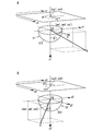
- two cameras 21 and 22 have a line segment (hereinafter referred to as “baseline”) in which the optical axes are parallel and the optical centers O1 and O2 of both cameras 21 and 22 are connected.
- the parallel stereo method is used, which is arranged perpendicular to both optical axes. Therefore, the entire fields of view of the two cameras 21 and 22 overlap.
- the direction of the baseline is made to coincide with the horizontal direction of an image (hereinafter referred to as “captured image”) obtained by capturing each of the cameras 21 and 22.
- the length of the baseline (hereinafter referred to as “baseline length”) and two Information on the distance of the image position deviation corresponding to the point of interest Q in the target space is necessary.
- the distance of the image position deviation is the parallax when the region of interest in the target space is viewed from the two cameras 21 and 22, from the reference position defined in each of the two captured images to the image position.
- the distance difference is the distance from the reference position to the image position in the captured image captured by the camera 21 and the position of the image from the reference position in the captured image captured by the camera 22. It is the difference with the distance to.
- the distance of the image position corresponding to the point of interest Q is the parallax when the point of interest Q is viewed from the two cameras 21 and 22.
- the parallax from the two captured images it is necessary to find the position of the image corresponding to the region of interest in the target space among the two captured images. That is, it is necessary to specify corresponding points corresponding to the same part in the two captured images.
- the process of searching for corresponding points from two captured images is called stereo matching.
- the range for searching for corresponding points on two captured images in stereo matching is as follows. It can be limited to a line obtained by projecting an epipolar surface on the image.
- the direction along the horizontal direction of the light receiving surface is the x direction
- the direction along the vertical direction with respect to the x direction on the light receiving surface is the y direction
- a device coordinate system in which the direction orthogonal to the light receiving surface is the z direction is defined.
- the x direction (first direction of the apparatus coordinate system) matches the direction of the baseline
- the right direction in the horizontal direction of the captured image is the positive direction of the x direction.
- the camera coordinate system for each of the cameras 21 and 22 is defined.
- the camera coordinate system has coordinate axes parallel to the coordinate axes of the apparatus coordinate system, but the origin uses optical centers O1 and O2 for the cameras 21 and 22, respectively.
- the coordinate axes of the camera coordinate system defined for the camera 21 are represented by x1, y1, z1, and the coordinate axes of the camera coordinate system defined for the camera 22 are x2, y2. , Z2.
- the z1 axis coincides with the optical axis of the camera 21, and the z2 axis coincides with the optical axis of the camera 22.
- the apparatus coordinate system matches the camera coordinate system set for the camera 21.
- the direction of looking at the target point Q of the target space from the optical center O1 that is the origin is, as shown in FIG. 4A, the angle ⁇ 1 with respect to the z1 axis and the target point Q from the optical center O1. This is expressed using an angle ⁇ 1 around the z1 axis from the x1 axis when the direction to be seen is projected onto the x1y1 plane.
- the distance r1 from the optical center O1 to the point where the point of interest Q is projected on the x1y1 plane is used. As shown in FIG.
- the camera coordinate system related to the other camera 22 has the same relationship. That is, in the camera coordinate system relating to the camera 22, in order to describe the position of the point of interest Q, the angle ⁇ 2 with respect to the z2 axis and the direction in which the point of interest Q is viewed from the optical center O2 are projected on the x2y2 plane from the x2 axis to z2. The angle ⁇ 2 around the axis and the distance r2 from the optical center O2 to the point where the point of interest Q is projected onto the x2y2 plane are used.
- the parallelogram shown at the top represents a captured image.
- an image coordinate system that is a two-dimensional orthogonal coordinate system with the upper left corner of the captured image as the origin is used to represent the position of the pixel in the captured image obtained for each of the cameras 21 and 22.
- the horizontal direction (first direction of the image coordinate system) of the captured image is in the x1 direction (first direction of the apparatus coordinate system).
- the vertical direction (second direction of the image coordinate system) in the captured image is set to be along the y1 direction (second direction of the apparatus coordinate system) in the captured image, and an arbitrary coordinate position in the captured image Is represented by (u1, v1).
- the image coordinate system of the captured image obtained by the camera 22 is set so that the horizontal direction of the captured image is along the x2 direction and the vertical direction with respect to the horizontal direction of the captured image is along the y2 direction.
- An arbitrary coordinate position in the captured image is represented by (u2, v2).
- the coordinate position (u1, v1) of the image coordinate system of the captured image obtained by the camera 21 and the coordinate position (u2, v2) of the image coordinate system of the captured image obtained by the camera 22 will be described without distinction. In this case, the coordinate position (u, v) is used.
- the measuring device 20 includes an arithmetic processing unit 23 that calculates the three-dimensional data of the target space using the captured images captured by the cameras 21 and 22.
- the arithmetic processing unit 23 includes a processor and a memory as hardware resources, and an interface unit for inputting and outputting data, and executes a program for causing the device to function as a device that performs processing described below.
- the device constituting the arithmetic processing unit 23 may be a digital signal processor (DSP), a field-programmable gate array (FPGA), or the like in addition to a microcomputer.
- DSP digital signal processor
- FPGA field-programmable gate array
- a device having a function of executing a program that is, a device corresponding to a computer
- the arithmetic processing unit 23 may be configured by dedicated hardware.
- Equation 1 is established between the coordinates (u, v).
- f is a proportionality constant in the equidistant projection method.
- the coordinates of the optical center O1 projected on the captured image captured by the camera 21 are (uc1, vc1), and the optical center projected on the captured image captured by the camera 22 is used.
- the coordinates of O2 be (uc2, vc2).
- the point of interest Q in the target space is projected onto a spherical surface having a radius of 1 centered on the optical centers O1 and O2 of the cameras 21 and 22.
- the orthogonal coordinates (xa, ya, za) of the camera coordinate system of the point where the point of interest Q is projected on the spherical surface the polar coordinates (r, ⁇ , ⁇ ) of the camera coordinate system described above are used, Equation 2 is obtained. It is expressed in A similar relationship is obtained for both cameras 21 and 22.
- the orthogonal coordinates (xa1, ya1, za1) of the camera coordinate system of the point where the point of interest Q is projected onto the spherical surface are the polar coordinates (r1, ⁇ 1, ⁇ 1) of the camera coordinate system.
- the orthogonal coordinates (xa2, ya2, za2) of the camera coordinate system at the point where the point of interest Q is projected onto the spherical surface are expressed using the polar coordinates (r2, ⁇ 2, ⁇ 2) of the camera coordinate system.
- the arithmetic processing unit 23 of the present embodiment has a function of converting an image represented by coordinates (u, v) into an image represented using angles ( ⁇ , ⁇ ).
- the angle ⁇ 1 is such that a straight line La1 that looks at the point of interest Q from the optical center O1 is in a plane including the x1 axis and the point of interest Q (corresponding to the epipolar plane EP1) with respect to the y1z1 plane. It is the angle to be made.
- the angle ⁇ 1 is an angle formed by the straight line La2 obtained by projecting the straight line La1 that looks at the point of interest Q from the optical center O1 on the y1z1 plane with respect to the z1 axis.
- the angle ⁇ 1 is an angle formed by the epipolar plane EP1 with respect to the z1 axis.
- the angle ⁇ 1 is 0 degree on the y1z1 plane, and the angle ⁇ 1 is 0 degree on the z-axis. Therefore, when the angle ( ⁇ , ⁇ ) is expressed using the coordinates (xa, ya, za), the relationship of Equation 3 is obtained.
- Equation 1 to Equation 3 When the relationship of Equation 1 to Equation 3 is applied to all pixels of the captured image, the relationship of the coordinates (xa, ya, za) expressed using the coordinates (u, v) of the image coordinate system is the angle ( ⁇ , ⁇ ). It will be represented by When an image having the angle ⁇ as the horizontal direction and the angle ⁇ as the vertical direction is generated, the pixel position is represented by the angle ( ⁇ , ⁇ ) from the captured image in which the pixel position is represented by the coordinates (u, v). Converted to an image.
- an image in which pixel positions are represented by angles ( ⁇ , ⁇ ) is referred to as a “transformed image”.
- the arithmetic processing unit 23 performs the same conversion on the captured image captured by the other camera 22 to generate a converted image.
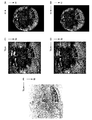
- 6A illustrates an example of a captured image captured by the camera 21
- FIG. 6B illustrates an example of a captured image captured by the camera 22.
- 6C illustrates an example of a converted image corresponding to the captured image illustrated in FIG. 6A
- FIG. 6D illustrates an example of a converted image corresponding to the captured image illustrated in FIG. 6B.
- the angles ⁇ 1 and ⁇ 2 (see FIG. 3A) for viewing the same point of interest Q coincide. That is, in stereo matching described later, attention should be paid to the angles ⁇ 1 and ⁇ 2 (see FIG. 3A) of the converted image, and the stereo matching process is simplified.
- the arithmetic processing unit 23 estimates the parallax of the cameras 21 and 22 using the obtained two converted images, and uses the estimated parallax for calculating the three-dimensional data of the target space. In order to estimate the parallax of the cameras 21 and 22, the arithmetic processing unit 23 extracts corresponding points corresponding to the same position in the target space from the two converted images.
- the technique for extracting the corresponding points is not particularly limited, but in this embodiment, a block matching technique is adopted.
- the arithmetic processing unit 23 performs the coordinate ( ⁇ 2) of the corresponding point from the converted image with respect to the captured image of the camera 22 with respect to the coordinates ( ⁇ 1, ⁇ 1) of the point extracted from the converted image with respect to the captured image of the camera 21 by block matching. , ⁇ 2).
- I1 ( ⁇ 1 + i, ⁇ 1 + j) and I2 ( ⁇ 2 + i, ⁇ 2 + j) are luminance values for each converted image, and the block size is (2N + 1) pixels in the horizontal direction and (2M + 1) pixels in the vertical direction. N and M are natural numbers determined as appropriate.
- Equation 4 evaluates the sum of the differences (absolute values) of pixel values (luminance values) I1 ( ⁇ 1 + i, ⁇ 1 + j) and I2 ( ⁇ 2 + i, ⁇ 2 + j) for the pixel position (i, j) set in the converted image.
- R used for R. That is, as the evaluation value R, SAD (Sum of Absolute Difference) is used. However, as the evaluation value R, an SSD (Sum of Squared Difference) or a normalized cross-correlation function can be used.
- block matching is performed in order to obtain corresponding points, but other techniques of stereo matching may be employed, and stereo matching may be performed without using a converted image.
- the converted image is an image in which the horizontal axis of the image is ⁇ and the vertical axis is ⁇ , but an image converted by another conversion method may be used.
- the arithmetic processing unit 23 calculates the three-dimensional coordinates of the corresponding points (that is, the point of interest Q) in the target space by using the principle of the triangulation method. As shown in FIGS. 3A and 3B, when the angles ( ⁇ 1, ⁇ 1) and ( ⁇ 2, ⁇ 2) for viewing the point of interest Q from the origin of the camera coordinate system set for each of the two cameras 21 and 22 are used, the apparatus coordinate system is used.
- the arithmetic processing unit 23 calculates the distance Lq by performing the calculation of Equation 6 for all the target points Q in the target space, and generates a distance image with the pixel values at the coordinates ( ⁇ 1, ⁇ 1) of the converted image as the distance Lq.
- the measurement device 20 obtains three-dimensional data of the target space, and further generates a parallax image whose pixel value is the parallax Dq and a distance image whose pixel value is the distance Lq.
- the target space is an indoor space of a building and the reference surface is a floor surface will be described as an example.
- the target space may be an outdoor space of a building or a space formed outside the building.
- the reference surface is a wall surface, a ceiling surface, a desk surface, or the like, a technique similar to the technique described below can be employed.
- the target space is the indoor space of the building and the reference plane is the floor.
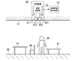
- the measuring device 20 has the optical axes of the cameras 21 and 22 facing downward near the center of the ceiling 51, as shown in FIG. A description will be given based on the case where they are arranged.
- the xy plane in the device coordinate system defined in the measuring device 20 is not always parallel to the floor surface 50, and in some cases, the measuring device 20 cannot be disposed on the ceiling 51. In some cases, it may be placed on the wall.
- the spatial information detection device 10 includes an acquisition unit 11 that acquires three-dimensional data from the measurement device 20 and a storage unit 12 that stores the three-dimensional data acquired by the acquisition unit 11.
- the acquisition unit 11 is an interface unit for connecting the measurement device 20, and is configured according to a communication specification in which the measurement device 20 outputs three-dimensional data.
- the storage unit 12 includes a first storage unit 121 that stores three-dimensional data (first three-dimensional data) for each measurement by the measurement device 20. Further, the storage unit 12 compares the reference three-dimensional data (second three-dimensional data) measured by the measurement device 20 at a predetermined timing with the measurement measured by the measurement device 20 to detect a change in the target space. 2nd memory
- storage part 122 which memorize
- the three-dimensional data stored in the first storage unit 121 is acquired for each frame of the captured image captured by the cameras 21 and 22.
- the frame rate of the captured image may be 30 frames per second as in a general moving image, but is appropriately set within a range of about 0.1 to 30 frames per second depending on the level of allowable processing load. Is done.
- the reference three-dimensional data (second three-dimensional data) stored in the second storage unit 122 is measured by the measurement device 20 at a timing when there is no moving object in the visual field of the measurement device 20, and is acquired by the acquisition unit 11. Is preferably obtained from the measuring device 20. If there is a moving object, an image having the pixel value as the median luminance of images taken at consecutive different times may be created, and the reference three-dimensional data may be obtained from the image.
- the reference three-dimensional data is so-called background three-dimensional data. When the difference between the comparison three-dimensional data (third three-dimensional data) and the background three-dimensional data is obtained, whether there is a change in the target space. And where the change occurred.
- storage part 122 is used as a one part component of the human position detection apparatus 30 mentioned later.
- the spatial information detection apparatus 10 uses the three-dimensional data stored in the first storage unit 121 to identify the floor surface 50 included in the captured image, and uses the entire floor surface 50 of the target space as a reference plane.
- a reference setting unit 13 is provided. Data regarding the floor surface 50 included in the captured image is included in the three-dimensional data stored in the first storage unit 121.
- the reference surface defined by the reference setting unit 13 includes not only the floor surface 50 included in the captured image but also the floor surface 50 hidden by a fixture or the like arranged in the target space. That is, the reference setting unit 13 estimates the floor surface 50 in an area that is not visible in the captured image, based on information on the floor surface 50 that is visible in the captured image captured by the cameras 21 and 22 provided in the measurement device 20. In addition, the estimated floor surface 50 is used as a reference surface.
- the device coordinate system In the state where the measuring device 20 is installed, the device coordinate system is known, but the spatial coordinate system defined in the target space is unknown. Therefore, in order for the reference setting unit 13 to determine the reference plane, information on the orientation of the reference plane and the distance to the reference plane in the apparatus coordinate system set in the measurement apparatus 20 is required.
- the spatial information detection device 10 sets a plurality of small planes in a region of interest including the floor 50 in the target space, and obtains the orientation of each of the plurality of small planes in the coordinate system defined by the measurement device 20.
- An element calculation unit 14 is provided.
- the plurality of small planes are set by dividing the entire region of interest, or are set at appropriate intervals in the region of interest.
- the surface element calculation unit 14 obtains a normal vector for each small plane using the three-dimensional data in the region of interest, and sets the direction represented by the normal vector as the direction of the small plane.
- the region of interest is a partial region in the target space in order to determine a reference plane for measuring the target space, and is extracted in advance before the surface element calculation unit 14 determines the orientations of a plurality of small planes.
- the size of the normal vector of the surface element represents the area of the surface element, but in this embodiment, the area of the small plane is not used.
- the measuring device 20 is arranged with the position accurately aligned with respect to the ceiling 51. That is, the measuring device 20 is arranged so that the optical axes of the cameras 21 and 22 (that is, the z axis of the device coordinate system) are parallel to one axis (Z axis) of the spatial coordinate system defined in the target space.
- the Z-axis of the spatial coordinate system is orthogonal to the floor surface 50
- the X-axis and Y-axis of the spatial coordinate system are set in appropriate directions orthogonal to each other and orthogonal to the Z-axis.
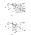
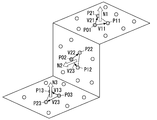
- the surface element calculation unit 14 extracts a combination of adjacent three points P0i, P1i, P2i from the three-dimensional data acquired by the acquisition unit 11 from the measuring device 20 (i is a natural number).
- the normal vector [Ni] of the small plane defined by the extracted three points is calculated.
- the circles in FIG. 7 represent points where three-dimensional data is obtained.
- the distances between the three points P0i, P1i, and P2i that define the small plane are preferably as small as possible. However, it is not essential that the distance between the three points is the minimum, and any distance that allows evaluation of the reference plane is acceptable. Is done.
- the two points P1i and P2i that are the distance range defined from one point P0i may be selected.
- the three points P0i, P1i, and P2i that define the small plane are obtained in the region of interest that is a part of the region for which three-dimensional data is obtained in the target space, but the three-dimensional in the target space. You may obtain
- vectors [V1i] and [V2i] from one point P0i out of the extracted three points P0i, P1i and P2i to the other two points P1i and P2i, the vectors are defined by three points P0i, P1i and P2i.
- the normal vector [Ni] of the small plane is expressed by the outer product [V1i] ⁇ [V2i] of the vectors [V1i] and [V2i].
- the z-axis of the device coordinate system is parallel to the Z-axis of the spatial coordinate system. Therefore, if the small plane is a part of the floor surface 50, the outer product [V1i] ⁇ [V2i] of the vectors [V1i] and [V2i] is parallel to the z-axis of the apparatus coordinate system.
- the direction of the outer product [V1i] ⁇ [V2i] changes depending on the direction of the vectors [V1i] and [V2i]
- the direction of the small plane is opposite depending on how [V1i] and [V2i] are set.
- the normal vector [Ni] of the floor surface 50 must be in the same direction.
- the normal vector [Ni] of the small plane used to define the reference plane is positive in the direction from the small plane toward the measuring device 20. For this reason, when the direction of the normal vector [Ni] of the small plane is downward, the sign is inverted so as to be upward.
- the small plane may be formed in a part other than the floor surface 50, and the small plane other than the floor surface 50 needs to consider the direction if it is a real space. Since the focus is on the small plane for defining the reference plane, the same rule is applied to small planes other than the floor 50. That is, the sign is ignored for all facets.
- the region of interest can be only the floor surface 50. Therefore, normal vectors of a plurality of small planes obtained from the region of interest [ Ni] is considered to be in substantially the same direction. In such a case, the orientation of the reference plane can be determined by obtaining the average of the orientations of the normal vectors [Ni] of the obtained plurality of small planes.
- the spatial information detection apparatus 10 of the present embodiment extracts the floor surface 50 from the region of interest by using the frequency distribution for the directions of the normal vectors [Ni] of the plurality of small planes calculated by the surface element calculation unit 14. .
- the surface element calculation unit 14 may determine a region of interest using a plurality of sets of three-dimensional data obtained from captured images of a plurality of frames captured by the cameras 21 and 22 of the measurement device 20.
- the surface element calculation unit 14 extracts a region of interest from a region in the target space that is within an error range defined by a change in the three-dimensional data stored in the first storage unit 121.
- the surface element calculation unit 14 obtains a difference in z coordinates for each same position on the xy plane as a change in a plurality of three-dimensional data, and extracts a part where the difference is within an error range as a region of interest.
- each of the plurality of three-dimensional data includes an x-coordinate (first coordinate) and a y-coordinate (second coordinate) representing a position in a direction parallel to the light receiving surface of the measuring device 20 as a device coordinate system, and a device And a z coordinate (third coordinate) representing a position in a direction orthogonal to the light receiving surface in the coordinate system.
- the surface element calculation part 14 calculates
- the reliability of the normal vector [Ni] obtained from the three-dimensional data may be reduced due to irregular measurement errors in the measurement apparatus 20 and the presence of moving objects in the target space. Therefore, normal vectors [Ni] are obtained from a plurality of sets of three-dimensional data, and normal processing is performed on the direction of the normal vectors [Ni] (for example, averaging and removal of outliers) to obtain normal vectors. It is desirable to increase the reliability of the direction of the vector [Ni]. That is, the surface element calculation unit 14 obtains orientation candidates for each of the plurality of small planes a plurality of times from a plurality of sets of three-dimensional data measured by the measuring device 20 at different times, and each direction of the plurality of small planes. It is desirable to determine the orientation of each of the plurality of facets by statistical processing on the candidates.
- the orientation of the normal vector [Ni] of the small plane is represented by a coherence angle ( ⁇ ) and an azimuth angle ( ⁇ ) of the dip angle using a device coordinate system based on spherical coordinates.
- the angle ⁇ is an angle formed by a straight line that looks at the starting point of the normal vector [Ni] from the origin of the apparatus coordinate system with respect to the z axis of the apparatus coordinate system, and the angle ⁇ is a normal to the xy plane of the apparatus coordinate system. This is the angle formed by the projection of the vector [Ni] with respect to the x axis.
- the angle ( ⁇ , ⁇ ) representing the direction of the normal vector [Ni] for each small plane is defined by the following equation.
- the spatial information detection apparatus 10 includes a distribution extraction unit 15 that obtains a frequency distribution with respect to the direction of the normal vector [Ni] for each small plane.
- the distribution extraction unit 15 divides the angle ( ⁇ , ⁇ ) indicating the direction of the normal vector [Ni] into sections of a predetermined width to obtain a frequency distribution. In other words, this corresponds to quantizing the angle ( ⁇ , ⁇ ) and obtaining the frequency distribution for the angle ( ⁇ , ⁇ ) after quantization.
- Quantization can be performed simply by quantizing to an integer value with the unit of angle ( ⁇ , ⁇ ) being [degrees]. In this case, the frequency is obtained by dividing into sections of 1 degree.
- the quantization step size can be set as appropriate, and the step size may be narrowed to increase the accuracy.
- the reference setting unit 13 determines the distribution. In the frequency distribution obtained by the extraction unit 15, a direction that is a frequency equal to or higher than a specified direction threshold value can be determined as the direction of the floor surface 50.
- the distribution extraction unit 15 sets a constraint condition so as to obtain a frequency distribution for a direction within a specified direction range among a plurality of facet directions. It is desirable to keep it.
- the purpose is to extract the floor surface 50, and since the measuring device 20 is disposed on the ceiling 51 (see FIG. 2), it is considered that the angle ⁇ is concentrated in the vicinity of zero. Therefore, when the distribution extraction unit 15 obtains the frequency distribution for only the normal vector [Ni] within the predetermined angle range from 0 with respect to the angle ⁇ among the plurality of small-plane normal vectors [Ni], the processing is performed. In addition to greatly reducing the load, the possibility of extracting other than the floor surface 50 is reduced.
- the spatial information detection device 10 includes a communication unit that receives an instruction of an angle range from the input unit, and a storage unit that stores a constraint condition. Is desirable. If the angle range is limited for the angle ⁇ , the normal vector [Ni] in a direction clearly different from the reference plane is excluded. Therefore, it is possible to accurately determine the reference plane even in a complicated shape in which many normal vectors [Ni] in a direction different from the reference plane exist within the measurement range of the measuring device 20.
- the desk surface 41 and the seat surface 42 of a chair, and the floor surface 50 are substantially. Since it is considered to be parallel (see FIG. 2), there is a possibility that the desk surface 41 and the seating surface 42 may be mistaken for the floor surface 50 only by the information of the frequency distribution of the angles ( ⁇ , ⁇ ).
- the measuring device 20 is arranged in the upper part of the target space such as the ceiling 51, the distance from the floor surface 50 is larger than the distance from the desk top surface 41, the seating surface 42, the shelf top surface, and the like. it is conceivable that.
- the reference setting unit 13 extracts the small planes included in the frequency equal to or higher than the direction threshold in the frequency distribution of the angles ( ⁇ , ⁇ ), and the measuring device 20 in the normal direction for each extracted small plane.
- the distance that is, the height
- the facet having the maximum obtained distance is determined.
- the small plane with the maximum distance is determined by the following method, for example.
- the reference setting unit 13 obtains a frequency distribution with the abscissa indicating the distance (height) of the extracted small plane.
- the reference setting unit 13 applies a general mixed normal distribution to the obtained frequency distribution, and applies a plurality of normal distributions.
- the reference setting unit 13 sets the small plane closest to the average as the small plane having the maximum distance.
- This method is an example, and the facet with the maximum distance may be determined by other methods.
- the reference setting unit 13 extracts the small planes that are candidates for the reference plane by using the orientations of the plurality of small planes, and the distance from the measuring device 20 in the direction of the normal of the small plane that is the candidate for the reference plane. To extract a small plane included in the reference plane.
- the three-dimensional data (xp, yp, zp) of the starting point of the vector it is obtained as nx ⁇ xp + ny ⁇ yp + nz ⁇ zp. That is, the height of the measuring device 20 in the direction of the normal vector is obtained from the inner product of the normal vector of the small plane and the position vector representing the position of the start point of the normal vector.
- the distance between the measurement device 20 and the small plane in the normal direction of the small plane is compared with the distance threshold.
- the frequency is equal to or greater than a predetermined threshold using the frequency distribution of the distance, and the frequency A small plane belonging to a section having the maximum distance in the distribution may be extracted.
- the obtained distance may be quantized to obtain the frequency, and a facet having a relatively high frequency and a maximum quantized distance may be extracted.
- the reference setting unit 13 extracts a small plane estimated to be included in the reference plane from a plurality of small planes, and then sets the reference plane using the extracted small plane. That is, the reference setting unit 13 fits the extracted small plane on one plane and uses this plane as the reference plane (floor surface 50).
- a known technique such as the least square method or RANSAC (RANdomRANSAmple Consensus) is used.
- the direction in which the frequency is maximized is defined as the Z direction (the third direction of the spatial coordinate system), and a spatial coordinate system is defined in which the plane orthogonal to the Z direction is the XY plane. It becomes possible.
- the X direction (the first direction in the spatial coordinate system) and the Y direction (the second direction in the spatial coordinate system) can be appropriately set in the XY plane. It is desirable to set the X direction and the Y direction based on the above.
- the x-axis and the y-axis in the device coordinate system of the measuring device 20 may be projected onto the XY plane, the x-axis projection may be the X-axis, and the y-axis projection may be the Y-axis.
- the set coordinate values of the spatial coordinate system are stored in the storage unit 12 in association with the coordinate values of the apparatus coordinate system. Accordingly, the storage unit 12 stores data for coordinate conversion from the device coordinate system to the spatial coordinate system.
- the spatial coordinate system By determining the spatial coordinate system, coordinate conversion from the three-dimensional data of the device coordinate system to the spatial coordinate system becomes possible. That is, it is possible to obtain the height of the object relative to the reference plane (floor surface 50) using the three-dimensional data of the object existing in the target space.
- the calculation for calculating the height of the object with respect to the reference plane is performed by the height calculation unit 16 provided in the spatial information detection device 10. Since the height calculation unit 16 determines the height of the object with respect to the floor surface 50, the three-dimensional shape of the object is determined by combining with the outer peripheral shape of the object along the floor surface 50.
- the light receiving optical systems 212 and 222 of the measuring device 20 are fisheye lenses or lenses having a function corresponding to the fisheye lens, in the captured image, the periphery is closer to the central region near the optical axes of the cameras 21 and 22.
- the amount of information per unit area is larger in the side area. Therefore, the measurement accuracy is higher in the central area of the captured image than in the peripheral area of the captured image. That is, since the variable range of the angle ⁇ is 0 ⁇ ⁇ ⁇ ⁇ / 2, the measurement accuracy increases when the angle ⁇ is near 0, and the measurement accuracy decreases when the angle ⁇ is near ⁇ / 2.
- the distribution extraction unit 15 multiplies the frequency by a weighting factor according to the position of the three-dimensional data for which the angle ( ⁇ , ⁇ ) has been obtained. It is desirable.
- the weighting factor is preferably obtained by multiplying the three-dimensional data corresponding to the central region of the captured image by a larger weighting factor than the three-dimensional data corresponding to the peripheral region of the captured image.
- the weighting coefficient w is determined as follows.
- the weight distribution is set according to the information amount and the frequency distribution is obtained, thereby obtaining the information obtained from the frequency distribution. It becomes possible to increase reliability. That is, the reliability of reference plane extraction based on the frequency distribution is increased.
- the frequency distribution of the angle ( ⁇ , ⁇ ) is generated using the three-dimensional data obtained by one imaging, but the position of the measuring device 20 is fixed, and thus the plurality of times.
- the frequency distribution may be generated using the three-dimensional data obtained by imaging.
- the frequency difference is widened, so that discrimination based on the orientation threshold becomes easier.
- the reference plane is detected using the frequency distribution of the normal direction of the small plane (that is, the angle ( ⁇ , ⁇ )), the reference plane can be detected easily and accurately. Moreover, since the reference plane is estimated in consideration of the distance from the measuring device 20 to the reference plane, when detecting the floor 50, the floor 50 such as the desk top 41, the chair seat 42, or the shelf top. It is possible to prevent erroneous detection of a plane parallel to the. That is, when detecting the position of a person, which will be described later, it is possible to detect the position of the person 40 (see FIG. 2) excluding the area where the desks and shelves are arranged.
- the spatial information detection device 10 Since the spatial information detection device 10 automatically obtains the inclination and distance of the reference surface with respect to the measurement device 20 and automatically extracts the relationship between the reference surface and the measurement device 20 in the target space, only the measurement device 20 is installed. Thus, conversion from the device coordinate system to the spatial coordinate system becomes possible. Further, by converting the three-dimensional data of the apparatus coordinate system into the three-dimensional data of the spatial coordinate system, it is possible to detect the height of the object with respect to the reference plane.
- the spatial information detection device 10 By using such a function of the spatial information detection device 10, it is possible to detect the presence / absence of the person 40 (see FIG. 2) and the position of the person 40 in the target space.
- a human position detection device 30 that detects the presence and position of the person 40 using the spatial information detection device 10 will be described with reference to FIG. 1.
- the human position detection device 30 uses both the reference three-dimensional data (second three-dimensional data) and the comparison three-dimensional data (third three-dimensional data) stored in the second storage unit 122.
- the presence / absence and position of 40 are detected.
- the second storage unit 122 stores a plurality of three-dimensional data acquired by the acquisition unit 11 at different times. Specifically, in the second storage unit 122, the reference three-dimensional data obtained during a period during which it is guaranteed that no person 40 exists in the target space and the comparison obtained during the period during which the target space is monitored. 3D data for use are stored.
- the reference three-dimensional data obtained during a period in which the person 40 does not exist in the target space is three-dimensional data corresponding to the background of the target space, it is hereinafter referred to as “background data”. Further, the comparison three-dimensional data obtained during the period of monitoring the target space is called “monitoring data” because it is the three-dimensional data to be monitored.
- the human position detection device 30 includes a difference calculation unit 31 that calculates a difference between the distance obtained using the monitoring data and the distance obtained using the background data, and the person 40 using the difference calculated by the difference calculation unit 31. And a human position estimating unit 32 for estimating the position where the
- the difference calculation unit 31 obtains a difference between the values of the distance Lq for each of the same coordinates ( ⁇ , ⁇ ) in the distance image between the monitoring data and the background data. That is, the difference calculation unit 31 extracts a part where a change has occurred with respect to the background data by obtaining the difference of the distance Lq from the measurement device 20.
- the region where the distance Lq has changed with respect to the background data is considered to correspond to the moved object, and since the moved object has the possibility of being a person 40, the difference between the monitoring data and the background data. If there is a region where the change occurs, this region is regarded as a candidate region of the person 40, that is, a candidate region where the person 40 exists. However, when the difference is small, there is a possibility of an error, and when the small animal moves in the target space, the difference may change.
- the human position estimation unit 32 defines the difference (difference between the monitoring data and the background data) obtained by the difference calculation unit 31 in order to detect the person 40 by removing the change in the difference due to an error or a small animal. If the determination threshold is exceeded, the region where the difference has changed is determined as a region that is a candidate for the person 40. That is, the human position estimation unit 32 binarizes the difference between the monitoring data and the background data by the determination threshold value.
- the binarized data is a binary image in which 1 is associated with pixels exceeding the threshold and 0 is associated with pixels below the threshold. That is, an area having a pixel value of 1 in this binary image is an area that is a candidate for the person 40.
- the person position estimation unit 32 applies the data stored in the storage unit 12 to the region that is a candidate for the person 40, and performs coordinate conversion from the device coordinate system to the spatial coordinate system. By this coordinate transformation, the height from the reference plane is obtained for the region that is a candidate for the person 40. Accordingly, the human position estimation unit 32 compares the height from the reference plane obtained from the candidate area of the person 40 with the height range specified based on the height of the person 40, thereby comparing the person 40 and the others. It is distinguished from the object. With this process, even objects that move, such as chairs, trash cans, and notebook computers, are excluded from the candidates for the person 40 if the height from the reference plane is not within the specified height range.
- the human position estimation unit 32 measures the height of the object existing in the target space from the reference plane using the estimated direction and distance of the reference plane, the person 40 and other objects are measured in height. Differentiating by difference, the possibility of misdetecting other objects is reduced. In addition, since the height range from the floor 50 that is the reference surface is defined, it is possible to prevent erroneous detection of an object having a height that is clearly different from the height of the person 40.
- the human position estimation unit 32 obtains the center of gravity of the regions that form the cluster among the detected candidates of the person 40 and sets the position of the person 40 projected on the reference plane as the position of the person 40.
- the area forming the cluster means a set of points that are distances within a predetermined threshold by evaluating the distance between the points (points corresponding to the pixels) included in the area.
- a known clustering method such as Mean-Shift clustering may be employed.
- the technique using the difference between the monitoring data that is three-dimensional data and the background data has been described.
- the candidate area of the person 40 is obtained using the difference between the parallax images generated by the measurement device 20. Is possible.
- the storage unit 12 stores the parallax Dq as a pixel value for each coordinate represented by angles ( ⁇ 1, ⁇ 1). Further, the difference calculation unit 31 obtains a difference between pixel values (parallax Dq) of the same coordinates ( ⁇ 1, ⁇ 1).
- the process performed by the human position estimation unit 32 is the same as the case of using three-dimensional data, and binarizes and extracts a region where the difference has changed, converts this region into height information from the reference plane,
- the center of gravity of the cluster may be the position of the person 40.
- the candidate area of the person 40 may be obtained by using the three-dimensional data and the parallax image together. That is, as described above, an area that is a candidate of the person 40 extracted by binarizing the difference of the three-dimensional data and an area of the candidate of the person 40 extracted by binarizing the difference of the parallax images Alternatively, the coordinates may be combined after the coordinate conversion, and the combined area may be used as a candidate area for the person 40. For the synthesis of the regions, if logical sum is used, the candidate regions of the person 40 can be easily detected, and if logical product is used, the candidate regions of the person 40 are narrowed down.
- the operation of the human position detecting device 30 in cooperation with the spatial information detecting device 10 is collectively shown in FIG.
- the illustrated example shows a case where three-dimensional data (distance image) is used.
- the acquisition unit 11 of the spatial information detection device 10 acquires background data (second three-dimensional data) (S11), and stores the background data in the second storage unit 122 (S12).
- the reference setting unit 13 of the spatial information detection device 10 calculates the orientation and distance of the floor surface 50 (S13, S14), and stores data for coordinate conversion from the device coordinate system to the spatial coordinate system in the storage unit 12. Store (S15).
- the acquisition unit 11 of the spatial information detection device 10 acquires monitoring data (third three-dimensional data) (S16), and the difference calculation unit 31 of the human position detection device 30 uses the difference between the monitoring data and the background data.
- a candidate area for the person 40 is extracted (S17).
- the human position estimating unit 32 of the human position detecting device 30 evaluates whether or not the person 40 exists in the area based on the height from the floor 50 (S18), and evaluates that the person 40 exists in the area.
- the person position detecting device 30 calculates the center of gravity of the area forming the cluster as the position of the person 40 (S19).
- the operations in steps S16 to S19 including acquisition of monitoring data are repeated at appropriate time intervals until the monitoring is completed (S20: Yes).
- the measurement device 20 and the spatial information detection device 10 are described as separate bodies. However, these devices are integrated into a single housing and configured. Also good.
Landscapes
- Physics & Mathematics (AREA)
- General Physics & Mathematics (AREA)
- Engineering & Computer Science (AREA)
- Theoretical Computer Science (AREA)
- Computer Vision & Pattern Recognition (AREA)
- Length Measuring Devices By Optical Means (AREA)
- Image Processing (AREA)
Abstract
空間情報検出装置は、取得部と基準設定部と面素算出部とを備える。取得部は、対象空間に関して計測装置が計測した3次元データを取得する。面素算出部は、対象空間における着目領域に複数個の小平面を設定し、着目領域における3次元データを用いることにより、小平面ごとに、計測装置に規定した装置座標系での向き、および計測装置からの距離を求める。基準設定部は、面素算出部が求めた小平面ごとの向きおよび距離に基づいて対象空間を計測するための基準面を定める。
Description
本発明は、3次元計測の対象である対象空間における基準面を自動的に定める空間情報検出装置、および空間情報検出装置が定めた基準面に基づいて対象空間に存在する人の位置を検出する人位置検出装置に関するものである。
従来から、対象空間の形状や対象空間に存在する物体の位置や形状を計測するために、対象空間の3次元計測を行う技術が提案されている。たとえば、日本国公開特許第2009-174830号公報(以下「文献1」という)では、冷暖房を行う対象空間の3次元計測を行うことにより、対象空間に存在する人の位置を検出し、人の位置に合わせて送風方向や送風速度を調節する技術が提案されている。
文献1に記載された技術では、投射光を出射してから、物体で反射された反射光を受光するまでの時間を用いて物体までの距離を計測する飛行時間法(Time of Flight)を用いた距離計測を行っている。また、文献1に記載された技術では、対象空間における人の存否を、計測した距離の時間変化により求めている。また、人か否かを判別するために人の形状の特徴を用いている。すなわち、文献1に記載された技術では、人の形状を頭部、胴体、足部、手部の各部位に分割し、部位ごとの寸法ないし寸法比を用いることによって、距離変化が生じた部位について、形状の特徴から人か否かを判別している。
文献1に記載された技術は、3次元計測により得られた距離の時間変化を用いて人が存在する領域の候補を求め、候補の領域における形状の特徴により人を判断している。したがって、文献1に記載された技術を採用した場合、人体の一部が机や棚のような什器で遮蔽されている状態では、人を検出できない可能性がある。たとえば、オフィスのような対象空間において、広範囲な3次元計測を行うために、計測装置を天井のような高所に配置すると、計測装置からは机や棚のような什器に隠れて死角になる領域が生じやすくなる。
人の一部が死角になる領域に隠れていると、3次元計測により得られる距離の時間変化が生じる領域の範囲が小さくなり、また形状の特徴を判別できない可能性が生じる。そのため、距離の時間変化を精度よく把握できなくなり、人が存在するにもかかわらず人の検出に失敗する可能性が生じる。距離の時間変化を判断する基準を緩和すれば、人の検出に失敗する可能性が低減されるが、その一方で、人が移動させた椅子やゴミ箱などを人の候補と誤判断する可能性が高くなる。
ただし、人の検出に失敗するか、人以外の物体を誤検出するかは、トレードオフの関係であるから、判断の基準を調節するだけでは、判定の精度を高めることは困難である。すなわち、文献1に記載された技術のように、距離の時間変化と形状の特徴とを用いるだけでは、対象空間に机や棚などの什器が多く存在する場合に人を精度よく検出することは困難である。
ところで、対象空間には3次元計測を行う際の基準面になる床面や壁面が存在しているのが一般的である。このような基準面について、計測装置に対する向きや位置を求めておけば、計測装置に設定された座標系と対象空間における座標系との相対関係がわかる。計測装置が計測した3次元データを用いると、対象空間に存在する物体の相対位置が求められる。したがって、計測装置が計測した3次元データから基準面が求められていれば、物体の寸法および形状が求められ、結果的に物体の種類を特定することが可能になる。
たとえば、人の頭部は通常は床面から所定の高さ範囲に存在すると考えられるから、床面が求められていれば、床面に対する高さ範囲を規定することにより、人の存否を精度よく検出することが可能になる。
しかしながら、対象空間において、計測装置を取り付ける位置や向きは定まっていないから、計測装置の設置時には、計測装置の位置および向きに関するデータを校正用のデータとして人手によって与えなければならない。つまり、計測装置の設置毎に計測装置の位置および向きを入力する手間が必要になる。
本発明は、3次元計測の対象である対象空間における基準面を自動的に定めることにより、計測装置の設置毎に校正用のデータを入力する手間を省いて計測装置の設置時の作業効率を高め、また、基準面からの高さを用いることによって物体の計測を容易にした空間情報検出装置を提供することを目的とし、さらに、基準面を用いることにより、対象空間における人の存否および位置を精度よく検出する人位置検出装置を提供することを目的とする。
本発明に係る空間情報検出装置は、対象空間に関して計測装置が計測した第1の3次元データを取得する取得部と、前記対象空間における着目領域に複数個の小平面を設定し、前記着目領域における前記第1の3次元データを用いて前記複数個の小平面の各々について、前記計測装置に規定した装置座標系での向き、および前記計測装置からの距離を求める面素算出部と、前記面素算出部が求めた前記複数個の小平面の各々の向きおよび距離に基づいて前記対象空間を計測するための基準面を定める基準設定部とを備えることを特徴とする。
この空間情報検出装置において、前記面素算出部が算出した前記複数個の小平面の向きについて度数分布を求める分布抽出部をさらに備え、前記基準設定部は、前記分布抽出部が求めた度数分布において規定した向き閾値以上の度数である向きから前記基準面の向きを求めることが好ましい。
この空間情報検出装置において、前記分布抽出部は、前記複数個の小平面の向きのうち、指定された向き範囲内の向きについて前記度数分布を求めることが好ましい。
この空間情報検出装置において、前記計測装置は、広角レンズを備えるカメラで撮像した前記対象空間の画像を用いて前記第1の3次元データを出力する構成であって、前記分布抽出部は、前記複数個の小平面のうち前記画像の中心側の領域における小平面の向きの度数に、前記複数個の小平面のうち前記画像の周辺側の領域における小平面の向きの度数よりも大きい重みを付与して前記度数分布を求めることが好ましい。
この空間情報検出装置において、前記基準設定部は、前記複数個の小平面のうち、前記計測装置からの距離が最大である小平面から前記基準面を求めることが好ましい。
この空間情報検出装置において、前記対象空間は建物の空間であって、前記基準面は前記建物の床面であることが好ましい。
この空間情報検出装置において、前記第1の3次元データを用いることにより、前記対象空間に存在する物体に関して前記基準面からの高さを算出する高さ算出部をさらに備えることが好ましい。
この空間情報検出装置において、前記取得部が異なる時刻に取得した複数の前記第1の3次元データを記憶する記憶部をさらに備え、前記面素算出部は、前記記憶部に記憶された前記複数の前記第1の3次元データの変化が規定した誤差範囲内である領域から前記着目領域を抽出することが好ましい。
この空間情報検出装置において、前記面素算出部は、前記計測装置が異なる時刻に計測した複数組の前記第1の3次元データから前記複数個の小平面の各々の向きの候補を複数回ずつ求め、前記複数個の小平面の各々の向きの候補についての統計的処理により前記複数個の小平面の各々の向きを決定することが好ましい。
本発明の人位置検出装置は、床面からの高さを算出する空間情報検出装置と、前記取得部が前記対象空間に人が存在しないときに前記計測装置が計測した第2の3次元データを記憶する記憶部と、前記対象空間を監視する期間に前記計測装置が計測した第3の3次元データを用いて求めた距離と、前記記憶部が記憶している前記第2の3次元データを用いて求めた距離との差分を算出する差分演算部と、前記差分演算部により算出された前記差分が規定の判定閾値を超える領域について前記基準面に対する高さを評価することにより人が存在する位置を推定する人位置推定部とを備えることを特徴とする。
この人位置検出装置において、前記人位置推定部は、前記基準面に対する前記高さが指定された高さ範囲内である領域から前記人が存在する位置を求めることが好ましい。
本発明に係る空間情報検出装置の構成によれば、3次元計測の対象である対象空間における基準面が自動的に定められるから、計測装置の設置毎に校正用のデータを入力する手間を省いて計測装置の設置時の作業効率が高められ、また、基準面からの高さを用いることによって物体の計測が容易になるという利点がある。
本発明に係る人位置検出装置の構成によれば、空間情報検出装置が求めた基準面を用いることにより、対象空間における人の存否および位置が精度よく検出されるという利点がある。
本発明の好ましい実施形態をより詳細に記載する。本発明の他の特徴および利点は、以下の詳細な記載および添付図面に関連して一層よく理解される。
実施形態に係る空間情報検出装置および人位置検出装置を示すブロック図である。
実施形態に係る空間情報検出装置および人位置検出装置の使用例を示す概略構成図である。
図3A,3Bは実施形態に用いる計測装置の原理を説明する図である。
図4A,4Bは実施形態に用いる計測装置の原理を説明する図である。
図5A,5Bは実施形態に用いる計測装置の原理を説明する図である。
図6A~6Eは実施形態に用いる計測装置における画像例を示す図である。
実施形態に係る空間情報検出装置の動作説明図である。
実施形態に係る空間情報検出装置の動作説明図である。
実施形態に係る空間情報検出装置および人位置検出装置の処理手順をフローチャートで示す動作説明図である。
(計測装置)
以下に説明する実施形態では、ステレオビジョンの技術を用いて対象空間の3次元データを計測する計測装置を例示するが、3次元データを計測する技術は、ステレオビジョンに限らず、飛行時間や位相シフトなどの周知の種々の技術を採用可能である。
以下に説明する実施形態では、ステレオビジョンの技術を用いて対象空間の3次元データを計測する計測装置を例示するが、3次元データを計測する技術は、ステレオビジョンに限らず、飛行時間や位相シフトなどの周知の種々の技術を採用可能である。
本実施形態の計測装置20は、ステレオビジョンの技術を用いているから、図2のように、対象空間を撮像する複数台(図示例は2台)のカメラ21,22を備える。カメラ21,22は濃淡画像を出力することを想定しているが、カメラ21,22がカラー画像を出力する場合も以下に説明する技術思想は適用可能である。
カメラ21は、撮像素子211と受光光学系212とを備える。カメラ22は、撮像素子221と受光光学系222とを備える。撮像素子211,221は、CCDイメージセンサ、CMOSセンサのような周知の固体撮像素子が用いられる。また、受光光学系212,222は、対象空間から光を受ける光学系である。受光光学系212,222は、広角レンズであり、望ましくは魚眼レンズであるか魚眼レンズに相当する機能を有するレンズであり、カメラ21,22は、それぞれの画角が180度に近くなる。図示例では、受光光学系212,222がそれぞれ半球状の1個のレンズで模式的に表されている。受光光学系212,222の射影方式は、等距離射影方式、立体射影方式、等立体角射影方式、正射影方式のいずれでもよいが、以下では等距離射影方式を用いて説明する。
本実施形態は、図3A,3Bのように、2台のカメラ21,22が、光軸を平行にし、かつ両カメラ21,22の光学中心O1,O2を結ぶ線分(以下、「ベースライン」という)を両光軸に直交させて配置された平行ステレオ法を採用している。したがって、2台のカメラ21,22の視野はほぼ全体が重複する。また、本実施形態は、ベースラインの方向をカメラ21,22の各々の撮像によって得られた画像(以下、「撮像画像」という)の水平方向に一致させている。これらの制約条件を課すことにより、2台のカメラ21,22で撮像した撮像画像を用いて対象空間の3次元計測を行う際の処理負荷が低減される。ただし、これらの制約条件は必須というわけではない。
2枚の撮像画像を用いて光学中心O1,O2の各々から対象空間における着目点Qまでの距離を計測するには、ベースラインの長さ(以下、「ベースライン長」という)と、2枚の撮像画像の中で対象空間における着目点Qに対応する像の位置のずれの距離との情報が必要である。像の位置のずれの距離は、対象空間において着目する部位を2台のカメラ21,22から見込んだときの視差であって、2枚の撮像画像にそれぞれ規定した基準位置から像の位置までの距離差を用いる。すなわち、像の位置のずれの距離は、カメラ21で撮像された撮像画像の中における基準位置から像の位置までの距離と、カメラ22で撮像された撮像画像の中における基準位置から像の位置までの距離との差である。着目点Qに対応する像の位置のずれの距離は、着目点Qを2台のカメラ21,22から見込んだときの視差になる。
2枚の撮像画像から視差を求めるには、2枚の撮像画像の中で対象空間において着目する部位に対応する像の位置を探し出す必要がある。すなわち、2枚の撮像画像において同部位に対応する対応点を特定する必要がある。2枚の撮像画像から対応点を探索する処理をステレオマッチングと呼んでいる。2台のカメラ21,22のそれぞれの光学中心O1,O2と対象空間における着目点Qとを含むエピポーラ面を考えると、ステレオマッチングにおいて2枚の撮像画像上で対応点を探索する範囲は、撮像画像にエピポーラ面を投影した線上に限定することができる。
計測装置20には、受光面の水平方向(つまり、撮像画像の水平方向)に沿う方向をx方向、受光面におけるx方向に対する垂直方向(つまり、撮像画像の垂直方向)に沿う方向をy方向、受光面に直交する方向をz方向とする装置座標系を規定する。x方向(装置座標系の第1の方向)はベースラインの方向に一致し、撮像画像の水平方向における右向き(画像座標系の第1の方向の第1の側)がx方向の正の向き(装置座標系の第1の方向の第1の側)、撮像画像の水平方向における左向き(画像座標系の第1の方向の第2の側)がx方向の負の向き(装置座標系の第1の方向の第2の側)、撮像画像の垂直方向における下向き(画像座標系の第2の方向の第1の側)がy方向の正の向き(装置座標系の第2の方向の第1の側)、撮像画像の垂直方向における上向き(画像座標系の第2の方向の第2の側)がy方向の負の向き(装置座標系の第2の方向の第2の側)になるように規定され、受光面から遠ざかる向きをz方向の正の向き(装置座標系の第3の方向の第1の側)とする。装置座標系の原点は、ベースライン上であって一方のカメラ21の光学中心O1に設定される。
また、以下の説明において、カメラ21,22ごとのカメラ座標系を規定する。カメラ座標系は、装置座標系の座標軸と平行な座標軸を持つが、原点はカメラ21,22ごとの光学中心O1,O2を用いる。カメラ座標系の座標軸を装置座標系の座標軸と区別するために、カメラ21に規定するカメラ座標系の座標軸をx1,y1,z1で表し、カメラ22に規定するカメラ座標系の座標軸をx2,y2,z2で表す。z1軸は、カメラ21の光軸に一致し、z2軸は、カメラ22の光軸に一致する。本実施形態では、上述したように装置座標系の原点を設定しているから、装置座標系はカメラ21に設定したカメラ座標系と一致する。
一方のカメラ21に関するカメラ座標系において、原点である光学中心O1から対象空間の着目点Qを見込む方向は、図4Aに示すように、z1軸に対する角度θ1と、光学中心O1から着目点Qを見込む方向をx1y1平面に投影したときのx1軸からz1軸周りの角度φ1とを用いて表される。カメラ21に関するカメラ座標系では、着目点Qの位置を記述するために、角度(θ1,φ1)以外に、着目点Qをx1y1平面に投影した点までの光学中心O1からの距離r1を用いる。図4Bに示すように、他方のカメラ22に関するカメラ座標系についても同様の関係になる。すなわち、カメラ22に関するカメラ座標系では、着目点Qの位置を記述するために、z2軸に対する角度θ2と、光学中心O2から着目点Qを見込む方向をx2y2平面に投影したときのx2軸からz2軸周りの角度φ2と、着目点Qをx2y2平面に投影した点までの光学中心O2からの距離r2とを用いる。なお、カメラ21に関するカメラ座標系の極座標(r1,θ1,φ1)とカメラ22に関するカメラ座標系の極座標(r2,θ2,φ2)とを区別せずに説明する場合、極座標(r,θ,φ)と表す。
図4A,4Bにおいて、上部に示した平行四辺形は撮像画像を表している。撮像画像については、カメラ21,22ごとに得られた撮像画像における画素の位置を表すために、撮像画像の左上隅を原点とした2次元の直交座標系である画像座標系が用いられる。図4Aに示すように、カメラ21で得られた撮像画像の画像座標系は、撮像画像の水平方向(画像座標系の第1の方向)がx1方向(装置座標系の第1の方向)に沿っており、撮像画像における水平方向に対する垂直方向(画像座標系の第2の方向)がy1方向(装置座標系の第2の方向)に沿うように設定され、撮像画像中の任意の座標位置は(u1,v1)で表される。図4Bに示すように、カメラ22で得られた撮像画像の画像座標系は、撮像画像の水平方向がx2方向に沿っており、撮像画像における水平方向に対する垂直方向がy2方向に沿うように設定され、撮像画像中の任意の座標位置は(u2,v2)で表される。なお、カメラ21で得られた撮像画像の画像座標系の座標位置(u1,v1)とカメラ22で得られた撮像画像の画像座標系の座標位置(u2,v2)とを区別せずに説明する場合、座標位置(u,v)と表す。
計測装置20は、カメラ21,22ごとに撮像した撮像画像を用いて対象空間の3次元データを算出する演算処理部23を備える。演算処理部23は、ハードウェア資源としてのプロセッサおよびメモリと、データの入出力のためのインターフェイス部とを備え、以下に説明する処理を行う装置として機能させるためのプログラムを実行する。演算処理部23を構成するデバイスは、マイコンのほか、DSP(Digital Signal Processor)、FPGA(Field-Programmable Gate Array)などでもよい。要するに、演算処理部23には、プログラムを実行する機能を有したデバイス(つまり、コンピュータに相当するデバイス)が用いられる。ただし、演算処理部23は専用のハードウェアにより構成してもよい。
上述のように条件が設定されているから、撮像画像に投影した光学中心O1,O2の座標を(uc,vc)とすると、カメラ座標系の極座標(r,θ,φ)と画像座標系における座標(u,v)との間に数1の関係が成立する。なお、fは等距離射影方式における比例定数である。なお、カメラ21とカメラ22とを区別する場合、カメラ21で撮像された撮像画像に投影した光学中心O1の座標を(uc1,vc1)とし、カメラ22で撮像された撮像画像に投影した光学中心O2の座標を(uc2,vc2)とする。


演算処理部23は、他方のカメラ22で撮像した撮像画像についても同様の変換を行って変換画像を生成する。図6Aはカメラ21で撮像された撮像画像の例を示し、図6Bはカメラ22で撮像された撮像画像の例を示している。また、図6Cは図6Aに示す撮像画像に対応する変換画像の例を示し、図6Dは図6Bに示す撮像画像に対応する変換画像の例を示している。
カメラ21,22は、光軸が平行であり、かつx1軸とx2軸とが一直線上に並ぶように配置されているから、2台のカメラ21,22の撮像画像からそれぞれ求めた2枚の変換画像において、同じ着目点Qを見込む角度β1,β2(図3A参照)は一致する。すなわち、後述するステレオマッチングの際に、変換画像の角度α1,α2(図3A参照)に着目すればよく、ステレオマッチングの処理が簡素化されることになる。
演算処理部23は、求めた2枚の変換画像を用いてカメラ21,22の視差を推定し、推定した視差を対象空間の3次元データの算出に利用する。カメラ21,22の視差を推定するために、演算処理部23は、2枚の変換画像から対象空間の同位置に対応する対応点を抽出する。対応点を抽出する技術はとくに限定しないが、本実施形態では、ブロックマッチングの技術を採用している。つまり、演算処理部23は、ブロックマッチングにより、カメラ21の撮像画像に対する変換画像から抽出した点の座標(α1,β1)に対して、カメラ22の撮像画像に対する変換画像から対応点の座標(α2,β2)を抽出する。
上述したように、カメラ21,22の配置により、β1=β2の制約条件があるから、ブロックマッチングでは、角度α1に対応する角度α2を求めるだけでよく、視差Dqは、Dq=α2-α1と表される。ブロックマッチングを行うには、適宜大きさのブロックを変換画像の中で走査し、輝度値の差を評価する数4で示す評価値Rを算出する。そして、評価値Rが最小になる位置を、座標(α1,β1)で表される点に対する対応点の座標(α2,β2)とする。数4において、I1(α1+i,β1+j),I2(α2+i,β2+j)は変換画像ごとの輝度値であり、ブロックの大きさは水平方向に(2N+1)画素、垂直方向に(2M+1)画素としている。なお、N,Mは適宜に定めた自然数である。

演算処理部23は、上述した評価値Rを用いることにより、2枚の変換画像から対応点を抽出し、視差Dq(=α2-α1)を算出し、算出した視差Dqを装置座標系(すなわち、カメラ21のカメラ座標系)にマッピングすることにより、図6Eのような視差画像を生成する。つまり、視差画像は対応点の座標(α1,β1)に視差Dqを対応付けた画像になる。
演算処理部23は、対応点を求めた後、三角測量法の原理を用いることにより、対象空間における対応点(つまり、着目点Q)の3次元座標を算出する。図3A,3Bに示すように、2台のカメラ21,22にそれぞれ設定したカメラ座標系の原点から着目点Qを見込む角度(α1,β1)、(α2,β2)を用いると、装置座標系での着目点Qの3次元座標(xq,yq,zq)は、数5のように表される。数5において、bはベースラインの長さである。

(空間情報検出装置)
以下では、上述した計測装置20から出力される3次元データを用いて対象空間の3次元計測を行うために、対象空間において計測の基準となる基準面を定める技術について説明する。以下では、対象空間が建物の室内空間であって、基準面が床面である場合を例として説明する。ただし、対象空間は、建物の屋外空間や、建物以外に形成される空間であってもよい。また、基準面が壁面、天井面、机上面などであっても、以下に説明する技術と同様の技術を採用可能である。
以下では、上述した計測装置20から出力される3次元データを用いて対象空間の3次元計測を行うために、対象空間において計測の基準となる基準面を定める技術について説明する。以下では、対象空間が建物の室内空間であって、基準面が床面である場合を例として説明する。ただし、対象空間は、建物の屋外空間や、建物以外に形成される空間であってもよい。また、基準面が壁面、天井面、机上面などであっても、以下に説明する技術と同様の技術を採用可能である。
以下の説明では、対象空間が建物の室内空間であり、かつ基準面が床面である場合を想定する。また、以下では、計測装置20が対象空間のほぼ全域を計測範囲とするように、図2に示すように、計測装置20が天井51の中央付近にカメラ21,22の光軸を下向きにして配置される場合を基本にして説明する。ただし、計測装置20の施工状態によっては、計測装置20に規定した装置座標系におけるxy平面が床面50と平行になるとは限らず、また、場合によっては計測装置20を天井51に配置できずに壁面に配置する場合もある。
計測装置20が計測した3次元データは、空間情報検出装置10に入力される。空間情報検出装置10は、図1に示すように、計測装置20から3次元データを取得する取得部11と、取得部11が取得した3次元データを記憶する記憶部12とを備える。取得部11は、計測装置20を接続するためのインターフェイス部であり、計測装置20が3次元データを出力する通信仕様に応じて構成される。記憶部12は、計測装置20による計測毎の3次元データ(第1の3次元データ)を記憶する第1記憶部121を備える。また、記憶部12は、計測装置20が所定のタイミングで計測した基準となる3次元データ(第2の3次元データ)と、計測装置20が対象空間での変化を検出するために計測した比較用の3次元データ(第3の3次元データ)とを記憶する第2記憶部122を備える。
第1記憶部121に記憶させる3次元データは、カメラ21,22が撮像した撮像画像のフレーム毎に取得される。撮像画像のフレームレートは、一般的な動画像のように30フレーム毎秒であってもよいが、許容される処理負荷の程度に応じて、0.1~30フレーム毎秒程度の範囲で適宜に設定される。
一方、第2記憶部122に記憶させる基準の3次元データ(第2の3次元データ)は、計測装置20の視野内に移動する物体が存在しないタイミングで計測装置20が計測して取得部11が計測装置20から取得することが望ましい。もし、移動物体が存在する場合には、連続する異なる時間に撮影された画像の輝度の中央値を画素値とする画像を作成し、その画像から基準の3次元データを求めてもよい。基準となる3次元データはいわば背景の3次元データであり、比較用の3次元データ(第3の3次元データ)と背景の3次元データとの差を求めると、対象空間での変化の有無と、変化が生じた場所とが検出される。第2記憶部122は、後述する人位置検出装置30の一部の構成要素として用いられる。
さらに、空間情報検出装置10は、第1記憶部121に記憶されている3次元データを用いて、撮像画像に含まれる床面50を特定し、対象空間の床面50の全面を基準面として定める基準設定部13を備える。撮像画像に含まれる床面50に関するデータは、第1記憶部121に記憶されている3次元データに含まれている。基準設定部13が定める基準面は、撮像画像に含まれる床面50だけではなく、対象空間に配置された什器などで隠されている床面50も含まれる。すなわち、基準設定部13は、計測装置20に設けられたカメラ21,22が撮像した撮像画像で見えている床面50の情報に基づいて、撮像画像では見えていない領域の床面50を推定し、推定した床面50を含めて基準面とする。
計測装置20を設置した状態では、装置座標系は既知であるが、対象空間に規定される空間座標系は未知である。したがって、基準設定部13が基準面を定めるには、計測装置20に設定された装置座標系における基準面の向きと基準面までの距離との情報が必要になる。
そのため、空間情報検出装置10は、対象空間において床面50を含む着目領域に複数個の小平面を設定し、計測装置20に規定した座標系において複数個の小平面の各々の向きを求める面素算出部14を備える。複数個の小平面は、着目領域の全体を分割して設定されるか、あるいは、着目領域に適宜の間隔で設定される。面素算出部14は、着目領域における3次元データを用いて小平面ごとに法線ベクトルを求め、法線ベクトルが表す向きを小平面の向きとする。着目領域は、対象空間を計測するための基準面を定めるために対象空間の中の一部領域であり、面素算出部14が複数個の小平面の向きを求める前に予め抽出される。
なお、一般に面素の法線ベクトルの大きさは面素の面積を表すが、本実施形態では、小平面の面積は利用しない。いま、計測装置20が天井51に対して正確に位置を合わせて配置されていると仮定する。つまり、計測装置20が、カメラ21,22の光軸(つまり、装置座標系のz軸)を、対象空間に規定される空間座標系の1つの軸(Z軸)と平行になるように配置されていると仮定する。ここに、空間座標系のZ軸は床面50に直交し、空間座標系のX軸およびY軸は、互いに直交し、かつZ軸に直交する適宜の方向に設定される。
面素算出部14は、図7に示すように、取得部11が計測装置20から取得した3次元データから隣接する3点P0i,P1i,P2iずつの組合せを抽出し(iは自然数である)、抽出した3点で規定される小平面の法線ベクトル[Ni]を算出する。図7における丸印は3次元データが得られた点を表している。小平面を規定する3点P0i,P1i,P2iの距離はできるだけ小さいほうが望ましいが、3点間の距離が最小であることは必須ではなく、基準面の評価が可能な程度の距離であれば許容される。たとえば、3点P0i,P1i,P2iを選択する際に、1つの点P0iから規定した距離範囲である2点P1i,P2iを選択してもよい。また、小平面を規定する3点P0i,P1i,P2iは、対象空間の中で3次元データが求められている領域の一部である着目領域において求めているが、対象空間の中で3次元データが求められている全領域から求めてもよい。
いま、抽出した3点P0i,P1i,P2iのうちの1つの点P0iから他の2点P1i,P2iに向かうベクトル[V1i],[V2i]を規定すると、3点P0i,P1i,P2iで規定される小平面の法線ベクトル[Ni]は、ベクトル[V1i],[V2i]の外積[V1i]×[V2i]で表される。
上述したように、装置座標系のz軸は空間座標系のZ軸と平行であると仮定している。したがって、小平面が床面50の一部であるとすれば、ベクトル[V1i],[V2i]の外積[V1i]×[V2i]は、装置座標系のz軸と平行になる。
ここに、ベクトル[V1i],[V2i]の向きによって、外積[V1i]×[V2i]の向きが変化するから、[V1i],[V2i]の設定の仕方によって小平面の向きが反対向きになることが考えられるが、床面50を基準面に用いるから床面50の法線ベクトル[Ni]は同じ向きでなければならない。また、対象空間における物体は床面50の下には存在しないから、基準面を定めるために用いる小平面の法線ベクトル[Ni]は、小平面から計測装置20に向かう向きを正とする。このことから、小平面の法線ベクトル[Ni]の向きが、下向きになる場合には上向きとなるように符号を反転させる。
なお、小平面は、床面50以外の部位にも形成される場合があり、床面50以外の小平面は、実空間であれば向きを考慮する必要があるが、面素算出部14は基準面を定めるための小平面に着目しているから、床面50以外の小平面についても同じルールを適用する。つまり、すべての小平面について符号は無視する。
撮像画像をモニタ装置に表示し、着目領域を人が選択する場合は、着目領域を床面50のみとすることが可能であるから、着目領域から求めた複数個の小平面の法線ベクトル[Ni]は、ほぼ同じ向きであると考えられる。このような場合は、求めた複数個の小平面の法線ベクトル[Ni]の向きについて平均を求めれば、基準面の向きが定められる。
ただし、省力のために着目領域を人手によって指定せず、撮像画像の適宜の範囲を着目領域とする場合や、3次元データが求められている全領域を着目領域とする場合には、着目領域から基準面である床面50を抽出する必要がある。本実施形態の空間情報検出装置10は、面素算出部14が算出した複数個の小平面の法線ベクトル[Ni]の向きについて度数分布を用いることにより、着目領域から床面50を抽出する。
ここに、着目領域を自動的に設定する場合、計測装置20において複数回の撮像により得られた3次元データを第1記憶部121に格納し、第1記憶部121に格納された撮像毎の3次元データがほとんど変化していない領域を着目領域として用いればよい。すなわち、面素算出部14は、計測装置20のカメラ21,22が撮像した複数フレームの撮像画像から得られる複数組の3次元データを用いて着目領域を決定すればよい。面素算出部14は、対象空間のうち、第1記憶部121に記憶された3次元データの変化が規定した誤差範囲内である領域から着目領域を抽出する。面素算出部14は、複数の3次元データの変化としてxy平面上の同位置ごとにz座標の差分を求め、この差分が誤差範囲内である部位を着目領域として抽出する。
言い換えると、複数の3次元データの各々は、装置座標系として計測装置20の受光面に平行する方向の位置を表すx座標(第1の座標)およびy座標(第2の座標)と、装置座標系において上記受光面に直交する方向の位置を表すz座標(第3の座標)とを含む。そして、面素算出部14は、複数の3次元データの変化として、x座標およびy座標が同じ位置のz座標の差分を求め、上記差分が誤差範囲内である領域を着目領域として抽出する。
ところで、計測装置20において不規則に発生する計測誤差や対象空間における移動物体の存在により、3次元データから得られる法線ベクトル[Ni]の信頼性が低下する場合がある。そこで、複数組の3次元データからそれぞれ法線ベクトル[Ni]を求め、法線ベクトル[Ni]の向きについて、統計的処理(たとえば、平均化や異常値の除去)を行うことにより、法線ベクトル[Ni]の向きの信頼性を高めることが望ましい。すなわち、面素算出部14は、計測装置20が異なる時刻に計測した複数組の3次元データから複数個の小平面の各々の向き候補を複数回ずつ求め、複数個の小平面の各々の向き候補についての統計的処理により複数個の小平面の各々の向きを決定することが望ましい。
小平面の法線ベクトル[Ni]の向きは、球座標による装置座標系を用いて、伏角の余角(θ)と方位角(φ)とにより表される。角度θは、装置座標系の原点から法線ベクトル[Ni]の始点を見込む直線が装置座標系のz軸に対してなす角度であり、角度φは、装置座標系のxy平面への法線ベクトル[Ni]の射影がx軸に対してなす角度である。小平面ごとの法線ベクトル[Ni]の向きを表す角度(θ,φ)は下式で定義される。なお、0≦θ≦π/2、0≦φ<2πである。
θ=cos-1{z/(x2+y2+z2)1/2}
φ=cos-1{x/(x2+y2)1/2}
空間情報検出装置10は、小平面ごとの法線ベクトル[Ni]の向きについて度数分布を求める分布抽出部15を備える。分布抽出部15は、図8に示すように、法線ベクトル[Ni]の向きを表す角度(θ,φ)を所定幅の区間に区分して度数分布を求める。言い換えると、角度(θ,φ)を量子化し、量子化後の角度(θ,φ)について度数分布を求めていることに相当する。
θ=cos-1{z/(x2+y2+z2)1/2}
φ=cos-1{x/(x2+y2)1/2}
空間情報検出装置10は、小平面ごとの法線ベクトル[Ni]の向きについて度数分布を求める分布抽出部15を備える。分布抽出部15は、図8に示すように、法線ベクトル[Ni]の向きを表す角度(θ,φ)を所定幅の区間に区分して度数分布を求める。言い換えると、角度(θ,φ)を量子化し、量子化後の角度(θ,φ)について度数分布を求めていることに相当する。
量子化を簡便に行うには、角度(θ,φ)の単位を[度]として、整数値に量子化すればよい。この場合、1度刻みの区間に区分して度数を求めることになる。ただし、量子化の刻み幅は適宜に設定することが可能であって、精度を高める場合は刻み幅を狭くすればよい。
着目領域において床面50の占める面積が大きい場合、あるいは対象空間に存在する物体に設定される小平面の向きが揃っていない場合、床面50に対応する第1の法線ベクトル[Ni]の度数が第1の法線ベクトル[Ni]とは異なる第2の法線ベクトル[Ni]の度数よりも大きくなると考えられる。したがって、上述のように第1の法線ベクトル[Ni]の度数が第2の法線ベクトル[Ni]の度数よりも大きいという条件が成立している場合には、基準設定部13は、分布抽出部15が求めた度数分布において、規定した向き閾値以上の度数である向きを床面50の向きと判断することができる。
ただし、上述した条件がつねに成立するとは限らないから、分布抽出部15は、複数個の小平面の向きのうち、指定された向き範囲内の向きについて度数分布を求めるように制約条件を設定しておくことが望ましい。ここでは、床面50を抽出することが目的であり、計測装置20は天井51に配置されているから(図2参照)、角度θについては0付近に集中すると考えられる。したがって、分布抽出部15が複数個の小平面の法線ベクトル[Ni]のうち、角度θについて、0から所定の角度範囲内である法線ベクトル[Ni]のみについて度数分布を求めると、処理負荷を大幅に軽減することが可能になる上に、床面50以外を抽出する可能性が低減される。
ここに、計測装置20の配置によっては、装置座標系のz軸と空間座標系のZ軸とが平行であるという仮定が成立しない場合がある。このような場合でも、カメラ21,22の光軸のおおよその向きがわかっている場合は、角度θについて角度範囲を制限することにより、上述した効果が期待できる。なお、z軸とZ軸とが平行ではない場合に備えて、空間情報検出装置10は、入力手段による角度範囲の指示を受け付ける通信手段と、制約条件を記憶する記憶手段とを備えていることが望ましい。角度θについて、角度範囲を制限すれば、基準面とは明らかに異なる方向の法線ベクトル[Ni]が除外される。したがって、計測装置20の計測範囲内に基準面とは異なる方向の法線ベクトル[Ni]が多数存在するような複雑な形状でも基準面を精度よく定めることが可能になる。
ところで、角度(θ,φ)の度数分布に基づいて床面50と同方向の面が存在する領域は抽出されるが、たとえば、机上面41や椅子の座面42と床面50とは略平行と考えられるから(図2参照)、角度(θ,φ)の度数分布の情報だけでは机上面41や座面42が床面50と誤認される可能性がある。ただし、計測装置20が天井51のような対象空間の上部に配置されている場合、床面50との距離は、机上面41、座面42、棚の上面などとの間の距離よりも大きいと考えられる。
この特性を利用し、基準設定部13は、角度(θ,φ)の度数分布で向き閾値以上の度数に含まれる小平面を抽出し、抽出した小平面ごとに法線の向きにおける計測装置20の距離(つまり、高さ)を求め、求めた距離が最大となる小平面を決定する。
距離が最大となる小平面は、たとえば、以下の方法で決定する。まず、基準設定部13は、抽出した小平面の距離(高さ)を横軸とする度数分布を求める。続いて、基準設定部13は、求めた度数分布に、一般的な混合正規分布の当て嵌めを行い、複数の正規分布を当て嵌める。そして、基準設定部13は、当て嵌めた各正規分布の平均における度数が閾値以上である正規分布において、平均にもっとも近い小平面を、距離が最大となる小平面とする。この方法は一例であって、距離が最大となる小平面は他の方法で決定してもよい。
求められた距離が最大である小平面は、基準面に含まれると推定される。要するに、基準設定部13は、複数個の小平面の向きを用いて基準面の候補となる小平面を抽出し、基準面の候補である小平面の法線の向きにおける計測装置20との距離を用いて基準面に含まれる小平面を抽出する。
ここに、小平面の法線の向きにおける計測装置20と小平面との距離は、小平面の法線ベクトルを[Ni]=(nx,ny,nz)とするとき、装置座標系における法線ベクトルの始点の3次元データ(xp,yp,zp)を用いることにより、nx・xp+ny・yp+nz・zpとして求められる。つまり、小平面の法線ベクトルと、法線ベクトルの始点の位置を表す位置ベクトルとの内積により、法線ベクトルの向きにおける計測装置20の高さが求められる。
上述した例では、小平面の法線方向における計測装置20と小平面との距離を、距離閾値と比較しているが、距離の度数分布を用いて度数が所定の閾値以上になり、かつ度数分布において距離が最大である区間に属する小平面を抽出してもよい。言い換えると、求めた距離を量子化して度数を求め、度数が比較的多く、かつ量子化した距離が最大になる小平面を抽出してもよい。
基準設定部13は、複数個の小平面から、基準面に含まれると推定される小平面を抽出した後、抽出した小平面を用いて基準面を設定する。つまり、基準設定部13は、抽出した小平面を1枚の平面に当て嵌め、この平面を基準面(床面50)に用いる。複数の小平面を1枚の平面に当て嵌めるには、最小二乗法やRANSAC(RANdom SAmple Consensus)などの周知の技術が用いられる。
基準設定部13が基準面を抽出すると、度数が最大になった向きをZ方向(空間座標系の第3の方向)とし、Z方向に直交する平面をXY平面とする空間座標系を規定することが可能になる。ここに、X方向(空間座標系の第1の方向)およびY方向(空間座標系の第2の方向)は、XY平面内で適宜に設定することが可能であるが、たとえば対象空間における壁面などを基準にしてX方向およびY方向を設定することが望ましい。あるいはまた、計測装置20の装置座標系におけるx軸およびy軸をXY平面に投影し、x軸の射影をX軸とし、y軸の射影をY軸としてもよい。設定された空間座標系の座標値は、装置座標系の座標値と対応付けられて記憶部12に格納される。したがって、記憶部12は、装置座標系から空間座標系への座標変換のためのデータを格納する。
空間座標系が定まることにより、装置座標系の3次元データから空間座標系への座標変換が可能になる。すなわち、対象空間に存在する物体の3次元データを用いて、基準面(床面50)に対する物体に関する高さを求めることが可能になる。基準面に対する物体の高さを算出する演算は、空間情報検出装置10に設けられた高さ算出部16が行う。高さ算出部16が床面50に対する物体の高さを求めるから、床面50に沿った物体の外周形状と併せることによって、物体の3次元形状が求められる。
ところで、計測装置20の受光光学系212,222は、魚眼レンズであるか魚眼レンズに相当する機能を有するレンズであるから、撮像画像において、カメラ21,22の光軸付近である中央側の領域より周辺側の領域のほうが単位面積当たりの情報量が多くなっている。そのため、撮像画像の中央側の領域は撮像画像の周辺側の領域と比較すると計測精度が高くなる。すなわち、角度θの可変範囲は、0≦θ≦π/2であるから、角度θが0付近である場合に計測精度が高くなり、角度θがπ/2付近になると計測精度が低下する。
このことを踏まえて、分布抽出部15は、角度(θ,φ)の度数分布を生成する際に、角度(θ,φ)を求めた3次元データの位置に応じて度数に重み係数を乗じることが望ましい。重み係数は、撮像画像の中央側の領域に対応する3次元データに対して、撮像画像の周辺側の領域に対応する3次元データよりも大きい重み係数を乗じることが望ましい。重み係数wは、たとえば以下のように定められる。
w=-(2/π)θ+1 (0≦θ≦π/2)
このように、広角レンズを用いて得られる撮像画像における領域ごとの情報量の相違に着目し、情報量に応じて重み係数を設定して度数分布を求めることにより、度数分布から得られる情報の信頼性を高めることが可能になる。つまり、度数分布に基づく基準面の抽出の信頼性が高くなる。
w=-(2/π)θ+1 (0≦θ≦π/2)
このように、広角レンズを用いて得られる撮像画像における領域ごとの情報量の相違に着目し、情報量に応じて重み係数を設定して度数分布を求めることにより、度数分布から得られる情報の信頼性を高めることが可能になる。つまり、度数分布に基づく基準面の抽出の信頼性が高くなる。
上述した動作例では、1回の撮像により得られた3次元データを用いて角度(θ,φ)の度数分布が生成されているが、計測装置20の位置は固定されているから、複数回の撮像により得られた3次元データを用いて度数分布を生成してもよい。ただし、度数分布の生成には、カメラ21,22の視野内に移動する物体が存在しない期間の3次元データを用いる必要がある。計測装置20から取得した複数組の3次元データを用いて度数分布が生成されると、度数差が広がるから向き閾値による判別がより容易になる。
上述のように、小平面の法線の方向(つまり、角度(θ,φ))の度数分布を用いて基準面を検出するから、基準面を簡単かつ精度よく検出することが可能になる。しかも、計測装置20から基準面までの距離も考慮して基準面を推定するから、床面50を検出する場合に、机上面41、椅子の座面42、棚の上面のような床面50と平行な面を誤検出することが防止される。すなわち、後述する人位置の検出の際には、机や棚が配置されている領域を除外して人40(図2参照)の位置を検出することが可能になる。
(人位置検出装置)
空間情報検出装置10は、計測装置20に対する基準面の傾きおよび距離を自動的に求め、対象空間における基準面と計測装置20との関係を自動的に抽出するから、計測装置20を設置するだけで、装置座標系から空間座標系への変換が可能になる。また、装置座標系の3次元データを空間座標系の3次元データに変換することにより、基準面に対する物体の高さを検出することが可能になっている。
空間情報検出装置10は、計測装置20に対する基準面の傾きおよび距離を自動的に求め、対象空間における基準面と計測装置20との関係を自動的に抽出するから、計測装置20を設置するだけで、装置座標系から空間座標系への変換が可能になる。また、装置座標系の3次元データを空間座標系の3次元データに変換することにより、基準面に対する物体の高さを検出することが可能になっている。
このような空間情報検出装置10の機能を用いることにより、対象空間における人40(図2参照)の存否および人40の位置を検出することが可能になる。以下では、図1を用いて、空間情報検出装置10を用いて人40の存否および位置を検出する人位置検出装置30について説明する。
人位置検出装置30は、いずれも第2記憶部122に記憶された基準の3次元データ(第2の3次元データ)および比較用の3次元データ(第3の3次元データ)を用いて人40の存否および位置を検出する。第2記憶部122は、取得部11が異なる時刻に取得した複数の3次元データを記憶している。具体的には、第2記憶部122には、対象空間に人40が存在しないことが保証されている期間に得られた基準の3次元データと、対象空間を監視する期間に得られた比較用の3次元データとが格納される。対象空間に人40が存在しない期間に得られた基準の3次元データは、対象空間の背景に相当する3次元データであるから、以下では「背景データ」と呼ぶ。また、対象空間を監視する期間に得られた比較用の3次元データは、監視対象となる3次元データであるから、「監視データ」と呼ぶ。
人位置検出装置30は、監視データを用いて求めた距離と背景データを用いて求めた距離との差分を算出する差分演算部31と、差分演算部31により算出された差分を用いて人40が存在する位置を推定する人位置推定部32とを備える。
差分演算部31は、監視データと背景データとについて距離画像における同座標(α,β)ごとに距離Lqの値の差分を求める。つまり、差分演算部31は、計測装置20からの距離Lqの差分を求めることにより、背景データに対して変化が生じた部位を抽出する。
監視データにおいて背景データに対して距離Lqが変化した領域は、移動した物体に対応すると考えられ、移動した物体は人40である可能性を有しているから、監視データと背景データとの差分に変化が生じた領域があれば、この領域は人40の候補領域すなわち人40が存在する候補領域とみなされる。ただし、差分が小さい場合には誤差の可能性があり、また対象空間を小動物が移動した場合も差分に変化が生じる可能性がある。
したがって、人位置推定部32は、誤差や小動物などによる差分の変化を除去して人40を検出するために、差分演算部31が求めた差分(監視データと背景データとの差分)が規定した判定閾値を超える場合に、差分が変化した領域を人40の候補となる領域と判断する。すなわち、人位置推定部32は、監視データと背景データとの差分を判定閾値によって2値化していることになる。ここで、2値化後のデータは、閾値を超える画素に1を対応付け、閾値以下の画素に0を対応付けた2値画像になる。つまり、この2値画像において画素値が1である領域は人40の候補となる領域になる。
人位置推定部32は、人40の候補となる領域に対して、記憶部12に格納されているデータを適用し、装置座標系から空間座標系への座標変換を行う。この座標変換により、人40の候補となる領域について基準面からの高さが求められる。したがって、人位置推定部32は、人40の候補となる領域から求めた基準面からの高さを、人40の身長に基づいて指定される高さ範囲と比較することにより、人40と他の物体とに判別する。この処理により、椅子、ゴミ箱、ノートパソコンなど、移動する物体であっても、基準面からの高さが指定した高さ範囲ではない物体は人40の候補から除外される。
すなわち、人位置推定部32は、推定した基準面の向きおよび距離を利用して対象空間に存在する物体の基準面からの高さを計測するから、人40と他の物体とを高さの相違によって区別し、他の物体を誤検出する可能性が低減される。しかも、基準面である床面50からの高さ範囲を定めているから、人40の身長とは明らかに異なる高さの物体を誤検出することが防止される。
人位置推定部32は、検出された人40の候補である領域のうち、クラスタを形成する領域について重心を求め、重心を基準面に投影した位置を人40の位置とする。ここに、クラスタを形成する領域とは、当該領域に含まれる点(画素に対応する点)の距離を評価し、所定の閾値内の距離である点の集合を意味する。クラスタを求めるには、Mean-Shiftクラスタリングのような周知のクラスタリング方法を採用してもよい。
上述した動作例は、3次元データである監視データと背景データとの差分を用いる技術について説明したが、計測装置20で生成された視差画像の差分を用いて人40の候補の領域を求めることが可能である。視差画像を用いる場合、記憶部12は、角度(α1,β1)で表した座標ごとに画素値として視差Dqを格納する。また、差分演算部31は、同座標(α1,β1)の画素値(視差Dq)の差分を求める。人位置推定部32が行う処理は、3次元データを用いる場合と同様であって、差分が変化した領域を2値化して抽出し、この領域について基準面からの高さの情報に変換し、クラスタの重心位置を人40の位置とすればよい。
さらに、3次元データと視差画像とを併用して人40の候補の領域を求めてもよい。すなわち、上述したように3次元データの差分を2値化することにより抽出した人40の候補である領域と、視差画像の差分を2値化することにより抽出した人40の候補の領域とを、座標変換後に合成し、合成された領域を人40の候補の領域に用いてもよい。領域の合成には、論理和を用いれば人40の候補の領域が検出されやすくなり、論理積を用いれば人40の候補の領域を絞り込むことになる。
空間情報検出装置10と連携した人位置検出装置30の動作を図9にまとめて示す。図示例は、3次元データ(距離画像)を用いる場合を示している。空間情報検出装置10の取得部11は、背景データ(第2の3次元データ)を取得し(S11)、背景データを第2記憶部122に記憶する(S12)。また、空間情報検出装置10の基準設定部13は、床面50の向きおよび距離を算出し(S13,S14)、記憶部12に装置座標系から空間座標系への座標変換のためのデータを格納する(S15)。
その後、空間情報検出装置10の取得部11は監視データ(第3の3次元データ)を取得し(S16)、人位置検出装置30の差分演算部31は、監視データと背景データとの差分により人40の候補となる領域を抽出する(S17)。人位置検出装置30の人位置推定部32は、この領域について床面50からの高さにより人40が存在するか否かを評価し(S18)、この領域に人40が存在すると評価した場合、人位置検出装置30は、クラスタを形成している領域の重心を人40の位置として算出する(S19)。監視データの取得を含むステップS16~S19の動作は、監視が終了するまで(S20:Yes)、適宜の時間間隔で繰り返し行われる。
上述した構成例では、計測装置20と空間情報検出装置10(人位置検出装置30)とを別体として説明しているが、これらを一体化して1つの筐体に収納した装置を構成してもよい。
本発明を好ましい実施形態によって記載したが、本発明の本来の精神および範囲、すなわち請求の範囲を逸脱することなく、当業者によってさまざまな修正および変形が可能である。
Claims (11)
- 対象空間に関して計測装置が計測した第1の3次元データを取得する取得部と、
前記対象空間における着目領域に複数個の小平面を設定し、前記着目領域における前記第1の3次元データを用いて前記複数個の小平面の各々について、前記計測装置に規定した装置座標系での向き、および前記計測装置からの距離を求める面素算出部と、
前記面素算出部が求めた前記複数個の小平面の各々の向きおよび距離に基づいて前記対象空間を計測するための基準面を定める基準設定部とを備える
ことを特徴とする空間情報検出装置。 - 前記面素算出部が算出した前記複数個の小平面の向きについて度数分布を求める分布抽出部をさらに備え、
前記基準設定部は、前記分布抽出部が求めた度数分布において規定した向き閾値以上の度数である向きから前記基準面の向きを求める
ことを特徴とする請求項1記載の空間情報検出装置。 - 前記分布抽出部は、前記複数個の小平面の向きのうち、指定された向き範囲内の向きについて前記度数分布を求める
ことを特徴とする請求項2記載の空間情報検出装置。 - 前記計測装置は、広角レンズを備えるカメラで撮像した前記対象空間の画像を用いて前記第1の3次元データを出力する構成であって、
前記分布抽出部は、前記複数個の小平面のうち前記画像の中心側の領域における小平面の向きの度数に、前記複数個の小平面のうち前記画像の周辺側の領域における小平面の向きの度数よりも大きい重みを付与して前記度数分布を求める
ことを特徴とする請求項2又は3記載の空間情報検出装置。 - 前記基準設定部は、前記複数個の小平面のうち、前記計測装置からの距離が最大である小平面から前記基準面を求める
ことを特徴とする請求項1~4のいずれか1項に記載の空間情報検出装置。 - 前記対象空間は建物の空間であって、前記基準面は前記建物の床面である
ことを特徴とする請求項1~5のいずれか1項に記載の空間情報検出装置。 - 前記第1の3次元データを用いることにより、前記対象空間に存在する物体に関して前記基準面からの高さを算出する高さ算出部をさらに備える
ことを特徴とする請求項6記載の空間情報検出装置。 - 前記取得部が異なる時刻に取得した複数の前記第1の3次元データを記憶する記憶部をさらに備え、
前記面素算出部は、前記記憶部に記憶された前記複数の前記第1の3次元データの変化が規定した誤差範囲内である領域から前記着目領域を抽出する
ことを特徴とする請求項1~7のいずれか1項に記載の空間情報検出装置。 - 前記面素算出部は、前記計測装置が異なる時刻に計測した複数組の前記第1の3次元データから前記複数個の小平面の各々の向きの候補を複数回ずつ求め、前記複数個の小平面の各々の向きの候補についての統計的処理により前記複数個の小平面の各々の向きを決定する
ことを特徴とする請求項1~8のいずれか1項に記載の空間情報検出装置。 - 請求項7記載の空間情報検出装置と、
前記対象空間に人が存在しないときに前記計測装置が計測した第2の3次元データを記憶する記憶部と、
前記対象空間を監視する期間に前記計測装置が計測した第3の3次元データを用いて求めた距離と、前記記憶部が記憶している前記第2の3次元データを用いて求めた距離との差分を算出する差分演算部と、
前記差分演算部により算出された前記差分が規定の判定閾値を超える領域について前記基準面に対する高さを評価することにより人が存在する位置を推定する人位置推定部とを備える
ことを特徴とする人位置検出装置。 - 前記人位置推定部は、前記基準面に対する前記高さが指定された高さ範囲内である領域から前記人が存在する位置を求める
ことを特徴とする請求項10記載の人位置検出装置。
Priority Applications (1)
| Application Number | Priority Date | Filing Date | Title |
|---|---|---|---|
| JP2014520893A JP5838355B2 (ja) | 2012-06-20 | 2013-05-27 | 空間情報検出装置、人位置検出装置 |
Applications Claiming Priority (2)
| Application Number | Priority Date | Filing Date | Title |
|---|---|---|---|
| JP2012-139033 | 2012-06-20 | ||
| JP2012139033 | 2012-06-20 |
Publications (1)
| Publication Number | Publication Date |
|---|---|
| WO2013190772A1 true WO2013190772A1 (ja) | 2013-12-27 |
Family
ID=49768387
Family Applications (1)
| Application Number | Title | Priority Date | Filing Date |
|---|---|---|---|
| PCT/JP2013/003322 WO2013190772A1 (ja) | 2012-06-20 | 2013-05-27 | 空間情報検出装置、人位置検出装置 |
Country Status (2)
| Country | Link |
|---|---|
| JP (1) | JP5838355B2 (ja) |
| WO (1) | WO2013190772A1 (ja) |
Cited By (17)
| Publication number | Priority date | Publication date | Assignee | Title |
|---|---|---|---|---|
| JP2015224879A (ja) * | 2014-05-26 | 2015-12-14 | パイオニア株式会社 | 検出装置及び方法、コンピュータプログラム並びに記録媒体 |
| JP2016067800A (ja) * | 2014-10-01 | 2016-05-09 | パナソニックIpマネジメント株式会社 | 電気機器システム |
| JP2016212086A (ja) * | 2015-04-28 | 2016-12-15 | 三菱電機株式会社 | シーン内の寸法を求める方法 |
| JP2017162447A (ja) * | 2015-12-24 | 2017-09-14 | ダッソー システムズDassault Systemes | 量子化を用いた3dオブジェクトの位置特定 |
| JP2017168081A (ja) * | 2015-12-24 | 2017-09-21 | ダッソー システムズDassault Systemes | 記述子を用いた3dオブジェクトの位置特定 |
| JP2017219385A (ja) * | 2016-06-06 | 2017-12-14 | 株式会社デンソーアイティーラボラトリ | 物体検出装置、物体検出システム、物体検出方法、およびプログラム |
| CN107845131A (zh) * | 2016-09-20 | 2018-03-27 | 发那科株式会社 | 三维数据生成装置、三维数据生成方法以及监视系统 |
| JP2018151832A (ja) * | 2017-03-13 | 2018-09-27 | キヤノン株式会社 | 情報処理装置、情報処理方法、および、プログラム |
| JP2018179981A (ja) * | 2017-04-18 | 2018-11-15 | パナソニックIpマネジメント株式会社 | カメラ校正方法、カメラ校正プログラム及びカメラ校正装置 |
| JPWO2020217651A1 (ja) * | 2019-04-25 | 2020-10-29 | ||
| JP2021060784A (ja) * | 2019-10-07 | 2021-04-15 | 日本電気通信システム株式会社 | 物体検知装置、システム、方法、及びプログラム |
| JP2021066423A (ja) * | 2020-07-30 | 2021-04-30 | 株式会社センシンロボティクス | 飛行体、点検方法及び点検システム |
| JP2021075263A (ja) * | 2020-06-02 | 2021-05-20 | 株式会社センシンロボティクス | 飛行体、点検方法及び点検システム |
| JP2021075262A (ja) * | 2020-06-02 | 2021-05-20 | 株式会社センシンロボティクス | 飛行体、点検方法及び点検システム |
| WO2022201786A1 (ja) * | 2021-03-22 | 2022-09-29 | ソニーグループ株式会社 | 情報処理装置、情報処理方法、及び、プログラム |
| JP2022183736A (ja) * | 2021-05-31 | 2022-12-13 | セイコーエプソン株式会社 | 検出方法、及び検出システム |
| JP2023505891A (ja) * | 2019-12-13 | 2023-02-13 | コノート、エレクトロニクス、リミテッド | 環境のトポグラフィを測定するための方法 |
Citations (3)
| Publication number | Priority date | Publication date | Assignee | Title |
|---|---|---|---|---|
| JP2006053754A (ja) * | 2004-08-11 | 2006-02-23 | Honda Motor Co Ltd | 平面検出装置及び検出方法 |
| JP2008009999A (ja) * | 2007-07-27 | 2008-01-17 | Sony Corp | 平面抽出方法、その装置、そのプログラム、その記録媒体及び撮像装置 |
| JP2009174830A (ja) * | 2008-01-28 | 2009-08-06 | Sharp Corp | 人物位置検出装置および空気調和機 |
Family Cites Families (1)
| Publication number | Priority date | Publication date | Assignee | Title |
|---|---|---|---|---|
| JP4297501B2 (ja) * | 2004-08-11 | 2009-07-15 | 国立大学法人東京工業大学 | 移動体周辺監視装置 |
-
2013
- 2013-05-27 WO PCT/JP2013/003322 patent/WO2013190772A1/ja active Application Filing
- 2013-05-27 JP JP2014520893A patent/JP5838355B2/ja not_active Expired - Fee Related
Patent Citations (3)
| Publication number | Priority date | Publication date | Assignee | Title |
|---|---|---|---|---|
| JP2006053754A (ja) * | 2004-08-11 | 2006-02-23 | Honda Motor Co Ltd | 平面検出装置及び検出方法 |
| JP2008009999A (ja) * | 2007-07-27 | 2008-01-17 | Sony Corp | 平面抽出方法、その装置、そのプログラム、その記録媒体及び撮像装置 |
| JP2009174830A (ja) * | 2008-01-28 | 2009-08-06 | Sharp Corp | 人物位置検出装置および空気調和機 |
Cited By (22)
| Publication number | Priority date | Publication date | Assignee | Title |
|---|---|---|---|---|
| JP2015224879A (ja) * | 2014-05-26 | 2015-12-14 | パイオニア株式会社 | 検出装置及び方法、コンピュータプログラム並びに記録媒体 |
| JP2016067800A (ja) * | 2014-10-01 | 2016-05-09 | パナソニックIpマネジメント株式会社 | 電気機器システム |
| JP2016212086A (ja) * | 2015-04-28 | 2016-12-15 | 三菱電機株式会社 | シーン内の寸法を求める方法 |
| JP7017852B2 (ja) | 2015-12-24 | 2022-02-09 | ダッソー システムズ | 記述子を用いた3dオブジェクトの位置特定 |
| JP2017162447A (ja) * | 2015-12-24 | 2017-09-14 | ダッソー システムズDassault Systemes | 量子化を用いた3dオブジェクトの位置特定 |
| JP2017168081A (ja) * | 2015-12-24 | 2017-09-21 | ダッソー システムズDassault Systemes | 記述子を用いた3dオブジェクトの位置特定 |
| JP2017219385A (ja) * | 2016-06-06 | 2017-12-14 | 株式会社デンソーアイティーラボラトリ | 物体検出装置、物体検出システム、物体検出方法、およびプログラム |
| CN107845131A (zh) * | 2016-09-20 | 2018-03-27 | 发那科株式会社 | 三维数据生成装置、三维数据生成方法以及监视系统 |
| JP2018151832A (ja) * | 2017-03-13 | 2018-09-27 | キヤノン株式会社 | 情報処理装置、情報処理方法、および、プログラム |
| US11039076B2 (en) | 2017-03-13 | 2021-06-15 | Canon Kabushiki Kaisha | Information processing apparatus, information processing method, and storage medium |
| JP2018179981A (ja) * | 2017-04-18 | 2018-11-15 | パナソニックIpマネジメント株式会社 | カメラ校正方法、カメラ校正プログラム及びカメラ校正装置 |
| JPWO2020217651A1 (ja) * | 2019-04-25 | 2020-10-29 | ||
| JP2021060784A (ja) * | 2019-10-07 | 2021-04-15 | 日本電気通信システム株式会社 | 物体検知装置、システム、方法、及びプログラム |
| JP7405395B2 (ja) | 2019-10-07 | 2023-12-26 | 日本電気通信システム株式会社 | 物体検知装置、システム、方法、及びプログラム |
| JP2023505891A (ja) * | 2019-12-13 | 2023-02-13 | コノート、エレクトロニクス、リミテッド | 環境のトポグラフィを測定するための方法 |
| JP7502440B2 (ja) | 2019-12-13 | 2024-06-18 | コノート、エレクトロニクス、リミテッド | 環境のトポグラフィを測定するための方法 |
| JP2021075262A (ja) * | 2020-06-02 | 2021-05-20 | 株式会社センシンロボティクス | 飛行体、点検方法及び点検システム |
| JP2021075263A (ja) * | 2020-06-02 | 2021-05-20 | 株式会社センシンロボティクス | 飛行体、点検方法及び点検システム |
| JP2021066423A (ja) * | 2020-07-30 | 2021-04-30 | 株式会社センシンロボティクス | 飛行体、点検方法及び点検システム |
| WO2022201786A1 (ja) * | 2021-03-22 | 2022-09-29 | ソニーグループ株式会社 | 情報処理装置、情報処理方法、及び、プログラム |
| JP2022183736A (ja) * | 2021-05-31 | 2022-12-13 | セイコーエプソン株式会社 | 検出方法、及び検出システム |
| JP7424348B2 (ja) | 2021-05-31 | 2024-01-30 | セイコーエプソン株式会社 | 検出方法、及び検出システム |
Also Published As
| Publication number | Publication date |
|---|---|
| JP5838355B2 (ja) | 2016-01-06 |
| JPWO2013190772A1 (ja) | 2016-02-08 |
Similar Documents
| Publication | Publication Date | Title |
|---|---|---|
| JP5838355B2 (ja) | 空間情報検出装置、人位置検出装置 | |
| US9959455B2 (en) | System and method for face recognition using three dimensions | |
| EP2717013A1 (en) | Stereo camera device and computer-readable recording medium | |
| Diraco et al. | An active vision system for fall detection and posture recognition in elderly healthcare | |
| EP2072947B1 (en) | Image processing device and image processing method | |
| US20190383597A1 (en) | 3-d scanning and positioning interface | |
| KR102424135B1 (ko) | 2개의 카메라로부터의 곡선의 세트의 구조형 광 매칭 | |
| JP2014127208A (ja) | 物体検出方法及び物体検出装置 | |
| Ruotsalainen et al. | Visual-aided two-dimensional pedestrian indoor navigation with a smartphone | |
| JP2008304268A (ja) | 情報処理装置、および情報処理方法、並びにコンピュータ・プログラム | |
| US9747690B2 (en) | Image processing device, image processing method, and program | |
| JP2006343859A (ja) | 画像処理装置及び画像処理方法 | |
| JP2013205175A (ja) | 3次元対象面認識装置および方法、ならびにプログラム | |
| Ruotsalainen et al. | Heading change detection for indoor navigation with a smartphone camera | |
| Kim et al. | Quasi-globally optimal and real-time visual compass in Manhattan structured environments | |
| Gallegos et al. | Appearance-based slam relying on a hybrid laser/omnidirectional sensor | |
| JP2007114168A (ja) | 画像処理方法および装置、並びにプログラム | |
| WO2019016879A1 (ja) | 物体検出装置、及び、物体検出手法 | |
| Antunes et al. | Can stereo vision replace a laser rangefinder? | |
| Meers et al. | Face recognition using a time-of-flight camera | |
| Li et al. | Two-phase approach—Calibration and iris contour estimation—For gaze tracking of head-mounted eye camera | |
| Distante et al. | Active range imaging dataset for indoor surveillance | |
| Bräuer-Burchardt et al. | Comparison and evaluation of correspondence finding methods in 3D measurement systems using fringe projection | |
| Cupec et al. | Place Recognition Based on Planar Surfaces Using Multiple RGB-D Images Taken From the same Position | |
| Wang et al. | Support-plane estimation for floor detection to understand regions' spatial organization |
Legal Events
| Date | Code | Title | Description |
|---|---|---|---|
| 121 | Ep: the epo has been informed by wipo that ep was designated in this application |
Ref document number: 13806183 Country of ref document: EP Kind code of ref document: A1 |
|
| ENP | Entry into the national phase |
Ref document number: 2014520893 Country of ref document: JP Kind code of ref document: A |
|
| NENP | Non-entry into the national phase |
Ref country code: DE |
|
| 122 | Ep: pct application non-entry in european phase |
Ref document number: 13806183 Country of ref document: EP Kind code of ref document: A1 |