WO2013190588A1 - Motor - Google Patents
Motor Download PDFInfo
- Publication number
- WO2013190588A1 WO2013190588A1 PCT/JP2012/003951 JP2012003951W WO2013190588A1 WO 2013190588 A1 WO2013190588 A1 WO 2013190588A1 JP 2012003951 W JP2012003951 W JP 2012003951W WO 2013190588 A1 WO2013190588 A1 WO 2013190588A1
- Authority
- WO
- WIPO (PCT)
- Prior art keywords
- motor
- mold body
- resin mold
- outer peripheral
- winding
- Prior art date
Links
Images


Classifications
-
- H—ELECTRICITY
- H02—GENERATION; CONVERSION OR DISTRIBUTION OF ELECTRIC POWER
- H02K—DYNAMO-ELECTRIC MACHINES
- H02K5/00—Casings; Enclosures; Supports
- H02K5/04—Casings or enclosures characterised by the shape, form or construction thereof
- H02K5/18—Casings or enclosures characterised by the shape, form or construction thereof with ribs or fins for improving heat transfer
-
- H—ELECTRICITY
- H02—GENERATION; CONVERSION OR DISTRIBUTION OF ELECTRIC POWER
- H02K—DYNAMO-ELECTRIC MACHINES
- H02K5/00—Casings; Enclosures; Supports
- H02K5/02—Casings or enclosures characterised by the material thereof
-
- H—ELECTRICITY
- H02—GENERATION; CONVERSION OR DISTRIBUTION OF ELECTRIC POWER
- H02K—DYNAMO-ELECTRIC MACHINES
- H02K5/00—Casings; Enclosures; Supports
- H02K5/04—Casings or enclosures characterised by the shape, form or construction thereof
-
- H—ELECTRICITY
- H02—GENERATION; CONVERSION OR DISTRIBUTION OF ELECTRIC POWER
- H02K—DYNAMO-ELECTRIC MACHINES
- H02K5/00—Casings; Enclosures; Supports
- H02K5/04—Casings or enclosures characterised by the shape, form or construction thereof
- H02K5/08—Insulating casings
-
- H—ELECTRICITY
- H02—GENERATION; CONVERSION OR DISTRIBUTION OF ELECTRIC POWER
- H02K—DYNAMO-ELECTRIC MACHINES
- H02K5/00—Casings; Enclosures; Supports
- H02K5/04—Casings or enclosures characterised by the shape, form or construction thereof
- H02K5/20—Casings or enclosures characterised by the shape, form or construction thereof with channels or ducts for flow of cooling medium
- H02K5/207—Casings or enclosures characterised by the shape, form or construction thereof with channels or ducts for flow of cooling medium with openings in the casing specially adapted for ambient air
Definitions
- the present invention relates to a motor used in a washing machine or the like.
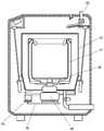
- FIG. 7 is a cross-sectional view showing a schematic structure of a conventional washing machine.
- the conventional washing machine 40 includes a washing / dehydrating tub 41, a stirring blade 42 disposed on the bottom surface of the washing / dehydrating tub 41, and outside the washing / dehydrating tub 41 and the stirring wing 42. And a water tank 43 disposed therein.
- a clutch device 44 is attached to the bottom surface of the water tank 43. By connecting the motor 45 and the clutch device 44 by the belt 46, the rotational force of the motor 45 is transmitted to the stirring blade 42 and the washing / dehydrating tub 41 via the clutch device 44.
- the clutch device 44 is switched to transmit the rotational force of the motor 45 to the stirring blade 42 during washing and to the washing and dewatering tank 41 during dehydration.
- FIG. 8 is a perspective view showing a schematic external shape of a motor used in a conventional washing machine.
- the outer shell of the motor 45 is formed of a resin mold body 54 and is fixed to the bottom surface of the water tank 43 shown in FIG. 7 via a fixing portion 55 integrally formed with the resin mold body 54.
- the resin mold body 54 is provided with a power supply terminal 56 for supplying power to the motor 45, and the motor rotation shaft 64 is rotated by supplying power to the power supply terminal 56.
- a pulley (not shown) is attached to the motor rotating shaft 64, and the rotational force is transmitted to the clutch device 44 via the belt 46 shown in FIG.
- the volume of the motor 45 increases, so the cost increases. Furthermore, since the dimensions of the motor 45 can be changed only within the limits of the dimensions of the bottom surface of the washing machine 40 shown in FIG. 7 and the dimensions of the clutch device 44 and the water tank 41, the performance of the motor 45 can be improved. There was a limit.
- the motor of the present invention winds a winding through an insulator around a tooth of a stator core composed of a substantially annular yoke and a tooth extending radially from the yoke to the inner peripheral side, and the stator core, the insulator, and the winding are resin-molded.
- a stator molded by a body, a rotor core rotatably held on the inner peripheral side of the stator via a gap, a motor rotating shaft inserted in the center of the rotor core, and a permanent magnet inserted in the rotor core in the axial direction
- the rotor which consists of.
- Concave portions and convex portions extending in the axial direction are alternately formed on the outer peripheral surface of the resin mold body, and the concave portions are arranged on the outer peripheral surface of the resin mold body extending in the outer peripheral direction from the teeth around which the windings are wound. Set up.
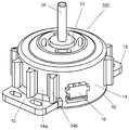
- FIG. 1 is a perspective view showing a schematic appearance of the washing machine motor according to Embodiment 1 of the present invention.
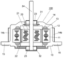
- FIG. 2 is a sectional view showing a schematic structure of the washing machine motor according to Embodiment 1 of the present invention.
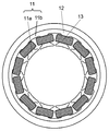
- FIG. 3 is a diagram showing a winding form of the washing machine motor according to Embodiment 1 of the present invention.
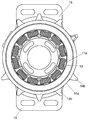
- FIG. 4 is a diagram showing a positional relationship between the recesses and the windings of the resin mold body of the washing machine motor according to Embodiment 1 of the present invention.
- FIG. 5 is a perspective view showing a schematic external shape of the washing machine motor according to Embodiment 2 of the present invention.
- FIG. 1 is a perspective view showing a schematic appearance of the washing machine motor according to Embodiment 1 of the present invention.
- FIG. 2 is a sectional view showing a schematic structure of the washing machine motor according to Embodiment 1 of the present invention.
- FIG. 3 is a diagram showing a winding
- FIG. 6 is a diagram showing a positional relationship between the recesses and windings of the resin mold body of the washing machine motor according to Embodiment 2 of the present invention.
- FIG. 7 is a sectional view showing a schematic structure of a conventional washing machine.
- FIG. 8 is a perspective view showing a schematic external shape of a conventional motor for a washing machine.
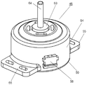
- FIG. 1 is a perspective view showing a schematic external shape of a washing machine motor according to Embodiment 1 of the present invention.
- the structure of the washing machine, the structure for fixing the motor to the washing machine, and the method of transmitting the rotational force are the same as those of the conventional washing machine shown in FIG.
- the outer shell of the motor 100 is formed of a resin mold body 14 and is integrally formed with a fixing portion 15 for fixing the motor 100 to the washing machine.
- the resin mold body 14 is provided with a power supply terminal 16 for supplying power to the motor 100, and the motor rotation shaft 24 rotates by supplying power to the power supply terminal 16.
- a pulley (not shown) is attached to the motor rotating shaft 24, and the rotational force is transmitted to the clutch device 44 via the belt 46 shown in FIG.
- outer peripheral surface concave portions 14 a and outer peripheral surface convex portions 14 b extending in the axial direction are alternately formed in order to improve heat dissipation performance.
- the outer peripheral surface concave portion 14a and the outer peripheral surface convex portion 14b can be formed over the entire circumference of the resin mold body 14, as shown in FIG.
- the number of terminals 16 can be adjusted according to the position and shape of the terminals 16.
- FIG. 2 is a cross-sectional view showing a schematic structure of the washing machine motor according to Embodiment 1 of the present invention.
- the motor 100 includes a stator 10 and a rotor 20 that is rotatably held with respect to the stator 10.
- the stator 10 includes a stator core 11 in which thin iron plates are stacked, a winding 13 wound around the stator core 11 in a radial direction, an insulator 12 that electrically insulates the stator core 11 and the winding 13, and the stator core 11, It comprises an insulator 12 and a resin mold body 14 in which the winding 13 is sealed with resin.
- the resin mold body 14 has a fixing portion 15 for fixing the motor 100 to the washing machine.
- the rotor 20 includes a rotor core 21 in which thin iron plates are stacked, and a permanent magnet 22 inserted into the rotor core 21.
- a motor rotating shaft 24 is inserted in the center of the rotor core 21, and a bearing 23 is attached to the motor rotating shaft 24.
- Bearing housings 31 and 32 are fixed to the resin mold body 14. By inserting and fixing the bearing 23 in the bearing housings 31 and 32, the rotor 20 is held rotatably with respect to the stator 10.
- the motor rotating shaft 24 rotates by applying an appropriate current to the winding 13 according to the position of the permanent magnet 22.
- current is supplied using a drive unit (not shown) such as an inverter.
- a drive unit such as an inverter.
- FIG. 3 is a diagram showing a winding form of the washing machine motor according to the first embodiment of the present invention.
- FIG. 3 shows a state in which the winding 13 is wound around the stator core 11 of FIG.
- the stator core 11 includes a substantially annular yoke 11b and teeth 11a extending radially from the yoke 11b to the inner peripheral side.
- the winding form of the motor 100 shown in FIG. 3 is a winding form generally called concentrated winding, and the winding 13 is wound around the teeth 11 a of the stator core 11.
- FIG. 4 is a diagram showing a positional relationship between the recesses and the windings of the resin mold body of the washing machine motor according to the first embodiment of the present invention.
- FIG. 4 shows the positional relationship between the winding 13 shown in FIG. 3 and the outer peripheral surface concave portion 14 a and the outer peripheral surface convex portion 14 b of the resin mold body 14.
- outer peripheral surface concave portions 14 a and outer peripheral surface convex portions 14 b extending in the axial direction are alternately formed on the outer peripheral surface of the resin mold body 14.
- the outer peripheral surface convex portion 14b By disposing the outer peripheral surface convex portion 14b, the surface area of the outer peripheral surface of the resin mold body 14 can be easily increased, so that the heat dissipation can be improved.
- an outer peripheral surface concave portion 14a in a portion extending in the outer peripheral direction from the tooth 11a around which the winding 13 is wound, heat is dissipated from the winding 13 as a heat source to the air layer through the tooth 11a. It becomes easy to do. Accordingly, it is possible to improve the heat dissipation from the outer peripheral surface of the resin mold body 14 without causing the heat generated from the winding 13 to spread to the resin mold body 14.
- the outer peripheral surface concave portions 14a and the outer peripheral surface convex portions 14b extending in the axial direction are alternately formed on the outer peripheral surface of the resin mold body 14, and extended from the teeth 11a around which the windings 13 are wound in the outer peripheral direction.
- the outer peripheral surface recessed part 14a is arrange
- FIG. 5 is a perspective view showing a schematic external shape of the washing machine motor according to Embodiment 2 of the present invention.
- the structure of the washing machine, the structure for fixing the motor to the washing machine, and the method of transmitting the rotational force are the same as those of the conventional washing machine shown in FIG. Is omitted.
- the outer shell of the motor 200 is formed of a resin mold body 14 and is integrally formed with a fixing portion 15 for fixing the motor 200 to the washing machine.
- the resin mold body 14 is provided with a power supply terminal 16 for supplying power to the motor 200, and the motor rotating shaft 24 rotates by supplying power to the power supply terminal 16.
- a pulley (not shown) is attached to the motor rotating shaft 24, and the rotational force is transmitted to the clutch device 44 via the belt 46 shown in FIG.
- outer peripheral surface concave portions 14 a and outer peripheral surface convex portions 14 b extending in the axial direction are alternately formed in order to improve heat dissipation performance.
- end surface concave portions 14c and end surface convex portions 14d extending in the radial direction are alternately formed on the end surface in the axial direction of the resin mold body 14.
- the end surface recesses 14c and the end surface protrusions 14d are preferably formed over the entire circumference of the end surface in the axial direction of the resin mold body 14, but the number of the end surface recesses 14c and the end surface protrusions 14d may be reduced.
- the structure and winding form of the motor 200 of the second embodiment shown in FIG. 5 are the same as those of the motor 100 of the first embodiment shown in FIGS.
- FIG. 6 is a diagram showing the positional relationship between the recesses and the windings of the resin mold body of the washing machine motor according to Embodiment 2 of the present invention.
- FIG. 6 shows the positional relationship between the outer peripheral surface concave portion 14 a, the outer peripheral surface convex portion 14 b, the end surface concave portion 14 c, the end surface convex portion 14 d of the resin mold body 14 and the winding 13.
- outer peripheral surface concave portions 14 a and outer peripheral surface convex portions 14 b extending in the axial direction are alternately formed on the outer peripheral surface of the resin mold body 14, and the axial end surface of the resin mold body 14 has a diameter on the end surface.
- End surface concave portions 14c and end surface convex portions 14d extending in the direction are alternately formed.
- the arrangement and effects of the outer peripheral surface concave portion 14a and the outer peripheral surface convex portion 14b are the same as those shown in the first embodiment.
- the surface area on the end surface of the resin mold body 14 can also increase easily by arrange
- the end surface recess 14c in the portion extending in the axial direction from the winding 13, the distance between the winding 13 serving as a heat source and the air layer where heat is dissipated can be shortened. Thereby, it is possible to improve the heat dissipation from both the outer peripheral surface and the axial end surface of the resin mold body 14 without causing the heat generated from the winding 13 to spread to the resin mold body 14.
- the heat conductivity of the resin material normally used is about 1.1 W / m ⁇ K, but if it is 1.4 W / m ⁇ K or more, the winding 13 and The thermal conductivity between the outer peripheral surface concave portion 14a and the end surface concave portion 14c is improved. As a result, it is further difficult to generate heat inside the resin mold body 14, and the heat dissipation performance can be improved.
- the outer peripheral surface concave portions 14a and the outer peripheral surface convex portions 14b extending in the axial direction are alternately formed on the outer peripheral surface of the resin mold body 14, and extended from the teeth 11a around which the windings 13 are wound in the outer peripheral direction.
- the outer peripheral surface recessed part 14a is arrange
- end surface recesses 14c and end surface protrusions 14d extending in the radial direction are alternately formed on the end surface in the axial direction of the resin mold body 14, and the end surface recesses 14c are disposed at portions extending from the windings 13 in the axial direction.
- the thermal conductivity of the resin material constituting the resin mold body 14 is 1.4 W / m ⁇ K or more, the thermal conductivity between the winding 13 and the outer peripheral surface concave portion 14a and the end surface concave portion 14c is improved. To do. As a result, it is further difficult to generate heat inside the resin mold body 14, and the heat dissipation performance can be improved.
- the structure is shown as an inner rotor type motor in which a rotor is disposed on the inner periphery of the stator.
- an outer rotor type in which a rotor is disposed on the outer periphery of the stator, or a gap in the axial direction from the stator.
- the same effect can be obtained by disposing the above-described recess in a portion that does not interfere with the rotor.
- the motor according to the present invention winds a winding around a stator core tooth including a substantially annular yoke and a tooth extending radially from the yoke to the inner peripheral side via an insulator.
- recesses and projections extending in the axial direction are alternately formed, and the recesses are disposed on the outer peripheral surface of the resin mold body extending from the teeth around which the windings are wound. To do.
- heat dissipation from the winding as a heat source is increased while increasing the heat dissipation area by changing only the shape of the resin mold body without increasing the dimension of the motor in the axial direction and without changing the stator core. Therefore, the heat dissipation performance can be improved.
- recesses and protrusions extending in the radial direction are alternately formed on the axial end surface of the resin mold body, and the recesses are formed on the axial end surface of the resin mold body extending in the axial direction from the winding. Is disposed.
- the thermal conductivity of the resin material constituting the resin mold body is set to 1.4 W / m ⁇ K or more.
- the thermal conductivity between the winding and the concave portion of the resin mold body is improved compared to the thermal conductivity of the resin material that is normally used, and it is difficult for heat to flow inside the resin mold body. Therefore, the motor performance can be improved.
- the motor according to the present invention is typified by a washing machine because it can improve the heat dissipation performance without excessively increasing the size of the motor or increasing the cost, and can provide a small and high-performance motor. Suitable for applications that require small size and high performance in home appliances.
Abstract
Description
図1は、本発明の実施の形態1における洗濯機用モータの概略外観形状を示す斜視図である。尚、洗濯機の構造や、モータの洗濯機への固定構造、回転力の伝達方法は図7に示した従来の洗濯機と同様であるため、ここでは説明を省略する。 (Embodiment 1)
FIG. 1 is a perspective view showing a schematic external shape of a washing machine motor according to Embodiment 1 of the present invention. The structure of the washing machine, the structure for fixing the motor to the washing machine, and the method of transmitting the rotational force are the same as those of the conventional washing machine shown in FIG.
図5は、本発明の実施の形態2における洗濯機用モータの概略外観形状を示す斜視図である。尚、実施の形態1と同様に、洗濯機の構造や、モータの洗濯機への固定構造、回転力の伝達方法は、図7に示した従来の洗濯機と同様であるため、ここでは説明を省略する。 (Embodiment 2)
FIG. 5 is a perspective view showing a schematic external shape of the washing machine motor according to Embodiment 2 of the present invention. As in the first embodiment, the structure of the washing machine, the structure for fixing the motor to the washing machine, and the method of transmitting the rotational force are the same as those of the conventional washing machine shown in FIG. Is omitted.
11 ステータコア
11a ティース
11b ヨーク
12 絶縁物
13 巻線
14 樹脂モールド体
14a 外周面凹部
14b 外周面凸部
14c 端面凹部
14d 端面凸部
15 固定部
16 電源端子
20 ロータ
21 ロータコア
22 永久磁石
23 軸受
24 モータ回転軸
31,32 軸受ハウジング
100,200 モータ DESCRIPTION OF
Claims (3)
- 略環状のヨークと前記ヨークから内周側へ径方向に延びるティースとからなるステータコアの前記ティースに絶縁物を介して巻線を巻回し、前記ステータコア、前記絶縁物、前記巻線を樹脂モールド体によってモールド成形したステータと、
前記ステータの内周側に空隙を介して回転自在に保持されたロータコアと、前記ロータコアの中央に挿入されたモータ回転軸と、前記ロータコアに軸方向に挿入された永久磁石とからなるロータと、
を有するモータであって、
前記樹脂モールド体における外周面に、軸方向に延びる凹部と凸部とを交互に形成し、前記巻線を巻回した前記ティースから外周方向に伸延した部分の前記樹脂モールド体の外周面に前記凹部を配設したことを特徴としたモータ。 A winding is wound around the teeth of a stator core formed of a substantially annular yoke and teeth extending radially inward from the yoke via an insulator, and the stator core, the insulator, and the winding are resin-molded. A stator molded by
A rotor core that is rotatably held on the inner peripheral side of the stator via a gap, a motor rotation shaft inserted in the center of the rotor core, and a permanent magnet inserted in the rotor core in the axial direction;
A motor having
On the outer peripheral surface of the resin mold body, recesses and protrusions extending in the axial direction are alternately formed, and the outer peripheral surface of the resin mold body is extended from the teeth wound with the winding in the outer peripheral direction. A motor characterized in that a recess is provided. - 前記樹脂モールド体における軸方向端面に、径方向に延びる凹部と凸部とを交互に形成し、前記巻線から軸方向に伸延した部分の前記樹脂モールド体の軸方向端面に前記凹部を配設したことを特徴とした請求項1に記載のモータ。 On the end surface in the axial direction of the resin mold body, recesses and projections extending in the radial direction are alternately formed, and the recesses are disposed on the end surface in the axial direction of the resin mold body extending in the axial direction from the winding. The motor according to claim 1, wherein
- 前記樹脂モールド体を構成する樹脂材料の熱伝導率が1.4W/m・K以上であることを特徴とした請求項1あるいは請求項2のいずれか1項に記載のモータ。 3. The motor according to claim 1, wherein a thermal conductivity of a resin material constituting the resin mold body is 1.4 W / m · K or more.
Priority Applications (5)
| Application Number | Priority Date | Filing Date | Title |
|---|---|---|---|
| PCT/JP2012/003951 WO2013190588A1 (en) | 2012-06-18 | 2012-06-18 | Motor |
| JP2012548257A JP5288065B1 (en) | 2012-06-18 | 2012-06-18 | motor |
| CN201280074047.1A CN104412490B (en) | 2012-06-18 | 2012-06-18 | Motor |
| EP12879589.5A EP2863516B1 (en) | 2012-06-18 | 2012-06-18 | Motor |
| US14/406,611 US9716417B2 (en) | 2012-06-18 | 2012-06-18 | Motor |
Applications Claiming Priority (1)
| Application Number | Priority Date | Filing Date | Title |
|---|---|---|---|
| PCT/JP2012/003951 WO2013190588A1 (en) | 2012-06-18 | 2012-06-18 | Motor |
Publications (1)
| Publication Number | Publication Date |
|---|---|
| WO2013190588A1 true WO2013190588A1 (en) | 2013-12-27 |
Family
ID=49274082
Family Applications (1)
| Application Number | Title | Priority Date | Filing Date |
|---|---|---|---|
| PCT/JP2012/003951 WO2013190588A1 (en) | 2012-06-18 | 2012-06-18 | Motor |
Country Status (5)
| Country | Link |
|---|---|
| US (1) | US9716417B2 (en) |
| EP (1) | EP2863516B1 (en) |
| JP (1) | JP5288065B1 (en) |
| CN (1) | CN104412490B (en) |
| WO (1) | WO2013190588A1 (en) |
Cited By (1)
| Publication number | Priority date | Publication date | Assignee | Title |
|---|---|---|---|---|
| EP3198705A4 (en) * | 2014-07-21 | 2017-12-27 | Prime Datum Development Company, LLC | Power dense motor with thermal management capability |
Families Citing this family (11)
| Publication number | Priority date | Publication date | Assignee | Title |
|---|---|---|---|---|
| DE102014223804A1 (en) * | 2014-11-21 | 2016-05-25 | Robert Bosch Gmbh | Electric machine with mounting flange |
| EP3316455A4 (en) * | 2015-06-29 | 2018-06-13 | Guangdong Welling Motor Manufacturing Co., Ltd. | Motor, washing pump, dishwasher and motor manufacturing method |
| US20180062457A1 (en) * | 2016-08-31 | 2018-03-01 | Hamilton Sundstrand Corporation | Switched reluctance motor with axial laminated construction |
| JP1580863S (en) * | 2017-02-14 | 2017-07-10 | ||
| USD871346S1 (en) * | 2018-07-08 | 2019-12-31 | Every Industry Llc | Explosion-proof junction box |
| JP1653124S (en) * | 2019-06-20 | 2020-02-17 | ||
| JP1653125S (en) * | 2019-06-20 | 2020-02-17 | ||
| USD915279S1 (en) * | 2019-06-20 | 2021-04-06 | Panasonic Intellectual Property Management Co., Ltd. | Motor |
| USD917394S1 (en) * | 2019-12-31 | 2021-04-27 | Theragun, Inc. | Motor |
| USD920910S1 (en) * | 2019-12-31 | 2021-06-01 | Theragun, Inc. | Motor |
| USD919573S1 (en) * | 2019-12-31 | 2021-05-18 | Theragun, Inc. | Motor |
Citations (5)
| Publication number | Priority date | Publication date | Assignee | Title |
|---|---|---|---|---|
| JPH07298538A (en) * | 1994-04-28 | 1995-11-10 | Matsushita Electric Ind Co Ltd | Stator for motor |
| JPH08140300A (en) * | 1994-11-07 | 1996-05-31 | Asmo Co Ltd | Motor with radiation fins |
| JP2004320991A (en) | 2003-03-31 | 2004-11-11 | Matsushita Electric Ind Co Ltd | Motor |
| JP2008194264A (en) | 2007-02-14 | 2008-08-28 | Matsushita Electric Ind Co Ltd | Motor |
| JP2008228423A (en) * | 2007-03-12 | 2008-09-25 | Matsushita Electric Ind Co Ltd | Motor |
Family Cites Families (13)
| Publication number | Priority date | Publication date | Assignee | Title |
|---|---|---|---|---|
| GB2172444B (en) * | 1985-03-09 | 1988-08-17 | Asmo Co Ltd | Stator for an electric motor |
| US4823032A (en) | 1988-08-01 | 1989-04-18 | General Motors Corporation | End frame and stator assembly for a dynamoelectric machine |
| US5331238A (en) | 1993-03-01 | 1994-07-19 | Sundstrand Corporation | Apparatus for containment and cooling of a core within a housing |
| US5757096A (en) * | 1995-09-12 | 1998-05-26 | Dubois; Randy P. | Alternator cooling device |
| JPH10271720A (en) * | 1997-03-21 | 1998-10-09 | Matsushita Electric Ind Co Ltd | Stator in mold motor |
| JP3775348B2 (en) * | 2002-05-31 | 2006-05-17 | 株式会社日立製作所 | Rotating electric machine |
| JP2006043153A (en) * | 2004-08-04 | 2006-02-16 | Nidec Shibaura Corp | Washing machine |
| WO2006048951A1 (en) * | 2004-11-04 | 2006-05-11 | Matsushita Electric Industrial Co., Ltd. | Motor and electric apparatus using the same motor |
| TWI382634B (en) * | 2004-12-15 | 2013-01-11 | Panasonic Corp | Motor with double insulation structure and electric apparatus using the same motor |
| US20070152523A1 (en) * | 2005-12-12 | 2007-07-05 | Franklin Electric Co., Inc. | Submersible Motor with molded encapsulated stator |
| JP4661849B2 (en) * | 2007-09-27 | 2011-03-30 | トヨタ自動車株式会社 | Stator structure |
| CN101771298A (en) * | 2008-12-26 | 2010-07-07 | 三洋电机株式会社 | Molded motor and electric vehicle |
| WO2012017646A1 (en) * | 2010-08-03 | 2012-02-09 | パナソニック株式会社 | Molded structure and motor comprising same |
-
2012
- 2012-06-18 US US14/406,611 patent/US9716417B2/en not_active Expired - Fee Related
- 2012-06-18 EP EP12879589.5A patent/EP2863516B1/en not_active Not-in-force
- 2012-06-18 CN CN201280074047.1A patent/CN104412490B/en active Active
- 2012-06-18 JP JP2012548257A patent/JP5288065B1/en active Active
- 2012-06-18 WO PCT/JP2012/003951 patent/WO2013190588A1/en active Application Filing
Patent Citations (6)
| Publication number | Priority date | Publication date | Assignee | Title |
|---|---|---|---|---|
| JPH07298538A (en) * | 1994-04-28 | 1995-11-10 | Matsushita Electric Ind Co Ltd | Stator for motor |
| JPH08140300A (en) * | 1994-11-07 | 1996-05-31 | Asmo Co Ltd | Motor with radiation fins |
| JP2004320991A (en) | 2003-03-31 | 2004-11-11 | Matsushita Electric Ind Co Ltd | Motor |
| JP2008194264A (en) | 2007-02-14 | 2008-08-28 | Matsushita Electric Ind Co Ltd | Motor |
| JP2008228423A (en) * | 2007-03-12 | 2008-09-25 | Matsushita Electric Ind Co Ltd | Motor |
| JP4339900B2 (en) | 2007-03-12 | 2009-10-07 | パナソニック株式会社 | motor |
Non-Patent Citations (1)
| Title |
|---|
| See also references of EP2863516A4 |
Cited By (1)
| Publication number | Priority date | Publication date | Assignee | Title |
|---|---|---|---|---|
| EP3198705A4 (en) * | 2014-07-21 | 2017-12-27 | Prime Datum Development Company, LLC | Power dense motor with thermal management capability |
Also Published As
| Publication number | Publication date |
|---|---|
| CN104412490A (en) | 2015-03-11 |
| CN104412490B (en) | 2017-02-22 |
| JP5288065B1 (en) | 2013-09-11 |
| US9716417B2 (en) | 2017-07-25 |
| EP2863516A4 (en) | 2016-04-13 |
| US20150249376A1 (en) | 2015-09-03 |
| EP2863516B1 (en) | 2018-01-03 |
| JPWO2013190588A1 (en) | 2016-02-08 |
| EP2863516A1 (en) | 2015-04-22 |
Similar Documents
| Publication | Publication Date | Title |
|---|---|---|
| JP5288065B1 (en) | motor | |
| JP5642291B2 (en) | Rotating electric machine | |
| JP5288064B1 (en) | motor | |
| JP5649737B2 (en) | Mechanical and electrical integrated module | |
| US7830064B2 (en) | Motor and drum washing machine having the same | |
| WO2015181889A1 (en) | Rotating electric machine | |
| JP6199057B2 (en) | Electric motor | |
| JP2016144394A (en) | Electric motor | |
| JP6084561B2 (en) | Rotating electric machine | |
| TWI673936B (en) | Axial gap type rotary motor | |
| KR102472089B1 (en) | BLDC Motor for Laundry Dryer | |
| CN210183136U (en) | Motor and outer rotor used by same | |
| JP2018026920A (en) | motor | |
| JP2013059526A (en) | Brushless motor for washing machine | |
| CN102332779A (en) | Motor cooling structure of electric vehicle | |
| JP4476942B2 (en) | Induction motor and ventilator | |
| CN220309022U (en) | Food processor with stable structure | |
| CN202309277U (en) | Brushless motor | |
| JP5193547B2 (en) | Permanent magnet type rotating electric machine for washing machine | |
| JP2002330559A (en) | Motor | |
| KR20220129695A (en) | Rotor with structure to reduce overhang magnetic path and permanent magnet motor including the same | |
| JP2010239725A (en) | Rotary electric machine for vehicle | |
| KR20130003294A (en) | Double rotor type motor and washing machine having the same | |
| JP2021078194A (en) | Electric actuator | |
| JP2005176471A (en) | Stator of rotary electric machine |
Legal Events
| Date | Code | Title | Description |
|---|---|---|---|
| ENP | Entry into the national phase |
Ref document number: 2012548257 Country of ref document: JP Kind code of ref document: A |
|
| 121 | Ep: the epo has been informed by wipo that ep was designated in this application |
Ref document number: 12879589 Country of ref document: EP Kind code of ref document: A1 |
|
| WWE | Wipo information: entry into national phase |
Ref document number: 2012879589 Country of ref document: EP |
|
| NENP | Non-entry into the national phase |
Ref country code: DE |
|
| WWE | Wipo information: entry into national phase |
Ref document number: 14406611 Country of ref document: US |