WO2013187072A1 - Dispositifs pour envoyer et recevoir des informations de rétroaction - Google Patents
Dispositifs pour envoyer et recevoir des informations de rétroaction Download PDFInfo
- Publication number
- WO2013187072A1 WO2013187072A1 PCT/JP2013/003733 JP2013003733W WO2013187072A1 WO 2013187072 A1 WO2013187072 A1 WO 2013187072A1 JP 2013003733 W JP2013003733 W JP 2013003733W WO 2013187072 A1 WO2013187072 A1 WO 2013187072A1
- Authority
- WO
- WIPO (PCT)
- Prior art keywords
- serving cell
- harq
- feedback
- ack
- configuration
- Prior art date
Links
Images


Classifications
-
- H—ELECTRICITY
- H04—ELECTRIC COMMUNICATION TECHNIQUE
- H04L—TRANSMISSION OF DIGITAL INFORMATION, e.g. TELEGRAPHIC COMMUNICATION
- H04L1/00—Arrangements for detecting or preventing errors in the information received
- H04L1/12—Arrangements for detecting or preventing errors in the information received by using return channel
- H04L1/16—Arrangements for detecting or preventing errors in the information received by using return channel in which the return channel carries supervisory signals, e.g. repetition request signals
- H04L1/18—Automatic repetition systems, e.g. Van Duuren systems
- H04L1/1829—Arrangements specially adapted for the receiver end
- H04L1/1854—Scheduling and prioritising arrangements
-
- H—ELECTRICITY
- H04—ELECTRIC COMMUNICATION TECHNIQUE
- H04B—TRANSMISSION
- H04B7/00—Radio transmission systems, i.e. using radiation field
- H04B7/24—Radio transmission systems, i.e. using radiation field for communication between two or more posts
- H04B7/26—Radio transmission systems, i.e. using radiation field for communication between two or more posts at least one of which is mobile
- H04B7/2612—Arrangements for wireless medium access control, e.g. by allocating physical layer transmission capacity
-
- H—ELECTRICITY
- H04—ELECTRIC COMMUNICATION TECHNIQUE
- H04L—TRANSMISSION OF DIGITAL INFORMATION, e.g. TELEGRAPHIC COMMUNICATION
- H04L1/00—Arrangements for detecting or preventing errors in the information received
- H04L1/12—Arrangements for detecting or preventing errors in the information received by using return channel
- H04L1/16—Arrangements for detecting or preventing errors in the information received by using return channel in which the return channel carries supervisory signals, e.g. repetition request signals
- H04L1/18—Automatic repetition systems, e.g. Van Duuren systems
- H04L1/1867—Arrangements specially adapted for the transmitter end
- H04L1/1887—Scheduling and prioritising arrangements
-
- H—ELECTRICITY
- H04—ELECTRIC COMMUNICATION TECHNIQUE
- H04B—TRANSMISSION
- H04B7/00—Radio transmission systems, i.e. using radiation field
- H04B7/24—Radio transmission systems, i.e. using radiation field for communication between two or more posts
- H04B7/26—Radio transmission systems, i.e. using radiation field for communication between two or more posts at least one of which is mobile
- H04B7/2643—Radio transmission systems, i.e. using radiation field for communication between two or more posts at least one of which is mobile using time-division multiple access [TDMA]
-
- H—ELECTRICITY
- H04—ELECTRIC COMMUNICATION TECHNIQUE
- H04L—TRANSMISSION OF DIGITAL INFORMATION, e.g. TELEGRAPHIC COMMUNICATION
- H04L1/00—Arrangements for detecting or preventing errors in the information received
- H04L1/12—Arrangements for detecting or preventing errors in the information received by using return channel
- H04L1/16—Arrangements for detecting or preventing errors in the information received by using return channel in which the return channel carries supervisory signals, e.g. repetition request signals
- H04L1/18—Automatic repetition systems, e.g. Van Duuren systems
- H04L1/1812—Hybrid protocols; Hybrid automatic repeat request [HARQ]
-
- H—ELECTRICITY
- H04—ELECTRIC COMMUNICATION TECHNIQUE
- H04L—TRANSMISSION OF DIGITAL INFORMATION, e.g. TELEGRAPHIC COMMUNICATION
- H04L1/00—Arrangements for detecting or preventing errors in the information received
- H04L1/12—Arrangements for detecting or preventing errors in the information received by using return channel
- H04L1/16—Arrangements for detecting or preventing errors in the information received by using return channel in which the return channel carries supervisory signals, e.g. repetition request signals
- H04L1/18—Automatic repetition systems, e.g. Van Duuren systems
- H04L1/1867—Arrangements specially adapted for the transmitter end
- H04L1/1893—Physical mapping arrangements
-
- H—ELECTRICITY
- H04—ELECTRIC COMMUNICATION TECHNIQUE
- H04L—TRANSMISSION OF DIGITAL INFORMATION, e.g. TELEGRAPHIC COMMUNICATION
- H04L5/00—Arrangements affording multiple use of the transmission path
- H04L5/003—Arrangements for allocating sub-channels of the transmission path
- H04L5/0053—Allocation of signaling, i.e. of overhead other than pilot signals
- H04L5/0055—Physical resource allocation for ACK/NACK
-
- H—ELECTRICITY
- H04—ELECTRIC COMMUNICATION TECHNIQUE
- H04L—TRANSMISSION OF DIGITAL INFORMATION, e.g. TELEGRAPHIC COMMUNICATION
- H04L1/00—Arrangements for detecting or preventing errors in the information received
- H04L1/12—Arrangements for detecting or preventing errors in the information received by using return channel
- H04L1/16—Arrangements for detecting or preventing errors in the information received by using return channel in which the return channel carries supervisory signals, e.g. repetition request signals
- H04L1/18—Automatic repetition systems, e.g. Van Duuren systems
- H04L1/1829—Arrangements specially adapted for the receiver end
- H04L1/1861—Physical mapping arrangements
-
- H—ELECTRICITY
- H04—ELECTRIC COMMUNICATION TECHNIQUE
- H04W—WIRELESS COMMUNICATION NETWORKS
- H04W72/00—Local resource management
- H04W72/04—Wireless resource allocation
- H04W72/044—Wireless resource allocation based on the type of the allocated resource
- H04W72/0446—Resources in time domain, e.g. slots or frames
Definitions
- the present disclosure relates generally to communication systems. More specifically, the present disclosure relates to devices for sending and receiving feedback information.
- a wireless communication system may provide communication for a number of wireless communication devices, each of which may be serviced by a base station.
- a base station may be a device that communicates with wireless communication devices.
- wireless communication devices may communicate with one or more devices using a communication structure.
- the communication structure used may only offer limited flexibility and/or efficiency.
- systems and methods that improve communication flexibility and/or efficiency may be beneficial.
- a method for sending feedback information by a User Equipment includes determining a Time-Division Duplexing (TDD) uplink-downlink (UL-DL) configurations of each of serving cell c, wherein the TDD UL-DL configuration of at least two configured serving cells is not the same.
- TDD Time-Division Duplexing
- UL-DL uplink-downlink
- the method also includes determining first feedback factors for the each serving cell based on a parameter M c , if a Physical Uplink Shared Channel (PUSCH) transmission adjusted based on an detected Downlink Control Information (DCI) format 0/4 for a serving cell with a UL/DL configuration 0, wherein the first feedback factor is the number of downlink subframes for which the UE needs to feedback HARQ-ACK bits for the c-th serving cell, and M c is the number of elements in a set K c , the set K c includes one or more values of k of the c-th serving cell, wherein Hybrid Automatic Repeat Request Acknowledgement/Negative Acknowledgement (HARQ-ACK) in the subframe n corresponds to a Physical Downlink Shared Channel (PDSCH) in subframe n-k.
- the method further includes sending HARQ-ACK information on the PUSCH based on the first feedback factors .
- a method for sending feedback information by a User Equipment includes determining a Time-Division Duplexing (TDD) uplink-downlink (UL-DL) configurations of each of serving cell c, wherein the TDD UL-DL configuration of at least two configured serving cells is not the same.
- TDD Time-Division Duplexing
- UL-DL uplink-downlink
- the method also includes determining first feedback factors for the each serving cell based on , if a timing reference UL/DL configuration of at least one configured serving cell belongs to ⁇ 5 ⁇ and a Physical Uplink Shared Channel (PUSCH) transmission adjusted based on an detected DCI format 0/4 for a serving cell, wherein the first feedback factor is the number of downlink subframes for which the UE needs to feedback HARQ-ACK bits for the c-th serving cell, and M c is the number of elements in a set K c , the set K c includes one or more values of k of the c-th serving cell, wherein Hybrid Automatic Repeat Request Acknowledgement/Negative Acknowledgement (HARQ-ACK) in the subframe n corresponds to a Physical Downlink Shared Channel (PDSCH) in subframe n-k, and denotes a maximum value of among all configured serving cells, where is the total number of received Physical Downlink Shared Channels (PDSCHs) and Physical Downlink Control Channel (PDCCH)
- the UE includes an operations unit configured to determine a Time-Division Duplexing (TDD) uplink-downlink (UL-DL) configurations of each of serving cell c, wherein the TDD UL-DL configuration of at least two configured serving cells is not the same, and to determine first feedback factors for the each serving cell based on a parameter M c , if a Physical Uplink Shared Channel (PUSCH) transmission adjusted based on an detected Downlink Control Information (DCI) format 0/4 for a serving cell with a UL/DL configuration 0, wherein the first feedback factor is the number of downlink subframes for which the UE needs to feedback HARQ-ACK bits for the c-th serving cell, and M c is the number of elements in a set K c , the set K c includes one or more values of k of the c-th serving cell, wherein Hybrid Automatic Repeat Request Acknowledgement/Negative Acknowledgement (HARQ-ACK) in the
- TDD Time-Division Duplexing
- the UE includes an operations unit configured to determine a Time-Division Duplexing (TDD) uplink-downlink (UL-DL) configurations of each of serving cell c, wherein the TDD UL-DL configuration of at least two configured serving cells is not the same, and to determine first feedback factors for the each serving cell based on , if a timing reference UL/DL configuration of at least one configured serving cell belongs to ⁇ 5 ⁇ and a Physical Uplink Shared Channel (PUSCH) transmission adjusted based on an detected DCI format 0/4 for a serving cell, wherein the first feedback factor is the number of downlink subframes for which the UE needs to feedback HARQ-ACK bits for the c-th serving cell, and M c is the number of elements in a set K c , the set K c includes one or more values of k of the c-th serving cell, wherein Hybrid Automatic Repeat Request Acknowledgement/Negative Acknowledgement (HARQ-ACK
- HARQ-ACK Hybrid Automatic Repeat
- An integrated circuit mounted on a UE for causing the UE to perform a plurality of functions is described.
- the integrated circuit causing the UE to perform determining a Time-Division Duplexing (TDD) uplink-downlink (UL-DL) configurations of each of serving cell c, wherein the TDD UL-DL configuration of at least two configured serving cells is not the same.
- TDD Time-Division Duplexing
- UL-DL uplink-downlink
- the integrated circuit causing the UE to perform also determining first feedback factors for the each serving cell based on a parameter M c , if a Physical Uplink Shared Channel (PUSCH) transmission adjusted based on an detected DCI format 0/4 for a serving cell with a UL/DL configuration 0, wherein the first feedback factor is the number of downlink subframes for which the UE needs to feedback HARQ-ACK bits for the c-th serving cell, and M c is the number of elements in a set K c , the set K c includes one or more values of k of the c-th serving cell, wherein Hybrid Automatic Repeat Request Acknowledgement/Negative Acknowledgement (HARQ-ACK) in the subframe n corresponds to a Physical Downlink Shared Channel (PDSCH) in subframe n-k.
- the integrated circuit causing the UE to perform further sending HARQ-ACK information on the PUSCH based on the first feedback factors .
- An integrated circuit mounted on a UE for causing the UE to perform a plurality of functions is described.
- the integrated circuit causing the UE to perform determining a Time-Division Duplexing (TDD) uplink-downlink (UL-DL) configurations of each of serving cell c, wherein the TDD UL-DL configuration of at least two configured serving cells is not the same.
- TDD Time-Division Duplexing
- UL-DL uplink-downlink
- the integrated circuit causing the UE to perform also determining first feedback factors for the each serving cell based on , if a timing reference UL/DL configuration of at least one configured serving cell belongs to ⁇ 5 ⁇ and a Physical Uplink Shared Channel (PUSCH) transmission adjusted based on an detected DCI format 0/4 for a serving cell, wherein the first feedback factor is the number of downlink subframes for which the UE needs to feedback HARQ-ACK bits for the c-th serving cell, and M c is the number of elements in a set K c , the set K c includes one or more values of k of the c-th serving cell, wherein Hybrid Automatic Repeat Request Acknowledgement/Negative Acknowledgement (HARQ-ACK) in the subframe n corresponds to a Physical Downlink Shared Channel (PDSCH) in subframe n-k, and denotes a maximum value of among all configured serving cells, where is the total number of received Physical Downlink Shared Channels (PDSCHs) and Physical Downlink
- a method for receiving feedback information by an evolved Node B includes determining a Time-Division Duplexing (TDD) uplink-downlink (UL-DL) configurations of each of serving cell c for a User Equipment (UE), wherein the TDD UL-DL configuration of at least two configured serving cells for the UE is not the same.
- TDD Time-Division Duplexing
- UL-DL uplink-downlink
- the method also includes receiving Hybrid Automatic Repeat Request Acknowledgement/Negative Acknowledgement (HARQ-ACK) information on a Physical Uplink Shared Channel (PUSCH) based on first feedback factors ; wherein the first feedback factors for the each serving cell are determined based on a parameter M c , if the PUSCH transmission adjusted based on an detected Downlink Control Information (DCI) format 0/4 for a serving cell with a UL/DL configuration 0, wherein the first feedback factor is the number of downlink subframes for which the UE needs to feedback HARQ-ACK bits for the c-th serving cell, and M c is the number of elements in a set K c , the set K c includes one or more values of k of the c-th serving cell, wherein HARQ-ACK in the subframe n corresponds to a Physical Downlink Shared Channel (PDSCH) in subframe n-k.
- DCI Downlink Control Information
- a method for receiving feedback information by an evolved Node B includes determining a Time-Division Duplexing (TDD) uplink-downlink (UL-DL) configurations of each of serving cell c for a User Equipment (UE), wherein the TDD UL-DL configuration of at least two configured serving cells for the UE is not the same.
- TDD Time-Division Duplexing
- UL-DL uplink-downlink
- the method also includes receiving Hybrid Automatic Repeat Request Acknowledgement/Negative Acknowledgement (HARQ-ACK) information on a Physical Downlink Shared Channel (PUSCH) based on first feedback factors ; wherein the first feedback factors for the each serving cell are determined based on , if a timing reference UL/DL configuration of at least one configured serving cell belongs to ⁇ 5 ⁇ and a Physical Uplink Shared Channel (PUSCH) transmission adjusted based on an detected DCI format 0/4 for a serving cell, wherein the first feedback factor is the number of downlink subframes for which the UE needs to feedback HARQ-ACK bits for the c-th serving cell, and M c is the number of elements in a set K c , the set K c includes one or more values of k of the c-th serving cell, wherein HARQ-ACK in the subframe n corresponds to a Physical Downlink Shared Channel (PDSCH) in subframe n-k, and denotes a maximum value of among all configured serving cells
- a method for receiving feedback information by an evolved Node B includes an operations unit configured to determine a Time-Division Duplexing (TDD) uplink-downlink (UL-DL) configurations of each of serving cell c for a User Equipment (UE), wherein the TDD UL-DL configuration of at least two configured serving cells for the UE is not the same.
- TDD Time-Division Duplexing
- UL-DL uplink-downlink
- the method also includes a receiving unit configured to receive Hybrid Automatic Repeat Request Acknowledgement/Negative Acknowledgement (HARQ-ACK) information on a Physical Uplink Shared Channel (PUSCH) based on first feedback factors ; wherein the first feedback factors for the each serving cell are determined based on a parameter M c , if the PUSCH transmission adjusted based on an detected Downlink Control Information (DCI) format 0/4 for a serving cell with a UL/DL configuration 0, wherein the first feedback factor is the number of downlink subframes for which the UE needs to feedback HARQ-ACK bits for the c-th serving cell, and M c is the number of elements in a set K c , the set K c includes one or more values of k of the c-th serving cell, wherein HARQ-ACK in the subframe n corresponds to a Physical Downlink Shared Channel (PDSCH) in subframe n-k.
- PDSCH Physical Downlink Shared Channel
- a method for receiving feedback information by an evolved Node B includes an operations unit configured to determine a Time-Division Duplexing (TDD) uplink-downlink (UL-DL) configurations of each of serving cell c for a User Equipment (UE), wherein the TDD UL-DL configuration of at least two configured serving cells for the UE is not the same.
- TDD Time-Division Duplexing
- UL-DL uplink-downlink
- the method also includes a receiving unit configured to receive Hybrid Automatic Repeat Request Acknowledgement/Negative Acknowledgement (HARQ-ACK) information on a Physical Uplink Shared Channel (PUSCH) based on first feedback factors ; wherein the first feedback factors for the each serving cell are determined based on , if a timing reference UL/DL configuration of at least one configured serving cell belongs to ⁇ 5 ⁇ and a PUSCH transmission adjusted based on an detected DCI format 0/4 for a serving cell, wherein the first feedback factor is the number of downlink subframes for which the UE needs to feedback HARQ-ACK bits for the c-th serving cell, and M c is the number of elements in a set K c , the set K c includes one or more values of k of the c-th serving cell, wherein HARQ-ACK in the subframe n corresponds to a Physical Downlink Shared Channel (PDSCH) in subframe n-k, and denotes a maximum value of among all configured serving cells,
- An integrated circuit mounted on an evolved Node B (eNB) for causing the eNB to perform a plurality of functions is described.
- the integrated circuit causing the eNB to perform determining a Time-Division Duplexing (TDD) uplink-downlink (UL-DL) configurations of each of serving cell c, wherein the TDD UL-DL configuration of at least two configured serving cells is not the same.
- TDD Time-Division Duplexing
- UL-DL uplink-downlink
- the integrated circuit causing the eNB to perform also receiving Hybrid Automatic Repeat Request Acknowledgement/Negative Acknowledgement (HARQ-ACK) information on a Physical Uplink Shared Channel (PUSCH) based on first feedback factors ; wherein the first feedback factors for the each serving cell based on a parameter M c , if the PUSCH transmission adjusted based on an detected Downlink Control Information (DCI) format 0/4 for a serving cell with a UL/DL configuration 0, wherein the first feedback factor is the number of downlink subframes for which the UE needs to feedback HARQ-ACK bits for the c-th serving cell, and M c is the number of elements in a set K c , the set K c includes one or more values of k of the c-th serving cell, wherein HARQ-ACK in the subframe n corresponds to a Physical Downlink Shared Channel (PDSCH) in subframe n-k.
- PDSCH Physical Downlink Shared Channel
- An integrated circuit mounted on an evolved Node B (eNB) for causing the eNB to perform a plurality of functions is described.
- the integrated circuit causing the eNB to perform determining a Time-Division Duplexing (TDD) uplink-downlink (UL-DL) configurations of each of serving cell c for a User Equipment (UE), wherein the TDD UL-DL configuration of at least two configured serving cells for the UE is not the same.
- TDD Time-Division Duplexing
- UL-DL Uplink-downlink
- the integrated circuit causing the eNB to perform also receiving Hybrid Automatic Repeat Request Acknowledgement/Negative Acknowledgement (HARQ-ACK) information on a Physical Uplink Shared Channel (PUSCH) based on first feedback factors ; wherein the first feedback factors for the each serving cell are determined based on , if a timing reference UL/DL configuration of at least one configured serving cell belongs to ⁇ 5 ⁇ and the PUSCH transmission adjusted based on an detected DCI format 0/4 for a serving cell, wherein the first feedback factor is the number of downlink subframes for which the UE needs to feedback HARQ-ACK bits for the c-th serving cell, and M c is the number of elements in a set K c , the set K c includes one or more values of k of the c-th serving cell, wherein HARQ-ACK in the subframe n corresponds to a Physical Downlink Shared Channel (PDSCH) in subframe n-k, and denotes a maximum value of among all configured serving cells
- Figure 1 is a block diagram illustrating one configuration of one or more evolved Node Bs (eNBs) and one or more User Equipments (UEs) in which systems and methods for sending and receiving feedback information may be implemented.
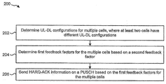
- Figure 2 is a flow diagram illustrating one configuration of a method for sending feedback information by a UE.
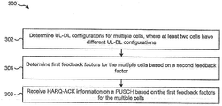
- Figure 3 is a flow diagram illustrating one configuration of a method for receiving feedback information by an eNB.
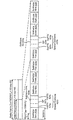
- Figure 4 is a diagram illustrating one example of a radio frame that may be used in accordance with the systems and methods disclosed herein.
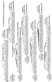
- Figure 5 is a diagram illustrating some UL-DL configurations in accordance with the systems and methods described herein.
- Figure 6 is a diagram illustrating an example of a primary cell (PCell) configuration and a secondary cell (SCell) configuration.
- PCell primary cell
- SCell secondary cell
- Figure 7 is a diagram illustrating another example of a PCell configuration and an SCell configuration.
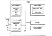
- Figure 8 illustrates various components that may be utilized in a UE.
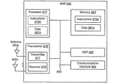
- Figure 9 illustrates various components that may be utilized in an eNB.
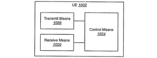
- Figure 10 is a block diagram illustrating one configuration of a UE in which systems and methods for sending feedback information may be implemented.
- Figure 11 is a block diagram illustrating one configuration of an eNB in which systems and methods for receiving feedback information may be implemented.
- the 3rd Generation Partnership Project also referred to as "3GPP," is a collaboration agreement that aims to define globally applicable technical specifications and technical reports for third and fourth generation wireless communication systems.
- the 3GPP may define specifications for next generation mobile networks, systems, and devices.
- 3GPP Long Term Evolution is the name given to a project to improve the Universal Mobile Telecommunications System (UMTS) mobile phone or device standard to cope with future requirements.
- UMTS has been modified to provide support and specification for the Evolved Universal Terrestrial Radio Access (E-UTRA) and Evolved Universal Terrestrial Radio Access Network (E-UTRAN).
- E-UTRA Evolved Universal Terrestrial Radio Access
- E-UTRAN Evolved Universal Terrestrial Radio Access Network
- At least some aspects of the systems and methods disclosed herein may be described in relation to the 3GPP LTE, LTE-Advanced (LTE-A) and other standards (e.g., 3GPP Releases 8, 9, 10 and/or 11). However, the scope of the present disclosure should not be limited in this regard. At least some aspects of the systems and methods disclosed herein may be utilized in other types of wireless communication systems.
- LTE LTE-Advanced
- other standards e.g., 3GPP Releases 8, 9, 10 and/or 11
- a wireless communication device may be an electronic device used to communicate voice and/or data to a base station, which in turn may communicate with a network of devices (e.g., public switched telephone network (PSTN), the Internet, etc.).
- a wireless communication device may alternatively be referred to as a mobile station, a UE, an access terminal, a subscriber station, a mobile terminal, a remote station, a user terminal, a terminal, a subscriber unit, a mobile device, etc.
- Examples of wireless communication devices include cellular phones, smart phones, personal digital assistants (PDAs), laptop computers, netbooks, e-readers, wireless modems, etc.
- PDAs personal digital assistants
- a wireless communication device is typically referred to as a UE.
- the terms "UE” and “wireless communication device” may be used interchangeably herein to mean the more general term "wireless communication device.”
- a base station In 3GPP specifications, a base station is typically referred to as a Node B, an eNB, a home enhanced or evolved Node B (HeNB) or some other similar terminology.
- base station As the scope of the disclosure should not be limited to 3GPP standards, the terms “base station,” “Node B,” “eNB,” and “HeNB” may be used interchangeably herein to mean the more general term “base station.”
- base station may be used to denote an access point.
- An access point may be an electronic device that provides access to a network (e.g., Local Area Network (LAN), the Internet, etc.) for wireless communication devices.
- the term “communication device” may be used to denote both a wireless communication device and/or a base station.
- a "cell” may be any communication channel that is specified by standardization or regulatory bodies to be used for International Mobile Telecommunications-Advanced (IMT-Advanced) and all of it or a subset of it may be adopted by 3GPP as licensed bands (e.g., frequency bands) to be used for communication between an eNB and a UE.
- Configured cells are those cells of which the UE is aware and is allowed by an eNB to transmit or receive information.
- Configured cell(s) may be serving cell(s). The UE may receive system information and perform the required measurements on all configured cells.
- Activated cells are those configured cells on which the UE is transmitting and receiving.
- activated cells are those cells for which the UE monitors the physical downlink control channel (PDCCH) and in the case of a downlink transmission, those cells for which the UE decodes a PDSCH.
- Deactivated cells are those configured cells that the UE is not monitoring the transmission PDCCH. It should be noted that a "cell” may be described in terms of differing dimensions or attributes. For example, a “cell” may have temporal, spatial (e.g., geographical), propagation and frequency characteristics.
- the systems and methods disclosed herein describe devices for sending and receiving feedback information. This may be done in the context of carrier aggregation. For example, PDSCH HARQ-ACK reporting and multiplexing on a PUSCH for carrier aggregation (e.g., inter-band or intra-band carrier aggregation) with different Time-Division Duplexing (TDD) UL-DL configurations is described.
- carrier aggregation e.g., inter-band or intra-band carrier aggregation
- TDD Time-Division Duplexing
- different TDD UL-DL configurations may be used for inter-band carrier aggregation.
- the cells or component carriers (CCs) in different bands may have different UL-DL configurations.
- Carrier aggregation refers to the concurrent utilization of more than one carrier.
- carrier aggregation may be used to increase the effective bandwidth available to a UE.
- One type of carrier aggregation is inter-band carrier aggregation.
- inter-band carrier aggregation multiple carriers from multiple bands may be aggregated. For example, a carrier in a first band may be aggregated with a carrier in a second band.
- the term "concurrent" and variations thereof may denote that at least two events may overlap each other in time, and may or may not mean that the at least two events begin and/or end at precisely the same time.
- the systems and methods disclosed herein may not be restricted to inter-band carrier aggregation and may also be applied to intra-band carrier aggregation.
- the term "configuration" may refer to an UL-DL configuration.
- An UL-DL configuration specifies whether each subframe within a radio frame is an UL subframe, a DL subframe or a special subframe. More detail regarding UL-DL configurations is given in connection with Table (1) below.
- a "PCell configuration” may refer to an UL-DL configuration that corresponds to a PCell.
- a PCell configuration is an UL-DL configuration applied by the eNB and UE for communications in the PCell.
- the PCell configuration may be signaled to a UE by an eNB in a SystemInformationBlockType1 (SIB-1).
- SIB-1 SystemInformationBlockType1
- the SIB-1 may be transmitted (by an eNB, for example) on a broadcast control channel as a logical channel.
- An "SCell configuration" may refer to an UL-DL configuration that corresponds to an SCell.
- an SCell configuration is an UL-DL configuration applied by the eNB and UE for communications in an SCell.
- An SCell configuration may be signaled to a UE with carrier aggregation by an eNB in dedicated Radio Resource Control (RRC) signaling.
- RRC Radio Resource Control
- the dedicated RRC signaling may be transmitted (by an eNB, for example) on a dedicated control channel as a logical channel.
- an eNB may send the SCell configuration in SIB-1 for UEs using the cell as a PCell.
- the eNB sends the same system information parameters between the SIB-1 for UEs using the cell as the PCell and the dedicated RRC signaling for UEs with carrier aggregation, though this is not strictly required.
- the parameters that are cell-specific parameters are signaled to a UE with carrier aggregation via dedicated RRC signaling and may be signaled to UEs using the cell as a PCell may be referred to as an SCell SIB-1 configuration or an SCell configuration.
- Carrier aggregation may assume that the same eNB scheduler manages communication resources for the PCell and SCell(s). Thus, the scheduler may know the actual configuration of each cell. The UEs may be informed (by an eNB, for example) of the actual UL-DL configuration of each aggregated cell, particularly if a cell has a different UL-DL configuration from the PCell.
- Time-Division Duplexing (TDD) Uplink-Downlink (UL-DL) configurations may be referred to as "UL-DL configurations" or a similar term herein for convenience.
- an UL-DL configuration corresponding to a PCell may be referred to as a "PCell configuration” and an UL-DL configuration corresponding to an SCell may be referred to as an "SCell configuration” for convenience herein.
- uplink may be abbreviated as “UL” and “downlink” may be abbreviated as "DL” for convenience herein.
- TDD UL-DL configurations 0-6 are given below in Table (1) (from Table 4.2-2 in 3GPP TS 36.211).
- UL-DL configurations with both 5 millisecond (ms) and 10 ms downlink-to-uplink switch-point periodicity may be supported.
- seven UL-DL configurations are specified in 3GPP specifications, as shown in Table (1) below.
- Table (1) "D” denotes a downlink subframe, "S” denotes a special subframe and "U” denotes an UL subframe.
- the UL-DL configurations illustrated in Table (1) may be utilized in accordance with the systems and methods disclosed herein.
- Enhanced carrier aggregation may include inter-band or intra-band carrier aggregation (CA) with different UL-DL configurations.
- CA intra-band carrier aggregation
- the systems and methods disclosed herein may enable inter-band CA with different UL-DL configurations, which may be supported in Rel-11.
- predetermined PDSCH HARQ-ACK reporting associations may be utilized in accordance with the systems and methods disclosed herein.
- TDD CA In LTE Releases 8 and 9, there is no aggregation of TDD cells.
- TDD CA In LTE Release 10, TDD CA only permits aggregation of cells with the same UL-DL configuration. Therefore, the same set of parameters is utilized to determine the HARQ-ACK bits of all cells. However, for releases beyond Release 10, for TDD CA with different UL-DL configurations, different sets of parameters may be utilized for different cells. Thus, new issues arise concerning multiplexing HARQ-ACK bits on different PUCCH formats as well as reporting procedures on the PUSCH.
- TDD carrier aggregation in Rel-10 only admits aggregation of cells with the same TDD configuration.
- the PDSCH HARQ-ACK reporting on the PUSCH uses a feedback factor to determine the number of subframes and HARQ-ACK bits to be reported for a cell in a PUSCH transmission adjusted based on a detected PDCCH with DCI format 0/4 (e.g., DCI format 0 or DCI format 4).
- the valid range of of a cell may be different from a cell with the same configuration.
- the procedure to determine may be different from Rel-10.
- multiple UL grants may be triggered from different subframes with different values, which may need to be specified in Rel-11 and beyond.
- the methods include determining uplink-downlink (UL-DL) configurations for multiple cells, where at least two of the multiple cells have different uplink-downlink (UL-DL) configurations.
- the methods also include determining first feedback factors for the multiple cells based on a second feedback factor.
- the methods further include sending and receiving Hybrid Automatic Repeat Request Acknowledgement/Negative Acknowledgement (HARQ-ACK) information on a Physical Uplink Shared Channel (PUSCH) based on the first feedback factors for the multiple cells.
- HARQ-ACK Hybrid Automatic Repeat Request Acknowledgement/Negative Acknowledgement
- Each of the first feedback factors may be where is the number of downlink subframes to feed back HARQ-ACK bits for a c-th serving cell.
- the second feedback factor may be which may be determined based on a Downlink Assignment Index (DAI) in DCI format 0/4. If UL-DL configuration 5 is configured for one of the multiple cells or is a reference configuration for one of the multiple cells, the first feedback factors may be determined based on a third feedback factor where denotes a maximum value of among all configured serving cells, where is the total number of received PDSCHs and PDCCH indicating a downlink semi-persistent scheduling (SPS) release on a c-th serving cell.
- SPS downlink semi-persistent scheduling
- the first feedback factors may be determined based on feedback parameters M c . For example, depending on the configurations, or etc.
- the range of may be determined in DCI format 0/4.
- the range of may be determined based on the maximum values of M c of all cells (more detail regarding M c is given below).
- M c maximum values of all cells
- UL-DL configuration 5 is configured for a cell or is used as the reference configuration of a cell, then for PDSCH HARQ-ACK reporting on the PUSCH in subframe 2 (e.g., an UL subframe for configuration 5 is subframe 2), the and HARQ-ACK bits of all cells may follow the rule for UL-DL configuration 5.
- the systems and methods disclosed herein may enable determining the feedback factor and HARQ-ACK bits used for other cells in adjusted PUSCH reporting for an UL grant issued by a cell with UL-DL configuration 0. Furthermore, the systems and methods disclosed herein may enable determining the values of in DCI format 0/4 with different UL grant timings. Additionally, the systems and methods disclosed herein may enable determining a selection scheme when multiple UL grants are triggered from multiple cells with multiple
- HARQ-ACK reporting on PUSCH in Rel-10 for more than one cell is described.
- UE procedures for determining Channel State Information (CSI) and HARQ-ACK reporting in Rel-10 are detailed in Section 10.1 of 3GPP TS 36.213, a portion of which is given below.
- the PDSCH HARQ-ACK may be reported on the PUSCH if simultaneous PUCCH and PUSCH is not configured.
- UCI shall be transmitted - on PUCCH using format 1/1a/1b/3 or 2/2a/2b if the UE is not transmitting PUSCH - on PUSCH of the serving cell given in section 7.2.1 if the UCI consists of aperiodic CSI or aperiodic CSI and HARQ-ACK - on primary cell PUSCH if the UCI consists of periodic CSI and/or HARQ-ACK and if the UE is transmitting on the primary cell PUSCH in subframe n unless the primary cell PUSCH transmission corresponds to a Random Access Response Grant or a retransmission of the same transport block as part of the contention based random access procedure, in which case UCI is not transmitted - on PUSCH of the secondary cell with smallest SCellIndex if the UCI consists of periodic CSI and/or HARQ-ACK and if the UE is not
- a value is determined by the Downlink Assignment Index (DAI) in DCI format 0/4 according to Table 7.3-Z in subframe n-k', where k' is defined in Table 7.3-Y.
- DAI Downlink Assignment Index
- N SPS which can be zero or one, as the number of PDSCH transmissions without a corresponding PDCCH within the subframe(s) n-k, where
- the HARQ-ACK feedback bits for the c-th serving cell configured by RRC are constructed as follows, where if transmission mode configured in the c-th serving cell supports one transport block or spatial HARQ-ACK bundling is applied and otherwise, where is the number of downlink subframes for which the UE needs to feedback HARQ-ACK bits for the c-th serving cell.
- M is the number of elements in the set K defined in Table 10.1.3.1-1 associated with subframe n and the set K does not include a special subframe of configurations 0 and 5 with normal downlink CP or of configurations 0 and 4 with extended downlink CP; otherwise
- the UE shall assume where M is the number of elements in the set K defined in Table 10.1.3.1-1 associated with subframe n and the set K does not include a special subframe of configurations 0 and 5 with normal downlink CP or of configurations 0 and 4 with extended downlink CP; otherwise The UE shall not transmit HARQ-ACK on PUSCH if the UE does not receive PDSCH or PDCCH indicating downlink SPS release in subframe(s) n-k, where
- the UE shall assume The UE shall not transmit HARQ-ACK on PUSCH if the UE does not receive PDSCH or PDCCH indicating downlink SPS release in subframe(s) n-k where
- the UE shall assume where denotes the maximum value of among all the configured serving cells, is the total number of received PDSCHs and PDCCH indicating downlink SPS release in subframe(s) n-k on the c-th serving cell, The UE shall not transmit HARQ-ACK on PUSCH if the UE does not receive PDSCH or PDCCH indicating downlink SPS release in subframe(s) n-k where
- the HARQ-ACK for a PDSCH transmission with a corresponding PDCCH or for a PDCCH indicating downlink SPS release in subframe n-k is associated with if transmission mode configured in the c-th serving cell supports one transport block or spatial HARQ-ACK bundling is applied, or associated with and otherwise, where DAI(k) is the value of DAI in DCI format 1A/1B/1D/1/2/2A/2B/2C detected in subframe n-k, are the HARQ-ACK feedback for codeword 0 and codeword 1, respectively.
- the HARQ-ACK associated with a PDSCH transmission without a corresponding PDCCH is mapped to
- the HARQ-ACK feedback bits without any detected PDSCH transmission or without detected PDCCH indicating downlink SPS release are set to NACK; - for TDD UL-DL configuration 0, the HARQ-ACK for a PDSCH transmission or for a PDCCH indicating downlink SPS release in subframe n-k is associated with if transmission mode configured in the c-th serving cell supports one transport block or spatial HARQ-ACK bundling is applied, or associated with otherwise, where are the HARQ-ACK feedback for codeword 0 and codeword 1, respectively.
- the HARQ-ACK feedback bits without any detected PDSCH transmission or without detected PDCCH indicating downlink SPS release are set to NACK.
- the HARQ-ACK feedback bits on PUSCH are constructed as follows.
- the UE shall not transmit HARQ-ACK on PUSCH if the UE does not receive PDSCH or PDCCH indicating downlink SPS release in subframe(s) n-k where
- a PUSCH transmission adjusted based on a detected PDCCH with DCI format 0/4 with is determined as if PUCCH format 3 is configured for transmission of HARQ-ACK, except that spatial HARQ-ACK bundling across multiple codewords within a DL subframe is performed for all serving cells configured with a downlink transmission mode that supports up to two transport blocks in case
- the UE shall not transmit HARQ-ACK on PUSCH if the UE does not receive PDSCH or PDCCH indicating downlink SPS release in subframe(s) n-k where
- the UE shall not transmit HARQ-ACK on PUSCH if the UE does not receive PDSCH or PDCCH indicating downlink SPS release in subframe(s) n-k where
- the UE shall not transmit HARQ-ACK on PUSCH if the UE does not receive PDSCH or PDCCH indicating downlink SPS release in subframe(s) n-k where
- one or more aspects of HARQ-ACK reporting with different TDD configurations may be given as follows.
- carrier aggregation enhancement support of different TDD uplink-downlink (UL-DL) configurations on different bands is considered.
- the carrier aggregation with different TDD configurations may be referred to as inter-band carrier aggregation.
- a PCell SIB1 configuration may be referred to as a PCell configuration
- an SCell SIB1 configuration may be referred to as an SCell configuration herein.
- Hybrid Automatic Repeat Request Acknowledgement/Negative Acknowledgement (“HARQ-ACK") of transmitted downlink communications may be transmitted on the Physical Uplink Control Channel (PUCCH) or the PUSCH.
- PUCCH Physical Uplink Control Channel
- HARQ-ACK Hybrid Automatic Repeat Request Acknowledgement/Negative Acknowledgement
- the systems and methods disclosed herein describe indicating and determining the number of HARQ-ACK bits of each cell when the UE is transmitting on PUSCH.
- the systems and methods disclosed herein also describe that the PUSCH transmission may be adjusted based on a detected PDCCH with DCI format 0/4 for the HARQ-ACK reporting.
- PDSCH HARQ-ACK reporting associations were given in accordance with the following.
- the PDSCH HARQ-ACK timing may be categorized into three cases (cases A, B and C), depending on whether the PCell configuration is a superset of the SCell configuration, a subset of the SCell configuration or neither.
- case A where the set of DL subframes indicated by the SCell configuration is a subset of the DL subframes indicated by the PCell configuration, the SCell may follow the PCell configuration.
- PDSCH HARQ-ACK reporting for case B and case C may be implemented as follows.
- case B at least in the context of self-scheduling and full duplex communications, where the set of DL subframes indicated by the PCell configuration is a subset of the DL subframes indicated by the SCell configuration, the SCell may follow the SCell configuration.
- the same rule may be applied in the context of half duplex communications.
- the cross-carrier scheduling case is left for further study.
- the SCell may follow a reference configuration as illustrated in Table (2) below.
- the reference configuration may be selected based on overlapping UL subframes in both the PCell and the SCell. In some implementations, the same rule may be applied in the context of half duplex communications.
- the cross-carrier scheduling case is left for further study.
- Table (2) below illustrates UL-DL configurations for PDSCH HARQ-ACK reporting.
- the columns illustrate PCell (TDD UL-DL) configurations 0-6, while the rows illustrate SCell (TDD UL-DL) configurations 0-6.
- the grid intersecting the PCell configurations and SCell configurations illustrates an UL-DL configuration with corresponding PDSCH HARQ-ACK timing that the SCell follows based on the case.
- "A” represents case A described above.
- SCell PDSCH HARQ-ACK timing follows the PCell configuration.
- B represents case B as described above.
- SCell PDSCH HARQ-ACK timing follows the SCell configuration.
- C represents case C as described above.
- SCell PDSCH HARQ-ACK timing follows a reference (TDD UL-DL) configuration indicated by the number that accompanies an instance of "C" in Table (2).
- the number in the grid in Table (2) is the reference configuration that SCell PDSCH HARQ-ACK timing follows in instances of case C.
- SCell PDSCH HARQ-ACK timing may follow configuration 4.
- a UE that supports aggregating more than one serving cell with frame structure type 2 is configured by higher layers to use either PUCCH format 1b with channel selection or PUCCH format 3 for transmission of HARQ-ACK when configured with more than one serving cell with frame structure type 2.
- a UE may be configured with PUCCH format 3 or PUCCH format 1b with channel selection for HARQ-ACK transmission.
- the HARQ-ACK transmission may proceed in accordance with Rel-10 specifications, except for the following.
- the set of DL subframes (denoted as K c ) on serving cell c associated with UL subframe n may include the DL subframes n-k, where and K is determined according to the timing reference configuration of serving cell c.
- K c is the number of elements in the set K c .
- a feedback factor if the timing reference configuration is UL-DL configuration 1, 2, 3, 4 or 6.
- the value of if the TDD UL-DL configuration (which is the timing reference configuration) is UL-DL configuration 5 is unaddressed in known approaches.
- Another case that is unaddressed in known approaches is if the timing reference configuration is UL-DL configuration 0, for HARQ-ACK transmission in an UL subframe n and on a PUSCH adjusted by an UL grant.
- a timing reference configuration may be the TDD UL-DL configuration which the PDSCH HARQ timing on serving cell c follows.
- the treatment of format 3 for a cross-carrier scheduling case may also be unaddressed in known approaches.
- the systems and methods disclosed herein may address open or unaddressed issues and may provide approaches for HARQ-ACK reporting on a PUSCH.
- all cells have the same TDD configuration and thus, the same UL grant timing.
- the UE may be the maximum number of the total number of PDCCH(s) with assigned PDSCH transmission(s) and the PDCCH indicating downlink SPS release among all configured cells. Additionally, the same can be applied for all configured cells.
- the systems and methods disclosed herein provide approaches to deal with the unaddressed cases (left over from RAN1 #69, for example). Furthermore, approaches are provided to determine for TDD CA with different TDD configurations. It should be noted that RAN1 #69 left some ambiguity in the use of and determination of HARQ-ACK bits.
- the UL grant timing of different cells may have different UL grant associations and different PDSCH HARQ-ACK association sets. If multiple UL grants are issued on multiple cells with different UL grant timings, the UE may receive multiple (sent from the eNB, for example) with the same or different values.
- the issues unaddressed in known approaches include the following: valid values represented by computation and interpretation of and managing multiple from multiple cells (particularly if they carry different values, for example).
- the systems and methods disclosed herein may be applied to at least a PDSCH self-scheduling case when different TDD configurations are used.
- the SCell follows PCell timing in an uplink subframe reporting
- the Rel-10 procedure may be reused for HARQ-ACK reporting on a PUSCH if the M c of the SCell is set the same as the M c of the PCell.
- the SCell follows a reference configuration as shown in Table (2), this becomes the same as the self-scheduling case and the systems and methods disclosed herein may be applied accordingly.
- the M (e.g., M c ) of the PCell may be the same as provided in Rel-10 specifications.
- the systems and methods disclosed herein provide two approaches to determine the M of the SCell.
- the M (e.g., M c ) of the SCell may be a reference parameter (e.g., M Ref ) based on a reference configuration. More specifically, M Ref may be the M of the reference configuration for which the PDSCH HARQ-ACK may be followed.
- the M (e.g., M c ) of the SCell is an effective parameter (e.g., M Eff ) based on the effective number of subframes in the reference configuration.
- M is the number of elements in the set K defined in Table (3) below (from Table 10.1.3.1-1 of 3GPP TS 36.213) associated with subframe n and the set K.
- a downlink association set index for TDD may be defined in Table (3) as K: ⁇ k 0 , k 1 , ..., k M-1 ⁇ , where M is the number of elements in the set K.
- the downlink association set depends on the UL-DL configuration, as given in Table (3) below.
- PDSCH HARQ-ACK timing may be based on one or more TDD UL-DL configurations in TDD CA with different configurations (as illustrated in Table (2), for example).
- a PDSCH HARQ-ACK association means the linkage between a PDSCH transmission and its HARQ-ACK feedback in an uplink subframe.
- the downlink association set index for TDD is defined in Table 10.1.3.1-1, which is illustrated as Table (3) below.
- Table (3) An entry in Table (3) defines a downlink association (e.g., a PDSCH HARQ-ACK association).
- the set K defines the PDSCH HARQ-ACK association set for a given uplink.
- the M c of a SCell may be defined as M Ref (e.g., the M of the reference configuration for which the PDSCH HARQ-ACK timing is followed).
- M Ref indicates the number of subframes with a PDSCH HARQ-ACK association for a reference configuration.
- M Ref M PCell where M PCell is the M of the PCell (e.g., the number of elements in the set K defined in Table (3) associated with subframe n and the set K according to the PCell configuration).
- M PCell indicates the number of subframes with a PDSCH HARQ-ACK association for the PCell configuration.
- M SCell M SCell
- M SCell the M of the SCell (e.g., the number of elements in the set K defined in Table (3) associated with subframe n and the set K according to the SCell configuration).
- M SCell indicates the number of subframes with a PDSCH HARQ-ACK association for the SCell configuration.
- M Ref M RefConf
- M RefConf a predetermined parameter
- M RefConf the M of the reference configuration (e.g., the number of elements in the set K defined in Table (3) associated with subframe n and the set K according to the reference UL-DL configuration in Table (2)).
- M RefConf indicates the number of subframes with a PDSCH HARQ-ACK association for the reference configuration.
- m may be defined as the number of conflicting subframes, where the PCell configuration includes a DL subframe (or special subframe, for example) and SCell configurations includes an UL subframe in the set K defined in Table (3) associated with subframe n and the set K according to the PCell configuration.
- m may be defined as the number of conflicting subframes (where the PCell configuration includes a DL subframe (or special subframe, for example) and the SCell configuration includes an UL subframe) in the set K defined in Table (3) associated with subframe n and the set K according to the reference configuration in Table (2).
- M Ref is the number of subframes with PDSCH HARQ-ACK associations for the reference configuration
- m is the number of the conflicting subframes that are downlink subframes and special subframes in the reference configuration and uplink subframes in the SCell configuration.
- the valid range that represents may be based on the maximum M c of all cells.
- the valid range that represents may be based on the maximum M c of all cells.
- W max the maximum M c of all cells
- W max max(M c ) of all cells. If a UL grant is issued from a cell with smaller M c , the value may be greater than the M c of the cell.
- M c may always be 1, thus Especially, in the association set of the reference configuration of an SCell, there may be one or more subframes in the SCell that are configured as UL. It may be better to remove these subframes in the adjusted case.
- the M c may be the effective M (e.g., M Eff ).
- configuration 5 is configured for a cell or configuration 5 is used as the reference configuration of a cell, for PDSCH HARQ-ACK reporting on PUSCH in subframe 2 (e.g., an UL subframe for configuration 5 is subframe 2), the and HARQ-ACK bits of all cells may follow the same rule as in configuration 5.
- the UE may assume that the feedback factor where another feedback factor denotes the maximum value of among all the configured serving cells, is the total number of received PDSCHs and PDCCH indicating downlink SPS release in subframe(s) n-k on the c-th serving cell and according to association set of the reference configuration in Table (2).
- M c may always be 1, thus Even for a cell with an UL-DL configuration ⁇ 1, 2, 3, 4, 6 ⁇ , if configuration 5 is used or is the reference configuration of any other cell, the may be determined in accordance with the second case instead of the first case. Particularly, in the association set of the reference configuration of an SCell, there may be one or more subframes in the SCell that are configured as UL. It may be better to remove these subframes in the adjusted case. Thus, the M c may be the effective M (e.g., M Eff ).
- Proposal II may enable determination of the in an UL grant.
- different cells may have different UL grant timings. It can be classified into two cases: case 1 and case 2.
- the eNB knows the maximum number of PDSCH allocated for each cell, and can signal the same used for all cells.
- W the maximum number of DL transmissions among the association sets of all cells according to Table (2) up to the given DL subframe that issues the UL grant.
- w the maximum number of DL subframes after the UL grant among the association sets of all cells.
- W' W.
- the UL grant in a cell with association timing that is greater than 4 ms does not count possible PDSCH transmissions in other cells after the given UL grant.
- the UE may add the detected number of PDSCH transmissions and SPS if any.
- the UE may not feedback HARQ-ACK for the PDSCH transmissions after the UL grant for the HARQ-ACK reporting on PUSCH.
- the UE may follow the of cell c to calculate For example, in Figure 6, suppose an UL grant is issued on the SCell in subframe 6 and no UL grant on the PCell in subframe 8. If a PDSCH is scheduled for the UE on the PCell in subframe 8, the UE does not include the HARQ-ACK of subframe 8 in the PUSCH of the SCell in subframe 2.
- Proposal III may enable an UL grant from a cell with configuration 0.
- For an UL grant is issued by a cell with configuration 0, there is no field in the DCI format 0/4 for configuration 0. Therefore, the procedures to determine the and HARQ-ACK bits used for other cells in adjusted PUSCH reporting on a cell with configuration 0 may need to be specified.
- the M c of the cell may be used, thus non-adjusted PUSCH reporting on a cell with configuration 0 may be used for HARQ-ACK bits for the cell and other cells.
- the UE sets the value for an UL grant for configuration 0 to 4 and applies proposal I procedure to calculate a feedback factor by using another feedback factor value as 4.
- the DCI of configuration 0 may be modified to include two bits for similar to other TDD UL-DL configurations.
- the UE may be configured based on RRC signaling implicitly or explicitly whether the UE needs to monitor the DCI format with field or without the field for configuration 0.
- an UL grant is triggered on a cell with configuration 0 for an UL subframe with HARQ-ACK association according to the reference configuration in Table (2), and no other UL grant is triggered from other cells that have been configured with other than TDD configuration 0.
- the HARQ-ACK may be reported on the PUSCH transmission of the cell with configuration 0.
- the may be used to determine the number of HARQ-ACK bits for cell c.
- the UE may miss the last PDCCH, thus the may be always the same or less than W c , e.g., The eNB may decode based on the number of subframe less than or equal to W c .
- an UL grant may be triggered on a cell with UL-DL configuration 0 for an UL subframe with HARQ-ACK association according to the reference configuration in Table (2), and one or more UL grants may be triggered from other cells that have been configured with an UL-DL configuration other than TDD configuration 0.
- the cell with configuration 0 has the lowest cell index.
- the HARQ-ACK may be reported on the PUSCH transmission of the cell with configuration 0.
- one or more may be signaled by UL grant of other cells.
- the feedback factor if configuration 5 is not used or not as reference configuration of any cells, for a cell with PUSCH transmission that may be adjusted based on the UL grant, The feedback factor if the timing reference configuration of cell c is ⁇ 1, 2, 3, 4, 6 ⁇ . If configuration 5 is used or is used as reference configuration of any cells, for a cell with PUSCH transmission that may be adjusted based on the UL grant, the feedback factor if configuration 5 is used or is used as reference configuration of any cells and the timing reference configuration of cell c is ⁇ 1, 2, 3, 4, 5, 6 ⁇ . For a cell with UL-DL configuration 0, M c may always be 1. Thus,
- Proposal IV enables handling of multiple UL grants from multiple cells with different timing. If multiple UL grants are issued from multiple cells with the same UL timing, the same may be signaled in all UL grants. Furthermore, the UE may use the given for all cells. However, if the UL grant timings of different cells are different, the UL grants may signal the same or different values as explained below.
- the of the UL grant of the cell with HARQ-ACK reporting in the PUSCH transmission may be used. This provides a simple solution where the UE follows the value on the PUSCH transmission with the lowest cell index number that signals an UL grant.
- the of the cell with the latest UL grant for the given subframe may be used. The latest includes the information of all previous UL grants associated with the given UL subframe. Thus, it may provide the most accurate estimation of PDSCH transmissions in all cells.
- the maximum of all cells may be used. This is a more conservative procedure. It trades off simplicity with potentially higher overhead for HARQ-ACK multiplexing on PUSCH.
- a cell without an UL grant may determine the based on one of the approaches above, and each cell that issues an UL grant follows its own value.
- an UL grant in an UL grant may be disabled for PUSCH transmission in an UL without PDSCH HARQ-ACK association. Furthermore, an UL grant may be triggered in subframe 9 on an SCell for PUSCH transmission on an SCell in subframe 3 of the next radio frame, but no HARQ-ACK may be reported in subframe 3. Thus, the in the UL grant may be meaningless. Thus, in an UL grant that is scheduled for PUSCH transmission in an UL subframe without a HARQ-ACK association according to the reference configuration in Table (2), the may be disabled or ignored by the UE.
- Figure 1 is a block diagram illustrating one configuration of one or more eNBs 160 and one or more UEs 102 in which systems and methods for sending and receiving feedback information may be implemented.
- the one or more UEs 102 communicate with one or more eNBs 160 using one or more antennas 122a-n.
- a UE 102 transmits electromagnetic signals to the eNB 160 and receives electromagnetic signals from the eNB 160 using the one or more antennas 122a-n.
- the eNB 160 communicates with the UE 102 using one or more antennas 180a-n.
- the UE 102 and the eNB 160 may use one or more channels 119, 121 to communicate with each other.
- a UE 102 may transmit information or data to the eNB 160 using one or more uplink channels 121.
- uplink channels 121 include a PUCCH and a PUSCH, etc.
- the one or more eNBs 160 may also transmit information or data to the one or more UEs 102 using one or more downlink channels 119, for instance.
- Examples of downlink channels 119 include a PDCCH, a PDSCH, etc. Other kinds of channels may be used.
- Each of the one or more UEs 102 may include one or more transceivers 118, one or more demodulators 114, one or more decoders 108, one or more encoders 150, one or more modulators 154, a data buffer 104 and a UE operations module 124.
- one or more reception and/or transmission paths may be implemented in the UE 102.
- only a single transceiver 118, decoder 108, demodulator 114, encoder 150 and modulator 154 are illustrated in the UE 102, though multiple parallel elements (e.g., transceivers 118, decoders 108, demodulators 114, encoders 150 and modulators 154) may be implemented.
- the transceiver 118 may include one or more receivers 120 and one or more transmitters 158.
- the one or more receivers 120 may receive signals from the eNB 160 using one or more antennas 122a-n.
- the receiver 120 may receive and downconvert signals to produce one or more received signals 116.
- the one or more received signals 116 may be provided to a demodulator 114.
- the one or more transmitters 158 may transmit signals to the eNB 160 using one or more antennas 122a-n.
- the one or more transmitters 158 may upconvert and transmit one or more modulated signals 156.
- the demodulator 114 may demodulate the one or more received signals 116 to produce one or more demodulated signals 112.
- the one or more demodulated signals 112 may be provided to the decoder 108.
- the UE 102 may use the decoder 108 to decode signals.
- the decoder 108 may produce one or more decoded signals 106, 110.
- a first UE-decoded signal 106 may comprise received payload data, which may be stored in a data buffer 104.
- a second UE-decoded signal 110 may comprise overhead data and/or control data.
- the second UE-decoded signal 110 may provide data that may be used by the UE operations module 124 to perform one or more operations.
- module may mean that a particular element or component may be implemented in hardware, software or a combination of hardware and software. However, it should be noted that any element denoted as a “module” herein may alternatively be implemented in hardware.
- the UE operations module 124 may be implemented in hardware, software or a combination of both.
- the UE operations module 124 may enable the UE 102 to communicate with the one or more eNBs 160.
- the UE operations module 124 may include one or more of UL-DL configurations 128, a UE UL-DL configuration determination module 130, a HARQ-ACK generation module 132, a UE feedback factor determination module 134, a UE feedback parameter determination module 126 and a format application module 184.
- the UL-DL configurations 128 may specify a set of UL-DL configurations that may be used for communication between the UE 102 and the eNB 160. Examples of UL-DL configurations include the UL-DL configurations 0-6 illustrated in Table (1) above.
- the UL-DL configurations 128 may specify UL, DL and special subframes for communication with the eNB(s) 160.
- the UL-DL configurations 128 may indicate DL subframes for the UE 102 to receive information from the eNB 160 and may indicate UL subframes for the UE 102 to transmit information to the eNB 160.
- the UE 102 and the eNB 160 may apply the same UL-DL configuration 128 on the same cell. However, different UL-DL configurations 128 may be applied on different cells (e.g., PCell and SCell(s)).
- the UL-DL configurations 128 may also indicate PDSCH HARQ-ACK associations (as illustrated in Table (3) above, for example).
- a PDSCH HARQ-ACK association may specify a particular (PDSCH HARQ-ACK) timing for sending HARQ-ACK information corresponding to a PDSCH.
- the HARQ-ACK generation module 132 may generate HARQ-ACK information corresponding to a PDSCH based on whether a signal (e.g., data) in the PDSCH was correctly received or not.
- a PDSCH HARQ-ACK association may specify a reporting subframe in which the UE 102 reports (e.g., transmits) the HARQ-ACK information corresponding to the PDSCH. The reporting subframe may be determined based on the subframe that includes the PDSCH.
- the UE UL-DL configuration determination module 130 may determine which of the UL-DL configuration(s) 128 for the UE 102 to apply for one or more cells. For example, the UE 102 may receive one or more RRC configuration (e.g., SIB-1 broadcasted information or dedicated signaling) indicating UL-DL configuration(s) 128 for a PCell and for one or more SCells. For instance, a PCell and an SCell may be utilized in carrier aggregation. The UE UL-DL configuration determination module 130 may determine which UL-DL configuration 128 is assigned to the PCell and which UL-DL configuration 128 is assigned to the SCell. The UL-DL configurations 128 for the PCell and SCell(s) may be the same or different.
- RRC configuration e.g., SIB-1 broadcasted information or dedicated signaling
- the UE feedback factor determination module 134 may determine feedback factors For example, the UE feedback factor determination module 134 may determine feedback factors where is the number of downlink subframes to feed back HARQ-ACK bits for a c-th serving cell. Additionally or alternatively, the UE feedback factor determination module 134 may determine a feedback factor where denotes a maximum value of among all configured serving cells, where is the total number of received PDSCHs and PDCCH indicating a downlink semi-persistent scheduling (SPS) release on a c-th serving cell.
- SPS downlink semi-persistent scheduling
- the feedback factors may indicate (e.g., be utilized to determine) the number of subframes and HARQ-ACK bits to be reported for one or more cells in a PUSCH transmission adjusted based on a detected PDCCH with DCI format 0/4, for example.
- the UE 102 receives one or more feedback factors in one or more uplink (UL) grants.
- the UE feedback factor determination module 134 may determine one or more feedback factors in accordance with one or more of the proposals, approaches, cases, procedures, etc., described above.
- a UE reporting subframe determination module may determine a reporting subframe for sending HARQ-ACK information.
- the UE reporting subframe determination module may determine a HARQ-ACK reporting subframe in which the UE 102 sends SCell HARQ-ACK information (e.g., PDSCH HARQ-ACK information corresponding to an SCell).
- SCell HARQ-ACK information e.g., PDSCH HARQ-ACK information corresponding to an SCell.
- the UE reporting subframe determination module may determine a reporting subframe for sending SCell HARQ-ACK information on the PCell according to the timing reference described above in Table (3).
- Table (3) above (e.g., the PDSCH HARQ-ACK association table) gives the location of a corresponding PDSCH by the index set K: ⁇ k 0 , k 1 , ..., k M-1 ⁇ for a subframe (e.g., UL subframe) number n, where the HARQ-ACK of a PDSCH in subframe n-k (e.g., n-k 1 ) is reported in UL subframe n.
- the UE 102 may send the SCell HARQ-ACK information in the determined HARQ-ACK reporting subframe.
- the UE feedback parameter determination module 126 may determine one or more feedback parameters corresponding to one or more cells (e.g., PCell, SCell(s)). For example, the UE feedback parameter determination module 126 may determine a feedback parameter M c for one or more cells c. This determination may be accomplished as described above, for example. In some implementations, the determination may be based on one or more of a PCell configuration, an SCell configuration, a reference configuration, the number of conflicting subframes and a feedback parameter determination scheme.
- the format application module 184 may apply a particular format to the HARQ-ACK information in certain cases.
- the format application module 184 may format HARQ-ACK information in accordance with the number of subframes and HARQ-ACK bits indicated by the one or more feedback factors.
- the format application module 184 may apply one or more of the proposals, approaches, procedures, ways and techniques described above.
- the UE 102 may receive a selection scheme indicator from the eNB 160.
- the selection scheme indicator may specify one or more of the proposals, approaches, procedures, ways and techniques described above.
- the format application module 184 may apply a particular format in accordance with the specified one or more of the proposals, approaches, procedures, ways and techniques described above. This may allow the UE 102 and the eNB 160 to utilize the same selection scheme in implementations where multiple selection schemes may be applied.
- the UE operations module 124 may provide information 148 to the one or more receivers 120. For example, the UE operations module 124 may inform the receiver(s) 120 when or when not to receive transmissions based on the UL-DL configurations 128.
- the UE operations module 124 may provide information 138 to the demodulator 114. For example, the UE operations module 124 may inform the demodulator 114 of a modulation pattern anticipated for transmissions from the eNB 160.
- the UE operations module 124 may provide information 136 to the decoder 108. For example, the UE operations module 124 may inform the decoder 108 of an anticipated encoding for transmissions from the eNB 160.
- the UE operations module 124 may provide information 142 to the encoder 150.
- the information 142 may include data to be encoded and/or instructions for encoding.
- the UE operations module 124 may instruct the encoder 150 to encode transmission data 146 and/or other information 142.
- the other information 142 may include PDSCH HARQ-ACK information.
- the encoder 150 may encode transmission data 146 and/or other information 142 provided by the UE operations module 124. For example, encoding the data 146 and/or other information 142 may involve error detection and/or correction coding, mapping data to space, time and/or frequency resources for transmission, multiplexing, etc.
- the encoder 150 may provide encoded data 152 to the modulator 154.
- the UE operations module 124 may provide information 144 to the modulator 154.
- the UE operations module 124 may inform the modulator 154 of a modulation type (e.g., constellation mapping) to be used for transmissions to the eNB 160.
- the modulator 154 may modulate the encoded data 152 to provide one or more modulated signals 156 to the one or more transmitters 158.
- the UE operations module 124 may provide information 140 to the one or more transmitters 158.
- This information 140 may include instructions for the one or more transmitters 158.
- the UE operations module 124 may instruct the one or more transmitters 158 when to transmit a signal to the eNB 160. In some configurations, this may be based on a UL-DL configuration 128.
- the one or more transmitters 158 may transmit during an UL subframe.
- the one or more transmitters 158 may upconvert and transmit the modulated signal(s) 156 to one or more eNBs 160.
- the eNB 160 may include one or more transceivers 176, one or more demodulators 172, one or more decoders 166, one or more encoders 109, one or more modulators 113, a data buffer 162 and an eNB operations module 182.
- one or more reception and/or transmission paths may be implemented in an eNB 160.
- only a single transceiver 176, decoder 166, demodulator 172, encoder 109 and modulator 113 are illustrated in the eNB 160, though multiple parallel elements (e.g., transceivers 176, decoders 166, demodulators 172, encoders 109 and modulators 113) may be implemented.
- the transceiver 176 may include one or more receivers 178 and one or more transmitters 117.
- the one or more receivers 178 may receive signals from the UE 102 using one or more antennas 180a-n.
- the receiver 178 may receive and downconvert signals to produce one or more received signals 174.
- the one or more received signals 174 may be provided to a demodulator 172.
- the one or more transmitters 117 may transmit signals to the UE 102 using one or more antennas 180a-n.
- the one or more transmitters 117 may upconvert and transmit one or more modulated signals 115.
- the demodulator 172 may demodulate the one or more received signals 174 to produce one or more demodulated signals 170.
- the one or more demodulated signals 170 may be provided to the decoder 166.
- the eNB 160 may use the decoder 166 to decode signals.
- the decoder 166 may produce one or more decoded signals 164, 168.
- a first eNB-decoded signal 164 may comprise received payload data, which may be stored in a data buffer 162.
- a second eNB-decoded signal 168 may comprise overhead data and/or control data.
- the second eNB-decoded signal 168 may provide data (e.g., PDSCH HARQ-ACK information) that may be used by the eNB operations module 182 to perform one or more operations.
- the eNB operations module 182 may enable the eNB 160 to communicate with the one or more UEs 102.
- the eNB operations module 182 may include one or more of UL-DL configurations 194, an eNB feedback factor determination module 198, an eNB UL-DL configuration determination module 196, an eNB feedback parameter determination module 151 and an interpreter 107.
- the eNB operations module 182 may also include a scheme signaling module 153.
- the UL-DL configurations 194 may specify a set of UL-DL configurations that may be used for communication between the eNB 160 and the UE(s) 102. Examples of UL-DL configurations 194 include the UL-DL configurations 0-6 illustrated in Table (1) above.
- the UL-DL configurations 194 may specify UL and DL subframes for communication with the UE(s) 102. For example, the UL-DL configurations 194 may indicate DL subframes for the eNB 160 to send information to the UE(s) 102 and may indicate UL subframes for the eNB 160 to receive information from the UE(s) 102.
- the UE 102 and the eNB 160 may apply the same UL-DL configuration 194 on the same cell.
- different UL-DL configurations 194 may be applied on different cells (e.g., PCell and SCell(s)).
- the UL-DL configurations 194 may also indicate PDSCH HARQ-ACK associations (as illustrated in Table (3), for example).
- a PDSCH HARQ-ACK association may specify a particular (PDSCH HARQ-ACK) timing for receiving HARQ-ACK information corresponding to a PDSCH.
- a PDSCH HARQ-ACK association may specify a reporting subframe in which the UE 102 reports (e.g., transmits) the HARQ-ACK information corresponding to the PDSCH to the eNB 160. The reporting subframe may be determined based on the subframe that includes the PDSCH sent by the eNB 160.
- the eNB UL-DL configuration determination module 196 may determine which of the UL-DL configuration(s) 194 for the UE 102 to apply for one or more cells. For example, the eNB 160 may send one or more RRC configuration (e.g., SIB-1 broadcasted information or dedicated signaling) indicating UL-DL configuration(s) 194 for a PCell and for one or more SCells. For instance, a PCell and an SCell may be utilized in carrier aggregation. The eNB UL-DL configuration determination module 196 may assign UL-DL configuration(s) 194 to the PCell and to the SCell. The eNB 160 may signal one or more of these assignments to a UE 102. The UL-DL configurations 194 for the PCell and SCell(s) may be the same or different.
- RRC configuration e.g., SIB-1 broadcasted information or dedicated signaling
- the eNB feedback factor determination module 198 may determine feedback factors For example, the eNB feedback factor determination module 198 may determine feedback factors where is the number of downlink subframes to feed back HARQ-ACK bits for a c-th serving cell. Additionally or alternatively, the eNB feedback factor determination module 198 may determine a feedback factor , where denotes a maximum value of among all configured serving cells, where is the total number of received PDSCHs and PDCCH indicating a downlink semi-persistent scheduling (SPS) release on a c-th serving cell.
- SPS downlink semi-persistent scheduling
- the feedback factors may indicate (e.g., be utilized to determine) the number of subframes and HARQ-ACK bits to be reported for one or more cells in a PUSCH transmission adjusted based on a detected PDCCH with DCI format 0/4, for example.
- the eNB 160 sends one or more feedback factors in one or more uplink (UL) grants.
- the eNB feedback factor determination module 198 may determine one or more feedback factors in accordance with one or more of the proposals, approaches, cases, procedures, etc., described above.
- An eNB reporting subframe determination module may determine a reporting subframe for receiving HARQ-ACK information.
- the eNB reporting subframe determination module may determine a HARQ-ACK reporting subframe in which the eNB 160 receives SCell PDSCH HARQ-ACK information (e.g., PDSCH HARQ-ACK information corresponding to an SCell) from a UE 102.
- SCell PDSCH HARQ-ACK information e.g., PDSCH HARQ-ACK information corresponding to an SCell
- the eNB reporting subframe determination module may determine a reporting subframe for receiving SCell HARQ-ACK information on the PCell according to the timing reference described above in Table (3).
- Table (3) above (e.g., the PDSCH HARQ-ACK association table) gives the location of a corresponding PDSCH by the index set K: ⁇ k 0 , k 1 , ..., k M-1 ⁇ , for a subframe (e.g., UL subframe) number n, where the HARQ-ACK of a PDSCH in subframe n-k (e.g., n-k 1 ) is reported in UL subframe n.
- the eNB 160 may receive the SCell HARQ-ACK information in the determined HARQ-ACK reporting subframe.
- the eNB feedback parameter determination module 151 may determine one or more feedback parameters corresponding to one or more cells (e.g., PCell, SCell(s)). For example, the eNB feedback parameter determination module 151 may determine a feedback parameter M c for one or more cells c. This determination may be accomplished as described above (and in connection with Figure 3, for instance), for example. In some implementations, the determination may be based on one or more of a PCell configuration, an SCell configuration, a reference configuration, the number of conflicting subframes and a feedback parameter determination scheme.
- the optional scheme signaling module 153 may generate one or more of a feedback parameter determination scheme indicator and a selection scheme indicator.
- one of multiple feedback parameter determination schemes may be utilized.
- the eNB 160 may signal which scheme is utilized.
- only one feedback parameter determination scheme may be utilized by the eNB 160 and UE 102. In these implementations, the eNB 160 may not signal a feedback parameter determination scheme.
- one of multiple selection schemes may be utilized.
- the eNB 160 may signal which scheme is utilized.
- the eNB 160 may send a selection scheme indicator that indicates one or more of the proposals, approaches, cases, procedures, etc., described above (for application by the UE 102 in determining feedback factor(s), for example).
- only one selection scheme may be utilized by the eNB 160 and UE 102.
- the eNB 160 may not signal a selection scheme.
- the interpreter 107 may interpret formats of the HARQ-ACK information in certain cases. For example, the interpreter 107 may interpret HARQ-ACK information based on one or more feedback factors. For instance, the feedback factors may be used to determine the number of subframes and HARQ-ACK bits for receipt from the UE 102. For instance, the interpreter 107 may interpret received HARQ-ACK information in accordance with one or more of the proposals, approaches, procedures, techniques and ways described above.
- the eNB operations module 182 may provide information 190 to the one or more receivers 178. For example, the eNB operations module 182 may inform the receiver(s) 178 when or when not to receive transmissions based on a UL-DL configuration 194 for a given cell.
- the eNB operations module 182 may provide information 188 to the demodulator 172. For example, the eNB operations module 182 may inform the demodulator 172 of a modulation pattern anticipated for transmissions from the UE(s) 102.
- the eNB operations module 182 may provide information 186 to the decoder 166. For example, the eNB operations module 182 may inform the decoder 166 of an anticipated encoding for transmissions from the UE(s) 102.
- the eNB operations module 182 may provide information 101 to the encoder 109.
- the information 101 may include data to be encoded and/or instructions for encoding.
- the eNB operations module 182 may instruct the encoder 109 to encode transmission data 105 and/or other information 101.
- the other information 101 may include one or more of RRC configuration (e.g., SIB-1 broadcasted information or dedicated signaling) (e.g., PCell configuration indicator, SCell configuration indicator), a channel scheme determination indicator and a feedback parameter determination scheme indicator, for example.
- the encoder 109 may encode transmission data 105 and/or other information 101 provided by the eNB operations module 182. For example, encoding the data 105 and/or other information 101 may involve error detection and/or correction coding, mapping data to space, time and/or frequency resources for transmission, multiplexing, etc.
- the encoder 109 may provide encoded data 111 to the modulator 113.
- the transmission data 105 may include network data to be relayed to the UE 102.
- the eNB operations module 182 may provide information 103 to the modulator 113.
- This information 103 may include instructions for the modulator 113.
- the eNB operations module 182 may inform the modulator 113 of a modulation type (e.g., constellation mapping) to be used for transmissions to the UE(s) 102.
- the modulator 113 may modulate the encoded data 111 to provide one or more modulated signals 115 to the one or more transmitters 117.
- the eNB operations module 182 may provide information 192 to the one or more transmitters 117.
- This information 192 may include instructions for the one or more transmitters 117.
- the eNB operations module 182 may instruct the one or more transmitters 117 when to (or when not to) transmit a signal to the UE(s) 102. In some implementations, this may be based on an UL-DL configuration 194.
- the one or more transmitters 117 may upconvert and transmit the modulated signal(s) 115 to one or more UEs 102.
- a DL subframe may be transmitted from the eNB 160 to one or more UEs 102 and that an UL subframe may be transmitted from one or more UEs 102 to the eNB 160. Furthermore, both the eNB 160 and the one or more UEs 102 may transmit data in a standard special subframe.
- one or more of the elements or parts thereof included in the eNB(s) 160 and UE(s) 102 may be implemented in hardware.
- one or more of these elements or parts thereof may be implemented as a chip, circuitry or hardware components, etc.
- one or more of the functions or methods described herein may be implemented in and/or performed using hardware.
- one or more of the methods described herein may be implemented in and/or realized using a chipset, an application-specific integrated circuit (ASIC), a large-scale integrated circuit (LSI) or integrated circuit, etc.
- ASIC application-specific integrated circuit
- LSI large-scale integrated circuit
- FIG. 2 is a flow diagram illustrating one configuration of a method 200 for sending feedback information by a UE 102.
- a UE 102 may determine 202 UL-DL configurations for multiple cells, where at least two cells have different UL-DL configurations.
- the UE 102 may receive one or more RRC configuration (e.g., SIB-1 broadcasted information or dedicated signaling) indicating UL-DL configuration(s) 128 for a PCell and for one or more SCells.
- a PCell and an SCell may be utilized in carrier aggregation.
- the UE UL-DL configuration determination module 130 may determine which UL-DL configuration 128 is assigned to the PCell and which UL-DL configuration 128 is assigned to the SCell.
- the UL-DL configurations 128 for the PCell and SCell(s) may be the same or different.
- the UE 102 may determine 204 first feedback factors for the multiple cells based on a second feedback factor Determining 204 the first feedback factors may be further based on a third feedback factor if UL-DL configuration 5 is configured for at least one of the multiple cells or is a reference configuration for at least one of the multiple cells. For example, the UE 102 may determine 204 first feedback factors in accordance with one or more of the proposals, cases, approaches, procedures, etc., described above.
- the UE 102 may send 206 HARQ-ACK information on a PUSCH based on the first feedback factors for the multiple cells.
- the first feedback factors may be utilized to determine the number of subframes and HARQ-ACK bits for transmission to an eNB 160.
- FIG. 3 is a flow diagram illustrating one configuration of a method 300 for receiving feedback information by a eNB 106.
- a eNB 106 may determine 302 UL-DL configurations for multiple cells, where at least two cells have different UL-DL configurations.
- the eNB 106 may send one or more RRC configuration (e.g., SIB-1 broadcasted information or dedicated signaling) indicating UL-DL configuration(s) 128 for a PCell and for one or more SCells.
- RRC configuration e.g., SIB-1 broadcasted information or dedicated signaling
- a PCell and an SCell may be utilized in carrier aggregation.
- the UE UL-DL configuration determination module 130 may determine which UL-DL configuration 128 is assigned to the PCell and which UL-DL configuration 128 is assigned to the SCell.
- the UL-DL configurations 128 for the PCell and SCell(s) may be the same or different.
- the eNB 106 may determine 304 first feedback factors for the multiple cells based on a second feedback factor Determining 304 the first feedback factors may be further based on a third feedback factor if UL-DL configuration 5 is configured for at least one of the multiple cells or is a reference configuration for at least one of the multiple cells. For example, the eNB 106 may determine 304 first feedback factors in accordance with one or more of the proposals, cases, approaches, procedures, etc., described above.
- the eNB 106 may receive 306 HARQ-ACK information on a PUSCH based on the first feedback factors for the multiple cells.
- the first feedback factors may be utilized to determine the number of subframes and HARQ-ACK bits for reception from a UE 102.
- FIG. 4 is a diagram illustrating one example of a radio frame 435 that may be used in accordance with the systems and methods disclosed herein.
- This radio frame 435 structure may be applicable in TDD approaches.
- Each radio frame 435 may have a length of where T f is a radio frame 435 duration and T s is a time unit equal to
- the radio frame 435 may include two half-frames 433, each having a length of
- Each half-frame 433 may include five subframes 423a-e, 423f-j each having a length of
- D indicates that the subframe is reserved for downlink transmissions
- U indicates that the subframe is reserved for uplink transmissions
- S indicates a special subframe with three fields: a downlink pilot time slot (DwPTS), a guard period (GP) and an uplink pilot time slot (UpPTS).
- DwPTS downlink pilot time slot
- GP guard period
- UpPTS uplink pilot time slot
- the length of DwPTS and UpPTS is given in Table (4) (from Table 4.2-1 of 3GPP TS 36.211) subject to the total length of DwPTS, GP and UpPTS being equal to Table (4) illustrates several configurations of (standard) special subframes.
- Each subframe i is defined as two slots, 2i and 2i+1 of length in each subframe.
- cyclic prefix is abbreviated as “CP” and “configuration” is abbreviated as "Config" for convenience.
- UL-DL configurations with both 5 ms and 10 ms downlink-to-uplink switch-point periodicity are supported.
- the special subframe exists in both half-frames.
- the special subframe exists in the first half-frame only.
- Subframes 0 and 5 and DwPTS may be reserved for downlink transmission.
- UpPTS and the subframe immediately following the special subframe may be reserved for uplink transmission.
- some types of subframes 423 that may be used include a downlink subframe, an uplink subframe and a special subframe 431.
- a downlink subframe an uplink subframe
- a special subframe 431 In the example illustrated in Figure 4, which has a 5 ms periodicity, two standard special subframes 431a-b are included in the radio frame 435.
- the first special subframe 431a includes a downlink pilot time slot (DwPTS) 425a, a guard period (GP) 427a and an uplink pilot time slot (UpPTS) 429a.
- the first standard special subframe 431a is included in subframe one 423b.
- the second standard special subframe 431b includes a downlink pilot time slot (DwPTS) 425b, a guard period (GP) 427b and an uplink pilot time slot (UpPTS) 429b.
- the second standard special subframe 431b is included in subframe six 423g.
- the length of the DwPTS 425a-b and UpPTS 429a-b may be given by Table 4.2-1 of 3GPP TS 36.211 (illustrated in Table (5) above) subject to the total length of each set of DwPTS 425, GP 427 and UpPTS 429 being equal to
- Each subframe i 423a-j (where i denotes a subframe ranging from subframe zero 423a (e.g., 0) to subframe nine 423j (e.g., 9) in this example) is defined as two slots, 2i and 2i+1 of length in each subframe 423.
- subframe zero (e.g., 0) 423a may include two slots, including a first slot.
- FIG. 4 illustrates one example of a radio frame 435 with 5 ms switch-point periodicity.
- each half-frame 433 includes a standard special subframe 431a-b.
- a special subframe may exist in the first half-frame 433 only.
- Subframe zero (e.g., 0) 423a and subframe five (e.g., 5) 423f and DwPTS 425a-b may be reserved for downlink transmission.
- the UpPTS 429a-b and the subframe(s) immediately following the special subframe(s) 431a-b (e.g., subframe two 423c and subframe seven 423h) may be reserved for uplink transmission.
- special subframes 431 may be considered DL subframes in order to determine the number of conflicting subframes.
- Figure 5 is a diagram illustrating some UL-DL configurations 537a-g in accordance with the systems and methods described herein.
- Figure 5 illustrates UL-DL configuration zero 537a (e.g., "UL-DL configuration 0") with subframes 523a and subframe numbers 539a, UL-DL configuration one 537b (e.g., "UL-DL configuration 1") with subframes 523b and subframe numbers 539b, UL-DL configuration two 537c (e.g., "UL-DL configuration 2") with subframes 523c and subframe numbers 539c and UL-DL configuration three 537d (e.g., "UL-DL configuration 3") with subframes 523d and subframe numbers 539d.
- UL-DL configuration zero 537a e.g., "UL-DL configuration 0
- UL-DL configuration one 537b e.g., "UL-DL configuration 1"
- UL-DL configuration two 537c e.g., "UL
- Figure 5 also illustrates UL-DL configuration four 537e (e.g., "UL-DL configuration 4") with subframes 523e and subframe numbers 539e, UL-DL configuration five 537f (e.g., "UL-DL configuration 5") with subframes 523f and subframe numbers 539f and UL-DL configuration six 537g (e.g., "UL-DL configuration 6") with subframes 523g and subframe numbers 539g.
- UL-DL configuration four 537e e.g., "UL-DL configuration 4
- UL-DL configuration five 537f e.g., "UL-DL configuration 5
- subframes 523f and subframe numbers 539f e.g., "UL-DL configuration 6”
- Figure 5 further illustrates PDSCH HARQ-ACK associations 541 (e.g., PDSCH HARQ-ACK feedback on PUCCH or PUSCH associations).
- the PDSCH HARQ-ACK associations 541 may indicate HARQ-ACK reporting subframes corresponding to subframes for PDSCH transmissions (e.g., subframes in which PDSCH transmissions may be sent and/or received). It should be noted that some of the radio frames illustrated in Figure 5 have been truncated for convenience.
- the systems and methods disclosed herein may be applied to one or more of the UL-DL configurations 537a-g illustrated in Figure 5.
- one or more PDSCH HARQ-ACK associations 541 corresponding to one of the UL-DL configurations 537a-g illustrated in Figure 5 may be applied to communications between a UE 102 and eNB 160.
- an UL-DL configuration 537 may be determined (e.g., assigned to, applied to) a PCell.
- PDSCH HARQ-ACK associations 541 may specify PDSCH HARQ-ACK timing (e.g., a HARQ-ACK reporting subframe) for HARQ-ACK feedback transmissions corresponding to the PCell.
- the PDSCH HARQ-ACK associations 541 corresponding to a reference UL-DL configuration in accordance with the feedback parameters may be utilized.
- the PDSCH HARQ-ACK information may be formatted and reported in an uplink subframe based on Format 1b with channel selection as described above.
- Figure 6 is a diagram illustrating an example of a PCell configuration and an SCell configuration.
- Figure 6 illustrates PCell configuration 2 (e.g., "two") 637a with subframes 623a and subframe numbers 639a in addition to SCell configuration 1 (e.g., "one") 637b with subframes 623b and subframe numbers 639b.
- SCell configuration 1 e.g., "one”
- ACK/NACK feedback for downlink transmission associations 641 and downlink schedule for PUSCH transmission associations 643 are illustrated.
- Figure 6 is an example of different UL grant timing.
- Figure 6 shows an example with a PCell configured with UL-DL configuration 2 and an SCell with UL-DL configuration 1.
- the PDSCH HARQ-ACK of the SCell follows the PCell timing in this case.
- the SCell follows its own UL grant (e.g., the PUSCH scheduling timing).
- Figure 7 is a diagram illustrating another example of a PCell configuration and an SCell configuration.
- Figure 7 illustrates PCell configuration 1 (e.g., "one") 737a with subframes 723a and subframe numbers 739a in addition to SCell configuration 2 (e.g., "two") 737b with subframes 723b and subframe numbers 739b.
- SCell configuration 2 e.g., "two”
- ACK/NACK feedback for downlink transmission associations 741 and downlink schedule for PUSCH transmission associations 743 are illustrated.
- the example in Figure 7 is another example of different UL grant timing.
- the same issue exists if the PCell has an UL grant in subframe 6 and no UL grant from SCell.
- the PCell is configured with configuration 1 and the SCell with configuration 2.
- the PCell and SCell follow their own PDSCH and PUSCH timing, and are different from each other.
- Figure 8 illustrates various components that may be utilized in a UE 802.
- the UE 802 described in connection with Figure 8 may be implemented in accordance with the UE 102 described in connection with Figure 1.
- the UE 802 includes a processor 863 that controls operation of the UE 802.
- the processor 863 may also be referred to as a central processing unit (CPU).
- Memory 869 which may include read-only memory (ROM), random access memory (RAM), a combination of the two or any type of device that may store information, provides instructions 865a and data 867a to the processor 863.
- a portion of the memory 869 may also include non-volatile random access memory (NVRAM). Instructions 865b and data 867b may also reside in the processor 863.
- ROM read-only memory
- RAM random access memory
- NVRAM non-volatile random access memory
- Instructions 865b and/or data 867b loaded into the processor 863 may also include instructions 865a and/or data 867a from memory 869 that were loaded for execution or processing by the processor 863.
- the instructions 865b may be executed by the processor 863 to implement the method 200 described above.
- the UE 802 may also include a housing that contains one or more transmitters 858 and one or more receivers 820 to allow transmission and reception of data.
- the transmitter(s) 858 and receiver(s) 820 may be combined into one or more transceivers 818.
- One or more antennas 822a-n are attached to the housing and electrically coupled to the transceiver 818.
- the various components of the UE 802 are coupled together by a bus system 871, which may include a power bus, a control signal bus and a status signal bus, in addition to a data bus. However, for the sake of clarity, the various buses are illustrated in Figure 8 as the bus system 871.
- the UE 802 may also include a digital signal processor (DSP) 873 for use in processing signals.
- DSP digital signal processor
- the UE 802 may also include a communications interface 875 that provides user access to the functions of the UE 802.
- the UE 802 illustrated in Figure 8 is a functional block diagram rather than a listing of specific components.
- FIG. 9 illustrates various components that may be utilized in an eNB 960.
- the eNB 960 described in connection with Figure 9 may be implemented in accordance with the eNB 160 described in connection with Figure 1.
- the eNB 960 includes a processor 977 that controls operation of the eNB 960.
- the processor 977 may also be referred to as a central processing unit (CPU).
- Memory 983 which may include read-only memory (ROM), random access memory (RAM), a combination of the two or any type of device that may store information, provides instructions 979a and data 981a to the processor 977.
- a portion of the memory 983 may also include non-volatile random access memory (NVRAM). Instructions 979b and data 981b may also reside in the processor 977.
- NVRAM non-volatile random access memory
- Instructions 979b and/or data 981b loaded into the processor 977 may also include instructions 979a and/or data 981a from memory 983 that were loaded for execution or processing by the processor 977.
- the instructions 979b may be executed by the processor 977 to implement the method 300 described above.
- the eNB 960 may also include a housing that contains one or more transmitters 917 and one or more receivers 978 to allow transmission and reception of data.
- the transmitter(s) 917 and receiver(s) 978 may be combined into one or more transceivers 976.
- One or more antennas 980a-n are attached to the housing and electrically coupled to the transceiver 976.
- the various components of the eNB 960 are coupled together by a bus system 985, which may include a power bus, a control signal bus and a status signal bus, in addition to a data bus. However, for the sake of clarity, the various buses are illustrated in Figure 9 as the bus system 985.
- the eNB 960 may also include a digital signal processor (DSP) 987 for use in processing signals.
- DSP digital signal processor
- the eNB 960 may also include a communications interface 989 that provides user access to the functions of the eNB 960.
- the eNB 960 illustrated in Figure 9 is a functional block diagram rather than a listing of specific components.
- Figure 10 is a block diagram illustrating one configuration of a UE 1002 in which systems and methods for sending feedback information may be implemented.
- the UE 1002 includes transmit means 1058, receive means 1020 and control means 1024.
- the transmit means 1058, receive means 1020 and control means 1024 may be configured to perform one or more of the functions described in connection with Figure 2 and Figure 8 above.
- Figure 8 above illustrates one example of a concrete apparatus structure of Figure 10.
- Other various structures may be implemented to realize one or more of the functions of Figure 2 and Figure 8.
- a DSP may be realized by software.
- Figure 11 is a block diagram illustrating one configuration of an eNB 1160 in which systems and methods for receiving feedback information may be implemented.
- the eNB 1160 includes transmit means 1117, receive means 1178 and control means 1182.
- the transmit means 1117, receive means 1178 and control means 1182 may be configured to perform one or more of the functions described in connection with Figure 3 Figure 9 above.
- Figure 9 above illustrates one example of a concrete apparatus structure of Figure 11.
- Other various structures may be implemented to realize one or more of the functions of Figure 3 and Figure 9.
- a DSP may be realized by software.
- computer-readable medium refers to any available medium that can be accessed by a computer or a processor.
- computer-readable medium may denote a computer- and/or processor-readable medium that is non-transitory and tangible.
- a computer-readable or processor-readable medium may comprise RAM, ROM, EEPROM, CD-ROM or other optical disk storage, magnetic disk storage or other magnetic storage devices, or any other medium that can be used to carry or store desired program code in the form of instructions or data structures and that can be accessed by a computer or processor.
- Disk and disc includes compact disc (CD), laser disc, optical disc, digital versatile disc (DVD), floppy disk and Blu-ray (registered trademark) disc where disks usually reproduce data magnetically, while discs reproduce data optically with lasers.
- one or more of the methods described herein may be implemented in and/or performed using hardware.
- one or more of the methods described herein may be implemented in and/or realized using a chipset, an application-specific integrated circuit (ASIC), a large-scale integrated circuit (LSI) or integrated circuit, etc.
- ASIC application-specific integrated circuit
- LSI large-scale integrated circuit
- Each of the methods disclosed herein comprises one or more steps or actions for achieving the described method.
- the method steps and/or actions may be interchanged with one another and/or combined into a single step without departing from the scope of the claims.
- the order and/or use of specific steps and/or actions may be modified without departing from the scope of the claims.
- a method for sending feedback information by a User Equipment includes determining uplink-downlink (UL-DL) configurations for multiple cells. At least two of the multiple cells have different uplink-downlink (UL-DL) configurations. The method also includes determining first feedback factors for the multiple cells based on a second feedback factor. The method further includes sending Hybrid Automatic Repeat Request Acknowledgement/Negative Acknowledgement (HARQ-ACK) information on a Physical Uplink Shared Channel (PUSCH) based on the first feedback factors for the multiple cells. The method may include determining a selection scheme for the second feedback factor when multiple uplink grants are triggered from multiple cells with multiple second feedback factors.
- HARQ-ACK Hybrid Automatic Repeat Request Acknowledgement/Negative Acknowledgement
- Each of the first feedback factors may be may be the number of downlink subframes to feed back HARQ-ACK bits for a c-th serving cell. Determining the first feedback factors may be further based on feedback parameters M c for the multiple cells.
- determining the first feedback factors may be further based on a third feedback factor may denote a maximum value of among all configured serving cells. may be the total number of received Physical Downlink Shared Channels (PDSCHs) and Physical Downlink Control Channel indicating a downlink semi-persistent scheduling (SPS) release on a c-th serving cell. If UL-DL configuration 5 is not a reference configuration for any of the multiple cells, determining the first feedback factors may be further based on the second feedback factor.
- PDSCHs Physical Downlink Shared Channels
- SPS downlink semi-persistent scheduling
- the second feedback factor may be a parameter for a PUSCH transmission in a subframe adjusted based on a detected Physical Downlink Control Channel (PDCCH) with Downlink Control Information (DCI) format 0/4.
- the second feedback factor may be which may be determined based on a Downlink Assignment Index (DAI) in DCI format 0/4.
- the method may include determining the second feedback factor for an UL grant without The method may include determining the second feedback factor for multiple Downlink Assignment Indexes (DAI) in Downlink Control Information (DCI) format 0/4 with different uplink grant timings.
- the method may include determining the second feedback factor with an associated of a cell carrying the HARQ-ACK information when multiple uplink grants are triggered from multiple cells. may correspond to an uplink reference UL-DL configuration of a serving cell corresponding to a PUSCH transmission.
- a method for sending feedback information by an evolved Node B includes determining uplink-downlink (UL-DL) configurations for multiple cells. At least two of the multiple cells have different uplink-downlink (UL-DL) configurations.
- the method also includes determining first feedback factors for the multiple cells based on a second feedback factor.
- the method further includes receiving Hybrid Automatic Repeat Request Acknowledgement/Negative Acknowledgement (HARQ-ACK) information on a Physical Uplink Shared Channel (PUSCH) based on the first feedback factors for the multiple cells.
- HARQ-ACK Hybrid Automatic Repeat Request Acknowledgement/Negative Acknowledgement
- PUSCH Physical Uplink Shared Channel
- the method may include determining a selection scheme for the second feedback factor when multiple uplink grants are triggered from multiple cells with multiple second feedback factors.
- Each of the first feedback factors may be may be the number of downlink subframes to feed back HARQ-ACK bits for a c-th serving cell. Determining the first feedback factors may be further based on feedback parameters M c for the multiple cells.
- determining the first feedback factors may be further based on a third feedback factor may denote a maximum value of among all configured serving cells, wherein is the total number of sent Physical Downlink Shared Channels (PDSCHs) and Physical Downlink Control Channel indicating a downlink semi-persistent scheduling (SPS) release on a c-th serving cell.
- PDSCHs Physical Downlink Shared Channels
- SPS downlink semi-persistent scheduling
- the second feedback factor may be a parameter for a PUSCH transmission in a subframe adjusted based on a detected PDCCH with DCI format 0/4.
- the second feedback factor may be which is determined based on a Downlink Assignment Index (DAI) in DCI format 0/4.
- the method may include determining the second feedback factor for an UL grant without The method may include determining the second feedback factor for multiple Downlink Assignment Indexes (DAI) in Downlink Control Information (DCI) format 0/4 with different uplink grant timings.
- the method may include determining the second feedback factor with an associated of a cell carrying the HARQ-ACK information when multiple uplink grants are triggered from multiple cells. may correspond to an uplink reference UL-DL configuration of a serving cell corresponding to a PUSCH transmission.
Landscapes
- Engineering & Computer Science (AREA)
- Signal Processing (AREA)
- Computer Networks & Wireless Communication (AREA)
- Mobile Radio Communication Systems (AREA)
Abstract
Priority Applications (4)
| Application Number | Priority Date | Filing Date | Title |
|---|---|---|---|
| CN201380031488.8A CN104521304B (zh) | 2012-06-14 | 2013-06-13 | 用户设备、演进Node B及其方法 |
| EP13804949.9A EP2862400B8 (fr) | 2012-06-14 | 2013-06-13 | Dispositifs pour envoyer et recevoir des informations de rétroaction |
| KR1020157000073A KR102119497B1 (ko) | 2012-06-14 | 2013-06-13 | 피드백 정보를 송신 및 수신하는 디바이스 |
| JP2014559981A JP6452447B2 (ja) | 2012-06-14 | 2013-06-13 | フィードバック情報を送受信するためのデバイス |
Applications Claiming Priority (4)
| Application Number | Priority Date | Filing Date | Title |
|---|---|---|---|
| US201261659892P | 2012-06-14 | 2012-06-14 | |
| US61/659,892 | 2012-06-14 | ||
| US13/631,433 | 2012-09-28 | ||
| US13/631,433 US9749094B2 (en) | 2012-06-14 | 2012-09-28 | Devices for sending and receiving feedback information |
Publications (1)
| Publication Number | Publication Date |
|---|---|
| WO2013187072A1 true WO2013187072A1 (fr) | 2013-12-19 |
Family
ID=49755806
Family Applications (1)
| Application Number | Title | Priority Date | Filing Date |
|---|---|---|---|
| PCT/JP2013/003733 WO2013187072A1 (fr) | 2012-06-14 | 2013-06-13 | Dispositifs pour envoyer et recevoir des informations de rétroaction |
Country Status (6)
| Country | Link |
|---|---|
| US (1) | US9749094B2 (fr) |
| EP (1) | EP2862400B8 (fr) |
| JP (1) | JP6452447B2 (fr) |
| KR (1) | KR102119497B1 (fr) |
| CN (1) | CN104521304B (fr) |
| WO (1) | WO2013187072A1 (fr) |
Cited By (3)
| Publication number | Priority date | Publication date | Assignee | Title |
|---|---|---|---|---|
| JP2015526947A (ja) * | 2012-06-19 | 2015-09-10 | 電信科学技術研究院 | Ack/nackフィードバック・ビット数の確定方法及び装置 |
| EP3506541A1 (fr) * | 2013-09-26 | 2019-07-03 | Qualcomm Incorporated | Procédé et appareil pour utilisation efficace de bits dai pour eimta dans la technologie lte |
| CN113796040A (zh) * | 2019-05-03 | 2021-12-14 | Lg电子株式会社 | 在无线通信系统中发送和接收信号的方法和装置 |
Families Citing this family (62)
| Publication number | Priority date | Publication date | Assignee | Title |
|---|---|---|---|---|
| KR101688551B1 (ko) * | 2010-02-11 | 2016-12-22 | 삼성전자주식회사 | 무선 통신 시스템에서 사용자에 특정한 dmrs 안테나 포트를 지시하는 방법 |
| EP3447959B1 (fr) * | 2010-02-11 | 2020-07-15 | Samsung Electronics Co., Ltd. | Procédé pour indiquer un port d'antenne dm-rs dans un système de communication sans fil |
| ES2595411T3 (es) | 2011-09-23 | 2016-12-29 | Lg Electronics Inc. | Método y aparato para transmitir información de control |
| US9374808B2 (en) * | 2011-09-23 | 2016-06-21 | Lg Electronics Inc. | Method for transmitting control information and apparatus for same |
| JP5873708B2 (ja) * | 2011-12-19 | 2016-03-01 | シャープ株式会社 | 移動局装置、方法および集積回路 |
| CN103516496B (zh) * | 2012-06-27 | 2018-12-25 | 北京三星通信技术研究有限公司 | 一种发送harq-ack反馈信息的方法 |
| US8958331B2 (en) * | 2012-07-02 | 2015-02-17 | Intel Corporation | HARQ-ACK handling for unintended downlink sub-frames |
| KR102088022B1 (ko) * | 2012-08-01 | 2020-03-11 | 엘지전자 주식회사 | 제어 정보를 시그널링 하는 방법 및 이를 위한 장치 |
| CA2879902C (fr) * | 2012-08-03 | 2021-03-30 | Nokia Solutions And Networks Oy | Methode et appareil destines a une utilisation dans une agregation de porteur a duplexage temporel interbande |
| US10397942B2 (en) * | 2012-08-10 | 2019-08-27 | Industrial Technology Research Institute | Method of handling communication operation in TDD system and related apparatus |
| US8923880B2 (en) * | 2012-09-28 | 2014-12-30 | Intel Corporation | Selective joinder of user equipment with wireless cell |
| US10003452B2 (en) * | 2012-11-09 | 2018-06-19 | Telefonaktiebolaget Lm Ericsson (Publ) | Method and apparatus for operation with carrier aggregation of time division duplex cells |
| US9407302B2 (en) * | 2012-12-03 | 2016-08-02 | Intel Corporation | Communication device, mobile terminal, method for requesting information and method for providing information |
| CN103973391A (zh) * | 2013-01-24 | 2014-08-06 | 北京三星通信技术研究有限公司 | 一种汇报信道状态信息的方法及设备 |
| US20140328260A1 (en) * | 2013-02-26 | 2014-11-06 | Samsung Electronics Co., Ltd. | Scheduling over multiple transmission time intervals |
| US10051609B2 (en) * | 2013-03-05 | 2018-08-14 | Sharp Kabushiki Kaisha | Base station apparatus, terminal apparatus, and wireless communication method |
| US9179445B2 (en) * | 2013-04-02 | 2015-11-03 | Blackberry Limited | Communication in the presence of uplink-downlink configuration change |
| WO2015018071A1 (fr) * | 2013-08-09 | 2015-02-12 | Mediatek Inc. | Attribution de ressources physiques pour canaux de commande ul dans des systèmes tdd adaptatifs |
| RU2623448C1 (ru) * | 2013-09-26 | 2017-06-26 | Хуавэй Текнолоджиз Ко., Лтд. | Способ передачи по обратной связи управляющей информации, абонентское устройство и базовая станция |
| US20160269982A1 (en) * | 2013-10-25 | 2016-09-15 | Telefonaktiebolaget Lm Ericsson (Publ) | RRC Diversity |
| JP5913255B2 (ja) * | 2013-10-31 | 2016-04-27 | 株式会社Nttドコモ | 移動局及び移動通信方法 |
| WO2015115997A1 (fr) * | 2014-02-03 | 2015-08-06 | Telefonaktiebolaget L M Ericsson (Publ) | Procédés de commande d'émission/de réception simultanées d'un nœud radio dans un système tdd |
| CN105450560B (zh) | 2014-08-14 | 2019-02-12 | 华为技术有限公司 | 一种信道反馈传输的方法 |
| US10397921B2 (en) * | 2014-09-10 | 2019-08-27 | Sharp Kabushiki Kaisha | Terminal, base station, and communication method |
| KR20170107426A (ko) * | 2015-01-20 | 2017-09-25 | 엘지전자 주식회사 | 상향링크 제어 정보를 전송하기 위한 방법 및 이를 위한 장치 |
| EP3253109B1 (fr) * | 2015-01-28 | 2020-03-04 | Sharp Kabushiki Kaisha | Dispositif terminal, dispositif de station de base, procédé de communication et circuit intégré |
| CN106160983A (zh) * | 2015-01-29 | 2016-11-23 | 北京三星通信技术研究有限公司 | 一种增强载波聚合系统的harq-ack传输方法和设备 |
| CN112910611A (zh) * | 2015-01-29 | 2021-06-04 | 北京三星通信技术研究有限公司 | 一种增强载波聚合系统的harq-ack传输方法和设备 |
| US11218254B2 (en) | 2015-01-29 | 2022-01-04 | Samsung Electronics Co., Ltd | Method and apparatus for transmitting/receiving HARQ-ACK signal in wireless communication system supporting carrier aggregation |
| US10225380B2 (en) * | 2015-05-29 | 2019-03-05 | Futurewei Technologies, Inc. | Systems and methods for a subframe structure for wideband LTE |
| US10693602B2 (en) | 2015-05-29 | 2020-06-23 | Futurewei Technologies, Inc. | System and method for a long-term evolution (LTE)-compatible subframe structure for wideband LTE |
| CN107820687B (zh) * | 2015-07-01 | 2021-03-23 | Lg 电子株式会社 | 无线通信系统中发送信号的方法和设备 |
| CN107006001B (zh) * | 2015-07-28 | 2022-03-08 | 松下电器(美国)知识产权公司 | 终端、基站、发送方法及接收方法 |
| EP3340673A4 (fr) * | 2015-08-21 | 2019-04-17 | Ntt Docomo, Inc. | Terminal d'utilisateur, station de base sans fil, et procédé de communication sans fil |
| US10869302B2 (en) * | 2015-11-16 | 2020-12-15 | Qualcomm Incorporated | Techniques for downlink assignment index (DAI) management in carrier aggregation |
| CN106714320B (zh) * | 2015-11-16 | 2019-07-05 | 电信科学技术研究院 | 一种下行控制信息dci传输方法及装置 |
| CN106961736B (zh) * | 2016-01-08 | 2020-03-10 | 中兴通讯股份有限公司 | 一种无线通信的方法及装置 |
| US10285170B2 (en) * | 2016-01-19 | 2019-05-07 | Samsung Electronics Co., Ltd. | Method and apparatus for frame structure for advanced communication systems |
| WO2017126940A1 (fr) | 2016-01-21 | 2017-07-27 | Samsung Electronics Co., Ltd. | Procédé et appareil permettant de transmettre des informations de commande de liaison montante dans un système d'agrégation de porteuse |
| CN107046725B (zh) | 2016-02-05 | 2021-11-12 | 上海诺基亚贝尔股份有限公司 | 上行授权的传输方法及设备 |
| US9979581B2 (en) * | 2016-04-01 | 2018-05-22 | Mediatek Inc. | Control channel design for eLAA |
| CN109314977B (zh) * | 2016-04-07 | 2022-07-22 | 诺基亚技术有限公司 | 用于v2x通信的半持续资源分配增强 |
| US10631331B2 (en) * | 2016-04-22 | 2020-04-21 | Qualcomm Incorporated | Frame structure signaling for multefire |
| US10306630B2 (en) * | 2016-09-29 | 2019-05-28 | Sharp Kabushiki Kaisha | Systems and methods for determining frame structure and association timing |
| CN112600655A (zh) | 2016-12-23 | 2021-04-02 | Oppo广东移动通信有限公司 | 传输信息的方法、网络设备和终端设备及计算机可读介质 |
| CN110622552B (zh) * | 2017-03-08 | 2023-09-22 | 诺基亚通信公司 | 用于通信的装置和方法 |
| EP3602903B1 (fr) * | 2017-03-24 | 2022-09-07 | Telefonaktiebolaget LM Ericsson (publ) | Technique de contrôle de la synchronisation d'informations de commande de liaison montante dans une communication radio entre un noeud de réseau et un dispositif radio |
| WO2018212699A1 (fr) * | 2017-05-16 | 2018-11-22 | Telefonaktiebolaget Lm Ericsson (Publ) | Dispositif sans fil, nœud de réseau et procédés exécutés par le dispositif sans fil et permettant de gérer une utilisation d'autorisations |
| BR112020000007A2 (pt) * | 2017-07-14 | 2020-07-21 | Guangdong Oppo Mobile Telecommunications Corp., Ltd. | método e aparelho de transmissão de informações de confirmação de retroalimentação |
| CN109391440B (zh) * | 2017-08-11 | 2020-12-15 | 华为技术有限公司 | 一种混合自动重传请求harq反馈方法及设备 |
| KR102161473B1 (ko) * | 2017-11-24 | 2020-10-07 | 주식회사 케이티 | LTE에서 데이터 채널을 송수신하기 위한 다중 sTTI 기반 스케줄링 방법 및 그 장치 |
| US11032051B2 (en) | 2018-01-12 | 2021-06-08 | Mediatek Singapore Pte. Ltd. | Method and apparatus for reducing uplink overhead in mobile communications |
| CN110999491B (zh) * | 2018-04-16 | 2023-04-28 | Lg电子株式会社 | 在无线通信系统中发送和接收物理下行链路共享信道的方法及其设备 |
| EP3809602A4 (fr) * | 2018-06-18 | 2022-01-19 | Ntt Docomo, Inc. | Terminal utilisateur et procédé de communication sans fil |
| WO2020060372A1 (fr) * | 2018-09-21 | 2020-03-26 | 엘지전자 주식회사 | Procédé et appareil de transmission et de réception de signaux sans fil dans un système de communication sans fil |
| KR20210057177A (ko) | 2018-09-27 | 2021-05-20 | 프라운호퍼 게젤샤프트 쭈르 푀르데룽 데어 안겐반텐 포르슝 에. 베. | Urllc dai 및 lti |
| EP3648383A1 (fr) * | 2018-10-31 | 2020-05-06 | Panasonic Intellectual Property Corporation of America | Manipulation de harq-ack avec transmission multi-trp pucch en multiples dans nr |
| US20220070900A1 (en) * | 2019-01-10 | 2022-03-03 | Sharp Kabushiki Kaisha | Subslot-based harq-ack timing and pucch resource determination for ultra-low latency pdsch transmission |
| CN111447686B (zh) * | 2019-02-15 | 2023-05-26 | 维沃移动通信有限公司 | 一种harq-ack反馈方法、终端和网络设备 |
| WO2021026917A1 (fr) * | 2019-08-15 | 2021-02-18 | 富士通株式会社 | Procédé et appareil de transmission de signal, et système |
| CN112789806B (zh) * | 2019-09-10 | 2022-08-30 | 北京小米移动软件有限公司 | 数据传输方法、装置及存储介质 |
| US20210219331A1 (en) * | 2020-01-15 | 2021-07-15 | Qualcomm Incorporated | Feedback transmissions based on uplink grants |
Family Cites Families (14)
| Publication number | Priority date | Publication date | Assignee | Title |
|---|---|---|---|---|
| JP5199223B2 (ja) * | 2008-12-30 | 2013-05-15 | 創新音▲速▼股▲ふん▼有限公司 | Ack/nackバンドリングを改善する方法及び通信装置 |
| KR20110120808A (ko) * | 2010-04-29 | 2011-11-04 | 엘지전자 주식회사 | 하향링크 ack/nack 신호 전송방법 및 기지국과, 하향링크 ack/nack 신호 수신방법 및 사용자기기 |
| WO2012036479A1 (fr) | 2010-09-15 | 2012-03-22 | Lg Electronics Inc. | Appareil pour transmettre des informations de commande dans un système de communication sans fil et procédé associé |
| US8670379B2 (en) | 2010-10-02 | 2014-03-11 | Sharp Kabushiki Kaisha | Uplink control information multiplexing on the physical uplink control channel for LTE-A |
| KR101875611B1 (ko) * | 2010-11-22 | 2018-07-06 | 엘지전자 주식회사 | 무선 통신 시스템에서 하향링크 전송에 대한 확인응답의 전송 방법 및 장치 |
| CN102916789B (zh) * | 2011-08-05 | 2016-01-13 | 财团法人工业技术研究院 | 时分双工无线通信系统与混合自动重复请求确认回报方法 |
| WO2013105837A1 (fr) * | 2012-01-15 | 2013-07-18 | 엘지전자 주식회사 | Procédé et appareil pour la transmission de données de contrôle dans un système de communication sans fil |
| US9526091B2 (en) * | 2012-03-16 | 2016-12-20 | Intel Corporation | Method and apparatus for coordination of self-optimization functions in a wireless network |
| EP2809024A4 (fr) * | 2012-04-18 | 2015-10-14 | Lg Electronics Inc | Procédé et appareil pour transmettre des informations de commande dans un système de communication sans fil |
| PT3082286T (pt) * | 2012-05-10 | 2018-10-29 | Ericsson Telefon Ab L M | Método e aparelho para sinalização de pedido de repetição automático híbrido |
| CN108183777B (zh) * | 2012-05-10 | 2020-12-18 | 瑞典爱立信有限公司 | 用于混合自动重传请求信令的方法和装置 |
| US9014064B2 (en) * | 2012-05-11 | 2015-04-21 | Intel Corporation | Scheduling and hybrid automatic repeat request (HARQ) timing indication for an uplink-downlink (UL-DL) reconfiguration |
| US9094960B2 (en) * | 2012-05-30 | 2015-07-28 | Intel Corporation | Hybrid automatic repeat request (HARQ) mapping for carrier aggregation (CA) |
| US8923880B2 (en) * | 2012-09-28 | 2014-12-30 | Intel Corporation | Selective joinder of user equipment with wireless cell |
-
2012
- 2012-09-28 US US13/631,433 patent/US9749094B2/en active Active
-
2013
- 2013-06-13 CN CN201380031488.8A patent/CN104521304B/zh active Active
- 2013-06-13 EP EP13804949.9A patent/EP2862400B8/fr active Active
- 2013-06-13 WO PCT/JP2013/003733 patent/WO2013187072A1/fr active Application Filing
- 2013-06-13 KR KR1020157000073A patent/KR102119497B1/ko active IP Right Grant
- 2013-06-13 JP JP2014559981A patent/JP6452447B2/ja active Active
Non-Patent Citations (4)
| Title |
|---|
| 3RD GENERATION PARTNERSHIP PROJECT: "Technical Specification Group Radio Access Network; Evolved Universal Terrestrial Radio Access (E-UTRA); Physical layer procedures (Release 10)", 3GPP TS 36.213, V10.5.0, March 2012 (2012-03-01), pages 68-74 - 106, XP008175542 * |
| AD-HOC SESSION CHAIRMAN (SAMSUNG): "Summary of PUCCH TxD and CA TDD Session", 3GPP TSG RAN WG1 MEETING #69, RL-122995, 21 May 2012 (2012-05-21), XP050601222 * |
| CATT ERICSSON AND ST-ERICSSON: "Way forward on HARQ-ACK transmission for TDD inter-band CA", 3GPP TSG RAN WG1 MEETING #69, RL-112966, 21 May 2012 (2012-05-21), XP050601200 * |
| SHARP: "Remaining issues for HARQ-ACK reporting on PUSCH adjusted by UL grant for TDD inter-band CA", 3GPP TSG-RAN WG1 #70, RL-123258, 13 August 2012 (2012-08-13), XP050661148 * |
Cited By (6)
| Publication number | Priority date | Publication date | Assignee | Title |
|---|---|---|---|---|
| JP2015526947A (ja) * | 2012-06-19 | 2015-09-10 | 電信科学技術研究院 | Ack/nackフィードバック・ビット数の確定方法及び装置 |
| US9705655B2 (en) | 2012-06-19 | 2017-07-11 | China Academy Of Telecommunications Technology | ACK/NACK feedback bit number determination method and device |
| EP3506541A1 (fr) * | 2013-09-26 | 2019-07-03 | Qualcomm Incorporated | Procédé et appareil pour utilisation efficace de bits dai pour eimta dans la technologie lte |
| US10999822B2 (en) | 2013-09-26 | 2021-05-04 | Qualcomm Incorporated | Method and apparatus for efficient usage of DAI bits for eIMTA in LTE |
| CN113796040A (zh) * | 2019-05-03 | 2021-12-14 | Lg电子株式会社 | 在无线通信系统中发送和接收信号的方法和装置 |
| CN113796040B (zh) * | 2019-05-03 | 2024-02-23 | Lg电子株式会社 | 在无线通信系统中发送和接收信号的方法和装置 |
Also Published As
| Publication number | Publication date |
|---|---|
| EP2862400A1 (fr) | 2015-04-22 |
| EP2862400B8 (fr) | 2017-04-12 |
| US20130336160A1 (en) | 2013-12-19 |
| KR20150023626A (ko) | 2015-03-05 |
| JP2015523745A (ja) | 2015-08-13 |
| CN104521304A (zh) | 2015-04-15 |
| KR102119497B1 (ko) | 2020-06-05 |
| US9749094B2 (en) | 2017-08-29 |
| CN104521304B (zh) | 2019-03-29 |
| EP2862400A4 (fr) | 2016-01-27 |
| EP2862400B1 (fr) | 2017-02-01 |
| JP6452447B2 (ja) | 2019-01-16 |
Similar Documents
| Publication | Publication Date | Title |
|---|---|---|
| US10880065B2 (en) | Systems and methods for carrier aggregation | |
| US9749094B2 (en) | Devices for sending and receiving feedback information | |
| US10708889B2 (en) | Method and apparatus for indicating subframes associated with a hybrid automatic repeat request feedback | |
| US9882696B2 (en) | Devices for sending and receiving feedback information | |
| US9705661B2 (en) | Devices for sending and receiving feedback information | |
| US9537616B2 (en) | Systems and methods for subframe offset | |
| US9408158B2 (en) | Systems and methods for feedback reporting |
Legal Events
| Date | Code | Title | Description |
|---|---|---|---|
| 121 | Ep: the epo has been informed by wipo that ep was designated in this application |
Ref document number: 13804949 Country of ref document: EP Kind code of ref document: A1 |
|
| REEP | Request for entry into the european phase |
Ref document number: 2013804949 Country of ref document: EP |
|
| WWE | Wipo information: entry into national phase |
Ref document number: 2013804949 Country of ref document: EP |
|
| ENP | Entry into the national phase |
Ref document number: 2014559981 Country of ref document: JP Kind code of ref document: A |
|
| NENP | Non-entry into the national phase |
Ref country code: DE |
|
| ENP | Entry into the national phase |
Ref document number: 20157000073 Country of ref document: KR Kind code of ref document: A |