WO2013183511A1 - Packaging material for cell - Google Patents
Packaging material for cell Download PDFInfo
- Publication number
- WO2013183511A1 WO2013183511A1 PCT/JP2013/064859 JP2013064859W WO2013183511A1 WO 2013183511 A1 WO2013183511 A1 WO 2013183511A1 JP 2013064859 W JP2013064859 W JP 2013064859W WO 2013183511 A1 WO2013183511 A1 WO 2013183511A1
- Authority
- WO
- WIPO (PCT)
- Prior art keywords
- layer
- packaging material
- battery
- metal layer
- battery packaging
- Prior art date
Links
Images
Classifications
-
- H—ELECTRICITY
- H01—ELECTRIC ELEMENTS
- H01M—PROCESSES OR MEANS, e.g. BATTERIES, FOR THE DIRECT CONVERSION OF CHEMICAL ENERGY INTO ELECTRICAL ENERGY
- H01M50/00—Constructional details or processes of manufacture of the non-active parts of electrochemical cells other than fuel cells, e.g. hybrid cells
- H01M50/10—Primary casings, jackets or wrappings of a single cell or a single battery
-
- B—PERFORMING OPERATIONS; TRANSPORTING
- B32—LAYERED PRODUCTS
- B32B—LAYERED PRODUCTS, i.e. PRODUCTS BUILT-UP OF STRATA OF FLAT OR NON-FLAT, e.g. CELLULAR OR HONEYCOMB, FORM
- B32B15/00—Layered products comprising a layer of metal
- B32B15/04—Layered products comprising a layer of metal comprising metal as the main or only constituent of a layer, which is next to another layer of the same or of a different material
- B32B15/08—Layered products comprising a layer of metal comprising metal as the main or only constituent of a layer, which is next to another layer of the same or of a different material of synthetic resin
-
- B—PERFORMING OPERATIONS; TRANSPORTING
- B32—LAYERED PRODUCTS
- B32B—LAYERED PRODUCTS, i.e. PRODUCTS BUILT-UP OF STRATA OF FLAT OR NON-FLAT, e.g. CELLULAR OR HONEYCOMB, FORM
- B32B15/00—Layered products comprising a layer of metal
- B32B15/20—Layered products comprising a layer of metal comprising aluminium or copper
-
- B—PERFORMING OPERATIONS; TRANSPORTING
- B32—LAYERED PRODUCTS
- B32B—LAYERED PRODUCTS, i.e. PRODUCTS BUILT-UP OF STRATA OF FLAT OR NON-FLAT, e.g. CELLULAR OR HONEYCOMB, FORM
- B32B27/00—Layered products comprising a layer of synthetic resin
- B32B27/34—Layered products comprising a layer of synthetic resin comprising polyamides
-
- B—PERFORMING OPERATIONS; TRANSPORTING
- B32—LAYERED PRODUCTS
- B32B—LAYERED PRODUCTS, i.e. PRODUCTS BUILT-UP OF STRATA OF FLAT OR NON-FLAT, e.g. CELLULAR OR HONEYCOMB, FORM
- B32B7/00—Layered products characterised by the relation between layers; Layered products characterised by the relative orientation of features between layers, or by the relative values of a measurable parameter between layers, i.e. products comprising layers having different physical, chemical or physicochemical properties; Layered products characterised by the interconnection of layers
- B32B7/04—Interconnection of layers
- B32B7/12—Interconnection of layers using interposed adhesives or interposed materials with bonding properties
-
- H—ELECTRICITY
- H01—ELECTRIC ELEMENTS
- H01M—PROCESSES OR MEANS, e.g. BATTERIES, FOR THE DIRECT CONVERSION OF CHEMICAL ENERGY INTO ELECTRICAL ENERGY
- H01M50/00—Constructional details or processes of manufacture of the non-active parts of electrochemical cells other than fuel cells, e.g. hybrid cells
- H01M50/10—Primary casings, jackets or wrappings of a single cell or a single battery
- H01M50/116—Primary casings, jackets or wrappings of a single cell or a single battery characterised by the material
- H01M50/117—Inorganic material
- H01M50/119—Metals
-
- H—ELECTRICITY
- H01—ELECTRIC ELEMENTS
- H01M—PROCESSES OR MEANS, e.g. BATTERIES, FOR THE DIRECT CONVERSION OF CHEMICAL ENERGY INTO ELECTRICAL ENERGY
- H01M50/00—Constructional details or processes of manufacture of the non-active parts of electrochemical cells other than fuel cells, e.g. hybrid cells
- H01M50/10—Primary casings, jackets or wrappings of a single cell or a single battery
- H01M50/116—Primary casings, jackets or wrappings of a single cell or a single battery characterised by the material
- H01M50/121—Organic material
-
- H—ELECTRICITY
- H01—ELECTRIC ELEMENTS
- H01M—PROCESSES OR MEANS, e.g. BATTERIES, FOR THE DIRECT CONVERSION OF CHEMICAL ENERGY INTO ELECTRICAL ENERGY
- H01M50/00—Constructional details or processes of manufacture of the non-active parts of electrochemical cells other than fuel cells, e.g. hybrid cells
- H01M50/10—Primary casings, jackets or wrappings of a single cell or a single battery
- H01M50/116—Primary casings, jackets or wrappings of a single cell or a single battery characterised by the material
- H01M50/124—Primary casings, jackets or wrappings of a single cell or a single battery characterised by the material having a layered structure
- H01M50/126—Primary casings, jackets or wrappings of a single cell or a single battery characterised by the material having a layered structure comprising three or more layers
- H01M50/129—Primary casings, jackets or wrappings of a single cell or a single battery characterised by the material having a layered structure comprising three or more layers with two or more layers of only organic material
-
- H—ELECTRICITY
- H01—ELECTRIC ELEMENTS
- H01M—PROCESSES OR MEANS, e.g. BATTERIES, FOR THE DIRECT CONVERSION OF CHEMICAL ENERGY INTO ELECTRICAL ENERGY
- H01M50/00—Constructional details or processes of manufacture of the non-active parts of electrochemical cells other than fuel cells, e.g. hybrid cells
- H01M50/10—Primary casings, jackets or wrappings of a single cell or a single battery
- H01M50/131—Primary casings, jackets or wrappings of a single cell or a single battery characterised by physical properties, e.g. gas-permeability or size
- H01M50/133—Thickness
-
- H—ELECTRICITY
- H01—ELECTRIC ELEMENTS
- H01M—PROCESSES OR MEANS, e.g. BATTERIES, FOR THE DIRECT CONVERSION OF CHEMICAL ENERGY INTO ELECTRICAL ENERGY
- H01M50/00—Constructional details or processes of manufacture of the non-active parts of electrochemical cells other than fuel cells, e.g. hybrid cells
- H01M50/10—Primary casings, jackets or wrappings of a single cell or a single battery
- H01M50/183—Sealing members
- H01M50/186—Sealing members characterised by the disposition of the sealing members
-
- H—ELECTRICITY
- H01—ELECTRIC ELEMENTS
- H01M—PROCESSES OR MEANS, e.g. BATTERIES, FOR THE DIRECT CONVERSION OF CHEMICAL ENERGY INTO ELECTRICAL ENERGY
- H01M50/00—Constructional details or processes of manufacture of the non-active parts of electrochemical cells other than fuel cells, e.g. hybrid cells
- H01M50/10—Primary casings, jackets or wrappings of a single cell or a single battery
- H01M50/183—Sealing members
- H01M50/19—Sealing members characterised by the material
- H01M50/193—Organic material
-
- B—PERFORMING OPERATIONS; TRANSPORTING
- B32—LAYERED PRODUCTS
- B32B—LAYERED PRODUCTS, i.e. PRODUCTS BUILT-UP OF STRATA OF FLAT OR NON-FLAT, e.g. CELLULAR OR HONEYCOMB, FORM
- B32B2307/00—Properties of the layers or laminate
- B32B2307/50—Properties of the layers or laminate having particular mechanical properties
- B32B2307/514—Oriented
- B32B2307/518—Oriented bi-axially
-
- B—PERFORMING OPERATIONS; TRANSPORTING
- B32—LAYERED PRODUCTS
- B32B—LAYERED PRODUCTS, i.e. PRODUCTS BUILT-UP OF STRATA OF FLAT OR NON-FLAT, e.g. CELLULAR OR HONEYCOMB, FORM
- B32B2307/00—Properties of the layers or laminate
- B32B2307/50—Properties of the layers or laminate having particular mechanical properties
- B32B2307/54—Yield strength; Tensile strength
-
- B—PERFORMING OPERATIONS; TRANSPORTING
- B32—LAYERED PRODUCTS
- B32B—LAYERED PRODUCTS, i.e. PRODUCTS BUILT-UP OF STRATA OF FLAT OR NON-FLAT, e.g. CELLULAR OR HONEYCOMB, FORM
- B32B2457/00—Electrical equipment
- B32B2457/10—Batteries
-
- B—PERFORMING OPERATIONS; TRANSPORTING
- B32—LAYERED PRODUCTS
- B32B—LAYERED PRODUCTS, i.e. PRODUCTS BUILT-UP OF STRATA OF FLAT OR NON-FLAT, e.g. CELLULAR OR HONEYCOMB, FORM
- B32B2553/00—Packaging equipment or accessories not otherwise provided for
-
- H—ELECTRICITY
- H01—ELECTRIC ELEMENTS
- H01M—PROCESSES OR MEANS, e.g. BATTERIES, FOR THE DIRECT CONVERSION OF CHEMICAL ENERGY INTO ELECTRICAL ENERGY
- H01M2220/00—Batteries for particular applications
- H01M2220/20—Batteries in motive systems, e.g. vehicle, ship, plane
-
- H—ELECTRICITY
- H01—ELECTRIC ELEMENTS
- H01M—PROCESSES OR MEANS, e.g. BATTERIES, FOR THE DIRECT CONVERSION OF CHEMICAL ENERGY INTO ELECTRICAL ENERGY
- H01M2220/00—Batteries for particular applications
- H01M2220/30—Batteries in portable systems, e.g. mobile phone, laptop
-
- Y—GENERAL TAGGING OF NEW TECHNOLOGICAL DEVELOPMENTS; GENERAL TAGGING OF CROSS-SECTIONAL TECHNOLOGIES SPANNING OVER SEVERAL SECTIONS OF THE IPC; TECHNICAL SUBJECTS COVERED BY FORMER USPC CROSS-REFERENCE ART COLLECTIONS [XRACs] AND DIGESTS
- Y02—TECHNOLOGIES OR APPLICATIONS FOR MITIGATION OR ADAPTATION AGAINST CLIMATE CHANGE
- Y02E—REDUCTION OF GREENHOUSE GAS [GHG] EMISSIONS, RELATED TO ENERGY GENERATION, TRANSMISSION OR DISTRIBUTION
- Y02E60/00—Enabling technologies; Technologies with a potential or indirect contribution to GHG emissions mitigation
- Y02E60/10—Energy storage using batteries
Definitions
- the present invention relates to a battery packaging material which is less prone to pinholes and cracks during molding and has excellent moldability.
- a film-like laminate in which a base material / metal layer / sealant layer are sequentially laminated has been proposed as a packaging material for batteries that can be easily processed into various shapes and can be made thin and light. Yes.
- a film-shaped packaging material has a drawback that it is thinner than a metal packaging material and easily causes pinholes and cracks during molding.
- the electrolyte can penetrate into the metal layer to form metal deposits, which can result in short circuits.
- Patent Document 1 discloses that in the laminated packaging material including an inner layer made of a resin film, a first adhesive layer, a metal layer, a second adhesive layer, and an outer layer made of a resin film, the first adhesive layer And at least one of the second adhesive layer is formed of an adhesive composition containing a resin having an active hydrogen group in the side chain, a polyfunctional isocyanate, and a polyfunctional amine compound, thereby providing a reliability against deeper molding. It is disclosed that a packaging material having high properties can be obtained.
- Patent Document 1 conventionally, in a battery packaging material composed of a film-like laminate, a technique for improving moldability by paying attention to a compounding component of an adhesive layer for bonding a metal layer to another layer Although many studies have been made, few techniques have been reported regarding techniques for improving formability by focusing on the physical properties of the metal layer.
- Non-Patent Documents a metal material having a low proof stress and a high tensile strength is easily deformed and does not easily wrinkle when deep drawn, and has excellent workability.
- a metal material having a low yield strength is generally adopted as a metal layer even in a battery packaging material made of a film-like laminate.
- the object of the present invention is to provide a battery packaging material comprising a film-like laminate in which at least a base material layer, an adhesive layer, a metal layer, and a sealant layer are sequentially laminated. It is to provide a technique for providing a good moldability.
- the inventor has conducted intensive studies to solve the above-mentioned problems.
- the aluminum foil used for the metal layer is considered to have better workability as the proof stress is lower.
- the battery packaging material can be provided with remarkably excellent moldability, and the incidence of pinholes and cracks during molding can be greatly reduced.
- the moldability is remarkably improved and the generation of pinholes and cracks during molding is more effectively suppressed. I found out that I can do it.
- the present invention has been completed by further studies based on these findings.
- this invention provides the battery packaging material and battery of the aspect hung up below.
- Item 1 At least a base material layer, an adhesive layer, a metal layer, and a sealant layer are sequentially laminated, and the metal layer has a 0.2% yield strength when subjected to a tensile test in a direction parallel to the rolling direction.
- a battery packaging material characterized by being an aluminum foil having a thickness of 58 to 121 N / mm 2 .
- Item 2. Item 2.
- Elongation in the width direction (EL TD ) is 80 to 120%, and the ratio EL MD / EL TD between the elongation in the flow direction (EL MD ) and the elongation in the width direction (EL TD ) is 1 to 1.25.
- the tensile strength (TS TD ) in the vertical direction is 280 MPa or more, and the ratio TS MD / TS TD between the tensile strength (TS MD ) in the flow direction and the tensile strength (TS TD ) in the vertical direction is 0.75 to 1.
- Item 4. Item 4. The battery packaging material according to any one of Items 1 to 3, wherein the aluminum foil satisfies a tensile breaking strength of 90 to 130 N / mm 2 when a tensile test in a direction parallel to the rolling direction is performed.
- Item 7. A battery in which a battery element including at least a positive electrode, a negative electrode, and an electrolyte is accommodated in the battery packaging material according to any one of Items 1 to 6.
- Item 8. A battery manufacturing method comprising: Including at least a positive electrode, a negative electrode, and a battery element containing an electrolyte in a battery packaging material,
- the battery packaging material is composed of a laminate in which at least a base material layer, an adhesive layer, a metal layer, and a sealant layer are sequentially laminated, and the metal layer was subjected to a tensile test in a direction parallel to the rolling direction.
- a method for producing a battery which is an aluminum foil having a 0.2% proof stress of 58 to 121 N / mm 2 .
- Item 9 At least a base material layer, an adhesive layer, a metal layer, and a sealant layer are sequentially laminated, and the metal layer has a 0.2% yield strength when subjected to a tensile test in a direction parallel to the rolling direction.
- the metal layer can follow appropriately in accordance with the shape of the mold at the time of molding, so that the occurrence of pinholes and cracks can be suppressed.
- the battery packaging material of the present invention since the battery packaging material of the present invention has excellent moldability, it can also contribute to the improvement of productivity.
- the battery packaging material of the present invention comprises a laminate in which at least a base material layer, an adhesive layer, a metal layer, and a sealant layer are sequentially laminated, and the metal layer performs a tensile test in a direction parallel to the rolling direction. It is characterized by being an aluminum foil having a 0.2% yield strength of 58 to 121 N / mm 2 when performed.
- the battery packaging material of the present invention will be described in detail.
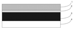
- the battery packaging material comprises a laminate in which at least a base material layer 1, an adhesive layer 2, a metal layer 3, and a sealant layer 4 are sequentially laminated.
- the base material layer 1 is the outermost layer
- the sealant layer 4 is the innermost layer. That is, when the battery is assembled, the sealant layers 4 positioned at the periphery of the battery element are thermally welded to seal the battery element, thereby sealing the battery element.
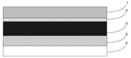
- the battery packaging material of the present invention is provided with an adhesive layer 5 between the metal layer 3 and the sealant layer 4 as necessary for the purpose of enhancing the adhesiveness thereof. May be.
- the base material layer 1 is a layer forming the outermost layer.
- the material for forming the base material layer 1 is not particularly limited as long as it has insulating properties.
- the material for forming the base material layer 1 include resin films such as polyester resin, polyamide resin, epoxy resin, acrylic resin, fluorine resin, polyurethane resin, silicon resin, phenol resin, and mixtures and copolymers thereof.
- the polyester resin include polyethylene terephthalate, polybutylene terephthalate, polyethylene naphthalate, polybutylene naphthalate, copolyester, and polycarbonate.
- polyamide resin examples include nylon 6, nylon 6,6, a copolymer of nylon 6 and nylon 6,6, nylon 6,10, polymetaxylylene adipamide (MXD6), and the like. It is done.
- nylon and polyester more preferably biaxially stretched nylon, biaxially stretched polyester, and particularly preferably biaxially stretched nylon.
- TS TD vertical direction tensile strength
- TS MD flow direction
- TD perpendicular
- the elongation (EL TD ) is preferably 90 to 110%, more preferably 95 to 100%.
- the ratio EL MD / EL TD is preferably 1.0 to 1.25, more preferably 1.0 to 1.2.
- the tensile strength (TS TD ) is preferably 280 to 370 MPa, more preferably 290 to 350 MPa.
- the ratio TS MD / TS TD is preferably 0.8 to 1.0, more preferably 0.9 to 1.0.
- the elongation (EL TD ), elongation (EL MD ), tensile strength (TS TD ) and tensile strength (TS MD ) specified in the above physical properties (i) and (ii) are the sample width 15 mm and the distance between the gauge points 100 mm. The value measured by a tensile test set at a tensile speed of 500 mm / min.
- the biaxially stretched nylon film having the above physical properties (i) and (ii) is known, and the production method thereof is also known.
- the biaxially stretched nylon film having such physical properties is, for example, stretched in the flow direction (MD) and the vertical direction (TD) with respect to an unstretched raw film made of a raw material containing nylon. It can be obtained by biaxially stretching under the condition that the magnification is 3.0 to 3.5 and then heat-treating at 150 to 200 ° C.
- a biaxial stretching method simultaneous biaxial stretching or sequential biaxial stretching by a tubular method or a tenter method can be adopted, and simultaneous biaxial stretching by a tubular method is preferable.
- the base material layer 1 may be formed of a single resin film, but may be formed of two or more resin films in order to improve pinhole resistance and insulation.
- the base material layer 1 is formed of a multilayer resin film, two or more resin films may be laminated via an adhesive, and the type and amount of the adhesive used will be described later. Or it is the same as the case of the adhesive layer 5.
- the thickness of the base material layer 1 is, for example, 10 to 50 ⁇ m, preferably 15 to 30 ⁇ m.
- the adhesive layer 2 is a layer provided between the base material layer 1 and the metal layer 3 in order to firmly bond them.
- the adhesive layer 2 is formed of an adhesive capable of adhering the base material layer 1 and the metal layer 3.
- the adhesive used for forming the adhesive layer 2 may be a two-component curable adhesive or a one-component curable adhesive.
- the adhesive mechanism of the adhesive used for forming the adhesive layer 2 is not particularly limited, and may be any of a chemical reaction type, a solvent volatilization type, a heat melting type, a hot pressure type, and the like.
- polyester resins such as polyethylene terephthalate, polybutylene terephthalate, polyethylene naphthalate, polybutylene naphthalate, polyethylene isophthalate, polycarbonate, and copolyester
- Polyether adhesive such as polyethylene terephthalate, polybutylene terephthalate, polyethylene naphthalate, polybutylene naphthalate, polyethylene isophthalate, polycarbon
- Polyolefin resins polyvinyl acetate resins, cellulose adhesives, (meth) acrylic resins, polyimide resins, urea resins, melamine resins and other amino resins, chloroprene rubber, nitrile rubber, - Len rubbers such as butadiene rubber, silicone-based resins.
- These adhesive components may be used individually by 1 type, and may be used in combination of 2 or more type. Among these adhesive components, a polyurethane-based adhesive is preferable.
- the thickness of the adhesive layer 2 is, for example, 1 to 10 ⁇ m, preferably 2 to 5 ⁇ m.
- the metal layer 3 is a layer that functions as a barrier layer for preventing the penetration of water vapor, oxygen, light, etc. into the battery, in addition to improving the strength of the packaging material.
- the metal layer 3 is formed of an aluminum foil having a 0.2% proof stress of 58 to 121 N / mm 2 when a tensile test in a direction parallel to the rolling direction is performed.
- the aluminum foil used as the metal layer 3 may satisfy the 0.2% proof stress of 58 to 121 N / mm 2 when a tensile test in the parallel direction (MD) to the rolling direction is performed. From the viewpoint of providing excellent moldability, the 0.2% proof stress is preferably 64 to 85 N / mm 2 .
- the 0.2% yield strength when a tensile test in the direction perpendicular to the rolling direction (TD) and 45 ° is performed is not particularly limited, but for example 50 to 130 N / mm 2 , preferably 60 ⁇ 90N / mm 2, more preferably include 65 ⁇ 85N / mm 2.
- the aluminum foil has a tensile strength at break when a tensile test in the direction parallel to the rolling direction (MD) is performed, for example, 90 to 130 N / mm 2 , preferably 95 to 125 N / mm 2 , more preferably 100 Up to 110 N / mm 2 .
- a tensile strength at break it becomes possible to provide excellent moldability more effectively.
- the tensile strength at break when the aluminum foil is subjected to a tensile test in the direction perpendicular to the rolling direction (TD) and 45 ° is not particularly limited, but is, for example, 90 to 124 N / mm 2 , preferably 94 to 122 N / mm 2 , more preferably 96 to 105 N / mm 2 .
- the 0.2% proof stress, tensile breaking strength, and tensile breaking elongation are values measured by a tensile test specified in JIS Z 2241.
- the aluminum foil used as the metal layer 3 may be pure aluminum alone as long as it has the 0.2% proof stress described above, but an aluminum alloy is preferable.
- Examples of the aluminum alloy used in the aluminum foil include an aluminum-Fe alloy, an aluminum-Mn alloy, and preferably an aluminum-Fe alloy.
- Preferable examples of the aluminum foil used as the metal layer 3 include soft aluminum, for example, annealed aluminum (JIS A8021H-O) or (JIS A8079H-O).
- Aluminum foils having the above characteristics are known and their production methods are also known. Specifically, the aluminum foil having such characteristics is, for example, a step of homogenizing an aluminum metal or aluminum alloy at a temperature of about 500 to 600 ° C. for about 1 to 2 hours, and a heat treatment at a temperature of about 400 to 500 ° C.
- the thickness of the metal layer 3 is, for example, 20 to 50 ⁇ m, preferably 30 to 40 ⁇ m.
- the metal layer 3 is preferably subjected to chemical conversion treatment on at least one surface, preferably both surfaces, for the purpose of stabilizing adhesion, preventing dissolution and corrosion, and the like.
- the chemical conversion treatment is a treatment for forming an acid-resistant film on the surface of the metal layer.
- the chemical conversion treatment is, for example, chromate chromate treatment using a chromic acid compound such as chromium nitrate, chromium fluoride, chromium sulfate, chromium acetate, chromium oxalate, chromium biphosphate, chromate acetylacetate, chromium chloride, potassium sulfate chromium, etc.
- Phosphoric acid chromate treatment using a phosphoric acid compound such as sodium phosphate, potassium phosphate, ammonium phosphate, polyphosphoric acid
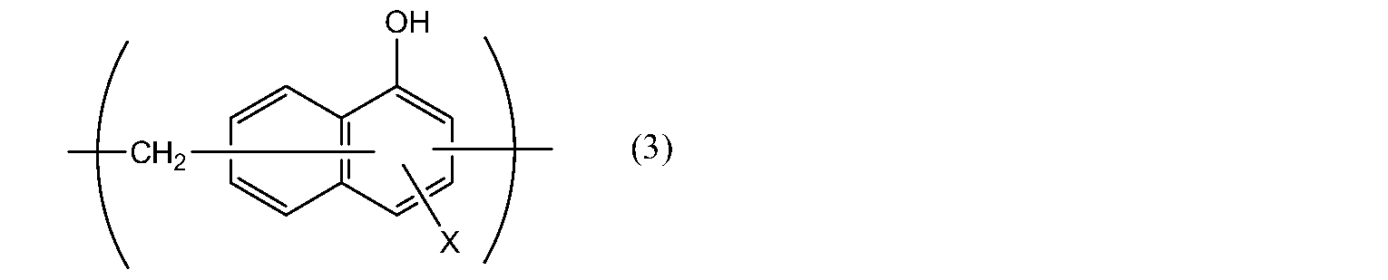
- aminated phenol heavy consisting of repeating units represented by the following general formulas (1) to (4) Examples thereof include chromate treatment using a coalescence.
- X represents a hydrogen atom, a hydroxyl group, an alkyl group, a hydroxyalkyl group, an allyl group or a benzyl group.
- R 1 and R 2 are the same or different and represent a hydroxyl group, an alkyl group, or a hydroxyalkyl group.
- examples of the alkyl group represented by X, R 1 and R 2 include a methyl group, an ethyl group, an n-propyl group, an isopropyl group, an n-butyl group, an isobutyl group, Examples thereof include a linear or branched alkyl group having 1 to 4 carbon atoms such as a tert-butyl group.
- Examples of the hydroxyalkyl group represented by X, R 1 and R 2 include a hydroxymethyl group, a 1-hydroxyethyl group, a 2-hydroxyethyl group, a 1-hydroxypropyl group, a 2-hydroxypropyl group, 3- A straight or branched chain having 1 to 4 carbon atoms substituted with one hydroxy group such as hydroxypropyl group, 1-hydroxybutyl group, 2-hydroxybutyl group, 3-hydroxybutyl group, 4-hydroxybutyl group An alkyl group is mentioned.
- X is preferably any one of a hydrogen atom, a hydroxyl group, and a droxyalkyl group.
- the number average molecular weight of the aminated phenol polymer comprising the repeating units represented by the general formulas (1) to (4) is, for example, about 500 to about 1,000,000, preferably about 1,000 to about 20,000.
- a metal oxide such as aluminum oxide, titanium oxide, cerium oxide, tin oxide, or barium sulfate fine particles dispersed in phosphoric acid is coated.
- a method of forming a corrosion-resistant treatment layer on the surface of the metal layer 3 by performing a baking treatment at 150 ° C. or higher can be mentioned.
- a resin layer obtained by crosslinking a cationic polymer with a crosslinking agent may be formed on the corrosion-resistant treatment layer.
- the cationic polymer for example, polyethyleneimine, an ionic polymer complex composed of a polymer having polyethyleneimine and a carboxylic acid, a primary amine-grafted acrylic resin in which a primary amine is grafted on an acrylic main skeleton, polyallylamine, or Examples thereof include aminophenols and derivatives thereof.
- These cationic polymers may be used individually by 1 type, and may be used in combination of 2 or more type.
- the crosslinking agent include compounds having at least one functional group selected from the group consisting of isocyanate groups, glycidyl groups, carboxyl groups, and oxazoline groups, silane coupling agents, and the like. These crosslinking agents may be used alone or in combination of two or more.
- These chemical conversion treatments may be performed alone or in combination of two or more chemical conversion treatments. Furthermore, these chemical conversion treatments may be carried out using one kind of compound alone, or may be carried out using a combination of two or more kinds of compounds. Among these, chromic acid chromate treatment is preferable, and chromate treatment in which a chromic acid compound, a phosphoric acid compound, and the aminated phenol polymer are combined is more preferable.
- the amount of the acid-resistant film to be formed on the surface of the metal layer 3 in the chemical conversion treatment is not particularly limited.
- the chromate treatment may be performed by combining a chromic acid compound, a phosphoric acid compound, and the aminated phenol polymer.
- the chromate compound is about 0.5 to about 50 mg, preferably about 1.0 to about 40 mg in terms of chromium
- the phosphorus compound is about 0.5 to about 50 mg in terms of phosphorus per 1 m 2 of the surface of the metal layer. Is about 1.0 to about 40 mg
- the aminated phenol polymer is contained in an amount of about 1 to about 200 mg, preferably about 5.0 to 150 mg.
- a solution containing a compound used for forming an acid-resistant film is applied to the surface of the metal layer by a bar coating method, a roll coating method, a gravure coating method, an immersion method or the like, and then the temperature of the metal layer is 70. It is performed by heating to about 200 ° C.
- the metal layer may be previously subjected to a degreasing treatment by an alkali dipping method, an electrolytic cleaning method, an acid cleaning method, an electrolytic acid cleaning method, or the like. By performing the degreasing treatment in this way, it becomes possible to perform the chemical conversion treatment of the surface of the metal layer more efficiently.
- the sealant layer 4 corresponds to the innermost layer, and is a layer that seals the battery element by heat-sealing the sealant layers when the battery is assembled.
- the resin component used for the sealant layer 4 is not particularly limited as long as it can be thermally welded, and examples thereof include polyolefin, cyclic polyolefin, carboxylic acid-modified polyolefin, and carboxylic acid-modified cyclic polyolefin.
- polystyrene resin examples include polyethylene such as low density polyethylene, medium density polyethylene, high density polyethylene, and linear low density polyethylene; homopolypropylene, polypropylene block copolymer (for example, block copolymer of propylene and ethylene), polypropylene And a random copolymer (eg, a random copolymer of propylene and ethylene); an ethylene-butene-propylene terpolymer; and the like.
- polyethylene and polypropylene are preferable.
- the cyclic polyolefin is a copolymer of an olefin and a cyclic monomer
- examples of the olefin that is a constituent monomer of the cyclic polyolefin include ethylene, propylene, 4-methyl-1-pentene, styrene, butadiene, and isoprene. Is mentioned.
- Examples of the cyclic monomer that is a constituent monomer of the cyclic polyolefin include cyclic alkenes such as norbornene; specifically, cyclic dienes such as cyclopentadiene, dicyclopentadiene, cyclohexadiene, and norbornadiene.
- cyclic alkene is preferable, and norbornene is more preferable.
- the carboxylic acid-modified polyolefin is a polymer modified by block polymerization or graft polymerization of the polyolefin with carboxylic acid.
- Examples of the carboxylic acid used for modification include maleic acid, acrylic acid, itaconic acid, crotonic acid, maleic anhydride, itaconic anhydride and the like.
- the carboxylic acid-modified cyclic polyolefin is obtained by copolymerizing a part of the monomer constituting the cyclic polyolefin in place of the ⁇ , ⁇ -unsaturated carboxylic acid or its anhydride, or ⁇ , ⁇ with respect to the cyclic polyolefin.
- -A polymer obtained by block polymerization or graft polymerization of an unsaturated carboxylic acid or its anhydride.
- the cyclic polyolefin to be modified with carboxylic acid is the same as described above.
- the carboxylic acid used for modification is the same as that used for modification of the acid-modified cycloolefin copolymer.
- carboxylic acid-modified polyolefin is preferable; carboxylic acid-modified polypropylene is more preferable.
- the sealant layer 4 may be formed of one kind of resin component alone, or may be formed of a blend polymer in which two or more kinds of resin components are combined. Furthermore, the sealant layer 4 may be formed of only one layer, but may be formed of two or more layers using the same or different resin components.
- the thickness of the sealant layer 4 can be selected as appropriate, but is 10 to 100 ⁇ m, preferably 15 to 50 ⁇ m.
- the adhesive layer 5 is a layer provided between the metal layer 3 and the sealant layer 4 as necessary in order to firmly bond them.
- the adhesive layer 5 is formed of an adhesive capable of bonding the metal layer 3 and the sealant layer 4. With respect to the adhesive used for forming the adhesive layer 5, the adhesive mechanism, the types of adhesive components, and the like are the same as those of the adhesive layer 2.
- the adhesive component used for the adhesive layer 5 is preferably a polyolefin resin, more preferably a carboxylic acid-modified polyolefin, particularly preferably a carboxylic acid-modified polypropylene.
- the thickness of the adhesive layer 5 is, for example, 10 to 50 ⁇ m, preferably 20 to 30 ⁇ m.
- the method for producing the battery packaging material of the present invention is not particularly limited as long as a laminate in which layers having a predetermined composition are laminated is obtained.
- the following method is exemplified. .
- laminated body A a laminated body in which the base material layer 1, the adhesive layer 2, and the metal layer 3 are laminated in this order (hereinafter also referred to as “laminated body A”) is formed.
- the laminate A is formed by extruding an adhesive used for forming the adhesive layer 2 on the base layer 1 or the metal layer 3 whose surface is subjected to chemical conversion treatment, if necessary. It can be performed by a dry lamination method in which the metal layer 3 or the base material layer 1 is laminated and the adhesive layer 2 is cured after being applied and dried by a coating method such as a method or a roll coating method.
- the sealant layer 4 is laminated on the metal layer 3 of the laminate A.
- the resin component constituting the sealant layer 4 may be applied on the metal layer 3 of the laminate A by a method such as a gravure coating method or a roll coating method.
- the adhesive layer 5 is provided between the metal layer 3 and the sealant layer 4, for example, (1) the adhesive layer 5 and the sealant layer 4 are laminated on the metal layer 3 of the laminate A by coextrusion.
- a laminate composed of base material layer 1 / adhesive layer 2 / metal layer 3 whose surface is subjected to chemical conversion treatment as necessary / adhesive layer 5 / sealant layer 4 provided as necessary is formed.
- a heat treatment such as a hot roll contact type, a hot air type, a near or far infrared type.
- An example of such heat treatment conditions is 150 to 250 ° C. for 1 to 5 minutes.
- each layer constituting the laminate improves or stabilizes film forming properties, lamination processing, suitability for final processing (pouching, embossing), etc., as necessary. Therefore, surface activation treatment such as corona treatment, blast treatment, oxidation treatment, ozone treatment may be performed.
- the battery packaging material of the present invention is used as a packaging material for sealing and housing battery elements such as a positive electrode, a negative electrode, and an electrolyte.
- a battery element including at least a positive electrode, a negative electrode, and an electrolyte is formed using the battery packaging material of the present invention, with the metal terminals connected to each of the positive electrode and the negative electrode protruding outward.
- a battery using a battery packaging material is formed by covering the periphery of the element so that a flange portion (a region where the sealant layers are in contact with each other) can be formed, and heat-sealing and sealing the sealant layers of the flange portion.
- the battery packaging material of the present invention is used such that the sealant portion is on the inner side (surface in contact with the battery element).
- the battery packaging material of the present invention may be used for either a primary battery or a secondary battery, but is preferably a secondary battery.
- the type of secondary battery to which the battery packaging material of the present invention is applied is not particularly limited.
- a lithium ion battery, a lithium ion polymer battery, a lead battery, a nickel / hydrogen battery, a nickel / cadmium battery , Nickel / iron livestock batteries, nickel / zinc livestock batteries, silver oxide / zinc livestock batteries, metal-air batteries, polyvalent cation batteries, capacitors, capacitors and the like are suitable applications for the battery packaging material of the present invention.
- Examples 1 to 18 and Comparative Examples 1 to 3 ⁇ Manufacture of battery packaging materials>
- the adhesive layer 5 and the sealant layer 4 by the thermal laminating method on the laminate in which the base material layer 1 / adhesive layer 2 / metal layer 3 are sequentially laminated, the base material layer 1 / adhesive layer 2 / metal.
- a battery packaging material comprising a laminate in which layer 3 / adhesive layer 5 / sealant layer 4 were sequentially laminated was produced.
- the manufacturing conditions of the battery packaging material are as follows.
- the elongation rate (EL TD ), the elongation rate (EL MD ), the tensile strength (TS TD ), and the tensile strength (TS MD ) of the nylon films 1, 2, and 3 are measured using a precision universal testing machine (Autograph).
- the sample width was 15 mm
- the distance between the gauge points was 100 mm
- the tensile speed was set to 500 mm / min.
- AL foils 1 to 9 (thickness 40 ⁇ m) made of soft aluminum ((JIS H4160, A8021H-O) having physical properties shown in Table 1 were used.
- the chemical conversion treatment of the foils 1 to 9 is performed by applying a treatment liquid composed of a phenol resin, a chromium fluoride compound, and phosphoric acid on both surfaces of the metal layer by a roll coating method, and baking for 20 seconds under the condition that the film temperature is 180 ° C. or higher. It was done by doing.
- the 0.2% proof stress, tensile breaking strength, and tensile breaking elongation of the AL foils 1 to 9 were measured by a tensile test specified in JIS Z 2241.
- a laminate in which the base material layer 1 / adhesive layer 2 / metal layer 3 were laminated in order by the combination of the base material layer 1 and the metal layer 3 shown in Table 2 was produced.
- an adhesive layer 2 made of a two-component urethane adhesive of a polyester main agent and an isocyanic curing agent is formed on one surface of the base material layer 1 so as to have a thickness of 3 ⁇ m, and a chemical conversion treatment surface of the metal layer.
- a laminated body in which base material layer 1 / adhesive layer 2 / metal layer 3 were laminated in order was produced by pressure and heat bonding.
- acid-modified polypropylene resin constituting the adhesive layer 5 [unsaturated carboxylic acid graft-modified random polypropylene graft-modified with unsaturated carboxylic acid, and polypropylene constituting the sealant layer 4 [random copolymer (hereinafter referred to as PP]).
- PP random copolymer
- the metal layer 3 was laminated so that the adhesive layer 5 of the two-layer coextruded film prepared above was in contact with the metal layer of the laminate composed of the base material layer 1 / adhesive layer 2 / metal layer 3 prepared above.
- the packaging material for batteries was obtained by hold
- the battery packaging material obtained above was cut into 120 ⁇ 80 mm strips, which were used as test samples.
- a straight mold composed of a 30 ⁇ 50 mm rectangular male mold and a female mold with a clearance of 0.5 mm between the male mold and the above, the thermal adhesive resin layer side is positioned on the male mold side.
- the test sample was placed, and the test sample was pressed with a presser pressure (surface pressure) of 0.1 MPa so as to have a molding depth of 6 mm or 7 mm, and cold-molded (drawn one-step molding).
- the molding under the condition that the molding depth is 6 mm is performed using the battery packaging materials of Example 1-6 and Comparative Example 1-3, and the molding under the condition where the molding depth is 7 mm is performed in Example 1. It was carried out using -18 battery packaging materials. The presence or absence of pinholes and cracks in the metal layer in the molded battery packaging material was confirmed, and the pinhole and crack generation rates (%) were calculated. The rate of occurrence of pinholes and cracks was determined when molding was performed when 30 test samples were molded under the above conditions, with pinholes or cracks observed even at one location after molding as a defective molding. Calculated as the percentage of defective products.
- Table 3 shows the results when molding is performed under conditions where the molding depth is 6 mm
- Table 4 shows the results when molding is performed under conditions where the molding depth is 7 mm.
- the 0.2% proof stress in the direction parallel to the rolling direction has a high proof strength of 58 to 121 N / mm 2 , particularly 64 to 85 N / mm 2.
- the 0.2% proof stress in the parallel direction to the rolling direction is less than 58N / mm 2, and in the case of using 121N / mm 2 greater than the aluminum foil, when molded in the molding depth 6 mm, pinholes and cracks
- the generation rate was high and inferior in formability as compared with Example 1-6.
Landscapes
- Chemical & Material Sciences (AREA)
- Chemical Kinetics & Catalysis (AREA)
- Electrochemistry (AREA)
- General Chemical & Material Sciences (AREA)
- Inorganic Chemistry (AREA)
- Sealing Battery Cases Or Jackets (AREA)
- Laminated Bodies (AREA)
Abstract
Description
項1. 少なくとも、基材層、接着層、金属層、及びシーラント層が順次積層された積層体からなり、前記金属層が、圧延方向に対して平行方向の引張試験を行った時の0.2%耐力が58~121N/mm2であるアルミニウム箔であることを特徴とする、電池用包装材料。
項2. 前記基材層が、下記(i)と(ii)の物性を満たす2軸延伸ナイロンフィルムである、項1に記載の電池用包装材料。
(i)幅方向の伸び率(ELTD)が80~120%であり、且つ流れ方向の伸び率(ELMD)と幅方向の伸び率(ELTD)の比ELMD/ELTDが1~1.25である。
(ii)垂直方向の引張強度(TSTD)が280MPa以上であり、且つ流れ方向の引張強度(TSMD)と垂直方向の引張強度(TSTD)の比TSMD/TSTDが0.75~1である。
項3. 前記アルミニウム箔が、圧延方向に対して垂直方向及び45°方向の引張試験を行った時の0.2%耐力が共に50~130N/mm2を満たす、項1又は2に記載の電池用包装材料。
項4. 前記アルミニウム箔が、圧延方向に対して平行方向の引張試験を行った時の引張破断強度が90~130N/mm2を満たす、項1~3のいずれかに記載の電池用包装材料。
項5. 前記金属層の少なくとも一方の面に化成処理が施されている、項1~4のいずれかに記載の電池用包装材料。
項6. 二次電池用の包装材料である、項1~5のいずれかに記載の電池用包装材料。
項7. 少なくとも正極、負極、及び電解質を備えた電池素子が、項1~6のいずれかに記載の電池用包装材料内に収容されている、電池。
項8. 電池の製造方法であって、
少なくとも正極、負極、及び電解質を備えた電池素子を電池用包装材料で収容する工程を含み、
前記電池用包装材料は、少なくとも、基材層、接着層、金属層、及びシーラント層が順次積層された積層体からなり、前記金属層が、圧延方向に対して平行方向の引張試験を行った時の0.2%耐力が58~121N/mm2であるアルミニウム箔である、電池の製造方法。
項9. 少なくとも、基材層、接着層、金属層、及びシーラント層が順次積層された積層体からなり、前記金属層が、圧延方向に対して平行方向の引張試験を行った時の0.2%耐力が58~121N/mm2であるアルミニウム箔である包装材料の、電池の製造のための使用。 That is, this invention provides the battery packaging material and battery of the aspect hung up below.
(i) Elongation in the width direction (EL TD ) is 80 to 120%, and the ratio EL MD / EL TD between the elongation in the flow direction (EL MD ) and the elongation in the width direction (EL TD ) is 1 to 1.25.
(ii) The tensile strength (TS TD ) in the vertical direction is 280 MPa or more, and the ratio TS MD / TS TD between the tensile strength (TS MD ) in the flow direction and the tensile strength (TS TD ) in the vertical direction is 0.75 to 1.
Item 6. Item 6. The battery packaging material according to any one of
Item 7. Item 7. A battery in which a battery element including at least a positive electrode, a negative electrode, and an electrolyte is accommodated in the battery packaging material according to any one of
Item 8. A battery manufacturing method comprising:
Including at least a positive electrode, a negative electrode, and a battery element containing an electrolyte in a battery packaging material,
The battery packaging material is composed of a laminate in which at least a base material layer, an adhesive layer, a metal layer, and a sealant layer are sequentially laminated, and the metal layer was subjected to a tensile test in a direction parallel to the rolling direction. A method for producing a battery, which is an aluminum foil having a 0.2% proof stress of 58 to 121 N / mm 2 .
Item 9. At least a base material layer, an adhesive layer, a metal layer, and a sealant layer are sequentially laminated, and the metal layer has a 0.2% yield strength when subjected to a tensile test in a direction parallel to the rolling direction. Use of a packaging material, which is an aluminum foil, having an A of 58 to 121 N / mm 2 for the manufacture of a battery.
電池用包装材料は、図1に示すように、少なくとも、基材層1、接着層2、金属層3、及びシーラント層4が順次積層された積層体からなる。本発明の電池用包装材料において、基材層1が最外層になり、シーラント層4は最内層になる。即ち、電池の組み立て時に、電池素子の周縁に位置するシーラント層4同士が熱溶着して電池素子を密封することにより、電池素子が封止される。 1. As shown in FIG. 1, the battery packaging material comprises a laminate in which at least a
[基材層1]
本発明の電池用包装材料において、基材層1は最外層を形成する層である。基材層1を形成する素材については、絶縁性を備えるものであることを限度として特に制限されるものではない。基材層1を形成する素材としては、例えば、ポリエステル樹脂、ポリアミド樹脂、エポキシ樹脂、アクリル樹脂、フッ素樹脂、ポリウレタン樹脂、珪素樹脂、フェノール樹脂、及びこれらの混合物や共重合物等の樹脂フィルムが挙げられる。ポリエステル樹脂としては、具体的には、ポリエチレンテレフタレート、ポリブチレンテレフタレート、ポリエチレンナフタレート、ポリブチレンナフタレート、共重合ポリエステル、ポリカーボネート等が挙げられる。また、ポリアミド樹脂としては、具体的には、ナイロン6、ナイロン6,6、ナイロン6とナイロン6,6との共重合体、ナイロン6,10、ポリメタキシリレンアジパミド(MXD6)等が挙げられる。これらの中でも、好ましくはナイロン、ポリエステル、更に好ましくは2軸延伸ナイロン、2軸延伸ポリエステル、特に好ましくは2軸延伸ナイロンが挙げられる。 2. Composition of each layer forming base material for battery [base material layer 1]
In the battery packaging material of the present invention, the
(i)垂直方向(TD)の伸び率(ELTD)が80~120%であり、且つ流れ方向(MD)の伸び率(ELMD)と垂直方向(TD)の伸び率(ELTD)の比ELMD/ELTDが1~1.25である。
(ii)垂直方向(TD)の引張強度(TSTD)が280MPa以上であり、且つ流れ方向(MD)の引張強度(TSMD)と垂直方向(TD)の引張強度(TSTD)の比TSMD/TSTDが0.75~1である。 Among the above-mentioned biaxially stretched nylon films, in particular, when a material satisfying the following physical properties (i) and (ii) is used, the stress concentration due to non-uniform deformation that occurs at the time of molding in the battery packaging material of the present invention can be made even more effective. Therefore, it is possible to enhance the action of uniformly deforming, to further effectively suppress the generation of pinholes and cracks during molding, and to significantly improve the moldability.
(i) elongation in the vertical direction (TD) (EL TD) is 80 to 120% and elongation of elongation in the flow direction (MD) (EL MD) and perpendicular (TD) of (EL TD) The ratio EL MD / EL TD is 1 to 1.25.
(ii) it is in the vertical direction (TD) tensile strength (TS TD) is 280MPa or more, and the ratio TS of the tensile strength of the tensile strength in the flow direction (MD) (TS MD) and perpendicular (TD) (TS TD) MD / TS TD is 0.75 to 1.
本発明の電池用包装材料において、接着層2は、基材層1と金属層3を強固に接着させために、これらの間に設けられる層である。 [Adhesive layer 2]
In the battery packaging material of the present invention, the
本発明の電池用包装材料において、金属層3は、包装材料の強度向上の他、電池内部に水蒸気、酸素、光等が侵入するのを防止するためのバリア層として機能する層である。本発明の電池用包装材料において、金属層3は、圧延方向に対して平行方向の引張試験を行った時の0.2%耐力が58~121N/mm2であるアルミニウム箔によって形成される。このように耐力が高いアルミニウム箔を金属層3として使用することによって、本発明の電池用包装材料に優れた成形性を備えさえることができる。 [Metal layer 3]
In the battery packaging material of the present invention, the


本発明の電池用包装材料において、シーラント層4は、最内層に該当し、電池の組み立て時にシーラント層同士が熱溶着して電池素子を密封する層である。 [Sealant layer 4]
In the battery packaging material of the present invention, the
本発明の電池用包装材料において、接着層5は、金属層3とシーラント層4を強固に接着させために、これらの間に必要に応じて設けられる層である。 [Adhesive layer 5]
In the battery packaging material of the present invention, the
本発明の電池用包装材料の製造方法については、所定の組成の各層を積層させた積層体が得られる限り、特に制限されないが、例えば、以下の方法が例示される。 3. Method for Producing Battery Packaging Material The method for producing the battery packaging material of the present invention is not particularly limited as long as a laminate in which layers having a predetermined composition are laminated is obtained. For example, the following method is exemplified. .
本発明の電池用包装材料は、正極、負極、電解質等の電池素子を密封して収容するための包装材料として使用される。 4). Application of Battery Packaging Material The battery packaging material of the present invention is used as a packaging material for sealing and housing battery elements such as a positive electrode, a negative electrode, and an electrolyte.
<電池用包装材料の製造>
基材層1/接着層2/金属層3が順に積層された積層体に対して、サーマルラミネート法で接着層5及びシーラント層4を積層させることにより、基材層1/接着層2/金属層3/接着層5/シーラント層4が順に積層された積層体からなる電池用包装材料を製造した。電池用包装材料の製造条件は、以下に示す通りである。 Examples 1 to 18 and Comparative Examples 1 to 3
<Manufacture of battery packaging materials>
By laminating the
・ナイロンフィルム1
2軸延伸ナイロンフィルム:ナイロン6
厚さ:25μm
垂直方向(TD)の伸び率(ELTD):110%
流れ方向(MD)の伸び率(ELMD):140%
比ELMD/ELTD:1.28
垂直方向(TD)の引張強度(TSTD):270MPa
流れ方向(MD)の引張強度(TSMD):260MPa
比TSMD/TSTD:0.96
・ナイロンフィルム2
2軸延伸ナイロンフィルム:ナイロン6
厚さ:25μm
垂直方向(TD)の伸び率(ELTD):100%
流れ方向(MD)の伸び率(ELMD):110%
比ELMD/ELTD:1.10
垂直方向(TD)の引張強度(TSTD):350MPa
流れ方向(MD)の引張強度(TSMD):330MPa
比TSMD/TSTD:0.94
・ナイロンフィルム3
2軸延伸ナイロンフィルム:ナイロン6
厚さ:25μm
垂直方向(TD)の伸び率(ELTD):100%
流れ方向(MD)の伸び率(ELMD):120%
比ELMD/ELTD:1.20
垂直方向(TD)の引張強度(TSTD):300MPa
流れ方向(MD)の引張強度(TSMD):270MPa
比TSMD/TSTD:0.90
上記ナイロンフィルム1、2及び3は、ナイロンを含む原料からなる未延伸原反フィルムに対して、流れ方向(MD)及び幅方向(TD)のそれぞれの延伸倍率が3.0~3.5倍となる条件でチューブラー法による同時二軸延伸した後、150~200℃で熱処理することで製造したものである。 The following
・
Biaxially stretched nylon film: Nylon 6
Thickness: 25μm
Elongation rate in the vertical direction (TD) (EL TD ): 110%
Elongation rate in the flow direction (MD) (EL MD ): 140%
Ratio EL MD / EL TD : 1.28
Tensile strength (TS TD ) in the vertical direction (TD): 270 MPa
Tensile strength (TS MD ) in the flow direction (MD): 260 MPa
The ratio TS MD / TS TD: 0.96
・
Biaxially stretched nylon film: Nylon 6
Thickness: 25μm
Elongation rate in the vertical direction (TD) (EL TD ): 100%
Elongation rate in the flow direction (MD) (EL MD ): 110%
Ratio EL MD / EL TD : 1.10
Tensile strength (TS TD ) in the vertical direction (TD): 350 MPa
Tensile strength (TS MD ) in the flow direction (MD): 330 MPa
The ratio TS MD / TS TD: 0.94
・
Biaxially stretched nylon film: Nylon 6
Thickness: 25μm
Elongation rate in the vertical direction (TD) (EL TD ): 100%
Elongation rate in the flow direction (MD) (EL MD ): 120%
Ratio EL MD / EL TD : 1.20
Tensile strength (TS TD ) in the vertical direction (TD): 300 MPa
Tensile strength (TS MD ) in the flow direction (MD): 270 MPa
The ratio TS MD / TS TD: 0.90
The


上記で得られた電池用包装材料を裁断して、120×80mmの短冊片を作製し、これを試験サンプルとした。30×50mmの矩形状の雄型とこの雄型とのクリアランスが0.5mmの雌型からなるストレート金型を用い、雄型側に熱接着性樹脂層側が位置するように雌型上に上記試験サンプルを載置し、成形深さ6mm又は7mmとなるように当該試験サンプルを0.1MPaの押え圧(面圧)で押えて、冷間成形(引き込み1段成形)した。なお、成形深さ6mmになる条件での成形は、実施例1-6及び比較例1-3の電池用包装材料を用いて行い、成形深さ7mmになる条件での成形は、実施例1-18の電池用包装材料を用いて行った。成形された電池用包装材料における金属層のピンホール及びクラックの発生の有無を確認し、ピンホール及びクラックの発生率(%)を算出した。ピンホール及びクラックの発生率は、上記成形を行った後に1カ所でもピンホール又はクラックが認められるものを成形不良品として判別し、30個の試験サンプルを上記条件で成形した際に発生した成形不良品の割合として求めた。 <Evaluation of formability>
The battery packaging material obtained above was cut into 120 × 80 mm strips, which were used as test samples. Using a straight mold composed of a 30 × 50 mm rectangular male mold and a female mold with a clearance of 0.5 mm between the male mold and the above, the thermal adhesive resin layer side is positioned on the male mold side. The test sample was placed, and the test sample was pressed with a presser pressure (surface pressure) of 0.1 MPa so as to have a molding depth of 6 mm or 7 mm, and cold-molded (drawn one-step molding). The molding under the condition that the molding depth is 6 mm is performed using the battery packaging materials of Example 1-6 and Comparative Example 1-3, and the molding under the condition where the molding depth is 7 mm is performed in Example 1. It was carried out using -18 battery packaging materials. The presence or absence of pinholes and cracks in the metal layer in the molded battery packaging material was confirmed, and the pinhole and crack generation rates (%) were calculated. The rate of occurrence of pinholes and cracks was determined when molding was performed when 30 test samples were molded under the above conditions, with pinholes or cracks observed even at one location after molding as a defective molding. Calculated as the percentage of defective products.


2 接着層
3 金属層
4 シーラント層
5 接着層 1
Claims (7)
- 少なくとも、基材層、接着層、金属層、及びシーラント層が順次積層された積層体からなり、前記金属層が、圧延方向に対して平行方向の引張試験を行った時の0.2%耐力が58~121N/mm2であるアルミニウム箔であることを特徴とする、電池用包装材料。 At least a base material layer, an adhesive layer, a metal layer, and a sealant layer are sequentially laminated, and the metal layer has a 0.2% yield strength when subjected to a tensile test in a direction parallel to the rolling direction. A battery packaging material characterized by being an aluminum foil having a thickness of 58 to 121 N / mm 2 .
- 前記基材層が、下記(i)と(ii)の物性を満たす2軸延伸ナイロンフィルムである、請求項1に記載の電池用包装材料。
(i)幅方向の伸び率(ELTD)が80~120%であり、且つ流れ方向の伸び率(ELMD)と幅方向の伸び率(ELTD)の比ELMD/ELTDが1~1.25である。
(ii)幅方向の引張強度(TSTD)が280MPa以上であり、且つ流れ方向の引張強度(TSMD)と垂直方向の引張強度(TSTD)の比TSMD/TSTDが0.75~1である。 The battery packaging material according to claim 1, wherein the base material layer is a biaxially stretched nylon film satisfying the following physical properties (i) and (ii).
(i) Elongation in the width direction (EL TD ) is 80 to 120%, and the ratio EL MD / EL TD between the elongation in the flow direction (EL MD ) and the elongation in the width direction (EL TD ) is 1 to 1.25.
(ii) The tensile strength (TS TD ) in the width direction is 280 MPa or more, and the ratio TS MD / TS TD between the tensile strength (TS MD ) in the flow direction and the tensile strength (TS TD ) in the vertical direction is 0.75 to 1. - 前記アルミニウム箔が、圧延方向に対して垂直方向及び45°方向の引張試験を行った時の0.2%耐力が共に50~130N/mm2を満たす、請求項1又は2に記載の電池用包装材料。 The battery according to claim 1 or 2, wherein the aluminum foil has a 0.2% proof stress satisfying 50 to 130 N / mm 2 when subjected to a tensile test in a direction perpendicular to the rolling direction and in a 45 ° direction. Packaging material.
- 前記アルミニウム箔が、圧延方向に対して平行方向の引張試験を行った時の引張破断強度が90~130N/mm2を満たす、請求項1~3のいずれかに記載の電池用包装材料。 The battery packaging material according to any one of claims 1 to 3, wherein the aluminum foil satisfies a tensile breaking strength of 90 to 130 N / mm 2 when a tensile test in a direction parallel to the rolling direction is performed.
- 前記金属層の少なくとも一方の面に化成処理が施されている、請求項1~4のいずれかに記載の電池用包装材料。 The battery packaging material according to any one of claims 1 to 4, wherein at least one surface of the metal layer is subjected to a chemical conversion treatment.
- 二次電池用の包装材料である、請求項1~5のいずれかに記載の電池用包装材料。 The battery packaging material according to any one of claims 1 to 5, which is a packaging material for a secondary battery.
- 少なくとも正極、負極、及び電解質を備えた電池素子が、請求項1~6のいずれかに記載の電池用包装材料内に収容されている、電池。 A battery in which a battery element including at least a positive electrode, a negative electrode, and an electrolyte is accommodated in the battery packaging material according to any one of claims 1 to 6.
Priority Applications (7)
| Application Number | Priority Date | Filing Date | Title |
|---|---|---|---|
| KR1020147036981A KR101494589B1 (en) | 2012-06-04 | 2013-05-29 | Packaging material for cell |
| US14/405,524 US9520581B2 (en) | 2012-06-04 | 2013-05-29 | Packaging material for cell |
| JP2013533027A JP5447742B1 (en) | 2012-06-04 | 2013-05-29 | Battery packaging materials |
| EP13800865.1A EP2858138B1 (en) | 2012-06-04 | 2013-05-29 | Packaging material for cell |
| CN201380029612.7A CN104364929B (en) | 2012-06-04 | 2013-05-29 | Battery use packing material |
| HK15105410.4A HK1205358A1 (en) | 2012-06-04 | 2015-06-08 | Packaging material for cell |
| US15/341,206 US10381611B2 (en) | 2012-06-04 | 2016-11-02 | Packaging material for cell |
Applications Claiming Priority (2)
| Application Number | Priority Date | Filing Date | Title |
|---|---|---|---|
| JP2012-127344 | 2012-06-04 | ||
| JP2012127344 | 2012-06-04 |
Related Child Applications (2)
| Application Number | Title | Priority Date | Filing Date |
|---|---|---|---|
| US14/405,524 A-371-Of-International US9520581B2 (en) | 2012-06-04 | 2013-05-29 | Packaging material for cell |
| US15/341,206 Division US10381611B2 (en) | 2012-06-04 | 2016-11-02 | Packaging material for cell |
Publications (1)
| Publication Number | Publication Date |
|---|---|
| WO2013183511A1 true WO2013183511A1 (en) | 2013-12-12 |
Family
ID=49711903
Family Applications (1)
| Application Number | Title | Priority Date | Filing Date |
|---|---|---|---|
| PCT/JP2013/064859 WO2013183511A1 (en) | 2012-06-04 | 2013-05-29 | Packaging material for cell |
Country Status (7)
| Country | Link |
|---|---|
| US (2) | US9520581B2 (en) |
| EP (1) | EP2858138B1 (en) |
| JP (1) | JP5447742B1 (en) |
| KR (1) | KR101494589B1 (en) |
| CN (2) | CN104364929B (en) |
| HK (1) | HK1205358A1 (en) |
| WO (1) | WO2013183511A1 (en) |
Cited By (14)
| Publication number | Priority date | Publication date | Assignee | Title |
|---|---|---|---|---|
| WO2015087901A1 (en) * | 2013-12-11 | 2015-06-18 | 大日本印刷株式会社 | Packaging material for battery |
| JP2015123706A (en) * | 2013-12-27 | 2015-07-06 | 株式会社Uacj製箔 | Aluminum foil-made packaging material |
| US20150214515A1 (en) * | 2014-01-29 | 2015-07-30 | Benq Materials Corporation | Packaging film for battery |
| WO2016031758A1 (en) * | 2014-08-28 | 2016-03-03 | 大日本印刷株式会社 | Packaging material for battery |
| WO2016047790A1 (en) * | 2014-09-26 | 2016-03-31 | 大日本印刷株式会社 | Battery packaging material |
| JP2016048658A (en) * | 2014-08-28 | 2016-04-07 | 大日本印刷株式会社 | Packaging material for battery |
| JP2016071952A (en) * | 2014-09-26 | 2016-05-09 | 大日本印刷株式会社 | Battery-packaging material |
| WO2016158796A1 (en) * | 2015-03-27 | 2016-10-06 | 大日本印刷株式会社 | Packaging material for batteries, method for producing same, and battery |
| KR20160129054A (en) * | 2014-03-03 | 2016-11-08 | 다이니폰 인사츠 가부시키가이샤 | Battery packaging material |
| JP2016207666A (en) * | 2016-09-07 | 2016-12-08 | 大日本印刷株式会社 | Packaging material for battery |
| JP2016207665A (en) * | 2016-09-07 | 2016-12-08 | 大日本印刷株式会社 | Battery-packaging material |
| WO2017110062A1 (en) * | 2015-12-25 | 2017-06-29 | パナソニックIpマネジメント株式会社 | Film material for battery exterior, and flexible battery including same |
| JP2018110134A (en) * | 2018-04-05 | 2018-07-12 | 大日本印刷株式会社 | Battery-packaging material |
| JP2019091718A (en) * | 2019-03-07 | 2019-06-13 | 大日本印刷株式会社 | Battery packaging material |
Families Citing this family (8)
| Publication number | Priority date | Publication date | Assignee | Title |
|---|---|---|---|---|
| JPWO2014084248A1 (en) * | 2012-11-30 | 2017-01-05 | ユニチカ株式会社 | Cold forming packaging material and press-through pack using the same |
| CN105794012B (en) * | 2013-12-02 | 2019-06-25 | 大日本印刷株式会社 | Battery use packing material |
| DE102015224785A1 (en) * | 2015-12-10 | 2017-06-14 | Bayerische Motoren Werke Aktiengesellschaft | Cell contacting system, cell module and method of manufacturing a cell module |
| KR101752307B1 (en) * | 2016-11-14 | 2017-06-30 | 율촌화학 주식회사 | Cell pouch having excellent formability |
| US11258123B2 (en) * | 2016-12-28 | 2022-02-22 | Dai Nippon Printing Co., Ltd. | Aluminium alloy foil with reduced cracking during molding, battery packaging material, and battery |
| JP6936048B2 (en) * | 2017-05-23 | 2021-09-15 | 昭和電工パッケージング株式会社 | Laminate material |
| US11026592B2 (en) | 2017-09-29 | 2021-06-08 | Fitbit, Inc. | Finger blood pressure cuff |
| WO2023121402A1 (en) * | 2021-12-24 | 2023-06-29 | 주식회사 엘지에너지솔루션 | Pouch film laminate and battery case manufactured using same |
Citations (8)
| Publication number | Priority date | Publication date | Assignee | Title |
|---|---|---|---|---|
| JPH11214856A (en) * | 1998-01-20 | 1999-08-06 | Sumitomo Electric Ind Ltd | Hard case |
| JP2000123800A (en) * | 1998-10-15 | 2000-04-28 | Showa Alum Corp | Wrapping material for battery case |
| JP2001176459A (en) * | 1999-12-14 | 2001-06-29 | Nippon Foil Mfg Co Ltd | Outer package material for secondary battery and production method therefor |
| JP2002187233A (en) * | 2000-10-13 | 2002-07-02 | Showa Denko Kk | Packing material for electronic parts |
| JP2005163077A (en) * | 2003-12-01 | 2005-06-23 | Mitsubishi Alum Co Ltd | High formability aluminum foil for packaging material, and production method therefor |
| JP2006236938A (en) * | 2005-02-28 | 2006-09-07 | Dainippon Printing Co Ltd | Packing material for battery |
| JP2008127656A (en) * | 2006-11-22 | 2008-06-05 | Kobe Steel Ltd | Aluminum alloy sheet for battery case and production method therefor |
| JP2008287971A (en) | 2007-05-16 | 2008-11-27 | Sony Corp | Layered package material, outer package material for battery, and the battery |
Family Cites Families (9)
| Publication number | Priority date | Publication date | Assignee | Title |
|---|---|---|---|---|
| DE60036354T2 (en) * | 1999-04-08 | 2008-05-29 | Dai Nippon Printing Co., Ltd. | Laminated multilayer structure for lithium battery packaging |
| JP2004319414A (en) * | 2003-04-21 | 2004-11-11 | Toppan Printing Co Ltd | Packaging material for lithium ion battery |
| JP5266628B2 (en) * | 2006-08-28 | 2013-08-21 | 大日本印刷株式会社 | Battery packaging material |
| JP5114260B2 (en) * | 2007-03-30 | 2013-01-09 | 大日本印刷株式会社 | Packaging material for flat electrochemical cells |
| EP1981099B1 (en) * | 2007-03-30 | 2012-10-03 | Dai Nippon Printing Co., Ltd. | Packaging material for flat electrochemical cell |
| JP4422171B2 (en) * | 2007-05-21 | 2010-02-24 | 昭和電工パッケージング株式会社 | Battery case packaging and battery case |
| JP2011076735A (en) * | 2009-09-29 | 2011-04-14 | Toppan Printing Co Ltd | Packaging material for lithium ion battery |
| JP5532841B2 (en) * | 2009-11-16 | 2014-06-25 | 凸版印刷株式会社 | Lithium-ion battery packaging material |
| JP5841537B2 (en) | 2010-09-16 | 2016-01-13 | 株式会社Uacj | Molded packaging material |
-
2013
- 2013-05-29 WO PCT/JP2013/064859 patent/WO2013183511A1/en active Application Filing
- 2013-05-29 KR KR1020147036981A patent/KR101494589B1/en active IP Right Grant
- 2013-05-29 JP JP2013533027A patent/JP5447742B1/en active Active
- 2013-05-29 US US14/405,524 patent/US9520581B2/en active Active
- 2013-05-29 CN CN201380029612.7A patent/CN104364929B/en active Active
- 2013-05-29 EP EP13800865.1A patent/EP2858138B1/en active Active
- 2013-05-29 CN CN201510684027.1A patent/CN105374960B/en active Active
-
2015
- 2015-06-08 HK HK15105410.4A patent/HK1205358A1/en not_active IP Right Cessation
-
2016
- 2016-11-02 US US15/341,206 patent/US10381611B2/en active Active
Patent Citations (8)
| Publication number | Priority date | Publication date | Assignee | Title |
|---|---|---|---|---|
| JPH11214856A (en) * | 1998-01-20 | 1999-08-06 | Sumitomo Electric Ind Ltd | Hard case |
| JP2000123800A (en) * | 1998-10-15 | 2000-04-28 | Showa Alum Corp | Wrapping material for battery case |
| JP2001176459A (en) * | 1999-12-14 | 2001-06-29 | Nippon Foil Mfg Co Ltd | Outer package material for secondary battery and production method therefor |
| JP2002187233A (en) * | 2000-10-13 | 2002-07-02 | Showa Denko Kk | Packing material for electronic parts |
| JP2005163077A (en) * | 2003-12-01 | 2005-06-23 | Mitsubishi Alum Co Ltd | High formability aluminum foil for packaging material, and production method therefor |
| JP2006236938A (en) * | 2005-02-28 | 2006-09-07 | Dainippon Printing Co Ltd | Packing material for battery |
| JP2008127656A (en) * | 2006-11-22 | 2008-06-05 | Kobe Steel Ltd | Aluminum alloy sheet for battery case and production method therefor |
| JP2008287971A (en) | 2007-05-16 | 2008-11-27 | Sony Corp | Layered package material, outer package material for battery, and the battery |
Non-Patent Citations (2)
| Title |
|---|
| AKIRA OTA: "Press Processing Engineering Manual", 30 July 1981, NIKKAN KOGYO SHIMBUN, LTD., pages: 1 - 3 |
| See also references of EP2858138A4 |
Cited By (29)
| Publication number | Priority date | Publication date | Assignee | Title |
|---|---|---|---|---|
| CN106233490A (en) * | 2013-12-11 | 2016-12-14 | 大日本印刷株式会社 | Battery use packing material |
| US9899639B2 (en) | 2013-12-11 | 2018-02-20 | Dai Nippon Printing Co., Ltd. | Packaging material for cell |
| WO2015087901A1 (en) * | 2013-12-11 | 2015-06-18 | 大日本印刷株式会社 | Packaging material for battery |
| JP2015123706A (en) * | 2013-12-27 | 2015-07-06 | 株式会社Uacj製箔 | Aluminum foil-made packaging material |
| US20150214515A1 (en) * | 2014-01-29 | 2015-07-30 | Benq Materials Corporation | Packaging film for battery |
| KR102185314B1 (en) | 2014-03-03 | 2020-12-01 | 다이니폰 인사츠 가부시키가이샤 | Battery packaging material |
| KR20180064564A (en) * | 2014-03-03 | 2018-06-14 | 다이니폰 인사츠 가부시키가이샤 | Battery packaging material |
| KR101866113B1 (en) | 2014-03-03 | 2018-06-08 | 다이니폰 인사츠 가부시키가이샤 | Battery packaging material |
| KR20160129054A (en) * | 2014-03-03 | 2016-11-08 | 다이니폰 인사츠 가부시키가이샤 | Battery packaging material |
| US11688878B2 (en) | 2014-08-28 | 2023-06-27 | Dai Nippon Printing Co., Ltd. | Packaging material for battery |
| EP3689599A1 (en) * | 2014-08-28 | 2020-08-05 | Dai Nippon Printing Co., Ltd. | Packaging material for battery |
| US11923500B2 (en) | 2014-08-28 | 2024-03-05 | Dai Nippon Printing Co., Ltd. | Packaging material for battery |
| KR20170046725A (en) * | 2014-08-28 | 2017-05-02 | 다이니폰 인사츠 가부시키가이샤 | Packaging material for battery |
| US11251481B2 (en) | 2014-08-28 | 2022-02-15 | Dai Nippon Printing Co., Ltd. | Packaging material for battery |
| US10854855B2 (en) | 2014-08-28 | 2020-12-01 | Dai Nippon Printing Co., Ltd. | Packaging material for battery |
| JP2016048658A (en) * | 2014-08-28 | 2016-04-07 | 大日本印刷株式会社 | Packaging material for battery |
| WO2016031758A1 (en) * | 2014-08-28 | 2016-03-03 | 大日本印刷株式会社 | Packaging material for battery |
| JP2016071952A (en) * | 2014-09-26 | 2016-05-09 | 大日本印刷株式会社 | Battery-packaging material |
| WO2016047790A1 (en) * | 2014-09-26 | 2016-03-31 | 大日本印刷株式会社 | Battery packaging material |
| US10121995B2 (en) | 2014-09-26 | 2018-11-06 | Dai Nippon Printing Co., Ltd. | Battery packaging material |
| WO2016158796A1 (en) * | 2015-03-27 | 2016-10-06 | 大日本印刷株式会社 | Packaging material for batteries, method for producing same, and battery |
| US10347876B2 (en) | 2015-03-27 | 2019-07-09 | Dai Nippon Printing Co., Ltd. | Packaging material for batteries, method for producing same, and battery |
| JPWO2016158796A1 (en) * | 2015-03-27 | 2018-03-01 | 大日本印刷株式会社 | Battery packaging material, manufacturing method thereof and battery |
| US10964983B2 (en) | 2015-03-27 | 2021-03-30 | Dai Nippon Printing Co., Ltd. | Packaging material for batteries, method for producing same, and battery |
| WO2017110062A1 (en) * | 2015-12-25 | 2017-06-29 | パナソニックIpマネジメント株式会社 | Film material for battery exterior, and flexible battery including same |
| JP2016207665A (en) * | 2016-09-07 | 2016-12-08 | 大日本印刷株式会社 | Battery-packaging material |
| JP2016207666A (en) * | 2016-09-07 | 2016-12-08 | 大日本印刷株式会社 | Packaging material for battery |
| JP2018110134A (en) * | 2018-04-05 | 2018-07-12 | 大日本印刷株式会社 | Battery-packaging material |
| JP2019091718A (en) * | 2019-03-07 | 2019-06-13 | 大日本印刷株式会社 | Battery packaging material |
Also Published As
| Publication number | Publication date |
|---|---|
| HK1205358A1 (en) | 2015-12-11 |
| US20150155531A1 (en) | 2015-06-04 |
| EP2858138A1 (en) | 2015-04-08 |
| JP5447742B1 (en) | 2014-03-19 |
| CN105374960B (en) | 2018-12-28 |
| KR20150008935A (en) | 2015-01-23 |
| EP2858138A4 (en) | 2015-10-07 |
| CN104364929A (en) | 2015-02-18 |
| CN104364929B (en) | 2015-11-25 |
| KR101494589B1 (en) | 2015-02-17 |
| US20170125749A1 (en) | 2017-05-04 |
| US9520581B2 (en) | 2016-12-13 |
| JPWO2013183511A1 (en) | 2016-01-28 |
| CN105374960A (en) | 2016-03-02 |
| US10381611B2 (en) | 2019-08-13 |
| EP2858138B1 (en) | 2019-09-25 |
Similar Documents
| Publication | Publication Date | Title |
|---|---|---|
| JP5447742B1 (en) | Battery packaging materials | |
| JP6319323B2 (en) | Battery packaging materials | |
| JP6673396B2 (en) | Battery packaging material | |
| CN109986855B (en) | Packaging material for battery | |
| JP6331482B2 (en) | Battery packaging materials | |
| WO2016031758A1 (en) | Packaging material for battery | |
| JP6614038B2 (en) | Battery packaging materials | |
| WO2016158796A1 (en) | Packaging material for batteries, method for producing same, and battery | |
| JP6003953B2 (en) | Battery packaging materials | |
| JP6326788B2 (en) | Battery packaging materials | |
| JP6245328B2 (en) | Battery packaging materials | |
| JP2018129311A (en) | Battery packaging material |
Legal Events
| Date | Code | Title | Description |
|---|---|---|---|
| ENP | Entry into the national phase |
Ref document number: 2013533027 Country of ref document: JP Kind code of ref document: A |
|
| 121 | Ep: the epo has been informed by wipo that ep was designated in this application |
Ref document number: 13800865 Country of ref document: EP Kind code of ref document: A1 |
|
| NENP | Non-entry into the national phase |
Ref country code: DE |
|
| WWE | Wipo information: entry into national phase |
Ref document number: 14405524 Country of ref document: US |
|
| WWE | Wipo information: entry into national phase |
Ref document number: 2013800865 Country of ref document: EP |
|
| ENP | Entry into the national phase |
Ref document number: 20147036981 Country of ref document: KR Kind code of ref document: A |