WO2013183247A1 - Acoustooptic imaging device - Google Patents
Acoustooptic imaging device Download PDFInfo
- Publication number
- WO2013183247A1 WO2013183247A1 PCT/JP2013/003304 JP2013003304W WO2013183247A1 WO 2013183247 A1 WO2013183247 A1 WO 2013183247A1 JP 2013003304 W JP2013003304 W JP 2013003304W WO 2013183247 A1 WO2013183247 A1 WO 2013183247A1
- Authority
- WO
- WIPO (PCT)
- Prior art keywords
- acoustooptic
- ultrasonic wave
- subject
- wave
- propagation medium
- Prior art date
Links
Images


Classifications
-
- A—HUMAN NECESSITIES
- A61—MEDICAL OR VETERINARY SCIENCE; HYGIENE
- A61B—DIAGNOSIS; SURGERY; IDENTIFICATION
- A61B5/00—Measuring for diagnostic purposes; Identification of persons
- A61B5/0093—Detecting, measuring or recording by applying one single type of energy and measuring its conversion into another type of energy
- A61B5/0097—Detecting, measuring or recording by applying one single type of energy and measuring its conversion into another type of energy by applying acoustic waves and detecting light, i.e. acoustooptic measurements
-
- A—HUMAN NECESSITIES
- A61—MEDICAL OR VETERINARY SCIENCE; HYGIENE
- A61B—DIAGNOSIS; SURGERY; IDENTIFICATION
- A61B5/00—Measuring for diagnostic purposes; Identification of persons
- A61B5/0033—Features or image-related aspects of imaging apparatus classified in A61B5/00, e.g. for MRI, optical tomography or impedance tomography apparatus; arrangements of imaging apparatus in a room
- A61B5/004—Features or image-related aspects of imaging apparatus classified in A61B5/00, e.g. for MRI, optical tomography or impedance tomography apparatus; arrangements of imaging apparatus in a room adapted for image acquisition of a particular organ or body part
- A61B5/0044—Features or image-related aspects of imaging apparatus classified in A61B5/00, e.g. for MRI, optical tomography or impedance tomography apparatus; arrangements of imaging apparatus in a room adapted for image acquisition of a particular organ or body part for the heart
Definitions
- the present application relates to an acoustooptic imaging apparatus, and more particularly to an acoustooptic imaging apparatus that acquires an ultrasonic echo obtained from a subject as an optical image.
- the ultrasonic diagnostic apparatus can acquire images inside the body of a patient or subject non-invasively. For this reason, ultrasonic diagnostic apparatuses have been widely used in the medical field.
- the ultrasonic diagnostic apparatus irradiates an ultrasonic wave toward the inside of the subject and detects a reflected ultrasonic echo, thereby acquiring a two-dimensional image or a three-dimensional image of an internal tissue or organ in the subject.
- a probe transducer array probe
- a probe transducer array probe
- Signal processing such as drive signal delay processing for driving the plurality of piezoelectric elements, called beam forming, is performed so that ultrasonic waves transmitted from the plurality of piezoelectric elements scan the inside of the subject as ultrasonic beams.
- signal processing is performed so that ultrasonic echoes received by a plurality of piezoelectric elements are detected as ultrasonic beams corresponding to scanning.
- an ultrasonic diagnostic apparatus is called electronic scanning type ultrasonic diagnostic apparatus.
- a non-limiting exemplary acousto-optic imaging device aims to provide an acousto-optic imaging device capable of widely photographing the inside of a living body without using a signal processing circuit having a high calculation processing capability. To do.
- An acoustooptic imaging device disclosed in the present application includes an ultrasonic transmitter that transmits ultrasonic waves that diverge into a subject, an acoustic lens that converges reflected ultrasonic waves from the ultrasonic waves from the subject, and An acoustooptic cell having an acoustic velocity that is smaller than that of a subject and including an acoustooptic propagation medium portion through which the reflected ultrasound focused by the acoustic lens propagates; and the reflected ultrasound that propagates through the acoustooptic propagation medium portion, A light source that emits convergent light that irradiates in a direction non-parallel to the traveling direction of the reflected ultrasound, and an image that detects Bragg diffracted light of the convergent light generated by the acoustooptic propagation medium unit and converts it into an electrical signal And an optical system.
- the inside of the subject can be optically imaged by causing the convergent light to act on the reflected ultrasound obtained from the inside of the subject.
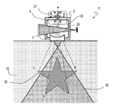
- FIG. 1 is a schematic configuration diagram showing a first embodiment of an acousto-optic imaging device according to the present invention.
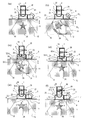
- (A) to (f) is a diagram for explaining the operation of the acousto-optic imaging device shown in FIG. 1, and is a diagram illustrating the time course of ultrasonic waves propagating through the subject and the acousto-optic imaging device. It is a figure which shows the positional relationship of the acoustic image formed in the acousto-optic cell of the acousto-optic imaging device shown in FIG. 1, and the convergent light used for diffraction. It is a figure which shows the experimental result performed in order to confirm the operation
- the inventor of the present application examined a method of acquiring an image two-dimensionally or three-dimensionally, instead of obtaining an image by scanning an ultrasonic wave through a tissue inside a subject like a conventional ultrasonic diagnostic apparatus. .
- the inventors have conceived that an image of a tissue inside a subject is acquired using an acoustooptic effect that is an interaction between ultrasonic waves and light.
- FIG. 9 shows the configuration disclosed in Non-Patent Document 1.
- the monochromatic light beam emitted from the laser light source 1101 is converted into a thick plane wave light beam by the beam expander 1102 and the aperture 1103.
- the plane wave light beam passes through the acousto-optic cell 1108 and the cylindrical lenses 1104 (a), 1104 (b), and 1104 (c), and is projected onto the screen 1105.
- the optical system composed of the cylindrical lenses 1104 (a), 1104 (b), and 1104 (c) has an asymmetric structure in which the convergence state differs between a direction horizontal to the paper surface and a direction perpendicular to the paper surface. For this reason, this optical system has astigmatism.
- the focal length of the cylindrical lens 1104 (a) is such that the plane wave light beam emitted from the beam expander 1102 is focused at the position of the focal plane 1106 on a plane parallel to the paper surface of FIG. Is set.
- the light beam that has passed through the focal plane 1106 diverges after passing through the focal plane 1106.
- the divergent light beam is converged by the cylindrical lens 1104 (b) and refocused on the screen 1105.
- the plane wave light beam that has passed through the beam expander 1102 enters the cylindrical lens 1104 (c) as a parallel light beam. Thereafter, the light is focused on the screen 1105 by the light collecting action of the cylindrical lens 1104 (c).
- the positions and lens surfaces of the cylindrical lenses 1104 (a), 1104 (b), and 1104 (c) are enlarged images in the direction parallel and perpendicular to the paper surface of FIG.
- the ratio (magnification rate size of the object 1109 to be photographed / size of the image on the screen 1105) is set to be equal.
- the object 1109 to be photographed is immersed in an acousto-optic cell 1108 filled with water 1107.
- a to-be-photographed object 1109 is irradiated with monochromatic ultrasonic plane waves generated from an ultrasonic transducer 1111 driven by a signal source 1110 via water 1107.
- an ultrasonic scattered wave is generated in the object to be imaged 1109, and the scattered wave propagates through a passing region in the water 1107 of monochromatic light from the laser light source 1101. Since the main guided mode of ultrasonic waves propagating in water is a dense wave (longitudinal wave), a sound pressure distribution in water 1107, that is, a refractive index distribution that matches the ultrasonic wave front is generated in water.
- the refractive index distribution generated in the water 1107 becomes a sinusoidal one-dimensional grating repeated at the ultrasonic wavelength. . Therefore, diffracted light (only the ⁇ first-order diffracted light beam is expressed in the figure) is generated by the one-dimensional grating.
- the diffracted light appears as a light spot on the screen 1105.
- the brightness of the light spot is proportional to the amount of change in the refractive index of the one-dimensional grating, that is, the ultrasonic sound pressure.
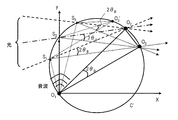
- FIG. 10 schematically shows the acoustooptic effect by Bragg diffraction.
- a point O 1 is a point sound source (Huigens sound source) and radiates a spherical wave.
- the light converges to the point O 2 with the line segment S 1 O 2 and the line segment S 3 O 2 in FIG.
- the density of the acoustic medium caused by ultrasonic, -1-order Bragg diffraction light is generated in a direction that satisfies the Bragg angle theta B at each point on the arc S 1 S 3, it converges to a point O 3.
- the points O 1 , O 2 , O 3 are located on the same circumference C ′.
- the triangle O 1 O 2 O 3 is an isosceles triangle, and the angle O 2 O 1 O 3 is 2 ⁇ B.
- the point sound source O 1 can be generated as an optical image.
- ⁇ is the wavelength of the sound wave
- ⁇ is the wavelength of the light.
- image formation based on such a principle is performed by an optical image forming action of a condensing optical system as in the case of a normal optical camera.
- a receiver group required for a conventional electronic scanning ultrasonic diagnostic apparatus, a probe including a large number of ultrasonic transducers with uniform transmission / reception characteristics, and a reception signal group output from the receiver group The tissue in the subject can be imaged without using a high-speed and large-scale arithmetic circuit for performing signal processing such as beam forming for the.
- Non-Patent Document 1 only discloses the acoustooptic effect by Bragg diffraction, and there is no suggestion how to realize imaging of a tissue in a living body by the acoustooptic effect.
- the frequency of the ultrasonic wave used is as high as 15 MHz or more. This is because the acousto-optic cell is composed of an aqueous medium, and the conditions under which Bragg diffraction occurs are limited by the relationship between the acoustic velocity of water (about 1500 m / s) and the wavelength of ultrasonic waves. .
- Non-Patent Document 1 In a living body, absorption attenuation increases substantially in proportion to the frequency. Therefore, it is preferable to use an ultrasonic wave having a frequency of 10 MHz or less in order to image a deep interior of a subject. Therefore, even if the configuration disclosed in Non-Patent Document 1 is used as it is, it is difficult to obtain an image of the tissue in the body of the subject.
- Non-Patent Document 1 uses scattered waves generated in the vicinity of the contour of the object to be imaged 1109, it is difficult to image a tissue in a living body in detail by such a method.
- Non-Patent Document 1 the range that can be obtained as an image is very narrow, and the distance from the interaction area with light is limited. As shown in FIG. 10, this is because the sound source indicated by the point O 1 , the point O 2 that is the convergence position of the light, and the point O 3 that is the convergence position of the diffracted light are on the same circumference.
- the distance between the light that converges at the point O 2 and the point O 1 that is the sound source increases (in the Z direction in FIG. 10), the arc increases in proportion to the distance. Therefore, in order to image the ultrasonic waves from the deep part of the living body, the acousto-optic cell becomes large.
- a similar problem occurs when the point O 3 as the sound source moves in the horizontal direction (X direction in FIG. 10). As a result, it is difficult to obtain an image over a wide range in the living body.
- the inventor of the present application has studied such a problem in detail and has come up with a novel acousto-optic imaging device.
- the outline of one aspect of the acousto-optic imaging device of the present invention is as follows.
- An acoustooptic imaging device disclosed in the present application includes an ultrasonic transmitter that transmits ultrasonic waves that diverge into a subject, an acoustic lens that converges reflected ultrasonic waves from the ultrasonic waves from the subject, and An acoustooptic cell having an acoustic velocity that is smaller than that of a subject and including an acoustooptic propagation medium portion through which the reflected ultrasound focused by the acoustic lens propagates; and the reflected ultrasound that propagates through the acoustooptic propagation medium portion, A light source that emits convergent light that irradiates in a direction non-parallel to the traveling direction of the reflected ultrasound, and an image that detects Bragg diffracted light of the convergent light generated by the acoustooptic propagation medium unit and converts it into an electrical signal And an optical system.
- the convergent light irradiates a region in the acoustooptic propagation medium portion where the reflected ultrasonic wave propagates in a divergent wave state after convergence.
- the convergent light irradiates a region in the acoustooptic propagation medium portion where the reflected ultrasonic wave propagates in a convergent wave state.
- the acousto-acoustic optical propagation medium includes a perfluorocarbon-based inert liquid.
- the acousto-acoustic-optic propagation medium includes a hydrofluoroether-based inert liquid.
- the acousto-acoustic optical propagation medium includes a silica nanoporous material.
- the acousto-optic imaging device further includes a receiving standoff for supporting the acoustic lens, and a convergence point on the subject side of the acoustic lens is located in the receiving standoff.
- the acousto-optic imaging apparatus further includes a transmission stand-off that supports the ultrasonic transmitter, the ultrasonic transmitter emits a convergent ultrasonic wave, and the convergence point is the transmission stand. Located in off.
- FIG. 1 is a schematic diagram showing a first embodiment of an acousto-optic imaging device of the present invention.
- the acoustooptic imaging device 1 illustrated in FIG. 1 images a tissue inside a subject 12 such as a person or an animal.
- the internal organs of the subject 12 are schematically shown as star-shaped reflectors 26 for easy understanding.
- the reflector 26 is shown as a two-dimensional object parallel to the paper surface, but the reflector 26 is generally a three-dimensional object.
- the ultrasonic wave is reflected at a portion where there is a difference in acoustic impedance, such as an internal organ or tissue, as in a conventional ultrasonic diagnostic apparatus. For this reason, each tissue inside the subject can be imaged as the reflector 26 as in the conventional ultrasonic diagnostic apparatus.
- the acoustooptic imaging device 1 includes an ultrasonic wave transmitter 5, an acoustic lens 3, an acoustooptic cell 2, a light source 13, and an imaging optical system 14.
- the acousto-optic imaging device 1 transmits ultrasonic waves from the ultrasonic transmitter 5 to the subject 12 and receives reflected ultrasonic waves reflected by the subject 12 by the acoustic lens 3.
- the acoustic lens 3 converges the received reflected ultrasonic wave.
- the converged reflected ultrasonic waves propagate through the acousto-optic cell 2.
- the convergent light emitted from the light source 13 irradiates reflected ultrasonic waves that propagate through the acousto-optic cell 2. Thereby, diffraction by reflected ultrasonic waves is generated.
- the imaging optical system 14 obtains an image inside the subject 12 by detecting the generated diffracted light and converting it into an electrical signal.
- each component will be described in detail.
- the ultrasonic transmitter 5 transmits ultrasonic waves to the subject 12.
- the ultrasonic wave transmitted by the ultrasonic wave transmitter 5 is preferably a divergent wave that diverges in the subject. Since the internal tissue of the subject within the transmission range 11 of the ultrasonic wave to be transmitted can be imaged, the wider the inside of the subject can be imaged as the ultrasonic wave to be transmitted diverges widely.
- the ultrasonic wave transmitter 5 transmits an ultrasonic convergent wave from the wave transmitting surface 5a and emits an ultrasonic wave diverging from a convergence point 5b at a predetermined distance from the wave transmitting surface 5a inside the subject 12.
- the acoustooptic imaging device 1 further includes a transmission standoff 7.
- the transmission stand-off 7 supports the ultrasonic transmitter 5 so that the convergence point 5 b is located within the transmission stand-off 7. This prevents the ultrasound from converging and positioning the convergence point 5b where the energy density is high inside the subject.
- the subject 12 can be irradiated with ultrasonic waves in a divergent state on the surface 12a of the subject 12, an image can be acquired in a wide range even in the vicinity of the surface 12a in the subject 12.
- the transmission standoff 7 has a deaerated water with various attenuations of the transmitted ultrasonic wave and various types. Filled with a coupling medium 8 such as oil.
- the ultrasonic wave transmitter 5 transmits an ultrasonic convergent wave from the wave transmitting surface 5a, but may transmit an ultrasonic divergent wave directly from the wave transmitting surface 5a. In this case, the transmission standoff 7 need not be used.
- the ultrasonic wave transmitted by the ultrasonic transmitter 5 is, for example, a burst wave.
- the burst wave has a time waveform in which a sine waveform or a rectangular waveform having a constant amplitude and frequency, such as a plurality of the same sine waveforms, continues for a fixed time.
- the burst wave preferably has such a wave number as to cause Bragg diffraction.
- the wave number is preferably about 3, 4 to 20 waves.
- the ultrasonic wave to be transmitted preferably has a frequency with little attenuation inside the subject 12 to be imaged, and preferably has a frequency of several MHz to 15 MHz.
- the repetition timing can be arbitrarily set.
- the repetition timing is, for example, several Hz to several KHz. It's okay.
- the ultrasonic wave transmitted by the ultrasonic transmitter 5 is transmitted to the subject 12 through the window 9 in contact with the subject 12.
- it is applied to the surface 12a of the subject 12 or the surface of the probe in a conventional ultrasonic diagnostic apparatus.
- a matching gel or cream may be placed between the window 9 and the subject 12.
- An acoustic impedance matching layer may be used. These matching gel, cream, and acoustic impedance matching layer may be used to efficiently guide the reflected ultrasonic wave obtained from the subject 12 to the acoustic lens 3 through the window 9.
- the acoustic lens 3 receives and converges the reflected ultrasonic wave generated when the ultrasonic wave transmitted from the ultrasonic wave transmitter is reflected inside the subject 12.
- the acoustic lens 3 is of a refractive type and has a rotationally symmetric shape with the sound axis 3a as an axis. Therefore, the reflected ultrasonic waves are converged three-dimensionally (in the x, y, and z directions) based on the shape of the acoustic lens 3 in accordance with Snell's law.
- the acoustic lens 3 has focal points F and F ′ on the subject 12 side and the acousto-optic cell 2 side, for example.
- the surface of the acoustic lens 3 on the subject 12 side has a convex shape toward the outside direction. Thereby, the reflected ultrasonic wave incident from the subject 12 side can be converged.
- the speed of sound in the acoustic lens is higher than the speed of sound in the subject 12, the surface of the acoustic lens 3 on the subject 12 side has a concave shape toward the external direction.
- the acoustic lens 3 is preferably held with respect to the subject 12 so that the convergence point (focus) on the subject 12 side is located outside the subject 12. Thereby, the reflected ultrasonic wave obtained from the region in the vicinity of the surface 12a in the subject 12 can be converged to the convergence point on the opposite side of the acoustic lens 3 from the subject 12.
- the acousto-optic imaging device 1 further includes a wave receiving standoff 33 that supports the acoustic lens 3 so that the convergence point of the acoustic lens 3 on the subject 12 side is located in the wave receiving standoff 33. It may be. Thereby, the above-described arrangement relationship between the acoustic lens 3 and the subject 12 can be realized.
- the convergence point of the acoustic lens 3 on the subject 12 side is the subject. It may be located inside the specimen 12.
- the acoustic lens is composed of an elastic body with a small acoustic wave propagation loss, such as a silica nanoporous material, water, a fluorine-based inert liquid such as fluorinate, or polystyrene.
- the wave receiving stand-off 33 is filled with a coupling medium 6 such as deaerated water or various oils with little attenuation of transmitted ultrasonic waves.
- the acoustooptic cell 2 includes an acoustooptic propagation medium section 24.
- the acousto-optic propagation medium unit 24 has a sound velocity smaller than that of the subject 12 and is disposed with respect to the acoustic lens 3 so that the reflected ultrasonic wave converged by the acoustic lens 3 propagates.
- the acoustooptic propagation medium portion 24 is disposed at a position including the sound axis 3a.
- the acoustooptic propagation medium section 24 is made of a liquid or isotropic elastic body that has little propagation attenuation of the reflected ultrasonic wave that propagates and has translucency with respect to the convergent light 29 emitted from the light source 13.
- the acoustooptic propagation medium 24 is made of, for example, a fluorine-based solvent such as silica nanoporous material or fluorinate. Since the sound velocity of the acoustooptic propagation medium unit 24 is lower than the sound velocity of the subject 12, the wavelength of the ultrasonic wave propagating through the acoustooptic propagation medium unit 24 is shortened, and the Bragg diffracted light is generated even if the frequency is low. Can do.
- the light source 13 emits convergent light 29 that irradiates the reflected ultrasonic wave propagating through the acoustooptic propagation medium unit 24 in a direction non-parallel to the traveling direction of the reflected ultrasonic wave.
- the light source 13 includes, for example, a monochromatic light source 15, a beam expander 16, a reflection mirror 17, and a cylindrical lens 18.
- the monochromatic light source 15 generates a light beam 28 having high coherence.
- the light in the light beam 28 has the same wavelength and phase.
- a gas laser represented by a He—Ne laser, a solid-state laser, a semiconductor laser narrowed by an external resonator, or the like can be used as the monochromatic light source 15 for example.
- the light beam emitted from the monochromatic light source 15 may be continuous, or may be a pulsed light beam whose emission time can be controlled.
- the aperture of the light beam emitted from the monochromatic light source 15 is increased by the beam expander 16, reflected by the reflection mirror 17, and then converted into convergent light by the cylindrical lens 18.
- the cylindrical lens 18 has a lens shape for converging light on a plane parallel to the paper in FIG. 1, and has a columnar shape extending in a direction (z direction) perpendicular to the paper surface. For this reason, the light transmitted through the beam expander 16 is converged in a direction parallel to the paper surface (xy plane) and not converged in the z direction.
- the convergent light 29 emitted from the light source 13 irradiates reflected ultrasonic waves on the opposite side of the acoustic lens 3 with respect to the convergence point of the acoustic lens 3 in the acoustooptic propagation medium unit 24.
- the convergent light 29 irradiates the acoustooptic propagation medium 24 in the traveling direction of the reflected ultrasonic wave, that is, in a direction non-parallel to the sound axis 3 a of the acoustic lens 3.
- the imaging optical system 14 detects the Bragg diffracted light of the convergent light generated by the acoustooptic propagation medium unit 24, converts the diffracted light into an electrical signal, and outputs it.
- the imaging optical system 14 includes, for example, a cylindrical lens 21, a mirror 20, a cylindrical lens 19, and an image sensor 22.
- a shielding plate 23 that shields the convergent light 29 may be provided.
- the focal length of the cylindrical lens 21 is set so that the diffracted light reflected by the mirror 20 is focused on the light receiving surface of the image sensor 22 on a plane parallel to the paper surface of FIG.
- the focal length of the cylindrical lens 19 is set so as to focus on the light receiving surface of the image sensor 22 on a plane parallel to the paper surface of FIG.
- Image processing is performed on the output from the imaging optical system 14 as necessary, and an image of the internal tissue of the subject 12 is displayed by being input to the display device.
- FIG. 2A shows the state of the acousto-optic imaging device 1 before the ultrasonic transmitter 5 transmits ultrasonic waves. Bragg diffracted light 30 is not generated in the acousto-optic cell 2.
- FIG. 2B shows a time change of the ultrasonic wave 31 transmitted from the ultrasonic wave transmitter 5.
- the ultrasonic waves transmitted from the ultrasonic wave transmitter 5 propagate in the acoustic medium portion with the passage of time in the order of ultrasonic waves 31 0 , 31 1 , 31 2 .
- the reflected ultrasonic waves generated at the same time are omitted.
- the ultrasonic waves 31 0 , 31 1 , and 31 2 indicate the ultrasonic waves 31 by the same burst wave at different times and do not exist at the same time.
- FIG. 2C shows a state in which the ultrasonic wave 31 is reflected by the reflector 26 when passing through the reflector 26 in the subject 12 to generate a reflected wave.
- the ultrasonic wave 31 When the ultrasonic wave 31 reaches the reflector 26 in the subject 12, the ultrasonic wave 31 is reflected at each point constituting the reflector 26, and a reflected ultrasonic wave is generated.
- This reflected ultrasonic wave is a diverging spherical wave having each point as a point source.
- FIG. 2C when the ultrasonic wave 31 passes through the reflector 26, a part of the ultrasonic wave 31 is reflected at the vertices A, B, and C, and the reflected ultrasonic waves 32-A, 32-B, and 32-C are generated. It shows how to do.
- the ultrasonic waves 31 are reflected at portions other than the vertices A, B, and C of the reflector 26, the reflection at other portions is not shown for the sake of easy understanding.
- the reflected ultrasonic waves 32-A, 32-B, and 32-C are spherical waves as described above, and propagate from the vertices A, B, and C in all directions. Only shows.
- the component toward the acoustic lens 3 propagates along a line segment connecting the curvature center G of the acoustic lens from each of the vertices A, B, and C.
- the reflected ultrasonic wave 32-A reflected by the vertex A propagates toward the acoustic lens 3 earliest.
- the reflected ultrasonic wave 32-B from the vertex B where the ultrasonic wave 31 reaches earlier than the vertex C propagates.
- the reflected ultrasonic wave 32-C from the vertex C propagates toward the acoustic lens 3.
- the reflected ultrasonic wave 32-C has a smaller propagation range than the reflected ultrasonic waves 32-A and 32-B. This expresses that the reflected ultrasonic wave 32 diverges as it propagates.
- the reflected ultrasonic waves 32-A, 32-B, and 32-C propagate from the positions of the vertices A, B, and C of the reflector 26.
- the order in which the reflected ultrasonic waves 32-A, 32-B, and 32-C reach the acoustic lens 3 is determined based on the distance between the ultrasonic transmitter 5 and the vertices A, B, and C of the reflector 26 and the vertices A, It depends on the distance between B and C and the acoustic lens 3.
- the reflected ultrasonic waves 32-A, 32-B, and 32-C are spherical waves, they diverge as they propagate toward the acoustic lens 3. For this reason, the reflected ultrasonic wave 32-C showing immediately after being reflected from the point C is shown small.
- FIG. 2D shows the reflected ultrasonic waves 32-A, 32-B, and 32-C that have elapsed from the state shown in FIG.
- the reflected ultrasonic wave 32-A is transmitted through the acoustic lens 3 and propagates through the acoustooptic propagation medium portion 24 in the acoustooptic cell 2.
- the reflected ultrasonic wave 32-B propagates inside the acoustic lens 3.
- the reflected ultrasonic wave 32-C propagates in the receiving standoff 33.
- the reflected ultrasonic wave 32 that has entered from the acoustic lens 3 converges three-dimensionally toward the convergence point of the acoustic lens 3 due to the lens effect of the acoustic lens 3. This corresponds to the imaging process of the acoustic image formation of the reflector 26.
- the formation of an acoustic image means that ultrasonic waves converge due to the acoustic lens effect, and the sound waves concentrate at the convergence point.
- the ultrasonic waves that converge toward the convergence point then diverge.
- the process from the formation of the image at the convergence point to the process in which the ultrasonic waves diverge is defined as an “imaging process”.
- the thickness of the wave packet is thin because the acoustic lens 3 has a lower sound velocity than the subject 12.
- the reflected ultrasonic waves 32-A and 32-B have a convex shape on the acoustic lens 3 side in FIG. 2 (c), whereas in FIG. 2 (d), the reflected ultrasonic waves 32-A, 32-B has a convex shape on the subject 12 side. This is because the waveform converges in a plane perpendicular to the traveling direction of the ultrasonic waves 32-A and 32-B due to the lens effect of the acoustic lens 3, that is, the convergence action.
- the reflected ultrasonic waves 32-A, 32-B, and 32-C reach the acoustic lens 3 depending on the distance between the vertices A, B, and C that are reflection positions and the acoustic lens 3.
- the degree of divergence is different.
- the point of convergence of the reflected ultrasonic waves 32-A, 32-B, and 32-C by the acoustic lens 3 is not one, but differs depending on the reflected ultrasonic waves 32-A, 32-B, and 32-C.
- the reflected ultrasonic wave from the inside of the subject 12 converges three-dimensionally in the acoustic imaging portion 4 to form an image.
- the acoustic imaging portion 4 is located farther from the subject 12 than the convergence point at which the plane acoustic wave converges when the plane acoustic wave enters the acoustic lens 3.
- the image referred to here is a sound pressure distribution that reflects the shape of the reflector 26 in the acoustooptic propagation medium portion 24 and that has the highest sound pressure. Hereinafter, it is also called an acoustic image.
- an image by reflected ultrasound can be acquired in the subject 12 because the ultrasound transmitted from the ultrasound transmitter 5 can diverge.
- the transmission range 11 is determined by the degree of divergence of the ultrasonic wave transmitted from the ultrasonic transmitter 5.
- the receiving range 10 is determined by the characteristics of the acoustic lens 3.
- FIG. 2E shows the reflected ultrasonic waves 32-A, 32-B, and 32-C that have elapsed from the state shown in FIG.
- the reflected ultrasonic wave 32-A converges most when passing through the acoustic imaging portion 4, and then propagates through the acoustooptic propagation medium portion 24 while diverging again.
- the reflected ultrasonic wave 32-B is located in the acoustic imaging portion 4 and is in the most converged state. That is, the reflected ultrasonic wave 32-B exists as a point corresponding to the vertex B.
- the reflected ultrasonic wave 32-C reaches the acoustic imaging portion 4 of the acoustooptic propagation medium portion 24. Until this time, the reflected ultrasonic waves 32-A, 32-B, and 32-C have not reached the region irradiated with the convergent light 29 of the acoustooptic propagation medium unit 24. For this reason, the Bragg diffracted light 30 is not generated yet.
- FIG. 2 (f) shows reflected ultrasonic waves 32-A, 32-B, and 32-C that have passed the time from the state shown in FIG. 2 (e).
- the reflected ultrasonic wave 32-A reaches the convergent light 29 that passes through the acoustooptic propagation medium 24.
- the reflected ultrasonic wave 32-B also reaches the convergent light 29 that passes through the acoustooptic propagation medium 24 in a divergent state.
- the reflected ultrasonic wave 32-C is located in the acoustic imaging portion 4 and is in the most converged state.
- the Bragg diffracted light 30 is generated by the reflected ultrasonic waves 32-A and 32-B, respectively.
- the generated Bragg diffracted light 30 is detected by the imaging optical system 14. Since the focal point of the cylindrical lens 21 is located on the light receiving surface of the image sensor 22, optical images of points A and B are formed on the light receiving surface. The image sensor 22 detects an optical image and converts it into an electrical signal.
- the reflected ultrasonic wave 32-C then diverges and reaches the convergent light 29 that passes through the acoustooptic propagation medium 24. Thereby, the Bragg diffracted light 30 is generated, and the image sensor 22 detects the optical image at the point C.
- FIG. 3 shows a positional relationship between the acoustic image formed by the acoustic lens 3 in the acoustic imaging portion 4 of the acousto-optic propagation medium unit 24 and the convergent light 29.
- the reception standoff 33 and the coupling medium 6 have a sound speed substantially the same as the sound speed of the subject 12.
- a point G shown in FIG. 3 indicates the center of curvature of the acoustic lens 3. In the first embodiment, it is hemispherical.
- the range 35 shown in FIG. 3 schematically shows the convergence characteristics of the acoustic lens 3 in the hemispherical shape.
- a point F shown in FIG. 3 indicates a convergence point (focal point) on the hemispherical shape side.
- a point sound source is arranged at the point F, a plane wave is observed on a plane perpendicular to the sound axis 3 a and passing through the center of curvature G of the acoustic lens 3.
- the inside of the subject 12 is scanned by converging ultrasonic waves transmitted from a large number of ultrasonic transducers of the probe into a beam shape. At this time, an image can be acquired with higher resolution as the beam diameter is smaller.
- the acoustic lens 3 does not improve the resolution near the point F, but the center of curvature of the acoustic image 27 of the reflector 26 in the subject 12. It is to be formed in the acoustic imaging portion 4 set farther than G.
- the reflector 26 In order for the acoustic image to be formed on the acoustic imaging portion 4, the reflector 26 needs to be positioned on the opposite side of the acoustic lens 3 from the point F. In the optical lens, a sound source positioned closer to the acoustic lens 3 than the point F cannot be converged by the acoustic lens 3 in the same manner that an object positioned closer to the optical lens than the focal point cannot form a real image. Because.
- the acoustic image 27 formed on the acoustic imaging portion 4 is a three-dimensional image determined by the shape of the reflector 26 and the relative position with the acoustic lens 3 (in the figure, the reflector 26 is shown as a two-dimensional image). .
- the acoustic lens 3 in the acousto-optic imaging device 1 is used with a completely different function from conventional ultrasound, and the acoustic image 27 becomes a secondary sound source, and divergent ultrasound is regenerated in the acousto-optic propagation medium unit 24.
- the acousto-optic imaging of the reflector 26 based on the principle of Bragg diffraction shown in FIG. 10 is performed. Therefore, the position where the acoustooptic effect occurs, that is, the position of the convergent light 29 is arranged farther from the acoustic lens than the acoustic imaging portion 4.
- the principle of Bragg diffraction is established on an xy plane at an arbitrary z-axis position in FIG. 3, that is, an arbitrary xy plane. Therefore, the acoustic image 27 is imaged by the principle of Bragg diffraction on a plane parallel to the paper surface of FIG.
- the acoustic lens 3 has a prospective angle ⁇ sufficient to image the reflector 26 in a wide range, and the vertices A, B, C, D, and E of the reflector 26 are larger than the points. Located far away. Accordingly, the acoustic image 27 is reversed left and right on an extension line connecting each vertex and the center of curvature G, and the acoustic image 27 is represented as points A ′, B ′, C ′, D ′, and E ′ in the acoustic imaging portion 4. Form. As described with reference to FIGS. 2A to 2F, the acoustic image 27 is not formed at the same time.
- the points A ′, B ′, C ′, D ′, and E ′ are in order according to the propagation time of the ultrasonic wave obtained from the distance between the ultrasonic transmitter 5 and the reflector 26 and the distance between the reflector 26 and the acoustic lens 3.
- the image sensor 22 also detects the acoustic image 27 (that is, the reflector 26) in an order that matches the formation order of the acoustic image 27.
- the acoustic image 27 is distorted in shape due to the influence of the response function of the acoustic lens 3, and these can be analyzed at the design stage. Accordingly, after the image is acquired by the image sensor 22, the image data may be corrected based on the analysis result.
- FIG. 4 shows a beam pattern of sound waves from a point sound source formed by an acoustic lens.
- ten point sound sources 41 are arranged at star-shaped vertices and root positions.
- the point sound source 41 has directivity in the direction of the curvature center G and in the opposite direction on a straight line connecting each point and the curvature center G of the acoustic lens. Accordingly, in FIG. 4, each point sound source 41 appears as two sound sources.
- the subject 12 is made of water, has a density of 1 g / cc, and a sound speed of 1500 m / s.
- the speed of sound of the acoustic lens 3 and the acoustic imaging portion 4 is 500 m / s, and the density is 1.6 g / cc.
- the acoustic lens 3 is covered with a thin cover layer 25 (polyethylene, sound velocity 1950 m / s, density 0.9 g / cc, thickness 0.4 mm).
- the radius of curvature of the acoustic lens is 15 mm, and the point sound source 41 is disposed in the range of 10 mm to 36 mm from the tip of the acoustic lens 3.
- the spread in the y direction is about 27 mm.
- FIG. 4 shows that each point sound source 41 has a frequency of 5 MHz and burst ultrasonic waves of 10 periods are simultaneously emitted to form an image in the acoustic imaging portion 4 in the acousto-optic cell 2 via the acoustic lens 3. After that, the time until divergence is calculated, and the maximum value of the sound pressure within the calculation time at each point in the calculation space is shown.
- each beam converges to form an acoustic image, and then diverges.
- FIG. 5 shows the instantaneous sound pressure distribution at the time when the acoustic image is formed in the acoustic imaging portion 4.
- a convergence point (image formation) 51 of a sound wave is shown. Since the structure of the acoustic lens 3 is a simple spherical structure and the sound waves are simultaneously emitted from the sound sources, it can be observed that the sound waves from the sound sources are converged and imaged almost simultaneously. However, the sound source closest to the acoustic lens did not converge and then propagated as a plane wave. Under the simulation conditions, the focal length of the acoustic lens is around 10 mm, and the point sound source is arranged near the focal point.
- the acoustic image of the other sound source diverges after the time shown in FIG. 5 and propagates in the acoustooptic cell 2 as a spherical wave. Therefore, these point sound sources can be optically photographed using a light source and an imaging optical system.
- the minimum imaging distance was about 10 mm in the configuration according to this simulation. Therefore, when an internal image is desired to be acquired from directly below the surface of the subject 12, the acoustic lens 3 may be separated from the surface of the subject 12 by 10 mm or more by a receiving standoff.
- the acoustic velocity 500 m / s and the density 1.6 g / cc were set as the acoustooptic propagation medium portion 24 of the acoustooptic cell 2.
- This physical property can be realized by using, for example, 3M Fluorinert FC IV-72.
- Fluorinate is an inert liquid in which several kinds of perfluorocarbons are mixed and has a very low reactivity with other substances, and is therefore suitable as a constituent material for the acoustooptic propagation medium 24 and the acoustic lens 3.
- the wavelength compression effect is about three times, so that the Bragg diffraction condition can be satisfied by imaging the subject 12 using ultrasonic waves of 5 MHz or more, preferably about 10 MHz. Therefore, the reflector distribution inside the subject can be imaged by Bragg diffraction.
- Novec 7100 and Novec 7200 are inert liquids mainly composed of hydrofluoroether.
- the speed of sound is about 630 m / s, and the density is around 1.5 g / cc.
- Fluorinert the sound speed is slightly higher and the wavelength compression effect is lower, but if an ultrasonic wave of about 10 MHz is used, the conditions of Bragg diffraction can be sufficiently satisfied.
- a nanofoam material that is a porous silica material can be used as another material that can be used for the acoustooptic propagation medium 24 .
- the density of the nanofoam material is 0.05 g / cc to 0.3 g / cc, has a sufficient light transmittance, and the sound velocity is about 50 m / s to 300 m / s.
- the solid acoustic material is extremely suitable as a low acoustic velocity material for acousto-optic cells because of its extremely low acoustic velocity.
- the acoustic impedance of the porous silica material is significantly different from that of a living body, it is preferable to use an acoustic matching structure.
- the wavelength of the sound wave at 10 MHz is 5 ⁇ m. If a near-infrared laser beam with a wavelength of 1.5 ⁇ m is used as the light source, the Bragg diffraction angle is about 8 degrees.
- the black angle in Non-Patent Document 1 is about 0.3 degrees, and the separation distance from the zero-order light can be significantly shortened by increasing the diffraction angle. Since most of the dimensions of the imaging optical system are the distances for separating the 0th-order light and the diffracted light, the introduction of the nanoform acousto-optic cell can realize a significant downsizing of the imaging optical system.
- the acoustic lens 3, the acoustooptic propagation medium unit 24, and the acoustic imaging portion 4 may be made of the same material or different materials. Even if each part is made of a different material, it is sufficient that the acoustic pressure and the wavelength compression effect at which Bragg diffraction occurs in the acoustooptic propagation medium part 24 can be ensured. Further, when the acoustic lens 3 is made of a liquid material such as Fluorinert or Novec, it is preferable to provide the cover layer 25 on the surface of the acoustic lens 3. As a material for the cover layer, a plastic material such as polyethylene or polystyrene is suitable.
- the acoustic lens 3 has a hemispherical shape, a dome shape or an aspherical shape smaller than the hemisphere may be used as long as a predetermined receiving range is ensured and an acoustic image is formed. It may be a solid lens made of a material or the like.
- the coupling medium 8 in the transmission stand-off 7 and the coupling medium 6 in the reception stand-off 33 deaerated water, various oils, or the like may be used. From the viewpoint of acoustic compatibility with the living body and the coupling medium, industrial plastics such as polystyrene, PET, and PPS can be suitably used for the window 9.
- the diverging ultrasonic waves are transmitted toward the inside of the subject, the reflected ultrasonic waves obtained from the inside are converged by the acoustic lens, and the acousto-optics are diverged after the convergence. Propagate through the propagation medium.
- the reflected ultrasonic wave propagating through the acousto-optic propagation medium part in a divergent wave state with the convergent light diffracted light by Bragg diffraction can be obtained. Therefore, an image inside the subject can be optically acquired at high speed without performing complicated ultrasonic signal processing.
- the wavelength of the ultrasonic wave propagating through the acoustooptic propagation medium portion is shorter than the ultrasonic wave propagating through the subject.
- the frequency of ultrasonic waves transmitted from the transmitter can be lowered, and very low frequency ultrasonic waves that are difficult to attenuate inside the subject can be used.
- FIG. 6 is a schematic diagram showing the main part of a second embodiment of the acousto-optic imaging device of the present invention.
- the acousto-optic imaging device 1 ′ of the present embodiment is different from the first embodiment in the position at which the reflected light propagating through the convergent light 29 and the acousto-optic propagation medium unit 24 acts. Since the configurations of the ultrasonic transmitter 5, the light source 13, and the imaging optical system 14 are the same as those in the first embodiment, they are not shown in FIG.
- the acousto-optic imaging device 1 ′ includes a resin acoustic lens 3 having concave surfaces on both sides.
- the convergent light 29 is transmitted through the acoustooptic propagation medium portion 24 between the acoustic imaging portion 4 and the acoustic lens 3.
- the reflected ultrasound waves converged light 29 is transmitted through the area to be propagated in a state in which a converging wave, to produce a Bragg diffraction light.
- the acoustic wave converges to the point O 1 , and the point O 1 can be regarded as the convergence point of the convergent sound wave. Therefore, there is no geometric change except that the ultrasonic wave propagation direction is opposite in the ultrasonic wave and light interaction region (points S 1 to S 3 ) and the ultrasonic wave is in a convergent wave state. Similarly, Bragg diffraction of light by ultrasonic waves also occurs, and a diffraction image is formed at the point O 3 .
- the diffracted light generated here is + 1st order light and the diffraction image is a + 1st order diffraction image, there is no substantial difference between the + 1st order diffraction image and the ⁇ 1st order diffraction image. Therefore, in the configuration shown in FIG. 6 as well, the inside of the subject 12 can be imaged as in the first embodiment.
- the acoustic lens 3 is a biconcave acoustic lens, the width of the recess (lens opening width) is 20 mm on both sides, and the radius of curvature on the subject 12 side is 52 mm. The curvature radius on the acousto-optic cell side is 14.8 mm.
- the lens has a thickness of 10 mm and is made of polystyrene (density 1.05 g / cc, longitudinal wave sound velocity 2400 m / s, shear wave sound velocity 1050 m / s).
- the acoustooptic propagation medium section 24 of the acoustooptic cell 2 is a high-performance liquid Novec 7200 (density 1.43 g / cc, sound velocity 623 m / s) manufactured by 3M, and the width of the acoustooptic propagation medium section 24 (y direction in the figure). ) Is 26 mm, and the ultrasonic propagation direction dimension (x direction in the figure) is 24 mm.
- the focal length in the Novec 7200 is 15 mm.
- the medium on the subject side was water (density 1 g / cc, sound speed 1496 m / s).
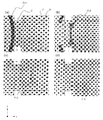
- FIG. 7 (a) to 7 (d) show the image formation of the ultrasonic wave 71 when it is arranged on a point sound source (point reflector) at a distance of 60 mm from the acoustic lens and at an angle of 0 degree. Ten cycles of burst transmission were used at a frequency of 5 MHz.
- FIG. 7A shows a sound pressure distribution at a time immediately before the ultrasonic wave 71-1 from the sound source enters the acoustic lens. The ultrasonic wave 71-1 diverges in a convex shape in the propagation direction.
- FIG. 7B shows a state in which a part of the ultrasonic wave 71-2 incident on the acoustic lens 3 is transmitted to the acoustooptic propagation medium unit 24.
- FIG. 7 (c) shows a state in which the entire wave packet of ultrasonic 71-3 is transmitted through the acousto-optic propagation medium portion 24, and propagates.
- the wave packet is compressed in the propagation direction by the wavelength compression effect of the acousto-optic propagation medium section 24. Further, due to the lens effect of the acoustic lens 3, it is concave with respect to the propagation direction, and the ultrasonic waves are in a convergent state.
- the convergent light 29 may be arranged near the ultrasonic wave 71-3 shown in FIG.
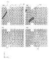
- FIG. 8 shows the result of calculation under the same conditions as the simulation shown in FIG. 7 with the point sound source arranged at a distance of 60 mm and an angle of +30 degrees (upper left direction in the figure).
- FIG. 8A shows a state immediately before the ultrasonic wave 71-5 enters the acoustic lens 3.
- FIG. The propagation direction of the ultrasonic wave 71-5 is inclined corresponding to the position of the sound source, but is convex and diverges with respect to the propagation direction.
- the sound wave on the upper side in the drawing from the aperture of the acoustic lens 3 is ignored.
- FIG. 8B shows a state in which most of the ultrasonic waves 71-6 enter the acoustic lens 3 and a part of the ultrasonic waves 71-6 are transmitted through the acoustooptic propagation medium unit 24. Since the ultrasonic waves are incident obliquely, the sound pressure is reduced.
- FIG. 8C shows a state in which the ultrasonic wave 71-7 is completely transmitted through the acoustooptic propagation medium portion 24 and propagates through the acoustooptic propagation medium portion 24. The wavefront is concave with respect to the propagation direction, and the ultrasonic wave is observed in addition to the ultrasonic wave 71-7 in a converged state.
- FIG. 8D shows a state in which the ultrasonic waves 71-8 are sufficiently converged to form an acoustic image.
- the distance from the acoustic lens 3 is about 13 mm.
- the convergent light 29 is arranged around 10 mm from the acoustic lens, the inside of the subject can be imaged to a depth of about 60 mm in an orientation of about ⁇ 30 degrees.
- the converging light is transmitted between the acoustic imaging portion 4 of the acoustooptic propagation medium portion 24 and the acoustic lens 3, so that the acoustooptic cell 2 is smaller than the first embodiment.
- the acoustic imaging portion 4 since the acoustic imaging portion 4 is not used, the acoustic imaging portion 4 may not be provided inside the acoustooptic cell 2.
- a sound absorbing structure such as a sound absorbing material or a wedge is arranged at an appropriate position in the acoustooptic cell 2, and multiple reflection is performed. Unnecessary waves due to may be suppressed.
- a standoff may be provided, and the acoustic lens may be separated from the subject. Thereby, a shallower region of the subject can be imaged.
- the acoustooptic propagation medium section 24 provided in the acoustooptic cell 2 generally has a larger sound wave attenuation characteristic than water.
- Fluorinert FC-72 exhibits an attenuation characteristic of approximately 0.5 dB / mm at 10 MHz
- Novec 7200 also exhibits an attenuation characteristic of approximately 0.2 dB / mm at 10 MHz.
- Nanofoam material which is a solid material, exhibits damping characteristics of 1 dB to 3 dB / mm.
- the attenuation of the reflected ultrasonic wave in the acoustooptic propagation medium unit 24 can be a problem.
- the distance that the reflected ultrasonic wave propagates through the acoustooptic propagation medium unit 24 can be shortened, the influence of attenuation is suppressed, and a wide range image inside the subject is acquired under favorable conditions. can do.
- the acousto-optic imaging device disclosed in the present application is suitably used for a medical ultrasonic diagnostic apparatus.
- it enables significantly faster imaging than conventional ultrasonic diagnostic apparatus is particularly useful in fields such as functional diagnosis of dynamic organs such as the heart. It is also useful as a nondestructive inspection device.
Abstract
Description
図1は、本発明の音響光学撮像装置の第1の実施形態を示す概略図である。図1に示す音響光学撮像装置1は、例えば、人や動物などの被検体12の内部の組織を画像化する。また、被検体12の内部の臓器を、分かりやすさのため模式的に星形の反射体26で示している。以下の図では、反射体26は、紙面と平行な2次元の物体として示しているが、 反射体26は一般に3次元の物体である。実際の人や動物を観察する場合、従来の超音波診断装置と同様、体内の臓器や組織等、音響インピーダンスに差異がある部分で超音波が反射する。このため、従来の超音波診断装置と同様、被検体の内部の各組織が反射体26として画像化され得る。 (First embodiment)
FIG. 1 is a schematic diagram showing a first embodiment of an acousto-optic imaging device of the present invention. The
超音波送波器5は、被検体12へ超音波を送信する。超音波送波器5が送信する超音波は、被検体内において発散する発散波であることが好ましい。送信する超音波の送波範囲11内にある被検体の内部組織を画像化することできるため、送信する超音波が広く発散するほど、被検体内部を広く撮影することができる。 <
The
音響レンズ3は、超音波送波器から送信された超音波が被検体12内部において反射することによって生成する反射超音波を受波し、収束させる。音響レンズ3は、本実施形態では、屈折型であり、音軸3aを軸とする回転対称の形状を有する。このため、スネルの法則に従って、音響レンズ3の形状に基づき、3次元的に(x、y、z方向に)反射超音波を収束させる。音響レンズ3は、例えば、被検体12側および音響光学セル2側において焦点FおよびF’を有する。本実施形態では、音響レンズにおける音速の方が被検体12における音速よりも小さいため、音響レンズ3の被検体12側の面が、その外部方向に向かって、凸形状を有している。これにより、被検体12側から入射する反射超音波を収束させることができる。音響レンズにおける音速の方が被検体12における音速より大きい場合、音響レンズ3の被検体12側の面は、その外部方向に向かって、凹形状を有する。 <
The
音響光学セル2は音響光学伝搬媒質部24を含む。音響光学伝搬媒質部24は、被検体12よりも小さい音速を有し、音響レンズ3によって収束した反射超音波が伝搬するように、音響レンズ3に対して配置される。図1に示すように、音響レンズ3の音軸3aに沿って反射超音波が伝搬するため、音響光学伝搬媒質部24は、音軸3aを含む位置に配置されていることが好ましい。 <Acousto-
The
光源13は、音響光学伝搬媒質部24を伝搬する反射超音波を、反射超音波の進行方向と非平行な方向に照射する収束光29を出射する。このために、光源13は、例えば、単色光源15と、ビームエクスパンダー16と、反射ミラー17と、円筒レンズ18とを含む。 <
The
結像光学系14は、音響光学伝搬媒質部24で生成する収束光のブラッグ回折光を検出し、回折光を電気信号に変換して出力する。結像光学系14は、例えば、円筒レンズ21、ミラー20、円筒レンズ19、イメージセンサ22を備える。回折しない収束光29によって結像光学系14内で迷光等が発生し得る場合には、収束光29を遮蔽する遮蔽板23を設けてもよい。 <Imaging
The imaging
図1および図2(a)から(f)を参照しながら、音響光学撮像装置1の動作を説明する。図2(a)から(f)において、分かりやすさのため、説明に直接関連していない構成要素は図示していない。 <Operation of
The operation of the acousto-
図2(a)は、超音波送波器5が超音波を送信する前の音響光学撮像装置1の状態を示す。音響光学セル2内では、ブラッグ回折光30は発生していない。 <Fig. 2 (a)>
FIG. 2A shows the state of the acousto-
図2(b)は、超音波送波器5から送波された超音波31の時間変化を示す。超音波送波器5から送波された超音波は、超音波310、311、312の順序で、時間の経過とともに音響媒質部伝搬する。説明の都合上、同時に発生する反射超音波は省略している。超音波送波器5から送波された超音波310は、収束点5bでいったん収束した後、発散している。このため、被検体12の内部へ進むにつれて超音波311、312は広がって伝搬する。上述したように、超音波310、311、312は異なる時間における同じバースト波による超音波31を示しており、同時に存在するわけではない。 <Fig. 2 (b)>
FIG. 2B shows a time change of the
図2(c)は、超音波31が、被検体12内の反射体26を通過する際に反射体26で反射し、反射波を生成する様子を示している。 <FIG. 2 (c)>
FIG. 2C shows a state in which the
図2(d)は、図2(c)に示す状態から時間が経過した反射超音波32-A、32-B、32-Cを示している。 <FIG. 2 (d)>
FIG. 2D shows the reflected ultrasonic waves 32-A, 32-B, and 32-C that have elapsed from the state shown in FIG.
図2(e)は、図2(d)に示す状態から時間が経過した反射超音波32-A、32-B、32-Cを示している。 <Fig. 2 (e)>
FIG. 2E shows the reflected ultrasonic waves 32-A, 32-B, and 32-C that have elapsed from the state shown in FIG.
図2(f)は、図2(e)に示す状態から時間が経過した反射超音波32-A、32-B、32-Cを示している。 <FIG. 2 (f)>
FIG. 2 (f) shows reflected ultrasonic waves 32-A, 32-B, and 32-C that have passed the time from the state shown in FIG. 2 (e).
図6は、本発明の音響光学撮像装置の第2の実施形態の主要部を示す概略図である。本実施形態の音響光学撮像装置1’は、収束光29と音響光学伝搬媒質部24を伝搬する反射波が作用する位置が第1の実施形態と異なっている。超音波送波器5、光源13、結像光学系14の構成は第1の実施形態と同じであるため図6には示していない。 (Second Embodiment)
FIG. 6 is a schematic diagram showing the main part of a second embodiment of the acousto-optic imaging device of the present invention. The acousto-
2、1108 音響光学セル
3 音響レンズ
4 音響結像部
6 カップリング媒体
7 送波用スタンドオフ
8 カップリング媒体
9 音響窓
10 受波範囲
11 送波範囲
12、93 被検体
13 照明光学系
14 結像光学系
15、89、 101、1101レーザー光源
16、1102 ビームエクスパンダー
17、20 ミラー
18、19、21、1104 円筒レンズ
22 イメージセンサ
23 遮蔽板
24 音響光学伝搬媒質部(低音速材料)
25 カバー層
26 反射体
27 音響像
28、92 レーザー光
29 0次光
30 ブラッグ回折光
31、91送波超音波
32、90 反射超音波
33 受波用スタンドオフ
35 音響レンズの収束特性
41 点音源
51 収束点
71 超音波
81 アレイ振動子
82 受信増幅器
83 アレイ振動子
84 遅延装置
85 伝搬媒体
86 光偏光素子
87 検光子
88 光検出器
103 光ファイバー
104 回折パターン
105 アパーチャ
106 光センサ
107、117 信号プロセッサ
108、114 超音波信号
110 超音波システム
100、111 光超音波検出器
115 試験試料
116 反射部分
113 超音波発生器 DESCRIPTION OF
25
Claims (8)
- 被検体内に発散する超音波を送波する超音波送波器と、
前記被検体からの前記超音波による反射超音波を収束させる音響レンズと、
前記被検体よりも小さい音速を有し、前記音響レンズによって収束した前記反射超音波が伝搬する音響光学伝搬媒質部を含む音響光学セルと、
前記音響光学伝搬媒質部を伝搬する前記反射超音波を、前記反射超音波の進行方向と非平行な方向に照射する収束光を出射する光源と、
前記音響光学伝搬媒質部で生成する前記収束光のブラッグ回折光を検出し、電気信号に変換する結像光学系と、
を備えた音響光学撮像装置。 An ultrasonic transmitter for transmitting ultrasonic waves that diverge into the subject;
An acoustic lens for converging reflected ultrasonic waves from the ultrasonic wave from the subject;
An acoustooptic cell having an acoustic velocity that is smaller than that of the subject and including an acoustooptic propagation medium section through which the reflected ultrasonic waves converged by the acoustic lens propagate;
A light source that emits convergent light that irradiates the reflected ultrasonic wave propagating through the acoustooptic propagation medium portion in a direction non-parallel to the traveling direction of the reflected ultrasonic wave;
An imaging optical system that detects Bragg diffracted light of the convergent light generated in the acousto-optic propagation medium section and converts it into an electrical signal;
An acousto-optic imaging device. - 前記収束光は、前記音響光学伝搬媒質部中の、前記反射超音波が収束後の発散波の状態で伝搬している領域を照射する請求項1に記載の音響光学撮像装置。 The acoustooptic imaging device according to claim 1, wherein the convergent light irradiates a region in the acoustooptic propagation medium portion where the reflected ultrasonic wave propagates in a divergent wave state after convergence.
- 前記収束光は、前記音響光学伝搬媒質部中の、前記反射超音波が収束波の状態で伝搬している領域を照射する請求項1に記載の音響光学撮像装置。 The acoustooptic imaging apparatus according to claim 1, wherein the convergent light irradiates a region in the acoustooptic propagation medium portion where the reflected ultrasonic wave propagates in a convergent wave state.
- 前記音響光学伝搬媒質部は、パーフルオロカーボン系不活性液体を含む請求項1から3のいずれかに記載の音響光学撮像装置。 The acoustooptic imaging device according to any one of claims 1 to 3, wherein the acoustooptic propagation medium portion includes a perfluorocarbon-based inert liquid.
- 前記音響光学伝搬媒質部は、ハイドロフルオロエーテル系不活性液体を含む請求項1から3のいずれかに記載の音響光学撮像装置。 The acousto-optic propagation medium portion, acousto-optical imaging apparatus according to any of claims 1 comprising a hydrofluoroether-based inert liquid 3.
- 前記音響光学伝搬媒質部は、シリカナノ多孔体を含む請求項1から3のいずれかに記載の音響光学撮像装置。 The acoustooptic imaging device according to any one of claims 1 to 3, wherein the acoustooptic propagation medium portion includes a silica nanoporous material.
- 前記音響レンズを支持する受波用スタンドオフをさらに備え、
前記音響レンズの被検体側の収束点は、前記受波用スタンドオフ内に位置する請求項1から6のいずれかに記載の音響光学撮像装置。 A wave standoff for supporting the acoustic lens;
The acousto-optic imaging device according to claim 1, wherein a convergence point on the subject side of the acoustic lens is located in the reception standoff. - 前記超音波送波器を支持する送波用スタンドオフをさらに備え、
前記超音波送波器は、収束する超音波を出射し、前記収束する点は前記送波用スタンドオフ内に位置する請求項1から6のいずれかに記載の音響光学撮像装置。 Further comprising a wave standoff for supporting the ultrasonic wave transmitter,
The acousto-optic imaging device according to claim 1, wherein the ultrasonic wave transmitter emits a convergent ultrasonic wave, and the convergence point is located in the stand-off for transmission.
Priority Applications (1)
| Application Number | Priority Date | Filing Date | Title |
|---|---|---|---|
| US14/147,096 US20140121490A1 (en) | 2012-06-04 | 2014-01-03 | Acousto-optic imaging device |
Applications Claiming Priority (2)
| Application Number | Priority Date | Filing Date | Title |
|---|---|---|---|
| JP2012126998 | 2012-06-04 | ||
| JP2012-126998 | 2012-06-04 |
Related Child Applications (1)
| Application Number | Title | Priority Date | Filing Date |
|---|---|---|---|
| US14/147,096 Continuation US20140121490A1 (en) | 2012-06-04 | 2014-01-03 | Acousto-optic imaging device |
Publications (1)
| Publication Number | Publication Date |
|---|---|
| WO2013183247A1 true WO2013183247A1 (en) | 2013-12-12 |
Family
ID=49711655
Family Applications (1)
| Application Number | Title | Priority Date | Filing Date |
|---|---|---|---|
| PCT/JP2013/003304 WO2013183247A1 (en) | 2012-06-04 | 2013-05-24 | Acoustooptic imaging device |
Country Status (2)
| Country | Link |
|---|---|
| US (1) | US20140121490A1 (en) |
| WO (1) | WO2013183247A1 (en) |
Cited By (1)
| Publication number | Priority date | Publication date | Assignee | Title |
|---|---|---|---|---|
| WO2021048951A1 (en) * | 2019-09-11 | 2021-03-18 | 日本電信電話株式会社 | Photoacoustic probe |
Families Citing this family (3)
| Publication number | Priority date | Publication date | Assignee | Title |
|---|---|---|---|---|
| US9726644B2 (en) | 2014-07-11 | 2017-08-08 | The Boeing Company | Nondestructive inspection using acousto-optics |
| KR101749602B1 (en) * | 2016-04-05 | 2017-06-21 | 포항공과대학교 산학협력단 | Optical resolution photoacoustic microscopy using non-conductive fluid, and photoacoustic image acquisition system and method using the same |
| WO2017177213A1 (en) * | 2016-04-08 | 2017-10-12 | The Penn State Research Foundation | Ultrasonic/acoustic control of light waves for left-right optical reflection asymmetry |
Citations (3)
| Publication number | Priority date | Publication date | Assignee | Title |
|---|---|---|---|---|
| JP2000197635A (en) * | 1998-12-07 | 2000-07-18 | General Electric Co <Ge> | Method and system for detecting characteristic inside one lump of tissue |
| JP2010506496A (en) * | 2006-10-05 | 2010-02-25 | デラウェア ステイト ユニバーシティ ファウンデーション,インコーポレイティド | Fiber optic acoustic detector |
| WO2012029236A1 (en) * | 2010-08-31 | 2012-03-08 | パナソニック株式会社 | Optical microphone |
-
2013
- 2013-05-24 WO PCT/JP2013/003304 patent/WO2013183247A1/en active Application Filing
-
2014
- 2014-01-03 US US14/147,096 patent/US20140121490A1/en not_active Abandoned
Patent Citations (3)
| Publication number | Priority date | Publication date | Assignee | Title |
|---|---|---|---|---|
| JP2000197635A (en) * | 1998-12-07 | 2000-07-18 | General Electric Co <Ge> | Method and system for detecting characteristic inside one lump of tissue |
| JP2010506496A (en) * | 2006-10-05 | 2010-02-25 | デラウェア ステイト ユニバーシティ ファウンデーション,インコーポレイティド | Fiber optic acoustic detector |
| WO2012029236A1 (en) * | 2010-08-31 | 2012-03-08 | パナソニック株式会社 | Optical microphone |
Cited By (1)
| Publication number | Priority date | Publication date | Assignee | Title |
|---|---|---|---|---|
| WO2021048951A1 (en) * | 2019-09-11 | 2021-03-18 | 日本電信電話株式会社 | Photoacoustic probe |
Also Published As
| Publication number | Publication date |
|---|---|
| US20140121490A1 (en) | 2014-05-01 |
Similar Documents
| Publication | Publication Date | Title |
|---|---|---|
| US10241199B2 (en) | Ultrasonic/photoacoustic imaging devices and methods | |
| JP5855994B2 (en) | Probe for acoustic wave detection and photoacoustic measurement apparatus having the probe | |
| WO2013183302A1 (en) | Acoustooptic imaging device | |
| JP6049293B2 (en) | Acoustic wave acquisition device | |
| EP2482713B1 (en) | Photoacoustic measuring apparatus | |
| JP5308597B1 (en) | Photoacoustic imaging device | |
| JP2009066110A (en) | Measurement apparatus | |
| US20170209119A1 (en) | Photoacoustic ultrasonic imaging apparatus | |
| US9880381B2 (en) | Varifocal lens, optical scanning probe including the varifocal lens, and medical apparatus including the optical scanning probe | |
| JP2011183149A (en) | Measuring device | |
| US20140126324A1 (en) | Acousto-optic image capture device | |
| JP2017522994A (en) | Subject information acquisition device | |
| JP2014068751A (en) | Photoacoustic measuring instrument and probe for the same | |
| WO2013183247A1 (en) | Acoustooptic imaging device | |
| JP2017003587A (en) | Device and method for hybrid optoacoustic tomography and ultrasonography | |
| KR20150051293A (en) | Optical probe and Medical imaging apparatus comprising the same | |
| JP2013101079A (en) | Photoacoustic vibrometer | |
| Thompson et al. | Laser-induced synthetic aperture ultrasound imaging | |
| JP2017047185A (en) | Ultrasonic wave device | |
| US20170065252A1 (en) | Object information acquiring apparatus | |
| KR20150053315A (en) | Optical probe and Medical imaging apparatus comprising the same | |
| JP2017202313A (en) | Acoustic wave reception device | |
| JP2018117709A (en) | Photoacoustic apparatus | |
| WO2014174800A1 (en) | Acousto-optical imaging device | |
| JP6679327B2 (en) | Ultrasonic device |
Legal Events
| Date | Code | Title | Description |
|---|---|---|---|
| ENP | Entry into the national phase |
Ref document number: 2013548677 Country of ref document: JP Kind code of ref document: A |
|
| 121 | Ep: the epo has been informed by wipo that ep was designated in this application |
Ref document number: 13800798 Country of ref document: EP Kind code of ref document: A1 |
|
| NENP | Non-entry into the national phase |
Ref country code: DE |
|
| 122 | Ep: pct application non-entry in european phase |
Ref document number: 13800798 Country of ref document: EP Kind code of ref document: A1 |
|
| NENP | Non-entry into the national phase |
Ref country code: JP |