WO2013183137A1 - 燃料合成方法及び燃料合成装置 - Google Patents
燃料合成方法及び燃料合成装置 Download PDFInfo
- Publication number
- WO2013183137A1 WO2013183137A1 PCT/JP2012/064632 JP2012064632W WO2013183137A1 WO 2013183137 A1 WO2013183137 A1 WO 2013183137A1 JP 2012064632 W JP2012064632 W JP 2012064632W WO 2013183137 A1 WO2013183137 A1 WO 2013183137A1
- Authority
- WO
- WIPO (PCT)
- Prior art keywords
- liquid
- catalyst
- fuel
- raw material
- mixed
- Prior art date
- Legal status (The legal status is an assumption and is not a legal conclusion. Google has not performed a legal analysis and makes no representation as to the accuracy of the status listed.)
- Ceased
Links
Images




Classifications
-
- C—CHEMISTRY; METALLURGY
- C10—PETROLEUM, GAS OR COKE INDUSTRIES; TECHNICAL GASES CONTAINING CARBON MONOXIDE; FUELS; LUBRICANTS; PEAT
- C10L—FUELS NOT OTHERWISE PROVIDED FOR; NATURAL GAS; SYNTHETIC NATURAL GAS OBTAINED BY PROCESSES NOT COVERED BY SUBCLASSES C10G OR C10K; LIQUIFIED PETROLEUM GAS; USE OF ADDITIVES TO FUELS OR FIRES; FIRE-LIGHTERS
- C10L1/00—Liquid carbonaceous fuels
- C10L1/02—Liquid carbonaceous fuels essentially based on components consisting of carbon, hydrogen, and oxygen only
- C10L1/026—Liquid carbonaceous fuels essentially based on components consisting of carbon, hydrogen, and oxygen only for compression ignition
-
- B—PERFORMING OPERATIONS; TRANSPORTING
- B01—PHYSICAL OR CHEMICAL PROCESSES OR APPARATUS IN GENERAL
- B01J—CHEMICAL OR PHYSICAL PROCESSES, e.g. CATALYSIS OR COLLOID CHEMISTRY; THEIR RELEVANT APPARATUS
- B01J19/00—Chemical, physical or physico-chemical processes in general; Their relevant apparatus
- B01J19/08—Processes employing the direct application of electric or wave energy, or particle radiation; Apparatus therefor
- B01J19/12—Processes employing the direct application of electric or wave energy, or particle radiation; Apparatus therefor employing electromagnetic waves
- B01J19/122—Incoherent waves
- B01J19/126—Microwaves
-
- B—PERFORMING OPERATIONS; TRANSPORTING
- B01—PHYSICAL OR CHEMICAL PROCESSES OR APPARATUS IN GENERAL
- B01J—CHEMICAL OR PHYSICAL PROCESSES, e.g. CATALYSIS OR COLLOID CHEMISTRY; THEIR RELEVANT APPARATUS
- B01J2219/00—Chemical, physical or physico-chemical processes in general; Their relevant apparatus
- B01J2219/08—Processes employing the direct application of electric or wave energy, or particle radiation; Apparatus therefor
- B01J2219/0869—Feeding or evacuating the reactor
-
- B—PERFORMING OPERATIONS; TRANSPORTING
- B01—PHYSICAL OR CHEMICAL PROCESSES OR APPARATUS IN GENERAL
- B01J—CHEMICAL OR PHYSICAL PROCESSES, e.g. CATALYSIS OR COLLOID CHEMISTRY; THEIR RELEVANT APPARATUS
- B01J2219/00—Chemical, physical or physico-chemical processes in general; Their relevant apparatus
- B01J2219/08—Processes employing the direct application of electric or wave energy, or particle radiation; Apparatus therefor
- B01J2219/0871—Heating or cooling of the reactor
-
- B—PERFORMING OPERATIONS; TRANSPORTING
- B01—PHYSICAL OR CHEMICAL PROCESSES OR APPARATUS IN GENERAL
- B01J—CHEMICAL OR PHYSICAL PROCESSES, e.g. CATALYSIS OR COLLOID CHEMISTRY; THEIR RELEVANT APPARATUS
- B01J2219/00—Chemical, physical or physico-chemical processes in general; Their relevant apparatus
- B01J2219/08—Processes employing the direct application of electric or wave energy, or particle radiation; Apparatus therefor
- B01J2219/0873—Materials to be treated
- B01J2219/0877—Liquid
-
- B—PERFORMING OPERATIONS; TRANSPORTING
- B01—PHYSICAL OR CHEMICAL PROCESSES OR APPARATUS IN GENERAL
- B01J—CHEMICAL OR PHYSICAL PROCESSES, e.g. CATALYSIS OR COLLOID CHEMISTRY; THEIR RELEVANT APPARATUS
- B01J2219/00—Chemical, physical or physico-chemical processes in general; Their relevant apparatus
- B01J2219/08—Processes employing the direct application of electric or wave energy, or particle radiation; Apparatus therefor
- B01J2219/0873—Materials to be treated
- B01J2219/0892—Materials to be treated involving catalytically active material
-
- B—PERFORMING OPERATIONS; TRANSPORTING
- B01—PHYSICAL OR CHEMICAL PROCESSES OR APPARATUS IN GENERAL
- B01J—CHEMICAL OR PHYSICAL PROCESSES, e.g. CATALYSIS OR COLLOID CHEMISTRY; THEIR RELEVANT APPARATUS
- B01J2219/00—Chemical, physical or physico-chemical processes in general; Their relevant apparatus
- B01J2219/08—Processes employing the direct application of electric or wave energy, or particle radiation; Apparatus therefor
- B01J2219/12—Processes employing electromagnetic waves
- B01J2219/1203—Incoherent waves
- B01J2219/1206—Microwaves
- B01J2219/1209—Features relating to the reactor or vessel
- B01J2219/1212—Arrangements of the reactor or the reactors
- B01J2219/1215—Single reactor
-
- C—CHEMISTRY; METALLURGY
- C10—PETROLEUM, GAS OR COKE INDUSTRIES; TECHNICAL GASES CONTAINING CARBON MONOXIDE; FUELS; LUBRICANTS; PEAT
- C10L—FUELS NOT OTHERWISE PROVIDED FOR; NATURAL GAS; SYNTHETIC NATURAL GAS OBTAINED BY PROCESSES NOT COVERED BY SUBCLASSES C10G OR C10K; LIQUIFIED PETROLEUM GAS; USE OF ADDITIVES TO FUELS OR FIRES; FIRE-LIGHTERS
- C10L2200/00—Components of fuel compositions
- C10L2200/04—Organic compounds
- C10L2200/0461—Fractions defined by their origin
- C10L2200/0469—Renewables or materials of biological origin
- C10L2200/0476—Biodiesel, i.e. defined lower alkyl esters of fatty acids first generation biodiesel
-
- C—CHEMISTRY; METALLURGY
- C10—PETROLEUM, GAS OR COKE INDUSTRIES; TECHNICAL GASES CONTAINING CARBON MONOXIDE; FUELS; LUBRICANTS; PEAT
- C10L—FUELS NOT OTHERWISE PROVIDED FOR; NATURAL GAS; SYNTHETIC NATURAL GAS OBTAINED BY PROCESSES NOT COVERED BY SUBCLASSES C10G OR C10K; LIQUIFIED PETROLEUM GAS; USE OF ADDITIVES TO FUELS OR FIRES; FIRE-LIGHTERS
- C10L2270/00—Specifically adapted fuels
- C10L2270/02—Specifically adapted fuels for internal combustion engines
- C10L2270/026—Specifically adapted fuels for internal combustion engines for diesel engines, e.g. automobiles, stationary, marine
-
- C—CHEMISTRY; METALLURGY
- C10—PETROLEUM, GAS OR COKE INDUSTRIES; TECHNICAL GASES CONTAINING CARBON MONOXIDE; FUELS; LUBRICANTS; PEAT
- C10L—FUELS NOT OTHERWISE PROVIDED FOR; NATURAL GAS; SYNTHETIC NATURAL GAS OBTAINED BY PROCESSES NOT COVERED BY SUBCLASSES C10G OR C10K; LIQUIFIED PETROLEUM GAS; USE OF ADDITIVES TO FUELS OR FIRES; FIRE-LIGHTERS
- C10L2290/00—Fuel preparation or upgrading, processes or apparatus therefore, comprising specific process steps or apparatus units
- C10L2290/24—Mixing, stirring of fuel components
-
- C—CHEMISTRY; METALLURGY
- C10—PETROLEUM, GAS OR COKE INDUSTRIES; TECHNICAL GASES CONTAINING CARBON MONOXIDE; FUELS; LUBRICANTS; PEAT
- C10L—FUELS NOT OTHERWISE PROVIDED FOR; NATURAL GAS; SYNTHETIC NATURAL GAS OBTAINED BY PROCESSES NOT COVERED BY SUBCLASSES C10G OR C10K; LIQUIFIED PETROLEUM GAS; USE OF ADDITIVES TO FUELS OR FIRES; FIRE-LIGHTERS
- C10L2290/00—Fuel preparation or upgrading, processes or apparatus therefore, comprising specific process steps or apparatus units
- C10L2290/36—Applying radiation such as microwave, IR, UV
-
- Y—GENERAL TAGGING OF NEW TECHNOLOGICAL DEVELOPMENTS; GENERAL TAGGING OF CROSS-SECTIONAL TECHNOLOGIES SPANNING OVER SEVERAL SECTIONS OF THE IPC; TECHNICAL SUBJECTS COVERED BY FORMER USPC CROSS-REFERENCE ART COLLECTIONS [XRACs] AND DIGESTS
- Y02—TECHNOLOGIES OR APPLICATIONS FOR MITIGATION OR ADAPTATION AGAINST CLIMATE CHANGE
- Y02E—REDUCTION OF GREENHOUSE GAS [GHG] EMISSIONS, RELATED TO ENERGY GENERATION, TRANSMISSION OR DISTRIBUTION
- Y02E50/00—Technologies for the production of fuel of non-fossil origin
- Y02E50/10—Biofuels, e.g. bio-diesel
Definitions
- the present invention relates to a fuel synthesis method and a fuel synthesis apparatus.
- Biodiesel fuel is a fuel manufactured using plant-derived or animal-derived oils and fats (triglycerides) as a main raw material, and is an alternative to liquid fuel that operates diesel engines.
- the main component of fats and oils is triglyceride.
- plants that have absorbed carbon dioxide in the atmosphere are synthesized in vivo by photosynthesis using solar energy, and oils and fats stored in the body are the main raw materials.
- Biodiesel fuel made mainly from fats and oils made by absorbing carbon dioxide in the atmosphere, even if burned as fuel, the generated carbon dioxide is again absorbed by plants, so carbon dioxide is circulated, The amount of carbon dioxide on the ground is not expected to increase. This idea is called carbon neutral and has attracted much attention in recent years.
- Biodiesel fuel can be manufactured by various manufacturing methods.
- One of the methods is to synthesize fatty acid methyl ester (FAME), which is a main component of biodiesel fuel, by subjecting vegetable oil and methanol to a transesterification reaction in the presence of a catalyst.
- FAME fatty acid methyl ester
- Patent Document 1 describes a method of esterifying a fatty acid derived from a plant or animal in the presence of an ionic liquid.
- Patent Document 1 describes that an ionic liquid acts as a solvent and / or a catalyst.
- the heating method in the case of conventional heater heating, the entire reaction vessel is heated, so the energy efficiency is low.
- microwaves there is a problem that microwave energy is hardly absorbed in a reaction solution that does not contain water.
- An object of the present invention is to increase the contact area of a plurality of raw materials and concentrate the catalyst in the vicinity of the interface where the raw materials are in contact with each other in the synthesis of fuel, thereby improving the utilization efficiency of microwave energy.
- a catalyst-containing raw material liquid is prepared by mixing an alcohol and a catalyst, and then a mixed liquid is prepared by mixing oil and fat with the catalyst-containing raw material liquid, and the mixed liquid is irradiated with microwaves.
- a fatty acid ester in which a fatty acid and an alcohol constituting an oil and fat are combined is synthesized.
- fine droplets of alcohol containing a catalyst can be dispersed in liquid fats and oils, the efficiency of using microwave energy can be increased, and the reaction can proceed rapidly.
- the present invention relates to a fuel synthesizing method and a fuel synthesizing apparatus.
- combination of biodiesel fuel is demonstrated as an example, However, It is applicable also to the synthesis
- an alcohol and a catalyst are mixed to prepare a catalyst-containing raw material liquid, and then the catalyst-containing raw material liquid and fats and oils are mixed to prepare a mixed liquid, and the mixed liquid is irradiated with microwaves.
- the method is characterized in that a fatty acid ester in which a fatty acid and an alcohol are combined is synthesized.
- the mixed liquid is a mixture of oil and fat droplets of the catalyst-containing raw material liquid.
- the catalyst is preferably an ionic liquid.
- the relative dielectric loss factor of the ionic liquid is larger than the relative dielectric loss factor of methanol.
- the catalyst is preferably a solid.
- the microwave irradiation is performed by pressurizing the mixed liquid to a standard pressure or higher and setting the temperature of the mixed liquid to a standard boiling point or higher.
- the microwave irradiation is performed in a state where the introduction of the mixed solution is stopped and the mixed solution is retained, and thereafter, the mixed solution is replaced, the introduction of the mixed solution is stopped again, and the mixed solution is retained. It is desirable to irradiate microwaves in a state.
- the fuel synthesizing apparatus includes a mixing unit that mixes a catalyst-containing raw material liquid containing alcohol and a catalyst and fats and oils to produce a mixed solution, and a microwave irradiation unit that irradiates the mixed solution with microwaves.
- the part is characterized in that it has a function of synthesizing a fatty acid ester in which a fatty acid and an alcohol constituting the fat are combined.
- the mixed liquid is a mixture of oil-and-fat droplets of the catalyst-containing raw material liquid.
- the fuel synthesizing apparatus further includes a premixing unit that mixes alcohol and a catalyst to produce a catalyst-containing raw material liquid.
- the liquid mixture in the microwave irradiation unit can be pressurized.
- the fuel synthesizing apparatus further includes a flow path for returning the mixed liquid that has passed through the microwave irradiation unit to the microwave irradiation unit.
- the microwave irradiating unit irradiates the mixed liquid staying stopped and irradiating the microwave.
- FIG. 1 shows a schematic configuration of the fuel synthesizing apparatus of the present embodiment.
- the fuel synthesizing apparatus shown in the figure includes a mixer 101 (mixing unit) for mixing a plurality of chemical solutions, and a microwave irradiation unit 100.
- a raw material tank 130a is connected to the mixer 101 via a pipe 201a, and a chemical liquid tank 130b is connected via a pipe 201b.
- the raw material tank 130a stores oil and fat as raw materials.
- the chemical tank 130b stores a catalyst-containing raw material liquid in which methanol as a raw material and a catalyst are mixed.
- the fats and oils introduced from the pipe 201a and the catalyst-containing raw material liquid introduced from the pipe 201b are merged and mixed.
- the width of the flow path inside the mixer 101 (the diameter or minimum dimension of the flow path) is preferably several tens ⁇ m to several hundreds ⁇ m. In such a flow path, the fine droplets of the catalyst-containing raw material liquid are easily dispersed in the oil and fat.
- the oil and fat and the catalyst-containing raw material liquid be injected into any of the flows. Thereby, stirring can be accelerated
- the particle diameter of the fine droplets of the catalyst-containing raw material liquid can be controlled, and the particle diameter can be made uniform.
- the microwave irradiation unit 100 includes a microwave oscillator (not shown), a waveguide 501, a stub tuner 103, a movable short-circuit plate 104, and a reaction tube 102.
- the reaction tube 102 is disposed so as to penetrate the waveguide 501.
- the inlet side of the reaction tube 102 and the mixer 101 are connected by a pipe 203.
- the outlet side of the reaction tube 102 is connected to the product liquid tank 130 d via a pipe 205.
- the liquid containing the fuel obtained by the reaction in the microwave irradiation unit 100 is sent to the product liquid tank 130d via the pipe 205.
- the pipe 201a is provided with a liquid feed pump 105a for feeding the fats and oils of the raw material tank 130a
- the pipe 201b is provided with a liquid feed pump 105b for feeding the catalyst-containing raw material liquid in the chemical tank 130b. It is installed.
- the raw material tank 130a, the chemical liquid tank 130b, and the product liquid tank 130d are provided with stirrers 131a, 131b, and 131d, respectively, so that the liquids can be stirred.
- Temperature measuring units 108a and 108b are provided on the inlet side and the outlet side of the reaction tube 102, respectively.
- a thermocouple, an infrared radiation thermometer, an optical fiber thermometer, or the like can be used as the temperature measuring units 108a and 108b.
- the optical fiber thermometer measures the temperature by providing a fluorescent material in the temperature sensing portion, irradiating the fluorescent material with excitation light, and detecting the generated fluorescence with a sensor.
- the optical fiber thermometer is particularly desirable because it can measure the temperature in detail without being affected by the microwave even under the microwave irradiation environment and without affecting the electromagnetic field distribution.
- an optical fiber thermometer made by Neoptix, T / Guard, and T1 sensor was used.
- the fats and oils which are raw materials are introduce
- a catalyst-containing raw material liquid that is a mixture of methanol and a catalyst is introduced into the mixer 101 from the chemical liquid tank 130b by the liquid feed pump 105b.
- the oil and fat and the catalyst-containing raw material liquid are mixed to obtain a mixed liquid in which fine droplets of methanol contained in the catalyst-containing raw material liquid are dispersed in the oil and fat.
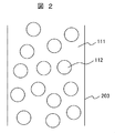
- FIG. 2 schematically shows a microscopic state of the mixed solution.
- the micro droplets of methanol 112 are dispersed in the oil 111 in the pipe 203.
- this mixed solution is introduced into the reaction tube 102 shown in FIG. 1, and irradiated with microwaves, heated, and reacted.
- the outlet temperature of the mixed liquid after the reaction is measured by the temperature measuring unit 108b shown in FIG. 1, and the output of the microwave is adjusted so as to be a desired temperature.
- the catalyst is preferably an alkali catalyst such as sodium hydroxide or potassium hydroxide.
- the catalyst is dispersed in a state dissolved in methanol 112. That is, the methanol 112 is a catalyst-containing raw material liquid.
- the interface area between the fat 111 and the methanol 112 is increased, so that the reaction can be speeded up.
- the methanol absorbs most of the microwaves and is heated. This is because the relative dielectric loss factor at a temperature of 25 ° C. of a microwave with a frequency of 2.45 GHz is 0.1 or less in the case of oils and fats, and is about 13 in the case of methanol, which is proportional to the relative dielectric loss factor. This is because the amount of heat generated is greater in methanol. Therefore, only methanol can be heated without heating the fats and oils. Therefore, it is not necessary to heat the whole liquid mixture, and the energy used can be suppressed.
- the fatty acid methyl ester which is the main component of the fuel component (biodiesel) generated by the reaction of the mixed solution, is easily dissolved in the oil 111, it moves to the oil 111 (oil phase).
- the fat 111 has a small relative dielectric loss factor and hardly absorbs microwaves, so it is hardly heated by the microwaves and its temperature is lower than the interface where the reaction proceeds.
- microwave irradiation unit 100 will be described in detail.
- the microwave oscillated from the microwave oscillator enters the movable short circuit plate 104 and is reflected by the movable short circuit plate 104. At this time, a standing wave is generated in the microwave irradiation unit 100 due to interference between the incident wave and the reflected wave. Since the microwave energy absorbed by the substance is proportional to the square of the electric field strength, if the reaction tube 102 is installed in a portion where the electric field strength of the generated standing wave is increased, the reaction liquid flowing through the reaction tube 102 is efficient. It becomes possible to absorb the microwave well.
- the stub tuner 103 is installed to adjust the impedance in the microwave irradiation unit 100. In addition, if the impedance in the microwave irradiation part 100 can be adjusted, it may not be the stub tuner 103, for example, an EH tuner etc. may be sufficient.
- the movable short-circuit plate 104 is movable in the traveling direction of the microwave, and the position of the standing wave can be finely adjusted by adjusting the position of the movable short-circuit plate 104. Microwaves can be absorbed.
- the reaction tube 102 is preferably made of a material that easily transmits microwaves and has a low relative dielectric loss factor. Specifically, glass, resin, ceramic and the like.
- the shape is preferably a straight tube, a spiral tube, a multiple spiral tube, or the like, but is not limited thereto.
- the rectangular waveguide 501 is used.
- the waveguide 501 may have another shape such as a cylindrical shape.
- a transmission device such as a coaxial cable may be used instead of the waveguide.
- the microwave will diffusely reflect in the microwave oven, so the microwave cannot be efficiently absorbed by the reaction solution.
- the microwave is reacted.
- the liquid can be irradiated intensively, and the reaction liquid can be efficiently heated.
- FIG. 8 shows an example of a mixer.
- the mixer 300 is formed by combining an introduction part 301, a dispersion part 302, and a discharge part 303.
- a packing 304 is sandwiched between the introduction part 301 and the dispersion part 302, and a packing 305 is sandwiched between the dispersion part 302 and the discharge part 303.
- the introduction part 301 is provided with an oil / fat inlet 311 and a catalyst-containing raw material liquid inlet 312, and the oil and fat and the catalyst-containing raw material liquid that have flowed in through them are merged to form a mixed liquid at the dispersion part 302, and a discharge part It flows out from 303.
- the inner diameter of the flow path of the introduction part 301 was 2.5 mm.
- the dispersion part 302 is provided with an orifice having an inner diameter of 0.10 mm and a length of 0.30 mm.
- the liquid flows from a narrow area (orifice) of the flow path to a thick area, and the flow path is rapidly expanded, whereby the mixing of the oil and the catalyst-containing raw material liquid is promoted, and a desired mixed liquid (dispersion) is obtained.
- the fat is sunflower oil and is a continuous phase.
- the catalyst-containing raw material liquid is a dispersed phase in which a catalyst is dispersed in methanol.
- the configuration of the fuel synthesizing apparatus in the present embodiment is the same as that in the first embodiment.
- the difference is that the catalyst is an ionic liquid. Therefore, in this embodiment, the catalyst-containing raw material liquid obtained by mixing the raw material methanol and the ionic liquid having the function of the catalyst is stored in the chemical liquid tank 130b shown in FIG.
- An alkali catalyst such as sodium hydroxide or potassium hydroxide may be further added to the catalyst-containing raw material liquid.
- the ionic liquid refers to a salt in a liquid state, and in a narrow sense, refers to a compound that includes a cation and an anion and is liquid at room temperature and normal pressure.
- the ionic liquid is classified into a pyridine type, an alicyclic amine type, and an aliphatic amine type depending on the kind of the cation.
- Specific examples of the cation include 1,3-dialkylimidazolium ions and 1,3,5-trialkylimidazolium ions having an imidazole ring, and 1-alkylpyridinium ions having a pyridine ring.
- Specific examples of anions include tetrafluoroborate (BF 4 ⁇ ), hexafluorophosphate (PF 6 ⁇ ), and the like.
- This ionic liquid has various excellent characteristics such as non-volatility, incombustibility, and stability. Among them, there is an idea that an ionic liquid is regarded as a novel surfactant.
- an imidazolium type ionic liquid if a long-chain alkyl group is used as one of the alkyl groups bonded to the imidazolium ring, the chemical structure is similar to that of a cationic surfactant. Therefore, when such an ionic liquid is dissolved in water, a molecular assembly similar to the surfactant is formed.
- C 4 mimBF 4 1-butyl-3-methylimidazolium tetrafluoroborate
- C 8 mimCl, C 8 mimI, C 4 mimC 8 SO 4 C 9 mimBr, C 10 mimBr, C 10 mimCl, C 12 mimBr, C 12 mimCl, C 12 mimBF 4 , C 14 mimBr, C 16 mimBr and the like are available.
- the alkyl chain is C 8 or more, micelles are likely to be formed as in the case of ordinary surfactants.
- FIG. 3 shows a microscopic state of the liquid mixture generated through the mixer 101 shown in FIG. 1 when an ionic liquid having such characteristics is selected and used.
- the heating by the microwave is the same as in Example 1, and most of the microwave is absorbed by the methanol 112 and heated. Therefore, it is possible to heat only the methanol 112 without heating the oil 111.
- the ionic liquid 115 concentrated on the interface between the fat 111 and the methanol 112 absorbs microwaves more easily than the methanol 112, so the interface portion is locally heated. The Therefore, only the periphery of the ionic liquid 115 for which a reaction is desired becomes a high temperature. Therefore, the energy supplied for the reaction can be suppressed.
- the mixed liquid after heating contains a fuel component (biodiesel) as a product, glycerin as a by-product, and remaining methanol and ionic liquid, but biodiesel and ionic liquid do not mix with each other. Can be easily separated. Further, since water and methanol can be easily separated by a method such as distillation, the ionic liquid and other substances can be easily separated.
- the ionic liquid can be reused, and the amount of waste can be suppressed.
- the configuration of the fuel synthesizing apparatus in the present embodiment is the same as that in the first embodiment.
- the difference is that the catalyst is a solid catalyst. Therefore, in the present embodiment, the catalyst-containing raw material liquid obtained by mixing the raw material methanol and the solid catalyst is stored in the chemical liquid tank 130b shown in FIG.
- the solid catalyst is previously mixed with methanol. Further, even during storage, the solid catalyst is uniformly dispersed in methanol by stirring the catalyst-containing raw material liquid constantly or intermittently with the stirrer 131b shown in FIG.
- the stirrer 131b may be a magnetic stirrer or an ultrasonic stirrer as long as the catalyst-containing raw material liquid can be stirred.
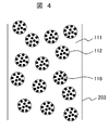
- FIG. 4 shows a microscopic state of the mixed liquid generated by passing through the mixer 101 shown in FIG. 1 when a solid catalyst is used.
- fine droplets of methanol 112 are generated in the oil 111 flowing through the pipe 203.
- the solid catalyst 116 is included in the fine droplets of methanol 112.
- the solid catalyst include lime, clay, metal oxide, calcium oxide, calcium hydroxide, ion exchange resin, and zirconia sulfate, but are not limited thereto.
- the calorific value of a substance heated by microwaves is not only proportional to the relative dielectric loss rate of the substance, but also proportional to the electrical conductivity and magnetic loss rate of the substance. Therefore, when the solid catalyst 116 that has a larger specific dielectric loss factor, electrical conductivity, or magnetic loss factor and absorbs microwaves more easily than the methanol 112 is used, the mixture including the oil 111, the methanol 112, and the solid catalyst 116 is mixed. In the liquid, the solid catalyst 116 can be selectively heated by microwaves.
- the solid catalyst 116 is contained in the fine droplets of methanol 112, it always exists in the vicinity of the interface between the oil 111 and the methanol 112 where the reaction occurs, and is selectively heated by the microwave. For this reason, the vicinity of the interface between the fat 111 and the methanol 112 is locally at a high temperature, and the reaction can be promoted. Furthermore, since it is not necessary to heat the whole liquid mixture, the energy to be used can be suppressed.
- the mixed liquid after the reaction contains a fuel component (biodiesel) as a product, glycerin as a by-product, and remaining methanol and a solid catalyst.
- a fuel component biodiesel
- glycerin as a by-product
- remaining methanol and a solid catalyst.
- the solid catalyst can be easily separated by a filter or the like. Therefore, the separated and recovered solid catalyst can be reused over and over again, and the amount of waste can be reduced.
- the difference from the first embodiment is that methanol and the catalyst are stored in separate tanks.
- FIG. 5 shows a schematic configuration of the fuel synthesizing apparatus of the present embodiment. Only the differences from the first embodiment will be described with reference to FIG.
- a raw material tank 230b for storing methanol as a raw material and a catalyst tank 230c for storing ionic liquid as a catalyst are provided separately.
- Pipes 211b and 211c are connected to these tanks, respectively.
- the pipes 211b and 211c are connected to the mixer 101b, and the mixer 101b is connected to the mixer 101a via the pipe 212.
- the pipes 211b and 211c are provided with liquid feeding pumps 215b and 215c.
- the mixer 101b is a premixing unit.
- the raw material methanol and the catalyst ionic liquid are sent to the mixer 101b by the liquid feed pumps 215b and 215c, respectively, and mixed therein to become a catalyst-containing raw material liquid.
- This catalyst-containing raw material liquid is sent to the mixer 101a and mixed with the oil or fat as the raw material to form a mixed liquid.
- the width of the flow path (the diameter or minimum dimension of the flow path) inside the mixers 101a and 101b is several tens of ⁇ m to several hundreds of ⁇ m.
- the amount of ionic liquid relative to methanol can be controlled.
- the particle diameter of the fine droplets of the catalyst-containing raw material liquid can be controlled by using the mixer 101a having the flow path.
- the reaction can be performed uniformly and with high efficiency, and the yield of the fuel component can be stabilized.
- the difference from the fourth embodiment is that a back pressure valve is provided on the downstream side of the reaction tube.
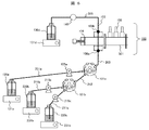
- FIG. 6 shows a schematic configuration of the fuel synthesizing apparatus of the present embodiment. Only the differences from the fourth embodiment will be described with reference to FIG.
- a back pressure valve 140 is installed in the pipe 205 on the downstream side of the reaction tube 102.
- the fats and oils, methanol, and ionic liquid constituting the mixed liquid are pressurized by the liquid feed pumps 105 a, 215 b, and 215 c, introduced into the mixer 101 a, reacted in the reaction tube 102, and the product liquid tank 130 d through the pipe 205. Sent to.
- the back pressure valve 140 since the back pressure valve 140 is installed in the pipe 205, the upstream side of the back pressure valve 140 is in a pressurized state, and boiling of the mixed liquid and product liquid in the reaction tube 102 is suppressed. Therefore, the liquid mixture can be reacted with the temperature kept high.
- the methanol having the lowest boiling point among the components constituting the mixed solution is methanol, and its boiling point is about 64 ° C. When methanol boils, the reaction is significantly suppressed.
- the reaction can proceed in a liquid state even when the boiling point of methanol is 64 ° C. or higher.
- the higher the temperature the higher the reaction rate constant of the chemical reaction, so the reaction proceeds faster. Also in the transesterification reaction of this example, when the temperature is increased, the reaction rate constant increases and the reaction proceeds faster. Therefore, the chemical reaction itself can be promoted by installing the back pressure valve 140 downstream of the reaction tube 102 as in the present embodiment.
- the difference from the first embodiment in the configuration of the fuel synthesizing apparatus of the present embodiment is that a valve is provided in the piping and a part of the product liquid is refluxed from the product liquid tank between the mixer and the reaction tube. This is the point where piping is provided.
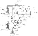
- FIG. 7 shows a schematic configuration of the fuel synthesizing apparatus of the present embodiment. Only the differences from the first embodiment will be described with reference to FIG.
- the pipes 201a and 201b are provided with valves 145a and 145b, respectively.
- the valves 145a and 145b are installed downstream of the liquid feed pumps 105a and 105b, respectively.
- a pipe 209 is provided between the product liquid tank 130 d and the pipe 203 on the upstream side of the reaction tube 102.
- a liquid feed pump 105 d is installed in the pipe 209 so that the product liquid can be pressurized and returned to the pipe 203.
- the pipe 209 is provided with a valve 145c.
- the catalyst which can be used in a present Example is alkali catalysts, such as sodium hydroxide and potassium hydroxide, an ionic liquid, a solid catalyst.
- the valve 145a and 145b are opened and the valve 145c is closed. Thereafter, when the product liquid is accumulated in the product liquid tank 130d, the valve 145c is opened, the valves 145a and 145b are closed, and the liquid feed pump 105d is operated. As a result, the product liquid stored in the product liquid tank 130d is again introduced into the reaction tube 102 and irradiated with microwaves.
- the reaction further proceeds by microwave irradiation. Then, in a state where the concentration of the fuel component is increased, the fuel component returns to the product liquid tank 130d and circulates.
- valve 145a and the valve 145b may be opened and the liquid feed pump 105a and the liquid feed pump 105b may be kept operating.
- the new liquid mixture of fats and oils, methanol and catalyst mixed in the mixer 101 and the product liquid from the product liquid tank 130 d which has reacted once or more are mixed and introduced into the reaction tube 102.
- the mixed liquid heated by the microwave in the reaction tube 102 circulates and is heated by the microwave in the reaction tube 102 many times, even if the reaction is not completed by a single heating, it is ensured.
- the reaction can be allowed to proceed to the end, and the product biodiesel can be obtained in high yield.
- the configuration of the fuel synthesizing apparatus in this embodiment is the same as that in the above embodiment, but after introducing the mixed liquid into the reaction tube in the operation of the apparatus, the additional introduction is stopped and the mixed liquid is retained in the reaction tube. The point that the reaction proceeds by irradiation with microwaves for a long time is different.
- the liquid feed pumps 105a and 105b are operated to introduce the mixed liquid into the reaction tube 102, and the microwave irradiation unit 100 irradiates the microwave to heat the mixed liquid. Then, in a state where this mixed liquid fills the reaction tube 102, the liquid feed pumps 105a and 105b are stopped for a certain period of time, microwave irradiation is continued, and the mixed liquid is further heated. At this time, the temperature of the mixed solution is measured by the temperature measuring units 108a and 108b, and the output of the microwave is adjusted so as to be a desired temperature.
- the liquid feed pumps 105a and 105b are operated again and heated, and the reacted liquid mixture is sent to the product liquid tank 130d and unheated mixing.
- the liquid is introduced into the reaction tube 102.
- the liquid feed pumps 105a and 105b are stopped for a certain time, irradiated with microwaves, and the mixed liquid is heated.
- the heating time can be lengthened, the reaction can be advanced, and the concentration of the fuel component can be increased.
- the microwave may be constantly irradiated, or may be irradiated only when the liquid feeding pumps 105a and 105b are stopped and the mixed liquid is stopped in the reaction tube 102. .
- the temperature distribution between the inlet and outlet of the reaction tube 102 can be reduced. Further, by adjusting the output of the microwave, it is possible to control the temperature so that the temperature of the entire liquid mixture in the reaction tube 102 is raised to a desired temperature and kept constant at that temperature. Thereby, reaction can be advanced reliably and a desired yield can be obtained.
- fine alcohol droplets can be dispersed in fats and oils.
- the contact interface area of fats and oils and alcohol increases, and it becomes possible to advance reaction rapidly.
- an ionic liquid when used as a catalyst, an alcohol and an ionic liquid are mixed in advance to prepare a catalyst-containing raw material liquid, and then the catalyst-containing raw material liquid and the fat / oil are mixed so that the oil / fat is contained. Fine droplets of the catalyst raw material liquid can be dispersed, and the ionic liquid can be concentrated in the vicinity of these interfaces, so that the reaction can proceed rapidly.
- alcohol since alcohol has a higher dielectric loss factor than oil and fat, and absorbs microwaves, the alcohol is mainly heated, and the reaction proceeds at the interface between the fine droplets of the catalyst-containing raw material liquid containing alcohol and the oil and fat. . Oils and fats hardly absorb microwaves, and only alcohol absorbs microwaves and is heated, so that the entire mixture is not heated, and microwave energy can be efficiently used for the reaction. .
- the oil and fat and alcohol are used when microwaves are irradiated to the fine droplets of the catalyst-containing raw material liquid containing the alcohol and ionic liquid present in the fat and oil.
- Microwaves are mainly absorbed and heated by the ionic liquid concentrated near the interface. By this action, the reaction is promoted and it is not necessary to heat the whole liquid mixture, so that microwave energy can be efficiently used for the reaction.
- the catalyst when a solid catalyst that easily absorbs microwaves is selected as the catalyst, when the microwave is irradiated to the fine droplets of the catalyst-containing raw material liquid containing the alcohol and the solid catalyst present in the oil and fat, the oil and the alcohol and Microwaves are mainly absorbed and heated by the solid catalyst concentrated near the interface. By this action, the reaction is promoted and it is not necessary to heat the whole liquid mixture, so that microwave energy can be efficiently used for the reaction. Further, since the solid catalyst can be easily separated, it can be reused and the amount of waste can be reduced.
- SYMBOLS 100 Microwave irradiation part, 101, 101a, 101b: Mixer, 102: Reaction tube, 103: Stub tuner, 104: Movable short circuit board, 105a, 105b, 105d, 215b, 215c: Liquid feeding pump, 108a, 108b: Temperature measurement unit, 111: oil and fat, 112: methanol, 115: ionic liquid, 116: solid catalyst, 130a, 230b: raw material tank, 130b: chemical liquid tank, 130d: product liquid tank, 131a, 131b, 131d, 231b, 231c: Stirrer, 140: back pressure valve, 145a, 145b, 145c: valve, 230c: catalyst tank, 300: mixer, 301: introduction part, 302: dispersion part, 303: discharge part, 304, 305: packing, 306: bolt, 311: Oil / fat inlet, 312: Catalyst
Landscapes
- Chemical & Material Sciences (AREA)
- Oil, Petroleum & Natural Gas (AREA)
- Chemical Kinetics & Catalysis (AREA)
- Organic Chemistry (AREA)
- General Health & Medical Sciences (AREA)
- Toxicology (AREA)
- Physics & Mathematics (AREA)
- Health & Medical Sciences (AREA)
- Engineering & Computer Science (AREA)
- General Chemical & Material Sciences (AREA)
- Electromagnetism (AREA)
- Fats And Perfumes (AREA)
- Liquid Carbonaceous Fuels (AREA)
Description
Claims (14)
- アルコールと触媒とを混合して含触媒原料液を作製した後、該含触媒原料液と油脂とを混合して混合液を作製し、該混合液にマイクロ波を照射することにより、前記油脂を構成する脂肪酸と前記アルコールとが結合した脂肪酸エステルを合成することを特徴とする燃料合成方法。
- 前記混合液は、前記油脂に前記含触媒原料液の液滴が分散したものであることを特徴とする請求項1記載の燃料合成方法。
- 前記触媒は、イオン液体であることを特徴とする請求項1又は2に記載の燃料合成方法。
- 前記イオン液体の比誘電損率は、メタノールの比誘電損率よりも大きいことを特徴とする請求項3記載の燃料合成方法。
- 前記触媒は、固体であることを特徴とする請求項1又は2に記載の燃料合成方法。
- 前記マイクロ波の照射は、前記混合液を標準気圧以上に加圧して行い、前記混合液の温度を標準沸点以上にすることを特徴とする請求項1~5のいずれか一項に記載の燃料合成方法。
- 前記マイクロ波を照射した前記混合液に、少なくとももう一度前記マイクロ波を照射することを特徴とする請求項1~6のいずれか一項に記載の燃料合成方法。
- 前記マイクロ波の照射は、前記混合液の導入を停止し、前記混合液が滞留した状態で行い、その後、前記混合液を入れ替え、再び前記混合液の導入を停止し、前記混合液が滞留した状態で前記マイクロ波を照射することを特徴とする請求項1~7のいずれか一項に記載の燃料合成方法。
- アルコール及び触媒を含む含触媒原料液と油脂とを混合して混合液を作製する混合部と、該混合液にマイクロ波を照射するマイクロ波照射部とを備え、該マイクロ波照射部は、前記油脂を構成する脂肪酸と前記アルコールとが結合した脂肪酸エステルを合成する機能を有することを特徴とする燃料合成装置。
- 前記混合液は、前記油脂に前記含触媒原料液の液滴が分散したものであることを特徴とする請求項9記載の燃料合成装置。
- さらに、前記アルコールと前記触媒とを混合して前記含触媒原料液を作製する予混合部を備えたことを特徴とする請求項9又は10に記載の燃料合成装置。
- 前記マイクロ波照射部における前記混合液を加圧可能としたことを特徴とする請求項9~11のいずれか一項に記載の燃料合成装置。
- さらに、前記マイクロ波照射部を通過した前記混合液を前記マイクロ波照射部に還流する流路を備えたことを特徴とする請求項9~12のいずれか一項に記載の燃料合成装置。
- 前記マイクロ波照射部は、導入を停止し滞留している前記混合液にマイクロ波を照射することを特徴とする請求項9~13のいずれか一項に記載の燃料合成装置。
Priority Applications (3)
| Application Number | Priority Date | Filing Date | Title |
|---|---|---|---|
| PCT/JP2012/064632 WO2013183137A1 (ja) | 2012-06-07 | 2012-06-07 | 燃料合成方法及び燃料合成装置 |
| US14/405,790 US20150191665A1 (en) | 2012-06-07 | 2012-06-07 | Fuel synthesizing method and fuel synthesizing apparatus |
| JP2014519758A JPWO2013183137A1 (ja) | 2012-06-07 | 2012-06-07 | 燃料合成方法及び燃料合成装置 |
Applications Claiming Priority (1)
| Application Number | Priority Date | Filing Date | Title |
|---|---|---|---|
| PCT/JP2012/064632 WO2013183137A1 (ja) | 2012-06-07 | 2012-06-07 | 燃料合成方法及び燃料合成装置 |
Publications (1)
| Publication Number | Publication Date |
|---|---|
| WO2013183137A1 true WO2013183137A1 (ja) | 2013-12-12 |
Family
ID=49711554
Family Applications (1)
| Application Number | Title | Priority Date | Filing Date |
|---|---|---|---|
| PCT/JP2012/064632 Ceased WO2013183137A1 (ja) | 2012-06-07 | 2012-06-07 | 燃料合成方法及び燃料合成装置 |
Country Status (3)
| Country | Link |
|---|---|
| US (1) | US20150191665A1 (ja) |
| JP (1) | JPWO2013183137A1 (ja) |
| WO (1) | WO2013183137A1 (ja) |
Cited By (2)
| Publication number | Priority date | Publication date | Assignee | Title |
|---|---|---|---|---|
| CN106943982A (zh) * | 2015-12-30 | 2017-07-14 | 武珍机工株式会社 | 生物柴油制造用反应器 |
| US10596561B2 (en) | 2015-03-31 | 2020-03-24 | Uop Llc | Halometallate ionic liquid micro-emulsions |
Citations (6)
| Publication number | Priority date | Publication date | Assignee | Title |
|---|---|---|---|---|
| JP2008502780A (ja) * | 2004-06-15 | 2008-01-31 | カーネギー メロン ユニヴァーシティ | バイオディーゼルを生産する方法 |
| JP2008533232A (ja) * | 2005-03-11 | 2008-08-21 | ザ クィーンズ ユニヴァーシティー オブ ベルファスト | バイオディーゼルの製造 |
| WO2009110245A1 (ja) * | 2008-03-05 | 2009-09-11 | マイクロ波環境化学株式会社 | マイクロ波化学反応装置及びその装置を用いた反応方法 |
| JP2010250190A (ja) * | 2009-04-20 | 2010-11-04 | Ricoh Co Ltd | 定着装置及び画像形成装置 |
| JP2011140020A (ja) * | 2009-12-28 | 2011-07-21 | Petroleo Brasileiro Sa | 油中水型エマルジョンの処理方法 |
| JP2011235263A (ja) * | 2010-05-13 | 2011-11-24 | Microwave Chemical Co Ltd | 化学反応装置、及び化学反応方法 |
-
2012
- 2012-06-07 US US14/405,790 patent/US20150191665A1/en not_active Abandoned
- 2012-06-07 WO PCT/JP2012/064632 patent/WO2013183137A1/ja not_active Ceased
- 2012-06-07 JP JP2014519758A patent/JPWO2013183137A1/ja active Pending
Patent Citations (6)
| Publication number | Priority date | Publication date | Assignee | Title |
|---|---|---|---|---|
| JP2008502780A (ja) * | 2004-06-15 | 2008-01-31 | カーネギー メロン ユニヴァーシティ | バイオディーゼルを生産する方法 |
| JP2008533232A (ja) * | 2005-03-11 | 2008-08-21 | ザ クィーンズ ユニヴァーシティー オブ ベルファスト | バイオディーゼルの製造 |
| WO2009110245A1 (ja) * | 2008-03-05 | 2009-09-11 | マイクロ波環境化学株式会社 | マイクロ波化学反応装置及びその装置を用いた反応方法 |
| JP2010250190A (ja) * | 2009-04-20 | 2010-11-04 | Ricoh Co Ltd | 定着装置及び画像形成装置 |
| JP2011140020A (ja) * | 2009-12-28 | 2011-07-21 | Petroleo Brasileiro Sa | 油中水型エマルジョンの処理方法 |
| JP2011235263A (ja) * | 2010-05-13 | 2011-11-24 | Microwave Chemical Co Ltd | 化学反応装置、及び化学反応方法 |
Cited By (3)
| Publication number | Priority date | Publication date | Assignee | Title |
|---|---|---|---|---|
| US10596561B2 (en) | 2015-03-31 | 2020-03-24 | Uop Llc | Halometallate ionic liquid micro-emulsions |
| US10814317B2 (en) | 2015-03-31 | 2020-10-27 | Uop Llc | Hydrocarbon processes using halometallate ionic liquid micro-emulsions |
| CN106943982A (zh) * | 2015-12-30 | 2017-07-14 | 武珍机工株式会社 | 生物柴油制造用反应器 |
Also Published As
| Publication number | Publication date |
|---|---|
| JPWO2013183137A1 (ja) | 2016-01-21 |
| US20150191665A1 (en) | 2015-07-09 |
Similar Documents
| Publication | Publication Date | Title |
|---|---|---|
| US8039652B2 (en) | Methods for producing biodiesel | |
| Wen et al. | Intensification of biodiesel synthesis using zigzag micro-channel reactors | |
| Okitsu et al. | Ultrasound-assisted production of biodiesel fuel from vegetable oils in a small scale circulation process | |
| Elkady et al. | Production of biodiesel from waste vegetable oil via KM micromixer | |
| Mazubert et al. | Key role of temperature monitoring in interpretation of microwave effect on transesterification and esterification reactions for biodiesel production | |
| Choedkiatsakul et al. | Integrated flow reactor that combines high-shear mixing and microwave irradiation for biodiesel production | |
| Rahimi et al. | Transesterification of soybean oil in four-way micromixers for biodiesel production using a cosolvent | |
| US20090000941A1 (en) | Ultrasonic and microwave methods for enhancing the rate of a chemical reaction and apparatus for such methods | |
| CN102448603A (zh) | 用于在高温下连续进行化学反应的设备 | |
| Gupta et al. | Intensified transesterification of mixture of edible and nonedible oils in reverse flow helical coil reactor for biodiesel production | |
| WO2009110245A1 (ja) | マイクロ波化学反応装置及びその装置を用いた反応方法 | |
| JP2012531384A (ja) | 芳香族カルボン酸のエステルの連続的製造方法 | |
| Menalla et al. | Hydrothermal hydrolysis of triglycerides: Tunable and intensified production of diglycerides, monoglycerides, and fatty acids | |
| AU2011212228B2 (en) | Method and apparatus for esterifying fatty acid | |
| WO2013183137A1 (ja) | 燃料合成方法及び燃料合成装置 | |
| US20110290789A1 (en) | Microwave heating apparatus | |
| Pongraktham et al. | Circulation process of methyl ester production from pretreated sludge palm oil using CaO/ABS catalytic static mixer coupled with an ultrasonic clamp | |
| Zou et al. | A novel ultrasonic reactor for continuous production of biodiesel from waste acid oil | |
| JP2007307440A (ja) | 化学反応装置 | |
| KR20140093297A (ko) | 전자기파를 이용한 연속식 바이오디젤 제조장치 | |
| KR101150842B1 (ko) | 마이크로파 도파관을 이용한 튜브방식 바이오디젤 제조장치 | |
| Asghari et al. | Optimization of methyl ester synthesis using gas/liquid phase pulsed discharge plasma in a novel oscillatory slug flow reactor | |
| Scares et al. | Feasibility of biodiesel production in a continuous flow microwave reactor with static mixing | |
| Bagal et al. | Optimization of esterification of palm fatty acid distillate using conventional approach and its comparison with ultrasonic and microwave irradiation | |
| JP7832692B2 (ja) | 単一支配モードのマイクロ波反応器 |
Legal Events
| Date | Code | Title | Description |
|---|---|---|---|
| 121 | Ep: the epo has been informed by wipo that ep was designated in this application |
Ref document number: 12878356 Country of ref document: EP Kind code of ref document: A1 |
|
| ENP | Entry into the national phase |
Ref document number: 2014519758 Country of ref document: JP Kind code of ref document: A |
|
| WWE | Wipo information: entry into national phase |
Ref document number: 14405790 Country of ref document: US |
|
| NENP | Non-entry into the national phase |
Ref country code: DE |
|
| 122 | Ep: pct application non-entry in european phase |
Ref document number: 12878356 Country of ref document: EP Kind code of ref document: A1 |