WO2013179772A1 - 開閉器ユニットまたはスイッチギヤ - Google Patents
開閉器ユニットまたはスイッチギヤ Download PDFInfo
- Publication number
- WO2013179772A1 WO2013179772A1 PCT/JP2013/060580 JP2013060580W WO2013179772A1 WO 2013179772 A1 WO2013179772 A1 WO 2013179772A1 JP 2013060580 W JP2013060580 W JP 2013060580W WO 2013179772 A1 WO2013179772 A1 WO 2013179772A1
- Authority
- WO
- WIPO (PCT)
- Prior art keywords
- switch
- switch unit
- fin
- resin
- heat
- Prior art date
Links
Images

Classifications
-
- H—ELECTRICITY
- H01—ELECTRIC ELEMENTS
- H01H—ELECTRIC SWITCHES; RELAYS; SELECTORS; EMERGENCY PROTECTIVE DEVICES
- H01H33/00—High-tension or heavy-current switches with arc-extinguishing or arc-preventing means
- H01H33/60—Switches wherein the means for extinguishing or preventing the arc do not include separate means for obtaining or increasing flow of arc-extinguishing fluid
- H01H33/66—Vacuum switches
- H01H33/662—Housings or protective screens
- H01H33/66207—Specific housing details, e.g. sealing, soldering or brazing
-
- H—ELECTRICITY
- H01—ELECTRIC ELEMENTS
- H01H—ELECTRIC SWITCHES; RELAYS; SELECTORS; EMERGENCY PROTECTIVE DEVICES
- H01H33/00—High-tension or heavy-current switches with arc-extinguishing or arc-preventing means
- H01H33/60—Switches wherein the means for extinguishing or preventing the arc do not include separate means for obtaining or increasing flow of arc-extinguishing fluid
- H01H33/66—Vacuum switches
- H01H33/6606—Terminal arrangements
- H01H2033/6613—Cooling arrangements directly associated with the terminal arrangements
-
- H—ELECTRICITY
- H01—ELECTRIC ELEMENTS
- H01H—ELECTRIC SWITCHES; RELAYS; SELECTORS; EMERGENCY PROTECTIVE DEVICES
- H01H33/00—High-tension or heavy-current switches with arc-extinguishing or arc-preventing means
- H01H33/60—Switches wherein the means for extinguishing or preventing the arc do not include separate means for obtaining or increasing flow of arc-extinguishing fluid
- H01H33/66—Vacuum switches
- H01H33/662—Housings or protective screens
- H01H33/66207—Specific housing details, e.g. sealing, soldering or brazing
- H01H2033/66215—Details relating to the soldering or brazing of vacuum switch housings
-
- H—ELECTRICITY
- H01—ELECTRIC ELEMENTS
- H01H—ELECTRIC SWITCHES; RELAYS; SELECTORS; EMERGENCY PROTECTIVE DEVICES
- H01H33/00—High-tension or heavy-current switches with arc-extinguishing or arc-preventing means
- H01H33/60—Switches wherein the means for extinguishing or preventing the arc do not include separate means for obtaining or increasing flow of arc-extinguishing fluid
- H01H33/66—Vacuum switches
- H01H33/662—Housings or protective screens
- H01H33/66207—Specific housing details, e.g. sealing, soldering or brazing
- H01H2033/6623—Details relating to the encasing or the outside layers of the vacuum switch housings
-
- H—ELECTRICITY
- H01—ELECTRIC ELEMENTS
- H01H—ELECTRIC SWITCHES; RELAYS; SELECTORS; EMERGENCY PROTECTIVE DEVICES
- H01H33/00—High-tension or heavy-current switches with arc-extinguishing or arc-preventing means
- H01H33/60—Switches wherein the means for extinguishing or preventing the arc do not include separate means for obtaining or increasing flow of arc-extinguishing fluid
- H01H33/66—Vacuum switches
- H01H33/666—Operating arrangements
- H01H33/6661—Combination with other type of switch, e.g. for load break switches
Definitions
- the present invention relates to a switch unit or switch gear, and more particularly to cooling of a switch unit or switch gear that is solid-insulated with an insulating resin.
- the switchgear is arranged in the power system as a power receiving and distributing device, and receives the generated power sent from the power plant and distributes it to the load side.
- the switch unit is a main part of the switch gear that is disposed inside the switch gear and accommodates the switch.
- the shape connecting the bottoms of the fins is a rectangular shape in a plan view, but the vacuum valve formed inside the resin layer is cylindrical, and the position of the bottom of the fins and the resin There is no correlation in the internal shape of the layer.
- the resin has lower thermal conductivity than the metal and a temperature distribution is generated. Therefore, it is difficult to expect a dramatic improvement in the heat dissipation effect even if the fin is simply provided large.
- the switch gear is installed in a limited space, it is not desirable to increase the size.
- an object of the present invention is to provide a switch unit or a switch gear that can increase the heat dissipation and prevent an increase in size.
- a switch unit includes a fixed electrode, a movable electrode facing the fixed electrode and operating in the axial direction so as to contact or separate from the fixed electrode, A switch having a bus-side conductor connected to the electrode and connected to the bus-side, and a load-side conductor connected to the other electrode and connected to the load side, and covers the periphery of the switch
- the insulating resin is formed with fins in the circumferential direction on the outer surface of the insulating resin, and the distance between the outer periphery of the switch and the bottom of the fin is It is formed so as to be substantially constant in the direction.
- FIG. 1 It is a sectional side view of the switch unit concerning Example 1. It is AA 'sectional drawing of the switch unit concerning Example 1.
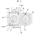
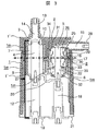
- FIG. 2 It is a sectional side view of the switch unit concerning Example 2. It is AA 'sectional drawing of the switch unit concerning Example 2.
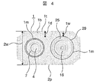
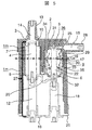
- FIG. It is a sectional side view of the switch unit concerning Example 3. It is AA 'sectional drawing of the switch unit concerning Example 3.
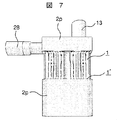
- FIG. It is an external view of the switch unit concerning Example 3.
- FIG. It is a figure which shows the switchgear which concerns on Example 4.
- Example 1 will be described with reference to FIGS.
- the switch unit includes a metal case 21 that is grounded, an insulating resin 2 such as epoxy that is connected to the metal case 21, and an integral casting using the insulating resin 2.
- the vacuum valve 26 and the ground disconnection portion 27, the bus bushing 13 and the cable bushing 28 are mainly configured.
- the vacuum valve 26 includes a fixed side electrode 16, a movable side in a vacuum container 8 configured by connecting a fixed side ceramic insulating cylinder 29, a movable side ceramic insulating cylinder 30, a fixed side end plate 31 and a movable side end plate 32.
- a shield 25 is provided.
- the fixed-side conductor 5 is connected to the cable bushing center conductor 15 so that power can be distributed to the load side.
- the cable bushing center conductor 15 is arranged in a direction orthogonal to the fixed-side conductor 5, and the conductor is concentrated at the portion sandwiched between the cable bushing center conductor 15 and the fixed-side conductor 5, and heat tends to rise during use. .
- the heat generation density increases and heat accumulates during use.
- a bellows 22 for realizing the movement of the movable conductor 6 is arranged on the movable side while maintaining the vacuum state in the vacuum valve 26.
- the vacuum valve 26 is turned on and off by allowing the movable electrode 17 and the movable conductor 6 to move in the axial direction while maintaining the internal vacuum by the bellows 22 connected to the movable end plate 32 and the movable conductor 6.
- the state is switched.
- a bellows shield 33 is provided in the vicinity of the connection between the bellows 22 and the movable conductor 6 in order to protect the bellows 22 from an arc or the like during opening and closing, and the concentration of the electric field at the end of the bellows 22 is alleviated.
- the movable side conductor 6 is connected to an operating rod 18 for a vacuum valve 26 that is air-insulated and solid-insulated, and the vacuum valve operating rod 18 is connected to an operating device (not shown).
- a fixed-side electric field relaxation shield 34 is arranged around the fixed-side ceramic insulating cylinder 29 to relieve electric field concentration at the connection portion with the fixed-side end plate 31, and a movable-side end is arranged around the movable-side ceramic insulating cylinder 30.
- movable side electric field relaxation shields 35 are respectively arranged.
- the ground disconnection portion 27 is connected to the bus-line bushing central conductor 14, the bushing fixed electrode 3 connected to the bus-line side via the center conductor, and the ground-side fixed electrode (guide) 19 that is set to the ground potential.
- the intermediate fixed electrode 9 is provided in the middle in the axial direction and electrically connected to the movable conductor 6 on the vacuum valve 26 side through the flexible conductor 20, and the inside is insulated in the air.
- Each of these fixed electrodes has a uniform inner diameter and is arranged in a straight line. With respect to each of these fixed electrodes, the ground disconnection portion movable conductor 4 moves linearly within the ground disconnection portion 27, so that it can be switched to three positions of closed, disconnection, and ground.
- the ground disconnection section movable conductor 4 is connected to an operation rod 12 that is air-insulated and solid-insulated, and can be moved by an operation mechanism (not shown).
- the portion that comes into contact with each of the fixed contacts is configured by the spring contact 10, so that the ground disconnection section movable conductor 4 is not obstructed to move and is reliably contacted by an elastic force. I can do it.
- the bus bushing 13 is configured by covering the periphery of the bus bushing central conductor 14 with the insulating resin 2
- the cable bushing 28 is configured by covering the periphery of the cable bushing central conductor 15 with the insulating resin 2.
- an epoxy resin is used as the material for the operation rod 12 for the vacuum valve, the operation rod 18 for the ground disconnection portion, and the insulating resin 2. Further, the operation rods 12 and 18 and the insulating resin 2 are individually insulated by themselves and gas insulated by the surrounding gas.
- the ground disconnection part movable conductor 4, the fixed side conductor 5, the movable side conductor 6, the aerial part 7, and the vacuum vessel 8 are integrally cast with the insulating resin 2, and the ground disconnection part movable conductor 4, the fixed side conductor 5, Resin heat radiating fins 1 formed of the same member as the insulating resin 2 are provided on the outer surface of the insulating resin 2 covering the movable conductor 6. As shown in FIG. 1, the outer surface closest to the heat generation source is at the highest height (location) 1 ′ of the resin radiating fin, and as the distance from the heat generation source increases, The height 1d of the resin heat radiation fin 1 is gradually (continuously) shortened.
- the heat generation source corresponds to a portion where conductors are concentrated (because the density of conductors serving as resistance is high) and a portion where electrodes are in contact (because contact resistance is generated).
- the insulating resin 2 is covered, the airtightness is increased, so that the heat dissipation performance is lowered and heat is more likely to accumulate.
- the heat dissipation performance is improved, and even if the heat generation property is high, it is difficult to become a heat accumulation place.
- the resin heat radiation fin sandwiched between the cable bushing center conductor 15 and the vacuum valve 26 corresponding to the portion where the conductor is concentrated and the periphery is covered with the insulating resin 2 increases the height of the fin.
- the height of the fin is lowered as the distance from the portion increases.
- the height of the fins provided around the spring contact 10 and the bushing fixed electrode 3 corresponding to the portion where the electrodes are in contact with each other and the periphery is covered with the insulating resin 2 is increased.
- a portion that is a heat generation source and is covered with the insulating resin 2 is referred to as a heat accumulation portion.
- the intermediate fixed electrode 9 connected to the periphery of the bus bushing 13 and the cable bushing 28 and the flexible conductor 20 having a high thermal resistance corresponds to a heat accumulation location.
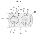
- the resin heat dissipating fins in the circumferential direction of the vacuum vessel 8 and the ground disconnecting portion 27 are arranged so that the resin heat dissipating fins are high in the circumferential direction as shown in FIG. It is configured to have a gradient.
- the bottom part 1b of the resin radiation fin is formed so that the distance 1W of the resin between the bottom part 1b of the resin radiation fin and the outer periphery of the vacuum vessel 8 can be kept constant in a circumferential shape. Heat dissipation performance can be enhanced while ensuring the minimum resin height required for strength and insulation performance.
- a minimum curvature necessary for ensuring strength and insulation performance is provided on the front end 1t and the bottom 1b of the resin heat radiation fin 1 according to the height 1d of the resin heat radiation fin 1.
- the curvature increases as the height 1d increases, and the curvature 1b-out on the inner diameter side (bottom) of the fin having the highest height in the radial direction of the fin has the highest height in the radial direction of the fin. It is formed larger than the curvature 1b-in on the inner diameter side of the fin other than the curvature 1b-out on the inner diameter side (bottom) of the fin.
- a flat portion (flat surface) 2p where the resin heat dissipating fins 1 are not provided is formed in a part of the outermost skin of the resin layer, and the tip 1t of the resin heat dissipating fin 1 of any height is more than the surface of the resin layer flat portion 2p. It is provided so as to be located inside (including the case where the tip of the resin radiating fin is located on the surface. It is necessary to prevent the tip of the resin radiating fin from protruding outward from the surface).
- the surface of the resin layer flat portion 2p includes a portion where the flat portion itself is not provided. Accordingly, even when a switch unit molded with resin is placed (laid down) at the time of assembly or the like, the load of the switch unit can be received by the flat portion 2p, and the tip of the resin radiating fin is not damaged.
- the grounding disconnection part movable conductor 4, the fixed side conductor 5, and the movable side conductor 6 are enlarged to reduce the current density, or the switching part. Then, it is possible to increase the contact pressure with respect to the electrodes 16 and 17 and reduce the contact resistance.
- the former leads to an increase in the size of the entire device, and the latter leads to an increase in the capacity per line because a large driving force is required by the operation mechanism, which may eventually increase the size of the device. is there.
- the switch unit is integrally cast with the insulating resin 2 as in the switch unit according to the present embodiment, if the entire outer surface of the insulating resin 2 has a fin shape for cooling, the insulating resin 2 The fins for cooling are uniformly attached to the portion where the temperature difference between the outer surface and the switchgear panel in which the switch unit is housed is low, that is, the portion where there is little need to improve the heat radiation performance.
- the thermal conductivity is small compared to metal, so temperature distribution occurs in the insulating resin fins, and heat is not transmitted to locations away from the heat generating part. Even if a fin for radiating heat is provided at such a part, the degree of contribution to the improvement of heat radiating performance is small.
- Providing fins as a whole leads to an increase in the weight of the entire switch unit. Therefore, it is not necessary to provide fins unnecessarily, but to arrange fins at positions that can sufficiently contribute to improving heat dissipation performance, the shape of the fins and their mounting It is desirable to determine the position.
- the resin heat radiation fin sandwiched between the cable bushing center conductor 15 and the vacuum valve 26 has a larger fin height, and the height of the fin increases as the distance from the portion increases. To make it thinner. Further, the fin heights of the fins provided around the spring contact 10 and the bushing fixed electrode 3 are also increased, and the height of the fins is also reduced as the distance from the portion increases.
- the resin heat dissipating fins in the circumferential direction of the vacuum vessel 8 and the ground disconnection portion 27 are provided with a gradient in the circumferential height in order to ensure strength and insulation performance.
- the bottom 1b of the resin radiating fin is formed so that the distance 1W of the resin between the bottom 1b of the resin radiating fin and the outer periphery of the vacuum vessel 8 can be kept constant (that is, when there is one switch covered with the resin).
- the figure formed by connecting the bottoms of the resin radiating fins and the figure formed by the outer periphery of the switch are similar.If there are multiple switches covered with resin, the part between the switches However, the heat radiation performance can be improved while ensuring the minimum resin height necessary for strength and insulation performance.
- the curvature 1b-out on the inner diameter side of the fin having the highest radial height of the resin radiating fin is provided larger than the curvature 1b-in on the inner diameter side of the fins other than the fin having the highest height. This is because, since the fin having the highest height of the resin radiating fin has a relatively large deformation, the stress at the tip 1t and the bottom 1 of the resin radiating fin 1 may be concentrated. Concentration is reduced. In addition, it is understood that the electric field is relatively concentrated in the fin having the highest height.
- the curvature 1b-out on the inner diameter side of the fin having the highest radial direction of the resin radiating fin is set larger than the curvature 1b-in on the inner diameter side of the fin other than the fin having the highest height.
- Electric field concentration can be reduced. That is, by adopting the above configuration, it becomes possible to improve the resistance in terms of both stress and electric field strength.
- a flat portion 2p where the resin heat radiating fins 1 are not provided is formed in a part of the outermost skin of the resin layer, and the resin layer flat portions 2p are provided so as to be closer to the outer surface of the resin layer than the tips 1t of the resin heat radiating fins 1. Thereby, the resin heat radiation fin can be protected by the resin layer outer surface contact at the time of assembly or the like.
- Joule heat is generated in the current conduction part during current conduction.
- the generated Joule heat is transmitted to the surrounding medium and is radiated to the outside from the surrounding medium.
- the heat generated in both the cable bushing center conductor 15 and the conductor in the vacuum valve 26 is transmitted to the insulating resin 2 sandwiched between the cable bushing center conductor 15 and the vacuum valve 26, the heat dissipation performance is further improved. Need to be high.
- the resin heat radiation fin sandwiched between the cable bushing center conductor 15 and the vacuum valve 26 has a large fin height, and the fin height decreases as the distance from the portion increases. .
- part can improve heat dissipation performance by enlarging the height of a fin.
- the distance from the part that is a heat accumulation part is increased, the density of the conductor is reduced, and the heat is not in the vicinity of the heat generation part, and since the heat conductivity is small in the insulating resin fin, the heat from the heat accumulation part is also reduced. Since it becomes difficult to transmit, the necessity to improve heat dissipation performance from both viewpoints is reduced. Therefore, in order to prevent an increase in size, the height of the resin heat radiating fins 1 is gradually reduced as the distance from the portion that is the heat accumulation portion increases.
- the resin heat dissipating fins 1 provided at the portions are made larger in height, and the resin heat dissipating fins 1 are made thinner as they are separated from the portions.
- the cooling performance can be improved and the size is not increased more than necessary.
- the resin heat radiating fin 1 expands the heat transfer surface to the surroundings and lowers the heat density of the surface. Therefore, the larger the heat transfer area, the better the performance. However, even if the surface area is increased unnecessarily, a decrease in heat transfer coefficient on the surface and a decrease in heat transfer efficiency up to the tips of the resin heat radiation fins 1 are expected. That is, the resin radiating fin 1 is most effective when the entire heat radiating surface is at the same temperature as the heat source. Therefore, although the metal has a large thermal conductivity and the temperature distribution is not easily generated, the insulating resin 2 has a small thermal conductivity and the temperature distribution is significantly generated. Therefore, the height of the resin radiating fins 1 is not uniform. In order to effectively cool the resin heat radiating fins 1, the resin heat radiating fins 1 are provided with a gradient (gradients are provided in the longitudinal direction of the fins, the axial direction, and further in the circumferential direction).
- the resin heat dissipating fin 1 has a gradient in the longitudinal direction of the fin (the axial direction of the movable electrode), so that the height has no gradient.
- the cooling performance can be improved compared to the case.
- the bottom portion 1b of the resin heat radiation fin so that the resin distance 1W between the bottom portion 1b of the resin heat radiation fin and the outer periphery of the vacuum vessel 8 can be kept constant, the minimum necessary for strength and insulation performance is achieved.
- the heat dissipation performance can be enhanced while ensuring the resin height.
- a minimum curvature necessary for ensuring strength and insulation performance is provided at the tip 1t and the bottom 1b of the resin radiating fin 1 in accordance with the height 1d of the resin radiating fin 1 (the curvature increases as the height 1d increases).
- a portion of the outermost outer layer of the resin layer forms a flat portion 2p where the resin heat radiating fin 1 is not provided, and the resin layer flat portion 2p is located on the outer surface of the resin layer rather than the tip 1t of the resin heat radiating fin 1.
- the switch unit according to the present embodiment is formed by integrally molding a circuit breaker and a ground switch with the insulating resin 2, and can be miniaturized by optimizing while enhancing the insulation characteristics. .
- the resin radiating fin 1 is provided on the insulating resin 2 of the switch unit, and a height gradient is provided in the longitudinal direction and the circumferential direction, and the strength and insulating performance are provided at the tip 1t and the bottom 1b of the resin radiating fin.
- the minimum curvature necessary for securing is provided according to the size of the height 1d, it is more suitable. In addition, since enlargement can be prevented, realization of downsizing is not hindered. Rather, as a switch unit that takes heat dissipation performance into consideration, the switch unit is very downsized.
- the earthing switch is used as the earthing disconnection part and the disconnecting function is also integrated, in addition to the above points, further miniaturization is realized. Furthermore, by using both vacuum insulation and air insulation, it is possible to provide a switch that does not increase in size even when an air ground disconnection part is used. In this way, in the case of a switch unit that realizes miniaturization by using any one of these means or a combination of these means, the heat generation density is originally increased, but the heat radiation space is also reduced. Increasing the heat dissipation performance with the heat dissipating fins 1 is preferable without increasing the size of the apparatus.
- the insulating resin forms fins in the circumferential direction on the outer surface of the insulating resin, and the outer periphery of the vacuum valve and the air ground disconnection portion, and the resin radiating fins.
- the distance to the bottom is formed to be substantially constant in the circumferential shape, taking into account the temperature distribution that occurs due to the low thermal conductivity specific to the resin radiating fins, increasing heat dissipation and sacrificing cooling performance It is possible to prevent an unnecessarily large size as long as it is not in the range. Further, when the fin is not used, it is necessary to enlarge the entire device for heat dissipation.
- the provision of the fin improves the heat dissipation performance, and contributes to further miniaturization in terms of the entire device.
- the outer surface of the insulating resin 2 has a flat portion 2p, and the tip of the insulating resin 2 is formed so as to be located inside the surface of the flat portion 2p. Even when the switch unit after casting is laid with the insulating resin 2, the tip of the fin is not damaged.
- the curvature 1b-out on the inner diameter side of the fin having the highest radial height is larger than the curvature 1b-in on the inner diameter side of the fin other than the fin having the highest height in the radial direction. Therefore, the concentration of the electric field can be reduced while concentrating the stress of the fin having the highest height in the radial direction of the fin.
- the curvature on the inner diameter side is increased only for the fin having the highest height in the radial direction, but the curvature increases as the height in the radial direction of the fin increases. It is also effective to reduce the curvature as the height increases. Moreover, it becomes possible to ensure the strength and insulation performance of the end portion of the outer surface of the resin layer covering the conductor and the container.
- the resin radiating fins 1 are arranged in four directions whose directions are different by 90 ° as shown in FIG. 2, that is, the tips of the resin radiating fins 1 are in the air ground disconnection portion 27 or vacuum. Two sets of surfaces are formed, one set of surfaces facing each other with the bulb 26 interposed therebetween, and one set of surfaces facing each other with the air ground disconnection portion 27 and the vacuum valve 26 sandwiched therebetween. Therefore, even when the mold is removed after casting, the mold can be pulled out in the direction facing the resin heat radiating fin 1 (without being caught by the fin), and the manufacture is easy.
- Example 2 will be described with reference to FIGS. The description of the same parts as those in the first embodiment is omitted.
- the role of the insulating shield and the role of the heat dissipating member can be achieved at the same time.
- the metal heat sink 1m is connected and fixed to the bus bushing 13, the cable bushing 28, and the intermediate fixed electrode 9, which are heat storage locations, and the heat is radiated to the resin layer so that the temperature of the resin layer is high.
- the height of the resin radiating fin is increased (maximum height 1 ′), and the height is reduced as the distance from the portion increases.
- the height of the resin radiating fin 1 is highest around the heat radiating plate 1m closest to the surface of the insulating resin 2 among the heat radiating plates 1m, and away from the periphery of the heat radiating plate 1m closest to the surface of the insulating resin 2 in the axial direction. As a result, the slope becomes lower.
- the heat radiating plate 1m is provided between the vacuum valve 26 and the ground disconnection portion 27, around the vacuum valve 26 and around the ground disconnection portion 27, and the heat radiating plate 1m on the side close to the operating unit is brought close to the surface of the insulating resin 2. It is arranged.
- the metal heat sink 1m has a minimum curvature (roundness) necessary for insulation performance at the tip so that it can serve as an insulation shield.
- the heat from the heat accumulation point is moved to the part to be radiated.
- the height of the resin heat radiating fin 1 is the highest in the periphery of the heat radiating plate 1m closest to the surface of the insulating resin 2 among the heat radiating plates 1m, and the axial direction from the periphery of the heat radiating plate 1m closest to the surface of the insulating resin 2 The distance is lowered as the distance increases, so that the moved heat can be efficiently dissipated.
- the heat radiating plate 1m is formed (connected) around the conductor and the vacuum valve 26 at the end of the conductor inside the insulating resin 2 and the vacuum valve 26, the heat from the conductor and the vacuum valve 26 is dissipated. Since heat is transferred to the plate 1m and accumulated, the heat radiation fin 1m has the highest surface temperature in the outer surface of the insulating resin 2 near the heat sink 1m where the heat is accumulated. It is better to lower the part.
- the height of the resin radiating fins made of resin is not uniform in the longitudinal direction and the circumferential direction, but has a gradient, and the height of the resin radiating fins of the heat accumulating portion is increased in order to achieve further effects. It is common in that it is the highest and the cooling performance is improved.
- Example 3 will be described with reference to FIGS. Also in this embodiment, the description of the same points as the above embodiments is omitted.
- the tips of the resin radiating fins 1 are opposed to a pair of surfaces opposed to each other with the air ground disconnection part 27 or the vacuum valve 26 interposed therebetween, and between the air ground disconnection part 27 and the vacuum valve 26.
- the entire outer surface of the integrally casted switch is formed with a cooling fin shape.
- the resin between the bottom 1b of the resin radiating fins provided on the front and rear sides and the outer periphery of the vacuum vessel 8 is not provided on both side surfaces.
- the distance 1 W is formed so as to be kept constant.
- a metal heat dissipating plate 1m as in this embodiment and provide the resin heat dissipating fins 1 only on a pair of opposing surfaces.
- the resin heat radiating fins 1 are provided only on a pair of opposing surfaces without providing the metal heat radiating plate 1m.
- the degree to which the cooling performance needs to be improved differs depending on the amount of current to be energized and the temperature of the installation environment. Of course, such various modifications are possible.
- Example 4 will be described with reference to FIG. Also in this embodiment, the description of the same points as the above embodiments is omitted.
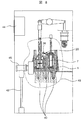
- the switchgear includes a bus 40 connected to the power system side for receiving power, a switch unit 46 connected to the bus 40 and having a switch, and power from the switch unit 46 on the load side.
- the cable 42 that distributes power to the cable, the cable head 45 that connects the switch unit 46 and the cable 42 according to the first embodiment, the operation unit 43 that operates the switch in the switch unit 46, and when an overcurrent is detected or a lightning strike And a control device room 44 that houses a protective relay that protects the device at times.
- the switch unit 46 is provided with a resin heat radiation fin for heat radiation having a height in the longitudinal direction of the fin and a height in the circumferential direction. Since the switch unit is the place where the heat generation is mainly high in the switch gear (panel), the cooling performance can be improved even when viewed as the entire switch gear.
- the switch unit which is the main part in the switch gear, can be miniaturized so that the entire switch gear can be miniaturized.
Landscapes
- High-Tension Arc-Extinguishing Switches Without Spraying Means (AREA)
- Gas-Insulated Switchgears (AREA)
- Thermally Actuated Switches (AREA)
- Patch Boards (AREA)
- Push-Button Switches (AREA)
Abstract
Description
1′ 樹脂放熱フィンの最高の高さ
1b 樹脂放熱フィンの底部
1b-in 樹脂放熱フィン内径側の曲率
1b-out フィンの径方向の高さが最も高い樹脂放熱フィン内径側の曲率
1d 樹脂放熱フィンの高さ
1m 放熱板
1t 樹脂放熱フィンの先端
1t-in 樹脂放熱フィンの先端の曲率
1t-out フィン高さが最も高い樹脂放熱フィン先端曲率
1w 樹脂放熱フィンの底部と真空容器外周間の樹脂の距離
2 絶縁樹脂
2p (樹脂表面の)平坦部
2w 樹脂表面の対称平坦部間の幅
3 ブッシング用固定電極
4 接地断路部可動導体
5 固定側導体
6 可動側導体
7 気中部
8 真空容器
9 中間固定電極
10 ばね接点
11、28 ケーブル用ブッシング
12、18 操作ロッド
13 母線用ブッシング
14 母線用ブッシング中心導体
15 ケーブル用ブッシング中心導体
16 固定側電極
17 可動側電極
19 接地側固定電極(ガイド)
20 フレキシブル導体
21 金属ケース
22 ベローズ
26 真空バルブ
27 接地断路部
29 固定側セラミックス絶縁筒
30 可動側セラミックス絶縁筒
31 固定側端板
32 可動側端板
33 ベローズシールド
34 固定側電界緩和シールド
35 可動側電界緩和シールド
40 母線
42 ケーブル
43 操作器
44 制御機器室
45 ケーブルヘッド
46 開閉器ユニット
Claims (10)
- 固定電極と、該固定電極に対向すると共に軸方向に動作して前記固定電極と接触または開離される可動電極と、前記一方の電極に接続されて、母線側と接続される母線側導体と、前記他方の電極に接続されて、負荷側と接続される負荷側導体と、を有する開閉器と、 該開閉器の周囲を覆う様に配置される絶縁樹脂と、を備え、
該絶縁樹脂は、該絶縁樹脂の外表面に、周方向にフィンを形成し、
前記開閉器の外周と、前記フィンの底部との距離は、周方向で略一定になる様に形成されることを特徴とする開閉器ユニット。 - 請求項1に記載の開閉器ユニットであって、
前記樹脂の外表面は平坦部を有しており、前記樹脂の先端が前記平坦部の面の内側に位置する様に形成されることを特徴とする開閉器ユニット。 - 請求項1または2に記載の開閉器ユニットであって、
前記フィンの径方向の高さが最も高いフィンの内径側の曲率は、該フィンの径方向の高さが最も高いフィン以外のフィンの内径側の曲率よりも大きく形成されることを特徴とする開閉器ユニット。 - 請求項1ないし3のいずれか一つに記載の開閉器ユニットであって、
前記開閉器は、前記固定電極及び前記可動電極を内部に有する真空容器を備える真空開閉器であり、
更に、1つまたは複数の他の固定電極と、該他の固定電極に対向すると共に軸方向に動作して前記他の固定電極と接触または開離される1つまたは複数の他の可動電極と、前記いずれかの他の電極に接続されて、母線側と接続される他の母線側導体と、前記いずれかの他の電極に接続されて、負荷側と接続される他の負荷側導体と、を有し、かつ、接地機能を有する開閉器を備えており、
該開閉器と前記真空開閉器は、導体を介して電気的に接続され、
前記絶縁樹脂は、前記開閉器及び前記真空開閉器の周囲を覆う様に配置され、
該絶縁樹脂の外表面に、周方向にフィンが形成され、該フィンの径方向の高さが最も高いフィンの内径側の曲率は、該フィンの径方向の高さが最も高いフィン以外のフィンの内径側の曲率よりも大きく形成されることを特徴とする開閉器ユニット。 - 請求項4に記載の開閉器ユニットであって、
前記開閉器及び前記真空開閉器は並んで配置され、
前記フィンの先端は、前記開閉器または前記真空開閉器を挟んで対向する一組の面を形成することを特徴とする開閉器ユニット。 - 請求項5に記載の開閉器ユニットであって、
前記フィンの先端は、更に前記一組の面に直交し、前記開閉器及び前記真空開閉器を挟んで対向する他の一組の面を形成することを特徴とする開閉器ユニット。 - 請求項4ないし6のいずれか一つに記載の開閉器ユニットであって、
更に前記いずれかの導体に接続されると共に、前記開閉器または真空開閉器の周囲を軸方向に亘って覆う放熱板を、前記絶縁樹脂の内部に配置し、前記フィンは前記放熱板の周囲を覆う様に形成されることを特徴とする開閉器ユニット。 - 請求項7に記載の開閉器ユニットであって、
前記フィンの高さは、前記放熱板のうちで最も前記絶縁樹脂の表面に近い前記放熱板の周囲で最も高く、該最も前記絶縁樹脂の表面に近い前記放熱板の周囲から軸方向に離れるにつれて、低くなる様な勾配を有することを特徴とする開閉器ユニット。 - 請求項7または8に記載の開閉器ユニットであって、
前記放熱板の先端は丸みを有していることを特徴とする開閉器ユニット。 - 請求項1ないし9のいずれか一つに記載の開閉器ユニットと、該開閉器ユニットに接続される母線及びケーブルと、前記いずれかの可動電極を駆動するための操作力を発生する操作器と、保護継電器を収納する制御機器室を有し、前記開閉器ユニット、前記母線、前記ケーブル、前記操作器及び前記制御機器室を内部に有する筺体を備えることを特徴とするスイッチギヤ。
Priority Applications (7)
| Application Number | Priority Date | Filing Date | Title |
|---|---|---|---|
| KR1020147033134A KR101694330B1 (ko) | 2012-05-29 | 2013-04-08 | 개폐기 유닛 또는 스위치 기어 |
| US14/404,081 US9437380B2 (en) | 2012-05-29 | 2013-04-08 | Switching unit or switching gear |
| CN201380027566.7A CN104335313A (zh) | 2012-05-29 | 2013-04-08 | 开闭器单元或开关设备 |
| EP13797146.1A EP2858082A4 (en) | 2012-05-29 | 2013-04-08 | SWITCHING UNIT OR SWITCHING DEVICE |
| JP2014518325A JP5868501B2 (ja) | 2012-05-29 | 2013-04-08 | 開閉器ユニットまたはスイッチギヤ |
| BR112014029749A BR112014029749A2 (pt) | 2012-05-29 | 2013-04-08 | unidade de comutação ou equipamento de comutação |
| IN9763DEN2014 IN2014DN09763A (ja) | 2012-05-29 | 2014-11-18 |
Applications Claiming Priority (2)
| Application Number | Priority Date | Filing Date | Title |
|---|---|---|---|
| JP2012-121480 | 2012-05-29 | ||
| JP2012121480 | 2012-05-29 |
Publications (1)
| Publication Number | Publication Date |
|---|---|
| WO2013179772A1 true WO2013179772A1 (ja) | 2013-12-05 |
Family
ID=49672980
Family Applications (1)
| Application Number | Title | Priority Date | Filing Date |
|---|---|---|---|
| PCT/JP2013/060580 WO2013179772A1 (ja) | 2012-05-29 | 2013-04-08 | 開閉器ユニットまたはスイッチギヤ |
Country Status (9)
| Country | Link |
|---|---|
| US (1) | US9437380B2 (ja) |
| EP (1) | EP2858082A4 (ja) |
| JP (1) | JP5868501B2 (ja) |
| KR (1) | KR101694330B1 (ja) |
| CN (1) | CN104335313A (ja) |
| BR (1) | BR112014029749A2 (ja) |
| IN (1) | IN2014DN09763A (ja) |
| TW (1) | TWI533344B (ja) |
| WO (1) | WO2013179772A1 (ja) |
Families Citing this family (6)
| Publication number | Priority date | Publication date | Assignee | Title |
|---|---|---|---|---|
| US9230750B2 (en) * | 2011-10-19 | 2016-01-05 | Mitsubishi Electric Corporation | Gas circuit breaker |
| CA2939796A1 (en) * | 2014-02-20 | 2015-08-27 | Cooper Technologies Company | Modular switchgear insulation system |
| USD800667S1 (en) | 2015-02-20 | 2017-10-24 | Cooper Technologies Company | Modular switchgear insulation device |
| CN205335165U (zh) * | 2015-08-31 | 2016-06-22 | 西门子公司 | 改进的断续器 |
| US10872739B2 (en) * | 2019-05-24 | 2020-12-22 | Frank P Stacom | Methods and systems for DC current interrupter based on thermionic arc extinction via anode ion depletion |
| CN112928644B (zh) * | 2021-01-31 | 2022-07-19 | 淄博天乙电气设备有限公司 | 一种有效防水防潮的配电柜 |
Citations (5)
| Publication number | Priority date | Publication date | Assignee | Title |
|---|---|---|---|---|
| JPS594141U (ja) * | 1982-07-01 | 1984-01-11 | 株式会社高岳製作所 | 固体絶縁真空開閉装置の冷却構造 |
| JPH02128335U (ja) * | 1989-03-29 | 1990-10-23 | ||
| JPH05303929A (ja) * | 1992-04-27 | 1993-11-16 | Mitsubishi Electric Corp | 固体絶縁開閉装置 |
| JP2001160342A (ja) | 1999-12-01 | 2001-06-12 | Toshiba Corp | スイッチギヤとその製造方法 |
| JP2012069345A (ja) * | 2010-09-22 | 2012-04-05 | Nissin Electric Co Ltd | 真空遮断器、及びスイッチギヤ |
Family Cites Families (11)
| Publication number | Priority date | Publication date | Assignee | Title |
|---|---|---|---|---|
| US3716098A (en) * | 1971-01-28 | 1973-02-13 | G Dotto | Automotive apparatus |
| US4123618A (en) * | 1976-06-09 | 1978-10-31 | Westinghouse Electric Corp. | Vapor-cooled terminal-bushings for oil-type circuit-interrupters |
| DE3327390A1 (de) * | 1983-07-29 | 1985-02-07 | Siemens AG, 1000 Berlin und 8000 München | Vakuumschaltroehre, insbesondere fuer einen niederspannungsschuetz |
| JPH08132711A (ja) * | 1994-11-07 | 1996-05-28 | Seiko Epson Corp | 印刷装置 |
| US5597992A (en) * | 1994-12-09 | 1997-01-28 | Cooper Industries, Inc. | Current interchange for vacuum capacitor switch |
| JPH10321096A (ja) * | 1997-05-23 | 1998-12-04 | Mitsubishi Electric Corp | 開閉器 |
| JP2001006502A (ja) * | 1999-06-18 | 2001-01-12 | Toshiba Corp | 真空遮断器 |
| JP2001028858A (ja) * | 1999-07-14 | 2001-01-30 | Mitsubishi Electric Corp | 回転電機用鋳造フレームおよび鋳造ブラケットならびにこれを備えた回転電機 |
| US6735068B1 (en) * | 2001-03-29 | 2004-05-11 | Mcgraw-Edison Company | Electrical apparatus employing one or more housing segments |
| JP2005074885A (ja) * | 2003-09-02 | 2005-03-24 | Seiko Epson Corp | インパクトドットヘッドの放熱器およびその製造方法、並びに、インパクトドットヘッドおよびプリンタ |
| JP2007073816A (ja) * | 2005-09-08 | 2007-03-22 | Nissan Motor Co Ltd | ダクト型冷却構造 |
-
2013
- 2013-04-08 BR BR112014029749A patent/BR112014029749A2/pt not_active IP Right Cessation
- 2013-04-08 EP EP13797146.1A patent/EP2858082A4/en not_active Withdrawn
- 2013-04-08 CN CN201380027566.7A patent/CN104335313A/zh active Pending
- 2013-04-08 JP JP2014518325A patent/JP5868501B2/ja not_active Expired - Fee Related
- 2013-04-08 KR KR1020147033134A patent/KR101694330B1/ko active IP Right Grant
- 2013-04-08 WO PCT/JP2013/060580 patent/WO2013179772A1/ja active Application Filing
- 2013-04-08 US US14/404,081 patent/US9437380B2/en not_active Expired - Fee Related
- 2013-04-16 TW TW102113460A patent/TWI533344B/zh not_active IP Right Cessation
-
2014
- 2014-11-18 IN IN9763DEN2014 patent/IN2014DN09763A/en unknown
Patent Citations (5)
| Publication number | Priority date | Publication date | Assignee | Title |
|---|---|---|---|---|
| JPS594141U (ja) * | 1982-07-01 | 1984-01-11 | 株式会社高岳製作所 | 固体絶縁真空開閉装置の冷却構造 |
| JPH02128335U (ja) * | 1989-03-29 | 1990-10-23 | ||
| JPH05303929A (ja) * | 1992-04-27 | 1993-11-16 | Mitsubishi Electric Corp | 固体絶縁開閉装置 |
| JP2001160342A (ja) | 1999-12-01 | 2001-06-12 | Toshiba Corp | スイッチギヤとその製造方法 |
| JP2012069345A (ja) * | 2010-09-22 | 2012-04-05 | Nissin Electric Co Ltd | 真空遮断器、及びスイッチギヤ |
Non-Patent Citations (1)
| Title |
|---|
| See also references of EP2858082A4 * |
Also Published As
| Publication number | Publication date |
|---|---|
| BR112014029749A2 (pt) | 2017-06-27 |
| KR20150003881A (ko) | 2015-01-09 |
| US20150102013A1 (en) | 2015-04-16 |
| JPWO2013179772A1 (ja) | 2016-01-18 |
| JP5868501B2 (ja) | 2016-02-24 |
| IN2014DN09763A (ja) | 2015-07-31 |
| TW201405614A (zh) | 2014-02-01 |
| KR101694330B1 (ko) | 2017-01-09 |
| EP2858082A4 (en) | 2016-02-24 |
| TWI533344B (zh) | 2016-05-11 |
| EP2858082A1 (en) | 2015-04-08 |
| CN104335313A (zh) | 2015-02-04 |
| US9437380B2 (en) | 2016-09-06 |
Similar Documents
| Publication | Publication Date | Title |
|---|---|---|
| JP5423657B2 (ja) | 開閉器ユニット及び開閉器ユニットを搭載するスイッチギヤ | |
| JP5868501B2 (ja) | 開閉器ユニットまたはスイッチギヤ | |
| JP4962616B2 (ja) | 真空遮断器及びそれを用いたガス絶縁開閉装置 | |
| JP4568765B2 (ja) | 真空スイッチギヤ | |
| EP2979292B1 (en) | A switch assembly, a switching device comprising a switch assembly, a switchgear comprising a switching device and a method for cooling | |
| JP4989794B1 (ja) | ガス遮断器 | |
| JP5565236B2 (ja) | 真空遮断器、及びスイッチギヤ | |
| JP5557794B2 (ja) | モールドスイッチ及びこれを搭載した装置 | |
| WO2023021842A1 (ja) | ガス絶縁開閉装置 | |
| CN109314010B (zh) | 具有双导电壳体的开关装置 | |
| EP2720244A1 (en) | A pole part of a circuit-breaker arrangement with a heat sink element | |
| EP4290547A1 (en) | Dielectric shielding heat sink | |
| JP5899028B2 (ja) | スイッチギヤ | |
| CN114203479A (zh) | 一种断路器结构 | |
| CA2881903A1 (en) | A circuit breaker | |
| CN114121527A (zh) | 用于开关设备的散热布置结构 |
Legal Events
| Date | Code | Title | Description |
|---|---|---|---|
| 121 | Ep: the epo has been informed by wipo that ep was designated in this application |
Ref document number: 13797146 Country of ref document: EP Kind code of ref document: A1 |
|
| ENP | Entry into the national phase |
Ref document number: 2014518325 Country of ref document: JP Kind code of ref document: A |
|
| ENP | Entry into the national phase |
Ref document number: 20147033134 Country of ref document: KR Kind code of ref document: A |
|
| REEP | Request for entry into the european phase |
Ref document number: 2013797146 Country of ref document: EP |
|
| WWE | Wipo information: entry into national phase |
Ref document number: 2013797146 Country of ref document: EP |
|
| WWE | Wipo information: entry into national phase |
Ref document number: 14404081 Country of ref document: US |
|
| NENP | Non-entry into the national phase |
Ref country code: DE |
|
| REG | Reference to national code |
Ref country code: BR Ref legal event code: B01A Ref document number: 112014029749 Country of ref document: BR |
|
| ENP | Entry into the national phase |
Ref document number: 112014029749 Country of ref document: BR Kind code of ref document: A2 Effective date: 20141128 |