以下、図面を参照して、本発明の実施の形態を説明する。なお、各図において同一又は相当する要素については同一の符号を付し、重複する説明を省略する。
Hereinafter, an embodiment of the present invention will be described with reference to the drawings. In addition, the same code | symbol is attached | subjected about the element which is the same or it corresponds in each figure, and the overlapping description is abbreviate | omitted.
本実施の形態では、本発明を、車両に搭載される接近車両検出装置(音源方位推定装置)に適用する。本実施の形態に係る接近車両検出装置は、複数のマイクロホン(集音器)で集音された各音信号に基づいて自車両に接近する車両を検出し(つまり、自車両周辺の他車両の走行音(検出対象の音源)の方位等を推定し)、接近車両の情報を運転支援装置に提供する。特に、本実施の形態では、接近車両を高精度に検出するために、環境に対応した適切なノイズモデルを生成し、そのノイズモデルを用いて集音器で集音された音信号からノイズを抑圧した音信号を用いる。本実施の形態には、ノイズモデル生成の構成が異なる5つの実施の形態があり、第1の実施の形態が基本となる形態であり、各実施の形態に機能を順次追加していく。
In the present embodiment, the present invention is applied to an approaching vehicle detection device (sound source direction estimation device) mounted on a vehicle. The approaching vehicle detection device according to the present embodiment detects a vehicle approaching the own vehicle based on each sound signal collected by a plurality of microphones (sound collectors) (that is, other vehicles around the own vehicle). The direction of the traveling sound (sound source to be detected) is estimated), and information on the approaching vehicle is provided to the driving support device. In particular, in the present embodiment, in order to detect an approaching vehicle with high accuracy, an appropriate noise model corresponding to the environment is generated, and noise is collected from the sound signal collected by the sound collector using the noise model. A suppressed sound signal is used. In this embodiment, there are five embodiments having different configurations for generating a noise model. The first embodiment is a basic embodiment, and functions are sequentially added to each embodiment.
なお、車両の走行音は、主として、ロードノイズ(タイヤ表面と路面との摩擦音)とパターンノイズ(タイヤ溝における空気の渦(圧縮/開放))である。この車両の走行音の周波数帯域は、実車実験等によって予め測定しておく。
Note that the running sound of the vehicle is mainly road noise (friction sound between the tire surface and the road surface) and pattern noise (air vortex (compression / release) in the tire groove). The frequency band of the running sound of the vehicle is measured in advance by an actual vehicle experiment or the like.
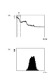
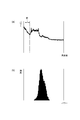
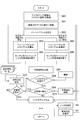
図1~図4を参照して、第1の実施の形態に係る接近車両検出装置1Aについて説明する。図1は、第1の実施の形態に係る接近車両検出装置の構成図である。図2は、走行音が観測されている時間帯のデータの一例であり、(a)がパワースペクトルであり、(b)がパワースペクトルのヒストグラムである。図3は、走行音が観測されていない時間帯のデータの一例であり、(a)がパワースペクトルであり、(b)がパワースペクトルのヒストグラムである。図4は、尺度母数の時間変化の一例である。
The approaching vehicle detection device 1A according to the first embodiment will be described with reference to FIGS. FIG. 1 is a configuration diagram of an approaching vehicle detection device according to the first embodiment. FIG. 2 is an example of data in a time zone in which traveling sound is observed, where (a) is a power spectrum and (b) is a histogram of the power spectrum. FIG. 3 is an example of data in a time zone in which no running sound is observed. (A) is a power spectrum, and (b) is a histogram of the power spectrum. FIG. 4 is an example of a time change of the scale parameter.
接近車両検出装置1Aは、ノイズモデル生成に適したタイミングを判断するために、マイクロホンで集音した音信号に検出対象の音源(車両の走行音)が含まれているか否かを判別し、ノイズモデルを生成可能なタイミング(区間)を判断する。そのために、接近車両検出装置1Aは、音信号のパワースペクトルを算出し、パワースペクトルのヒストグラム(確率密度分布)をガンマ分布フィッティングによって評価する。
The approaching vehicle detection device 1A determines whether or not the sound signal collected by the microphone includes a sound source to be detected (vehicle running sound) in order to determine timing suitable for noise model generation, and noise The timing (section) at which the model can be generated is determined. For this purpose, the approaching vehicle detection device 1A calculates the power spectrum of the sound signal and evaluates the power spectrum histogram (probability density distribution) by gamma distribution fitting.
接近車両検出装置1Aの構成を具体的に説明する前、図2、図3を参照して、音信号に走行音が含まれる場合と走行音が含まれない場合のパワースペクトル及びパワースペクトルのヒストグラムについて説明しておく。図2(a)には音信号に走行音が含まれている場合の音信号のパワースペクトル(各周波数に対するパワー(エネルギ))を示しており、図3(a)には音信号に走行音が含まれていない場合の音信号のパワースペクトルを示している。この各図(a)において、符号Rで示す区間が走行音の音成分が支配的に現れる周波数帯域である。また、図2(b)には音信号に走行音が含まれている場合の周波数帯域Rにおけるパワースペクトルのヒストグラム(各パワーの頻度)を示しており、図3(a)には音信号に走行音が含まれていない場合の周波数帯域Rにおけるパワースペクトルのヒストグラムを示している。
Before specifically describing the configuration of the approaching vehicle detection device 1A, referring to FIG. 2 and FIG. 3, the power spectrum when the sound signal includes the traveling sound and the histogram of the power spectrum when the traveling sound is not included I will explain. FIG. 2A shows the power spectrum (power (energy) for each frequency) of a sound signal when the sound signal includes a running sound. FIG. 3A shows the running signal in the sound signal. The power spectrum of the sound signal when no is included is shown. In each figure (a), the section indicated by symbol R is a frequency band in which the sound component of the running sound appears dominantly. FIG. 2B shows a histogram of the power spectrum (frequency of each power) in the frequency band R when the sound signal includes running sound, and FIG. 3A shows the sound signal. The histogram of the power spectrum in the frequency band R when the running sound is not included is shown.
図2(a)に示す周波数帯域Rにおけるパワー分布と図3(a)に示す周波数帯域Rにおけるパワー分布とを比較すると、音信号の中にノイズ成分(例えば、ホワイトノイズやピンクノイズ等の環境ノイズ)だけが含まれている場合と音情報の中にノイズ成分に加えて車両の走行音成分が含まれている場合とでパワー分布が異なっていることが判る。この違いは、図2(b)に示す周波数帯域Rにおけるパワースペクトルのヒストグラムと図3(b)に示す周波数帯域Rにおけるパワースペクトルのヒストグラムとを比較することにより、ヒストグラムの形状の違いから良く判る。このように、検出対象の走行音の周波数帯域Rにおけるパワースペクトルのヒストグラムの形状の変化から、音信号にノイズ成分だけが含まれているかあるいは音信号にノイズ成分に加えて検出対象の走行音成分が含まれているかを判別できる。
When the power distribution in the frequency band R shown in FIG. 2A and the power distribution in the frequency band R shown in FIG. 3A are compared, noise components (for example, white noise, pink noise, etc.) are included in the sound signal. It can be seen that the power distribution is different between the case where only (noise) is included and the case where the sound information includes the traveling sound component of the vehicle in addition to the noise component. This difference is well understood from the difference in the shape of the histogram by comparing the histogram of the power spectrum in the frequency band R shown in FIG. 2B and the histogram of the power spectrum in the frequency band R shown in FIG. . As described above, from the change in the shape of the histogram of the power spectrum in the frequency band R of the traveling sound to be detected, the sound signal contains only the noise component or the traveling sound component to be detected in addition to the noise component in the sound signal Can be determined.
また、ノイズモデルに基づいてノイズ成分が抑圧された音信号を用いて走行音を高精度に検出するためには、走行音が存在しない環境で集音された音信号からノイズモデルを生成する必要がある。ちなみに、走行音が存在する環境で集音された音信号からノイズモデルを生成した場合、ノイズモデルの中に走行音成分も含まれるので、そのノイズモデルを用いると音信号の中から必要な音成分まで抑圧してしまう。
In addition, in order to detect a running sound with high accuracy using a sound signal whose noise component is suppressed based on the noise model, it is necessary to generate a noise model from a sound signal collected in an environment where no running sound exists. There is. By the way, when a noise model is generated from a sound signal collected in an environment where traveling sound exists, the noise model also includes a traveling sound component. It suppresses even the component.
そこで、パワースペクトルのヒストグラムの形状を評価することによって、走行音が存在しない環境かあるいは走行音が存在する環境かを判定し、走行音が存在しない環境であるタイミング(区間)を検出する。このタイミングで集音されている音信号を用いてノイズモデルを生成することにより、ノイズ成分だけが含まれている音信号からノイズモデルを生成できる。
Therefore, by evaluating the shape of the histogram of the power spectrum, it is determined whether the environment has no running sound or the running sound, and a timing (section) that is an environment in which no running sound exists is detected. By generating a noise model using a sound signal collected at this timing, it is possible to generate a noise model from a sound signal containing only noise components.
ヒストグラムの形状を評価するために、車両走行中の様々な環境で集音した音信号のデータ(走行音を含むデータと走行音を含まないデータ)を各種手法に適用した結果、ガンマ分布フィッティングによる尺度母数を特徴量とした場合が最も有効であった。図4には、実線L1で車両走行中に集音した音信号のパワースペクトルから求められた尺度母数の時間変化の一例を示している。実線L1の変化から判るように、走行音が観測されない時間帯では尺度母数は0近傍になるが、走行音が観測される時間帯T1,T2,T3,T4では尺度母数が顕著に大きくなる。このように、尺度母数の大きさから、走行音が存在する環境と走行音が存在しない環境とを判別できる。
In order to evaluate the shape of the histogram, as a result of applying the sound signal data collected in various environments while the vehicle is running (data containing running sound and data not containing running sound) to various methods, the result of gamma distribution fitting The case where the scale parameter was used as the feature value was the most effective. FIG. 4 shows an example of the time change of the scale parameter obtained from the power spectrum of the sound signal collected while the vehicle is traveling on the solid line L1. As can be seen from the change in the solid line L1, the scale parameter is close to 0 in the time zone when no running sound is observed, but the scale parameter is significantly larger in the time zones T1, T2, T3, and T4 where the running sound is observed. Become. In this way, it is possible to discriminate between the environment where the running sound exists and the environment where the running sound does not exist from the magnitude of the scale parameter.
そこで、第1の実施の形態では、パワースペクトルのヒストグラムを評価するために、ガンマ分布フィッティングを用いて、ガンマ分布の形状母数を求め、その形状係数から尺度母数を求め、尺度母数を評価の特徴量とする。ガンマ分布は、連続確率分布の一種であり、その性質が形状分布と尺度分布の2つのパラメータで特徴付けられる。なお、ガンマ分布フィッティングを用いる場合、パワースペクトルから形状母数や尺度母数を直接求めることができるので、パワースペクトルのヒストグラムを算出してガンマ分布フィッティングを行ってもよいしあるいはヒストグラムを算出することなくガンマ分布フィッティングを行ってもよい。
Therefore, in the first embodiment, in order to evaluate the histogram of the power spectrum, the shape parameter of the gamma distribution is obtained using gamma distribution fitting, the scale parameter is obtained from the shape coefficient, and the scale parameter is obtained. The feature amount of the evaluation. The gamma distribution is a kind of continuous probability distribution, and its characteristics are characterized by two parameters, a shape distribution and a scale distribution. When using gamma distribution fitting, the shape parameter and scale parameter can be obtained directly from the power spectrum, so the histogram of the power spectrum may be calculated and the gamma distribution fitting may be performed, or the histogram may be calculated. Alternatively, gamma distribution fitting may be performed.
それでは、接近車両検出装置1Aの構成を説明する。接近車両検出装置1Aは、マイクロホンアレイ10、デジタル信号変換器20及びECU[Electronic Control Unit]30A(ノイズモデル生成部31A、ノイズ抑圧器32、音源方位推定器33)を備えている。
Now, the configuration of the approaching vehicle detection device 1A will be described. The approaching vehicle detection device 1A includes a microphone array 10, a digital signal converter 20, and an ECU [Electronic Control Unit] 30A (a noise model generation unit 31A, a noise suppressor 32, and a sound source direction estimator 33).
マイクロホンアレイ10は、左側マイクロホンユニット11と右側マイクロホンユニット12を有している。左側マイクロホンユニット11と右側マイクロホンユニット12とは、車両の前端部における同じ高さ位置に車幅方向(左右方向)の左側と右側に配置される。左側マイクロホンユニット11は、第1マイクロホン11aと第2マイクロホン11bを有している。例えば、第1マイクロホン11aは車幅方向の左側の外側に配置され、第2マイクロホン11bは第1マイクロホン11bから所定の間隔をあけて車両中心側に配置される。右側マイクロホンユニット12は、第3マイクロホン12aと第4マイクロホン12bを有している。例えば、第4マイクロホン12bは車幅方向の右側の外側に配置され、第3マイクロホン12aは第4マイクロホン12bから所定の間隔をあけて車両中心側に配置される。各マイクロホン11a,11b,12a,12bは、音響電気変換器であり、車外の周囲の音をアナログの電気信号に変換し、その電気信号(音信号)をデジタル信号変換器20に出力する。なお、本実施の形態では、マイクロホン11a,11b,12a,12bが請求の範囲に記載する集音器に相当する。
The microphone array 10 has a left microphone unit 11 and a right microphone unit 12. The left microphone unit 11 and the right microphone unit 12 are arranged on the left and right sides in the vehicle width direction (left-right direction) at the same height position at the front end of the vehicle. The left microphone unit 11 includes a first microphone 11a and a second microphone 11b. For example, the first microphone 11a is disposed outside the left side in the vehicle width direction, and the second microphone 11b is disposed on the vehicle center side with a predetermined distance from the first microphone 11b. The right microphone unit 12 includes a third microphone 12a and a fourth microphone 12b. For example, the fourth microphone 12b is disposed outside the right side in the vehicle width direction, and the third microphone 12a is disposed on the vehicle center side at a predetermined interval from the fourth microphone 12b. Each of the microphones 11 a, 11 b, 12 a, and 12 b is an acoustoelectric converter that converts a sound outside the vehicle into an analog electric signal and outputs the electric signal (sound signal) to the digital signal converter 20. In the present embodiment, the microphones 11a, 11b, 12a, and 12b correspond to the sound collectors described in the claims.
デジタル信号変換器20では、マイクロホン11a,11b,12a,12b毎にアナログの音信号(電気信号)を入力すると、その各音信号をデジタルの音信号(電気信号)にそれぞれ変換する。そして、デジタル信号変換器20では、マイクロホン毎のデジタルの音信号(電気信号)をECU30Aにそれぞれ出力する。
In the digital signal converter 20, when an analog sound signal (electric signal) is input to each of the microphones 11a, 11b, 12a, and 12b, each sound signal is converted into a digital sound signal (electric signal). The digital signal converter 20 outputs a digital sound signal (electric signal) for each microphone to the ECU 30A.
ECU30Aは、CPU[Central Processing Unit]、ROM[Read Only Memory]、RAM[Random Access Memory]等からなる電子制御ユニットであり、接近車両検出装置1Aを統括制御する。ECU30Aには、ノイズモデル生成部31A(パワースペクトル算出器31a、ヒストグラム算出器31b、尺度母数算出器31c、ノイズモデル生成可否判定器31d、ノイズモデル生成器31e)、ノイズ抑圧器32、音源方位推定器33が構成される。ECU30Aでは、デジタル信号変換器20からマイクロホン毎の音信号(デジタルの電気信号)をそれぞれ入力する。
The ECU 30A is an electronic control unit including a CPU [Central Processing Unit], ROM [Read Only Memory], RAM [Random Access Memory], and the like, and comprehensively controls the approaching vehicle detection device 1A. The ECU 30A includes a noise model generation unit 31A (power spectrum calculator 31a, histogram calculator 31b, scale parameter calculator 31c, noise model generation availability determination unit 31d, noise model generator 31e), noise suppressor 32, sound source direction. An estimator 33 is configured. In the ECU 30A, a sound signal (digital electric signal) for each microphone is input from the digital signal converter 20.
なお、第1の実施の形態では、パワースペクトル算出器31aが請求の範囲に記載するパワースペクトル取得部に相当し、尺度母数算出器31cが請求の範囲に記載する尺度母数算出部に相当し、ノイズモデル生成可否判定器31dが請求の範囲に記載する判定部に相当し、ノイズモデル生成器31eが請求の範囲に記載するノイズモデル生成部に相当し、ノイズ抑圧器32が請求の範囲に記載するノイズ抑圧部に相当する。
In the first embodiment, the power spectrum calculator 31a corresponds to the power spectrum acquisition unit described in the claims, and the scale parameter calculator 31c corresponds to the scale parameter calculation unit described in the claims. The noise model generation availability determination unit 31d corresponds to the determination unit described in the claims, the noise model generator 31e corresponds to the noise model generation unit described in the claims, and the noise suppressor 32 corresponds to the claims. This corresponds to the noise suppression unit described in (1).
パワースペクトル算出器31aでは、デジタル信号変換器20からのデジタルの音信号を用いて、音信号に対してFFT[Fast Fourier Transform](高速フーリエ変換)を行い、音信号のパワースペクトル(周波数毎のパワー(エネルギ))を算出する。ここでは、4個のマイクロホン11a,11b,12a,12bの音信号のうちの任意の1個のマイクロホンの音信号を用いてもよいし、あるいは、4個のマイクロホン11a,11b,12a,12bの音信号のうちの複数のマイクロホン(例えば、左側と右側で対応する2個のマイクロホン、4個全てのマイクロホン)の音信号を平均化した音信号でもよい。
The power spectrum calculator 31a performs an FFT [Fast Fourier Transform] (fast Fourier transform) on the sound signal using the digital sound signal from the digital signal converter 20, and the power spectrum of the sound signal (for each frequency). Power (energy) is calculated. Here, the sound signal of any one of the sound signals of the four microphones 11a, 11b, 12a, and 12b may be used, or the sound signals of the four microphones 11a, 11b, 12a, and 12b may be used. A sound signal obtained by averaging sound signals of a plurality of microphones (for example, two microphones corresponding to the left side and the right side, and all four microphones) may be used.
ヒストグラム算出器31bでは、パワースペクトル算出器31aで算出したパワースペクトルから、走行音が支配的に含まれる周波数帯域におけるパワースペクトルのヒストグラムを算出する。
The histogram calculator 31b calculates a histogram of the power spectrum in the frequency band in which the running sound is dominantly included from the power spectrum calculated by the power spectrum calculator 31a.
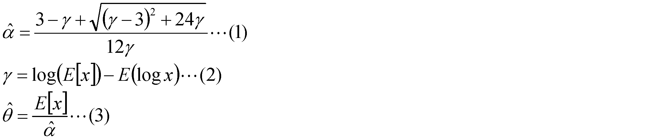
尺度母数算出器31cでは、走行音が支配的に含まれる周波数帯域におけるパワースペクトルのデータを用いて、ガンマ分布フィッティングを行い、尺度母数を算出する。具体的には、式(1)により、形状母数αの推定値を算出する。式(1)におけるγは、走行音が支配的な周波数帯域における各周波数のパワーのデータ列{x:x1,x2,・・・,xN}を用いて、式(2)により算出できる。さらに、形状母数αの推定値とデータ列{x:x1,x2,・・・,xN}を用いて、式(3)により、尺度母数θの推定値を算出する。
The scale parameter calculator 31c performs gamma distribution fitting using the power spectrum data in the frequency band in which the running sound is predominantly included, and calculates the scale parameter. Specifically, the estimated value of the shape parameter α is calculated by the equation (1). Γ in Expression (1) can be calculated by Expression (2) using a power data sequence {x: x1, x2,..., XN} of each frequency in a frequency band in which traveling sound is dominant. Further, using the estimated value of the shape parameter α and the data string {x: x1, x2,..., XN}, the estimated value of the scale parameter θ is calculated by Equation (3).
ノイズモデル生成可否判定器31dでは、尺度母数算出器31cで算出した尺度母数と閾値とを比較し、尺度母数が閾値以上の場合(尺度母数が大きく、音信号に走行音が含まれていると判断できる場合)にはノイズモデル生成不可と判定し、尺度母数が閾値未満の場合(尺度母数が小さく、音信号に走行音が含まれていないと判断できる場合)にはノイズモデル生成可と判定する。この閾値は、音信号の中に走行音が含まれているか否かを尺度母数の大きさに基づいて判定するための閾値であり、実験等によって予め設定される。
In the noise model generation possibility determination unit 31d, the scale parameter calculated by the scale parameter calculator 31c is compared with a threshold value. When the scale parameter is equal to or greater than the threshold value (the scale parameter is large and the running signal is included in the sound signal). If the scale parameter is less than the threshold (if the scale parameter is small and it can be determined that the sound signal does not contain running sound) It is determined that a noise model can be generated. This threshold value is a threshold value for determining whether or not a running sound is included in the sound signal based on the magnitude of the scale parameter, and is set in advance by an experiment or the like.
ノイズモデル生成器31eでは、ノイズモデル生成可否判定器31dでノイズモデル生成可と判定した場合、デジタル信号変換器20からのデジタルの音信号を用いてノイズモデルを生成する。この生成方法としては、従来の方法を適用し、例えば、4個のマイクロホン11a,11b,12a,12bの音信号のうちの任意の1個のマイクロホンの音信号をそのままノイズモデルとしたり、4個のマイクロホン11a,11b,12a,12bの音信号のうちの複数のマイクロホンの音信号を平均化した音信号をノイズモデルとする。
The noise model generator 31e generates a noise model using the digital sound signal from the digital signal converter 20 when the noise model generation availability determination unit 31d determines that the noise model can be generated. As this generation method, a conventional method is applied. For example, the sound signal of any one of the four microphones 11a, 11b, 12a, and 12b is directly used as a noise model, or four A sound signal obtained by averaging sound signals of a plurality of microphones among sound signals of the microphones 11a, 11b, 12a, and 12b is used as a noise model.
ノイズ抑圧器32では、ノイズモデルを用いて、デジタル信号変換器20からのマイクロホン毎のデジタルの音信号からノイズ成分をそれぞれ抑圧する。この抑圧方法としては、従来の方法を適用し、例えば、音信号においてノイズモデルよりも大きな値を持つ区間を抽出し、その区間の音信号だけを音源方位推定器33で用いるようにする。ここでは、ノイズモデル生成器31eで既にノイズモデルを生成している場合にはそのノイズモデルを用い、ノイズモデル生成器31eでノイズモデルを生成していない場合には予め用意されているノイズモデルを用いる。予め用意されているノイズモデルは、実験等によって予め生成されたものである。
The noise suppressor 32 suppresses noise components from the digital sound signal for each microphone from the digital signal converter 20 using a noise model. As this suppression method, a conventional method is applied. For example, a section having a larger value than the noise model is extracted from the sound signal, and only the sound signal in the section is used by the sound source direction estimator 33. Here, when the noise model is already generated by the noise model generator 31e, the noise model is used. When the noise model is not generated by the noise model generator 31e, a noise model prepared in advance is used. Use. The noise model prepared in advance is generated in advance by experiments or the like.
音源方位推定器33では、ノイズ抑圧器32でノイズ成分を抑圧した各マイクロホン11a,11b,12a,12bの音信号を用いて、検出対象の音源(走行音(ひいては、自車両に接近する車両))が存在するかを判定し、音源が存在する場合にはその音源の方向や距離等を推定する。この推定方法としては、従来の方法を適用し、例えば、CSP[Cross power Spectrum Phase analysis]法がある。CSP法は、左右のマイクロホン対で集音された各音信号に対して周波数領域でのマッチングを行い、相互相関値(CSP係数)を求め、相互相関値が閾値以上の場合には音源が存在すると判断し、音源が存在する場合には相互相関値が最大となる到達時間差から車両の方向や距離等を求める。
The sound source direction estimator 33 uses the sound signals of the microphones 11a, 11b, 12a, and 12b whose noise components are suppressed by the noise suppressor 32 to detect the sound source to be detected (running sound (and thus a vehicle approaching the host vehicle)). ) Is present, and if a sound source is present, the direction and distance of the sound source are estimated. As this estimation method, a conventional method is applied, for example, CSP [Cross power Spectrum Phase analysis] method. In the CSP method, matching is performed in the frequency domain for each sound signal collected by a pair of left and right microphones to obtain a cross-correlation value (CSP coefficient). If the cross-correlation value is equal to or greater than a threshold, a sound source exists. If the sound source is present, the direction, distance, etc. of the vehicle are obtained from the arrival time difference that maximizes the cross-correlation value.
ECU30Aでは、音源方位推定器33の検出対象の音源の検出結果に基づいて接近車両情報を生成し、接近車両情報を運転支援装置2に出力する。接近車両情報としては、例えば、接近車両の有無、接近車両が存在する場合には方向、距離の情報である。
The ECU 30A generates approaching vehicle information based on the detection result of the sound source to be detected by the sound source direction estimator 33, and outputs the approaching vehicle information to the driving support device 2. The approaching vehicle information includes, for example, the presence / absence of an approaching vehicle, and information on a direction and a distance when an approaching vehicle exists.
運転支援装置2は、運転者に対して各種運転支援する装置である。特に、運転支援装置2では、一定時間毎に、接近車両検出装置1Aから接近車両情報を入力すると、接近車両に関する運転支援を実施する。例えば、自車両に対して接近する車両が存在する場合、自車両に対する接近車両の衝突の可能性を判定し、衝突の可能性があると判定したときには運転者に対して警報を出力したり、接近車両の情報を提供し、更に、衝突の可能性が高まった場合には自動ブレーキや自動操舵等の車両制御を行う。
The driving support device 2 is a device that supports various driving operations for the driver. In particular, in the driving assistance device 2, when approaching vehicle information is input from the approaching vehicle detection device 1A at regular intervals, driving assistance regarding the approaching vehicle is performed. For example, if there is a vehicle approaching the host vehicle, determine the possibility of a collision of the approaching vehicle to the host vehicle, and output a warning to the driver when it is determined that there is a possibility of a collision, Information on approaching vehicles is provided, and when the possibility of collision increases, vehicle control such as automatic braking and automatic steering is performed.
図1~図4を参照して、接近車両検出装置1Aの動作について説明する。ここでは、図5のフローチャートに沿って接近車両検出装置1Aにおける全体の動作を説明し、その後に、図6のフローチャートに沿って接近車両検出装置1Aにおけるノイズモデル生成に関する動作を説明する。図5は、本実施の形態に係る接近車両検出装置における全体の動作の流れを示すフローチャートである。図6は、第1の実施の形態に係るノイズモデル生成に関する動作の流れを示すフローチャートである。
The operation of the approaching vehicle detection device 1A will be described with reference to FIGS. Here, the overall operation of the approaching vehicle detection device 1A will be described along the flowchart of FIG. 5, and thereafter, the operation related to the noise model generation in the approaching vehicle detection device 1A will be described along the flowchart of FIG. FIG. 5 is a flowchart showing an overall operation flow in the approaching vehicle detection device according to the present embodiment. FIG. 6 is a flowchart showing a flow of operations related to noise model generation according to the first embodiment.
まず、接近車両検出装置1Aにおける全体の動作を説明する。車両状態や交通環境に基づいて、接近車両検出装置1Aのシステム作動論理を判断し(S1)、接近車両検出装置1Aを作動させるか否かを判定する(S2)。このシステム作動論理は、接近車両検出装置1Aを作動させる必要があるか否かを判断する条件であり、例えば、車両状態として車速が所定車速以上、あるいは以下であるという条件、交通環境としては自車両の前方に交差点が存在するという条件がある。なお、接近車両検出装置1Aを統括管理する上位の装置が存在し、この上位の装置(特に、ECU)で、S1、S2の各処理を行い、接近車両検出装置1Aを作動させると判定した場合には接近車両検出装置1Aを作動させる。
First, the overall operation of the approaching vehicle detection device 1A will be described. Based on the vehicle state and traffic environment, the system operation logic of the approaching vehicle detection device 1A is determined (S1), and it is determined whether or not the approaching vehicle detection device 1A is to be operated (S2). This system operation logic is a condition for determining whether or not the approaching vehicle detection device 1A needs to be operated. For example, the vehicle condition is that the vehicle speed is equal to or higher than a predetermined vehicle speed, and the traffic environment is There is a condition that there is an intersection in front of the vehicle. When there is a higher-level device that manages the approaching vehicle detection device 1A in an integrated manner, and it is determined that the higher-level device (particularly the ECU) performs the processes of S1 and S2 to activate the approaching vehicle detection device 1A. The approaching vehicle detection device 1A is activated.
S2にて接近車両検出装置1Aを作動させると判定した場合、接近車両検出装置1Aが作動される。接近車両検出装置1Aが作動中、以下の動作を繰り返し行う。接近車両検出装置1Aでは、マイクロホンアレイ10の各マイクロホン11a,11b,12a,12bで車外の周囲の音をそれぞれ集音し、その各マイクロホン11a,11b,12a,12bの音信号をデジタル信号変換器20でデジタル信号にそれぞれ変換する。接近車両検出装置1AのECU30A(ノイズモデル生成部31A)では、デジタル信号変換器20で変換された音信号を用いて、その音信号の中に検出対象である走行音が存在するか否かを推定し(S3)、その推定よりノイズモデル生成が可能か否かを判定する(S4)。接近車両検出装置1AのECU30Aでは、S4にてノイズモデルを生成可能と判定した場合には音信号を用いてノイズモデルを生成し(S5)。S4にてノイズモデルを生成不可と判定した場合にはノイズモデルを生成しない。このS3~S5の動作については、後で詳細に説明する。
If it is determined in S2 that the approaching vehicle detection device 1A is to be operated, the approaching vehicle detection device 1A is operated. While the approaching vehicle detection device 1A is operating, the following operations are repeated. In the approaching vehicle detection device 1A, ambient sounds outside the vehicle are collected by the microphones 11a, 11b, 12a, and 12b of the microphone array 10, and the sound signals of the microphones 11a, 11b, 12a, and 12b are converted into digital signal converters. 20 to convert each into a digital signal. The ECU 30A (noise model generation unit 31A) of the approaching vehicle detection device 1A uses the sound signal converted by the digital signal converter 20 to determine whether or not a running sound as a detection target exists in the sound signal. It is estimated (S3), and it is determined whether the noise model can be generated based on the estimation (S4). The ECU 30A of the approaching vehicle detection device 1A generates a noise model using a sound signal when it is determined in S4 that a noise model can be generated (S5). If it is determined in S4 that a noise model cannot be generated, no noise model is generated. The operations of S3 to S5 will be described later in detail.
また、接近車両検出装置1AのECU30A(ノイズ抑圧器32)では、S5で生成されたノイズモデルがある場合には、そのノイズモデルを用いて、デジタル信号変換器20で変換された各マイクロホンの音信号からノイズ成分をそれぞれ抑圧する(S6)。一方、S5で生成されたノイズモデルがない場合、予め用意されているノイズモデルを用いて、デジタル信号変換器20で変換された各マイクロホンの音信号からノイズ成分をそれぞれ抑圧する(S6)。より詳細には、ノイズモデルがない場合とは、ノイズモデルの生成が一度も実行されていない場合の他にも、設定された所定時間前から現時点までの間にノイズモデルの生成が実行されていない場合などが相当する。そして、ECU30A(音源方位推定器33)では、S6でノイズ成分が抑圧された各マイクロホンの音信号を用いて、検出対象の音源(自車両に接近する車両の走行音)が存在するかを判定し、検出対象の音源が存在する場合にはその検出対象の音源の方向や距離等を推定する(S7)。そして、ECU30Aでは、その音源の検出結果に基づいて接近車両情報を生成し、接近車両情報を運転支援装置2に出力する。なお、S6ではノイズモデルがまだ生成されていない場合には予め用意されているノイズモデルを用いてノイズ抑圧を行ったが、ノイズモデルがまだ生成されていない場合には、ノイズ抑圧はしないまま、検出対象の音源が存在するかを判定する構成としてもよい。
Further, in the ECU 30A (noise suppressor 32) of the approaching vehicle detection device 1A, if there is a noise model generated in S5, the sound of each microphone converted by the digital signal converter 20 using the noise model is used. Each noise component is suppressed from the signal (S6). On the other hand, if there is no noise model generated in S5, the noise component is suppressed from the sound signal of each microphone converted by the digital signal converter 20 using a noise model prepared in advance (S6). More specifically, in the case where there is no noise model, the generation of the noise model is executed between the predetermined time and the current time, in addition to the case where the generation of the noise model has never been executed. This is the case when there is no such thing. Then, the ECU 30A (sound source direction estimator 33) uses the sound signal of each microphone whose noise component is suppressed in S6 to determine whether there is a sound source to be detected (a running sound of a vehicle approaching the host vehicle). If there is a sound source to be detected, the direction and distance of the sound source to be detected is estimated (S7). Then, the ECU 30A generates approaching vehicle information based on the detection result of the sound source, and outputs the approaching vehicle information to the driving support device 2. In S6, when a noise model has not yet been generated, noise suppression is performed using a prepared noise model. However, when a noise model has not yet been generated, noise suppression is not performed. It is good also as a structure which determines whether the sound source of a detection target exists.
次に、接近車両検出装置1Aにおけるノイズモデル生成に関する動作について説明する。マイクロホンアレイ10の各マイクロホン11a,11b,12a,12bでは、車外の周囲の音をそれぞれ集音し、アナログの音信号を取得する(S10)。デジタル信号変換器20では、各マイクロホン11a,11b,12a,12bのアナログの音信号をデジタルの音信号にそれぞれ変換する(S11)。
Next, operations relating to noise model generation in the approaching vehicle detection device 1A will be described. Each microphone 11a, 11b, 12a, 12b of the microphone array 10 collects sounds outside the vehicle and acquires an analog sound signal (S10). The digital signal converter 20 converts the analog sound signals of the microphones 11a, 11b, 12a, and 12b into digital sound signals, respectively (S11).
ECU30A(パワースペクトル算出器31a)では、S11でデジタル信号に変換された音信号に対してFFTを行い、音信号のパワースペクトルを算出する(S12)。そして、ECU30A(ヒストグラム算出器31b)では、そのパワースペクトルから、走行音が支配的な周波数帯域におけるパワースペクトルのヒストグラムを算出する(S13)。さらに、ECU30A(尺度母数算出器31c)では、走行音が支配的な周波数帯域におけるパワースペクトルのデータを用いて、ガンマ分布フィッティングを行い、尺度母数を算出する(S14)。
ECU 30A (power spectrum calculator 31a) performs FFT on the sound signal converted into the digital signal in S11 to calculate the power spectrum of the sound signal (S12). Then, the ECU 30A (histogram calculator 31b) calculates a histogram of the power spectrum in the frequency band where the running sound is dominant from the power spectrum (S13). Further, the ECU 30A (scale parameter calculator 31c) performs gamma distribution fitting using the data of the power spectrum in the frequency band where the running sound is dominant, and calculates the scale parameter (S14).
そして、ECU30A(ノイズモデル生成可否判定器31d)では、その尺度母数と閾値とを比較し、ノイズモデル生成が可能か否かを判定する(S15)。S15にて尺度母数が閾値以上の場合にはノイズモデル生成不可と判定し、ノイズモデルを生成しない。一方、S15にて尺度母数が閾値未満の場合にはノイズモデル生成可と判定し、ECU30A(ノイズモデル生成器31e)では、S11でデジタル信号に変換された音信号を用いてノイズモデルを生成する(S16)。
The ECU 30A (noise model generation availability determination unit 31d) compares the scale parameter with a threshold value to determine whether noise model generation is possible (S15). If the scale parameter is greater than or equal to the threshold value in S15, it is determined that the noise model cannot be generated, and no noise model is generated. On the other hand, if the scale parameter is less than the threshold value in S15, it is determined that a noise model can be generated, and the ECU 30A (noise model generator 31e) generates a noise model using the sound signal converted into a digital signal in S11. (S16).
この接近車両検出装置1Aによれば、音信号のパワースペクトルのヒストグラムを評価することにより音信号の中に走行音(検出対象の音源)が含まれているか否かを高精度に判定できるので、ノイズモデルを生成するための適切なタイミングを判断でき、各環境に対して適応的にノイズモデルを生成することができる。この生成されたノイズモデルを用いることにより、音信号からのノイズ成分の抑圧効果が向上する。このノイズ成分が抑圧された音信号を用いることにより、接近車両を高精度に検出することができる。さらに、接近車両検出装置1Aによれば、ガンマ分布フィッティングによる尺度母数を用いることにより、パワースペクトルのヒストグラムを高精度に評価することができる。
According to this approaching vehicle detection device 1A, by evaluating the histogram of the power spectrum of the sound signal, it can be determined with high accuracy whether or not a running sound (sound source to be detected) is included in the sound signal. Appropriate timing for generating a noise model can be determined, and a noise model can be generated adaptively for each environment. By using the generated noise model, the noise component suppression effect from the sound signal is improved. By using the sound signal in which the noise component is suppressed, the approaching vehicle can be detected with high accuracy. Furthermore, according to the approaching vehicle detection device 1A, the histogram of the power spectrum can be evaluated with high accuracy by using the scale parameter by gamma distribution fitting.
図7、図8を参照して、第2の実施の形態に係る接近車両検出装置1Bについて説明する。図7は、第2の実施の形態に係る接近車両検出装置の構成図である。図8は、走行音が観測される周波数帯域での尺度母数と走行音が観測されない周波数帯域での尺度母数の時間変化の一例である。
Referring to FIGS. 7 and 8, an approaching vehicle detection device 1B according to the second embodiment will be described. FIG. 7 is a configuration diagram of the approaching vehicle detection device according to the second embodiment. FIG. 8 is an example of the time variation of the scale parameter in the frequency band where the running sound is observed and the scale parameter in the frequency band where the running sound is not observed.
接近車両検出装置1Bは、第1の実施の形態に係る接近車両検出装置1Aと比較すると、集音される音信号における2つの周波数帯域の特性からマイクロホンで集音した音信号に走行音が含まれているか否かを判別する機能を有している。そのために、接近車両検出装置1Bは、音信号のパワースペクトルを算出し、走行音(検出対象の音源)が含まれる第1周波数帯域のパワースペクトルのヒストグラムと走行音が含まれない第2周波数帯域のパワースペクトルのヒストグラムとをガンマ分布フィッティングによって評価する。
Compared to the approaching vehicle detection device 1A according to the first embodiment, the approaching vehicle detection device 1B includes traveling sound in the sound signal collected by the microphone from the characteristics of the two frequency bands in the collected sound signal. It has a function of determining whether or not Therefore, the approaching vehicle detection device 1B calculates the power spectrum of the sound signal, the histogram of the power spectrum of the first frequency band including the traveling sound (sound source to be detected), and the second frequency band not including the traveling sound. The power spectrum histogram is evaluated by gamma distribution fitting.
接近車両検出装置1Bの構成を具体的に説明する前に、図8を参照して、走行音(検出対象の音源)が含まれる第1周波数帯域の尺度母数と走行音が含まれない第2周波数帯域の尺度母数との関係について説明しておく。走行音が存在しない環境では、ホワイトノイズやピンクノイズ等のノイズ環境となるので、全周波数帯域においてパワー分布に連続性がある。一方、走行音が存在する環境では、走行音を含む周波数帯域ではパワー分布が変化するので、走行音を含む周波数帯域とそれ以外の周波数帯域との間で連続性がなくなる。したがって、この2つの周波数帯域のパワースペクトルのヒストグラムを比較することにより、走行音が存在しない環境(ノイズモデルを生成するのに適した環境)かあるいは走行音が存在する環境(ノイズモデルを生成するのに適しない環境)かを高精度に判別できる。
Before specifically describing the configuration of the approaching vehicle detection device 1B, referring to FIG. 8, the scale parameter of the first frequency band including the traveling sound (the sound source to be detected) and the traveling sound are not included. The relationship with the scale parameter of the two frequency bands will be described. In an environment where there is no traveling sound, a noise environment such as white noise or pink noise is generated, and thus the power distribution is continuous in the entire frequency band. On the other hand, in an environment where traveling sound exists, the power distribution changes in the frequency band including the traveling sound, so that there is no continuity between the frequency band including the traveling sound and the other frequency bands. Therefore, by comparing the histograms of the power spectra of the two frequency bands, an environment where no running sound exists (an environment suitable for generating a noise model) or an environment where running noise exists (a noise model is generated). Can be determined with high accuracy.
そこで、走行音を含む周波数帯域のパワースペクトルのヒストグラムと走行音を含まない周波数帯域のパワースペクトルのヒストグラムとを比較評価することによって、走行音が存在しない環境かあるいは走行音が存在する環境かを判定し、走行音が存在しない環境であるタイミング(区間)を検出する。この評価には、第1の実施の形態でも説明したように、ガンマ分布フィッティングによる尺度母数を特徴量として用いる。
Therefore, by comparing and evaluating the histogram of the power spectrum in the frequency band including the traveling sound and the histogram of the power spectrum in the frequency band not including the traveling sound, it is determined whether the environment where the traveling sound does not exist or the environment where the traveling sound exists. It determines and detects the timing (section) which is the environment where there is no running sound. In this evaluation, as described in the first embodiment, a scale parameter based on gamma distribution fitting is used as a feature quantity.
図8には、実線L2で車両走行中に集音した音信号における走行音を含む周波数帯域のパワースペクトルから求められた尺度母数の時間変化の一例と、実線L3で同じ音信号における走行音を含まない周波数帯域のパワースペクトルから求められた尺度母数の時間変化の一例を示している。実線L2から判るように、走行音を含む周波数帯域の場合、走行音が観測されない時間帯では尺度母数は0近傍であり、走行音が観測される時間帯では尺度母数が顕著に大きくなる。一方、実線L3から判るように、走行音を含まない周波数帯域の場合、走行音が観測されない時間帯だけでなく、走行音が観測される時間帯でも、尺度母数は0近傍である。このように、走行音を含む周波数帯域における尺度母数と走行音を含まない周波数帯域における尺度母数とを比較することにより、走行音が存在する環境と走行音が存在しない環境とを判別できる。
FIG. 8 shows an example of the temporal change of the scale parameter obtained from the power spectrum of the frequency band including the traveling sound in the sound signal collected during traveling of the vehicle on the solid line L2, and the traveling sound on the same sound signal on the solid line L3. 3 shows an example of a time change of a scale parameter obtained from a power spectrum in a frequency band that does not include. As can be seen from the solid line L2, in the frequency band including the running sound, the scale parameter is close to 0 in the time zone in which the running sound is not observed, and the scale parameter is significantly increased in the time zone in which the running sound is observed. . On the other hand, as can be seen from the solid line L3, in the frequency band not including the traveling sound, the scale parameter is close to 0 not only in the time zone in which the traveling sound is not observed but also in the time zone in which the traveling sound is observed. As described above, by comparing the scale parameter in the frequency band including the traveling sound and the scale parameter in the frequency band not including the traveling sound, the environment where the traveling sound exists and the environment where the traveling sound does not exist can be distinguished. .
そこで、第2の実施の形態では、走行音を含む第1周波数帯域のパワースペクトルのヒストグラムと走行音を含まない第2周波数帯域のパワースペクトルのヒストグラムとを比較して評価するために、ガンマ分布フィッティングを用いて、第1周波数帯域のガンマ分布の形状母数と第2周波数帯域のガンマ分布の形状母数を求め、その各形状係数から第1周波数帯域のガンマ分布の尺度母数と第2周波数帯域のガンマ分布の尺度母数を求め、2つの尺度母数(特に、2つの尺度母数の差、もしくは比)を評価の特徴量とする。
Therefore, in the second embodiment, in order to compare and evaluate the histogram of the power spectrum of the first frequency band including the traveling sound and the histogram of the power spectrum of the second frequency band not including the traveling sound, the gamma distribution is evaluated. Using fitting, the shape parameter of the gamma distribution in the first frequency band and the shape parameter of the gamma distribution in the second frequency band are obtained, and the scale parameter of the gamma distribution in the first frequency band and the second are obtained from the respective shape factors. A scale parameter of the gamma distribution in the frequency band is obtained, and two scale parameters (particularly, a difference or ratio between the two scale parameters) are used as evaluation feature amounts.
なお、第1周波数帯域(走行音が支配的な周波数帯域)としては、実車実験等によって予め測定された車両の走行音の周波数帯域を含む帯域が設定される。第2周波数帯域(走行音が支配的でない周波数帯域)は、マイクロホンで検出可能な周波数帯域内で第1周波数帯域以外の帯域が設定され、例えば、第1周波数帯域の最大周波数からマイクロホンで検出可能な上限周波数より所定量小さい周波数までの帯域が設定される。
Note that, as the first frequency band (frequency band in which the traveling sound is dominant), a band including the frequency band of the traveling sound of the vehicle measured in advance by an actual vehicle experiment or the like is set. For the second frequency band (frequency band in which the running sound is not dominant), a band other than the first frequency band is set within the frequency band that can be detected by the microphone. For example, the maximum frequency in the first frequency band can be detected by the microphone. A band up to a frequency that is a predetermined amount smaller than the upper limit frequency is set.
それでは、接近車両検出装置1Bの構成を説明する。接近車両検出装置1Bは、マイクロホンアレイ10、デジタル信号変換器20及びECU30B(ノイズモデル生成部31B、ノイズ抑圧器32、音源方位推定器33)を備えている。以下では、ECU30B(特に、ノイズモデル生成部31B)について詳細に説明する。
Now, the configuration of the approaching vehicle detection device 1B will be described. The approaching vehicle detection device 1B includes a microphone array 10, a digital signal converter 20, and an ECU 30B (a noise model generation unit 31B, a noise suppressor 32, and a sound source direction estimator 33). Below, ECU30B (especially noise model production | generation part 31B) is demonstrated in detail.
ECU30Bは、CPU、ROM、RAM等からなる電子制御ユニットであり、接近車両検出装置1Bを統括制御する。ECU30Bには、ノイズモデル生成部31B(パワースペクトル算出器31a、第1ヒストグラム算出器31g、第2ヒストグラム算出器31h、第1尺度母数算出器31i、第2尺度母数算出器31j、尺度母数比較器31k、ノイズモデル生成可否判定器31l、ノイズモデル生成器31e)、ノイズ抑圧器32、音源方位推定器33が構成される。ECU30Bでは、デジタル信号変換器20からマイクロホン毎の音信号(デジタルの電気信号)をそれぞれ入力する。ここでは、パワースペクトル算出器31a、ノイズモデル生成器31e、ノイズ抑圧器32、音源方位推定器33については、既に説明しているので、説明を省略する。
The ECU 30B is an electronic control unit including a CPU, a ROM, a RAM, and the like, and comprehensively controls the approaching vehicle detection device 1B. The ECU 30B includes a noise model generation unit 31B (power spectrum calculator 31a, first histogram calculator 31g, second histogram calculator 31h, first scale parameter calculator 31i, second scale parameter calculator 31j, scale parameter). A number comparator 31k, a noise model generation availability determination unit 31l, a noise model generator 31e), a noise suppressor 32, and a sound source direction estimator 33 are configured. In the ECU 30B, a sound signal (digital electric signal) for each microphone is input from the digital signal converter 20. Here, since the power spectrum calculator 31a, the noise model generator 31e, the noise suppressor 32, and the sound source direction estimator 33 have already been described, description thereof will be omitted.
なお、第2の実施の形態では、パワースペクトル算出器31aが請求の範囲に記載するパワースペクトル取得部に相当し、第1尺度母数算出器31i及び第2尺度母数算出器31jが請求の範囲に記載する尺度母数算出部に相当し、尺度母数比較器31k及びノイズモデル生成可否判定器31lが請求の範囲に記載する判定部に相当し、ノイズモデル生成器31eが請求の範囲に記載するノイズモデル生成部に相当し、ノイズ抑圧器32が請求の範囲に記載するノイズ抑圧部に相当する。
In the second embodiment, the power spectrum calculator 31a corresponds to the power spectrum acquisition unit described in the claims, and the first scale parameter calculator 31i and the second scale parameter calculator 31j The scale parameter calculator 31k and the noise model generation availability determination unit 31l correspond to the determination unit described in the claims, and the noise model generator 31e corresponds to the claims. The noise suppressor 32 corresponds to a noise suppressor described in the claims.
第1ヒストグラム算出器31gでは、パワースペクトル算出器31aで算出したパワースペクトルから、走行音が支配的な第1周波数帯域におけるパワースペクトルのヒストグラムを算出する。また、第2ヒストグラム算出器31hでは、パワースペクトル算出器31aで算出したパワースペクトルから、走行音が支配的でない第2周波数帯域におけるパワースペクトルのヒストグラムを算出する。
The first histogram calculator 31g calculates a power spectrum histogram in the first frequency band in which the running sound is dominant from the power spectrum calculated by the power spectrum calculator 31a. In addition, the second histogram calculator 31h calculates a histogram of the power spectrum in the second frequency band where the running sound is not dominant from the power spectrum calculated by the power spectrum calculator 31a.
第1尺度母数算出器31iでは、走行音が支配的な第1周波数帯域におけるパワースペクトルのデータを用いて、ガンマ分布フィッティングを行い、走行音が支配的な第1周波数帯域の尺度母数を算出する。また、第2尺度母数算出器31jでは、走行音が支配的でない第2周波数帯域におけるパワースペクトルのデータを用いて、ガンマ分布フィッティングを行い、走行音が支配的でない第2周波数帯域の尺度母数を算出する。
The first scale parameter calculator 31i performs gamma distribution fitting using the data of the power spectrum in the first frequency band where the running sound is dominant, and calculates the scale parameter of the first frequency band where the running sound is dominant. calculate. Further, the second scale parameter calculator 31j performs gamma distribution fitting using the data of the power spectrum in the second frequency band where the running sound is not dominant, and the scale base of the second frequency band where the running sound is not dominant. Calculate the number.
尺度母数比較器31kでは、第1尺度母数算出器31iで算出した第1周波数帯域の尺度母数から第2尺度母数算出器31jで算出した第2周波数帯域の尺度母数を減算し、2つの尺度母数の差を算出する。
The scale parameter comparator 31k subtracts the scale parameter of the second frequency band calculated by the second scale parameter calculator 31j from the scale parameter of the first frequency band calculated by the first scale parameter calculator 31i. The difference between the two scale parameters is calculated.
ノイズモデル生成可否判定器31lでは、尺度母数比較器31kで算出した尺度母数の差と閾値とを比較し、尺度母数の差が閾値以上の場合(第1周波数帯域の尺度母数が大きくなって2つの周波数帯域の尺度母数に明らかな差が発生し、音信号に走行音が含まれていると判断できる場合)にはノイズモデル生成不可と判定し、尺度母数が閾値未満の場合(2つの周波数帯域の尺度母数に明らかな差がなく、音信号に走行音が含まれていないと判断できる場合)にはノイズモデル生成可と判定する。この閾値は、音信号の中に走行音が含まれているか否かを2つの周波数帯域の尺度母数の差、もしくは比に基づいて判定するための閾値であり、実験等によって予め設定される。
The noise model generation feasibility determiner 31l compares the scale parameter difference calculated by the scale parameter comparator 31k with a threshold value, and if the scale parameter difference is equal to or greater than the threshold value (the scale parameter of the first frequency band is When it becomes large and there is a clear difference between the scale parameters of the two frequency bands, and it can be determined that the sound signal contains running sound), it is determined that the noise model cannot be generated, and the scale parameter is less than the threshold. In the case of (if it is determined that there is no clear difference between the scale parameters of the two frequency bands and the sound signal does not include running sound), it is determined that the noise model can be generated. This threshold is a threshold for determining whether or not a running sound is included in the sound signal based on the difference or ratio of the scale parameters of the two frequency bands, and is set in advance by an experiment or the like. .
図7、図8を参照して、接近車両検出装置1Bの動作について説明する。ここでは、図9のフローチャートに沿って接近車両検出装置1Bにおけるノイズモデル生成に関する動作を説明する。図9は、第2の実施の形態に係るノイズモデル生成に関する動作の流れを示すフローチャートである。なお、接近車両検出装置1Bにおけるノイズモデル生成に関する動作以外の動作は、第1の実施の形態に係る接近車両検出装置1Aと同様の動作なので、説明を省略する。
The operation of the approaching vehicle detection device 1B will be described with reference to FIGS. Here, the operation related to noise model generation in the approaching vehicle detection device 1B will be described along the flowchart of FIG. FIG. 9 is a flowchart showing a flow of operations related to noise model generation according to the second embodiment. The operations other than the operation related to the noise model generation in the approaching vehicle detection device 1B are the same as those in the approaching vehicle detection device 1A according to the first embodiment, and thus the description thereof is omitted.
接近車両検出装置1BにおけるS20、S21、S22の動作は、第1の実施の形態に係る接近車両検出装置1AにおけるS10、S11、S12と同様の動作なので、説明を省略する。
Since the operations of S20, S21, and S22 in the approaching vehicle detection device 1B are the same as S10, S11, and S12 in the approaching vehicle detection device 1A according to the first embodiment, description thereof is omitted.
音信号のパワースペクトルを算出すると、ECU30B(第1ヒストグラム算出器31g)では、そのパワースペクトルから、走行音が支配的な第1周波数帯域におけるパワースペクトルのヒストグラムを算出する(S23)。さらに、ECU30B(第1尺度母数算出器31i)では、走行音が支配的な第1周波数帯域におけるパワースペクトルのデータを用いて、ガンマ分布フィッティングを行い、第1周波数帯域の尺度母数を算出する(S24)。また、ECU30B(第2ヒストグラム算出器31h)では、そのパワースペクトルから、走行音が支配的でない第2周波数帯域におけるパワースペクトルのヒストグラムを算出する(S25)。さらに、ECU30B(第2尺度母数算出器31j)では、走行音が支配的でない第2周波数帯域におけるパワースペクトルのデータを用いて、ガンマ分布フィッティングを行い、第2周波数帯域の尺度母数を算出する(S26)。
When the power spectrum of the sound signal is calculated, the ECU 30B (first histogram calculator 31g) calculates a histogram of the power spectrum in the first frequency band where the running sound is dominant from the power spectrum (S23). Further, the ECU 30B (first scale parameter calculator 31i) performs gamma distribution fitting using the power spectrum data in the first frequency band where the running sound is dominant, and calculates the scale parameter of the first frequency band. (S24). Further, the ECU 30B (second histogram calculator 31h) calculates a histogram of the power spectrum in the second frequency band where the running sound is not dominant from the power spectrum (S25). Further, the ECU 30B (second scale parameter calculator 31j) performs gamma distribution fitting using the power spectrum data in the second frequency band where the running sound is not dominant, and calculates the scale parameter of the second frequency band. (S26).
そして、ECU30B(尺度母数比較器31k)では、S24で算出した第1周波数帯域の尺度母数とS26で算出した第2周波数帯域の尺度母数との差を算出する(S27)。そして、ECU30B(ノイズモデル生成可否判定器31l)では、その尺度母数の差と閾値とを比較し、ノイズモデル生成が可能か否かを判定する(S28)。S28にて尺度母数の差が閾値以上の場合にはノイズモデル生成不可と判定し、ノイズモデルを生成しない。一方、S28にて尺度母数の差が閾値未満の場合にはノイズモデル生成可と判定し、ECU30B(ノイズモデル生成器31e)では、S21でデジタル信号に変換された音信号を用いてノイズモデルを生成する(S29)。
The ECU 30B (scale parameter comparator 31k) calculates the difference between the scale parameter of the first frequency band calculated in S24 and the scale parameter of the second frequency band calculated in S26 (S27). Then, the ECU 30B (noise model generation availability determination unit 31l) compares the scale parameter difference with a threshold value to determine whether noise model generation is possible (S28). If the difference in the scale parameter is equal to or larger than the threshold value in S28, it is determined that the noise model cannot be generated, and the noise model is not generated. On the other hand, if the difference in the scale parameter is less than the threshold value in S28, it is determined that the noise model can be generated, and the ECU 30B (noise model generator 31e) uses the sound signal converted into the digital signal in S21 to use the noise model. Is generated (S29).
この接近車両検出装置1Bは、第1の実施の形態に係る接近車両検出装置1Aと同様の効果を有する上に、以下の効果も有している。接近車両検出装置1Bによれば、走行音が含む第1周波数帯域でのパワースペクトルのヒストグラムと走行音を含まない第2周波数帯域でのパワースペクトルのヒストグラムとを比較評価することにより音情報の中に走行音が含まれているか否かをより高精度に判定することができ、ノイズモデルを生成するための適切なタイミングを判断でき、環境が変動しても追従してノイズモデルを生成することができる。
The approaching vehicle detection device 1B has the same effects as the approaching vehicle detection device 1A according to the first embodiment, and also has the following effects. According to the approaching vehicle detection device 1B, by comparing and evaluating the histogram of the power spectrum in the first frequency band that includes the traveling sound and the histogram of the power spectrum in the second frequency band that does not include the traveling sound, Can detect with high accuracy whether or not it contains a running sound, can determine the appropriate timing for generating a noise model, and can generate a noise model following the fluctuation of the environment Can do.
図10を参照して、第3の実施の形態に係る接近車両検出装置1Cについて説明する。図10は、第3の実施の形態に係る接近車両検出装置の構成図である。
Referring to FIG. 10, an approaching vehicle detection device 1C according to the third embodiment will be described. FIG. 10 is a configuration diagram of the approaching vehicle detection device according to the third embodiment.
接近車両検出装置1Cは、第2の実施の形態に係る接近車両検出装置1Bと比較すると、第1周波数帯域と第2周波数帯域との尺度母数の差が小さい場合(ノイズモデル生成可と判定している場合)でも点音源が存在する場合にはノイズモデルを生成しない機能を有している。
When the approaching vehicle detection device 1C is smaller than the approaching vehicle detection device 1B according to the second embodiment, the difference in the scale parameter between the first frequency band and the second frequency band is small (determined that the noise model can be generated). However, when a point sound source exists, it has a function of not generating a noise model.
接近車両検出装置1Cの構成を具体的に説明する前に、点音源について説明しておく。点音源は、ホワイトノイズ、ピンクノイズ等の環境ノイズではない特定の音源である。音源方位推定器33では検出対象の音源が車両の走行音(点音源の一つ)であり、音源方位推定器33で検出される音源は車両の走行音である可能性が高い。
Before specifically describing the configuration of the approaching vehicle detection device 1C, a point sound source will be described. The point sound source is a specific sound source that is not environmental noise such as white noise or pink noise. In the sound source direction estimator 33, the sound source to be detected is a running sound of the vehicle (one of the point sound sources), and the sound source detected by the sound source direction estimator 33 is highly likely to be a running sound of the vehicle.
ちなみに、音源方位推定器33で検出対象の音源を検出しているが、第1周波数帯域と第2周波数帯域との尺度母数の差がまだ小さい場合(検出対象の音源が自車両から遠方に存在する場合等)がある。このような場合、閾値の設定によっては、尺度母数の差の判定でノイズモデル生成可と判定される場合があるが、音信号には走行音成分が含まれている可能性がある。
Incidentally, the sound source direction estimator 33 detects the sound source to be detected, but the difference in the scale parameter between the first frequency band and the second frequency band is still small (the sound source to be detected is far away from the host vehicle). Etc.). In such a case, depending on the setting of the threshold value, it may be determined that the noise model can be generated by determining the difference in the scale parameter, but the sound signal may include a traveling sound component.
そこで、第3の実施の形態では、音源方位推定器33の検出対象の音源の検出結果を利用して、音信号の中に点音源が存在するか否かを判定し、点音源が存在する場合にはノイズモデル生成を行わない。
Therefore, in the third embodiment, using the detection result of the sound source to be detected by the sound source direction estimator 33, it is determined whether or not a point sound source exists in the sound signal, and the point sound source exists. In this case, noise model generation is not performed.
それでは、接近車両検出装置1Cの構成を説明する。接近車両検出装置1Cは、マイクロホンアレイ10、デジタル信号変換器20及びECU30C(ノイズモデル生成部31C、ノイズ抑圧器32、音源方位推定器33)を備えている。以下では、ECU30C(特に、ノイズモデル生成部31C)について詳細に説明する。
Now, the configuration of the approaching vehicle detection device 1C will be described. The approaching vehicle detection device 1C includes a microphone array 10, a digital signal converter 20, and an ECU 30C (a noise model generation unit 31C, a noise suppressor 32, and a sound source direction estimator 33). Below, ECU30C (especially noise model production | generation part 31C) is demonstrated in detail.
ECU30Cは、CPU、ROM、RAM等からなる電子制御ユニットであり、接近車両検出装置1Cを統括制御する。ECU30Cには、ノイズモデル生成部31C(パワースペクトル算出器31a、第1ヒストグラム算出器31g、第2ヒストグラム算出器31h、第1尺度母数算出器31i、第2尺度母数算出器31j、尺度母数比較器31k、ノイズモデル生成可否判定器31l、点音源判定器31n、ノイズモデル生成器31e)、ノイズ抑圧器32、音源方位推定器33が構成される。ECU30Cでは、デジタル信号変換器20からマイクロホン毎の音信号(デジタルの電気信号)をそれぞれ入力する。ここでは、パワースペクトル算出器31a、第1ヒストグラム算出器31g、第2ヒストグラム算出器31h、第1尺度母数算出器31i、第2尺度母数算出器31j、尺度母数比較器31k、ノイズモデル生成可否判定器31l、ノイズモデル生成器31e、ノイズ抑圧器32、音源方位推定器33については、既に説明しているので、説明を省略する。
The ECU 30C is an electronic control unit including a CPU, a ROM, a RAM, and the like, and comprehensively controls the approaching vehicle detection device 1C. The ECU 30C includes a noise model generation unit 31C (power spectrum calculator 31a, first histogram calculator 31g, second histogram calculator 31h, first scale parameter calculator 31i, second scale parameter calculator 31j, scale parameter). A number comparator 31k, a noise model generation availability determination unit 31l, a point sound source determination unit 31n, a noise model generation unit 31e), a noise suppressor 32, and a sound source direction estimation unit 33. In the ECU 30C, a sound signal (digital electric signal) for each microphone is input from the digital signal converter 20. Here, a power spectrum calculator 31a, a first histogram calculator 31g, a second histogram calculator 31h, a first scale parameter calculator 31i, a second scale parameter calculator 31j, a scale parameter comparator 31k, a noise model Since the generation possibility determination unit 31l, the noise model generator 31e, the noise suppressor 32, and the sound source direction estimator 33 have already been described, description thereof will be omitted.
なお、第3の実施の形態では、パワースペクトル算出器31aが請求の範囲に記載するパワースペクトル取得部に相当し、第1尺度母数算出器31i及び第2尺度母数算出器31jが請求の範囲に記載する尺度母数算出部に相当し、尺度母数比較器31k及びノイズモデル生成可否判定器31lが請求の範囲に記載する判定部に相当し、音源方位推定器33及び点音源判定器31nが請求の範囲に記載する点音源検出部に相当し、ノイズモデル生成器31eが請求の範囲に記載するノイズモデル生成部に相当し、ノイズ抑圧器32が請求の範囲に記載するノイズ抑圧部に相当する。
In the third embodiment, the power spectrum calculator 31a corresponds to the power spectrum acquisition unit described in the claims, and the first scale parameter calculator 31i and the second scale parameter calculator 31j The scale parameter comparator 31k and the noise model generation possibility determination unit 31l correspond to the determination unit described in the claims, and the sound source direction estimator 33 and the point sound source determination unit correspond to the scale parameter calculation unit described in the range. 31n corresponds to the point sound source detector described in the claims, the noise model generator 31e corresponds to the noise model generator described in the claims, and the noise suppressor 32 describes the noise suppressor described in the claims It corresponds to.
点音源判定器31nでは、ノイズモデル生成可否判定器31lでノイズモデル生成可と判定している場合、音源方位推定器33での検出対象音源の検出結果に基づいて、検出対象音源(すなわち、点音源)が存在するか否かを判定する。
In the point sound source determination unit 31n, when the noise model generation enable / disable determination unit 31l determines that the noise model can be generated, based on the detection result of the detection target sound source in the sound source direction estimator 33, It is determined whether or not a sound source exists.
なお、ノイズモデル生成器31eでは、ノイズモデル生成可否判定器31lでノイズモデル生成可と判定している場合でも点音源判定器31nで点音源が存在すると判定しているときには、ノイズモデルを生成しない。
The noise model generator 31e does not generate a noise model when the point sound source determination unit 31n determines that a point sound source exists even when the noise model generation possibility determination unit 31l determines that the noise model can be generated. .
図10を参照して、接近車両検出装置1Cの動作について説明する。ここでは、図11のフローチャートに沿って接近車両検出装置1Cにおけるノイズモデル生成に関する動作を説明する。図11は、第3の実施の形態に係るノイズモデル生成に関する動作の流れを示すフローチャートである。なお、接近車両検出装置1Cにおけるノイズモデル生成に関する動作以外の動作は、第1の実施の形態に係る接近車両検出装置1Aと同様の動作なので、説明を省略する。
The operation of the approaching vehicle detection device 1C will be described with reference to FIG. Here, an operation related to noise model generation in the approaching vehicle detection device 1C will be described along the flowchart of FIG. FIG. 11 is a flowchart showing a flow of operations related to noise model generation according to the third embodiment. The operations other than the operation related to the noise model generation in the approaching vehicle detection device 1C are the same as those in the approaching vehicle detection device 1A according to the first embodiment, and thus the description thereof is omitted.
接近車両検出装置1CにおけるS40~S48の動作は、第2の実施の形態に係る接近車両検出装置1BにおけるS20~S28と同様の動作なので、説明を省略する。
Since the operations in S40 to S48 in the approaching vehicle detection device 1C are the same as those in S20 to S28 in the approaching vehicle detection device 1B according to the second embodiment, the description thereof is omitted.
接近車両検出装置1CのECU30C(ノイズ抑圧器32)では、S50で生成されているノイズモデルを用いて(ノイズモデルが生成されていない場合には予め用意されているノイズモデルを用いて)、S41でデジタル信号に変換された各マイクロホンの音信号からノイズ成分をそれぞれ抑圧する(S6)。そして、ECU30C(音源方位推定器33)では、S6でノイズ成分が抑圧された各マイクロホンの音信号を用いて、検出対象の音源(自車両に接近する車両の走行音)が存在するかを判定し、検出対象の音源が存在する場合にはその検出対象の音源の方向や距離等を推定する(S7)。
In the ECU 30C (noise suppressor 32) of the approaching vehicle detection device 1C, the noise model generated in S50 is used (if a noise model is not generated, a noise model prepared in advance is used), S41. The noise component is suppressed from the sound signal of each microphone converted into a digital signal in step S6. Then, the ECU 30C (sound source direction estimator 33) uses the sound signal of each microphone whose noise component is suppressed in S6 to determine whether there is a sound source to be detected (a running sound of a vehicle approaching the host vehicle). If there is a sound source to be detected, the direction and distance of the sound source to be detected is estimated (S7).
S48でノイズモデル生成可と判定した場合、ECU30C(点音源判定器31n)では、S7での検出対象の音源の検出結果に基づいて、点音源が検出されているか否かを判定する(S49)。S49にて点音源が検出されていると判定した場合、ノイズモデルを生成しない。一方、S49にて点音源が検出されていないと判定した場合、ECU30C(ノイズモデル生成器31e)では、S41でデジタル信号に変換された音信号を用いてノイズモデルを生成する(S50)。
If it is determined in S48 that the noise model can be generated, the ECU 30C (point sound source determination unit 31n) determines whether or not a point sound source is detected based on the detection result of the sound source to be detected in S7 (S49). . If it is determined in S49 that a point sound source has been detected, no noise model is generated. On the other hand, when it is determined in S49 that the point sound source is not detected, the ECU 30C (noise model generator 31e) generates a noise model using the sound signal converted into the digital signal in S41 (S50).
この接近車両検出装置1Cは、第2の実施の形態に係る接近車両検出装置1Bと同様の効果を有する上に、以下の効果も有している。接近車両検出装置1Cによれば、第1周波数帯域と第2周波数帯域と尺度母数の差が小さくノイズモデル生成可と判定されている場合でも点音源の有無を考慮してノイズモデル生成を判断することにより、ノイズモデルを生成するための適切なタイミングをより高精度に判断できる。
The approaching vehicle detection device 1C has the same effects as the approaching vehicle detection device 1B according to the second embodiment, and also has the following effects. According to the approaching vehicle detection device 1C, even when the difference between the first frequency band and the second frequency band and the scale parameter is small and it is determined that the noise model can be generated, noise model generation is determined in consideration of the presence or absence of a point sound source. By doing so, the appropriate timing for generating the noise model can be determined with higher accuracy.
図12を参照して、第4の実施の形態に係る接近車両検出装置1Dについて説明する。図12は、第4の実施の形態に係る接近車両検出装置の構成図である。
With reference to FIG. 12, an approaching vehicle detection device 1D according to the fourth embodiment will be described. FIG. 12 is a configuration diagram of the approaching vehicle detection device according to the fourth embodiment.
接近車両検出装置1Dは、第3の実施の形態に係る接近車両検出装置1Cと比較すると、検出対象の音源以外の妨害音(特徴音)が存在する場合にはノイズモデルを生成できる機能を有している。
Compared to the approaching vehicle detection device 1C according to the third embodiment, the approaching vehicle detection device 1D has a function of generating a noise model when there is an interference sound (characteristic sound) other than the sound source to be detected. is doing.
接近車両検出装置1Dの構成を具体的に説明する前に、妨害音について説明しておく。妨害音は、ホワイトノイズ、ピンクノイズ等の環境ノイズではない特定の音源(点音源)の中で検出対象の音源以外の特徴的な音源である。音源方位推定器33では検出対象の音源(走行音)を検出しているが、ある環境において走行音と重複する周波数帯域を持つ特徴的な音源が存在する場合、音源方位推定器33で検出された音源が走行音以外の音源の可能性もある。このような走行音以外の音源は、ノイズ成分に相当する。
Before specifically describing the configuration of the approaching vehicle detection device 1D, the disturbing sound will be described. The interfering sound is a characteristic sound source other than the sound source to be detected among specific sound sources (point sound sources) that are not environmental noises such as white noise and pink noise. The sound source direction estimator 33 detects the sound source to be detected (running sound). If there is a characteristic sound source having a frequency band overlapping with the running sound in a certain environment, the sound source direction estimator 33 detects the sound source. The sound source may be a sound source other than the running sound. Such a sound source other than the running sound corresponds to a noise component.
そこで、第4の実施の形態では、検出対象の音源以外の妨害音の検出を行い、音信号の中に妨害音が存在するか否かを判定し、妨害音が存在する場合にはノイズモデル生成を行う。
Therefore, in the fourth embodiment, interference sounds other than the sound source to be detected are detected, it is determined whether or not there is an interference sound in the sound signal, and if there is an interference sound, a noise model is detected. Generate.
それでは、接近車両検出装置1Dの構成を説明する。接近車両検出装置1Dは、マイクロホンアレイ10、デジタル信号変換器20及びECU30D(ノイズモデル生成部31D、ノイズ抑圧器32、音源方位推定器33)を備えている。以下では、ECU30D(特に、ノイズモデル生成部31D)について詳細に説明する。
Now, the configuration of the approaching vehicle detection device 1D will be described. The approaching vehicle detection device 1D includes a microphone array 10, a digital signal converter 20, and an ECU 30D (noise model generation unit 31D, noise suppressor 32, and sound source direction estimator 33). Below, ECU30D (especially noise model production | generation part 31D) is demonstrated in detail.
ECU30Dは、CPU、ROM、RAM等からなる電子制御ユニットであり、接近車両検出装置1Dを統括制御する。ECU30Dには、ノイズモデル生成部31D(パワースペクトル算出器31a、第1ヒストグラム算出器31g、第2ヒストグラム算出器31h、第1尺度母数算出器31i、第2尺度母数算出器31j、尺度母数比較器31k、ノイズモデル生成可否判定器31l、点音源判定器31n、妨害音検出器31p、音色特性データベース31q、妨害音判定器31r、ノイズモデル生成器31e)、ノイズ抑圧器32、音源方位推定器33が構成される。ECU30Dでは、デジタル信号変換器20からマイクロホン毎の音信号(デジタルの電気信号)をそれぞれ入力する。ここでは、パワースペクトル算出器31a、第1ヒストグラム算出器31g、第2ヒストグラム算出器31h、第1尺度母数算出器31i、第2尺度母数算出器31j、尺度母数比較器31k、ノイズモデル生成可否判定器31l、点音源判定器31n、ノイズモデル生成器31e、ノイズ抑圧器32、音源方位推定器33については、既に説明しているので、説明を省略する。
The ECU 30D is an electronic control unit including a CPU, a ROM, a RAM, and the like, and comprehensively controls the approaching vehicle detection device 1D. The ECU 30D includes a noise model generation unit 31D (power spectrum calculator 31a, first histogram calculator 31g, second histogram calculator 31h, first scale parameter calculator 31i, second scale parameter calculator 31j, scale parameter). Number comparator 31k, noise model generation possibility determination unit 31l, point sound source determination unit 31n, interference sound detector 31p, timbre characteristic database 31q, interference sound determination unit 31r, noise model generator 31e), noise suppressor 32, sound source direction An estimator 33 is configured. In the ECU 30D, a sound signal (digital electric signal) for each microphone is input from the digital signal converter 20. Here, a power spectrum calculator 31a, a first histogram calculator 31g, a second histogram calculator 31h, a first scale parameter calculator 31i, a second scale parameter calculator 31j, a scale parameter comparator 31k, a noise model Since the generation possibility determination unit 31l, the point sound source determination unit 31n, the noise model generation unit 31e, the noise suppressor 32, and the sound source direction estimation unit 33 have already been described, description thereof will be omitted.
なお、第4の実施の形態では、パワースペクトル算出器31aが請求の範囲に記載するパワースペクトル取得部に相当し、第1尺度母数算出器31i及び第2尺度母数算出器31jが請求の範囲に記載する尺度母数算出部に相当し、尺度母数比較器31k及びノイズモデル生成可否判定器31lが請求の範囲に記載する判定部に相当し、音源方位推定器33及び点音源判定器31nが請求の範囲に記載する点音源検出部に相当し、妨害音検出器31p、音色特性データベース31q及び妨害音判定器31rが請求の範囲に記載する特徴音検出部に相当し、ノイズモデル生成器31eが請求の範囲に記載するノイズモデル生成部に相当し、ノイズ抑圧器32が請求の範囲に記載するノイズ抑圧部に相当する。
In the fourth embodiment, the power spectrum calculator 31a corresponds to the power spectrum acquisition unit described in the claims, and the first scale parameter calculator 31i and the second scale parameter calculator 31j The scale parameter comparator 31k and the noise model generation possibility determination unit 31l correspond to the determination unit described in the claims, and the sound source direction estimator 33 and the point sound source determination unit correspond to the scale parameter calculation unit described in the range. 31n corresponds to the point sound source detector described in the claims, and the interference sound detector 31p, the timbre characteristic database 31q, and the interference sound determiner 31r correspond to the characteristic sound detector described in the claims, and a noise model generation The device 31e corresponds to the noise model generation unit described in the claims, and the noise suppressor 32 corresponds to the noise suppression unit described in the claims.
妨害音検出器31pでは、デジタル信号変換器20からのデジタルの音信号を用いて、検出対象の音源以外の特徴的な音源(妨害音)を検出する。この検出方法としては、例えば、音色特性データベース31qが備えられる場合、音色特性データベース31qに格納されている検出対象の音源以外の各音源と音信号とでスペクトルパターン認識等を行い、音信号の中に検出対象の音源以外の音源(妨害音)が存在するか否かを判断する。音色特性データベース31qには、車両が走行する環境に存在する検出対象の音源(走行音)以外の各音源(例えば、各店舗で発生する音、自動販売機で発生する音、車両のエンジン音、踏み切りで発生する踏切警報音、空港や駅周辺での飛行機や電車による騒音)のスペクトルパターンが格納されている。また、音色特性データベース31qが無い場合、LPC[Linear Predictive Coding]等によって音信号が調波構造(周波数に周期性を持つ構造)か否かを判定し、調波構造を持つ音を検出対象の音源以外の音源(妨害音)として検出する。車両の走行音は、周波数帯域全体にパワーが分布し、調波構造を持たない。
The interfering sound detector 31p uses the digital sound signal from the digital signal converter 20 to detect a characteristic sound source (interfering sound) other than the sound source to be detected. As this detection method, for example, when the timbre characteristic database 31q is provided, spectrum pattern recognition is performed between each sound source other than the detection target sound source stored in the timbre characteristic database 31q and the sound signal, and the It is determined whether or not there is a sound source (interference sound) other than the sound source to be detected. In the timbre characteristic database 31q, each sound source (for example, sound generated at each store, sound generated at a vending machine, vehicle engine sound, A spectrum pattern of a crossing warning sound generated at a crossing and noise caused by an airplane or a train around an airport or a station is stored. If there is no timbre characteristic database 31q, it is determined whether or not the sound signal has a harmonic structure (a structure having periodicity in frequency) by LPC [Linear Predictive Coding] or the like, and a sound having a harmonic structure is detected. It is detected as a sound source (interference sound) other than the sound source. The vehicle running sound has power distributed over the entire frequency band and does not have a harmonic structure.
妨害音判定器31rでは、点音源判定器31nで点音源が存在すると判定している場合又はノイズモデル生成可否判定器31lでノイズモデル生成不可と判定している場合、妨害音検出器31pでの検出結果に基づいて妨害音が存在するか否かを判定する。
In the interference sound determination unit 31r, when the point sound source determination unit 31n determines that a point sound source is present or when the noise model generation enable / disable determination unit 31l determines that the noise model cannot be generated, the interference sound detector 31p Based on the detection result, it is determined whether or not a disturbing sound exists.
なお、ノイズモデル生成器31eでは、ノイズモデル生成可否判定器31lでノイズモデル生成可と判定しかつ点音源判定器31nで点音源が存在すると判定している場合又はノイズモデル生成可否判定器31lでノイズモデル生成不可と判定している場合でも、妨害音判定器31rで妨害音(検出対象音源以外の音源)が存在すると判定しているときには、ノイズモデルを生成する。
In the noise model generator 31e, when the noise model generation availability determination unit 31l determines that the noise model can be generated and the point sound source determination unit 31n determines that a point sound source exists, or the noise model generation availability determination unit 31l. Even when it is determined that the noise model cannot be generated, the noise model is generated when the interference sound determination unit 31r determines that the interference sound (sound source other than the detection target sound source) exists.
図12を参照して、接近車両検出装置1Dの動作について説明する。ここでは、図13のフローチャートに沿って接近車両検出装置1Dにおけるノイズモデル生成に関する動作を説明する。図13は、第4の実施の形態に係るノイズモデル生成に関する動作の流れを示すフローチャートである。なお、接近車両検出装置1Dにおけるノイズモデル生成に関する動作以外の動作は、第1の実施の形態に係る接近車両検出装置1Aと同様の動作なので、説明を省略する。
The operation of the approaching vehicle detection device 1D will be described with reference to FIG. Here, an operation related to noise model generation in the approaching vehicle detection device 1D will be described along the flowchart of FIG. FIG. 13 is a flowchart showing a flow of operations related to noise model generation according to the fourth embodiment. The operations other than the operation relating to the noise model generation in the approaching vehicle detection device 1D are the same as those of the approaching vehicle detection device 1A according to the first embodiment, and thus the description thereof is omitted.
接近車両検出装置1DにおけるS60~S69及びS6,S7の動作は、第3の実施の形態に係る接近車両検出装置1CにおけるS40~S49及びS6,S7と同様の動作なので、説明を省略する。
Since the operations of S60 to S69 and S6 and S7 in the approaching vehicle detection device 1D are the same as S40 to S49 and S6 and S7 in the approaching vehicle detection device 1C according to the third embodiment, description thereof will be omitted.
接近車両検出装置1DのECU30D(妨害音検出器31p)では、S61でデジタル信号に変換された音信号を用いて、音信号の中に検出対象の音源以外の妨害音の検出を行う(S70)。この際、音色特性データベース31qが有る場合にはこのデータベース31qに格納される各音源のスペクトルパターンを利用してスペクトルパターン認識等を行い、音色特性データベース31qが無い場合には調波構造を持つ音の検出等を行う。
The ECU 30D (interference sound detector 31p) of the approaching vehicle detection device 1D uses the sound signal converted into the digital signal in S61 to detect interference sound other than the sound source to be detected in the sound signal (S70). . At this time, when there is a timbre characteristic database 31q, spectral pattern recognition is performed using the spectrum pattern of each sound source stored in the database 31q, and when there is no timbre characteristic database 31q, a sound having a harmonic structure is obtained. And so on.
S68でノイズモデル生成可と判定かつS69で点音源が検出されていると判定した場合あるいはS68でノイズモデル生成不可と判定した場合、ECU30D(妨害音判定器31r)では、S70での妨害音の検出結果に基づいて、妨害音が検出されているか否かを判定する(S71)。S71にて妨害音が検出されていないと判定した場合、ノイズモデルを生成しない。一方、S71にて妨害音が検出されていると判定した場合、ECU30C(ノイズモデル生成器31e)では、S61でデジタル信号に変換された音信号を用いてノイズモデルを生成する(S72)。
If it is determined in S68 that the noise model can be generated and it is determined in S69 that a point sound source has been detected, or if it is determined in S68 that the noise model cannot be generated, the ECU 30D (interference sound determination unit 31r) determines the interference sound in S70. Based on the detection result, it is determined whether or not an interfering sound is detected (S71). If it is determined in S71 that no disturbing sound has been detected, no noise model is generated. On the other hand, when it is determined in S71 that the interference sound is detected, the ECU 30C (noise model generator 31e) generates a noise model using the sound signal converted into the digital signal in S61 (S72).
この接近車両検出装置1Dは、第3の実施の形態に係る接近車両検出装置1Cと同様の効果を有する上に、以下の効果も有している。接近車両検出装置1Dによれば、点音源が存在すると判定されている場合や第1周波数帯域と第2周波数帯域と尺度母数の差が大きくノイズモデル生成不可と判定されている場合でも妨害音の有無を考慮してノイズモデル生成を判断することにより、ノイズモデルを生成するための適切なタイミングをより高精度に判断できる。
The approaching vehicle detection device 1D has the same effects as the approaching vehicle detection device 1C according to the third embodiment, and also has the following effects. According to the approaching vehicle detection device 1D, even when it is determined that a point sound source is present or when the difference between the first frequency band and the second frequency band and the scale parameter is large, it is determined that the noise model cannot be generated. By determining the noise model generation in consideration of the presence or absence of the noise, it is possible to determine the appropriate timing for generating the noise model with higher accuracy.
図14を参照して、第5の実施の形態に係る接近車両検出装置1Eについて説明する。図14は、第5の実施の形態に係る接近車両検出装置の構成図である。
Referring to FIG. 14, an approaching vehicle detection device 1E according to the fifth embodiment will be described. FIG. 14 is a configuration diagram of an approaching vehicle detection device according to the fifth embodiment.
接近車両検出装置1Eは、第4の実施の形態に係る接近車両検出装置1Dと比較すると、ノイズモデルが既に生成されている場合に環境の変化に応じてノイズモデルを更新できる機能を有している。
Compared to the approaching vehicle detection device 1D according to the fourth embodiment, the approaching vehicle detection device 1E has a function of updating the noise model according to a change in environment when the noise model has already been generated. Yes.
接近車両検出装置1Eの構成を具体的に説明する前に、ノイズモデルの更新の必要性について説明しておく。ノイズモデルを生成した後も、車両走行中に周辺の環境が変化すると、環境に応じてノイズ成分も変わる場合がある。このような環境の変化に対応するために、その都度、各環境で取得される音信号からノイズモデルを再生成すると、処理負荷が大きくなる。また、ノイズモデルを一から作り変える場合、例えば、ある環境で瞬間的に特徴的な音が発生しているときにノイズモデルを生成すると、不連続なノイズモデルとなり、そのノイズモデルを用いて次の処理でノイズ抑圧を行うと、抑圧効果が低減する。
Before specifically describing the configuration of the approaching vehicle detection device 1E, the necessity of updating the noise model will be described. Even after the noise model is generated, if the surrounding environment changes while the vehicle is running, the noise component may change depending on the environment. In order to cope with such a change in the environment, if a noise model is regenerated from the sound signal acquired in each environment each time, the processing load increases. In addition, when changing the noise model from scratch, for example, if a noise model is generated when an instantaneous characteristic sound is generated in a certain environment, it becomes a discontinuous noise model. If noise suppression is performed in this process, the suppression effect is reduced.
そこで、第5の実施の形態では、前回の処理までにノイズモデルが既に生成されている場合、生成されているノイズモデルと現在の環境で取得されている音信号(パワースペクトル)とを比較し、変化している場合には現在の環境での音信号(パワースペクトル)を加味してノイズモデルを更新する。
Therefore, in the fifth embodiment, when a noise model has already been generated by the previous processing, the generated noise model is compared with a sound signal (power spectrum) acquired in the current environment. If there is a change, the noise model is updated in consideration of the sound signal (power spectrum) in the current environment.
それでは、接近車両検出装置1Eの構成を説明する。接近車両検出装置1Eは、マイクロホンアレイ10、デジタル信号変換器20及びECU30E(ノイズモデル生成部31E、ノイズ抑圧器32、音源方位推定器33)を備えている。以下では、ECU30E(特に、ノイズモデル生成部31E)について詳細に説明する。
Now, the configuration of the approaching vehicle detection device 1E will be described. The approaching vehicle detection device 1E includes a microphone array 10, a digital signal converter 20, and an ECU 30E (a noise model generation unit 31E, a noise suppressor 32, and a sound source direction estimator 33). Below, ECU30E (especially noise model production | generation part 31E) is demonstrated in detail.
ECU30Eは、CPU、ROM、RAM等からなる電子制御ユニットであり、接近車両検出装置1Eを統括制御する。ECU30Eには、ノイズモデル生成部31E(パワースペクトル算出器31a、第1ヒストグラム算出器31g、第2ヒストグラム算出器31h、第1尺度母数算出器31i、第2尺度母数算出器31j、尺度母数比較器31k、ノイズモデル生成可否判定器31l、点音源判定器31n、妨害音検出器31p、音色特性データベース31q、妨害音判定器31r、ノイズモデル生成器31e、ノイズ比較器31t、ノイズモデル更新器31u)、ノイズ抑圧器32、音源方位推定器33が構成される。ECU30Eでは、デジタル信号変換器20からマイクロホン毎の音信号(デジタルの電気信号)をそれぞれ入力する。ここでは、パワースペクトル算出器31a、第1ヒストグラム算出器31g、第2ヒストグラム算出器31h、第1尺度母数算出器31i、第2尺度母数算出器31j、尺度母数比較器31k、ノイズモデル生成可否判定器31l、点音源判定器31n、妨害音検出器31p、音色特性データベース31q、妨害音判定器31r、ノイズモデル生成器31e、ノイズ抑圧器32、音源方位推定器33については、既に説明しているので、説明を省略する。
The ECU 30E is an electronic control unit including a CPU, a ROM, a RAM, and the like, and comprehensively controls the approaching vehicle detection device 1E. The ECU 30E includes a noise model generation unit 31E (power spectrum calculator 31a, first histogram calculator 31g, second histogram calculator 31h, first scale parameter calculator 31i, second scale parameter calculator 31j, scale parameter). Number comparator 31k, noise model generation availability determination unit 31l, point sound source determination unit 31n, interference sound detector 31p, timbre characteristic database 31q, interference sound determination unit 31r, noise model generator 31e, noise comparator 31t, noise model update 31u), a noise suppressor 32, and a sound source direction estimator 33. In the ECU 30E, a sound signal (digital electric signal) for each microphone is input from the digital signal converter 20. Here, a power spectrum calculator 31a, a first histogram calculator 31g, a second histogram calculator 31h, a first scale parameter calculator 31i, a second scale parameter calculator 31j, a scale parameter comparator 31k, a noise model The generation possibility determination unit 31l, the point sound source determination unit 31n, the interference sound detector 31p, the timbre characteristic database 31q, the interference sound determination unit 31r, the noise model generator 31e, the noise suppressor 32, and the sound source direction estimator 33 have already been described. Therefore, the description is omitted.
なお、第5の実施の形態では、パワースペクトル算出器31aが請求の範囲に記載するパワースペクトル取得部に相当し、第1尺度母数算出器31i及び第2尺度母数算出器31jが請求の範囲に記載する尺度母数算出部に相当し、尺度母数比較器31k及びノイズモデル生成可否判定器31lが請求の範囲に記載する判定部に相当し、音源方位推定器33及び点音源判定器31nが請求の範囲に記載する点音源検出部に相当し、妨害音検出器31p、音色特性データベース31q及び妨害音判定器31rが請求の範囲に記載する特徴音検出部に相当し、ノイズモデル生成器31eが請求の範囲に記載するノイズモデル生成部に相当し、ノイズモデル更新器31uが請求の範囲に記載するノイズモデル更新部に相当し、ノイズ抑圧器32が請求の範囲に記載するノイズ抑圧部に相当する。
In the fifth embodiment, the power spectrum calculator 31a corresponds to the power spectrum acquisition unit described in the claims, and the first scale parameter calculator 31i and the second scale parameter calculator 31j The scale parameter comparator 31k and the noise model generation possibility determination unit 31l correspond to the determination unit described in the claims, and the sound source direction estimator 33 and the point sound source determination unit correspond to the scale parameter calculation unit described in the range. 31n corresponds to the point sound source detector described in the claims, and the interference sound detector 31p, the timbre characteristic database 31q, and the interference sound determiner 31r correspond to the characteristic sound detector described in the claims, and a noise model generation The device 31e corresponds to the noise model generation unit described in the claims, the noise model updater 31u corresponds to the noise model update unit described in the claims, and the noise suppressor 32 includes Corresponding to the noise suppressing unit described in the scope of seeking.
ノイズ比較器31tでは、前回までの処理でノイズモデルが既に生成されている場合、ノイズモデルと現在の環境で取得されている音信号(パワースペクトル)とを比較し、ノイズモデルから変化しているか否かを判定する。
In the noise comparator 31t, if a noise model has already been generated in the process up to the previous time, the noise model is compared with the sound signal (power spectrum) acquired in the current environment, and whether the noise model has changed from the noise model. Determine whether or not.
ノイズモデル更新器31uでは、1次IIR[Infinite Impulse Response]フィルタを用いて、ノイズ比較器31tで変化していると判定した場合、ノイズモデルに現在の環境で取得されている音信号(パワースペクトル)を加味してノイズモデルを更新する。具体的には、現在の環境での音信号のパワースペクトルA(ω)と更新前のノイズモデルN(ω)nを用いて、式(4)により、更新後のノイズモデルN(ω)n+1を算出する。式(4)におけるηは、忘却係数であり、現在の環境での音信号のパワースペクトルを加味する度合いを示す。忘却係数は、0~1の間の値であり、固定値でもよいし、ノイズモデルから変化している度合い等を考慮した可変値でもよい。なお、1次IIRフィルタを用いた方法以外の方法で、ノイズモデルを更新してもよい。
In the noise model updater 31u, when it is determined that the noise comparator 31t has changed using a first-order IIR [Infinite Impulse Response] filter, the sound signal (power spectrum) acquired in the current environment in the noise model ) To update the noise model. Specifically, using the power spectrum A (ω) of the sound signal in the current environment and the noise model N (ω) n before update, the noise model N (ω) n + 1 after update according to the equation (4). Is calculated. In Equation (4), η is a forgetting factor and indicates the degree to which the power spectrum of the sound signal in the current environment is added. The forgetting factor is a value between 0 and 1, may be a fixed value, or may be a variable value considering the degree of change from the noise model. Note that the noise model may be updated by a method other than the method using the primary IIR filter.
なお、ノイズモデル生成可否判定器31l、点音源判定器31n、妨害音判定器31rの各判定結果からノイズモデル生成不可の条件になっている場合(検出対象の音源が存在する場合)、ノイズモデルを更新するとノイズモデルに検出対象の音源成分が加味されることになるので、ノイズモデル更新を行わないようにするとよい。
It should be noted that if the noise model generation availability determination unit 31l, the point sound source determination unit 31n, and the interference sound determination unit 31r are in a condition that noise model generation is not possible (when a detection target sound source exists), the noise model Since the sound source component to be detected is added to the noise model when updating, it is preferable not to update the noise model.
図14を参照して、接近車両検出装置1Eの動作について説明する。ここでは、図15のフローチャートに沿って接近車両検出装置1Eにおけるノイズモデル生成に関する動作を説明する。図15は、第5の実施の形態に係るノイズモデル生成に関する動作の流れを示すフローチャートである。なお、接近車両検出装置1Eにおけるノイズモデル生成に関する動作以外の動作は、第1の実施の形態に係る接近車両検出装置1Aと同様の動作なので、説明を省略する。
The operation of the approaching vehicle detection device 1E will be described with reference to FIG. Here, an operation related to noise model generation in the approaching vehicle detection device 1E will be described along the flowchart of FIG. FIG. 15 is a flowchart showing a flow of operations related to noise model generation according to the fifth embodiment. The operations other than the operation related to the noise model generation in the approaching vehicle detection device 1E are the same as those in the approaching vehicle detection device 1A according to the first embodiment, and thus the description thereof is omitted.
接近車両検出装置1EにおけるS80~S82、S84~S93及びS6,S7の動作は、第4の実施の形態に係る接近車両検出装置1DにおけるS60~S62、S63~S72及びS6,S7と同様の動作なので、説明を省略する。
The operations of S80 to S82, S84 to S93, and S6 and S7 in the approaching vehicle detection device 1E are the same as those of S60 to S62, S63 to S72, S6, and S7 in the approaching vehicle detection device 1D according to the fourth embodiment. Therefore, explanation is omitted.
S82でパワースペクトルを算出すると、ECU30Eでは、前回までに生成されたノイズモデルが無いか否かを判定する(S83)。S83にて前回までに生成されたノイズモデルが無いと判定した場合にはS84以降の処理を行う。
When the power spectrum is calculated in S82, the ECU 30E determines whether there is no noise model generated until the previous time (S83). If it is determined in S83 that there is no noise model generated up to the previous time, the processing after S84 is performed.
S83にて前回までに生成されたノイズモデルが有ると判定した場合、ECU30E(ノイズ比較器31t)では、現在の音信号のパワースペクトルとノイズモデルとを比較し、ノイズモデルから変化があるか否かを判定する(S94)。ノイズモデルから変化がある場合、ECU30E(ノイズモデル更新器31u)では、1次IIRフィルタにより、ノイズモデルに現在の音信号のパワースペクトルを加味してノイズモデルを更新する(S95)。
If it is determined in S83 that there is a noise model generated until the previous time, the ECU 30E (noise comparator 31t) compares the power spectrum of the current sound signal with the noise model, and whether there is a change from the noise model. Is determined (S94). When there is a change from the noise model, the ECU 30E (noise model updater 31u) updates the noise model by adding the power spectrum of the current sound signal to the noise model by the primary IIR filter (S95).
この接近車両検出装置1Eは、第4の実施の形態に係る接近車両検出装置1Dと同様の効果を有する上に、以下の効果も有している。接近車両検出装置1Eによれば、既にノイズモデルが生成されている場合には現在の環境で集音されている音信号を加味してノイズモデルを更新することにより、少ない処理負荷で、環境の変化に対応した適切なノイズモデルを生成することができる。
The approaching vehicle detection device 1E has the same effects as the approaching vehicle detection device 1D according to the fourth embodiment, and also has the following effects. According to the approaching vehicle detection device 1E, when a noise model has already been generated, the noise model is updated by taking into account the sound signal collected in the current environment, thereby reducing the environmental load with a small processing load. An appropriate noise model corresponding to the change can be generated.
以上、本発明に係る実施の形態について説明したが、本発明は上記実施の形態に限定されることなく様々な形態で実施される。
As mentioned above, although embodiment which concerns on this invention was described, this invention is implemented in various forms, without being limited to the said embodiment.
例えば、本実施の形態では音源方位推定装置が車両に搭載され、接近車両(音源として車両の走行音)を検出する接近車両検出装置に適用したが、車両以外の音源を検出する装置でもよいし、車両以外の移動体に搭載される音源方位推定装置でもよい。また、本実施の形態では検出した接近車両情報を運転支援装置に提供する装置に適用したが、他の構成でもよい。例えば、運転支援装置の中に接近車両検出機能として組み込まれるものでもよいし、接近車両検出装置の中に警報機能等を有するものでもよい。また、マイクロホンで集音した音情報からノイズモデル生成を行うノイズモデル生成装置に適用してもよい。また、ノイズモデル生成を行い、このノイズモデルを用いてマイクロホンで集音した音情報からノイズ抑圧を行うノイズ抑圧装置に適用してもよい。
For example, in this embodiment, the sound source azimuth estimation device is mounted on a vehicle and applied to an approaching vehicle detection device that detects an approaching vehicle (vehicle running sound as a sound source), but may be a device that detects a sound source other than the vehicle. A sound source azimuth estimation apparatus mounted on a moving body other than a vehicle may be used. In the present embodiment, the detected approaching vehicle information is applied to a device that provides the driving support device to the driving support device. However, other configurations may be used. For example, it may be incorporated in the driving support device as an approaching vehicle detection function, or the approaching vehicle detection device may have an alarm function or the like. Further, the present invention may be applied to a noise model generation device that generates a noise model from sound information collected by a microphone. Further, the present invention may be applied to a noise suppression device that generates a noise model and performs noise suppression from sound information collected by a microphone using the noise model.
また、本実施の形態では音のパワースペクトルのヒストグラムを算出し、ガンマ分布フィッティングにより尺度母数を算出し、尺度母数に基づいてノイズモデル生成可か否かを判断し、ノイズモデル生成可の場合にノイズモデルを生成する構成としたが、その尺度母数を基づいて検出対象の音源(例えば、接近車両の走行音)を検出する音源検出装置(例えば、接近車両検出装置)に適用してもよい。なお、本実施の形態で説明したノイズモデル生成不可のタイミング(区間)が走行音(接近車両が存在すること)を検出できているタイミング(区間)になる。
In the present embodiment, a histogram of the power spectrum of sound is calculated, a scale parameter is calculated by gamma distribution fitting, and it is determined whether or not a noise model can be generated based on the scale parameter. In some cases, a noise model is generated, but the present invention is applied to a sound source detection device (for example, an approaching vehicle detection device) that detects a sound source to be detected (for example, a running sound of an approaching vehicle) based on the scale parameter. Also good. Note that the timing (section) when the noise model cannot be generated described in the present embodiment is the timing (section) at which the traveling sound (the presence of an approaching vehicle exists) can be detected.
また、本実施の形態では4個のマイクロホンを備え、左右のマイクロホンユニットからなるマイクロホンアレイを例に挙げて説明したが、マイクロホン(集音器)の個数や配置等について他の様々なバリエーションが適用可能である。ちなみに、マイクロホンは1個でもよい。
In the present embodiment, a microphone array including four microphones and left and right microphone units has been described as an example. However, various other variations are applicable to the number and arrangement of microphones (sound collectors). Is possible. Incidentally, only one microphone may be used.
また、本実施の形態ではパワースペクトルのヒストグラムを算出し、ガンマ分布フィッティングにより尺度母数を算出する構成としたが、ガンマ分布フィッティングを用いているので、ヒストグラムを算出せずに(ヒストグラム算出器が無い構成)、パワースペクトルを直接用いてガンマ分布フィッティングにより尺度母数を算出する構成としてもよい。
In this embodiment, the power spectrum histogram is calculated and the scale parameter is calculated by gamma distribution fitting. However, since the gamma distribution fitting is used, the histogram is not calculated (the histogram calculator A configuration in which the scale parameter is calculated by gamma distribution fitting using the power spectrum directly.
また、本実施の形態ではパワースペクトルのヒストグラムを評価するためにガンマ分布を用いる構成としたが、他の評価方法でパワースペクトルのヒストグラムを評価してもよい。例えば、正規分布、ラプラス分布、二項分布を用いる。また、本実施の形態ではノイズモデルの生成可否を判断するためにガンマ分布の尺度母数を用いる構成としたが、他の特徴量を用いてノイズモデルの生成可否を判断してもよい。
In this embodiment, the gamma distribution is used to evaluate the power spectrum histogram. However, the power spectrum histogram may be evaluated by other evaluation methods. For example, normal distribution, Laplace distribution, and binomial distribution are used. In this embodiment, the scale parameter of the gamma distribution is used to determine whether or not a noise model can be generated. However, whether or not a noise model can be generated may be determined using other feature quantities.
また、本実施の形態では5つの実施の形態を示し、各実施の形態の番号が増える毎に1つずつ機能を追加してゆく構成としたが、追加する機能の組み合わせについては適宜変更してもよい。例えば、第1の実施の形態に第5の実施の形態のノイズモデル更新機能を追加した構成、第2の実施の形態に第5の実施の形態のノイズモデル更新機能を追加した構成がある。
In this embodiment, five embodiments are shown, and each time the number of each embodiment increases, one function is added. However, the combination of functions to be added is changed as appropriate. Also good. For example, there is a configuration in which the noise model update function of the fifth embodiment is added to the first embodiment, and a configuration in which the noise model update function of the fifth embodiment is added to the second embodiment.