WO2013179406A1 - Holder and optical biometric device using same - Google Patents
Holder and optical biometric device using same Download PDFInfo
- Publication number
- WO2013179406A1 WO2013179406A1 PCT/JP2012/063869 JP2012063869W WO2013179406A1 WO 2013179406 A1 WO2013179406 A1 WO 2013179406A1 JP 2012063869 W JP2012063869 W JP 2012063869W WO 2013179406 A1 WO2013179406 A1 WO 2013179406A1
- Authority
- WO
- WIPO (PCT)
- Prior art keywords
- light
- probe
- holder
- hole
- probes
- Prior art date
Links
Images


Classifications
-
- A—HUMAN NECESSITIES
- A61—MEDICAL OR VETERINARY SCIENCE; HYGIENE
- A61B—DIAGNOSIS; SURGERY; IDENTIFICATION
- A61B5/00—Measuring for diagnostic purposes; Identification of persons
- A61B5/0059—Measuring for diagnostic purposes; Identification of persons using light, e.g. diagnosis by transillumination, diascopy, fluorescence
- A61B5/0075—Measuring for diagnostic purposes; Identification of persons using light, e.g. diagnosis by transillumination, diascopy, fluorescence by spectroscopy, i.e. measuring spectra, e.g. Raman spectroscopy, infrared absorption spectroscopy
-
- A—HUMAN NECESSITIES
- A61—MEDICAL OR VETERINARY SCIENCE; HYGIENE
- A61B—DIAGNOSIS; SURGERY; IDENTIFICATION
- A61B5/00—Measuring for diagnostic purposes; Identification of persons
- A61B5/0059—Measuring for diagnostic purposes; Identification of persons using light, e.g. diagnosis by transillumination, diascopy, fluorescence
-
- A—HUMAN NECESSITIES
- A61—MEDICAL OR VETERINARY SCIENCE; HYGIENE
- A61B—DIAGNOSIS; SURGERY; IDENTIFICATION
- A61B5/00—Measuring for diagnostic purposes; Identification of persons
- A61B5/0033—Features or image-related aspects of imaging apparatus classified in A61B5/00, e.g. for MRI, optical tomography or impedance tomography apparatus; arrangements of imaging apparatus in a room
- A61B5/004—Features or image-related aspects of imaging apparatus classified in A61B5/00, e.g. for MRI, optical tomography or impedance tomography apparatus; arrangements of imaging apparatus in a room adapted for image acquisition of a particular organ or body part
- A61B5/0042—Features or image-related aspects of imaging apparatus classified in A61B5/00, e.g. for MRI, optical tomography or impedance tomography apparatus; arrangements of imaging apparatus in a room adapted for image acquisition of a particular organ or body part for the brain
-
- A—HUMAN NECESSITIES
- A61—MEDICAL OR VETERINARY SCIENCE; HYGIENE
- A61B—DIAGNOSIS; SURGERY; IDENTIFICATION
- A61B5/00—Measuring for diagnostic purposes; Identification of persons
- A61B5/0059—Measuring for diagnostic purposes; Identification of persons using light, e.g. diagnosis by transillumination, diascopy, fluorescence
- A61B5/0082—Measuring for diagnostic purposes; Identification of persons using light, e.g. diagnosis by transillumination, diascopy, fluorescence adapted for particular medical purposes
-
- A—HUMAN NECESSITIES
- A61—MEDICAL OR VETERINARY SCIENCE; HYGIENE
- A61B—DIAGNOSIS; SURGERY; IDENTIFICATION
- A61B5/00—Measuring for diagnostic purposes; Identification of persons
- A61B5/40—Detecting, measuring or recording for evaluating the nervous system
- A61B5/4058—Detecting, measuring or recording for evaluating the nervous system for evaluating the central nervous system
- A61B5/4064—Evaluating the brain
-
- A—HUMAN NECESSITIES
- A61—MEDICAL OR VETERINARY SCIENCE; HYGIENE
- A61B—DIAGNOSIS; SURGERY; IDENTIFICATION
- A61B5/00—Measuring for diagnostic purposes; Identification of persons
- A61B5/68—Arrangements of detecting, measuring or recording means, e.g. sensors, in relation to patient
- A61B5/6801—Arrangements of detecting, measuring or recording means, e.g. sensors, in relation to patient specially adapted to be attached to or worn on the body surface
- A61B5/6813—Specially adapted to be attached to a specific body part
- A61B5/6814—Head
Definitions
- the present invention relates to a holder and an optical biometric apparatus using the holder.
- an optical brain functional imaging apparatus (optical biometric apparatus) that performs simple noninvasive measurement using light has been developed.
- a near-red light having three different wavelengths ⁇ 1 , ⁇ 2 , and ⁇ 3 (for example, 780 nm, 805 nm, and 830 nm) is obtained by a light transmission probe arranged on the scalp surface of the subject.
- the light-receiving probe arranged on the scalp surface changes the intensity of the near-infrared light of each wavelength ⁇ 1 , ⁇ 2 , ⁇ 3 (received light amount information) ⁇ A ( ⁇ 1 ), ⁇ A ( ⁇ 2 ), and ⁇ A ( ⁇ 3 ) are detected.
- concentration change / optical path length product ([oxyHb] + [deoxyHb]) of total hemoglobin is calculated from the concentration change / optical path length product [oxyHb] of oxyhemoglobin and the deoxyhemoglobin concentration change / optical path length product [deoxyHb]. Calculated.
- ⁇ A ( ⁇ 1 ) E O ( ⁇ 1 ) ⁇ [oxyHb] + E d ( ⁇ 1 ) ⁇ [deoxyHb] (1)
- ⁇ A ( ⁇ 2 ) E O ( ⁇ 2 ) ⁇ [oxyHb] + E d ( ⁇ 2 ) ⁇ [deoxyHb] (2)
- ⁇ A ( ⁇ 3 ) E O ( ⁇ 3 ) ⁇ [oxyHb] + E d ( ⁇ 3 ) ⁇ [deoxyHb] (3)
- E O ( ⁇ m) is an absorbance coefficient of oxyhemoglobin in light having a wavelength ⁇ m
- E d ( ⁇ m) is an absorbance coefficient of deoxyhemoglobin in light having a wavelength ⁇ m.
- FIG. 6 is a diagram illustrating a relationship between a pair of light transmitting probe and light receiving probe and a measurement site.
- the light transmitting probe 12 is pressed against the light transmitting point T on the surface of the subject's scalp, and the light receiving probe 13 is pressed against the light receiving point R on the surface of the subject's scalp. Then, light is emitted from the light transmitting probe 12 and light emitted from the scalp surface is incident on the light receiving probe 13.
- the light passing through the banana shape (measurement region) reaches the light receiving point R on the scalp surface. That is, light passes through blood vessels existing in the skin near the light transmission point T, blood vessels existing in the brain, and blood vessels present in the skin near the light receiving point R.
- the distance (channel) between the light transmitting probe 12 and the light receiving probe 13 is the short distance r 1 and the long distance r 2 .
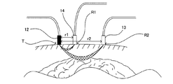
- Figure 7 is a sectional view showing a light receiving probe 13 as a reference probe 14 and the long distance r 2 which is a light transmitting probe 12 and the short range r 1, the relationship between the measurement site.
- the second received light amount information ⁇ A2 by the blood vessel existing in the skin near the light transmission point T, the blood vessel existing in the brain, and the blood vessel existing in the skin near the light receiving point R2 is obtained.
- the first light reception amount information ⁇ A1 is acquired only by the blood vessel existing in the skin near the light transmission point T (the blood vessel existing in the skin near the light receiving point R1) by the channel of the short distance r 1 .
- the received light amount information ⁇ A only from the blood vessels existing in the brain is obtained from the received light amount information ⁇ A1 and ⁇ A2 obtained in this way, using Expression (4).
- ⁇ A ⁇ A2-K ⁇ A1 (4)
- the coefficient K is calculated using the least square error.
- oxyhemoglobin concentration change / optical path length product [oxyHb], deoxyhemoglobin concentration change / optical path length product [deoxyHb] and total hemoglobin concentration change / optical path for multiple measurement sites in the brain In order to measure the long product ([oxyHb] + [deoxyHb]), for example, a near-infrared spectrometer is used (for example, see Patent Document 2).
- a near-infrared spectrometer a holder 130 is used to bring the light transmitting probe 12, the light receiving probe 13, and the reference probe 14 into contact with the surface of the subject's scalp in a predetermined arrangement.
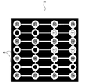
- FIG. 8 is a plan view showing an example of a holder 130 into which eight light transmitting probes 12, eight light receiving probes 13, and twelve reference probes 14 can be inserted.
- the holder 130 has twelve through-holes T1 to T8 and R1 to R8 into which eight light transmitting probes 12 T1 to 12 T8 and eight light receiving probes 13 R1 to 13 R8 can be inserted.
- the first through holes B1 to B12 into which the reference probes 14 B1 to 14 B12 can be inserted are formed.
- the second through holes T1 to T8 into which the light transmitting probes 12 T1 to 12 T8 can be inserted and the second through holes R1 to R8 into which the light receiving probes 13 R1 to 13 R8 can be inserted have four in the vertical direction and two in the horizontal direction. It is formed in a square lattice pattern so as to alternate with four.
- the first through-hole B1 reference probe 14 B1 can be inserted is between the second through-hole T1 light transmitting probe 12 T1 can be inserted and the light receiving probe 13 R3 is insertable second through hole R3, the light transmission probe 12 T1 is insertable second through hole T1 is formed at a position distant in the first set distance r 1, referred to as the second through hole T1 light transmitting probe 12 T1 can be inserted probe 14 B1
- There first setting distance r 1 is the distance between the first through-hole B1 can be inserted has a 15 mm.
- the first through-hole B2 reference probe 14 B2 can be inserted is provided with a light transmitting probe 12 T3 first through hole T3 insertable is formed at a position distant in the first set distance r 1, reference probe 14 B3 There first through-hole B3 can be inserted, as the light transmitting probe 12 T2 is formed at a position distant by a second through hole T2 can be inserted first setting distance r 1, it can be inserted each reference probe 14
- the first through holes are formed at positions separated from the second through holes into which the light transmitting probes 12 can be inserted by the first set distance r 1 .
- the above-mentioned holder 130 has twelve first through holes B1 to B12, and the reference probes 14 B1 to 14 B12 are inserted into all twelve first through holes B1 to B12 for use.
- the reference probe 14 may be inserted into only the four first through holes B for use.
- there is a problem that disturbance light is incident from the first through hole B in which the reference probe 14 is not inserted, so that the light receiving probes 13 R1 to 13 R8 detect the disturbance light.
- the present invention provides a holder capable of preventing disturbance light from entering from the first through hole and easily and accurately inserting the probe into the through hole, and an optical biometric apparatus using the holder. With the goal.
- Holder of the present invention has been made to solve the above problems, a light transmitting probe for emitting light, in a retainable holder so that the light receiving probe for receiving light are arranged in the second set distance r 2 alternately
- a plurality of first through holes are formed at positions separated from the holding position of the light transmitting probe or the holding position of the light receiving probe by the first set distance r 1 shorter than the second set distance r 2 .
- a reference probe that irradiates light or receives light can be inserted into the through hole, and the first through hole in which the reference probe is not inserted does not transmit light. Is detachable and includes the mounting member.
- the “second set distance r 2 ” is the second received light amount information based on the blood vessel existing in the skin near the light transmission point T, the blood vessel existing in the brain, and the blood vessel existing in the skin near the light receiving point R.
- the “first set distance r 1 ” is a distance for acquiring first received light amount information by blood vessels existing in the skin near the light transmission point T or the light receiving point R.
- the mounting member that does not transmit light is attached to the first through hole in which the reference probe is not inserted, disturbance light is incident from the first through hole. Can be prevented. Also, when attaching the light transmitting probe and the light receiving probe to the holder, if the mounting member is attached to the first through hole, the light transmitting probe and the light receiving probe will not be erroneously inserted into the first through hole. Furthermore, since it is only necessary to insert the light-transmitting probe and the light-receiving probe alternately into the through hole to which no mounting member is mounted, the light-transmitting probe and the light-receiving probe can be inserted easily and accurately. And when attaching a reference probe to a holder, a reference probe can also be inserted easily and correctly by removing an attachment member from a desired 1st through-hole.
- the attachment member may be detachable.
- the first through hole may be formed at the midpoint of a line connecting the holding position of the light transmitting probe and the holding position of the light receiving probe.
- the second set distance r 2 may also be is 30 mm.
- the holder as described above, the holder, the light transmitting probe that emits light, the light receiving probe that receives light, and the reference that emits light or receives light. You may make it provide a probe and the control part which controls light transmission / reception with respect to the said light transmission probe, a light reception probe, and a reference probe.
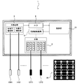
- FIG. 1 is a block diagram showing a schematic configuration of an optical biological measurement apparatus that is an embodiment of the present invention.
- the top view which shows an example when 12 attachment members are inserted in the holder in which 8 light transmission probes, 8 light reception probes, and 12 reference probes are inserted.
- the perspective view which shows an example of an attachment member.
- the top view which shows an example of the holder in which eight light transmission probes, eight light receiving probes, and eight attachment members 40 were inserted.
- a light receiving probe comprising a reference probe and long distance r 2 which is a light transmitting probe and the short range r 1, cross-sectional view showing the relationship between the measurement site.
- the top view which shows an example of the holder in which 8 light transmission probes, 8 light receiving probes, and 12 reference probes can be inserted.
- FIG. 1 is a block diagram showing a schematic configuration of an optical biological measuring apparatus according to an embodiment of the present invention.
- the optical biological measurement apparatus 1 includes a light source 2 that emits light, a light source driving mechanism 4 that drives the light source 2, a photodetector 3 that detects light, an A / D (A / D converter) 5, and a control unit. 21, eight light-transmitting probes 12, eight light-receiving probes 13, four reference probes 14, and a holder 30.
- the light source drive mechanism 4 transmits light to one light transmission probe 12 selected from among the eight light transmission probes 12 T1 to 12 T8 by a drive signal input from the control unit 21.
- Near-infrared light for example, three-wavelength light of 780 nm, 805 nm, and 830 nm
- the photodetector 3 individually detects near-infrared light (for example, three-wavelength light of 780 nm, 805 nm, and 830 nm) received by the eight light receiving probes 13 R1 to 13 R8 , so that eight second sensors are detected.
- the received light amount information ⁇ A2 ( ⁇ 1 ), ⁇ A2 ( ⁇ 2 ), ⁇ A2 ( ⁇ 3 ) is output to the control unit 21 and near-infrared light received by the four reference probes 14 (for example, 780 nm, 805 nm, and 830 nm). And the four pieces of first received light amount information ⁇ A1 ( ⁇ 1 ), ⁇ A1 ( ⁇ 2 ), ⁇ A1 ( ⁇ 3 ) are output to the control unit 21.
- the light transmission probe 12 has a cylindrical shape that can be inserted into the second through hole T. And the upper end part of the light transmission probe 12 is connected with the light source 2 via light guides, such as an optical fiber, and irradiates light from a lower end part.
- the light receiving probe 13 has a cylindrical shape similar to that of the light transmitting probe 12. The upper end of the light receiving probe 13 is connected to the light detection unit 3 via a light guide such as an optical fiber, and receives light at the lower end.
- the reference probe 14 has a cylindrical shape similar to that of the light transmission probe 12. The upper end of the light receiving probe 13 is connected to the light detection unit 3 via a light guide such as an optical fiber, and receives light at the lower end.
- FIG. 2 shows that 12 attachment members 40 are inserted in a holder 30 into which 8 light transmitting probes 12, 8 light receiving probes 13, and 12 reference probes 14 can be inserted.
- FIG. In addition, the same code
- FIG. The holder 30 has twelve second through holes T1 to T8 and R1 to R8 into which eight light transmitting probes 12 T1 to 12 T8 and eight light receiving probes 13 R1 to 13 R8 can be inserted.
- the first through holes B1 to B12 into which the reference probes 14 B1 to 14 B12 can be inserted are formed.
- the holder 30 includes twelve attachment members 40.
- FIG. 3A is a perspective view illustrating an example of the attachment member 40.
- the attachment member 40 includes a cylindrical main body portion 41, a grip portion 42 formed on the upper surface of the main body portion 41, and a cylindrical insertion portion 43 formed on the lower surface of the main body portion 41.
- the insertion portion 43 can be inserted into the first through-hole B or pulled out from the first through-hole B into which the insertion portion 43 has been inserted, that is, is detachable (FIG. 3B). reference).
- the insertion portion 43 preferably has the same shape as or slightly larger than the first through holes B1 to B12.
- the first through holes B1 to B12 have a diameter of 5 mm and a depth of 1 cm.
- the insertion portion 43 has a cylindrical shape with a diameter of 5 mm and a depth of 1 cm. Note that the depths do not have to be the same.
- the main body portion 41 preferably has a cylindrical shape having the same diameter as the annular portion serving as the periphery of the first through holes B1 to B12.
- the grasping portion 42 is grasped by a doctor, a laboratory technician, or the like, and is used for bundling a light guide path such as an optical fiber connected to the light transmission probe 12 or the like. .
- the material which comprises the said main-body part and a holding part For example, a polypropylene, a polyvinyl chloride, a polyacetal etc. are mentioned.
- a material which comprises the said insertion part For example, rubber
- the material constituting at least one of the main body part and the insertion part is required not to transmit light, but preferably the material constituting both the main body part and the insertion part is not transparent to light. It becomes.
- the attachment member 40 can be attached to the 1st through-hole B by pushing the attachment member 40 into the 1st through-hole B from upper direction, and it is attached from the 1st through-hole B.
- the attachment member 40 can be removed from the first through hole B by pulling the member 40 upward.
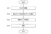
- FIG. 5 is a flowchart for explaining an example of how to use the holder 30.
- a doctor, a laboratory technician, or the like prepares the holder 30 shown in FIG.
- attachment members 40 are attached to the twelve first through holes B1 to B12, respectively.
- a doctor, a laboratory technician, or the like inserts eight light transmission probes 12 T1 to 12 T8 into the second through holes T1 to T8 and eight into the second through holes R1 to R8.
- the light receiving probes 13 R1 to 13 R8 are inserted.
- the attachment members 40 are attached to the 12 first through holes B1 to B12, the light transmitting probe 12 and the light receiving probe 13 are erroneously inserted into the first through holes B1 to B12. There is no.
- the light transmitting probe 12 and the light receiving probe 13 can be inserted easily and accurately.
- FIG. 4 is a plan view showing an example of the holder 30 when the eight light transmitting probes 12, the eight light receiving probes 13, and the eight attachment members 40 are inserted.
- a light guide such as an optical fiber connected to the light transmission probe 12 is omitted.
- step S104 a doctor, a laboratory technician, or the like starts measurement.
- the collection of the second received light amount information ⁇ A2 n ( ⁇ 1 ), ⁇ A2 n ( ⁇ 2 ), ⁇ A2 n ( ⁇ 3 ) (n 1, 2,..., 24) regarding the 24 measurement positions.
- Collection of first received light amount information ⁇ A1 m ( ⁇ 1 ), ⁇ A1 m ( ⁇ 2 ), ⁇ A1 m ( ⁇ 3 ) (m 1, 2,..., 4) regarding the four measurement positions. .
- the twelve attachment members 40 are configured to be the same, but can be identified by attaching a label with a probe number or the like to each attachment member. It is good.
- the attachment member 40 is inserted into the first through holes B1 to B12. However, the attachment member is inserted into the second through holes T1 to T8 and R1 to R8. It is good also as a structure to be.
- (3) In the optical biometric device 1 described above, a configuration is shown in which the attachment member 40 is detachably attached by pushing the attachment member 40 into the first through hole B. However, the outer peripheral surface of the insertion portion of the attachment member and the first through hole B are shown.
- the attachment member 40 has a configuration including the columnar main body portion 41, the grip portion 42, and the columnar insertion portion 43.
- a shape that does not have the grip portion 42 in the mounting member 40 a shape that does not have the grip portion 42 and the main body portion 41 in the mounting member 40, or an annular portion that is the periphery of the first through hole B It may be a cap shape (cap shape), a cotton-like body inserted into the first through hole B, or the like.
- a configuration in which one mounting member 40 is attached to one first through hole B is shown. A single attachment member may be attached.
- the present invention can be used for an optical biometric apparatus that measures brain activity non-invasively.
- Optical biometric device 12 Light transmitting probe 13: Light receiving probe 14: Reference probe 21: Control unit 30: Holder 40: Mounting member
Abstract
A holder (30) which is capable of holding light sending probes (12) that irradiate light and light receiving probes (13) that receive light so that they are alternately aligned at a second setting distance (r2), wherein a plurality of first through holes (B) are formed at positions a first setting distance (r1) away from the holding positions of the light sending probes (12) or the holding positions of the light receiving probes (13), the first setting distance (r1) being shorter than the second setting distance (r2), a reference probe (14) that irradiates light or receives light is capable of being inserted into the first through holes (B), and the first through holes (B) into which the reference probe (14) is not inserted are detachably provided with an attaching member (40) that does not transmit light.
Description
本発明は、ホルダ及びこれを用いた光生体測定装置に関する。
The present invention relates to a holder and an optical biometric apparatus using the holder.
近年、脳の活動状況を観察するために、光を用いて簡便に非侵襲で測定する光脳機能イメージング装置(光生体測定装置)が開発されている。このような光脳機能イメージング装置では、被検者の頭皮表面上に配置した送光プローブにより、異なる3種類の波長λ1、λ2、λ3(例えば、780nmと805nmと830nm)の近赤外光を脳に照射するとともに、頭皮表面上に配置した受光プローブにより、脳から放出された各波長λ1、λ2、λ3の近赤外光の強度変化(受光量情報)ΔA(λ1)、ΔA(λ2)、ΔA(λ3)をそれぞれ検出する。
そして、このようにして得られた受光量情報ΔA(λ1)、ΔA(λ2)、ΔA(λ3)から、脳血流中のオキシヘモグロビンの濃度変化・光路長積[oxyHb]と、デオキシヘモグロビンの濃度変化・光路長積[deoxyHb]とを求めるために、例えば、Modified Beer Lambert則を用いて関係式(1)(2)(3)に示す連立方程式を作成して、この連立方程式を解いている。さらには、オキシヘモグロビンの濃度変化・光路長積[oxyHb]と、デオキシヘモグロビンの濃度変化・光路長積[deoxyHb]とから総ヘモグロビンの濃度変化・光路長積([oxyHb]+[deoxyHb])を算出している。
ΔA(λ1)=EO(λ1)×[oxyHb]+Ed(λ1)×[deoxyHb]・・・(1)
ΔA(λ2)=EO(λ2)×[oxyHb]+Ed(λ2)×[deoxyHb]・・・(2)
ΔA(λ3)=EO(λ3)×[oxyHb]+Ed(λ3)×[deoxyHb]・・・(3)
なお、EO(λm)は、波長λmの光におけるオキシヘモグロビンの吸光度係数であり、Ed(λm)は、波長λmの光におけるデオキシヘモグロビンの吸光度係数である。 In recent years, in order to observe the activity state of the brain, an optical brain functional imaging apparatus (optical biometric apparatus) that performs simple noninvasive measurement using light has been developed. In such an optical brain functional imaging apparatus, a near-red light having three different wavelengths λ 1 , λ 2 , and λ 3 (for example, 780 nm, 805 nm, and 830 nm) is obtained by a light transmission probe arranged on the scalp surface of the subject. While irradiating the brain with external light, the light-receiving probe arranged on the scalp surface changes the intensity of the near-infrared light of each wavelength λ 1 , λ 2 , λ 3 (received light amount information) ΔA (λ 1 ), ΔA (λ 2 ), and ΔA (λ 3 ) are detected.
Then, from the received light amount information ΔA (λ 1 ), ΔA (λ 2 ), ΔA (λ 3 ) obtained in this way, the concentration change / optical path length product [oxyHb] of oxyhemoglobin in the cerebral blood flow, In order to obtain deoxyhemoglobin concentration change and optical path length product [deoxyHb], for example, the simultaneous equations shown in the relational expressions (1), (2) and (3) are created using the Modified Beer Lambert rule. Is solved. Furthermore, the concentration change / optical path length product ([oxyHb] + [deoxyHb]) of total hemoglobin is calculated from the concentration change / optical path length product [oxyHb] of oxyhemoglobin and the deoxyhemoglobin concentration change / optical path length product [deoxyHb]. Calculated.
ΔA (λ 1 ) = E O (λ 1 ) × [oxyHb] + E d (λ 1 ) × [deoxyHb] (1)
ΔA (λ 2 ) = E O (λ 2 ) × [oxyHb] + E d (λ 2 ) × [deoxyHb] (2)
ΔA (λ 3 ) = E O (λ 3 ) × [oxyHb] + E d (λ 3 ) × [deoxyHb] (3)
E O (λm) is an absorbance coefficient of oxyhemoglobin in light having a wavelength λm, and E d (λm) is an absorbance coefficient of deoxyhemoglobin in light having a wavelength λm.
ここで、送光プローブと受光プローブとの間の距離(チャンネル)と、測定部位との関係について説明する。図6は、一対の送光プローブ及び受光プローブと、測定部位との関係を示す図である。送光プローブ12が被検者の頭皮表面の送光点Tに押し当てられるとともに、受光プローブ13が被検者の頭皮表面の受光点Rに押し当てられる。そして、送光プローブ12から光を照射させるとともに、受光プローブ13に頭皮表面から放出される光を入射させる。このとき、頭皮表面の送光点Tから照射された光のうちで、バナナ形状(測定領域)を通過した光が頭皮表面の受光点Rに到達する。すなわち、光は、送光点T近傍の皮膚に存在する血管と、脳に存在する血管と、受光点R近傍の皮膚に存在する血管とを通過することになる。
Here, the relationship between the distance (channel) between the light transmitting probe and the light receiving probe and the measurement site will be described. FIG. 6 is a diagram illustrating a relationship between a pair of light transmitting probe and light receiving probe and a measurement site. The light transmitting probe 12 is pressed against the light transmitting point T on the surface of the subject's scalp, and the light receiving probe 13 is pressed against the light receiving point R on the surface of the subject's scalp. Then, light is emitted from the light transmitting probe 12 and light emitted from the scalp surface is incident on the light receiving probe 13. At this time, among the light irradiated from the light transmission point T on the scalp surface, the light passing through the banana shape (measurement region) reaches the light receiving point R on the scalp surface. That is, light passes through blood vessels existing in the skin near the light transmission point T, blood vessels existing in the brain, and blood vessels present in the skin near the light receiving point R.
そこで、脳に存在する血管のみによる受光量情報ΔAを取得するために、送光プローブ12と受光プローブ13との間の距離(チャンネル)を、短距離r1としたものと長距離r2としたものとを備えるものが開示されている(例えば、特許文献1や非特許文献1参照)。図7は、送光プローブ12と短距離r1となる参照プローブ14及び長距離r2となる受光プローブ13と、測定部位との関係を示す断面図である。これにより、長距離r2のチャンネルで、送光点T近傍の皮膚に存在する血管と、脳に存在する血管と、受光点R2近傍の皮膚に存在する血管とによる第二受光量情報ΔA2を取得するとともに、短距離r1のチャンネルで、送光点T近傍の皮膚に存在する血管(受光点R1近傍の皮膚に存在する血管)のみによる第一受光量情報ΔA1を取得している。
Therefore, in order to obtain the received light amount information ΔA only by the blood vessels existing in the brain, the distance (channel) between the light transmitting probe 12 and the light receiving probe 13 is the short distance r 1 and the long distance r 2 . (For example, see Patent Document 1 and Non-Patent Document 1). Figure 7 is a sectional view showing a light receiving probe 13 as a reference probe 14 and the long distance r 2 which is a light transmitting probe 12 and the short range r 1, the relationship between the measurement site. As a result, in the long-distance r 2 channel, the second received light amount information ΔA2 by the blood vessel existing in the skin near the light transmission point T, the blood vessel existing in the brain, and the blood vessel existing in the skin near the light receiving point R2 is obtained. In addition to the acquisition, the first light reception amount information ΔA1 is acquired only by the blood vessel existing in the skin near the light transmission point T (the blood vessel existing in the skin near the light receiving point R1) by the channel of the short distance r 1 .
そして、このようにして得られた受光量情報ΔA1、ΔA2から式(4)を用いて、脳に存在する血管のみによる受光量情報ΔAを求めている。
ΔA=ΔA2-KΔA1・・・(4)
ところで、式(4)において受光量情報ΔAを求めるためには係数Kを決定する必要があり、この係数Kを算出する算出方法が開示されている(例えば、非特許文献2参照)。この算出方法では、最小二乗誤差を用いて係数Kを算出している。 Then, the received light amount information ΔA only from the blood vessels existing in the brain is obtained from the received light amount information ΔA1 and ΔA2 obtained in this way, using Expression (4).
ΔA = ΔA2-KΔA1 (4)
By the way, in order to obtain the received light amount information ΔA in the equation (4), it is necessary to determine the coefficient K, and a calculation method for calculating the coefficient K is disclosed (for example, see Non-Patent Document 2). In this calculation method, the coefficient K is calculated using the least square error.
また、光脳機能イメージング装置では、脳の複数箇所の測定部位に関するオキシヘモグロビンの濃度変化・光路長積[oxyHb]、デオキシヘモグロビンの濃度変化・光路長積[deoxyHb]及び総ヘモグロビンの濃度変化・光路長積([oxyHb]+[deoxyHb])をそれぞれ測定するために、例えば、近赤外分光分析計等が利用されている(例えば、特許文献2参照)。
このような近赤外分光分析計においては、送光プローブ12や受光プローブ13や参照プローブ14を所定の配列で被検者の頭皮表面に接触させるために、ホルダ130が使用される。図8は、8個の送光プローブ12と8個の受光プローブ13と12個の参照プローブ14とが挿入されることが可能なホルダ130の一例を示す平面図である。 In the optical brain functional imaging device, oxyhemoglobin concentration change / optical path length product [oxyHb], deoxyhemoglobin concentration change / optical path length product [deoxyHb] and total hemoglobin concentration change / optical path for multiple measurement sites in the brain In order to measure the long product ([oxyHb] + [deoxyHb]), for example, a near-infrared spectrometer is used (for example, see Patent Document 2).
In such a near-infrared spectrometer, aholder 130 is used to bring the light transmitting probe 12, the light receiving probe 13, and the reference probe 14 into contact with the surface of the subject's scalp in a predetermined arrangement. FIG. 8 is a plan view showing an example of a holder 130 into which eight light transmitting probes 12, eight light receiving probes 13, and twelve reference probes 14 can be inserted.
このような近赤外分光分析計においては、送光プローブ12や受光プローブ13や参照プローブ14を所定の配列で被検者の頭皮表面に接触させるために、ホルダ130が使用される。図8は、8個の送光プローブ12と8個の受光プローブ13と12個の参照プローブ14とが挿入されることが可能なホルダ130の一例を示す平面図である。 In the optical brain functional imaging device, oxyhemoglobin concentration change / optical path length product [oxyHb], deoxyhemoglobin concentration change / optical path length product [deoxyHb] and total hemoglobin concentration change / optical path for multiple measurement sites in the brain In order to measure the long product ([oxyHb] + [deoxyHb]), for example, a near-infrared spectrometer is used (for example, see Patent Document 2).
In such a near-infrared spectrometer, a
ホルダ130は、8個の送光プローブ12T1~12T8と8個の受光プローブ13R1~13R8とを挿入することが可能となる第二貫通孔T1~T8、R1~R8と、12個の参照プローブ14B1~14B12を挿入することが可能となる第一貫通孔B1~B12とが形成されている。
送光プローブ12T1~12T8が挿入可能な第二貫通孔T1~T8と受光プローブ13R1~13R8が挿入可能な第二貫通孔R1~R8とは、縦方向に4個と横方向に4個とに交互となるように正方格子状に形成されている。このとき、送光プローブ12T1~12T8が挿入可能な第二貫通孔T1~T8と受光プローブ13R1~13R8が挿入可能な第二貫通孔R1~R8との間の間隔(チャンネル)である第二設定距離r2は、30mmとなっている。これにより、24箇所の計測位置に関する第二受光量情報ΔA2n(λ1)、ΔA2n(λ2)、ΔA2n(λ3)(n=1,2,・・・,24)の収集を行うことができるようになっている。 Theholder 130 has twelve through-holes T1 to T8 and R1 to R8 into which eight light transmitting probes 12 T1 to 12 T8 and eight light receiving probes 13 R1 to 13 R8 can be inserted. The first through holes B1 to B12 into which the reference probes 14 B1 to 14 B12 can be inserted are formed.
The second through holes T1 to T8 into which the light transmittingprobes 12 T1 to 12 T8 can be inserted and the second through holes R1 to R8 into which the light receiving probes 13 R1 to 13 R8 can be inserted have four in the vertical direction and two in the horizontal direction. It is formed in a square lattice pattern so as to alternate with four. At this time, at intervals (channels) between the second through holes T1 to T8 into which the light transmitting probes 12 T1 to 12 T8 can be inserted and the second through holes R1 to R8 into which the light receiving probes 13 R1 to 13 R8 can be inserted. there second set distance r 2 has a 30 mm. Thereby, the collection of the second received light amount information ΔA2 n (λ 1 ), ΔA2 n (λ 2 ), ΔA2 n (λ 3 ) (n = 1, 2,..., 24) regarding the 24 measurement positions. Can be done.
送光プローブ12T1~12T8が挿入可能な第二貫通孔T1~T8と受光プローブ13R1~13R8が挿入可能な第二貫通孔R1~R8とは、縦方向に4個と横方向に4個とに交互となるように正方格子状に形成されている。このとき、送光プローブ12T1~12T8が挿入可能な第二貫通孔T1~T8と受光プローブ13R1~13R8が挿入可能な第二貫通孔R1~R8との間の間隔(チャンネル)である第二設定距離r2は、30mmとなっている。これにより、24箇所の計測位置に関する第二受光量情報ΔA2n(λ1)、ΔA2n(λ2)、ΔA2n(λ3)(n=1,2,・・・,24)の収集を行うことができるようになっている。 The
The second through holes T1 to T8 into which the light transmitting
また、参照プローブ14B1が挿入可能な第一貫通孔B1は、送光プローブ12T1が挿入可能な第二貫通孔T1と受光プローブ13R3が挿入可能な第二貫通孔R3との間で、送光プローブ12T1が挿入可能な第二貫通孔T1と第一設定距離r1で離れた位置に形成されており、送光プローブ12T1が挿入可能な第二貫通孔T1と参照プローブ14B1が挿入可能な第一貫通孔B1との間の間隔である第一設定距離r1は、15mmとなっている。そして、参照プローブ14B2が挿入可能な第一貫通孔B2は、送光プローブ12T3が挿入可能な第一貫通孔T3と第一設定距離r1で離れた位置に形成され、参照プローブ14B3が挿入可能な第一貫通孔B3は、送光プローブ12T2が挿入可能な第二貫通孔T2と第一設定距離r1で離れた位置に形成されるように、各参照プローブ14が挿入可能な第一貫通孔は、各送光プローブ12が挿入可能な第二貫通孔と第一設定距離r1で離れた位置にそれぞれ形成されている。これにより、12箇所の計測位置に関する第一受光量情報ΔA1m(λ1)、ΔA1m(λ2)、ΔA1m(λ3)(m=1,2,・・・,12)の収集を行うことができるようになっている。
The first through-hole B1 reference probe 14 B1 can be inserted is between the second through-hole T1 light transmitting probe 12 T1 can be inserted and the light receiving probe 13 R3 is insertable second through hole R3, the light transmission probe 12 T1 is insertable second through hole T1 is formed at a position distant in the first set distance r 1, referred to as the second through hole T1 light transmitting probe 12 T1 can be inserted probe 14 B1 There first setting distance r 1 is the distance between the first through-hole B1 can be inserted has a 15 mm. Then, the first through-hole B2 reference probe 14 B2 can be inserted is provided with a light transmitting probe 12 T3 first through hole T3 insertable is formed at a position distant in the first set distance r 1, reference probe 14 B3 There first through-hole B3 can be inserted, as the light transmitting probe 12 T2 is formed at a position distant by a second through hole T2 can be inserted first setting distance r 1, it can be inserted each reference probe 14 The first through holes are formed at positions separated from the second through holes into which the light transmitting probes 12 can be inserted by the first set distance r 1 . Thereby, the collection of the first received light amount information ΔA1 m (λ 1 ), ΔA1 m (λ 2 ), ΔA1 m (λ 3 ) (m = 1, 2,..., 12) regarding the 12 measurement positions. Can be done.
ところで、上述したホルダ130には、12個の第一貫通孔B1~B12が形成されているが、12個全部の第一貫通孔B1~B12に参照プローブ14B1~14B12を挿入して使用することもあるが、例えば、4個の第一貫通孔Bのみに参照プローブ14を挿入して使用することもある。このとき、参照プローブ14が挿入されていない第一貫通孔Bから外乱光が入射することにより、受光プローブ13R1~13R8が外乱光を検出してしまうという問題点があった。
By the way, the above-mentioned holder 130 has twelve first through holes B1 to B12, and the reference probes 14 B1 to 14 B12 are inserted into all twelve first through holes B1 to B12 for use. For example, the reference probe 14 may be inserted into only the four first through holes B for use. At this time, there is a problem that disturbance light is incident from the first through hole B in which the reference probe 14 is not inserted, so that the light receiving probes 13 R1 to 13 R8 detect the disturbance light.
また、上述したホルダ130に、8個の送光プローブ12と8個の受光プローブ13と4個の参照プローブ14とを挿入して使用することになるが、多くの貫通孔T1~T8、R1~R8、B1~B12が存在するため、どの貫通孔にどのプローブを挿入すればよいかを把握することが難しく、挿入に時間がかかったり、間違えたりすることがあった。
そこで、本発明は、第一貫通孔から外乱光が入射することを防止するとともに、貫通孔にプローブを容易かつ正確に挿入することができるホルダ及びこれを用いた光生体測定装置を提供することを目的とする。 In addition, eight light-transmittingprobes 12, eight light-receiving probes 13, and four reference probes 14 are inserted into the holder 130 described above, and many through holes T1 to T8, R1 are used. Since R8 and B1 to B12 exist, it is difficult to know which probe should be inserted into which through-hole, and insertion may take time or may be wrong.
Accordingly, the present invention provides a holder capable of preventing disturbance light from entering from the first through hole and easily and accurately inserting the probe into the through hole, and an optical biometric apparatus using the holder. With the goal.
そこで、本発明は、第一貫通孔から外乱光が入射することを防止するとともに、貫通孔にプローブを容易かつ正確に挿入することができるホルダ及びこれを用いた光生体測定装置を提供することを目的とする。 In addition, eight light-transmitting
Accordingly, the present invention provides a holder capable of preventing disturbance light from entering from the first through hole and easily and accurately inserting the probe into the through hole, and an optical biometric apparatus using the holder. With the goal.
上記課題を解決するためになされた本発明のホルダは、光を照射する送光プローブと、光を受光する受光プローブとが交互に第二設定距離r2で並べられるように保持可能なホルダであって、送光プローブの保持位置又は受光プローブの保持位置から第二設定距離r2より短い第一設定距離r1で離れた位置に複数の第一貫通孔が形成されており、前記第一貫通孔には、光を照射するか若しくは光を受光する参照プローブが挿入されることが可能となっており、前記参照プローブが挿入されていない第一貫通孔には、光を透過しない取付部材が着脱可能となっており、前記取付部材を備えるようにしている。
Holder of the present invention has been made to solve the above problems, a light transmitting probe for emitting light, in a retainable holder so that the light receiving probe for receiving light are arranged in the second set distance r 2 alternately A plurality of first through holes are formed at positions separated from the holding position of the light transmitting probe or the holding position of the light receiving probe by the first set distance r 1 shorter than the second set distance r 2 . A reference probe that irradiates light or receives light can be inserted into the through hole, and the first through hole in which the reference probe is not inserted does not transmit light. Is detachable and includes the mounting member.
ここで、「第二設定距離r2」は、送光点T近傍の皮膚に存在する血管と、脳に存在する血管と、受光点R近傍の皮膚に存在する血管とによる第二受光量情報を取得するための距離であり、「第一設定距離r1」は、送光点T又は受光点R近傍の皮膚に存在する血管による第一受光量情報を取得するための距離である。
Here, the “second set distance r 2 ” is the second received light amount information based on the blood vessel existing in the skin near the light transmission point T, the blood vessel existing in the brain, and the blood vessel existing in the skin near the light receiving point R. The “first set distance r 1 ” is a distance for acquiring first received light amount information by blood vessels existing in the skin near the light transmission point T or the light receiving point R.
以上のように、本発明のホルダによれば、参照プローブが挿入されていない第一貫通孔には、光を透過しない取付部材が取り付けられるので、第一貫通孔から外乱光が入射することを防止することができる。
また、送光プローブと受光プローブとをホルダに取り付ける際には、第一貫通孔に取付部材を取り付けておくと、送光プローブと受光プローブとを第一貫通孔に誤って挿入することはなく、さらに取付部材が取り付けられていない貫通孔に、送光プローブと受光プローブとが交互となるように挿入すればよいので、送光プローブと受光プローブとを容易かつ正確に挿入することができる。そして、参照プローブをホルダに取り付ける際には、所望の第一貫通孔から取付部材を取り外すことで、参照プローブも容易かつ正確に挿入することができる。 As described above, according to the holder of the present invention, since the mounting member that does not transmit light is attached to the first through hole in which the reference probe is not inserted, disturbance light is incident from the first through hole. Can be prevented.
Also, when attaching the light transmitting probe and the light receiving probe to the holder, if the mounting member is attached to the first through hole, the light transmitting probe and the light receiving probe will not be erroneously inserted into the first through hole. Furthermore, since it is only necessary to insert the light-transmitting probe and the light-receiving probe alternately into the through hole to which no mounting member is mounted, the light-transmitting probe and the light-receiving probe can be inserted easily and accurately. And when attaching a reference probe to a holder, a reference probe can also be inserted easily and correctly by removing an attachment member from a desired 1st through-hole.
(その他の課題を解決するための手段及び効果)
また、本発明のホルダにおいては、送光プローブ又は受光プローブが挿入されることが可能な複数の第二貫通孔が形成されており、送光プローブ又は受光プローブが挿入されていない第二貫通孔には、前記取付部材が着脱可能となっているようにしてもよい。 (Means and effects for solving other problems)
In the holder of the present invention, a plurality of second through holes into which the light transmitting probe or the light receiving probe can be inserted are formed, and the second through hole into which the light transmitting probe or the light receiving probe is not inserted Alternatively, the attachment member may be detachable.
また、本発明のホルダにおいては、前記第一貫通孔は、送光プローブの保持位置と受光プローブの保持位置とを結んだ線の中点に形成されているようにしてもよい。
本発明のホルダによれば、取付部材がなければ脳の計測位置に外乱光が入射することになるが、取付部材が存在するので、外乱光が入射することを防止することができる。 In the holder of the present invention, the first through hole may be formed at the midpoint of a line connecting the holding position of the light transmitting probe and the holding position of the light receiving probe.
According to the holder of the present invention, if there is no attachment member, disturbance light is incident on the measurement position of the brain. However, since the attachment member is present, it is possible to prevent disturbance light from entering.
そして、本発明のホルダにおいては、前記第二設定距離r2は、30mmであるようにしてもよい。
さらに、本発明の光生体測定装置においては、上述したようなホルダと、ホルダと、光を照射する送光プローブと、光を受光する受光プローブと、光を照射するか若しくは光を受光する参照プローブと、前記送光プローブ、受光プローブ及び参照プローブに対して光の送受光を制御する制御部とを備えるようにしてもよい。 Then, in the holder of the present invention, the second set distance r 2 may also be is 30 mm.
Further, in the photobiological measurement device of the present invention, the holder as described above, the holder, the light transmitting probe that emits light, the light receiving probe that receives light, and the reference that emits light or receives light. You may make it provide a probe and the control part which controls light transmission / reception with respect to the said light transmission probe, a light reception probe, and a reference probe.
以下、本発明の実施形態について図面を用いて説明する。なお、本発明は、以下に説明するような実施形態に限定されるものではなく、本発明の趣旨を逸脱しない範囲で種々の態様が含まれる。
Hereinafter, embodiments of the present invention will be described with reference to the drawings. Note that the present invention is not limited to the embodiments described below, and includes various modes without departing from the spirit of the present invention.
図1は、本発明の一実施形態である光生体計測装置の概略構成を示すブロック図である。光生体計測装置1は、光を出射する光源2と、光源2を駆動する光源駆動機構4と、光を検出する光検出器3と、A/D(A/Dコンバータ)5と、制御部21とを備えるとともに、8個の送光プローブ12と、8個の受光プローブ13と、4個の参照プローブ14と、ホルダ30とを備える。
FIG. 1 is a block diagram showing a schematic configuration of an optical biological measuring apparatus according to an embodiment of the present invention. The optical biological measurement apparatus 1 includes a light source 2 that emits light, a light source driving mechanism 4 that drives the light source 2, a photodetector 3 that detects light, an A / D (A / D converter) 5, and a control unit. 21, eight light-transmitting probes 12, eight light-receiving probes 13, four reference probes 14, and a holder 30.
光源駆動機構4は、制御部21から入力された駆動信号により8個の送光プローブ12T1~12T8のうちから選択される1個の送光プローブ12に光を送光する。上記光としては、近赤外光(例えば、780nmと805nmと830nmとの3波長光)が用いられる。
光検出器3は、8個の受光プローブ13R1~13R8で受光した近赤外光(例えば、780nmと805nmと830nmとの3波長光)を個別に検出することにより、8個の第二受光量情報ΔA2(λ1)、ΔA2(λ2)、ΔA2(λ3)を制御部21に出力するとともに、4個の参照プローブ14で受光した近赤外光(例えば、780nmと805nmと830nmとの3波長光)を個別に検出することにより、4個の第一受光量情報ΔA1(λ1)、ΔA1(λ2)、ΔA1(λ3)を制御部21に出力する。 The light source drive mechanism 4 transmits light to onelight transmission probe 12 selected from among the eight light transmission probes 12 T1 to 12 T8 by a drive signal input from the control unit 21. Near-infrared light (for example, three-wavelength light of 780 nm, 805 nm, and 830 nm) is used as the light.
Thephotodetector 3 individually detects near-infrared light (for example, three-wavelength light of 780 nm, 805 nm, and 830 nm) received by the eight light receiving probes 13 R1 to 13 R8 , so that eight second sensors are detected. The received light amount information ΔA2 (λ 1 ), ΔA2 (λ 2 ), ΔA2 (λ 3 ) is output to the control unit 21 and near-infrared light received by the four reference probes 14 (for example, 780 nm, 805 nm, and 830 nm). And the four pieces of first received light amount information ΔA1 (λ 1 ), ΔA1 (λ 2 ), ΔA1 (λ 3 ) are output to the control unit 21.
光検出器3は、8個の受光プローブ13R1~13R8で受光した近赤外光(例えば、780nmと805nmと830nmとの3波長光)を個別に検出することにより、8個の第二受光量情報ΔA2(λ1)、ΔA2(λ2)、ΔA2(λ3)を制御部21に出力するとともに、4個の参照プローブ14で受光した近赤外光(例えば、780nmと805nmと830nmとの3波長光)を個別に検出することにより、4個の第一受光量情報ΔA1(λ1)、ΔA1(λ2)、ΔA1(λ3)を制御部21に出力する。 The light source drive mechanism 4 transmits light to one
The
送光プローブ12は、第二貫通孔Tに挿入可能な円柱形状をしている。そして、送光プローブ12の上端部は、光ファイバ等の導光路を介して光源2と接続され、下端部から光を照射するようになっている。
受光プローブ13も、送光プローブ12と同様の円柱形状をしている。そして、受光プローブ13の上端部は、光ファイバ等の導光路を介して光検出部3と接続され、その下端部で光を受光するようになっている。
参照プローブ14も、送光プローブ12と同様の円柱形状をしている。そして、受光プローブ13の上端部は、光ファイバ等の導光路を介して光検出部3と接続され、その下端部で光を受光するようになっている。 Thelight transmission probe 12 has a cylindrical shape that can be inserted into the second through hole T. And the upper end part of the light transmission probe 12 is connected with the light source 2 via light guides, such as an optical fiber, and irradiates light from a lower end part.
Thelight receiving probe 13 has a cylindrical shape similar to that of the light transmitting probe 12. The upper end of the light receiving probe 13 is connected to the light detection unit 3 via a light guide such as an optical fiber, and receives light at the lower end.
Thereference probe 14 has a cylindrical shape similar to that of the light transmission probe 12. The upper end of the light receiving probe 13 is connected to the light detection unit 3 via a light guide such as an optical fiber, and receives light at the lower end.
受光プローブ13も、送光プローブ12と同様の円柱形状をしている。そして、受光プローブ13の上端部は、光ファイバ等の導光路を介して光検出部3と接続され、その下端部で光を受光するようになっている。
参照プローブ14も、送光プローブ12と同様の円柱形状をしている。そして、受光プローブ13の上端部は、光ファイバ等の導光路を介して光検出部3と接続され、その下端部で光を受光するようになっている。 The
The
The
ここで、図2は、8個の送光プローブ12と8個の受光プローブ13と12個の参照プローブ14とが挿入されることが可能なホルダ30において、12個の取付部材40が挿入されたときの一例を示す平面図である。なお、ホルダ130と同様のものについては、同じ符号を付している。
ホルダ30は、8個の送光プローブ12T1~12T8と8個の受光プローブ13R1~13R8とを挿入することが可能となる第二貫通孔T1~T8、R1~R8と、12個の参照プローブ14B1~14B12を挿入することが可能となる第一貫通孔B1~B12とが形成されている。 Here, FIG. 2 shows that 12attachment members 40 are inserted in a holder 30 into which 8 light transmitting probes 12, 8 light receiving probes 13, and 12 reference probes 14 can be inserted. FIG. In addition, the same code | symbol is attached | subjected about the thing similar to the holder 130. FIG.
Theholder 30 has twelve second through holes T1 to T8 and R1 to R8 into which eight light transmitting probes 12 T1 to 12 T8 and eight light receiving probes 13 R1 to 13 R8 can be inserted. The first through holes B1 to B12 into which the reference probes 14 B1 to 14 B12 can be inserted are formed.
ホルダ30は、8個の送光プローブ12T1~12T8と8個の受光プローブ13R1~13R8とを挿入することが可能となる第二貫通孔T1~T8、R1~R8と、12個の参照プローブ14B1~14B12を挿入することが可能となる第一貫通孔B1~B12とが形成されている。 Here, FIG. 2 shows that 12
The
本発明に係るホルダ30は、12個の取付部材40を備える。図3(a)は、取付部材40の一例を示す斜視図である。取付部材40は、円柱形状の本体部41と、本体部41の上面に形成された把持部42と、本体部41の下面に形成された円柱形状の挿入部43とを有する。
挿入部43は、第一貫通孔Bに挿入されたり、挿入部43が挿入された第一貫通孔Bから引き抜かれたり可能となっており、すなわち着脱可能となっている(図3(b)参照)。具体的には、挿入部43は、第一貫通孔B1~B12と同じ形状をしているか、若干大きくすることが好ましく、例えば、第一貫通孔B1~B12が直径5mm、深さ1cmの円柱形状をしている場合には、挿入部43は直径5mm、深さ1cmの円柱形状をしている。なお、深さは同じでなくてもよい。
本体部41は、第一貫通孔B1~B12の周縁となる円環部と同じ直径を持つ円柱形状であることが好ましい。
また、把持部42は、医師や検査技師等に把持されるようになっているとともに、送光プローブ12等に接続された光ファイバ等の導光路を束ねるために使用されるようになっている。 Theholder 30 according to the present invention includes twelve attachment members 40. FIG. 3A is a perspective view illustrating an example of the attachment member 40. The attachment member 40 includes a cylindrical main body portion 41, a grip portion 42 formed on the upper surface of the main body portion 41, and a cylindrical insertion portion 43 formed on the lower surface of the main body portion 41.
Theinsertion portion 43 can be inserted into the first through-hole B or pulled out from the first through-hole B into which the insertion portion 43 has been inserted, that is, is detachable (FIG. 3B). reference). Specifically, the insertion portion 43 preferably has the same shape as or slightly larger than the first through holes B1 to B12. For example, the first through holes B1 to B12 have a diameter of 5 mm and a depth of 1 cm. In the case of a shape, the insertion portion 43 has a cylindrical shape with a diameter of 5 mm and a depth of 1 cm. Note that the depths do not have to be the same.
Themain body portion 41 preferably has a cylindrical shape having the same diameter as the annular portion serving as the periphery of the first through holes B1 to B12.
In addition, the graspingportion 42 is grasped by a doctor, a laboratory technician, or the like, and is used for bundling a light guide path such as an optical fiber connected to the light transmission probe 12 or the like. .
挿入部43は、第一貫通孔Bに挿入されたり、挿入部43が挿入された第一貫通孔Bから引き抜かれたり可能となっており、すなわち着脱可能となっている(図3(b)参照)。具体的には、挿入部43は、第一貫通孔B1~B12と同じ形状をしているか、若干大きくすることが好ましく、例えば、第一貫通孔B1~B12が直径5mm、深さ1cmの円柱形状をしている場合には、挿入部43は直径5mm、深さ1cmの円柱形状をしている。なお、深さは同じでなくてもよい。
本体部41は、第一貫通孔B1~B12の周縁となる円環部と同じ直径を持つ円柱形状であることが好ましい。
また、把持部42は、医師や検査技師等に把持されるようになっているとともに、送光プローブ12等に接続された光ファイバ等の導光路を束ねるために使用されるようになっている。 The
The
The
In addition, the grasping
なお、上記本体部及び把持部を構成する材質としては、特に限定されるものではないが、例えば、ポリプロピレン、ポリ塩化ビニル、ポリアセタール等が挙げられる。また、上記挿入部を構成する材質としては、特に限定されるものではないが、例えば、ゴム等が挙げられる。
そして、本体部と挿入部との少なくとも一方を構成する材質は、光を透過しないものとする必要があるが、好ましくは本体部と挿入部との両方を構成する材質は、光を透過しないものとなる。
このような取付部材40であれば、第一貫通孔Bに取付部材40を上方から押し込むことにより、第一貫通孔Bに取付部材40を取り付けることができ、また、第一貫通孔Bから取付部材40を上方に引き抜くことにより、第一貫通孔Bから取付部材40を取り外すことができる。 In addition, although it does not specifically limit as a material which comprises the said main-body part and a holding part, For example, a polypropylene, a polyvinyl chloride, a polyacetal etc. are mentioned. Moreover, although it does not specifically limit as a material which comprises the said insertion part, For example, rubber | gum etc. are mentioned.
The material constituting at least one of the main body part and the insertion part is required not to transmit light, but preferably the material constituting both the main body part and the insertion part is not transparent to light. It becomes.
If it is such anattachment member 40, the attachment member 40 can be attached to the 1st through-hole B by pushing the attachment member 40 into the 1st through-hole B from upper direction, and it is attached from the 1st through-hole B. The attachment member 40 can be removed from the first through hole B by pulling the member 40 upward.
そして、本体部と挿入部との少なくとも一方を構成する材質は、光を透過しないものとする必要があるが、好ましくは本体部と挿入部との両方を構成する材質は、光を透過しないものとなる。
このような取付部材40であれば、第一貫通孔Bに取付部材40を上方から押し込むことにより、第一貫通孔Bに取付部材40を取り付けることができ、また、第一貫通孔Bから取付部材40を上方に引き抜くことにより、第一貫通孔Bから取付部材40を取り外すことができる。 In addition, although it does not specifically limit as a material which comprises the said main-body part and a holding part, For example, a polypropylene, a polyvinyl chloride, a polyacetal etc. are mentioned. Moreover, although it does not specifically limit as a material which comprises the said insertion part, For example, rubber | gum etc. are mentioned.
The material constituting at least one of the main body part and the insertion part is required not to transmit light, but preferably the material constituting both the main body part and the insertion part is not transparent to light. It becomes.
If it is such an
次に、本発明に係るホルダ30の使用方法について説明する。図5は、ホルダ30の使用方法の一例について説明するためのフローチャートである。
まず、ステップS101の処理において、医師や検査技師等は、図2に示すホルダ30を準備する。このとき、12個の第一貫通孔B1~B12には、それぞれ取付部材40が取り付けられている。 Next, the usage method of theholder 30 which concerns on this invention is demonstrated. FIG. 5 is a flowchart for explaining an example of how to use the holder 30.
First, in the process of step S101, a doctor, a laboratory technician, or the like prepares theholder 30 shown in FIG. At this time, attachment members 40 are attached to the twelve first through holes B1 to B12, respectively.
まず、ステップS101の処理において、医師や検査技師等は、図2に示すホルダ30を準備する。このとき、12個の第一貫通孔B1~B12には、それぞれ取付部材40が取り付けられている。 Next, the usage method of the
First, in the process of step S101, a doctor, a laboratory technician, or the like prepares the
次に、ステップS102の処理において、医師や検査技師等は、第二貫通孔T1~T8に8個の送光プローブ12T1~12T8を挿入するとともに、第二貫通孔R1~R8に8個の受光プローブ13R1~13R8を挿入する。このとき、12個の第一貫通孔B1~B12には、それぞれ取付部材40が取り付けられているので、送光プローブ12と受光プローブ13とを第一貫通孔B1~B12に誤って挿入することはない。さらに送光プローブ12と受光プローブ13とが交互となるように挿入すればよいので、送光プローブ12と受光プローブ13とを容易かつ正確に挿入することができる。
Next, in the process of step S102, a doctor, a laboratory technician, or the like inserts eight light transmission probes 12 T1 to 12 T8 into the second through holes T1 to T8 and eight into the second through holes R1 to R8. The light receiving probes 13 R1 to 13 R8 are inserted. At this time, since the attachment members 40 are attached to the 12 first through holes B1 to B12, the light transmitting probe 12 and the light receiving probe 13 are erroneously inserted into the first through holes B1 to B12. There is no. Furthermore, since it is only necessary to insert the light transmitting probe 12 and the light receiving probe 13 alternately, the light transmitting probe 12 and the light receiving probe 13 can be inserted easily and accurately.
次に、ステップS103の処理において、医師や検査技師等は、所望の4個の第一貫通孔B3、B4、B7、B8から取付部材40を取り外して、所望の4個の第一貫通孔B3、B4、B7、B8に4個の参照プローブ14を挿入する。図4は、8個の送光プローブ12と8個の受光プローブ13と8個の取付部材40とが挿入されたときのホルダ30の一例を示す平面図である。なお、送光プローブ12等に接続された光ファイバ等の導光路は省略している。
Next, in the process of step S103, a doctor, a laboratory technician, or the like removes the attachment member 40 from the desired four first through holes B3, B4, B7, B8, and the desired four first through holes B3. , B4, B7, B8, four reference probes 14 are inserted. FIG. 4 is a plan view showing an example of the holder 30 when the eight light transmitting probes 12, the eight light receiving probes 13, and the eight attachment members 40 are inserted. A light guide such as an optical fiber connected to the light transmission probe 12 is omitted.
次に、ステップS104の処理において、医師や検査技師等は、測定を開始する。これにより、24箇所の計測位置に関する第二受光量情報ΔA2n(λ1)、ΔA2n(λ2)、ΔA2n(λ3)(n=1,2,・・・,24)の収集と、4箇所の計測位置に関する第一受光量情報ΔA1m(λ1)、ΔA1m(λ2)、ΔA1m(λ3)(m=1,2,・・・,4)の収集とを行う。
このとき、参照プローブ14が挿入されていない第一貫通孔B1、B2、B5、B6、B9~B12には、取付部材40が取り付けられているので、第一貫通孔B1、B2、B5、B6、B9~B12から外乱光が入射することを防止することができる。
そして、ステップS104の処理が終了したときには、本フローチャートを終了させる。 Next, in the process of step S104, a doctor, a laboratory technician, or the like starts measurement. As a result, the collection of the second received light amount information ΔA2 n (λ 1 ), ΔA2 n (λ 2 ), ΔA2 n (λ 3 ) (n = 1, 2,..., 24) regarding the 24 measurement positions. Collection of first received light amount information ΔA1 m (λ 1 ), ΔA1 m (λ 2 ), ΔA1 m (λ 3 ) (m = 1, 2,..., 4) regarding the four measurement positions. .
At this time, since theattachment member 40 is attached to the first through holes B1, B2, B5, B6, B9 to B12 in which the reference probe 14 is not inserted, the first through holes B1, B2, B5, B6 are attached. , B9 to B12 can prevent disturbance light from entering.
Then, when the process of step S104 ends, this flowchart is ended.
このとき、参照プローブ14が挿入されていない第一貫通孔B1、B2、B5、B6、B9~B12には、取付部材40が取り付けられているので、第一貫通孔B1、B2、B5、B6、B9~B12から外乱光が入射することを防止することができる。
そして、ステップS104の処理が終了したときには、本フローチャートを終了させる。 Next, in the process of step S104, a doctor, a laboratory technician, or the like starts measurement. As a result, the collection of the second received light amount information ΔA2 n (λ 1 ), ΔA2 n (λ 2 ), ΔA2 n (λ 3 ) (n = 1, 2,..., 24) regarding the 24 measurement positions. Collection of first received light amount information ΔA1 m (λ 1 ), ΔA1 m (λ 2 ), ΔA1 m (λ 3 ) (m = 1, 2,..., 4) regarding the four measurement positions. .
At this time, since the
Then, when the process of step S104 ends, this flowchart is ended.
<他の実施形態>
(1)上述した光生体計測装置1では、12個の取付部材40は同一のものである構成を示したが、各取付部材にプローブ番号等が付されたラベルを取り付けることにより、識別できる構成としてもよい。
(2)上述した光生体計測装置1では、取付部材40は第一貫通孔B1~B12に挿入される構成を示したが、取付部材は第二貫通孔T1~T8、R1~R8に挿入される構成としてもよい。
(3)上述した光生体計測装置1では、第一貫通孔Bに取付部材40を押し込む押し込み方式で着脱可能となる構成を示したが、取付部材の挿入部の外周面と第一貫通孔Bの内周面とに、ネジが設けられており、ネジ式で着脱可能となる構成としてもよい。
(4)上述した光生体計測装置1では、第一貫通孔Bに取付部材40を押し込む押し込み方式で着脱可能となる構成を示したが、第一貫通孔Bの周縁となる円環部の上面に、円盤形状の下面を粘着剤で貼り付ける貼付式で着脱可能となる構成としてもよい。
(5)上述した光生体計測装置1では、取付部材40は、円柱形状の本体部41と、把持部42と、円柱形状の挿入部43とを有する構成を示したが、取付部材は、第一貫通孔Bから光が入射しないものであればよい。例えば、取付部材40において把持部42を有さない形状や、取付部材40において把持部42と本体部41とを有さない形状や、第一貫通孔Bの周縁となる円環部を包むようなキャップ状(帽子状)や、第一貫通孔Bに挿入する綿状体等であってもよい。
(6)上述した光生体計測装置1では、1個の第一貫通孔Bには1個の取付部材40を取る付ける構成を示したが、2個等の複数個の第一貫通孔Bに1個の取付部材を取り付けるようなものであってもよい。 <Other embodiments>
(1) In the opticalbiological measuring apparatus 1 described above, the twelve attachment members 40 are configured to be the same, but can be identified by attaching a label with a probe number or the like to each attachment member. It is good.
(2) In the opticalbiological measuring apparatus 1 described above, the attachment member 40 is inserted into the first through holes B1 to B12. However, the attachment member is inserted into the second through holes T1 to T8 and R1 to R8. It is good also as a structure to be.
(3) In the opticalbiometric device 1 described above, a configuration is shown in which the attachment member 40 is detachably attached by pushing the attachment member 40 into the first through hole B. However, the outer peripheral surface of the insertion portion of the attachment member and the first through hole B are shown. It is good also as a structure which is provided with the screw | thread in the inner peripheral surface of this, and can attach or detach with a screw type.
(4) In the opticalbiological measurement apparatus 1 described above, the configuration that can be attached and detached by the pushing method of pushing the attachment member 40 into the first through-hole B has been shown, but the upper surface of the annular portion serving as the periphery of the first through-hole B Moreover, it is good also as a structure which can be attached or detached by the sticking type which sticks a disk-shaped lower surface with an adhesive.
(5) In the opticalbiological measuring apparatus 1 described above, the attachment member 40 has a configuration including the columnar main body portion 41, the grip portion 42, and the columnar insertion portion 43. What is necessary is that light does not enter from one through hole B. For example, a shape that does not have the grip portion 42 in the mounting member 40, a shape that does not have the grip portion 42 and the main body portion 41 in the mounting member 40, or an annular portion that is the periphery of the first through hole B It may be a cap shape (cap shape), a cotton-like body inserted into the first through hole B, or the like.
(6) In the opticalbiological measuring apparatus 1 described above, a configuration in which one mounting member 40 is attached to one first through hole B is shown. A single attachment member may be attached.
(1)上述した光生体計測装置1では、12個の取付部材40は同一のものである構成を示したが、各取付部材にプローブ番号等が付されたラベルを取り付けることにより、識別できる構成としてもよい。
(2)上述した光生体計測装置1では、取付部材40は第一貫通孔B1~B12に挿入される構成を示したが、取付部材は第二貫通孔T1~T8、R1~R8に挿入される構成としてもよい。
(3)上述した光生体計測装置1では、第一貫通孔Bに取付部材40を押し込む押し込み方式で着脱可能となる構成を示したが、取付部材の挿入部の外周面と第一貫通孔Bの内周面とに、ネジが設けられており、ネジ式で着脱可能となる構成としてもよい。
(4)上述した光生体計測装置1では、第一貫通孔Bに取付部材40を押し込む押し込み方式で着脱可能となる構成を示したが、第一貫通孔Bの周縁となる円環部の上面に、円盤形状の下面を粘着剤で貼り付ける貼付式で着脱可能となる構成としてもよい。
(5)上述した光生体計測装置1では、取付部材40は、円柱形状の本体部41と、把持部42と、円柱形状の挿入部43とを有する構成を示したが、取付部材は、第一貫通孔Bから光が入射しないものであればよい。例えば、取付部材40において把持部42を有さない形状や、取付部材40において把持部42と本体部41とを有さない形状や、第一貫通孔Bの周縁となる円環部を包むようなキャップ状(帽子状)や、第一貫通孔Bに挿入する綿状体等であってもよい。
(6)上述した光生体計測装置1では、1個の第一貫通孔Bには1個の取付部材40を取る付ける構成を示したが、2個等の複数個の第一貫通孔Bに1個の取付部材を取り付けるようなものであってもよい。 <Other embodiments>
(1) In the optical
(2) In the optical
(3) In the optical
(4) In the optical
(5) In the optical
(6) In the optical
本発明は、非侵襲で脳活動を測定する光生体測定装置等に利用することができる。
The present invention can be used for an optical biometric apparatus that measures brain activity non-invasively.
1: 光生体測定装置
12: 送光プローブ
13: 受光プローブ
14: 参照プローブ
21: 制御部
30: ホルダ
40: 取付部材 1: Optical biometric device 12: Light transmitting probe 13: Light receiving probe 14: Reference probe 21: Control unit 30: Holder 40: Mounting member
12: 送光プローブ
13: 受光プローブ
14: 参照プローブ
21: 制御部
30: ホルダ
40: 取付部材 1: Optical biometric device 12: Light transmitting probe 13: Light receiving probe 14: Reference probe 21: Control unit 30: Holder 40: Mounting member
Claims (5)
- 光を照射する送光プローブと、光を受光する受光プローブとが交互に第二設定距離r2で並べられるように保持可能なホルダであって、
送光プローブの保持位置又は受光プローブの保持位置から第二設定距離r2より短い第一設定距離r1で離れた位置に複数の第一貫通孔が形成されており、
前記第一貫通孔には、光を照射するか若しくは光を受光する参照プローブが挿入されることが可能となっており、
前記参照プローブが挿入されていない第一貫通孔には、光を透過しない取付部材が着脱可能となっており、
前記取付部材を備えることを特徴とするホルダ。 A holder capable of holding a light transmitting probe for irradiating light and a light receiving probe for receiving light alternately arranged at a second set distance r 2 ;
A plurality of first through holes are formed at positions separated from the holding position of the light transmitting probe or the holding position of the light receiving probe by a first set distance r 1 shorter than the second set distance r 2 .
A reference probe that irradiates light or receives light can be inserted into the first through hole,
A mounting member that does not transmit light can be attached to and detached from the first through hole in which the reference probe is not inserted,
A holder comprising the attachment member. - 送光プローブ又は受光プローブが挿入されることが可能な複数の第二貫通孔が形成されており、
送光プローブ又は受光プローブが挿入されていない第二貫通孔には、前記取付部材が着脱可能となっていることを特徴とする請求項1に記載のホルダ。 A plurality of second through holes into which a light transmitting probe or a light receiving probe can be inserted are formed,
The holder according to claim 1, wherein the attachment member is detachable in a second through hole into which a light transmitting probe or a light receiving probe is not inserted. - 前記第一貫通孔は、送光プローブの保持位置と受光プローブの保持位置とを結んだ線の中点に形成されていることを特徴とする請求項1又は請求項2に記載のホルダ。 The holder according to claim 1 or 2, wherein the first through hole is formed at a midpoint of a line connecting a holding position of the light transmitting probe and a holding position of the light receiving probe.
- 前記第二設定距離r2は、30mmであることを特徴とする請求項1~請求項3のいずれか1項に記載のホルダ。 The second set distance r 2 is the holder of any one of claims 1 to 3, characterized in that the 30 mm.
- 請求項1~請求項4のいずれか1項に記載のホルダと、
光を照射する送光プローブと、
光を受光する受光プローブと、
光を照射するか若しくは光を受光する参照プローブと、
前記送光プローブ、受光プローブ及び参照プローブに対して光の送受光を制御する制御部とを備えることを特徴とする光生体測定装置。 The holder according to any one of claims 1 to 4,
A light-transmitting probe that emits light; and
A light receiving probe for receiving light; and
A reference probe that emits light or receives light; and
An optical biometric apparatus comprising: a control unit that controls light transmission / reception with respect to the light transmission probe, the light reception probe, and the reference probe.
Priority Applications (3)
| Application Number | Priority Date | Filing Date | Title |
|---|---|---|---|
| PCT/JP2012/063869 WO2013179406A1 (en) | 2012-05-30 | 2012-05-30 | Holder and optical biometric device using same |
| JP2014518139A JP5880700B2 (en) | 2012-05-30 | 2012-05-30 | Holder and optical biometric apparatus using the same |
| US14/556,223 US20150087996A1 (en) | 2012-05-30 | 2014-11-30 | Holder and optical biometric apparatus including the same |
Applications Claiming Priority (1)
| Application Number | Priority Date | Filing Date | Title |
|---|---|---|---|
| PCT/JP2012/063869 WO2013179406A1 (en) | 2012-05-30 | 2012-05-30 | Holder and optical biometric device using same |
Related Child Applications (1)
| Application Number | Title | Priority Date | Filing Date |
|---|---|---|---|
| US14/556,223 Continuation US20150087996A1 (en) | 2012-05-30 | 2014-11-30 | Holder and optical biometric apparatus including the same |
Publications (1)
| Publication Number | Publication Date |
|---|---|
| WO2013179406A1 true WO2013179406A1 (en) | 2013-12-05 |
Family
ID=49672660
Family Applications (1)
| Application Number | Title | Priority Date | Filing Date |
|---|---|---|---|
| PCT/JP2012/063869 WO2013179406A1 (en) | 2012-05-30 | 2012-05-30 | Holder and optical biometric device using same |
Country Status (3)
| Country | Link |
|---|---|
| US (1) | US20150087996A1 (en) |
| JP (1) | JP5880700B2 (en) |
| WO (1) | WO2013179406A1 (en) |
Cited By (1)
| Publication number | Priority date | Publication date | Assignee | Title |
|---|---|---|---|---|
| JPWO2016203656A1 (en) * | 2015-06-19 | 2018-02-22 | 株式会社日立製作所 | Probe holder module and probe holder configuration method using the same |
Citations (5)
| Publication number | Priority date | Publication date | Assignee | Title |
|---|---|---|---|---|
| JP2005245624A (en) * | 2004-03-02 | 2005-09-15 | Hamamatsu Photonics Kk | Probe holder and optical living body measuring apparatus |
| JP2008200226A (en) * | 2007-02-20 | 2008-09-04 | Hitachi Ltd | Probe apparatus |
| JP2009240454A (en) * | 2008-03-31 | 2009-10-22 | Hitachi Ltd | Probe device |
| JP2010115252A (en) * | 2008-11-11 | 2010-05-27 | Shimadzu Corp | Holder |
| WO2012005303A1 (en) * | 2010-07-06 | 2012-01-12 | 株式会社日立メディコ | Biological photometric device and biological photometry method using same |
Family Cites Families (9)
| Publication number | Priority date | Publication date | Assignee | Title |
|---|---|---|---|---|
| US6240309B1 (en) * | 1995-10-06 | 2001-05-29 | Hitachi, Ltd. | Optical measurement instrument for living body |
| US7039454B1 (en) * | 1999-03-29 | 2006-05-02 | Hitachi Medical Corporation | Biological optical measuring instrument |
| JP3796086B2 (en) * | 1999-12-27 | 2006-07-12 | 株式会社日立製作所 | Biological light measurement device |
| US6587703B2 (en) * | 2000-09-18 | 2003-07-01 | Photonify Technologies, Inc. | System and method for measuring absolute oxygen saturation |
| JP4090699B2 (en) * | 2001-04-02 | 2008-05-28 | 株式会社日立製作所 | Biological light measurement device |
| JP4835428B2 (en) * | 2006-12-27 | 2011-12-14 | 株式会社日立製作所 | Probe device |
| JP4991468B2 (en) * | 2007-09-28 | 2012-08-01 | 株式会社日立製作所 | Probe device |
| JP5481032B2 (en) * | 2008-02-20 | 2014-04-23 | 株式会社日立製作所 | Bio-light measurement probe and bio-light measurement apparatus using the same |
| KR101034798B1 (en) * | 2009-03-18 | 2011-05-17 | 한국과학기술연구원 | Apparatus for detecting brain conditions |
-
2012
- 2012-05-30 WO PCT/JP2012/063869 patent/WO2013179406A1/en active Application Filing
- 2012-05-30 JP JP2014518139A patent/JP5880700B2/en active Active
-
2014
- 2014-11-30 US US14/556,223 patent/US20150087996A1/en not_active Abandoned
Patent Citations (5)
| Publication number | Priority date | Publication date | Assignee | Title |
|---|---|---|---|---|
| JP2005245624A (en) * | 2004-03-02 | 2005-09-15 | Hamamatsu Photonics Kk | Probe holder and optical living body measuring apparatus |
| JP2008200226A (en) * | 2007-02-20 | 2008-09-04 | Hitachi Ltd | Probe apparatus |
| JP2009240454A (en) * | 2008-03-31 | 2009-10-22 | Hitachi Ltd | Probe device |
| JP2010115252A (en) * | 2008-11-11 | 2010-05-27 | Shimadzu Corp | Holder |
| WO2012005303A1 (en) * | 2010-07-06 | 2012-01-12 | 株式会社日立メディコ | Biological photometric device and biological photometry method using same |
Cited By (1)
| Publication number | Priority date | Publication date | Assignee | Title |
|---|---|---|---|---|
| JPWO2016203656A1 (en) * | 2015-06-19 | 2018-02-22 | 株式会社日立製作所 | Probe holder module and probe holder configuration method using the same |
Also Published As
| Publication number | Publication date |
|---|---|
| JPWO2013179406A1 (en) | 2016-01-14 |
| US20150087996A1 (en) | 2015-03-26 |
| JP5880700B2 (en) | 2016-03-09 |
Similar Documents
| Publication | Publication Date | Title |
|---|---|---|
| JP5896025B2 (en) | Optical biological measurement apparatus and analysis method using the same | |
| JP5435134B2 (en) | Holder and optical measuring device using the same | |
| WO2013021492A1 (en) | Rehabilitation device | |
| JP5610065B2 (en) | Holder set and brain function measuring apparatus using the same | |
| JP5790877B2 (en) | Photobiological measurement system and method of using the same | |
| US20080045822A1 (en) | Optical Fibre Catheter Pulse Oximeter | |
| JP5880700B2 (en) | Holder and optical biometric apparatus using the same | |
| JP5549728B2 (en) | Holder and optical measuring device using the same | |
| JP5822444B2 (en) | Light measuring device | |
| JP5459406B2 (en) | Light transmitting probe, light receiving probe, light transmitting / receiving probe, and light measurement apparatus using the same | |
| JP5168247B2 (en) | Optical measurement system | |
| JP2010151616A (en) | Light measuring device | |
| JP2010148794A (en) | Optical measurement apparatus | |
| WO2012053077A1 (en) | Probe holding tool and optical measurement device using same | |
| JP6069885B2 (en) | Optical measurement system and method of using the same | |
| Themelis et al. | Depth of arterial oscillation resolved with NIRS time and frequency domain | |
| JP6281628B2 (en) | Optical measurement system | |
| JP5708282B2 (en) | Optical measuring device | |
| JP5234183B2 (en) | Holder and optical biometric apparatus using the same | |
| JP5561429B2 (en) | Holder and optical measuring device using the same | |
| Torricelli et al. | Mapping cerebral hemodynamics in brain cortex by multi-channel time-resolved near-infrared spectroscopy |
Legal Events
| Date | Code | Title | Description |
|---|---|---|---|
| 121 | Ep: the epo has been informed by wipo that ep was designated in this application |
Ref document number: 12877643 Country of ref document: EP Kind code of ref document: A1 |
|
| ENP | Entry into the national phase |
Ref document number: 2014518139 Country of ref document: JP Kind code of ref document: A |
|
| NENP | Non-entry into the national phase |
Ref country code: DE |
|
| 122 | Ep: pct application non-entry in european phase |
Ref document number: 12877643 Country of ref document: EP Kind code of ref document: A1 |