WO2013176228A1 - 超音波診断装置、音速導出方法およびプログラム - Google Patents
超音波診断装置、音速導出方法およびプログラム Download PDFInfo
- Publication number
- WO2013176228A1 WO2013176228A1 PCT/JP2013/064397 JP2013064397W WO2013176228A1 WO 2013176228 A1 WO2013176228 A1 WO 2013176228A1 JP 2013064397 W JP2013064397 W JP 2013064397W WO 2013176228 A1 WO2013176228 A1 WO 2013176228A1
- Authority
- WO
- WIPO (PCT)
- Prior art keywords
- similarity
- sound speed
- deriving
- phasing
- set sound
- Prior art date
- Legal status (The legal status is an assumption and is not a legal conclusion. Google has not performed a legal analysis and makes no representation as to the accuracy of the status listed.)
- Ceased
Links
Images

Classifications
-
- G—PHYSICS
- G01—MEASURING; TESTING
- G01S—RADIO DIRECTION-FINDING; RADIO NAVIGATION; DETERMINING DISTANCE OR VELOCITY BY USE OF RADIO WAVES; LOCATING OR PRESENCE-DETECTING BY USE OF THE REFLECTION OR RERADIATION OF RADIO WAVES; ANALOGOUS ARRANGEMENTS USING OTHER WAVES
- G01S7/00—Details of systems according to groups G01S13/00, G01S15/00, G01S17/00
- G01S7/52—Details of systems according to groups G01S13/00, G01S15/00, G01S17/00 of systems according to group G01S15/00
- G01S7/52017—Details of systems according to groups G01S13/00, G01S15/00, G01S17/00 of systems according to group G01S15/00 particularly adapted to short-range imaging
- G01S7/52023—Details of receivers
- G01S7/52036—Details of receivers using analysis of echo signal for target characterisation
-
- A—HUMAN NECESSITIES
- A61—MEDICAL OR VETERINARY SCIENCE; HYGIENE
- A61B—DIAGNOSIS; SURGERY; IDENTIFICATION
- A61B8/00—Diagnosis using ultrasonic, sonic or infrasonic waves
- A61B8/13—Tomography
- A61B8/14—Echo-tomography
- A61B8/145—Echo-tomography characterised by scanning multiple planes
-
- A—HUMAN NECESSITIES
- A61—MEDICAL OR VETERINARY SCIENCE; HYGIENE
- A61B—DIAGNOSIS; SURGERY; IDENTIFICATION
- A61B8/00—Diagnosis using ultrasonic, sonic or infrasonic waves
- A61B8/44—Constructional features of the ultrasonic, sonic or infrasonic diagnostic device
- A61B8/4483—Constructional features of the ultrasonic, sonic or infrasonic diagnostic device characterised by features of the ultrasound transducer
-
- A—HUMAN NECESSITIES
- A61—MEDICAL OR VETERINARY SCIENCE; HYGIENE
- A61B—DIAGNOSIS; SURGERY; IDENTIFICATION
- A61B8/00—Diagnosis using ultrasonic, sonic or infrasonic waves
- A61B8/44—Constructional features of the ultrasonic, sonic or infrasonic diagnostic device
- A61B8/4483—Constructional features of the ultrasonic, sonic or infrasonic diagnostic device characterised by features of the ultrasound transducer
- A61B8/4494—Constructional features of the ultrasonic, sonic or infrasonic diagnostic device characterised by features of the ultrasound transducer characterised by the arrangement of the transducer elements
-
- A—HUMAN NECESSITIES
- A61—MEDICAL OR VETERINARY SCIENCE; HYGIENE
- A61B—DIAGNOSIS; SURGERY; IDENTIFICATION
- A61B8/00—Diagnosis using ultrasonic, sonic or infrasonic waves
- A61B8/52—Devices using data or image processing specially adapted for diagnosis using ultrasonic, sonic or infrasonic waves
- A61B8/5207—Devices using data or image processing specially adapted for diagnosis using ultrasonic, sonic or infrasonic waves involving processing of raw data to produce diagnostic data, e.g. for generating an image
-
- A—HUMAN NECESSITIES
- A61—MEDICAL OR VETERINARY SCIENCE; HYGIENE
- A61B—DIAGNOSIS; SURGERY; IDENTIFICATION
- A61B8/00—Diagnosis using ultrasonic, sonic or infrasonic waves
- A61B8/52—Devices using data or image processing specially adapted for diagnosis using ultrasonic, sonic or infrasonic waves
- A61B8/5269—Devices using data or image processing specially adapted for diagnosis using ultrasonic, sonic or infrasonic waves involving detection or reduction of artifacts
-
- G—PHYSICS
- G01—MEASURING; TESTING
- G01S—RADIO DIRECTION-FINDING; RADIO NAVIGATION; DETERMINING DISTANCE OR VELOCITY BY USE OF RADIO WAVES; LOCATING OR PRESENCE-DETECTING BY USE OF THE REFLECTION OR RERADIATION OF RADIO WAVES; ANALOGOUS ARRANGEMENTS USING OTHER WAVES
- G01S7/00—Details of systems according to groups G01S13/00, G01S15/00, G01S17/00
- G01S7/52—Details of systems according to groups G01S13/00, G01S15/00, G01S17/00 of systems according to group G01S15/00
- G01S7/52017—Details of systems according to groups G01S13/00, G01S15/00, G01S17/00 of systems according to group G01S15/00 particularly adapted to short-range imaging
- G01S7/52046—Techniques for image enhancement involving transmitter or receiver
- G01S7/52049—Techniques for image enhancement involving transmitter or receiver using correction of medium-induced phase aberration
-
- G—PHYSICS
- G01—MEASURING; TESTING
- G01S—RADIO DIRECTION-FINDING; RADIO NAVIGATION; DETERMINING DISTANCE OR VELOCITY BY USE OF RADIO WAVES; LOCATING OR PRESENCE-DETECTING BY USE OF THE REFLECTION OR RERADIATION OF RADIO WAVES; ANALOGOUS ARRANGEMENTS USING OTHER WAVES
- G01S7/00—Details of systems according to groups G01S13/00, G01S15/00, G01S17/00
- G01S7/52—Details of systems according to groups G01S13/00, G01S15/00, G01S17/00 of systems according to group G01S15/00
- G01S7/52017—Details of systems according to groups G01S13/00, G01S15/00, G01S17/00 of systems according to group G01S15/00 particularly adapted to short-range imaging
- G01S7/52077—Details of systems according to groups G01S13/00, G01S15/00, G01S17/00 of systems according to group G01S15/00 particularly adapted to short-range imaging with means for elimination of unwanted signals, e.g. noise or interference
-
- A—HUMAN NECESSITIES
- A61—MEDICAL OR VETERINARY SCIENCE; HYGIENE
- A61B—DIAGNOSIS; SURGERY; IDENTIFICATION
- A61B8/00—Diagnosis using ultrasonic, sonic or infrasonic waves
- A61B8/13—Tomography
- A61B8/14—Echo-tomography
-
- A—HUMAN NECESSITIES
- A61—MEDICAL OR VETERINARY SCIENCE; HYGIENE
- A61B—DIAGNOSIS; SURGERY; IDENTIFICATION
- A61B8/00—Diagnosis using ultrasonic, sonic or infrasonic waves
- A61B8/48—Diagnostic techniques
- A61B8/488—Diagnostic techniques involving Doppler signals
Definitions
- the present invention relates to an ultrasonic diagnostic apparatus, a sound speed derivation method, and a program that generate a tomographic image of a subject by transmitting and receiving ultrasonic waves.
- An ultrasonic diagnostic apparatus that transmits ultrasonic waves from an ultrasonic probe to a subject and generates a tomographic image of the subject based on a reflected wave from the inside of the subject is known.
- a drive pulse signal having a delay time difference corresponding to their arrangement is supplied to each electroacoustic transducer element of the ultrasonic probe so that an ultrasonic wave is transmitted between the elements. Transmission focus for shifting the transmission timing of sound waves is performed.
- the delay time given to each signal when transmitting and receiving ultrasonic waves is set based on the distance from each electroacoustic transducer to the focal point and the sound velocity of the propagation medium.
- the assumed hypothetical sound speed is usually used as the sound speed of the propagation medium.
- the biological tissue that is the propagation medium has different sound speeds depending on the site, so if there is an error between the assumed sound speed used to set the delay time and the actual sound speed, the focus will be appropriately focused on both transmission and reception. The image cannot be formed, resulting in image quality degradation.
- the following patent document discloses a technique for improving the image quality of an ultrasonic image by estimating an actual sound speed based on a received signal.
- Patent Document 1 Japanese Patent Application Laid-Open No. 2007-7045
- a plurality of beam profiles having different set sound velocities are generated from phasing-added echo signals, and the generated plurality of beam profiles are superimposed on the same screen.
- the sound speed corresponding to the one having the minimum beam width is selected as the biological sound speed.
- Patent Document 2 discloses a test method in which an ultrasonic test is performed into a living body with a delay time corresponding to an average sound velocity, and the received signal is delayed from the signal of each channel. The error is obtained by calculation, and the obtained data is compared with the delay time error data of a plurality of sound speeds using the sound speed stored in advance as a parameter, and the sound speed corresponding to the matched delay time error among them is used as the sound speed in the living body. It is described that it requires.
- the present invention has been made in view of the above points, and provides an ultrasonic diagnostic apparatus, a sound speed deriving method, and a program capable of deriving an estimated value of sound speed in a subject more stably and with high accuracy. For the purpose.
- an ultrasonic diagnostic apparatus includes a plurality of electroacoustic transducers each generating a reception signal according to a reflected wave of an ultrasonic wave transmitted into a subject, Similarity derivation means for deriving a mutual similarity indicating the similarity between the received signals in each time domain of the received signal derived based on a set sound speed for each of a plurality of set sound speeds, and the similarity derivation Sound speed deriving means for deriving an estimated value of the sound speed in the subject based on the mutual similarity for each of the plurality of set sound speeds derived by the means.
- the ultrasonic diagnostic apparatus further includes phasing means for phasing the plurality of reception signals generated by each of the plurality of electroacoustic transducers in the plurality of electroacoustic transducers for each of a plurality of set sound speeds.
- the similarity deriving unit may be configured to derive a mutual similarity between the reception signals phased by the phase adjusting unit.
- the similarity deriving unit may derive the mutual similarity based on a correlation value between a reference signal and each of the reception signals phased by the phase adjusting unit.
- the similarity deriving unit may derive a value obtained by integrating correlation values between the reference signal and each of the reception signals phased by the phase adjusting unit as the mutual similarity.
- the reference signal may be a phasing addition signal obtained by integrating each of the phasing reception signals.
- the similarity derivation means may derive the mutual similarity based on correlation values between adjacent received signals phased by the phasing means.
- the similarity deriving unit may derive a value obtained by integrating correlation values between adjacent reception signals phased by the phase adjusting unit as the mutual similarity.
- the sound speed deriving means may derive a set sound speed that maximizes the mutual similarity as an estimated value of the sound speed in the subject.
- the optimum set sound speed deriving means may derive a weighted average value obtained by weighting each of the set sound speeds with the mutual similarity as an estimated value of sound speed in the subject.
- the phasing means phasing the received signal based on an estimated value of sound velocity in the subject derived by the sound speed deriving means, and an adding means phasing the received signal phased by the phasing means. These may be integrated to generate a phasing addition signal, and the image generation means may generate an image corresponding to the phasing addition signal.
- a sound speed derivation method includes a plurality of receptions generated by each of a plurality of electroacoustic transducers in accordance with reflected ultrasonic waves transmitted into a subject. Phasing the signal for each of a plurality of set sound speeds, deriving a mutual similarity indicating the similarity between the received signals in the phased received signals for each of the plurality of set sound speeds, Deriving an estimated value of sound speed in the subject based on the mutual similarity for each of the plurality of set sound speeds.
- a program according to the present invention includes a plurality of receptions generated by each of a plurality of electroacoustic transducers in response to a reflected wave of an ultrasonic wave transmitted from a computer to a subject.
- the phasing means for phasing the signal at a plurality of set sound speeds, and the mutual similarity indicating the similarity between the received signals in the plurality of received signals phased by the phasing means, Similarity derivation means derived every time, and sound speed derivation means for deriving an estimated value of the sound speed in the subject based on the mutual similarity for each of the plurality of set sound speeds derived by the similarity derivation means, Make it work.
- the ultrasonic diagnostic apparatus the sound speed derivation method, and the program according to the present invention, it is possible to derive the estimated value of the sound speed in the subject more stably and with high accuracy.
- FIG. 1 is a block diagram showing a configuration of an ultrasonic diagnostic apparatus according to an embodiment of the present invention. It is a flowchart which shows the flow of the optimal setting sound speed derivation processing program performed in the ultrasound diagnosing device which concerns on embodiment of this invention. It is a figure for demonstrating the processing content by the similarity deriving part which concerns on embodiment of this invention, and is a wave form diagram which shows the received signal and template signal which were phased based on setting sound speed. It is a schematic diagram which shows the memory
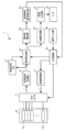
- FIG. 1 is a block diagram showing a configuration of an ultrasonic diagnostic apparatus 1 according to an embodiment of the present invention.
- the ultrasonic probe 10 transmits ultrasonic waves toward the diagnosis site of the subject and receives ultrasonic waves reflected inside the subject.
- the ultrasonic probe 10 includes m piezoelectric elements 10a as electroacoustic transducers arranged in a straight line. One-time transmission / reception of ultrasonic waves is performed using n (m> n) adjacent piezoelectric element groups selected from the m piezoelectric elements 10a. By sequentially shifting n piezoelectric element groups used for transmission / reception of ultrasonic waves, the diagnostic region in the subject is scanned with the ultrasonic beam.
- the ultrasonic probe 10 may have any scanning method such as a linear type, a convex type, and a sector type.
- Each of the piezoelectric elements 10a is connected to the multiplexer 11 via an m-channel signal line. Each of the piezoelectric elements 10 a generates an ultrasonic wave according to a drive pulse signal supplied from the transmission control unit 12 via the multiplexer 11. Each of the piezoelectric elements 10 a receives an ultrasonic wave reflected in the subject to generate a reception signal that is an electrical signal, and supplies the reception signal to the reception signal processing unit 16 via the multiplexer 11.
- the multiplexer 11 selects adjacent n piezoelectric element groups to be used for transmission / reception of ultrasonic waves from the m piezoelectric elements 10 a of the ultrasonic probe 10 in accordance with a control signal supplied from the main control unit 30. It is an electronic switch.
- the multiplexer 11 is connected to the transmission control unit 12 and the reception signal processing unit 16 via an n-channel signal line.
- the transmission control unit 12 generates drive pulse signals for n channels according to the control signal supplied from the main control unit 30. In addition, the transmission control unit 12 gives a time difference to the drive pulse signal for each channel so as to perform transmission focus for converging the ultrasonic beam to the depth position of the region of interest designated by the main control unit 30.
- the drive pulse signal generated in the transmission control unit 12 is supplied to each of the n piezoelectric elements 10 a selected by the multiplexer 11.
- the reception signal processing unit 16 has an amplifier and an A / D converter provided for each channel.
- Each of the received signals generated in the n piezoelectric elements 10a selected by the multiplexer 11 is amplified in an amplifier and converted into a digital signal by an A / D converter.
- the reception signal memory 17 is a storage medium for storing the reception signals of the respective channels converted into digital signals by the reception signal processing unit 16 as reception data.
- the phasing processing unit 18 calculates a relative time difference between the received signals based on the set sound speed supplied from the main control unit 30 so as to phase each received signal. Then, the phasing processing unit 18 gives the calculated relative time difference to the reception signals for each channel supplied from the reception signal processing unit 16 or the reception signal memory 17 to align the time phases of the reception signals for each channel.
- a phasing process that is, a reception focus process is performed. The timing at which an ultrasonic wave reflected at a certain point in the subject enters each piezoelectric element 10a does not match. This is because the propagation distance of the ultrasonic wave from the reflection point to each piezoelectric element 10a is different for each piezoelectric element.
- the phasing processing unit 18 gives a relatively long delay time to the reception signal generated by the piezoelectric element arranged at a position where the distance to the reflection point is relatively short. On the other hand, a relatively short delay time is given to the reception signal generated by the piezoelectric element arranged at a position where the distance to the reflection point is relatively long. Thereby, the phasing processing unit 18 performs phasing processing for aligning the time phases of the reception signals of the respective channels.
- the addition processing unit 20 integrates the reception signals for each channel phased by the phasing processing unit 18 to generate a phasing addition signal.
- the image generation unit 21 performs filtering processing, Log compression processing, envelope detection processing, STC (Sensitivity Time Control) processing, interpolation processing, scan conversion processing, and the like on the phasing addition signal supplied from the addition processing unit 20. Then, an image signal for constructing a so-called B-mode image obtained by converting the signal intensity of the phasing addition signal into luminance is generated.
- the monitor 22 is a display device such as a liquid crystal display panel that displays a tomographic image or the like at a diagnostic site based on the image signal generated by the image generation unit 21.
- the similarity deriving unit 23 derives a mutual similarity that is an index value indicating the similarity between received signals for each channel phased by the phasing processing unit 18 based on the set sound speed. That is, the mutual similarity is an index value indicating the similarity as a whole of the received signals for each channel phased based on the set sound speed.
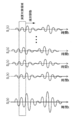
- the similarity deriving unit 23 for example, in each of a plurality of calculation target regions divided in the time axis direction of the received signal (that is, the depth direction in the imaging region), a template signal St (t) that serves as a comparison reference described later. And a correlation value between each of the received signals S1 (t) to Sn (t) for each channel (refer to FIG. 3). Then, the mutual similarity is derived for each calculation target region (for each depth region) based on the calculated correlation value.
- a template signal serving as a comparison reference for example, a signal obtained by phasing and adding reception signals of respective channels can be used.
- the time phases of the received signals of each channel are similar, and thus similar.
- the value of the mutual similarity derived by the degree deriving unit 23 increases. As the difference between the set sound speed used when phasing the received signal of each channel by the phasing processor 18 and the actual sound speed in the subject increases, the time phase shift between the received signals increases. The value of the mutual similarity derived by the similarity deriving unit 23 is low.
- the optimum set sound speed deriving unit 24 is an optimum set sound speed that is an estimated value of the actual sound speed in the subject based on the mutual similarity of the reception signal group derived for each of the plurality of set sound speeds by the similarity degree deriving unit 23. Is derived for each unit area in the imaging area corresponding to the calculation target area of the mutual similarity described above. For example, the optimum set sound speed deriving unit 24 may derive the set sound speed at which the mutual similarity of the received signal group is the highest as the optimum set sound speed in the unit region.
- the main control unit 30 controls the transmission / reception processing of the ultrasonic waves by giving control signals to the multiplexer 11, the transmission control unit 12, and the phasing processing unit 18.
- the operation input unit 40 receives various operation inputs by the user, and includes, for example, a pointing device such as a mouse or an input means such as a keyboard.
- the transmission control unit 12 received signal processing unit 16, phasing processing unit 18, addition processing unit 20, image generation unit 21, similarity derivation unit 23, optimum set sound speed derivation unit 24, and main control unit 30 are shown in FIG.
- a ROM as a recording medium storing a program describing each process in the optimum setting sound speed derivation process routine shown in FIG. 2, a CPU for executing the program, and processing contents in the CPU are temporarily stored.
- a computer equipped with a RAM or the like.
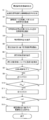
- the main control unit 30 receives this in step S1, and transmits the ultrasonic wave to the transmission control unit 12 and the multiplexer 11. A control signal for starting transmission is supplied.
- step S2 the transmission control unit 12 generates a drive pulse signal for each channel according to the control signal supplied from the main control unit 30.
- the transmission control unit 12 appropriately gives a delay time to the drive pulse signal for each channel so as to perform transmission focus on the region of interest in the subject.
- Each of the drive pulse signals generated by the transmission control unit 12 is supplied to each of the n piezoelectric elements 10 a selected by the multiplexer 11. Thereby, an ultrasonic beam is transmitted from the n piezoelectric elements 10a adjacent to the ultrasonic probe 10 into the subject.
- each piezoelectric element 10a of the ultrasonic probe 10 receives the n piezoelectric elements 10a selected by the multiplexer 11 and transmitting the ultrasonic beam.
- Each piezoelectric element 10 a generates a reception signal that is an electrical signal from the reflected echo and outputs the reception signal to the reception signal processing unit 16 via the multiplexer 11.
- the reception signal processing unit 16 performs signal processing including amplification and A / D conversion on each reception signal, and associates the reception signal subjected to signal processing with one line of reception data in association with the identification number of the line. Store in the received signal memory 17.
- the multiplexer 11 switches the piezoelectric element 10a to be selected in accordance with the control signal supplied from the main control unit 30, and shifts the piezoelectric element 10a that transmits and receives ultrasonic waves by one piezoelectric element, for example. Thereafter, transmission / reception of ultrasonic waves is performed in the same manner as described above.
- the multiplexer 11 sequentially shifts the piezoelectric elements 10a that transmit and receive ultrasonic waves, whereby the imaging region in the subject is scanned with the ultrasonic beams that are sequentially transmitted.
- the reception signals of a plurality of lines (L [1], L [2], L [3]... L [k]) corresponding to each transmission are acquired, and the reception signals of each line identify the line.
- the number is stored in the received signal memory 17 in association with the number.
- step S ⁇ b> 3 the main control unit 30 selects a line L [i] (i is a line that is a target of mutual similarity derivation processing by the similarity derivation unit 23 from the reception signals of each line stored in the reception signal memory 17. (A positive integer) received signal is selected.
- the main control unit 30 first selects the line L [1]. As a result, the reception signal of the first line acquired by the first ultrasonic transmission is used as a target for deriving the mutual similarity.
- step S4 the main control unit 30 sets the set sound speed C [j] (j is an identification number of the set sound speed and is a positive integer) used for the phasing process of the received signal performed in the phasing process unit 18.
- One is selected from a plurality of preset sound speeds. That is, the main control unit 30 has, for example, a plurality of set sound speeds C [1], C [2], C [3],... Set at 10 m / s steps in the range of 1400 m / s to 1650 m / s. Is stored in advance in a memory (not shown) provided in the device in association with the identification number of the set sound speed. Then, the main control unit 30 selects one set sound speed from among them.
- the main control unit 30 first selects the set sound speed C [1]. Thus, 1400 m / s is selected as the set sound speed value used for the phasing process.
- the set sound speed range and the step width are not limited to those described above, and can be changed as appropriate.
- step S ⁇ b> 5 the phasing processing unit 18 receives the reception signal corresponding to the line L [i] selected by the main control unit 30 in step S ⁇ b> 3 based on the control signal supplied from the main control unit 30. Read from. Next, the phasing processing unit 18 calculates the reception delay time for each channel from the set sound speed C [j] selected by the main control unit 30 in step S4 based on the control signal supplied from the main control unit 30. To do. Then, the phasing processing unit 18 performs phasing by giving the calculated reception delay time to the reception signal of each channel read from the reception signal memory 17. The phasing processing unit 18 supplies the received signal subjected to the phasing process to the similarity deriving unit 23.
- step S6 the similarity deriving unit 23 sets a calculation target region for deriving the mutual similarity for the phased reception signals of each channel.
- the calculation target area is set by cutting out the received signal in a certain time width (depth range) (see FIG. 3).
- step S7 the similarity deriving unit 23 derives the mutual similarity that is an index value of the similarity between the received signals for each channel in the calculation target region set in step S6, and uses the derived mutual similarity. Is stored in a memory (not shown).
- FIG. 3 is a waveform diagram for explaining the contents of the mutual similarity deriving process performed by the similarity deriving unit 23.
- the similarity degree deriving unit 23 generates a template signal S t (t) that serves as a comparison reference for deriving a mutual similarity degree between the received signals S 1 (t) to S n (t).
- the similarity deriving unit 23 outputs a phasing addition signal obtained by integrating the received signals S 1 (t) to S n (t) phased at the set sound speed at the same time as the template signal S t (t ).
- the similarity deriving unit 23 calculates a correlation value R i between the template signal S t (t) and the received signal S i (t) according to the following equation (1) in the calculation target region surrounded by a broken line in FIG. (Where i is an integer from 1 to n).
- the denominator is the square root of the square sum of the values of the respective points of the template signal S t (t) in the calculation target area, and each of the received signals S i (t) in the calculation target area. It is a value obtained by multiplying the square root of the integrated value of the square of the point value.
- the numerator is an integrated value of values obtained by multiplying the value of each point of the template signal S t (t) in the calculation target region by the value of each point of the received signal S i (t).
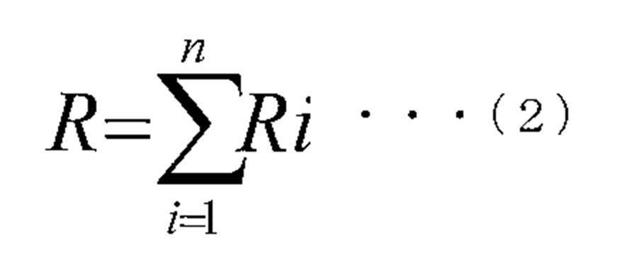
- the similarity deriving unit 23 correlates the received signals S 1 (t), S 2 (t), S 3 (t),... S n (t) and the template signal S t (t), respectively. Values R 1 , R 2 , R 3 ... R n are calculated. Then, the similarity deriving unit 23 receives the sum of the absolute values of the correlation values R i calculated for each of the reception signals S 1 (t) to S n (t) of each channel according to the following equation (2). S 1 (t) to S n (t) are derived as index values indicating the similarity between each other, that is, the mutual similarity R. The mutual similarity R derived in this way becomes higher as the set sound speed is closer to the actual sound speed in the subject.
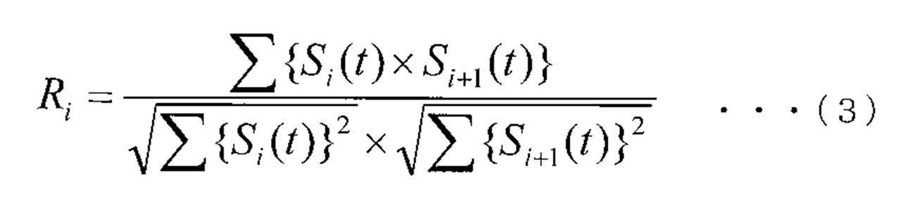
- a correlation value R i is obtained according to the following equation (3) between reception signals adjacent to each other (that is, S i (t) and S i + 1 (t)), and the sum of their absolute values is mutually similar. It may be derived as the degree R. In this case, since it is not necessary to generate the template signal S t (t), it is possible to speed up the arithmetic processing.
- step S8 the similarity deriving unit 23 determines whether or not the derivation of the mutual similarity is completed for the entire depth range (all time range) of the received signal.
- the similarity calculation unit 23 returns to step S6, shifts the calculation target region in the time axis direction (depth direction), and creates a new one.
- the calculation target area is set, and the mutual similarity is derived for the calculation target area in the same manner as described above.
- the similarity deriving unit 23 repeats the processes of steps S6 to S8 until the derivation of the mutual similarity is completed for the entire time range (total depth range) of the received signal.
- step S9 the main control unit 30 increments the identification number j of the set sound speed C [j] by one.
- step S10 the main control unit 30 compares the incremented numerical value j with the maximum value j max of the set sound speed identification number j to determine whether or not the derivation of the mutual similarity has been completed for all the set sound speeds. Determine.
- step S10 when the main control unit 30 determines that the derivation of the mutual similarity is not completed for all the set sound speeds, the process returns to step S4, a new set sound speed is set, and steps S5 to S10 are performed. Processing is performed in the same way.
- the main control unit 30 sequentially increments the identification number j of the set sound speed C [j] to receive each received signal group phased based on each set sound speed within the range of 1400 m / s to 1650 m / s. Mutual similarity between signals is derived.
- step S11 the main control unit 30 increments the identification number i of the line L [i] of the reception signal corresponding to each transmission of the ultrasonic wave by one.
- step S12 the main control unit 30 determines whether or not the derivation of the mutual similarity has been completed for all the lines by comparing the incremented numerical value i with the numerical value k indicating the maximum value of the identification number i. To do.
- step S12 when the main control unit 30 determines that the derivation of the mutual similarity is not completed for all lines, the process returns to step S3, and a new line from which the mutual similarity is derived is selected.
- the processes in steps S4 to S12 are performed in the same manner.
- the similarity deriving unit 23 stores each mutual similarity of the received signal group derived through the above-described processes in a memory (not shown) provided in the form thereof as shown in FIG. ⁇ 111 , ⁇ 112 , ⁇ 113 ,... Shown in FIG. 4 are mutual similarities in each calculation target region (each depth position) of each line derived for each set sound velocity. As shown in FIG. 4, the similarity deriving unit 23 calculates the mutual similarity in the unit area obtained by dividing the imaging area by each line and each depth position, and sets the sound speeds C [1], C [2], C [ 3].. Is derived for each of the cases where.
- step S13 the optimum setting sound speed deriving unit 24 reads the mutual similarity derived by the similarity deriving unit 23 from the memory in the similarity deriving unit 23, and performs the optimum setting in the subject based on the read mutual similarity.
- the speed of sound is derived.
- the optimum set sound speed deriving unit 24 derives the set sound speed that maximizes the mutual similarity of the received signal groups derived for each depth of each line as the optimum set sound speed at that depth position of that line.
- the optimum set sound speed deriving unit 24 supplies the optimum set sound speed derived in this way to the main control unit 30, and this routine is completed.
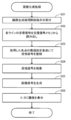
- step S ⁇ b> 21 the main control unit 30 phasing the optimum set sound speed at each depth position of each line derived by the optimum set sound speed deriving unit 24 in accordance with, for example, an operation input from the operation input unit 40 by the user. This is supplied to the processing unit 18 and the phasing processing unit 18 receives it.
- step S ⁇ b> 22 the phasing processing unit 18 reads the reception signal of each line from the reception signal memory 17.
- step S ⁇ b> 23 the phasing processing unit 18 calculates the reception delay time at each point based on the optimum set sound speed at each point derived by the optimum set sound speed deriving unit 24, and receives the received signal read from the received signal memory 17.
- the phasing process is performed by giving the calculated reception delay time to.
- the phasing processing unit 18 supplies the phased received signal to the addition processing unit 20.
- step S24 the addition processing unit 20 integrates the reception signals of the respective channels phased by the phasing processing unit 18 to generate a phasing addition signal, and supplies this to the image generation unit 21.
- step S25 the image generation unit 21 performs filtering processing, log compression processing, envelope detection processing, STC processing, interpolation processing, scan conversion processing, and the like on the phasing addition signal supplied from the addition processing unit 20, An image signal for constructing a B-mode image in which the signal intensity of the phasing addition signal is converted into luminance is generated.
- the image generation unit 21 supplies the generated image signal to the monitor 22.
- step S26 the monitor 22 displays the image signal generated by the image generation unit 21.
- the image generation processing routine is completed through the above processes.
- the ultrasonic diagnostic apparatus 1 derives the mutual similarity that is an index value of the similarity between the received signals of the respective channels phased at each set sound speed.
- the optimum set sound speed is derived based on the derived mutual similarity. That is, since the process of imaging the received signal is not required when deriving the optimum set sound speed, the optimum set sound speed can be derived in a relatively short time. Further, according to the ultrasonic diagnostic apparatus 1 according to the present embodiment, the optimum set sound speed is derived based on the mutual similarity between the reception signals of the respective channels, which is caused by ultrasonic interference in the subject.
- the ultrasonic diagnostic apparatus 1 According to the ultrasonic diagnostic apparatus 1 according to the present embodiment, an image is generated from the received signal phased using the optimum set sound speed derived with high accuracy, so a tomographic image with less distortion is generated. It becomes possible.
- the optimum set sound speed is derived for each depth position of each line, but the present invention is not limited to this.
- the optimum set sound speed deriving unit 24 calculates a sum ⁇ SUM of mutual similarities of received signals at each depth position of each line in the block in each block including a plurality of depth positions of a plurality of lines, and calculates ⁇ SUM
- the set sound speed with the largest value may be derived as the optimum set sound speed in the block.
- the set sound speed at which the mutual similarity is maximized is set as the optimum set sound speed in the part, but the present invention is not limited to this.
- the optimum set sound speed deriving unit 24 may derive a value obtained by calculating a weighted average value obtained by weighting each set sound speed by the mutual similarity of the received signals as the optimum set sound speed in the portion.
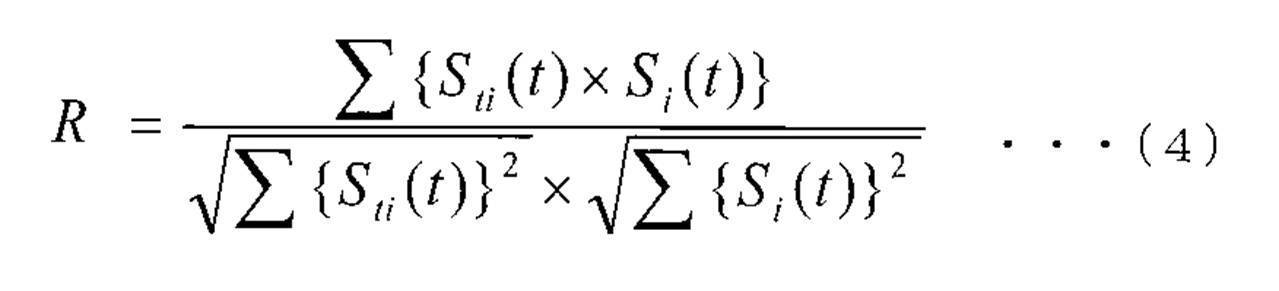
- a correlation value R may be calculated by calculating a two-dimensional correlation value according to the following equation (4).
- ⁇ represents integration with respect to t (time axis direction) and i (direction of the piezoelectric element).
- a three-dimensional correlation value may be calculated.
- the similarity deriving unit 23 performs cross-correlation calculations between the template signal St (t) and the received signals S 1 (t) to S n (t), and the presence of the peak value of the obtained cross-correlation function. to determine the phase shift amount of each of the received signals S 1 (t) ⁇ S n (t) for the template signal S t (t) from the position, the phase calculated for each received signal S 1 (t) ⁇ S n (t)
- the sum or variance of the absolute values of the deviation amounts may be derived as an index value of the similarity between the received signals. In this case, the derived value decreases as the similarity between the received signals increases.
- the similarity is derived using the received signal after the phasing process.
- the present invention is not limited to this, and the received signal of each channel is determined based on the set sound speed.
- a calculation target area centered on the reception delay time calculated for the received signal of each channel may be obtained, and a mutual similarity between the reception signals in each calculation target area may be derived.
Landscapes
- Health & Medical Sciences (AREA)
- Life Sciences & Earth Sciences (AREA)
- Engineering & Computer Science (AREA)
- Physics & Mathematics (AREA)
- Molecular Biology (AREA)
- Surgery (AREA)
- Pathology (AREA)
- Radiology & Medical Imaging (AREA)
- Biophysics (AREA)
- Biomedical Technology (AREA)
- Heart & Thoracic Surgery (AREA)
- Medical Informatics (AREA)
- Veterinary Medicine (AREA)
- Nuclear Medicine, Radiotherapy & Molecular Imaging (AREA)
- Animal Behavior & Ethology (AREA)
- General Health & Medical Sciences (AREA)
- Public Health (AREA)
- Computer Networks & Wireless Communication (AREA)
- General Physics & Mathematics (AREA)
- Radar, Positioning & Navigation (AREA)
- Remote Sensing (AREA)
- Gynecology & Obstetrics (AREA)
- Computer Vision & Pattern Recognition (AREA)
- Ultra Sonic Daignosis Equipment (AREA)
Description
本発明は、超音波の送受信によって被検体の断層画像を生成する超音波診断装置、音速導出方法およびプログラムに関する。
超音波プローブから被検体に超音波を送信し、被検体内部からの反射波に基づいて被検体の断層画像を生成する超音波診断装置が知られている。電子スキャン方式の超音波診断装置においては、超音波を送信する際には超音波プローブの各電気音響変換素子にそれらの配置に応じた遅延時間差を有する駆動パルス信号を供給して素子間で超音波の送信タイミングをずらす送信フォーカスが行われる。一方、反射波を受信する際には、各電気音響変換素子において生成された受信信号の各々に対して各電気音響変換素子の配置に応じた遅延時間を与えて各受信信号の時相を揃える受信フォーカスが行われている。これにより、超音波画像の方位分解能を向上させることができる。
超音波の送信および受信の際に各信号に与えられる遅延時間は、各電気音響変換素子から焦点までの距離と伝搬媒質の音速に基づいて設定される。伝搬媒質の音速として通常、仮定した仮定音速を用いる。しかし、伝搬媒質となる生体組織はその部位によって音速が異なるので、遅延時間を設定するために用いた仮定音速と実際の音速との間に誤差が生じると送信および受信の双方において適切に焦点を形成できずに画質劣化を招来することとなる。この課題に対して、下記の特許文献には、受信信号に基づいて実際の音速を推定して超音波画像の画質を向上させる技術が開示されている。
例えば、特開2007-7045号公報(特許文献1)には、整相加算されたエコー信号から、設定音速が相違する複数のビームプロファイルを生成し、生成した複数のビームプロファイルを同一画面に重ねて表示し、そのうち最小ビーム幅を有するものに対応する音速を生体音速として選択することが記載されている。
また、特開2001-252276号公報(特許文献2)には、平均音速に対応した遅延時間で生体内へ超音波の試し打ちを行い、その受信信号を遅延制御した各チャンネルの信号から遅延時間誤差を演算により求め、この求めたデータを予め記憶された音速をパラメータとした複数の音速の遅延時間誤差データと比較し、それらのうち一致した遅延時間誤差に応じた音速を生体内の音速として求めることが記載されている。
上記の特許文献1に記載の技術によれば、受信信号に対して複数の設定音速を用いて整相加算処理を行った後、超音波強度分布を画像化するため、処理に多大な時間を要する。
一方、特許文献2に記載の技術においては、遅延制御した各チャンネルのエコー信号から遅延時間誤差を演算により求めている。しかしながら、チャンネル間における遅延時間誤差の測定を安定的に行うことは容易ではない。すなわち、生体内に送信された超音波が干渉などによって強度低下や波形歪みを生じると、遅延時間誤差の測定精度が著しく低下する。その結果、生体内における実際の音速の推定精度が低下してしまうことになる。
本発明は、上記の点に鑑みてなされたものであり、被検体内の音速の推定値をより安定的且つ高精度に導出することができる超音波診断装置、音速導出方法およびプログラムを提供することを目的とする。
上記の目的を達成するために、本発明に係る超音波診断装置は、各々が、被検体内に送信された超音波の反射波に応じて受信信号を生成する複数の電気音響変換素子と、設定音速に基づいて導出された前記受信信号の各々の時間領域における前記受信信号相互間の類似性を示す相互類似度を、複数の設定音速毎に導出する類似度導出手段と、前記類似度導出手段によって導出された前記複数の設定音速毎の相互類似度に基づいて前記被検体内の音速の推定値を導出する音速導出手段と、を含む。
上記の超音波診断装置は、前記複数の電気音響変換素子内の複数の電気音響変換素子の各々で生成された複数の受信信号を、複数の設定音速毎に整相する整相手段を更に含み、前記類似度導出手段は、前記整相手段によって整相された受信信号相互間の相互類似度を導出するように構成されていてもよい。
前記類似度導出手段は、基準信号と、前記整相手段によって整相された受信信号の各々との相関値に基づいて前記相互類似度を導出してもよい。この場合、前記類似度導出手段は、前記基準信号と、前記整相手段によって整相された受信信号の各々との相関値を積算した値を前記相互類似度として導出してもよい。
前記基準信号は、整相された受信信号の各々を積算した整相加算信号とすることができる。
前記類似度導出手段は、前記整相手段によって整相された互いに隣接する受信信号間の相関値に基づいて前記相互類似度を導出してもよい。この場合、前記類似度導出手段は、前記整相手段によって整相された互いに隣接する受信信号間の相関値を積算した値を前記相互類似度として導出してもよい。
前記音速導出手段は、前記相互類似度が最大となる設定音速を前記被検体内の音速の推定値として導出してもよい。
前記最適設定音速導出手段は、前記相互類似度で前記設定音速の各々を重み付けして得られる重み付け平均値を前記被検体内の音速の推定値として導出してもよい。
前記整相手段が、前記音速導出手段によって導出された前記被検体内の音速の推定値に基づいて前記受信信号を整相し、加算手段が、前記整相手段によって整相された前記受信信号の各々を積算して整相加算信号を生成し、画像生成手段が、前記整相加算信号に応じた画像を生成してもよい。
また、上記の目的を達成するために、本発明に係る音速導出方法は、被検体内に送信された超音波の反射波に応じて複数の電気音響変換素子の各々で生成された複数の受信信号を、複数の設定音速毎に整相するステップと、整相された複数の受信信号内の受信信号相互間の類似性を示す相互類似度を前記複数の設定音速毎に導出するステップと、前記複数の設定音速毎の相互類似度に基づいて前記被検体内の音速の推定値を導出するステップと、を含む。
また、上記の目的を達成するために、本発明に係るプログラムは、コンピュータを被検体内に送信された超音波の反射波に応じて複数の電気音響変換素子の各々で生成された複数の受信信号を、複数の設定音速毎に整相する整相手段と、前記整相手段によって整相された複数の受信信号内の受信信号相互間の類似性を示す相互類似度を前記複数の設定音速毎に導出する類似度導出手段と、前記類似度導出手段によって導出された前記複数の設定音速毎の相互類似度に基づいて前記被検体内の音速の推定値を導出する音速導出手段と、として機能させる。
本発明に係る超音波診断装置、音速導出方法およびプログラムによれば、被検体内の音速の推定値をより安定的且つ高精度に導出することが可能となる。
以下、本発明の実施形態について図面を参照しつつ説明する。なお、各図面において、実質的に同一又は等価な構成要素又は部分には同一の参照符号を付している。
図1は、本発明の実施形態に係る超音波診断装置1の構成を示すブロック図である。
超音波プローブ10は、被検体の診断部位に向けて超音波を送信するとともに被検体の内部で反射した超音波を受信するものである。超音波プローブ10は、直線状に配列された電気音響変換素子としてのm個の圧電素子10aを含んでいる。超音波の1回の送受信は、m個の圧電素子10aの中から選択された隣接するn個(m>n)の圧電素子群を使用して行われる。超音波の送受信に使用されるn個の圧電素子群を順次シフトさせることにより、被検体内の診断部位が超音波ビームによってスキャンされる。なお、超音波プローブ10は、リニア型、コンベックス型、セクタ型等のいずれの走査方式を有するものであってもよい。圧電素子10aの各々は、mチャンネルの信号線を介してマルチプレクサ11に接続されている。圧電素子10aの各々は、送信制御部12からマルチプレクサ11を介して供給される駆動パルス信号に応じて超音波を発生させる。また、圧電素子10aの各々は、被検体内で反射された超音波を受信して電気信号である受信信号を生成し、これをマルチプレクサ11を介して受信信号処理部16に供給する。
マルチプレクサ11は、主制御部30から供給される制御信号に応じて、超音波プローブ10のm個の圧電素子10aの中から超音波の送受信に使用する隣接するn個の圧電素子群を選択する電子スイッチである。マルチプレクサ11は、nチャンネルの信号線を介して送信制御部12および受信信号処理部16に接続されている。
送信制御部12は、主制御部30から供給される制御信号に応じて、nチャンネル分の駆動パルス信号を生成する。また、送信制御部12は、主制御部30によって指定された着目領域の深さ位置に超音波ビームを収束させる送信フォーカスを実施するべくチャンネル毎の駆動パルス信号に時間差を付与する。送信制御部12において生成された駆動パルス信号は、マルチプレクサ11によって選択されたn個の圧電素子10aの各々に供給される。
受信信号処理部16は、チャンネル毎に設けられた増幅器およびA/D変換器を有する。マルチプレクサ11によって選択されたn個の圧電素子10aにおいて生成された受信信号の各々は、増幅器において増幅され、A/D変換器によってデジタル信号に変換される。
受信信号メモリ17は、受信信号処理部16によってデジタル信号に変換された各チャンネルの受信信号を受信データとして記憶する記憶媒体である。
整相処理部18は、各受信信号を整相するべく主制御部30から供給される設定音速に基づいて受信信号間の相対的な時間差を算出する。そして、整相処理部18は、受信信号処理部16または受信信号メモリ17から供給されるチャンネル毎の受信信号に、算出した相対的な時間差を与えることによりチャンネル毎の受信信号の時相を揃える整相処理、すなわち受信フォーカス処理を行う。被検体内のある点で反射された超音波が各圧電素子10aに入射するタイミングは一致しない。これは、反射点から各圧電素子10aに至る超音波の伝搬距離が圧電素子毎に相違するからである。整相処理部18は、反射点までの距離が比較的短い位置に配置された圧電素子が生成する受信信号に対して比較的長い遅延時間を与える。一方、反射点までの距離が比較的長い位置に配置された圧電素子が生成する受信信号に対して比較的短い遅延時間を与える。これにより、整相処理部18は、各チャンネルの受信信号の時相を揃える整相処理を行う。
加算処理部20は、整相処理部18によって整相されたチャンネル毎の受信信号を積算して整相加算信号を生成する。
画像生成部21は、加算処理部20から供給される整相加算信号に対してフィルタリング処理、Log圧縮処理、包絡線検波処理、STC(Sensitivity Time Control)処理、補間処理及び走査変換処理などを施し、整相加算信号の信号強度を輝度に変換した所謂Bモード画像を構築するための画像信号を生成する。
モニタ22は、画像生成部21によって生成された画像信号に基づいて診断部位における断層画像等を表示する液晶表示パネル等の表示装置である。
類似度導出部23は、整相処理部18が設定音速に基づいて整相したチャンネル毎の受信信号相互間の類似性を示す指標値である相互類似度を導出する。すなわち、相互類似度とは、設定音速に基づいて整相されたチャンネル毎の受信信号の全体としての類似性を示す指標値である。類似度導出部23は、例えば、受信信号の時間軸方向(すなわち、撮像領域における深さ方向)において分割された複数の演算対象領域の各々において、後述する比較基準となるテンプレート信号St(t)とチャンネル毎の受信信号S1(t)~Sn(t)(共に図3参照)の各々との相関値を算出する。そして、算出した相関値に基づいて演算対象領域毎(深さ領域毎)に相互類似度を導出する。比較基準となるテンプレート信号は、例えば、各チャンネルの受信信号を整相加算したものを用いることができる。
類似度導出部23は、整相処理部18が設定音速に基づいて整相したチャンネル毎の受信信号相互間の類似性を示す指標値である相互類似度を導出する。すなわち、相互類似度とは、設定音速に基づいて整相されたチャンネル毎の受信信号の全体としての類似性を示す指標値である。類似度導出部23は、例えば、受信信号の時間軸方向(すなわち、撮像領域における深さ方向)において分割された複数の演算対象領域の各々において、後述する比較基準となるテンプレート信号St(t)とチャンネル毎の受信信号S1(t)~Sn(t)(共に図3参照)の各々との相関値を算出する。そして、算出した相関値に基づいて演算対象領域毎(深さ領域毎)に相互類似度を導出する。比較基準となるテンプレート信号は、例えば、各チャンネルの受信信号を整相加算したものを用いることができる。
整相処理部18が各チャンネルの受信信号を整相する際に用いる設定音速が被検体内の実際の音速と略一致している場合には、各チャンネルの受信信号の時相が揃うので類似度導出部23において導出される相互類似度の値は高くなる。整相処理部18が各チャンネルの受信信号を整相する際に用いた設定音速と被検体内の実際の音速との差が大きくなるに従って、受信信号間で時相のずれが大きくなるので、類似度導出部23において導出される相互類似度の値は低くなる。
最適設定音速導出部24は、類似度導出部23において複数の設定音速の各々について導出された受信信号群の相互類似度に基づいて、被検体内における実際の音速の推定値である最適設定音速を、上記した相互類似度の演算対象領域に対応する撮像領域内の単位領域毎に導出する。最適設定音速導出部24は、例えば、受信信号群の相互類似度が最も高くなる設定音速を当該単位領域における最適設定音速として導出してもよい。
最適設定音速導出部24は、類似度導出部23において複数の設定音速の各々について導出された受信信号群の相互類似度に基づいて、被検体内における実際の音速の推定値である最適設定音速を、上記した相互類似度の演算対象領域に対応する撮像領域内の単位領域毎に導出する。最適設定音速導出部24は、例えば、受信信号群の相互類似度が最も高くなる設定音速を当該単位領域における最適設定音速として導出してもよい。
主制御部30は、マルチプレクサ11、送信制御部12および整相処理部18に制御信号を与えることにより超音波の送受信処理を統括的に制御する。
操作入力部40は、ユーザによる各種の操作入力を受け付けるものであり、例えば、マウスなどのポインティングデバイスやキーボードなどの入力手段によって構成されるものである。
なお、送信制御部12、受信信号処理部16、整相処理部18、加算処理部20、画像生成部21、類似度導出部23、最適設定音速導出部24、主制御部30は、図2に示される後述の最適設定音速導出処理ルーチンにおける各処理を記述したプログラムを格納した記録媒体としてのROMと、このプログラムを実行するためのCPUと、CPUにおける処理内容を一時的に記憶しておくためのRAM等を備えたコンピュータで構成され得る。
次に、本実施形態に係る超音波診断装置1が、被検体内の最適設定音速を導出する処理について図2に示すフローチャートを参照しつつ説明する。
ユーザが操作入力部40から被検体内における最適設定音速の導出処理を開始させる操作を行うと、ステップS1において、主制御部30はこれを受信し、送信制御部12およびマルチプレクサ11に超音波の送信を開始させるための制御信号を供給する。
ステップS2において、送信制御部12は、主制御部30から供給される制御信号に応じて各チャンネル毎に駆動パルス信号を生成する。送信制御部12は、被検体内の着目領域に送信フォーカスを実施するべくチャンネル毎の駆動パルス信号に適宜遅延時間を与える。送信制御部12によって生成された駆動パルス信号の各々は、マルチプレクサ11によって選択されたn個の圧電素子10aにそれぞれ供給される。これにより、超音波プローブ10の隣接するn個の圧電素子10aから被検体内に向けて超音波ビームが送信される。
超音波プローブ10の各圧電素子10aから送信された超音波の反射によるエコーは、マルチプレクサ11によって選択され超音波ビームを送信したn個の圧電素子10aによって受信される。各圧電素子10aは、反射エコーから電気信号である受信信号を生成してこれをマルチプレクサ11を介して受信信号処理部16に出力する。受信信号処理部16は、各受信信号に対して増幅およびA/D変換を含む信号処理を施し、信号処理を施した受信信号を1ライン分の受信データとして当該ラインの識別ナンバーと対応付けて受信信号メモリ17に格納する。
その後、マルチプレクサ11は、主制御部30から供給される制御信号に応じて選択対象となる圧電素子10aの切り替えを行ない、超音波の送受信を行う圧電素子10aを例えば圧電素子1つ分シフトさせる。その後、上記と同様に超音波の送受信が行われる。マルチプレクサ11が超音波の送受信を行う圧電素子10aを順次シフトさせることにより、被検体内における撮像領域が順次送信される超音波ビームによってスキャンされる。これにより、各送信に対応する複数ライン(L[1]、L[2]、L[3]・・・L[k])の受信信号が取得され、各ラインの受信信号が当該ラインの識別ナンバーと対応付けられて受信信号メモリ17に格納される。
ステップS3において、主制御部30は、受信信号メモリ17に格納された各ラインの受信信号のうち、類似度導出部23による相互類似度の導出処理対象となるラインL[i](iはラインの識別ナンバーであり正の整数)の受信信号を選択する。主制御部30は、初めにラインL[1]を選択する。これにより、第1回目の超音波の送信によって取得された第1ライン目の受信信号が相互類似度の導出の対象とされる。
ステップS4において、主制御部30は、整相処理部18において行われる受信信号の整相処理に使用される設定音速C[j](jは設定音速の識別ナンバーであり正の整数)を、予め定められた複数の設定音速の中からから1つ選択する。すなわち、主制御部30は、例えば、1400m/s~1650m/sの範囲において10m/sステップで設定された複数の設定音速C[1]、C[2]、C[3]、・・・を当該設定音速の識別ナンバーに対応付けて自身に備えるメモリ(図示せず)に予め保持している。そして、主制御部30は、その中から1の設定音速を選択する。主制御部30は、初めに設定音速C[1]を選択する。これにより整相処理に使用される設定音速値として1400m/sが選択される。なお、設定音速の範囲やステップの幅は、上記したものに限定されるものではなく、適宜変更することが可能である。
ステップS5において、整相処理部18は、主制御部30から供給される制御信号に基づいてステップS3において主制御部30によって選択されたラインL[i]に対応する受信信号を受信信号メモリ17から読み出す。次に、整相処理部18は、主制御部30から供給される制御信号に基づいてステップS4において主制御部30によって選択された設定音速C[j]から各チャンネル毎の受信遅延時間を算出する。そして、整相処理部18は、受信信号メモリ17から読み出した各チャンネルの受信信号に算出した受信遅延時間を与えることにより整相する。整相処理部18は、整相処理された受信信号を類似度導出部23に供給する。
ステップS6において、類似度導出部23は、整相された各チャンネルの受信信号について相互類似度の導出を行う演算対象領域を設定する。演算対象領域は、受信信号をある時間幅(深さ範囲)で切り出すことにより設定される(図3参照)。
ステップS7において、類似度導出部23は、ステップS6において設定された演算対象領域においてチャンネル毎の受信信号相互間の類似性の指標値である相互類似度を導出し、導出した相互類似度を自身に備えるメモリ(図示せず)に記憶する。図3は、類似度導出部23によって行われる相互類似度の導出処理の内容を説明するための波形図である。
図3において、整相処理部18において整相処理された選択されたラインにおける各チャンネルの受信信号S1(t)~Sn(t)が示されている。類似度導出部23は、受信信号S1(t)~Sn(t)相互間の相互類似度を導出するための比較基準となるテンプレート信号St(t)を生成する。類似度導出部23は、当該設定音速にて整相した受信信号S1(t)~Sn(t)を同一時間毎に積算することにより得られる整相加算信号をテンプレート信号St(t)として用いることとしてもよい。
類似度導出部23は、図3において破線で囲まれた演算対象領域において、テンプレート信号St(t)と受信信号Si(t)との相関値Riを下記の式(1)に従って算出する(但しiは1~nの整数である)。式(1)において、分母は、演算対象領域内におけるテンプレート信号St(t)の各点の値の2乗の積算値の平方根と、演算対象領域内における受信信号Si(t)の各点の値の2乗の積算値の平方根とを乗算した値である。分子は、演算対象領域内におけるテンプレート信号St(t)の各点の値と受信信号Si(t)の各点の値とを乗算した値の積算値である。

類似度導出部23は、受信信号S1(t)、S2(t)、S3(t)、・・・Sn(t)とテンプレート信号St(t)との間でそれぞれ、相関値R1、R2、R3・・・Rnを算出する。そして、類似度導出部23は、下記の式(2)に従って、各チャンネルの受信信号S1(t)~Sn(t)の各々について算出した相関値Riの絶対値の総和を受信信号S1(t)~Sn(t)相互間の類似性を示す指標値、すなわち相互間類似度Rとして導出する。このようにして導出される相互類似度Rは、設定音速が被検体内の実際の音速に近いほど高い値となる。
なお、上記の例では、テンプレート信号St(t)と各チャンネルの受信信号S1(t)~Sn(t)との間でそれぞれ相関値を算出して相互類似度Rを求める方法を示したが、これに限定されるものではない。例えば、互いに隣り合う受信信号間(すなわち、Si(t)とSi+1(t))で、相関値Riを下記の式(3)に従ってそれぞれ求めて、それらの絶対値の総和を相互類似度Rとして導出することとしてもよい。この場合、テンプレート信号St(t)を生成することを要しないので、演算処理の高速化が可能となる。
ステップS8において、類似度導出部23は、受信信号の全深さ範囲(全時間範囲)について相互類似度の導出が完了したか否かを判定する。類似度算出部23は、本ステップにおいて相互類似度の導出が完了していないと判定した場合には、ステップS6に戻り、演算対象領域を時間軸方向(深さ方向)にシフトさせ、新たな演算対象領域を設定して当該演算対象領域について上記と同様に相互類似度を導出する。類似度導出部23は、受信信号の全時間範囲(全深さ範囲)について相互類似度の導出が完了するまでステップS6~S8の処理を繰り返す。
ステップS9において、主制御部30は、設定音速C[j]の識別ナンバーjを1つインクリメントする。ステップS10において、主制御部30は、インクリメントされた数値jと設定音速の識別ナンバーjの最大値jmaxとを比較することにより、全ての設定音速について相互類似度の導出が完了したか否かを判定する。ステップS10において、主制御部30が全ての設定音速について相互類似度の導出が完了していないと判定した場合、処理はステップS4に戻され、新たな設定音速が設定され、ステップS5~S10の処理が同様に行われる。主制御部30が設定音速C[j]の識別ナンバーjを順次インクリメントすることにより、1400m/s~1650m/sの範囲内における各設定音速に基づいて整相された受信信号群の各々について受信信号相互間の相互類似度が導出される。
ステップS11において、主制御部30は、超音波の各送信に対応する受信信号のラインL[i]の識別ナンバーiを1つインクリメントする。ステップS12において、主制御部30は、インクリメントされた数値iと識別ナンバーiの最大値を示す数値kとを比較することにより、全てのラインについて相互類似度の導出が完了したか否かを判定する。ステップS12において、主制御部30が全てのラインについて相互類似度の導出が完了していないと判定した場合、処理はステップS3に戻され、相互類似度の導出対象となる新たなラインが選択され、ステップS4~S12の処理が同様に行われる。主制御部30がラインL[i]の識別ナンバーiを順次インクリメントすることにより、各ラインの受信信号について、上記と同様に設定音速毎および演算対象領域毎に相互類似度が導出される。
類似度導出部23は、上記の各処理を経ることにより導出した受信信号群の相互類似度の各々を図4に示すような形態で自身に備えるメモリ(図示せず)に記憶する。図4に示されるα111、α112、α113、・・・は、設定音速毎に導出された各ラインの各演算対象領域(各深さ位置)における相互類似度である。図4に示すように、類似度導出部23は、撮像領域を各ラインおよび各深さ位置で分割した単位領域における相互類似度を、各設定音速C[1]、C[2]、C[3]・・・が設定された場合の各々について導出する。
類似度導出部23は、上記の各処理を経ることにより導出した受信信号群の相互類似度の各々を図4に示すような形態で自身に備えるメモリ(図示せず)に記憶する。図4に示されるα111、α112、α113、・・・は、設定音速毎に導出された各ラインの各演算対象領域(各深さ位置)における相互類似度である。図4に示すように、類似度導出部23は、撮像領域を各ラインおよび各深さ位置で分割した単位領域における相互類似度を、各設定音速C[1]、C[2]、C[3]・・・が設定された場合の各々について導出する。
ステップS13において、最適設定音速導出部24は、類似度導出部23によって導出された相互類似度を類似度導出部23内のメモリから読み出し、読み出した相互類似度に基づいて被検体内の最適設定音速を導出する。例えば、最適設定音速導出部24は、各ラインの各深さについて導出された受信信号群の相互類似度が最大となる設定音速をそのラインのその深さ位置における最適設定音速として導出する。
最適設定音速導出部24は、このようにして導出された最適設定音速を主制御部30に供給して本ルーチンが終了する。
以下に、撮像領域内の各部位毎に導出された最適設定音速を利用した画像生成処理の一例について図5に示すフローチャートを参照しつつ説明する。
ステップS21において、主制御部30は、例えば、ユーザによる操作入力部40からの操作入力に応じて、最適設定音速導出部24によって導出された各ラインの各深さ位置における最適設定音速を整相処理部18に供給し、整相処理部18はこれを受信する。
ステップS22において、整相処理部18は、受信信号メモリ17から各ラインの受信信号を読み出す。
ステップS23において、整相処理部18は、最適設定音速導出部24によって導出された各点における最適設定音速に基づいて、各点における受信遅延時間を算出し、受信信号メモリ17から読み出した受信信号に算出した受信遅延時間を与えて整相処理を行う。整相処理部18は、整相した受信信号を加算処理部20に供給する。
ステップS24において、加算処理部20は、整相処理部18によって整相された各チャンネルの受信信号を積算して整相加算信号を生成し、これを画像生成部21に供給する。
ステップS25において、画像生成部21は、加算処理部20から供給された整相加算信号に対してフィルタリング処理、Log圧縮処理、包絡線検波処理、STC処理、補間処理、走査変換処理などを施し、整相加算信号の信号強度を輝度に変換したBモード画像を構築するための画像信号を生成する。画像生成部21は、生成した画像信号をモニタ22に供給する。
ステップS26において、モニタ22は、画像生成部21によって生成された画像信号を表示する。
以上の各処理を経ることにより、本画像生成処理ルーチンが終了する。
以上の説明から明らかなように、本実施形態に係る超音波診断装置1は、各設定音速で整相された各チャンネルの受信信号相互間の類似性の指標値である相互類似度を導出し、導出した相互類似度に基づいて最適設定音速を導出する。すなわち、最適設定音速を導出する際に、受信信号を画像化する処理を要しないので、比較的短時間で最適設定音速を導出することが可能となる。また、本実施形態に係る超音波診断装置1によれば、各チャンネルの受信信号相互間の相互類似度に基づいて最適設定音速を導出するので、被検体内における超音波の干渉などに起因して受信信号の強度低下や波形歪みが生じた場合でも、相互類似度自体が大きく変動しないため、比較的安定的に最適設定音速を導出することが可能となり、最適設定音速の導出精度を高めることが可能となる。すなわち、最適設定音速と実際の音速との誤差を小さくすることができる。また、本実施形態に係る超音波診断装置1によれば、高い精度で導出された最適設定音速を用いて整相された受信信号から画像が生成されるので、歪みの少ない断層画像を生成することが可能となる。
なお、上記の実施形態では、各ラインの各深さ位置について最適設定音速を導出することとしたがこれに限定されるものではない。最適設定音速導出部24は、複数ラインの複数深さ位置からなる各ブロックにおいて、当該ブロック内における各ラインの各深さ位置の受信信号の相互類似度の総和αSUMを算出し、αSUMの値が最も大きくなる設定音速を当該ブロックにおける最適設定音速として導出することとしてもよい。
また、上記の実施形態では、相互類似度が最大となる設定音速を当該部位における最適設定音速とすることとしたが、これに限定されるものではない。最適設定音速導出部24は、受信信号の相互類似度で各設定音速を重み付けした重み付け平均値を算出して得た値を当該部位における最適設定音速として導出することとしてもよい。
また、上記の説明では、類似度導出部23がテンプレート信号と各チャンネルの受信信号との間で1次元の相関値を算出する場合を例示したが、これに限定されるものではない。類似度算出部23は、テンプレート信号を圧電素子の方向と時間軸方向(深さ方向)の2次元信号に展開して2次元の相関値を算出することとしてもよい。つまり、テンプレート信号St(t)を各チャンネルの受信信号に対応して並べた2次元的なテンプレート信号St1(1)、St2(t)、・・・、Stn(t)を生成し(ここで、St1(t)=St2(t)=・・・=Stn(t))、これと各チャンネルの受信信号S1(t)~Sn(t)との間で下記の式(4)に従って2次元的な相関値を算出して相関値Rとしてもよい。ここでΣはt(時間軸方向)とi(圧電素子の方向)に関する積算を示す。
また、3次元プローブを用いる場合には、3次元の相関値を算出することとしてもよい。
また、類似度導出部23は、テンプレート信号St(t)と各受信信号S1(t)~Sn(t)との相互相関演算をそれぞれ行い、求められた相互相関関数のピーク値の存在する位置からテンプレート信号St(t)に対する各受信信号S1(t)~Sn(t)の位相ずれ量を求め、各受信信号S1(t)~Sn(t)について求めた位相ずれ量の絶対値の総和または分散を受信信号相互間の類似性の指標値として導出することとしてもよい。この場合、受信信号相互間の類似性が高くなるほど、導出される値は小さくなる。
また、上記の実施形態では、整相処理を施した後の受信信号を用いて類似度を導出することとしたがこれに限定されるものではなく、設定音速に基づいて各チャンネルの受信信号に対して算出された受信遅延時間を中心とする演算対象領域を各チャンネルの受信信号について求め、各演算対象領域内における受信信号間の相互類似度を導出してもよい。
日本出願特願2012-120242号の開示はその全体が参照により本明細書に取り込まれる。
本明細書に記載された全ての文献、特許出願、および技術規格は、個々の文献、特許出願、および技術規格が参照により取り込まれることが具体的かつ個々に記された場合と同程度に、本明細書中に参照により取り込まれる。
Claims (12)
- 各々が、被検体内に送信された超音波の反射波に応じて受信信号を生成する複数の電気音響変換素子と、
設定音速に基づいて導出された前記受信信号の各々の時間領域における前記受信信号相互間の類似性を示す相互類似度を、複数の設定音速毎に導出する類似度導出手段と、
前記類似度導出手段によって導出された前記複数の設定音速毎の相互類似度に基づいて前記被検体内の音速の推定値を導出する音速導出手段と、
を含む超音波診断装置。 - 前記複数の電気音響変換素子内の複数の電気音響変換素子の各々で生成された複数の受信信号を、複数の設定音速毎に整相する整相手段を更に含み、
前記類似度導出手段は、前記整相手段によって整相された受信信号相互間の相互類似度を導出する請求項1に記載の超音波診断装置。 - 前記類似度導出手段は、基準信号と、前記整相手段によって整相された受信信号の各々との相関値に基づいて前記相互類似度を導出する請求項2に記載の超音波診断装置。
- 前記類似度導出手段は、前記基準信号と、前記整相手段によって整相された受信信号の各々との相関値を積算した値を前記相互類似度として導出する請求項3に記載の超音波診断装置。
- 前記基準信号は、整相された受信信号の各々を積算した整相加算信号である請求項3または4に記載の超音波診断装置。
- 前記類似度導出手段は、前記整相手段によって整相された互いに隣接する受信信号間の相関値に基づいて前記相互類似度を導出する請求項2に記載の超音波診断装置。
- 前記類似度導出手段は、前記整相手段によって整相された互いに隣接する受信信号間の相関値を積算した値を前記相互類似度として導出する請求項6に記載の超音波診断装置。
- 前記音速導出手段は、前記相互類似度が最大となる設定音速を前記被検体内の音速の推定値として導出する請求項1乃至7のいずれか1項に記載の超音波診断装置。
- 前記最適設定音速導出手段は、前記相互類似度で前記設定音速の各々を重み付けして得られる重み付け平均値を前記被検体内の音速の推定値として導出する請求項1乃至7のいずれか1項に記載の超音波診断装置。
- 前記整相手段が、前記音速導出手段によって導出された前記被検体内の音速の推定値に基づいて前記受信信号を整相し、
加算手段が、前記整相手段によって整相された前記受信信号の各々を積算して整相加算信号を生成し、
画像生成手段が、前記整相加算信号に応じた画像を生成する請求項2乃至9のいずれか1項に記載の超音波診断装置。 - 被検体内に送信された超音波の反射波に応じて複数の電気音響変換素子の各々で生成された複数の受信信号を、複数の設定音速毎に整相するステップと、
整相された複数の受信信号内の受信信号相互間の類似性を示す相互類似度を前記複数の設定音速毎に導出するステップと、
前記複数の設定音速毎の相互類似度に基づいて前記被検体内の音速の推定値を導出するステップと、
を含む音速導出方法。 - コンピュータを
被検体内に送信された超音波の反射波に応じて複数の電気音響変換素子の各々で生成された複数の受信信号を、複数の設定音速毎に整相する整相手段と、
前記整相手段によって整相された複数の受信信号内の受信信号相互間の類似性を示す相互類似度を前記複数の設定音速毎に導出する類似度導出手段と、
前記類似度導出手段によって導出された前記複数の設定音速毎の相互類似度に基づいて前記被検体内の音速の推定値を導出する音速導出手段と、
として機能させるためのプログラム。
Priority Applications (2)
| Application Number | Priority Date | Filing Date | Title |
|---|---|---|---|
| CN201380025998.4A CN104302231A (zh) | 2012-05-25 | 2013-05-23 | 超声波诊断装置、声速导出方法及程序 |
| US14/535,316 US10349920B2 (en) | 2012-05-25 | 2014-11-06 | Ultrasound diagnostic device, sound velocity derivation method and program |
Applications Claiming Priority (2)
| Application Number | Priority Date | Filing Date | Title |
|---|---|---|---|
| JP2012120242A JP5925599B2 (ja) | 2012-05-25 | 2012-05-25 | 超音波診断装置、音速導出方法およびプログラム |
| JP2012-120242 | 2012-05-25 |
Related Child Applications (1)
| Application Number | Title | Priority Date | Filing Date |
|---|---|---|---|
| US14/535,316 Continuation US10349920B2 (en) | 2012-05-25 | 2014-11-06 | Ultrasound diagnostic device, sound velocity derivation method and program |
Publications (1)
| Publication Number | Publication Date |
|---|---|
| WO2013176228A1 true WO2013176228A1 (ja) | 2013-11-28 |
Family
ID=49623909
Family Applications (1)
| Application Number | Title | Priority Date | Filing Date |
|---|---|---|---|
| PCT/JP2013/064397 Ceased WO2013176228A1 (ja) | 2012-05-25 | 2013-05-23 | 超音波診断装置、音速導出方法およびプログラム |
Country Status (4)
| Country | Link |
|---|---|
| US (1) | US10349920B2 (ja) |
| JP (1) | JP5925599B2 (ja) |
| CN (1) | CN104302231A (ja) |
| WO (1) | WO2013176228A1 (ja) |
Citations (3)
| Publication number | Priority date | Publication date | Assignee | Title |
|---|---|---|---|---|
| JPH09224938A (ja) * | 1996-02-23 | 1997-09-02 | Toshiba Corp | 超音波診断装置及び遅延時間最適化方法 |
| JP2008264531A (ja) * | 2007-03-28 | 2008-11-06 | Toshiba Corp | 超音波イメージング装置及び超音波速度最適化プログラム |
| JP2012071042A (ja) * | 2010-09-29 | 2012-04-12 | Fujifilm Corp | 超音波画像診断装置、超音波画像生成方法およびプログラム |
Family Cites Families (8)
| Publication number | Priority date | Publication date | Assignee | Title |
|---|---|---|---|---|
| US4835689A (en) * | 1987-09-21 | 1989-05-30 | General Electric Company | Adaptive coherent energy beam formation using phase conjugation |
| US5415173A (en) * | 1993-02-23 | 1995-05-16 | Hitachi, Ltd. | Ultrasound diagnosis system |
| US5741979A (en) * | 1995-11-09 | 1998-04-21 | The United States Of America As Represented By The Administrator Of National Aeronautics And Space Adminstrator | Particle velocity measuring system |
| JP4416256B2 (ja) | 2000-03-10 | 2010-02-17 | 株式会社日立メディコ | 超音波撮像装置 |
| US20060100666A1 (en) * | 2000-04-20 | 2006-05-11 | Pulmosonix Pty. Ltd. | Apparatus and method for lung analysis |
| JP4958348B2 (ja) * | 2001-09-06 | 2012-06-20 | 株式会社日立メディコ | 超音波撮像装置 |
| JP4817728B2 (ja) | 2005-06-29 | 2011-11-16 | 株式会社東芝 | 超音波診断装置 |
| JP5108444B2 (ja) * | 2007-10-11 | 2012-12-26 | 富士フイルム株式会社 | 超音波診断方法及び装置 |
-
2012
- 2012-05-25 JP JP2012120242A patent/JP5925599B2/ja not_active Expired - Fee Related
-
2013
- 2013-05-23 WO PCT/JP2013/064397 patent/WO2013176228A1/ja not_active Ceased
- 2013-05-23 CN CN201380025998.4A patent/CN104302231A/zh active Pending
-
2014
- 2014-11-06 US US14/535,316 patent/US10349920B2/en not_active Expired - Fee Related
Patent Citations (3)
| Publication number | Priority date | Publication date | Assignee | Title |
|---|---|---|---|---|
| JPH09224938A (ja) * | 1996-02-23 | 1997-09-02 | Toshiba Corp | 超音波診断装置及び遅延時間最適化方法 |
| JP2008264531A (ja) * | 2007-03-28 | 2008-11-06 | Toshiba Corp | 超音波イメージング装置及び超音波速度最適化プログラム |
| JP2012071042A (ja) * | 2010-09-29 | 2012-04-12 | Fujifilm Corp | 超音波画像診断装置、超音波画像生成方法およびプログラム |
Also Published As
| Publication number | Publication date |
|---|---|
| CN104302231A (zh) | 2015-01-21 |
| US20150065880A1 (en) | 2015-03-05 |
| JP2013244221A (ja) | 2013-12-09 |
| JP5925599B2 (ja) | 2016-05-25 |
| US10349920B2 (en) | 2019-07-16 |
Similar Documents
| Publication | Publication Date | Title |
|---|---|---|
| JP4795675B2 (ja) | 医療用超音波システム | |
| EP1426010B1 (en) | Ultrasonographic apparatus, ultrasonographic data processing method, and ultrasonographic data processing program | |
| KR101922522B1 (ko) | 전단파들을 사용하는 사운드 스피드 이미징 | |
| US9310472B2 (en) | Focal point information determination method and apparatus, and ambient sound velocity obtaining method and apparatus | |
| JP2009268622A (ja) | 超音波測定装置 | |
| JP2010119481A (ja) | 超音波診断装置 | |
| WO2017033502A1 (ja) | 超音波診断装置および超音波診断装置の制御方法 | |
| JP5467922B2 (ja) | 超音波診断装置 | |
| CN111388012B (zh) | 用于检测组织硬度的方法、设备及系统 | |
| WO2014103512A1 (ja) | 軟組織軟骨境界面検出方法、軟組織軟骨境界面検出装置、および軟組織軟骨境界面検出プログラム | |
| KR20200030463A (ko) | 초음파-기반 전단파 이미징을 위한 각도들 | |
| JP2015136449A (ja) | 超音波診断装置及びビームフォーミング方法 | |
| JP5869411B2 (ja) | 超音波診断装置および超音波画像生成方法 | |
| JP5663552B2 (ja) | 超音波検査装置、超音波検査装置の信号処理方法およびプログラム | |
| JP5854929B2 (ja) | 超音波診断装置、設定音速の信頼性判定方法およびプログラム | |
| KR20120067535A (ko) | 미드 포인트 알고리즘에 기초하여 hprf 도플러 영상을 제공하는 초음파 시스템 및 방법 | |
| KR101551469B1 (ko) | 평면파를 이용한 초음파 송수신집속 방법 및 시스템 | |
| US10492762B2 (en) | Ultrasound diagnostic device, ultrasound diagnostic method, and program | |
| US20180214135A1 (en) | Sound speed calculation system and sound speed calculation method | |
| JP4537280B2 (ja) | 超音波診断装置 | |
| JP5925599B2 (ja) | 超音波診断装置、音速導出方法およびプログラム | |
| US20220022849A1 (en) | Ultrasound diagnostic apparatus, control method of ultrasound diagnostic apparatus, and processor for ultrasound diagnostic apparatus | |
| US20120197125A1 (en) | Ultrasound diagnostic device | |
| JP5901431B2 (ja) | 超音波診断装置、音速導出方法およびプログラム | |
| JP2013244220A (ja) | 超音波診断装置、音速導出方法およびプログラム |
Legal Events
| Date | Code | Title | Description |
|---|---|---|---|
| 121 | Ep: the epo has been informed by wipo that ep was designated in this application |
Ref document number: 13793846 Country of ref document: EP Kind code of ref document: A1 |
|
| NENP | Non-entry into the national phase |
Ref country code: DE |
|
| 122 | Ep: pct application non-entry in european phase |
Ref document number: 13793846 Country of ref document: EP Kind code of ref document: A1 |