WO2013168710A1 - Guide device - Google Patents
Guide device Download PDFInfo
- Publication number
- WO2013168710A1 WO2013168710A1 PCT/JP2013/062851 JP2013062851W WO2013168710A1 WO 2013168710 A1 WO2013168710 A1 WO 2013168710A1 JP 2013062851 W JP2013062851 W JP 2013062851W WO 2013168710 A1 WO2013168710 A1 WO 2013168710A1
- Authority
- WO
- WIPO (PCT)
- Prior art keywords
- magnetic field
- permanent magnet
- magnetic
- magnetic fluid
- capsule endoscope
- Prior art date
Links
Images


Classifications
-
- A—HUMAN NECESSITIES
- A61—MEDICAL OR VETERINARY SCIENCE; HYGIENE
- A61B—DIAGNOSIS; SURGERY; IDENTIFICATION
- A61B1/00—Instruments for performing medical examinations of the interior of cavities or tubes of the body by visual or photographical inspection, e.g. endoscopes; Illuminating arrangements therefor
- A61B1/00147—Holding or positioning arrangements
- A61B1/00158—Holding or positioning arrangements using magnetic field
-
- A—HUMAN NECESSITIES
- A61—MEDICAL OR VETERINARY SCIENCE; HYGIENE
- A61B—DIAGNOSIS; SURGERY; IDENTIFICATION
- A61B1/00—Instruments for performing medical examinations of the interior of cavities or tubes of the body by visual or photographical inspection, e.g. endoscopes; Illuminating arrangements therefor
- A61B1/04—Instruments for performing medical examinations of the interior of cavities or tubes of the body by visual or photographical inspection, e.g. endoscopes; Illuminating arrangements therefor combined with photographic or television appliances
- A61B1/041—Capsule endoscopes for imaging
Abstract
Provided is a guide device equipped with a permanent magnet having a shape with which it is possible to generate a magnetic field suitable for guiding a capsule-type medical device. A guide device for guiding a capsule-type endoscope (10), which has a first permanent magnet in the interior, in a body to be examined by applying a magnetic field to the capsule-type endoscope (10) while the capsule-type endoscope (10) is injected into the body to be examined. The guide device is provided with a second permanent magnet which functions as an extracorporeal permanent magnet (25a) disposed on the outside of the body to be examined, has a first surface containing a magnetization direction and a first direction that is orthogonal to the magnetization direction, and constrains the capsule-type endoscope (10) within a region facing the first surface. The length of the extracorporeal permanent magnet (25a) in the first direction is longer than the length thereof in the magnetization direction.
Description
本発明は、被検体内に導入されたカプセル型医療装置を誘導する誘導装置に関する。
The present invention relates to a guiding device for guiding a capsule medical device introduced into a subject.
従来、内視鏡の分野においては、患者等の被検体の消化管内に導入可能な大きさに形成されたカプセル型内視鏡の開発が進められている。カプセル型内視鏡は、カプセル型筐体の内部に撮像機能及び無線通信機能を備えたものであり、被検体の口から飲み込まれた後、蠕動運動等によって消化管内を移動しながら、被検体の臓器内部の画像(以下、体内画像ともいう)の画像データを順次取得し、被検体外部の受信装置に無線送信する。受信装置において受信された画像データは画像表示装置に取り込まれ、所定の画像処理が施される。それにより、体内画像がディスプレイに静止画表示又は動画表示される。医師又は看護師等のユーザは、このようにして画像表示装置に表示された体内画像を観察して、被検体の臓器の状態を診断する。
Conventionally, in the field of endoscopes, development of capsule endoscopes having a size that can be introduced into the digestive tract of a subject such as a patient has been underway. A capsule endoscope has an imaging function and a wireless communication function inside a capsule-type housing. After being swallowed from the subject's mouth, the subject moves while moving in the digestive tract by peristalsis or the like. Sequentially acquire image data of an image inside the organ (hereinafter also referred to as an in-vivo image) and wirelessly transmit it to a receiving device outside the subject. Image data received by the receiving device is taken into the image display device and subjected to predetermined image processing. Thereby, the in-vivo image is displayed as a still image or a moving image on the display. A user such as a doctor or nurse observes the in-vivo image displayed on the image display device in this way, and diagnoses the state of the organ of the subject.
近年では、被検体内に導入されたカプセル型内視鏡を磁力によって誘導(以下、磁気誘導という)する誘導システムが提案されている(例えば、特許文献1及び2を参照)。一般に、このような誘導システムにおいては、カプセル型内視鏡の内部に永久磁石が設けられると共に、被検体外に電磁石等の磁界発生部を備えた誘導装置が設けられる。そして、磁界発生部が発生した磁界をカプセル型内視鏡内の永久磁石に印加し、この磁界から生じる磁気引力によってカプセル型内視鏡を所望の位置に磁気誘導する。
In recent years, a guidance system has been proposed that guides a capsule endoscope introduced into a subject by magnetic force (hereinafter referred to as magnetic guidance) (see, for example, Patent Documents 1 and 2). In general, in such a guidance system, a permanent magnet is provided inside a capsule endoscope, and a guidance device including a magnetic field generation unit such as an electromagnet is provided outside a subject. Then, the magnetic field generated by the magnetic field generator is applied to the permanent magnet in the capsule endoscope, and the capsule endoscope is magnetically guided to a desired position by the magnetic attraction generated from the magnetic field.
また、誘導装置には、カプセル型内視鏡が取得した画像データを受信して体内画像を表示する表示部や、カプセル型内視鏡の位置や姿勢を操作するための入力デバイス等を備えるものもある。このような誘導装置の場合、ユーザは、表示部に表示された体内画像を参照しつつ、入力デバイスを用いてカプセル型内視鏡の磁気誘導を操作することができる。
The guidance device includes a display unit that receives image data acquired by the capsule endoscope and displays an in-vivo image, an input device for operating the position and posture of the capsule endoscope, and the like. There is also. In the case of such a guidance device, the user can operate the magnetic guidance of the capsule endoscope using the input device while referring to the in-vivo image displayed on the display unit.
また、被検体外からカプセル型内視鏡に磁界を印加することにより、カプセル型内視鏡のスイッチのオン/オフ等の信号制御を行うシステムも開発されている(例えば、特許文献3を参照)。
In addition, a system has been developed that performs signal control such as on / off of a capsule endoscope switch by applying a magnetic field to the capsule endoscope from outside the subject (see, for example, Patent Document 3). ).
ところで、被検体外からカプセル型医療装置を誘導するための磁界を生成する磁界発生部として永久磁石を用いる場合、永久磁石は電磁石と異なり、発生する磁界の強度や分布を調節することができないため、カプセル型医療装置を効率良く誘導するためには、誘導に適した磁界を発生することができる永久磁石の形状等を最初から規定する必要がある。
By the way, when a permanent magnet is used as a magnetic field generator that generates a magnetic field for guiding the capsule medical device from outside the subject, the permanent magnet cannot adjust the intensity and distribution of the generated magnetic field unlike an electromagnet. In order to efficiently guide the capsule medical device, it is necessary to define the shape of a permanent magnet that can generate a magnetic field suitable for guidance from the beginning.
本発明は、上記に鑑みてなされたものであって、カプセル型医療装置の誘導に適した磁界を発生することが可能な形状の永久磁石を備える誘導装置を提供することを目的とする。
The present invention has been made in view of the above, and an object thereof is to provide a guiding device including a permanent magnet having a shape capable of generating a magnetic field suitable for guiding a capsule medical device.
上述した課題を解決し、目的を達成するために、本発明に係る誘導装置は、第1の永久磁石が内部に配置されたカプセル型医療装置が被検体内に導入された状態で、該カプセル型医療装置に対して磁界を印加することにより、前記被検体内において前記カプセル型医療装置を誘導する誘導装置において、被検体外に設けられた第2の永久磁石であって、磁化方向及び該磁化方向と直交する第1の方向を含む第1の面を有し、該第1の面と対向する領域内に前記カプセル型医療装置を拘束する第2の永久磁石を備え、前記第2の永久磁石の第1の方向の長さが、前記磁化方向の長さよりも長いことを特徴とする。
In order to solve the above-described problems and achieve the object, a guidance device according to the present invention includes a capsule-type medical device in which a first permanent magnet is disposed, and the capsule medical device is introduced into a subject. In a guiding device for guiding the capsule medical device in the subject by applying a magnetic field to the type medical device, the second permanent magnet provided outside the subject, the magnetization direction and the A second permanent magnet having a first surface including a first direction perpendicular to the magnetization direction and constraining the capsule medical device in a region facing the first surface; The length in the first direction of the permanent magnet is longer than the length in the magnetization direction.
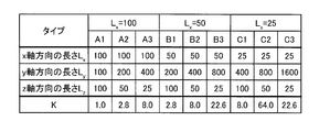
上記誘導装置において、前記磁化方向の長さは、前記第1の方向の長さの2/3以下であることを特徴とする。
In the induction device, the length in the magnetization direction is 2/3 or less of the length in the first direction.
上記誘導装置において、前記第2の永久磁石において前記磁化方向及び前記第1の方向と直交する第2の方向の長さは、前記第1の方向の長さよりも短いことを特徴とする。
In the induction device, the length of the second permanent magnet in the second direction perpendicular to the magnetization direction and the first direction is shorter than the length in the first direction.
上記誘導装置において、前記磁化方向の長さをLx、前記第1の方向の長さをLy、前記磁化方向及び前記第1の方向と直交する第2の方向の長さをLzとした場合に、

で与えられる値Kが1より大きく22.6以下であることを特徴とする。
In the induction device, the length in the magnetization direction is L x , the length in the first direction is L y , and the length in the second direction orthogonal to the magnetization direction and the first direction is L z . If
The value K given by is greater than 1 and less than or equal to 22.6.
上記誘導装置において、前記磁化方向の長さは、前記第2の方向の長さ以上であることを特徴とする。
In the induction device, the length in the magnetization direction is not less than the length in the second direction.
上記誘導装置は、前記第1の方向と平行な任意の基準面と直交する軸に対して前記第2の永久磁石を回転させる旋回角変更部をさらに備えることを特徴とする。
The guidance device further includes a turning angle changing unit that rotates the second permanent magnet with respect to an axis orthogonal to an arbitrary reference plane parallel to the first direction.
上記誘導装置は、前記第2の永久磁石を、前記第1の方向と平行な任意の基準面内において並進させる並進機構をさらに備えることを特徴とする。
The guide device further includes a translation mechanism that translates the second permanent magnet in an arbitrary reference plane parallel to the first direction.
上記誘導装置は、前記第1の方向と平行な軸を中心に前記第2の永久磁石を回転させることで、前記第1の方向と平行な任意の基準面に対する前記磁化方向の仰角を変化させる仰角変更部をさらに備えることを特徴とする。
The induction device changes an elevation angle of the magnetization direction with respect to an arbitrary reference plane parallel to the first direction by rotating the second permanent magnet around an axis parallel to the first direction. An elevation angle changing unit is further provided.
上記誘導装置において、前記基準面は水平面と平行であることを特徴とする。
In the above guidance device, the reference plane is parallel to a horizontal plane.
上記誘導装置は、前記第2の永久磁石により前記カプセル型医療装置の誘導が可能な磁界が生成される領域である有効磁界領域に対し、前記第2の永久磁石が生成する磁界を遮蔽する遮蔽手段であって、前記有効磁界領域に対して前記磁界が遮蔽されていない第1の状態と、前記有効磁界領域に対して前記磁界が遮蔽されている第2の状態とを切替可能な遮蔽手段をさらに備えることを特徴とする。
The guide device shields a magnetic field generated by the second permanent magnet from an effective magnetic field region in which a magnetic field that can be guided by the capsule medical device is generated by the second permanent magnet. A shielding means capable of switching between a first state in which the magnetic field is not shielded with respect to the effective magnetic field region and a second state in which the magnetic field is shielded with respect to the effective magnetic field region. Is further provided.
上記誘導装置において、前記遮蔽手段は、磁性体と、前記磁性体を前記第2の永久磁石と前記有効磁界領域との間に挿抜する駆動手段と、を有することを特徴とする。
In the induction device, the shielding means includes a magnetic body and a driving means for inserting and removing the magnetic body between the second permanent magnet and the effective magnetic field region.
上記誘導装置は、前記被検体を載置する載置台であって、前記被検体の検査対象である部位が載置される第1の領域と、前記被検体の検査対象ではない部位が載置される第2の領域とを含む載置台をさらに備え、前記磁性体は、前記載置台の前記第2の領域内に配置され、前記駆動手段は、前記載置台を介して前記磁性体を駆動することを特徴とする。
The guidance apparatus is a mounting table on which the subject is placed, and a first region on which a portion that is an examination target of the subject is placed, and a portion that is not the examination target of the subject is placed. The magnetic body is disposed in the second region of the mounting table, and the driving means drives the magnetic body via the mounting table. It is characterized by doing.
上記誘導装置において、前記遮蔽手段は、磁性流体と、前記第2の永久磁石と前記有効磁界領域との間に設けられ、前記磁性流体を収容可能な磁性流体収容部と、前記磁性流体収容部と連通する磁性流体貯蔵部と、前記磁性流体収容部と前記磁性流体貯蔵部との間で前記磁性流体を移動させる磁性流体移動手段と、を有することを特徴とする。
In the induction device, the shielding means is provided between the magnetic fluid, the second permanent magnet, and the effective magnetic field region, and can store the magnetic fluid, and the magnetic fluid storage A magnetic fluid storage unit communicating with the magnetic fluid storage unit; and a magnetic fluid moving unit configured to move the magnetic fluid between the magnetic fluid storage unit and the magnetic fluid storage unit.
上記誘導装置は、前記被検体を載置する載置台であって、前記被検体の検査対象である部位が載置される第1の領域と、前記被検体の検査対象ではない部位が載置される第2の領域とを含む載置台と、前記載置台を駆動して、前記載置台の位置を、前記第1の領域が前記第2の永久磁石と前記有効磁界領域との間に挿入された第1の位置と、前記第1の領域が前記第2の永久磁石と前記有効磁界領域との間から抜去された第2の位置とで切り替える駆動手段と、をさらに備え、前記遮蔽手段は、磁性流体と、前記載置台が前記第2の位置にあるときに、前記第2の永久磁石と前記有効磁界領域との間に挿入される領域に設けられ、前記磁性流体を収容可能な磁性流体収容部と、前記磁性流体収容部と連通する磁性流体貯蔵部と、前記駆動手段と連動して動作し、前記磁性流体収容部と前記磁性流体貯蔵部との間で前記磁性流体を移動させる磁性流体移動手段と、を有し、磁性流体移動手段は、前記載置台が前記第1の位置から前記第2の位置に遷移する際に、前記磁性流体を前記磁性流体収容部に移動させることを特徴とする。
The guidance apparatus is a mounting table on which the subject is placed, and a first region on which a portion that is an examination target of the subject is placed, and a portion that is not the examination target of the subject is placed. A mounting table including a second region to be driven, and the mounting table is driven to insert the position of the mounting table between the second permanent magnet and the effective magnetic field region. Drive means for switching between the first position and the second position where the first area is removed from between the second permanent magnet and the effective magnetic field area, and the shielding means Is provided in a region inserted between the second permanent magnet and the effective magnetic field region when the magnetic fluid and the mounting table are in the second position, and can accommodate the magnetic fluid. A magnetic fluid storage section; a magnetic fluid storage section communicating with the magnetic fluid storage section; And a magnetic fluid moving means for moving the magnetic fluid between the magnetic fluid storage part and the magnetic fluid storage part. The magnetic fluid is moved to the magnetic fluid container when the first position is changed to the second position.
上記誘導装置において、前記磁性流体移動手段は、前記磁性流体貯蔵部に設けられ、前記磁性流体貯蔵部内の体積を変化させることにより、前記磁性流体を前記磁性流体貯蔵部から前記磁性流体収容部に注入し、又は、前記磁性流体を前記磁性流体収容部から前記磁性流体貯蔵部に吸引するピストンであることを特徴とする。
In the induction device, the magnetic fluid moving means is provided in the magnetic fluid storage unit, and the magnetic fluid is transferred from the magnetic fluid storage unit to the magnetic fluid storage unit by changing a volume in the magnetic fluid storage unit. It is a piston that injects or sucks the magnetic fluid from the magnetic fluid storage part into the magnetic fluid storage part.
上記誘導装置は、前記遮蔽手段による前記磁界の遮蔽状態を検出する検出手段と、前記検出手段の検出結果と、前記カプセル型医療装置による検査のステータスとに応じて、前記第1の状態と前記第2の状態との切り替えを制御する制御手段と、をさらに備えることを特徴とする。
The guiding device includes: a detecting unit that detects a shielding state of the magnetic field by the shielding unit; a detection result of the detecting unit; and a status of an examination by the capsule medical device. And a control unit that controls switching between the second state and the second state.
上記誘導装置は、前記遮蔽手段による前記磁界の遮蔽状態を検出する検出手段と、前記検出手段による検出結果を報知する報知手段と、をさらに備えることを特徴とする。
The guidance device further includes detection means for detecting a shielding state of the magnetic field by the shielding means, and notification means for notifying a detection result by the detection means.
本発明によれば、第2の永久磁石の上記第1の方向の長さを上記第2の永久磁石の磁化方向の長さよりも長くするので、第2の永久磁石によってカプセル型医療装置の誘導に適した磁界を発生することが可能となる。この結果、カプセル型医療装置を効率良く誘導することができる誘導装置を実現することが可能となる。
According to the present invention, since the length of the second permanent magnet in the first direction is made longer than the length of the magnetization direction of the second permanent magnet, the capsule medical device is guided by the second permanent magnet. It is possible to generate a magnetic field suitable for the above. As a result, it is possible to realize a guiding device that can efficiently guide the capsule medical device.
以下に、本発明の実施の形態に係る誘導装置について、図面を参照しながら説明する。なお、以下の説明においては、カプセル型医療装置として、被検体内に経口にて導入され、被検体の胃に蓄えた液体中を漂うカプセル型内視鏡を用いるカプセル型内視鏡用誘導システムを例示するが、この実施の形態によって本発明が限定されるものではない。即ち、本発明は、例えば被検体の食道から肛門にかけて管腔内を移動するカプセル型内視鏡や、肛門から等張液とともに導入されるカプセル型内視鏡など、種々のカプセル型医療装置を用いることが可能である。また、以下の説明において、各図は本発明の内容を理解でき得る程度に形状、大きさ、及び位置関係を概略的に示してあるに過ぎない。従って、本発明は各図で例示された形状、大きさ、及び位置関係のみに限定されるものではない。なお、図面の記載において、同一部分には同一の符号を付している。
Hereinafter, a guidance device according to an embodiment of the present invention will be described with reference to the drawings. In the following description, a capsule endoscope guidance system using a capsule endoscope that is orally introduced into a subject and drifts in a liquid stored in the stomach of the subject as a capsule medical device. However, the present invention is not limited to this embodiment. That is, the present invention relates to various capsule medical devices such as a capsule endoscope that moves in the lumen from the esophagus of the subject to the anus and a capsule endoscope that is introduced from the anus together with an isotonic solution. It is possible to use. Moreover, in the following description, each figure has shown only the shape, magnitude | size, and positional relationship roughly so that the content of this invention can be understood. Therefore, the present invention is not limited only to the shape, size, and positional relationship illustrated in each drawing. In the description of the drawings, the same portions are denoted by the same reference numerals.
(実施の形態1)
図1は、本発明の実施の形態1に係るカプセル型医療装置誘導システムの一構成例を示す模式図である。図1に示すように、実施の形態1に係るカプセル型医療装置誘導システム(以下、単に誘導システムともいう)1は、被検体の体腔内に導入されるカプセル型医療装置であって、内部に永久磁石が設けられたカプセル型内視鏡10と、3次元的な磁界を発生して、被検体内に導入されたカプセル型内視鏡10を磁気誘導する誘導装置20とを備える。 (Embodiment 1)
FIG. 1 is a schematic diagram showing a configuration example of a capsule medical device guidance system according toEmbodiment 1 of the present invention. As shown in FIG. 1, a capsule medical device guidance system (hereinafter also simply referred to as a guidance system) 1 according to Embodiment 1 is a capsule medical device that is introduced into a body cavity of a subject. A capsule endoscope 10 provided with a permanent magnet and a guidance device 20 that generates a three-dimensional magnetic field and magnetically guides the capsule endoscope 10 introduced into the subject.
図1は、本発明の実施の形態1に係るカプセル型医療装置誘導システムの一構成例を示す模式図である。図1に示すように、実施の形態1に係るカプセル型医療装置誘導システム(以下、単に誘導システムともいう)1は、被検体の体腔内に導入されるカプセル型医療装置であって、内部に永久磁石が設けられたカプセル型内視鏡10と、3次元的な磁界を発生して、被検体内に導入されたカプセル型内視鏡10を磁気誘導する誘導装置20とを備える。 (Embodiment 1)
FIG. 1 is a schematic diagram showing a configuration example of a capsule medical device guidance system according to
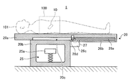
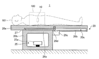
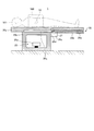
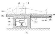
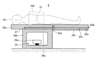
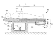
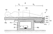
図2及び図3は、誘導装置20の一構成例を模式的に示す一部断面側面図である。図2は、カプセル型内視鏡10を誘導する磁界が遮蔽されていない状態(以下、磁界生成状態という)を示す。一方、図3は、カプセル型内視鏡10を誘導する磁界が遮蔽されている状態(以下、磁界遮蔽状態という)を示す。
2 and 3 are partial cross-sectional side views schematically showing a configuration example of the guidance device 20. FIG. 2 shows a state where the magnetic field for guiding the capsule endoscope 10 is not shielded (hereinafter referred to as a magnetic field generation state). On the other hand, FIG. 3 shows a state where a magnetic field for guiding the capsule endoscope 10 is shielded (hereinafter referred to as a magnetic field shielding state).
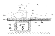
図2及び図3に示すように、誘導装置20には、被検体101が載置される載置台として、脚部20bに支持されたベッド20aが設けられている。以下において、カプセル型内視鏡10の誘導可能な磁界が生成される領域を有効磁界領域100という。実施の形態1において、有効磁界領域100はベッド20a上の一部の領域に設定されている。通常、被検体101は、この有効磁界領域100に検査(診断)対象部位が重なるように、ベッド20a上に載置される。
2 and 3, the guidance device 20 is provided with a bed 20a supported by a leg portion 20b as a mounting table on which the subject 101 is mounted. In the following, an area in which a magnetic field that can be guided by the capsule endoscope 10 is generated is referred to as an effective magnetic field area 100. In the first embodiment, the effective magnetic field region 100 is set in a partial region on the bed 20a. Usually, the subject 101 is placed on the bed 20a such that the examination (diagnosis) target region overlaps the effective magnetic field region 100.
カプセル型内視鏡10は、経口摂取等によって所定の液体とともに被検体101の臓器内部に導入された後、消化管内部を移動して、最終的に、被検体101の外部に排出される。カプセル型内視鏡10は、その間、被検体101の臓器内部(例えば胃内部)に導入された液体中を漂い、誘導装置20が生成した磁界によって磁気誘導されつつ被検体101内を順次撮像し、撮像によって取得した体内画像に対応する画像情報(画像データ)を順次無線送信する。なお、カプセル型内視鏡10の詳細な構造については後述する。
The capsule endoscope 10 is introduced into the organ of the subject 101 together with a predetermined liquid by ingestion or the like, then moves inside the digestive tract, and is finally discharged out of the subject 101. In the meantime, the capsule endoscope 10 drifts in the liquid introduced into the organ of the subject 101 (for example, the stomach), and sequentially images the subject 101 while being magnetically guided by the magnetic field generated by the guidance device 20. Then, image information (image data) corresponding to the in-vivo image acquired by imaging is sequentially wirelessly transmitted. The detailed structure of the capsule endoscope 10 will be described later.
誘導装置20は、カプセル型内視鏡10との間で無線通信を行いカプセル型内視鏡10が取得した画像情報を含む無線信号を受信する受信部21と、カプセル型内視鏡10から受信した無線信号に基づいて、被検体101内におけるカプセル型内視鏡10の位置を検出する位置検出部22と、受信部21が受信した無線信号から画像情報を取得し、該画像情報に所定の信号処理を施した体内画像や種々の情報を画面表示する表示部23aと、ユーザに対して視覚情報又は聴覚情報により報知を行う報知部23bと、誘導システム1における各種操作を指示する情報等の入力を受け付ける操作入力部24と、カプセル型内視鏡10を誘導するための磁界を生成する磁界生成部25と、磁界生成部25が生成する磁界を遮蔽する遮蔽部26と、遮蔽部26による磁界の遮蔽状態を検出する遮蔽状態検知部27と、これらの各部を制御する制御部28と、カプセル型内視鏡10によって撮像された画像情報などを記憶する記憶部29とを備える。
The guidance device 20 performs wireless communication with the capsule endoscope 10 and receives a wireless signal including image information acquired by the capsule endoscope 10 and receives from the capsule endoscope 10. Based on the radio signal, the position detection unit 22 for detecting the position of the capsule endoscope 10 in the subject 101 and the image information is acquired from the radio signal received by the reception unit 21, and the image information A display unit 23a that displays a signal-processed in-vivo image and various information on the screen, a notification unit 23b that notifies the user with visual information or auditory information, and information that instructs various operations in the guidance system 1 An operation input unit 24 that receives an input; a magnetic field generation unit 25 that generates a magnetic field for guiding the capsule endoscope 10; a shielding unit 26 that blocks a magnetic field generated by the magnetic field generation unit 25; A shielding state detection unit 27 that detects the shielding state of the magnetic field by the shielding unit 26, a control unit 28 that controls these units, and a storage unit 29 that stores image information captured by the capsule endoscope 10 and the like. Prepare.
受信部21は、複数のアンテナ21aを備え、これらの複数のアンテナ21aを介してカプセル型内視鏡10からの無線信号を順次受信する。受信部21は、複数のアンテナ21aの中から最も受信電界強度の高いアンテナを選択し、選択したアンテナを介して受信したカプセル型内視鏡10からの無線信号に対して復調処理等を行う。これにより、受信部21は、この無線信号から被検体101内に関する画像データを抽出する。受信部21は、抽出した画像データを含む画像信号を表示部23aに出力する。
The receiving unit 21 includes a plurality of antennas 21a, and sequentially receives radio signals from the capsule endoscope 10 via the plurality of antennas 21a. The receiving unit 21 selects the antenna having the highest received electric field strength from the plurality of antennas 21a, and performs a demodulation process or the like on the radio signal from the capsule endoscope 10 received via the selected antenna. Accordingly, the receiving unit 21 extracts image data related to the inside of the subject 101 from the wireless signal. The receiving unit 21 outputs an image signal including the extracted image data to the display unit 23a.
位置検出部22は、受信部21が受信した無線信号の信号強度に基づいて、被検体101内におけるカプセル型内視鏡10の位置を推定する演算を行う。
The position detection unit 22 performs a calculation for estimating the position of the capsule endoscope 10 in the subject 101 based on the signal strength of the radio signal received by the reception unit 21.
表示部23aは、液晶ディスプレイ等の各種ディスプレイを含み、受信部21から入力された画像データに基づく体内画像や、その他各種情報を含む画面を生成してディスプレイに表示する。具体的には、表示部23aは、例えば、カプセル型内視鏡10が撮像した被検体101の体内画像群を順次画面に表示すると共に、カプセル型内視鏡10の位置や姿勢に関する情報や誘導操作に関する情報を表示する。この際、表示部23aは、誘導装置20が発生する磁界から推定されるカプセル型内視鏡10の位置や姿勢を表示しても良いし、位置検出部22の位置検出結果に基づいて、表示中の体内画像に対応する被検体101内の位置を画面に表示しても良い。また、表示部23aは、例えば、制御部28の制御に従って選択された体内画像の縮小画像、被検体101の患者情報及び検査情報等を表示する。さらに、表示部23aは、制御部28の制御に従って、ユーザに対する警告や誘導装置20の状態(例えば磁界生成状態や磁界遮蔽状態)といった情報を画面に表示する。
The display unit 23a includes various displays such as a liquid crystal display, and generates and displays a screen including an in-vivo image based on the image data input from the receiving unit 21 and other various types of information. Specifically, for example, the display unit 23a sequentially displays in-vivo image groups of the subject 101 captured by the capsule endoscope 10 on a screen, and information and guidance regarding the position and orientation of the capsule endoscope 10. Display information about operations. At this time, the display unit 23a may display the position and posture of the capsule endoscope 10 estimated from the magnetic field generated by the guidance device 20, or display based on the position detection result of the position detection unit 22. A position in the subject 101 corresponding to the internal in-vivo image may be displayed on the screen. Further, the display unit 23a displays, for example, a reduced image of the in-vivo image selected under the control of the control unit 28, patient information and examination information of the subject 101, and the like. Furthermore, the display unit 23a displays information such as a warning for the user and the state of the guidance device 20 (for example, a magnetic field generation state and a magnetic field shielding state) on the screen according to the control of the control unit 28.
報知部23bは、例えば、LED等の照明デバイスやブザー等の音声デバイスと、これらのデバイスを制御するための、制御部28の制御の下で動作する駆動回路とを含む。報知部23bは、照明の点滅やブザー音等によりユーザに対する警告を報知し、或いは、所定の色の照明の点灯により誘導装置20の状態(例えば磁界生成状態や磁界遮蔽状態)をユーザに報知する。
The notification unit 23b includes, for example, an illumination device such as an LED and an audio device such as a buzzer, and a drive circuit that operates under the control of the control unit 28 for controlling these devices. The notification unit 23b notifies a user of a warning by lighting blinking, a buzzer sound, or the like, or notifies the user of the state of the guidance device 20 (for example, a magnetic field generation state or a magnetic field shielding state) by lighting a predetermined color lighting. .
操作入力部24は、ジョイスティック、各種ボタン及び各種スイッチを備えた操作卓、キーボード等の入力デバイスによって実現され、カプセル型内視鏡10を磁気で誘導するための誘導指示情報や誘導装置20に対して所定のモードを設定するための設定情報といった各種情報の入力を受け付ける。誘導指示情報は、磁気誘導操作対象であるカプセル型内視鏡10の位置や姿勢を制御するための情報であり、詳細には、カプセル型内視鏡10の位置を変化させる動作や、カプセル型内視鏡10の傾斜角(鉛直軸に対する角度)を変化させる動作に関する情報や、カプセル型内視鏡10の視野(後述する撮像部11A、11B)の方位角(鉛直軸周りの角度)を変化させる動作に関する情報等が含まれる。なお、以下において、視野の方位角のことを、単に方位角という。操作入力部24は、受け付けたこれらの情報を制御部28に入力する。
The operation input unit 24 is realized by an input device such as a joystick, a console with various buttons and various switches, a keyboard, and the like, and provides guidance information for guiding the capsule endoscope 10 magnetically and the guidance device 20. And receiving various information such as setting information for setting a predetermined mode. The guidance instruction information is information for controlling the position and posture of the capsule endoscope 10 that is the object of the magnetic guidance operation. Specifically, the guidance instruction information includes an operation for changing the position of the capsule endoscope 10 and a capsule type. Information related to the operation of changing the tilt angle (angle with respect to the vertical axis) of the endoscope 10 and the azimuth angle (angle around the vertical axis) of the visual field ( imaging units 11A and 11B described later) of the capsule endoscope 10 are changed. Information on the operation to be performed is included. In the following, the azimuth angle of the visual field is simply referred to as azimuth angle. The operation input unit 24 inputs the received information to the control unit 28.
磁界生成部25は、ベッド20aの下部(脚部20bの内側)に設けられ、被検体101内に導入されたカプセル型内視鏡10の位置や傾斜角や方位角を被検体101に対して相対的に変化させるための磁界を、有効磁界領域100に生成する。なお、磁界生成部25が生成する磁界の有効磁界領域100以外(例えば、脚部20bの側面方向)の空間への漏れを抑制するため、脚部20bを鉄板等の強磁性体によって形成することが好ましい。
The magnetic field generation unit 25 is provided below the bed 20 a (inside the leg portion 20 b), and determines the position, inclination angle, and azimuth angle of the capsule endoscope 10 introduced into the subject 101 with respect to the subject 101. A magnetic field for relatively changing is generated in the effective magnetic field region 100. In addition, in order to suppress the leakage of the magnetic field generated by the magnetic field generation unit 25 to a space other than the effective magnetic field region 100 (for example, the side surface direction of the leg 20b), the leg 20b is formed of a ferromagnetic material such as an iron plate. Is preferred.
磁界生成部25は、磁界を発生する体外永久磁石25aと、該体外永久磁石25aを並進及び回転させる機構として、平面位置変更部25bと、鉛直位置変更部25cと、仰角変更部25dと、旋回角変更部25eとを有する。
The magnetic field generation unit 25 includes an extracorporeal permanent magnet 25a that generates a magnetic field, a plane position changing unit 25b, a vertical position changing unit 25c, an elevation angle changing unit 25d, and a swiveling mechanism that translates and rotates the extracorporeal permanent magnet 25a. And a corner changing unit 25e.
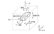
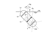
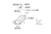
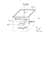
図4は、体外永久磁石25aの設置状態を説明するための模式図である。図4に示すように、体外永久磁石25aは、例えば直方体形状を有する棒磁石によって実現される。体外永久磁石25aは、磁化方向及び該磁化方向と直交する第1の方向を含む面と対向する領域内にカプセル型内視鏡10を拘束する。以下、体外永久磁石25aのうち、カプセル型内視鏡10と対向する面のことを、カプセル対向面PL1(第1の面)という。
FIG. 4 is a schematic diagram for explaining an installation state of the extracorporeal permanent magnet 25a. As shown in FIG. 4, the extracorporeal permanent magnet 25a is realized by, for example, a bar magnet having a rectangular parallelepiped shape. The extracorporeal permanent magnet 25a restrains the capsule endoscope 10 in a region facing a magnetization direction and a surface including a first direction orthogonal to the magnetization direction. Hereinafter, the surface of the extracorporeal permanent magnet 25a that faces the capsule endoscope 10 is referred to as a capsule facing surface PL1 (first surface).
体外永久磁石25aは、上記第1の方向(図4においてはY軸方向)と平行な任意の面を基準として配置される。本実施の形態1において、当該基準面は水平面と平行に設定され、カプセル型内視鏡10の初期状態において、カプセル対向面PL1は基準面(水平面)と平行になるように配置される。以下、体外永久磁石25aがカプセル型内視鏡10の初期状態にあるときの体外永久磁石25aの配置を初期位置とし、このときの磁化方向をX軸方向、磁化方向と直交する水平面内の方向をY軸方向、鉛直方向をZ軸方向とする。
The extracorporeal permanent magnet 25a is arranged with reference to an arbitrary plane parallel to the first direction (Y-axis direction in FIG. 4). In the first embodiment, the reference plane is set parallel to the horizontal plane, and in the initial state of the capsule endoscope 10, the capsule facing surface PL1 is arranged to be parallel to the reference plane (horizontal plane). Hereinafter, the arrangement of the extracorporeal permanent magnet 25a when the extracorporeal permanent magnet 25a is in the initial state of the capsule endoscope 10 is set as the initial position, and the magnetization direction at this time is the X axis direction and the direction in the horizontal plane perpendicular to the magnetization direction. Is the Y-axis direction, and the vertical direction is the Z-axis direction.
体外永久磁石25aは、直方体形状の3方向の辺の長さの内、カプセル対向面PL1内で磁化方向と直交する方向(図4においては、Y軸方向)の辺の長さが、磁化方向(図4においては、X軸方向)及びカプセル対向面PL1と直交する方向(図4においては、Z軸方向)よりも長い形状を有している。好ましくは、体外永久磁石25aは、直方体形状の3方向の辺の長さの内、カプセル対向面PL1と直交する方向の長さが最も短い平板形状を有している。なお、体外永久磁石25aの形状については、後で詳述する。
The extracorporeal permanent magnet 25a has a length in the direction perpendicular to the magnetization direction (the Y-axis direction in FIG. 4) in the capsule facing surface PL1 among the lengths of the three directions of the rectangular parallelepiped shape. (In FIG. 4, the X-axis direction) and a direction longer than the capsule facing surface PL1 (the Z-axis direction in FIG. 4) are longer. Preferably, extracorporeal permanent magnet 25a has a flat plate shape with the shortest length in the direction orthogonal to capsule facing surface PL1 among the lengths of the three sides of the rectangular parallelepiped shape. The shape of the extracorporeal permanent magnet 25a will be described in detail later.
平面位置変更部25bは、体外永久磁石25aを、基準面として設定された水平面内において並進させる並進機構である。即ち、体外永久磁石25aにおいて磁化された2つの磁極の相対位置が確保された状態のままで水平面内に移動を行うものである。
The plane position changing unit 25b is a translation mechanism that translates the extracorporeal permanent magnet 25a in a horizontal plane set as a reference plane. That is, the movement is performed in the horizontal plane while the relative position of the two magnetic poles magnetized in the extracorporeal permanent magnet 25a is secured.
鉛直位置変更部25cは、体外永久磁石25aを、基準面として設定された水平面と直交する鉛直方向において並進させる並進機構である。
The vertical position changing unit 25c is a translation mechanism that translates the extracorporeal permanent magnet 25a in a vertical direction orthogonal to a horizontal plane set as a reference plane.
仰角変更部25dは、カプセル対向面PL1と平行且つ磁化方向と直交し、体外永久磁石25aの中心を通る軸(以下、回転軸YCという)に対して体外永久磁石25aを回転させることにより、基準面として設定された水平面に対する磁化方向の角度を変化させる回転機構である。以下、体外永久磁石25aと水平面とのなす角度を仰角θとする。
The elevation angle changing unit 25d rotates the extracorporeal permanent magnet 25a with respect to an axis that is parallel to the capsule facing surface PL1 and orthogonal to the magnetization direction and passes through the center of the extracorporeal permanent magnet 25a (hereinafter referred to as a rotation axis Y C ). It is a rotation mechanism that changes the angle of the magnetization direction with respect to a horizontal plane set as a reference plane. Hereinafter, the angle between the extracorporeal permanent magnet 25a and the horizontal plane is defined as an elevation angle θ.
旋回角変更部25eは、基準面と直交する軸に対して体外永久磁石25aを回転させる。本実施の形態1においては、体外永久磁石25aの中心を通る鉛直方向の軸を、体外永久磁石25aの回転軸とする。以下、体外永久磁石25aの鉛直方向の軸に対する回転運動を旋回運動という。また、初期位置に対して体外永久磁石25aが旋回した角度を旋回角ψとする。
The turning angle changing unit 25e rotates the extracorporeal permanent magnet 25a with respect to an axis orthogonal to the reference plane. In the first embodiment, the axis in the vertical direction passing through the center of the extracorporeal permanent magnet 25a is used as the rotation axis of the extracorporeal permanent magnet 25a. Hereinafter, the rotational movement of the extracorporeal permanent magnet 25a with respect to the vertical axis is referred to as a turning movement. In addition, an angle at which the extracorporeal permanent magnet 25a turns with respect to the initial position is set as a turning angle ψ.
旋回角変更部25eにより体外永久磁石25aを旋回角ψだけ旋回させ、初期位置に対する回転軸YCの角度を変化させた状態で、仰角変更部25dにより体外永久磁石25aを回転軸YCに対して回転させることで、体外永久磁石25aが発生する磁界に拘束されたカプセル型内視鏡10の方位角及び傾斜角を変化させることができる。
By turning angle changing unit 25e to pivot the extracorporeal permanent magnet 25a only turn angle [psi, in a state of changing the angle of the rotation axis Y C to the initial position, with respect to the rotation axis Y C extracorporeal permanent magnet 25a by elevation changing unit 25d The azimuth angle and tilt angle of the capsule endoscope 10 constrained by the magnetic field generated by the extracorporeal permanent magnet 25a can be changed.
図2及び図3に示すように、遮蔽部26は、ベッド20aの下面に設けられた板状の磁性体部材26aと、該磁性体部材26aをベッド20aの下面においてベッド20aの主面に対してスライド可能に支持する支持部26bと、磁性体部材26aをベッド20aに沿って駆動する駆動部26cと、固定部26dとを有する。
As shown in FIG. 2 and FIG. 3, the shielding part 26 includes a plate-like magnetic member 26a provided on the lower surface of the bed 20a, and the magnetic member 26a on the lower surface of the bed 20a with respect to the main surface of the bed 20a. And a support portion 26b that is slidably supported, a drive portion 26c that drives the magnetic member 26a along the bed 20a, and a fixing portion 26d.
ここで、体外永久磁石25aは、電磁石と異なり、磁界発生のオン/オフや磁界の強度調整等を行うことができない。即ち、永久磁石は常時、所定の強度を有する磁界を発生するため、カプセル型内視鏡10の誘導操作を行っていないときや、誘導装置20を使用していないときに、カプセル型内視鏡10の意図しない移動や、被検体101への影響を抑制するために、磁界の強度を弱くするか、好ましくは遮蔽する必要がある。この点について、誘導装置20の非使用時には、強磁性体で生成された覆い部を体外永久磁石25aに被せて遮蔽するといった構成も考えられるが、この場合、磁界を遮蔽するための操作が煩雑であり、例えば、緊急事態が発生した時に素早く対応することが困難である。
Here, unlike the electromagnet, the extracorporeal permanent magnet 25a cannot perform magnetic field generation on / off, magnetic field intensity adjustment, or the like. That is, since the permanent magnet always generates a magnetic field having a predetermined strength, the capsule endoscope is not used when the capsule endoscope 10 is not guided or when the guide device 20 is not used. In order to suppress 10 unintended movements and the influence on the subject 101, it is necessary to weaken or preferably shield the magnetic field. With respect to this point, when the guidance device 20 is not used, a configuration in which the cover part generated by the ferromagnetic material is covered with the extracorporeal permanent magnet 25a and shielded is conceivable. However, in this case, the operation for shielding the magnetic field is complicated. For example, it is difficult to respond quickly when an emergency occurs.
それに対して、本実施の形態1においては、誘導装置20に遮蔽部26を設けることにより、より簡単な操作で有効磁界領域100における磁界を遮蔽することができる構成を提供するものである。
On the other hand, the first embodiment provides a configuration in which the magnetic field in the effective magnetic field region 100 can be shielded by a simpler operation by providing the guiding device 20 with the shielding part 26.
磁性体部材26aは、好ましくは強磁性体によって形成され、ベッド20aの下に挿入されることにより、磁界生成部25が生成する磁界を有効磁界領域100に対して遮蔽する。磁性体部材26aは、磁界生成部25が生成する磁界を有効磁界領域100に対して遮蔽できる素材及びサイズ(幅×長さ×厚さ)を有していれば良い。なお、本明細書において、幅とは、被検体101の横幅方向における寸法のことをいい、長さとは、被検体101の身長方向における寸法のことをいう。実施の形態1において、磁性体部材26aとして、例えばベッド20aの幅とほぼ等しい幅×ベッド20aの長さの半分程度の長さに形成した部材を用いている。
The magnetic member 26a is preferably formed of a ferromagnetic material, and is inserted under the bed 20a to shield the magnetic field generated by the magnetic field generating unit 25 from the effective magnetic field region 100. The magnetic body member 26a only needs to have a material and a size (width × length × thickness) that can shield the magnetic field generated by the magnetic field generation unit 25 from the effective magnetic field region 100. In this specification, the width refers to the dimension in the width direction of the subject 101, and the length refers to the dimension in the height direction of the subject 101. In the first embodiment, as the magnetic member 26a, for example, a member formed to have a width approximately equal to the width of the bed 20a × about half the length of the bed 20a is used.
ベッド20aの下面には、磁性体部材26aが配置される凹部20cが設けられている。この凹部20cは、有効磁界領域100、即ち、被検体101の検査対象部位(例えば、胃部)が乗せられる領域から、検査対象ではない部位(例えば、下肢)が乗せられる領域までに対応するようその位置が決定されている。磁性体部材26aは、この凹部20cにおいて、ベッド20aの長さ方向にスライドして移動する。
A recess 20c in which the magnetic member 26a is disposed is provided on the lower surface of the bed 20a. The recess 20c corresponds to the effective magnetic field region 100, that is, from the region where the examination target portion (for example, the stomach) of the subject 101 is placed to the region where the portion (for example, the lower limb) that is not the examination target is placed. Its position has been determined. The magnetic member 26a slides and moves in the length direction of the bed 20a in the recess 20c.
支持部26bは、凹部20cに配置された磁性体部材26aを下側から支持する。好ましくは、磁性体部材26aをスライドさせ易くするため、支持部26bの上面(磁性体部材26aとの接触面)に、レール及び滑車を設けても良い。
The support portion 26b supports the magnetic body member 26a disposed in the recess 20c from below. Preferably, in order to facilitate the sliding of the magnetic member 26a, a rail and a pulley may be provided on the upper surface of the support portion 26b (contact surface with the magnetic member 26a).
駆動部26cは、凹部20c内で磁性体部材26aをベッド20aの長さ方向に移動させて、磁界生成部25と有効磁界領域100との間に対して磁性体部材26aを挿抜する。磁性体部材26aが磁界生成部25と有効磁界領域100との間に挿入されることにより、誘導装置20は磁界遮蔽状態となる(図3参照)。一方、磁性体部材26aが磁界生成部25と有効磁界領域100との間から抜去されることにより、誘導装置20は磁界生成状態となる(図2参照)。
The driving unit 26c moves the magnetic member 26a in the length direction of the bed 20a in the recess 20c, and inserts and removes the magnetic member 26a between the magnetic field generating unit 25 and the effective magnetic field region 100. When the magnetic member 26a is inserted between the magnetic field generator 25 and the effective magnetic field region 100, the guidance device 20 is in a magnetic field shielding state (see FIG. 3). On the other hand, when the magnetic member 26a is removed from between the magnetic field generation unit 25 and the effective magnetic field region 100, the guidance device 20 enters a magnetic field generation state (see FIG. 2).
固定部26dは、凹部20cの中間付近に設けられており、磁界生成状態と磁界遮蔽状態との間で意図しない遷移が生じないように、磁性体部材26aの位置を固定している。特に、誘導装置20が磁界生成状態にあるとき(図2参照)、磁性体部材26aには磁界生成部25が生成する磁界から、磁界遮蔽状態における位置にスライドさせようとする磁気引力が働く。このため、固定部26dにより、磁性体部材26aの移動を機械的に妨げている。なお、磁界生成状態から磁界遮蔽状態に遷移する際には、固定部26dは、制御部28の制御の下で動作する駆動部(図示せず)により、図の上方に移動させられる。それにより、磁性体部材26aの固定状態が解除される(図3参照)。なお、固定部26dを手動で操作して、磁性体部材26aの固定状態を解除しても良い。
The fixing portion 26d is provided near the middle of the recess 20c, and fixes the position of the magnetic member 26a so that an unintended transition between the magnetic field generation state and the magnetic field shielding state does not occur. In particular, when the guidance device 20 is in a magnetic field generation state (see FIG. 2), a magnetic attractive force that attempts to slide the magnetic member 26a from the magnetic field generated by the magnetic field generation unit 25 to a position in the magnetic field shielding state acts. For this reason, the movement of the magnetic member 26a is mechanically hindered by the fixing portion 26d. When the magnetic field generation state transitions to the magnetic field shielding state, the fixing unit 26d is moved upward in the drawing by a driving unit (not shown) that operates under the control of the control unit 28. Thereby, the fixed state of the magnetic member 26a is released (see FIG. 3). Note that the fixed portion 26d may be manually operated to release the fixed state of the magnetic member 26a.
遮蔽状態検知部27は、例えば、磁性体部材26aに印加される水平方向の圧力を検知する圧力センサによって実現される。ここで、上述したように、誘導装置20が磁界生成状態にあるとき(図2参照)、体外永久磁石25aと磁性体部材26aとの間には磁気引力が働く。従って、このとき、磁性体部材26aには、水平方向においては図の左方向の圧力が印加されている。一方、誘導装置20が磁界遮蔽状態にあるとき(図3参照)、体外永久磁石25aと磁性体部材26aとの間の磁気引力は主に上下方向に働くため、磁性体部材26aには水平方向の圧力はほとんどかからない。そこで、遮蔽状態検知部27で磁性体部材26aに印加される水平方向における圧力を検出することにより、誘導装置20の状態を判断することができる。即ち、遮蔽状態検知部27の出力値が所定の閾値以上である場合には、誘導装置20が磁界生成状態にあると判断することができる。反対に、この出力値が所定の閾値よりも小さい場合には、誘導装置20が磁界遮蔽状態にあると判断することができる。なお、この判断は、遮蔽状態検知部27の出力結果に基づいて制御部28が行う。
The shielding state detection unit 27 is realized by, for example, a pressure sensor that detects a horizontal pressure applied to the magnetic member 26a. Here, as described above, when the guidance device 20 is in a magnetic field generating state (see FIG. 2), a magnetic attractive force acts between the extracorporeal permanent magnet 25a and the magnetic member 26a. Accordingly, at this time, a pressure in the left direction in the figure is applied to the magnetic member 26a in the horizontal direction. On the other hand, when the guidance device 20 is in the magnetic field shielding state (see FIG. 3), the magnetic attractive force between the extracorporeal permanent magnet 25a and the magnetic member 26a mainly works in the vertical direction, so that the magnetic member 26a has a horizontal direction. Little pressure is applied. Therefore, the state of the guiding device 20 can be determined by detecting the horizontal pressure applied to the magnetic member 26a by the shielding state detection unit 27. That is, when the output value of the shielding state detection unit 27 is equal to or greater than a predetermined threshold, it can be determined that the guidance device 20 is in the magnetic field generation state. On the contrary, when the output value is smaller than a predetermined threshold value, it can be determined that the guidance device 20 is in the magnetic field shielding state. This determination is made by the control unit 28 based on the output result of the shielding state detection unit 27.
また、遮蔽状態検知部27としては、圧力センサの他にも、圧縮センサ、ひずみセンサ、加速度センサ(力センサ)のように、磁性体部材26aに印加される所定の方向における力の大きさを検出できるものであれば、どのようなセンサを用いても良い。或いは、磁性体部材26aの代わりに、体外永久磁石25aに印加される力を検知することにより、誘導装置20の状態を判断するようにしても良い。
In addition to the pressure sensor, the shielding state detection unit 27 is a force sensor in a predetermined direction applied to the magnetic member 26a, such as a compression sensor, a strain sensor, and an acceleration sensor (force sensor). Any sensor may be used as long as it can be detected. Or you may make it judge the state of the guidance apparatus 20 by detecting the force applied to the external permanent magnet 25a instead of the magnetic body member 26a.
制御部28は、位置検出部22の検出結果、及び操作入力部24から入力された誘導指示情報に基づいて磁界生成部25の各部の動作を制御することにより、カプセル型内視鏡10のユーザ所望の位置、傾斜角、及び方位角を実現する。また、制御部28は、操作入力部24から入力された操作信号に従って遮蔽部26を制御し、誘導装置20をカプセル型内視鏡検査のステータスに応じた状態(磁界生成状態又は磁界遮蔽状態)に遷移させる。
The control unit 28 controls the operation of each unit of the magnetic field generation unit 25 based on the detection result of the position detection unit 22 and the guidance instruction information input from the operation input unit 24, so that the user of the capsule endoscope 10 Realize desired position, tilt angle, and azimuth. Further, the control unit 28 controls the shielding unit 26 in accordance with the operation signal input from the operation input unit 24, and the guidance device 20 is in a state (magnetic field generation state or magnetic field shielding state) according to the status of the capsule endoscopy. Transition to.
記憶部29は、フラッシュメモリ又はハードディスク等の書き換え可能に情報を保存する記憶メディアを用いて実現される。記憶部29は、カプセル型内視鏡10によって撮像された被検体101の体内画像群の画像データの他、制御部28が誘導装置20の各部を制御するための各種プログラムや各種パラメータといった情報を記憶する。
The storage unit 29 is realized using a storage medium that stores information in a rewritable manner such as a flash memory or a hard disk. In addition to the image data of the in-vivo image group of the subject 101 captured by the capsule endoscope 10, the storage unit 29 stores information such as various programs and various parameters for the control unit 28 to control each unit of the guidance device 20. Remember.
次に、カプセル型内視鏡10の詳細な構造について説明する。図5は、カプセル型内視鏡10の内部構造の一例を示す断面模式図である。図5に示すように、カプセル型内視鏡10は、被検体101の臓器内部に導入し易い大きさに形成された外装であるカプセル型筐体12と、互いに異なる撮像方向の被写体を撮像して画像情報を生成する撮像部11A、11Bとを備える。また、カプセル型内視鏡10は、撮像部11A、11Bによって取得された画像情報を外部に無線送信する無線通信部16と、カプセル型内視鏡10の各構成部を制御する制御部17と、カプセル型内視鏡10の各構成部に電力を供給する電源部18とを備える。さらに、カプセル型内視鏡10は、誘導装置20による磁気誘導を可能にするための永久磁石19を備える。
Next, the detailed structure of the capsule endoscope 10 will be described. FIG. 5 is a schematic cross-sectional view showing an example of the internal structure of the capsule endoscope 10. As shown in FIG. 5, the capsule endoscope 10 images subjects in different imaging directions from the capsule-type casing 12 that is an exterior formed in a size that can be easily introduced into the organ of the subject 101. Imaging units 11A and 11B that generate image information. The capsule endoscope 10 includes a wireless communication unit 16 that wirelessly transmits image information acquired by the imaging units 11A and 11B to the outside, and a control unit 17 that controls each component of the capsule endoscope 10. And a power supply unit 18 that supplies power to each component of the capsule endoscope 10. Furthermore, the capsule endoscope 10 includes a permanent magnet 19 for enabling magnetic guidance by the guidance device 20.
カプセル型筐体12は、被検体101の臓器内部に導入可能な大きさに形成された外装ケースであり、筒状筐体12aの両側開口端をドーム形状筐体12b、12cによって塞ぐことによって実現される。ドーム形状筐体12b、12cは、可視光等の所定波長帯域の光に対して透明なドーム形状の光学部材である。また、筒状筐体12aは、可視光に対して略不透明な有色の筐体である。これらの筒状筐体12a及びドーム形状筐体12b、12cによって形成されるカプセル型筐体12は、図5に示すように、撮像部11A、11B、無線通信部16、制御部17、電源部18及び永久磁石19を液密に内包する。
The capsule-type housing 12 is an outer case formed to have a size that can be introduced into the organ of the subject 101, and is realized by closing both side opening ends of the cylindrical housing 12a with dome-shaped housings 12b and 12c. Is done. The dome-shaped casings 12b and 12c are dome-shaped optical members that are transparent to light of a predetermined wavelength band such as visible light. The cylindrical housing 12a is a colored housing that is substantially opaque to visible light. As shown in FIG. 5, the capsule housing 12 formed by the cylindrical housing 12a and the dome-shaped housings 12b and 12c includes an imaging unit 11A, 11B, a wireless communication unit 16, a control unit 17, and a power supply unit. 18 and the permanent magnet 19 are enclosed in a liquid-tight manner.
撮像部11Aは、LED等の照明部13Aと、集光レンズ等の光学系14Aと、CMOSイメージセンサ又はCCD等の撮像素子15Aとを有する。照明部13Aは、撮像素子15Aの撮像視野に白色光等の照明光を発光して、ドーム形状筐体12b越しに撮像視野内の被写体を照明する。光学系14Aは、この撮像視野からの反射光を撮像素子15Aの撮像面に集光し、撮像視野の被写体像を結像する。撮像素子15Aは、撮像面に集光された撮像視野からの反射光を受光し、受光した光信号を光電変換処理して、撮像視野の被写体像、即ち被検体101の体内画像を表す画像情報を生成する。
The imaging unit 11A includes an illumination unit 13A such as an LED, an optical system 14A such as a condenser lens, and an imaging element 15A such as a CMOS image sensor or a CCD. The illuminating unit 13A emits illumination light such as white light to the imaging field of the image sensor 15A, and illuminates the subject in the imaging field through the dome-shaped housing 12b. The optical system 14A condenses the reflected light from the imaging field of view on the imaging surface of the imaging element 15A to form a subject image in the imaging field of view. The image sensor 15A receives reflected light from the imaging field focused on the imaging surface, performs photoelectric conversion processing on the received optical signal, and represents image information representing the subject image in the imaging field, that is, the in-vivo image of the subject 101. Is generated.
撮像部11Bは、撮像部11Aと同様に、LED等の照明部13Bと、集光レンズ等の光学系14Bと、CMOSイメージセンサ又はCCD等の撮像素子15Bとを有する。
Similarly to the imaging unit 11A, the imaging unit 11B includes an illumination unit 13B such as an LED, an optical system 14B such as a condenser lens, and an imaging element 15B such as a CMOS image sensor or a CCD.
図5に示すように、カプセル型内視鏡10が長軸La方向の前方及び後方を撮像する2眼タイプのカプセル型医療装置である場合、これらの撮像部11A、11Bは、各光軸がカプセル型筐体12の長手方向の中心軸である長軸Laと略平行又は略一致し、且つ各撮像視野が互いに反対方向を向くように配置される。即ち、撮像素子15A、15Bの撮像面が長軸Laに対して直交するように、撮像部11A、11Bが実装される。
As shown in FIG. 5, when the capsule endoscope 10 is a binocular capsule medical device that images the front and rear in the direction of the long axis La, the imaging units 11 </ b> A and 11 </ b> B each have an optical axis. The capsule housing 12 is arranged so as to be substantially parallel or substantially coincident with the long axis La, which is the central axis in the longitudinal direction of the capsule housing 12, and the imaging fields of view are directed in opposite directions. That is, the imaging units 11A and 11B are mounted so that the imaging surfaces of the imaging elements 15A and 15B are orthogonal to the long axis La.
無線通信部16は、アンテナ16aを備え、上述した撮像部11A、11Bによって取得された画像情報を、アンテナ16aを介して外部に順次無線送信する。具体的には、無線通信部16は、撮像部11A又は撮像部11Bが生成した画像情報に基づく画像信号を制御部17から取得し、該画像信号に対して変調処理等を行って、この画像信号を変調した無線信号を生成する。無線通信部16は、この無線信号を、アンテナ16aを介して外部の受信部21に送信する。
The wireless communication unit 16 includes an antenna 16a, and sequentially wirelessly transmits the image information acquired by the imaging units 11A and 11B described above to the outside via the antenna 16a. Specifically, the wireless communication unit 16 acquires an image signal based on the image information generated by the imaging unit 11A or the imaging unit 11B from the control unit 17, performs a modulation process on the image signal, and performs this image processing. A radio signal obtained by modulating the signal is generated. The wireless communication unit 16 transmits this wireless signal to the external receiving unit 21 via the antenna 16a.
制御部17は、撮像部11A、11B及び無線通信部16の各動作を制御すると共に、これらの各構成部間における信号の入出力を制御する。具体的には、制御部17は、照明部13Aが照明した撮像視野内の被写体を撮像素子15Aに撮像させ、照明部13Bが照明した撮像視野内の被写体を撮像素子15Bに撮像させる。また、制御部17は、画像信号を生成する信号処理機能を有する。制御部17は、撮像素子15A、15Bから画像情報を取得し、その都度、この画像情報に対して所定の信号処理を施して、画像データを含む画像信号を生成する。さらに、制御部17は、このような画像信号を時系列に沿って外部に順次無線送信するように無線通信部16を制御する。
The control unit 17 controls each operation of the imaging units 11A and 11B and the wireless communication unit 16, and controls input / output of signals between these components. Specifically, the control unit 17 causes the imaging device 15A to image the subject in the imaging field illuminated by the illumination unit 13A, and causes the imaging device 15B to image the subject in the imaging field illuminated by the illumination unit 13B. The control unit 17 has a signal processing function for generating an image signal. The control unit 17 acquires image information from the image sensors 15A and 15B, and performs predetermined signal processing on the image information each time to generate an image signal including image data. Further, the control unit 17 controls the wireless communication unit 16 so as to sequentially wirelessly transmit such image signals to the outside along a time series.
電源部18は、ボタン型電池又はキャパシタ等の蓄電部であって、磁気スイッチや光スイッチ等のスイッチ部を有する。電源部18は、外部から印加された磁界によって電源のオンオフ状態を切り替え、オン状態の場合に、蓄電部の電力をカプセル型内視鏡10の各構成部(撮像部11A、11B、無線通信部16、及び制御部17)に適宜供給する。また、電源部18は、オフ状態の場合に、カプセル型内視鏡10の各構成部への電力供給を停止する。
The power supply unit 18 is a power storage unit such as a button-type battery or a capacitor, and has a switch unit such as a magnetic switch or an optical switch. The power supply unit 18 switches the on / off state of the power supply by a magnetic field applied from the outside. When the power supply unit 18 is in the on state, the power of the power storage unit is transferred to each component of the capsule endoscope 10 ( imaging units 11A and 11B, wireless communication unit 16 and the control unit 17). Further, the power supply unit 18 stops the power supply to each component of the capsule endoscope 10 when it is in the off state.
永久磁石19は、磁界生成部25が生成した磁界により、有効磁界領域100におけるカプセル型内視鏡10の磁気誘導を可能にするためのものであり、磁化方向が長軸Laに対して傾きを持つように、カプセル型筐体12の内部に固定配置される。具体的には、永久磁石19は、磁化方向が長軸Laに対して直交するように配置される。永久磁石19は、外部から印加された磁界に追従して動作し、この結果、磁界生成部25によるカプセル型内視鏡10の磁気誘導が実現する。
The permanent magnet 19 is for enabling magnetic guidance of the capsule endoscope 10 in the effective magnetic field region 100 by the magnetic field generated by the magnetic field generator 25, and the magnetization direction is inclined with respect to the long axis La. It is fixedly arranged inside the capsule-type housing 12 so as to have it. Specifically, the permanent magnet 19 is arranged so that the magnetization direction is orthogonal to the long axis La. The permanent magnet 19 operates following a magnetic field applied from the outside. As a result, the magnetic guidance of the capsule endoscope 10 by the magnetic field generation unit 25 is realized.
ここで、図6を参照しながら、撮像素子15A、15Bと永久磁石19との相対的な位置関係について説明する。永久磁石19は、上述した撮像部11A、11Bに対して相対的に固定された状態でカプセル型筐体12の内部に固定配置される。より詳細には、永久磁石19は、その磁化方向が、撮像素子15A、15Bの各撮像面の上下方向に対して相対的に固定されるように配置される。具体的には、図6に示すように、永久磁石19は、その磁化方向Ymが撮像素子15A、15Bの各撮像面の上下方向Yuに対して平行となるように配置される。
Here, the relative positional relationship between the imaging elements 15A and 15B and the permanent magnet 19 will be described with reference to FIG. The permanent magnet 19 is fixedly arranged inside the capsule casing 12 in a state of being fixed relatively to the above-described imaging units 11A and 11B. More specifically, the permanent magnet 19 is arranged such that its magnetization direction is fixed relative to the vertical direction of the imaging surfaces of the imaging elements 15A and 15B. Specifically, as shown in FIG. 6, the permanent magnet 19 is arranged so that the magnetization direction Ym thereof is parallel to the vertical direction Yu of the imaging surfaces of the imaging elements 15A and 15B.
図7は、被検体101内に液体Wを導入した状態でのカプセル型内視鏡10の様子を説明するための概念図である。なお、図7は、カプセル型内視鏡10の位置、傾斜角、及び方位角を制御するための磁界が永久磁石19に作用していない状態を示している。
FIG. 7 is a conceptual diagram for explaining the state of the capsule endoscope 10 with the liquid W introduced into the subject 101. FIG. 7 shows a state where a magnetic field for controlling the position, tilt angle, and azimuth angle of the capsule endoscope 10 is not acting on the permanent magnet 19.
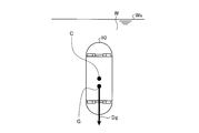
実施の形態1において例示するカプセル型内視鏡10は、液体Wに対する比重がほぼ1となるように設計されている。また、カプセル型内視鏡10の重心Gは、カプセル型内視鏡10の幾何学的中心Cからカプセル型内視鏡10の長軸La(カプセル型内視鏡10の長手方向の中心軸:図5参照)に沿ってずれた位置となるように設定されている。具体的には、カプセル型内視鏡10の重心Gは、電源部18及び永久磁石19等の各構成部の配置を調整することにより、長軸La上の位置であってカプセル型筐体12の幾何学的中心Cから撮像部11B側に外れた位置に設定される。これにより、カプセル型内視鏡10は、自身の長軸Laが鉛直方向(即ち、重力方向)と略平行になった状態で、液体W中を漂う。言い換えると、カプセル型内視鏡10は、幾何学的中心Cと重心Gとを結ぶ直線が直立した状態で液体W中を漂う。カプセル型内視鏡10は、このような直立姿勢において、鉛直上方に撮像部11Aの撮像視野を向けるとともに鉛直下方に撮像部11Bの撮像視野を向ける。なお、液体Wは、水又は生理食塩水等の人体に無害な液体である。
The capsule endoscope 10 illustrated in the first embodiment is designed so that the specific gravity with respect to the liquid W is approximately 1. The center of gravity G of the capsule endoscope 10 is from the geometric center C of the capsule endoscope 10 to the long axis La of the capsule endoscope 10 (the central axis in the longitudinal direction of the capsule endoscope 10: The position is set so as to be shifted along (see FIG. 5). Specifically, the center of gravity G of the capsule endoscope 10 is a position on the long axis La by adjusting the arrangement of the respective components such as the power supply unit 18 and the permanent magnet 19, and the capsule housing 12. Is set to a position deviated from the geometric center C of the image pickup unit 11B. Thereby, the capsule endoscope 10 floats in the liquid W in a state where its long axis La is substantially parallel to the vertical direction (that is, the gravity direction). In other words, the capsule endoscope 10 floats in the liquid W in a state where a straight line connecting the geometric center C and the center of gravity G is upright. In such an upright posture, the capsule endoscope 10 directs the imaging field of the imaging unit 11A vertically upward and the imaging field of the imaging unit 11B vertically downward. The liquid W is a liquid that is harmless to the human body, such as water or physiological saline.
また、上述したように、永久磁石19は、その磁化方向Ym(図6参照)が長軸Laと直交するように配置される。即ち、永久磁石19の磁化方向Ymは、カプセル型内視鏡10の径方向と一致する。従って、カプセル型内視鏡10の位置、傾斜角、及び方位角を制御するための磁界が永久磁石19に作用していない場合、カプセル型内視鏡10は、磁化方向Ymが水平方向と一致した状態で液体W中を漂う。また、このとき、磁化方向Ymと、カプセル型筐体12の幾何学的中心C及び重心Gを結ぶラインとを通る平面が、鉛直平面となる。
Further, as described above, the permanent magnet 19 is arranged so that the magnetization direction Ym (see FIG. 6) is orthogonal to the long axis La. That is, the magnetization direction Ym of the permanent magnet 19 coincides with the radial direction of the capsule endoscope 10. Therefore, when the magnetic field for controlling the position, tilt angle, and azimuth angle of the capsule endoscope 10 is not acting on the permanent magnet 19, the capsule endoscope 10 has the magnetization direction Ym that matches the horizontal direction. Drifting in the liquid W At this time, a plane passing through the magnetization direction Ym and a line connecting the geometric center C and the center of gravity G of the capsule housing 12 is a vertical plane.
図8は、被検体101内に液体Wを導入した状態でのカプセル型内視鏡10の様子を説明するための概念図であり、カプセル型内視鏡10の傾斜角及び方位角を制御するための磁界を永久磁石19に作用させている状態を示している。
FIG. 8 is a conceptual diagram for explaining the state of the capsule endoscope 10 in a state where the liquid W is introduced into the subject 101, and controls the tilt angle and the azimuth angle of the capsule endoscope 10. This shows a state in which a magnetic field is applied to the permanent magnet 19.
図8に示すように、重力方向Dgに対するカプセル型内視鏡10の長軸Laの傾きは、カプセル型内視鏡10の永久磁石19に外部から磁界を作用させることで制御することができる。例えば、磁力線の方向が水平面に対して角度を有する磁界を永久磁石19に作用させることで、永久磁石19の磁化方向Ymがこの磁力線と略平行となるように、カプセル型内視鏡10を重力方向Dgに対して傾かせることができる。この場合、磁化方向Ymは、鉛直平面内に含まれた状態を維持しつつ、カプセル型内視鏡10の傾斜角が変化する。このような制御を行う磁界は、誘導装置20の仰角変更部25dにより体外永久磁石25aを回転させることにより実現される(図1及び図4参照)。
As shown in FIG. 8, the inclination of the long axis La of the capsule endoscope 10 with respect to the gravity direction Dg can be controlled by applying a magnetic field from the outside to the permanent magnet 19 of the capsule endoscope 10. For example, by applying a magnetic field having the direction of the magnetic force line to the horizontal plane on the permanent magnet 19, the capsule endoscope 10 is gravity-induced so that the magnetization direction Ym of the permanent magnet 19 is substantially parallel to the magnetic force line. It can be inclined with respect to the direction Dg. In this case, the inclination angle of the capsule endoscope 10 changes while the magnetization direction Ym is maintained within the vertical plane. The magnetic field for performing such control is realized by rotating the extracorporeal permanent magnet 25a by the elevation angle changing unit 25d of the guidance device 20 (see FIGS. 1 and 4).
従って、カプセル型内視鏡10を傾かせた状態で、重力方向Dgを中心として旋回する磁界を印加してカプセル型内視鏡10を重力方向Dg周りに矢印のように旋回させることにより、カプセル型内視鏡10周囲の体内画像を容易に取得することが可能となる。このような制御を行う磁界は、誘導装置20の旋回角変更部25eにより体外永久磁石25aを旋回させることにより実現される(図1及び図4参照)。
Therefore, the capsule endoscope 10 is turned around the gravity direction Dg as shown by an arrow by applying a magnetic field that turns around the gravity direction Dg while the capsule endoscope 10 is tilted. An in-vivo image around the mold endoscope 10 can be easily acquired. The magnetic field for performing such control is realized by turning the extracorporeal permanent magnet 25a by the turning angle changing unit 25e of the guidance device 20 (see FIGS. 1 and 4).
このとき、誘導装置20の表示部23aは、カプセル型内視鏡10の磁気誘導に伴う体内画像内の被写体の上下方向と表示画面の上下方向とを一致させた表示態様でカプセル型内視鏡10による被検体101の体内画像を表示する。この結果、図9に示すように、表示部23aの表示画面Mには、カプセル型内視鏡10の撮像素子15Aの上部領域Puの素子が撮像した液面Wsが、撮像部11Aに対応する画像の上部になるように表示される。そして、永久磁石19の磁化方向Ymが撮像素子15A、15Bの各撮像面の上下方向Yuに対して平行であるため、永久磁石19の磁化方向Ymと平行な方向が表示部23aの表示画面の上下方向と一致することとなる。
At this time, the display unit 23a of the guidance device 20 displays the capsule endoscope in a display mode in which the vertical direction of the subject in the in-vivo image accompanying the magnetic guidance of the capsule endoscope 10 matches the vertical direction of the display screen. 10 displays an in-vivo image of the subject 101. As a result, as shown in FIG. 9, on the display screen M of the display unit 23a, the liquid level Ws imaged by the element in the upper region Pu of the imaging device 15A of the capsule endoscope 10 corresponds to the imaging unit 11A. Displayed at the top of the image. Since the magnetization direction Ym of the permanent magnet 19 is parallel to the vertical direction Yu of the imaging surfaces of the image sensors 15A and 15B, the direction parallel to the magnetization direction Ym of the permanent magnet 19 is on the display screen of the display unit 23a. It coincides with the vertical direction.
図10に示すように、カプセル型内視鏡10の水平方向における並進運動は、カプセル対向面PL1に対して鉛直な方向に磁界強度のピークを持つ磁界(図10(a)参照)をカプセル型内視鏡10の永久磁石19に作用させ、この磁界のピーク位置に永久磁石19を引きつけてカプセル型内視鏡10を拘束することによって制御することができる(図10(b)参照)。このような磁界は、具体的には、誘導装置20の平面位置変更部25bにより体外永久磁石25aを水平面内で移動させることにより実現される。
As shown in FIG. 10, the translational movement in the horizontal direction of the capsule endoscope 10 is a capsule-type magnetic field (see FIG. 10A) having a magnetic field strength peak in a direction perpendicular to the capsule facing surface PL1. Control can be performed by acting on the permanent magnet 19 of the endoscope 10 and restraining the capsule endoscope 10 by attracting the permanent magnet 19 to the peak position of the magnetic field (see FIG. 10B). Specifically, such a magnetic field is realized by moving the extracorporeal permanent magnet 25a in the horizontal plane by the plane position changing unit 25b of the guidance device 20.
図11に示すように、カプセル型内視鏡10の鉛直方向における並進運動は、磁界強度の分布がカプセル対向面PL1と直交する方向における距離に応じて変化する磁界をカプセル型内視鏡10の永久磁石19に作用させることによって制御することができる。このような磁界は、具体的には、誘導装置20の鉛直位置変更部25cで体外永久磁石25aを鉛直方向に移動させることにより実現される。
As shown in FIG. 11, the translational motion in the vertical direction of the capsule endoscope 10 causes the magnetic field intensity distribution of the capsule endoscope 10 to change according to the distance in the direction orthogonal to the capsule facing surface PL1. It can be controlled by acting on the permanent magnet 19. Specifically, such a magnetic field is realized by moving the extracorporeal permanent magnet 25 a in the vertical direction by the vertical position changing unit 25 c of the guidance device 20.
例えば、図11(a)に示すように、カプセル対向面PL1を水平にした場合に、鉛直位置が高くなるほど磁気強度が弱くなる磁界を永久磁石19に作用させる。このとき、図11(b)に示すように、体外永久磁石25aを上方に移動させて永久磁石19の鉛直位置を相対的に低くすると、永久磁石19に印加される磁気引力が強くなり、カプセル型内視鏡10が下方に付勢される。なお、カプセル型内視鏡10の鉛直方向における位置は、液体Wに対するカプセル型内視鏡10の浮力と、カプセル型内視鏡10にかかる重力と、体外永久磁石25aによって印加される磁気引力とのバランスが取れた位置にほぼ維持される。
For example, as shown in FIG. 11A, when the capsule facing surface PL1 is horizontal, a magnetic field whose magnetic strength is weakened as the vertical position is increased is applied to the permanent magnet 19. At this time, as shown in FIG. 11B, when the extracorporeal permanent magnet 25a is moved upward and the vertical position of the permanent magnet 19 is relatively lowered, the magnetic attractive force applied to the permanent magnet 19 becomes stronger, and the capsule The mold endoscope 10 is biased downward. The position of the capsule endoscope 10 in the vertical direction is determined by the buoyancy of the capsule endoscope 10 with respect to the liquid W, the gravity applied to the capsule endoscope 10, and the magnetic attractive force applied by the extracorporeal permanent magnet 25a. It is almost maintained at a balanced position.
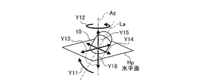
次に、図1に示す操作入力部24の具体的な構成及び動作について説明する。図12(a)は、操作入力部24の正面図であり、図12(b)は、操作入力部24の右側面図である。図13は、操作入力部24の各構成部位の操作によって指示されるカプセル型内視鏡10の動きを示す図である。
Next, a specific configuration and operation of the operation input unit 24 shown in FIG. 1 will be described. 12A is a front view of the operation input unit 24, and FIG. 12B is a right side view of the operation input unit 24. FIG. 13 is a diagram illustrating the movement of the capsule endoscope 10 that is instructed by the operation of each component of the operation input unit 24.
図12(a)に示すように、操作入力部24は、磁界生成部25によるカプセル型内視鏡10の磁気誘導を3次元的に操作するための2つのジョイスティック61、62を備える。ジョイスティック61、62は、上下方向及び左右方向に傾動操作が可能である。
As shown in FIG. 12 (a), the operation input unit 24 includes two joysticks 61 and 62 for three-dimensionally operating the magnetic guidance of the capsule endoscope 10 by the magnetic field generation unit 25. The joysticks 61 and 62 can be tilted in the vertical direction and the horizontal direction.
図12(b)に示すように、ジョイスティック61の背面には、アップボタン64U、ダウンボタン64Bが設けられている。アップボタン64Uは、押圧されることによってカプセル型内視鏡10の上方誘導を指示する誘導指示情報を制御部28に入力し、ダウンボタン64Bは、押圧されることによってカプセル型内視鏡10の下方誘導を指示する誘導指示情報を制御部28に入力する。ジョイスティック61の上部には、キャプチャボタン65が設けられている。キャプチャボタン65は、押圧されることによって、表示部23aに表示されている体内画像をキャプチャする。また、ジョイスティック62の上部には、アプローチボタン66が設けられている。アプローチボタン66は、押圧されることによって、撮像部11Aの撮像対象に対してカプセル型内視鏡10の撮像部11A側を近接させるようにカプセル型内視鏡10を誘導させる誘導指示情報を制御部28に入力する。
As shown in FIG. 12B, an up button 64U and a down button 64B are provided on the back of the joystick 61. When the up button 64U is pressed, guidance instruction information that instructs the capsule endoscope 10 to be guided upward is input to the control unit 28, and when the down button 64B is pressed, the capsule endoscope 10 is moved. Guidance instruction information for instructing downward guidance is input to the control unit 28. On the upper part of the joystick 61, a capture button 65 is provided. When the capture button 65 is pressed, the in-vivo image displayed on the display unit 23a is captured. An approach button 66 is provided on the joystick 62. When the approach button 66 is pressed, it controls guidance instruction information for guiding the capsule endoscope 10 to bring the imaging unit 11A side of the capsule endoscope 10 closer to the imaging target of the imaging unit 11A. Input to the unit 28.
図12(a)に示すように、ジョイスティック61の矢印Y11jに示す上下方向の傾動方向は、図13の矢印Y11のようにカプセル型内視鏡10の先端が鉛直軸Azを通るように首を振るティルティング誘導方向に対応する。操作入力部24から、ジョイスティック61の矢印Y11jの傾動操作に対応する誘導指示情報が制御部28に入力された場合、制御部28は、この誘導指示情報をもとに、ジョイスティック61の傾動方向に応じてカプセル型内視鏡10先端の絶対座標系上における誘導方向を演算し、ジョイスティック61の傾動操作に応じて誘導量を演算する。そして、磁界生成部25は、例えば演算した誘導方向に、演算した誘導量に応じて体外永久磁石25aを回転させるよう、仰角変更部25dを制御する。
As shown in FIG. 12A, the vertical tilt direction indicated by the arrow Y11j of the joystick 61 is such that the tip of the capsule endoscope 10 passes through the vertical axis Az as indicated by the arrow Y11 in FIG. Corresponds to the tilting guidance direction to shake. When guidance instruction information corresponding to the tilting operation of the arrow Y11j of the joystick 61 is input from the operation input unit 24 to the control unit 28, the control unit 28 moves the joystick 61 in the tilting direction based on the guidance instruction information. Accordingly, the guide direction on the absolute coordinate system of the tip of the capsule endoscope 10 is calculated, and the guide amount is calculated according to the tilting operation of the joystick 61. Then, the magnetic field generation unit 25 controls the elevation angle changing unit 25d so as to rotate the extracorporeal permanent magnet 25a in accordance with the calculated induction amount, for example, in the calculated induction direction.
図12(a)に示すように、ジョイスティック61の矢印Y12jに示す左右方向の傾動方向は、図13の矢印Y12のようにカプセル型内視鏡10が鉛直軸Azを中心として回転するローテーション誘導方向に対応する。操作入力部24から、ジョイスティック61の矢印Y12jの傾動操作に対応する誘導指示情報が制御部28に入力された場合、制御部28は、この誘導指示情報をもとに、ジョイスティック61の傾動方向に応じてカプセル型内視鏡10先端の絶対座標系上における誘導方向を演算すると共に、ジョイスティック61の傾動操作に応じて誘導量を演算し、さらに、例えば演算した誘導方向に、演算した誘導量に応じて体外永久磁石25aを旋回させるよう、旋回角変更部25eを制御する。
As shown in FIG. 12A, the horizontal tilt direction indicated by the arrow Y12j of the joystick 61 is the rotation guiding direction in which the capsule endoscope 10 rotates about the vertical axis Az as indicated by the arrow Y12 in FIG. Corresponding to When guidance instruction information corresponding to the tilting operation of the arrow Y12j of the joystick 61 is input from the operation input unit 24 to the control unit 28, the control unit 28 moves in the tilt direction of the joystick 61 based on the guidance instruction information. Accordingly, the guidance direction on the absolute coordinate system of the distal end of the capsule endoscope 10 is calculated, the guidance amount is calculated according to the tilting operation of the joystick 61, and, for example, the calculated guidance direction is set to the calculated guidance direction. Accordingly, the turning angle changing unit 25e is controlled to turn the extracorporeal permanent magnet 25a.
図12(a)に示すように、ジョイスティック62の矢印Y13jに示す上下方向の傾動方向は、図13の矢印Y13のようにカプセル型内視鏡10の長軸Laを水平面Hpに投影した方向に進むホリゾンタルバックワード誘導方向又はホリゾンタルフォワード誘導方向に対応する。操作入力部24から、ジョイスティック62の矢印Y13jの傾動操作に対応する誘導指示情報が制御部28に入力された場合、制御部28は、この誘導指示情報をもとに、ジョイスティック62の傾動方向に応じてカプセル型内視鏡10先端の絶対座標系上における誘導方向及び誘導量を演算し、演算した誘導方向及び誘導量に応じて体外永久磁石25aを並進させるよう、平面位置変更部25bを制御する。
As shown in FIG. 12A, the vertical tilt direction indicated by the arrow Y13j of the joystick 62 is the direction in which the long axis La of the capsule endoscope 10 is projected onto the horizontal plane Hp as indicated by the arrow Y13 in FIG. Corresponds to the forward backward guidance direction or the horizontal forward guidance direction. When guidance instruction information corresponding to the tilting operation of the arrow Y13j of the joystick 62 is input from the operation input unit 24 to the control unit 28, the control unit 28 moves the joystick 62 in the tilting direction based on the guidance instruction information. Accordingly, the guidance direction and the guidance amount on the absolute coordinate system of the tip of the capsule endoscope 10 are calculated, and the planar position changing unit 25b is controlled so that the extracorporeal permanent magnet 25a is translated according to the calculated guidance direction and guidance amount. To do.
図12(a)に示すように、ジョイスティック62の矢印Y14jに示す左右方向の傾動方向は、図13の矢印Y14のようにカプセル型内視鏡10が水平面Hpを、長軸Laを水平面Hpに投影した方向と垂直に進むホリゾンタルライト誘導方向又はホリゾンタルレフト誘導方向に対応する。操作入力部24から、ジョイスティック62の矢印Y14jの傾動操作に対応する誘導指示情報が制御部28に入力された場合、制御部28は、この誘導指示情報をもとに、ジョイスティック62の傾動方向に応じてカプセル型内視鏡10先端の絶対座標系上における誘導方向及び誘導量を演算し、演算した誘導方向及び誘導量に応じて体外永久磁石25aを並進させるよう、平面位置変更部25bを制御する。
As shown in FIG. 12A, the horizontal tilt direction indicated by the arrow Y14j of the joystick 62 is such that the capsule endoscope 10 is in the horizontal plane Hp and the long axis La is in the horizontal plane Hp as indicated by the arrow Y14 in FIG. Corresponds to a horizontal light guiding direction or a horizontal left guiding direction that runs perpendicular to the projected direction. When guidance instruction information corresponding to the tilting operation of the arrow Y14j of the joystick 62 is input from the operation input unit 24 to the control unit 28, the control unit 28 moves the joystick 62 in the tilting direction based on the guidance instruction information. Accordingly, the guidance direction and the guidance amount on the absolute coordinate system of the tip of the capsule endoscope 10 are calculated, and the planar position changing unit 25b is controlled so that the extracorporeal permanent magnet 25a is translated according to the calculated guidance direction and guidance amount. To do.
また、ジョイスティック61の背面には、アップボタン64U及びダウンボタン64Bが設けられている。図12(b)の矢印Y15jに示すようにアップボタン64Uが押圧された場合には、図13に示す鉛直軸Azに沿って矢印Y15のように上に進むアップ動作が指示される。また、図12(b)の矢印Y16jに示すように、ダウンボタン64Bが押圧された場合には、図13に示す鉛直軸Azに沿って矢印Y16のように下に進むダウン動作が指示される。操作入力部24から、アップボタン64U又はダウンボタン64Bの矢印Y15j、Y16jの押圧操作に対応する誘導指示情報が制御部28に入力された場合、制御部28は、この誘導指示情報をもとに、押圧されたボタンに応じて、カプセル型内視鏡10先端の絶対座標系上における誘導方向及び誘導量を演算し、演算した誘導方向及び誘導量に応じて体外永久磁石25aを鉛直方向に並進させるよう、鉛直位置変更部25cを制御する。例えば、アップボタン64Uが押圧された場合、鉛直位置変更部25cは、体外永久磁石25aを鉛直軸Azの下方向(カプセル型内視鏡10から離れる方向)に向かって並進させる。それにより、カプセル型内視鏡10は矢印Y15のように上昇する。一方、ダウンボタン64Bが押圧された場合、鉛直位置変更部25cは、体外永久磁石25aを鉛直軸Azの上方向(カプセル型内視鏡10に近づく方向)に向かって並進させる。それにより、カプセル型内視鏡10は、矢印Y16のように下降する。
Also, an up button 64U and a down button 64B are provided on the back of the joystick 61. When the up button 64U is pressed as indicated by an arrow Y15j in FIG. 12B, an up operation is designated that proceeds upward as indicated by an arrow Y15 along the vertical axis Az shown in FIG. When the down button 64B is pressed as shown by an arrow Y16j in FIG. 12B, a down operation is instructed to move downward as shown by an arrow Y16 along the vertical axis Az shown in FIG. . When guidance instruction information corresponding to the pressing operation of the arrows Y15j and Y16j of the up button 64U or the down button 64B is input from the operation input unit 24 to the control unit 28, the control unit 28 uses the guidance instruction information. The guidance direction and the guidance amount on the absolute coordinate system of the tip of the capsule endoscope 10 are calculated according to the pressed button, and the extracorporeal permanent magnet 25a is translated in the vertical direction according to the calculated guidance direction and the guidance amount. The vertical position changing unit 25c is controlled so as to make it. For example, when the up button 64U is pressed, the vertical position changing unit 25c translates the extracorporeal permanent magnet 25a in the downward direction of the vertical axis Az (direction away from the capsule endoscope 10). Thereby, the capsule endoscope 10 is raised as indicated by an arrow Y15. On the other hand, when the down button 64B is pressed, the vertical position changing unit 25c translates the extracorporeal permanent magnet 25a in the upward direction of the vertical axis Az (direction approaching the capsule endoscope 10). Thereby, the capsule endoscope 10 is lowered as indicated by an arrow Y16.
なお、操作入力部24は、このようなジョイスティック61、62と共に、各種操作ボタンやキーボード等からなる入力デバイスをさらに有しても良い。
The operation input unit 24 may further include an input device including various operation buttons, a keyboard, and the like, in addition to the joysticks 61 and 62.
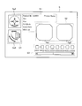
図14は、表示部23aに表示されるメニュー画面Sの表示例を示す模式図である。このメニュー画面Sには、左上方の領域S1に被検体101の患者名、患者ID、生年月日、性別、年齢等の各被検体情報が表示され、中央の領域S2には、撮像部11Aが撮像した生体画像Sg1が左側に表示され、撮像部11Bが撮像した生体画像Sg2が右側に表示され、領域S2の下方の領域S3には、キャプチャボタン65の押圧操作によってキャプチャされた各画像が、キャプチャ時間とともに縮小表示され、左側の領域S4にカプセル型内視鏡10の姿勢図として鉛直面における姿勢図Sg3、水平面における姿勢図Sg4が表示される。各姿勢図Sg3、Sg4に表示されるカプセル型内視鏡10の傾斜角及び方位角は、操作入力部24の誘導指示情報に対応する傾斜角及び方位角を表示している。実施の形態1においては、操作入力部24からの入力量が誘導する力に反映されるため、表示されるカプセル型内視鏡10の傾斜角及び方位角は、実際のカプセル型内視鏡10の傾斜角及び方位角とほぼ同じものと考えることができ、操作者の誘導指示補助も向上する。なお、この姿勢図Sg3、Sg4には、カプセル型内視鏡10を誘導可能な方向が矢印で示され、いずれかの誘導方向の操作入力があった場合には、入力された方向に対応する矢印の表示色を変えて、操作者の操作を補助している。
FIG. 14 is a schematic diagram showing a display example of the menu screen S displayed on the display unit 23a. In this menu screen S, each subject information such as the patient name, patient ID, date of birth, sex, age, etc. of the subject 101 is displayed in the upper left region S1, and the imaging unit 11A is displayed in the central region S2. Is displayed on the left side, the biological image Sg2 captured by the imaging unit 11B is displayed on the right side, and in the region S3 below the region S2, each image captured by the pressing operation of the capture button 65 is displayed. The image is reduced and displayed with the capture time, and the posture diagram Sg3 in the vertical plane and the posture diagram Sg4 in the horizontal plane are displayed as the posture diagram of the capsule endoscope 10 in the left region S4. The tilt angle and azimuth angle of the capsule endoscope 10 displayed in the posture diagrams Sg3 and Sg4 display the tilt angle and azimuth angle corresponding to the guidance instruction information of the operation input unit 24. In the first embodiment, since the input amount from the operation input unit 24 is reflected in the guiding force, the tilt angle and the azimuth angle of the displayed capsule endoscope 10 are the actual capsule endoscope 10. The tilt angle and the azimuth angle are substantially the same, and guidance assistance for the operator is improved. In the posture diagrams Sg3 and Sg4, directions in which the capsule endoscope 10 can be guided are indicated by arrows, and when there is an operation input in any one of the guidance directions, it corresponds to the input direction. The display color of the arrow is changed to assist the operator's operation.
次に、図1に示す誘導システム1の動作について説明する。図15は、誘導システム1の動作を示すフローチャートである。
Next, the operation of the guidance system 1 shown in FIG. 1 will be described. FIG. 15 is a flowchart showing the operation of the guidance system 1.
カプセル型医療装置誘導システム1が起動すると、まず、ステップS101において、誘導装置20の制御部28は、遮蔽状態検知部27の出力結果から、誘導装置20が磁界遮蔽状態(図3参照)にあることを確認する。
When the capsule medical device guidance system 1 is activated, first, in step S101, the control unit 28 of the guidance device 20 indicates that the guidance device 20 is in the magnetic field shielding state (see FIG. 3) based on the output result of the shielding state detection unit 27. Make sure.
続くステップS102において、制御部28は、有効磁界領域100における磁界強度が最小となる位置(初期位置)に体外永久磁石25aが配置されていることを確認する。なお、体外永久磁石25aが初期位置にないとき、制御部28は、鉛直位置変更部25cを制御して、体外永久磁石25aを初期位置に移動させる。
In subsequent step S102, the control unit 28 confirms that the extracorporeal permanent magnet 25a is disposed at a position (initial position) where the magnetic field strength in the effective magnetic field region 100 is minimized. When the extracorporeal permanent magnet 25a is not in the initial position, the control unit 28 controls the vertical position changing unit 25c to move the extracorporeal permanent magnet 25a to the initial position.
ステップS103において、被検体101がベッド20aに載置されたことを示す信号が操作入力部24から入力されると、制御部28は、被検体101がベッド20aに載置されたことを認識する。この信号は、所定のユーザ操作(例えば、ベッド載置確認ボタンの押下)により入力されるようにしても良い。或いは、ベッド20aが所定の状態になった際(例えば、ベッド20aの被検体載置面に圧力センサを設け、この圧力センサの出力値が所定の閾値を超えた際)に入力されるようにしても良い。
In step S103, when a signal indicating that the subject 101 is placed on the bed 20a is input from the operation input unit 24, the control unit 28 recognizes that the subject 101 is placed on the bed 20a. . This signal may be input by a predetermined user operation (for example, pressing of a bed placement confirmation button). Alternatively, the signal is input when the bed 20a is in a predetermined state (for example, when a pressure sensor is provided on the subject placement surface of the bed 20a and the output value of the pressure sensor exceeds a predetermined threshold). May be.
ステップS104において、カプセル型内視鏡10の電源がオンされると、誘導装置20は、カプセル型内視鏡10から送信された無線信号を受信し、カプセル型内視鏡10が撮像した画像を取得できることを確認する。ここで、カプセル型内視鏡10のオンはカプセル型内視鏡10内に配置された電源部18の磁気スイッチや光スイッチがオンされることにより実現される。即ち、この磁気スイッチや光スイッチを起動するための外部からの磁気や光の印加がなされる。
In step S104, when the power supply of the capsule endoscope 10 is turned on, the guide device 20 receives the wireless signal transmitted from the capsule endoscope 10 and captures an image captured by the capsule endoscope 10. Confirm that it can be obtained. Here, the capsule endoscope 10 is turned on by turning on a magnetic switch or an optical switch of the power supply unit 18 disposed in the capsule endoscope 10. That is, external magnetism or light is applied to activate the magnetic switch or optical switch.
ステップS105において、カプセル型内視鏡10が被検体101に嚥下されたことを示す信号が操作入力部24から入力されると、制御部28は、カプセル型内視鏡10が被検体101に嚥下されたことを認識する。この信号は、所定のユーザ操作(例えば、カプセル嚥下確認ボタンの押下)により入力されるようにしても良い。或いは、カプセル型内視鏡10から送信された画像データが所定の状態になった際(例えば、画像の色特徴量が体内であることを示す所定の状態になった際)に、当該信号が入力されるようにしても良い。
In step S <b> 105, when a signal indicating that the capsule endoscope 10 has been swallowed by the subject 101 is input from the operation input unit 24, the control unit 28 swallows the capsule endoscope 10 to the subject 101. Recognize that This signal may be input by a predetermined user operation (for example, pressing a capsule swallowing confirmation button). Alternatively, when the image data transmitted from the capsule endoscope 10 is in a predetermined state (for example, when the color feature amount of the image is in a predetermined state indicating that it is in the body), the signal is It may be input.
ステップS106において、検査開始を示す信号が操作入力部24から入力されると、制御部28は、誘導装置20を磁界生成状態に遷移させるよう、各部を制御する。この検査開始を示す信号は、例えば、操作入力部24の所定のボタン(例えば検査開始ボタン)の押下といった1アクションや、ジョイスティック61、62等による操作によって入力されるようにしても良い。
In step S106, when a signal indicating the start of inspection is input from the operation input unit 24, the control unit 28 controls each unit so that the guidance device 20 is shifted to the magnetic field generation state. The signal indicating the start of inspection may be input by one action such as pressing a predetermined button (for example, inspection start button) of the operation input unit 24 or an operation using the joysticks 61 and 62, for example.
これにより、磁界生成部25と有効磁界領域100との間に配置されていた磁性体部材26aが抜去され、誘導装置20は磁界生成状態となる。このとき、磁界生成部25は初期位置にあるため(ステップS102参照)、有効磁界領域100に生成される磁界の強度は最小となる。これによりカプセル型内視鏡10に対して強度の大きな磁界が急激に印加されるのを避けることができる。以下、磁界生成部25が初期位置にある磁界生成状態(図16参照)を、弱磁界生成状態という。
Thereby, the magnetic body member 26a disposed between the magnetic field generation unit 25 and the effective magnetic field region 100 is removed, and the guidance device 20 enters a magnetic field generation state. At this time, since the magnetic field generation unit 25 is in the initial position (see step S102), the intensity of the magnetic field generated in the effective magnetic field region 100 is minimized. Thereby, it is possible to avoid a sudden application of a strong magnetic field to the capsule endoscope 10. Hereinafter, the magnetic field generation state (see FIG. 16) in which the magnetic field generation unit 25 is in the initial position is referred to as a weak magnetic field generation state.
ステップS107において、制御部28は、操作入力部24から入力された情報(例えば、左側臥位といった被検体101の体位情報)を受け付け、受け付けた情報を表示装置23aに表示させる。この際、制御部28は、カプセル型内視鏡10の絶対座標系(重力方向を基準とする座標系)と該情報とに基づいて被検体101内の相対座標系を取得し、この相対座標系に基づき、被検体101内における観察方向や観察部位を推定するといった演算処理を行っても良い。
In step S107, the control unit 28 receives information input from the operation input unit 24 (for example, the posture information of the subject 101 such as the left-side position), and displays the received information on the display device 23a. At this time, the control unit 28 acquires a relative coordinate system in the subject 101 based on the absolute coordinate system (coordinate system based on the direction of gravity) of the capsule endoscope 10 and the information, and the relative coordinates. Based on the system, a calculation process such as estimating an observation direction and an observation site in the subject 101 may be performed.
ステップS108において、制御部28は、カプセル型内視鏡10の誘導を開始し、操作入力部24から入力された誘導指示情報に従って体外永久磁石25aの位置、仰角θ、及び旋回角ψを制御する。なお、この際、体外永久磁石25aを初期位置よりも上方に移動させることにより、有効磁界領域100に、より強度の大きな磁界が形成されるようになる。これにより、誘導装置20は、弱磁界生成状態から通常の磁界生成状態に遷移する。
In step S108, the control unit 28 starts guiding the capsule endoscope 10, and controls the position of the extracorporeal permanent magnet 25a, the elevation angle θ, and the turning angle ψ according to the guidance instruction information input from the operation input unit 24. . At this time, by moving the extracorporeal permanent magnet 25 a upward from the initial position, a magnetic field having a higher strength is formed in the effective magnetic field region 100. Thereby, the guidance device 20 makes a transition from the weak magnetic field generation state to the normal magnetic field generation state.
ステップS109において、制御部28は、カプセル型内視鏡10から送信された無線信号を順次受信し、カプセル型内視鏡10が撮像した画像を表示部23aに表示させる。ユーザは、この画像を参照しながら操作入力部24を操作することにより、カプセル型内視鏡10を所望の位置、傾斜角、及び方位角に誘導することができる。
In step S109, the control unit 28 sequentially receives wireless signals transmitted from the capsule endoscope 10 and causes the display unit 23a to display an image captured by the capsule endoscope 10. The user can guide the capsule endoscope 10 to a desired position, tilt angle, and azimuth by operating the operation input unit 24 while referring to this image.
なお、ユーザは、必要に応じて被検体101の体位を変更しても良い。この場合、操作ボタンの押下や、キーボード等を用いた姿勢情報の入力といった操作入力部24に対する所定の操作により、被検体101の体位を変更した旨の信号を誘導装置20に入力することができる。制御部28は、操作入力部24から被検体101の体位を変更した旨の信号が入力されると、体外永久磁石25aを一旦初期位置に戻し、弱磁界生成状態とする。これにより、体位変更後のカプセル型内視鏡10に強度の大きな磁界が急激に印加されるのを避けることができる。
Note that the user may change the posture of the subject 101 as necessary. In this case, a signal indicating that the posture of the subject 101 has been changed can be input to the guidance device 20 by a predetermined operation on the operation input unit 24 such as pressing an operation button or inputting posture information using a keyboard or the like. . When a signal indicating that the posture of the subject 101 has been changed is input from the operation input unit 24, the control unit 28 once returns the extracorporeal permanent magnet 25a to the initial position, and enters a weak magnetic field generation state. Thereby, it is possible to avoid sudden application of a strong magnetic field to the capsule endoscope 10 after the change of body position.
ステップS110において、制御部28は、緊急停止トリガがオンにされたか否かを判断する。ここで、緊急停止トリガは、例えば所定のボタン(緊急停止ボタン)の押下に応じて操作入力部24から入力される緊急停止信号であっても良いし、ステップS103において一旦認識された被検体101の載置が認識されなくなったことを示す信号(例えば、被検体載置面に設けられた圧力センサの出力値の低下)であっても良い。この他、地震等による振動の検出や、誘導装置20における急激な電圧の降下を緊急停止トリガとしても良い。
In step S110, the control unit 28 determines whether or not the emergency stop trigger is turned on. Here, the emergency stop trigger may be an emergency stop signal input from the operation input unit 24 in response to pressing of a predetermined button (emergency stop button), for example, or the subject 101 once recognized in step S103. May be a signal (for example, a decrease in the output value of the pressure sensor provided on the subject placement surface) indicating that the placement of the subject is no longer recognized. In addition, detection of vibration due to an earthquake or the like, or a rapid voltage drop in the guidance device 20 may be used as an emergency stop trigger.
緊急停止トリガがオンにされた場合(ステップS110:Yes)、制御部28は、緊急停止トリガがオンにされた旨の報知を表示部23aや報知部23bに実行させると共に、遮蔽部26を制御して、誘導装置20を磁界遮蔽状態(緊急遮蔽)に遷移させる(ステップS111)。具体的な報知方法としては、「緊急停止します」といった視覚情報による警告を表示部23aに表示させても良いし、照明の点滅といった別の視覚情報による警告や、音声又は警告音といった聴覚情報による警告を報知部23bに実行させても良いし、或いは、これらの両方を実行させても良い。その後、誘導システム1の動作は、ステップS116に移行する。一方、緊急停止トリガがオンにされない場合(ステップS110:No)、誘導システム1の動作はステップS112に移行する。
When the emergency stop trigger is turned on (step S110: Yes), the control unit 28 causes the display unit 23a and the notification unit 23b to perform notification that the emergency stop trigger is turned on and controls the shielding unit 26. Then, the guidance device 20 is changed to the magnetic field shielding state (emergency shielding) (step S111). As a specific notification method, a warning based on visual information such as “I will urgently stop” may be displayed on the display unit 23a, a warning based on another visual information such as lighting blinking, and audio information such as sound or warning sound. May be executed by the notification unit 23b, or both of them may be executed. Thereafter, the operation of the guidance system 1 proceeds to step S116. On the other hand, when the emergency stop trigger is not turned on (step S110: No), the operation of the guidance system 1 proceeds to step S112.
ステップS112において、制御部28は、全ての画像の取得が完了した旨を示す信号が操作入力部24から入力されたか否かを判断する。この信号は、所定のユーザ操作(例えば、画像取得完了ボタンや誘導終了ボタンの押下)により入力されるようにしても良い。或いは、カプセル型内視鏡10から受信した画像が所定の枚数に達した場合や、カプセル型内視鏡10の電源がオンにされてから所定の時間が経過した場合に、当該信号が入力されるようにしても良い。
In step S112, the control unit 28 determines whether or not a signal indicating that acquisition of all images has been completed is input from the operation input unit 24. This signal may be input by a predetermined user operation (for example, pressing of an image acquisition completion button or a guidance end button). Alternatively, when a predetermined number of images have been received from the capsule endoscope 10 or when a predetermined time has elapsed since the capsule endoscope 10 was turned on, the signal is input. You may make it.
全ての画像の取得が完了した場合(ステップS112:Yes)、制御部28は、磁界生成部25の動作を停止させ、カプセル型内視鏡10の誘導を停止すると共に、体外永久磁石25aを初期位置に戻して誘導装置20を弱磁界生成状態に遷移させる(ステップS113)。
When acquisition of all images is completed (step S112: Yes), the control unit 28 stops the operation of the magnetic field generation unit 25, stops the guidance of the capsule endoscope 10, and initially sets the extracorporeal permanent magnet 25a. Returning to the position, the guidance device 20 is shifted to the weak magnetic field generation state (step S113).
一方、全ての画像が未だ取得されていない場合(ステップS112:No)、制御部28は、操作入力部24から体位情報が新たに入力されたか否かを判断する(ステップS114)。体位情報が新たに入力された場合(ステップS114:Yes)、制御部28は、体外永久磁石25aを初期位置に戻して誘導装置20を弱磁界生成状態に遷移させる(ステップS115)。その後、誘導システム1の動作は、ステップS109に移行する。一方、体位情報が新たに入力されない場合(ステップS114:No)、誘導システム1の動作は、そのままステップS109に移行する。
On the other hand, when all the images have not been acquired yet (step S112: No), the control unit 28 determines whether or not body position information is newly input from the operation input unit 24 (step S114). When the body position information is newly input (step S114: Yes), the control unit 28 returns the extracorporeal permanent magnet 25a to the initial position and causes the guidance device 20 to transition to the weak magnetic field generation state (step S115). Thereafter, the operation of the guidance system 1 proceeds to step S109. On the other hand, when the body position information is not newly input (step S114: No), the operation of the guidance system 1 proceeds to step S109 as it is.
ステップS116において、制御部28は、遮蔽部26を制御して、誘導装置20を磁界遮蔽状態に遷移させる。これにより、誘導システム1の動作が終了する。その後、ユーザは、被検体101をベッド20aから降ろす。
In step S116, the control unit 28 controls the shielding unit 26 to change the guidance device 20 to the magnetic field shielding state. Thereby, operation | movement of the guidance system 1 is complete | finished. Thereafter, the user drops the subject 101 from the bed 20a.
なお、以上の説明において、磁界生成状態と磁界遮蔽状態との遷移は、制御部28の制御の下で遮蔽部26が行ったが、ユーザが手動で磁性体部材26aを移動させることによりこの遷移を行っても良い。
In the above description, the transition between the magnetic field generation state and the magnetic field shielding state is performed by the shielding unit 26 under the control of the control unit 28, but this transition is performed by the user manually moving the magnetic member 26a. May be performed.
次に、体外永久磁石25aの形状に関する条件について説明する。
本発明者らは、カプセル型内視鏡10を誘導するための磁界を体外永久磁石25aから効率的に発生させるため、永久磁石の形状(縦・横・高さの比)と発生磁界との関係をシミュレーションにより求めた。図17は、このシミュレーションにおける評価項目を説明するための模式図である。図17に示すように、本シミュレーションにおいては、永久磁石の磁化方向をx軸方向、シミュレーション位置と対向する面PL2の磁化方向と直交する方向をy軸方向、面PL2と直交する方向をz軸方向に設定し、シミュレーション位置における磁界強度と、同位置におけるz軸方向、x軸方向、及びy軸方向における各磁気勾配とを評価した。なお、磁気強度は、カプセル型内視鏡10の傾斜角及び方位角を変更する際の誘導に関与する。z軸方向の磁気勾配は、カプセル型内視鏡10に対するz軸方向における誘導に関与する。x軸方向の磁気勾配は、カプセル型内視鏡10に対するx軸方向における誘導に関与する。y軸方向の磁気勾配は、カプセル型内視鏡10に対するy軸方向における誘導に関与する。 Next, conditions regarding the shape of the extracorporealpermanent magnet 25a will be described.
In order to efficiently generate a magnetic field for guiding thecapsule endoscope 10 from the extracorporeal permanent magnet 25a, the inventors of the present invention have a relationship between the shape of the permanent magnet (ratio of vertical / horizontal / height) and the generated magnetic field. The relationship was obtained by simulation. FIG. 17 is a schematic diagram for explaining evaluation items in this simulation. As shown in FIG. 17, in this simulation, the magnetization direction of the permanent magnet is the x-axis direction, the direction orthogonal to the magnetization direction of the surface PL2 facing the simulation position is the y-axis direction, and the direction orthogonal to the surface PL2 is the z-axis. The magnetic field intensity at the simulation position and each magnetic gradient in the z-axis direction, the x-axis direction, and the y-axis direction at the same position were evaluated. The magnetic intensity is involved in guidance when changing the tilt angle and azimuth angle of the capsule endoscope 10. The magnetic gradient in the z-axis direction is involved in guidance in the z-axis direction with respect to the capsule endoscope 10. The magnetic gradient in the x-axis direction is involved in guidance in the x-axis direction with respect to the capsule endoscope 10. The magnetic gradient in the y-axis direction is involved in guidance in the y-axis direction with respect to the capsule endoscope 10.
本発明者らは、カプセル型内視鏡10を誘導するための磁界を体外永久磁石25aから効率的に発生させるため、永久磁石の形状(縦・横・高さの比)と発生磁界との関係をシミュレーションにより求めた。図17は、このシミュレーションにおける評価項目を説明するための模式図である。図17に示すように、本シミュレーションにおいては、永久磁石の磁化方向をx軸方向、シミュレーション位置と対向する面PL2の磁化方向と直交する方向をy軸方向、面PL2と直交する方向をz軸方向に設定し、シミュレーション位置における磁界強度と、同位置におけるz軸方向、x軸方向、及びy軸方向における各磁気勾配とを評価した。なお、磁気強度は、カプセル型内視鏡10の傾斜角及び方位角を変更する際の誘導に関与する。z軸方向の磁気勾配は、カプセル型内視鏡10に対するz軸方向における誘導に関与する。x軸方向の磁気勾配は、カプセル型内視鏡10に対するx軸方向における誘導に関与する。y軸方向の磁気勾配は、カプセル型内視鏡10に対するy軸方向における誘導に関与する。 Next, conditions regarding the shape of the extracorporeal
In order to efficiently generate a magnetic field for guiding the
また、本シミュレーションにおいては、直方体(立方体を含む)の永久磁石を用いた。図18は、シミュレーションに用いた永久磁石の各辺の長さの比を示す表である。図18に示す「x軸方向の長さLx」はx軸と平行な辺の長さLxを示し、「y軸方向の長さLy」はy軸と平行な辺の長さLyを示し、「z軸方向の長さLz」はz軸と平行な辺の長さLzを示す(図17参照)。また、図18の「タイプ」の欄には、各永久磁石の辺の内、長いものが左から順に示されている。例えば、タイプ「x-y-z」は、x軸と平行な辺が最も長く、z軸と平行な辺が最も短い直方体形状を示す(Lx>Ly>Lz)。なお、タイプ「xyz」は、全ての辺の長さが等しい立方体を示す(Lx=Ly=Lz)。
In this simulation, a rectangular parallelepiped (including a cube) permanent magnet was used. FIG. 18 is a table showing the ratio of the lengths of the sides of the permanent magnet used in the simulation. "Length L x in the x-axis direction" shown in FIG. 18 indicates the length L x of the x-axis and sides parallel, "length L y in the y-axis direction" is the length of the sides parallel to the y-axis L indicates y, "the length L z of the z-axis direction" indicates the length L z of parallel sides and z-axis (see FIG. 17). Further, in the “type” column of FIG. 18, the long ones of the sides of each permanent magnet are shown in order from the left. For example, the type “xyz” indicates a rectangular parallelepiped shape having the longest side parallel to the x-axis and the shortest side parallel to the z-axis (L x > L y > L z ). Note that the type “xyz” indicates a cube with all sides having the same length (L x = L y = L z ).
図19は、図18に示す各永久磁石の磁界強度を示すグラフである。図20は、図18に示す各永久磁石により発生するz軸方向における磁気勾配を示すグラフである。図21は、図18に示す各永久磁石により発生するx軸方向における磁気勾配を示すグラフである。図22は、図18に示す各永久磁石により発生するy軸方向における磁気勾配を示すグラフである。なお、図19において、磁界強度の値は正規化されている。また、図20~図22を通して、磁気勾配の値は正規化されている。図21及び図22において、横軸は、永久磁石の中心を通るz軸方向の軸(中心軸)からの距離を正規化した値を示している。
FIG. 19 is a graph showing the magnetic field strength of each permanent magnet shown in FIG. FIG. 20 is a graph showing the magnetic gradient in the z-axis direction generated by each permanent magnet shown in FIG. FIG. 21 is a graph showing the magnetic gradient in the x-axis direction generated by each permanent magnet shown in FIG. FIG. 22 is a graph showing a magnetic gradient in the y-axis direction generated by each permanent magnet shown in FIG. In FIG. 19, the value of the magnetic field strength is normalized. Further, the magnetic gradient values are normalized through FIGS. 21 and 22, the horizontal axis indicates a value obtained by normalizing the distance from the axis (center axis) in the z-axis direction passing through the center of the permanent magnet.
カプセル型内視鏡10の傾斜角及び方位角の制御を効率的に行うためには、永久磁石が発生する磁界強度が強いことが好ましい。この点において、図19に示すように、比較的大きい磁界強度が得られた磁石は、タイプy-x-z及びタイプx-y-zであった。従って、カプセル型内視鏡10の傾斜角及び方位角の制御に適した形状は、z軸方向の長さLzがy軸方向の長さLyよりも短い形状であることがわかる。さらには、z軸方向の長さLzがx軸方向及びy軸方向の長さLx、Lyよりも短い、平たい形状がより好ましいと言える。
In order to efficiently control the tilt angle and azimuth angle of the capsule endoscope 10, it is preferable that the magnetic field intensity generated by the permanent magnet is strong. In this regard, as shown in FIG. 19, the magnets that obtained a relatively large magnetic field strength were the type xyz and the type xyz. Therefore, it can be seen that the shape suitable for controlling the tilt angle and the azimuth angle of the capsule endoscope 10 is a shape in which the length L z in the z-axis direction is shorter than the length L y in the y-axis direction. Furthermore, it can be said that a flat shape in which the length L z in the z-axis direction is shorter than the lengths L x and L y in the x-axis direction and the y-axis direction is more preferable.
また、カプセル型内視鏡10の傾斜角を変化させる(即ち、永久磁石をy軸と平行な軸で回転させる)場合には、y軸と直交するzx平面への投影面積が小さい方が、回転時の永久磁石の移動領域を小さくすることができて好ましい。従って、x軸方向の長さLxを短くする方が良い。この場合、永久磁石をより被検体101に近づけて設置することができるので、強度の高い磁界を被検体101内に効率良く生成することができ、磁界生成部25を小型化することができる。
Further, when the tilt angle of the capsule endoscope 10 is changed (that is, when the permanent magnet is rotated on an axis parallel to the y axis), the smaller the projected area on the zx plane orthogonal to the y axis, The moving area of the permanent magnet during rotation can be reduced, which is preferable. Therefore, it is better to reduce the length L x of the x-axis direction. In this case, since the permanent magnet can be installed closer to the subject 101, a high-intensity magnetic field can be efficiently generated in the subject 101, and the magnetic field generator 25 can be downsized.
カプセル型内視鏡10の鉛直方向における位置制御を行うためには、鉛直方向における磁気勾配が大きい方が好ましい。この点において、図20に示すように、z軸方向において比較的大きな磁気勾配が得られた磁石は、タイプy-x-z及びタイプx-y-zであった。従って、カプセル型内視鏡10の鉛直方向における位置制御に適した形状は、z軸方向の長さLzを短くした平たい形状であることがわかる。
In order to control the position of the capsule endoscope 10 in the vertical direction, it is preferable that the magnetic gradient in the vertical direction is large. In this regard, as shown in FIG. 20, the magnets that obtained a relatively large magnetic gradient in the z-axis direction were the type yz and the type xy. Therefore, it can be seen that the shape suitable for the position control in the vertical direction of the capsule endoscope 10 is a flat shape in which the length L z in the z-axis direction is shortened.
カプセル型内視鏡10の水平方向における位置制御を行うためには、水平方向における磁気勾配が大きい方が好ましい。この点において、図21に示すように、x軸方向において比較的大きな磁気勾配が得られた磁石は、タイプy-x-z及びタイプy-z-xであった。なお、タイプx-z-y及びタイプx-y-zの場合、永久磁石から離れた位置に磁気勾配のピークが形成されることがわかった。また、図22に示すように、y軸方向において比較的大きな磁気勾配が得られた磁石は、タイプy-x-z及びタイプx-y-zであった。これより、カプセル型内視鏡10の水平方向における制御に適した形状は、x軸方向及びz軸方向の長さLx、Lzと比較して、y軸方向の長さLyが長い形状であることがわかる。また、x軸方向の長さLxは、y軸方向及びz軸方向の長さLy、Lzと比較して、あまり長くしない方が好ましいと言える。
In order to control the position of the capsule endoscope 10 in the horizontal direction, it is preferable that the magnetic gradient in the horizontal direction is large. In this respect, as shown in FIG. 21, the magnets having a relatively large magnetic gradient in the x-axis direction were of type yz and type yzx. In the case of type xyz and type xyz, it was found that a magnetic gradient peak was formed at a position away from the permanent magnet. Further, as shown in FIG. 22, magnets with a relatively large magnetic gradient in the y-axis direction were of type yxz and type xyz. Thus, the shape suitable for control in the horizontal direction of the capsule endoscope 10 has a longer length L y in the y-axis direction than the lengths L x and L z in the x-axis direction and the z-axis direction. It turns out that it is a shape. Further, it can be said that the length L x in the x-axis direction is preferably not so long as compared to the lengths L y and L z in the y-axis direction and the z-axis direction.
上記シミュレーションの結果から、カプセル型内視鏡10の制御に適した体外永久磁石25aの形状は、y軸方向の長さが最も長く、z軸方向の長さが最も短い平板状であることがわかった。そこで、本発明者らは、続いて、体外永久磁石25aの各辺の長さの好適な比率を求めるための別のシミュレーションを行った。
From the simulation results, the shape of the extracorporeal permanent magnet 25a suitable for controlling the capsule endoscope 10 is a flat plate having the longest length in the y-axis direction and the shortest length in the z-axis direction. all right. Therefore, the inventors subsequently performed another simulation for obtaining a suitable ratio of the lengths of the sides of the extracorporeal permanent magnet 25a.
図23は、別のシミュレーションに用いた永久磁石の各辺の長さの比を示す表である。図23に示す「x軸方向の長さLx」はx軸(磁化方向)と平行な辺の長さLxに対応し、「y軸方向の長さLy」はy軸と平行な辺の長さLyに対応し、「z軸方向の長さLz」はz軸と平行な辺の長さLzに対応する(図17参照)。また、図23の「タイプ」の欄には、各永久磁石の辺の内、長いものが左から順に示されており、括弧の中の数値は、x軸方向の長さに対するz軸方向の長さの比率を示している。図23に示すように、このシミュレーションにおいては、いずれも、y軸方向と平行な辺が最も長く、z軸方向と平行な辺が最も短い直方体の永久磁石を用いている。
FIG. 23 is a table showing the ratio of the lengths of the sides of the permanent magnet used in another simulation. The “length L x in the x-axis direction” shown in FIG. 23 corresponds to the length L x of the side parallel to the x-axis (magnetization direction), and the “length L y in the y-axis direction” is parallel to the y-axis. This corresponds to the side length L y , and the “length L z in the z-axis direction” corresponds to the side length L z parallel to the z-axis (see FIG. 17). In the “type” column of FIG. 23, the long sides of the sides of each permanent magnet are shown in order from the left, and the numerical values in parentheses indicate the z-axis direction length relative to the x-axis direction length. The ratio of length is shown. As shown in FIG. 23, in this simulation, a cuboid permanent magnet having the longest side parallel to the y-axis direction and the shortest side parallel to the z-axis direction is used.
図24は、図23に示す各永久磁石の磁界強度を示すグラフである。図25は、図23に示す各永久磁石により発生するz軸方向における磁気勾配を示すグラフである。図26は、図23に示す各永久磁石により発生するx軸方向における磁気勾配を示すグラフである。図27は、図23に示す各永久磁石により発生するy軸方向における磁気勾配を示すグラフである。なお、図24において、磁界強度の値は正規化されている。また、図25~図27を通して、磁気勾配の値は正規化されている。図26及び図27において、横軸は、永久磁石の中心を通るz軸方向の軸(中心軸)からの距離を正規化した値を示している。
FIG. 24 is a graph showing the magnetic field strength of each permanent magnet shown in FIG. FIG. 25 is a graph showing the magnetic gradient in the z-axis direction generated by each permanent magnet shown in FIG. FIG. 26 is a graph showing the magnetic gradient in the x-axis direction generated by each permanent magnet shown in FIG. FIG. 27 is a graph showing a magnetic gradient in the y-axis direction generated by each permanent magnet shown in FIG. In FIG. 24, the value of the magnetic field strength is normalized. In addition, the magnetic gradient values are normalized through FIGS. 26 and 27, the horizontal axis represents a value obtained by normalizing the distance from the z-axis direction axis (center axis) passing through the center of the permanent magnet.
図24及び図25に示すように、磁界強度及びz軸方向における磁気勾配については、いずれも良好な結果が得られており、永久磁石の各辺の長さの比率を変化させることによる効果は小さいことがわかる。
As shown in FIGS. 24 and 25, good results have been obtained for both the magnetic field strength and the magnetic gradient in the z-axis direction, and the effect of changing the ratio of the length of each side of the permanent magnet is as follows. I understand that it is small.
一方、図26に示すように、永久磁石のz軸方向の長さLzに対し、y軸方向の長さLyを長くするほど(例えば、タイプy-x-z(33)及びタイプy-x-z(50))、x軸方向における磁気勾配が著しく向上することがわかる。一方、この場合、この比率が極端になると(例えば、タイプy-x-z(33))、図27に示すように、y軸方向における磁気勾配が悪化することがわかる。しかしながら、y軸方向における磁気勾配に対してx軸方向における磁気勾配の値は小さいため、各軸方向における磁気勾配のバランスを考慮して、y軸方向の長さLyとz軸方向の長さLzの比を決定すれば良い。
On the other hand, as shown in FIG. 26, as the length L y in the y-axis direction is made longer than the length L z in the z-axis direction of the permanent magnet (for example, type yxz (33) and type y). −xz (50)), the magnetic gradient in the x-axis direction is significantly improved. On the other hand, in this case, when this ratio becomes extreme (for example, type yxz (33)), it can be seen that the magnetic gradient in the y-axis direction deteriorates as shown in FIG. However, since the value of the magnetic gradient in the x-axis direction is smaller than the magnetic gradient in the y-axis direction, the length L y in the y-axis direction and the length in the z-axis direction are considered in consideration of the balance of the magnetic gradient in each axis direction. The ratio of the length L z may be determined.
図28は、z軸方向の長さLzに対するy軸方向の長さLyとの比率Ly/Lzと、タイプy-x-z(33)の永久磁石の磁界強度に対する上記各比率を有する永久磁石の磁界強度の比率との関係を示すグラフである。図28に示すように、z軸方向の長さLzに対するy軸方向の長さLyが1.5倍になると、タイプy-x-z(33)の永久磁石、即ち、長さLzに対する長さLyが十分に長い永久磁石が発生する磁界強度に対し、90%程度の磁界強度を発生させることができる。さらに、z軸方向の長さLzに対するy軸方向の長さLyが3倍以上になると、上記磁界強度の比率が95%となる。従って、好ましい永久磁石の形状として、z軸方向の長さLzに対するy軸方向の長さLyを1.5倍以上又は3倍以上とすると良い。
FIG. 28 shows the ratio L y / L z of the length L y in the y-axis direction to the length L z in the z-axis direction and the above-mentioned ratios to the magnetic field strength of the permanent magnet of type yxz (33). It is a graph which shows the relationship with the ratio of the magnetic field strength of the permanent magnet which has. As shown in FIG. 28, when the length L y in the y-axis direction is 1.5 times the length L z in the z-axis direction, the permanent magnet of type yxz (33), that is, the length L magnetic field strength length L y for z is sufficiently long permanent magnet occurs hand, it is possible to generate a magnetic field strength of about 90%. Further, when the length L y in the y-axis direction with respect to the length L z in the z-axis direction becomes three times or more, the ratio of the magnetic field strength becomes 95%. Therefore, as a preferable shape of the permanent magnet, the length L y in the y-axis direction with respect to the length L z in the z-axis direction is preferably 1.5 times or more or 3 times or more.
上記シミュレーションの結果を基に、体外永久磁石25aの形状を、y軸方向の長さLyが最も長い形状(Ly>Lx、Ly>Lz)に絞り、さらに詳細なシミュレーションを行った。
Based on the results of the simulation conducted shape of the extracorporeal permanent magnet 25a, y length of axis L y is the longest form (L y> L x, L y> L z) aperture, a more detailed simulation It was.
図29は、本シミュレーションに用いた永久磁石の各辺の長さの比を示す表である。図29に示す「x軸方向の長さLx」はx軸(磁化方向)と平行な辺の長さLxに対応し、「y軸方向の長さLy」はy軸と平行な辺の長さLyに対応し、「z軸方向の長さLz」はz軸と平行な辺の長さLzに対応する(図17参照)。また、図29に示すタイプA1~A3は長さLxを100とした場合を示し、タイプB1~B3は長さLxを50とした場合を示し、タイプC1~C3は長さLxを25とした場合を示している。さらに、図29の最下段に示す値Kは、永久磁石の形状の特徴を表す値であり、長さLx、Ly、Lzを用いて以下のように定義される。

FIG. 29 is a table showing the ratio of the lengths of the sides of the permanent magnet used in this simulation. The “length L x in the x-axis direction” shown in FIG. 29 corresponds to the length L x of the side parallel to the x-axis (magnetization direction), and the “length L y in the y-axis direction” is parallel to the y-axis. This corresponds to the side length L y , and the “length L z in the z-axis direction” corresponds to the side length L z parallel to the z-axis (see FIG. 17). Also, shows the case of a type A1 ~ A3 100 a length L x shown in FIG. 29, the type B1 ~ B3 shows a case of a 50 length L x, type C1 ~ C3 is a length L x The case of 25 is shown. Furthermore, the value K shown at the bottom of FIG. 29 is a value that represents the feature of the shape of the permanent magnet, and is defined as follows using the lengths L x , L y , and L z .
図30は、図29に示す各永久磁石のz方向の長さLzと磁界強度との関係を示すグラフである。図31は、図29に示す各永久磁石の長さLzとz軸方向における磁気勾配との関係を示すグラフである。図32は、図29に示す各永久磁石の長さLzとx軸方向における磁気勾配との関係を示すグラフである。図33は、図29に示す各永久磁石の長さLzとy軸方向における磁気勾配との関係を示すグラフである。なお、図30において、磁界強度の値は正規化されている。また、図31~図33を通して、磁気勾配の値は正規化されている。
FIG. 30 is a graph showing the relationship between the length L z in the z direction of each permanent magnet shown in FIG. 29 and the magnetic field strength. FIG. 31 is a graph showing the relationship between the length L z of each permanent magnet shown in FIG. 29 and the magnetic gradient in the z-axis direction. Figure 32 is a graph showing the relationship between a magnetic gradient in the length L z and x-axis direction of the permanent magnets shown in FIG. 29. FIG. 33 is a graph showing the relationship between the length L z of each permanent magnet shown in FIG. 29 and the magnetic gradient in the y-axis direction. In FIG. 30, the value of the magnetic field strength is normalized. Further, the magnetic gradient values are normalized through FIGS. 31 to 33.
図34は、図30~図33に示す結果の評価を表す表であり、磁気強度又はx軸、y軸、z軸における磁気勾配を、大きい、中程度、小さい、の3段階に分類して評価したものである。なお、図34においては、各評価項目に対し、大きいと評価されたものを符号◎、中程度と評価されたものを符号○、小さいと評価されたものを符号△で示している。
FIG. 34 is a table showing the evaluation of the results shown in FIGS. 30 to 33. The magnetic strength or the magnetic gradient in the x-axis, y-axis, and z-axis is classified into three levels: large, medium, and small. It has been evaluated. In FIG. 34, for each evaluation item, a symbol “◎” indicates that the evaluation item is large, a symbol “◯” indicates that the evaluation item is medium, and a symbol Δ indicates that the evaluation item is small.
図34より、タイプA3、B2、及びC1の永久磁石は、全ての項目の評価結果に「小さい(△)」を含まず、磁界強度並びにx軸、y軸、及びz軸における磁気勾配のバランスが良く、効率的に磁界を発生していると言える。反対に、タイプC3の永久磁石は、x軸方向の磁気勾配のみが大きく(◎)、それ以外の項目では小さい(△)と評価されており、磁界の発生効率が著しく低いといえる。それ以外のタイプ(A1、A2、B1、B3、C2)の永久磁石による磁界の効率は、タイプA3、B2、C1とタイプC3との間と言える。
From FIG. 34, the type A3, B2, and C1 permanent magnets do not include “small (Δ)” in the evaluation results of all items, and the magnetic field strength and the balance of the magnetic gradient in the x-axis, y-axis, and z-axis It can be said that the magnetic field is generated efficiently. On the other hand, the type C3 permanent magnet is evaluated as having only a large magnetic gradient in the x-axis direction (◎) and small (Δ) in other items, and it can be said that the generation efficiency of the magnetic field is extremely low. The efficiency of the magnetic field by the other types of permanent magnets (A1, A2, B1, B3, C2) can be said to be between the types A3, B2, C1, and the type C3.
これらの結果から、効率的に磁界を発生することができる永久磁石の形状は、K値が1.0より大きく、22.6以下であると言える(1<K≦22.6)。
From these results, it can be said that the shape of the permanent magnet capable of efficiently generating a magnetic field has a K value larger than 1.0 and 22.6 or less (1 <K ≦ 22.6).
また、タイプA3、B2、及びC1の永久磁石の中で比較すると、z軸方向の長さLzに対してx軸方向の長さLxが短くなると、磁界強度、z軸方向の磁気勾配、及びy軸方向の磁気勾配が低下する。従って、x軸方向の長さLxは、z軸方向の長さLzに対してあまり短くしない方が好ましい。
In comparison in the type A3, B2, and C1 of the permanent magnet, the length L x of the x-axis direction is shorter than the z-axis direction length L z, the magnetic field strength, the magnetic gradient of the z-axis direction , And the magnetic gradient in the y-axis direction decreases. Therefore, it is preferable that the length L x in the x-axis direction is not so short as to the length L z in the z-axis direction.
以上より、カプセル型内視鏡10を誘導するための磁界を体外永久磁石25aから効率的に発生させるためのアスペクト比に関する条件は、以下のとおりとなる。即ち、K値の範囲は、1<K≦22.6であり、好ましくはK値を8近傍にすると良い。また、x軸方向の長さLxは、z軸方向の長さLz以上にすると良い(Lx≧Lz)。
From the above, the conditions regarding the aspect ratio for efficiently generating the magnetic field for guiding the capsule endoscope 10 from the extracorporeal permanent magnet 25a are as follows. That is, the range of the K value is 1 <K ≦ 22.6, and preferably the K value is in the vicinity of 8. Further, the length L x in the x-axis direction is preferably not less than the length L z in the z-axis direction (L x ≧ L z ).
以上説明したように、実施の形態1によれば、上述した条件を有する体外永久磁石25aを用いることにより、カプセル型内視鏡10の誘導に適した磁界を生成する誘導装置20を実現することができる。
As described above, according to the first embodiment, by using the extracorporeal permanent magnet 25a having the above-described conditions, the guiding device 20 that generates a magnetic field suitable for guiding the capsule endoscope 10 is realized. Can do.
また、実施の形態1によれば、誘導装置20に磁性体部材26aをスライドさせる遮蔽部26を設けたので、ユーザは、操作入力部24に対する簡単な入力操作や、手動により、誘導装置20の磁界生成状態と磁界遮蔽状態とを容易に且つ素早く遷移させることが可能となる。
In addition, according to the first embodiment, the shielding unit 26 that slides the magnetic member 26a is provided on the guidance device 20, so that the user can perform a simple input operation on the manipulation input unit 24 or manually. It is possible to easily and quickly transition between the magnetic field generation state and the magnetic field shielding state.
また、実施の形態1によれば、カプセル型内視鏡検査のステータスに応じて、誘導装置20の状態を簡便な操作により遷移させるため、安全に検査を行うことができる。例えば、検査を開始した後で誘導装置20を磁界生成状態に遷移させるため、検査開始の前後に、磁界に意図しない金属部材が引き寄せられるといったリスクを抑制することができる。また、例えば、誘導装置20を磁界生成状態に遷移させた直後は、磁界強度が最も小さい状態となっているため、強度の高い磁界が被検体101に突然印加されるといったリスクを避けることができる。
Further, according to the first embodiment, since the state of the guidance device 20 is changed by a simple operation according to the status of the capsule endoscope inspection, the inspection can be performed safely. For example, since the guidance device 20 is shifted to the magnetic field generation state after the inspection is started, it is possible to suppress a risk that an unintended metal member is attracted to the magnetic field before and after the start of the inspection. In addition, for example, immediately after the guidance device 20 is changed to the magnetic field generation state, the magnetic field intensity is in the minimum state, so that a risk that a high intensity magnetic field is suddenly applied to the subject 101 can be avoided. .
また、実施の形態1によれば、検査の開始時や、検査開始後に被検体101の体位を変更した際に、体外永久磁石25aを初期位置に戻して、誘導装置20を弱磁界生成状態に遷移させるので、カプセル型内視鏡10に強度の大きな磁界が印加されて、ユーザの予期しない位置にカプセル型内視鏡10が移動してしまうといった事態を避けることができる。
Further, according to the first embodiment, when the body position of the subject 101 is changed at the start of the examination or after the examination is started, the extracorporeal permanent magnet 25a is returned to the initial position so that the guidance device 20 is in a weak magnetic field generation state. Since the transition is made, it is possible to avoid a situation in which a large magnetic field is applied to the capsule endoscope 10 and the capsule endoscope 10 moves to a position unexpected by the user.
また、実施の形態1によれば、被検体101内に液体を導入した液体にカプセル型内視鏡10を浮かせた状態でカプセル型内視鏡10を誘導するので、カプセル型内視鏡10を誘導するための磁界生成部25を、被検体101が載置されるベッド20aの下部に配置することができ、カプセル型医療装置誘導システム全体を小型化することが可能となる。
In addition, according to the first embodiment, since the capsule endoscope 10 is guided in a state where the capsule endoscope 10 is floated on the liquid into which the liquid is introduced into the subject 101, the capsule endoscope 10 is The magnetic field generation unit 25 for guiding can be disposed below the bed 20a on which the subject 101 is placed, and the entire capsule medical device guiding system can be downsized.
なお、以上説明した実施の形態1においては、カプセル型内視鏡10の両端に撮像部11A、11Bが設けられた複眼カプセルを用いたが、カプセル型内視鏡のいずれか一端に撮像部が設けられた単眼カプセルを用いても良い。この場合、撮像部が設けられた側の端部にカプセル型内視鏡の重心Gの位置を近づけることにより、水面下(水中)のみを撮像するカプセル型内視鏡を実現することができる。一方、撮像部が設けられていない側の端部にカプセル型内視鏡の重心Gを近づけることにより、水面よりも上側の空間のみを撮像するカプセル型内視鏡を実現することができる。
In the first embodiment described above, a compound eye capsule in which the imaging units 11A and 11B are provided at both ends of the capsule endoscope 10 is used. However, an imaging unit is provided at one end of the capsule endoscope. A provided monocular capsule may be used. In this case, by making the position of the center of gravity G of the capsule endoscope closer to the end portion on the side where the imaging unit is provided, it is possible to realize a capsule endoscope that captures only an image below the water surface (underwater). On the other hand, the capsule endoscope that captures only the space above the water surface can be realized by bringing the center of gravity G of the capsule endoscope closer to the end on the side where the imaging unit is not provided.
また、以上説明した実施の形態1においては、カプセル型内視鏡10の長軸Laに対して磁化方向Ymが直交するように永久磁石19を配置したが(図6参照)、磁化方向Ymが長軸Laの方向と一致するように永久磁石19を配置しても良い。このとき、重心Gをカプセル型内視鏡10の幾何学的中心Cに対し径方向にずれた位置に設置しても良い。この場合、液体W中においてカプセル型内視鏡10の姿勢を一意に制御することが可能となる。
In the first embodiment described above, the permanent magnet 19 is arranged so that the magnetization direction Ym is orthogonal to the long axis La of the capsule endoscope 10 (see FIG. 6). The permanent magnet 19 may be disposed so as to coincide with the direction of the long axis La. At this time, the center of gravity G may be installed at a position shifted in the radial direction with respect to the geometric center C of the capsule endoscope 10. In this case, the posture of the capsule endoscope 10 can be uniquely controlled in the liquid W.
また、以上説明した実施の形態1においては、磁界を印加しない状態では、カプセル型内視鏡10が長軸Laを鉛直方向に向けた状態で浮揚するように、重心Gを長軸La上に設定した(図7参照)。しかしながら、磁界を印加しない状態で、カプセル型内視鏡10が長軸Laを鉛直方向に対して傾けた状態で浮揚するように、重心Gの位置を長軸Laからずらして設定しても良い。この場合、液体W中においてカプセル型内視鏡10の傾斜角及び方位角を一意に制御することが可能となる。
In the first embodiment described above, when the magnetic field is not applied, the center of gravity G is placed on the long axis La so that the capsule endoscope 10 floats with the long axis La oriented in the vertical direction. It set (refer FIG. 7). However, the position of the center of gravity G may be set to be shifted from the long axis La so that the capsule endoscope 10 floats with the long axis La inclined with respect to the vertical direction without applying a magnetic field. . In this case, the tilt angle and azimuth angle of the capsule endoscope 10 in the liquid W can be uniquely controlled.
或いは、カプセル型内視鏡10の重心Gを幾何学的中心Cに対して永久磁石19の磁化方向と異なる方向にずらして設定しても良い。この場合も、液体W中においてカプセル型内視鏡10の方位角及び傾斜角を一意に制御することが可能となる。
Alternatively, the center of gravity G of the capsule endoscope 10 may be set so as to be shifted from the geometric center C in a direction different from the magnetization direction of the permanent magnet 19. Also in this case, the azimuth angle and tilt angle of the capsule endoscope 10 in the liquid W can be uniquely controlled.
また、以上説明した実施の形態1においては、磁界生成部25により、被検体101内に導入されたカプセル型内視鏡10を誘導するための磁界を生成したが、それ以外にも、カプセル型内視鏡10に対して種々の作用を及ぼす磁界を生成しても良い。例えばカプセル型内視鏡10に磁気スイッチを内蔵させ、磁界生成部25により当該磁気スイッチのオン/オフを遠隔的に行うようにしても良い。
In the first embodiment described above, the magnetic field generator 25 generates a magnetic field for guiding the capsule endoscope 10 introduced into the subject 101. However, other than that, a capsule type A magnetic field that exerts various actions on the endoscope 10 may be generated. For example, a magnetic switch may be incorporated in the capsule endoscope 10 and the magnetic switch may be remotely turned on / off by the magnetic field generator 25.
また、以上説明した実施の形態1においては、誘導装置20が備える体外永久磁石25aの形状を直方体形状としたが、磁化方向と直交する第1の方向の長さが磁化方向の長さより長い永久磁石を、第1の方向に平行な第1の面と対向する領域内にカプセル型内視鏡10を拘束するように構成できれば、多角柱形状、円盤(又は楕円盤)形状、錐台形状、又はこれらの類似する形状といった直方体形状以外の様々な形状の永久磁石を適用しても良い。好ましくは、体外永久磁石の磁化方向と第1の方向とに直交する第2の方向の長さを、第1の方向の長さよりも短くすると良い。体外永久磁石の形状を直方体形状以外とする場合においても、磁化方向並びに第1及び第2の方向における長さに関する条件等の詳細については、実施の形態1において説明したものと同様である。なお、円盤形状や楕円盤形状の永久磁石を用いる場合、磁化方向並びに第1及び第2の方向の長さを、直径や長軸又は短軸の長さで規定しても良い。
Moreover, in Embodiment 1 demonstrated above, although the shape of the extracorporeal permanent magnet 25a with which the induction | guidance | derivation apparatus 20 is provided was a rectangular parallelepiped shape, the length of the 1st direction orthogonal to a magnetization direction is longer than the length of a magnetization direction. If the magnet can be configured to constrain the capsule endoscope 10 in a region facing the first surface parallel to the first direction, a polygonal column shape, a disc (or elliptical disc) shape, a frustum shape, Or you may apply the permanent magnet of various shapes other than a rectangular parallelepiped shape, such as these similar shapes. Preferably, the length of the second direction orthogonal to the magnetization direction of the extracorporeal permanent magnet and the first direction is shorter than the length of the first direction. Even when the shape of the extracorporeal permanent magnet is other than a rectangular parallelepiped shape, the details of the conditions related to the magnetization direction and the length in the first and second directions are the same as those described in the first embodiment. When using a disk-shaped or elliptical-shaped permanent magnet, the magnetization direction and the lengths in the first and second directions may be defined by the diameter, the length of the long axis, or the length of the short axis.
(変形例1-1)
次に、実施の形態1の変形例1-1について説明する。
図35(a)は、変形例1-1に係る操作入力部24の正面図であり、図35(b)は、操作入力部24の右側面図であり、図36は、操作入力部24の各構成部位の操作によって指示されるカプセル型内視鏡10の動作内容の他の例を示す図である。 (Modification 1-1)
Next, Modification 1-1 ofEmbodiment 1 will be described.
35A is a front view of theoperation input unit 24 according to Modification 1-1, FIG. 35B is a right side view of the operation input unit 24, and FIG. It is a figure which shows the other example of the operation | movement content of the capsule endoscope 10 instruct | indicated by operation of each structure part of.
次に、実施の形態1の変形例1-1について説明する。
図35(a)は、変形例1-1に係る操作入力部24の正面図であり、図35(b)は、操作入力部24の右側面図であり、図36は、操作入力部24の各構成部位の操作によって指示されるカプセル型内視鏡10の動作内容の他の例を示す図である。 (Modification 1-1)
Next, Modification 1-1 of
35A is a front view of the
操作入力部24の各操作とカプセル型内視鏡10の誘導操作とは、以下に説明するように、水平面Hpではなくカプセル型内視鏡10の長軸Laとの直交面に沿ってカプセル型内視鏡10を誘導できるように対応付けられていてもよい。以下、カプセル型内視鏡10の長軸Laとの直交面に沿ってカプセル型内視鏡10を誘導した場合の誘導操作に対応するカプセル型内視鏡10の動きについて説明する。
As described below, each operation of the operation input unit 24 and the guidance operation of the capsule endoscope 10 are not performed along the plane orthogonal to the long axis La of the capsule endoscope 10 instead of the horizontal plane Hp. The endoscope 10 may be associated so that it can be guided. Hereinafter, the movement of the capsule endoscope 10 corresponding to the guiding operation when the capsule endoscope 10 is guided along a plane orthogonal to the long axis La of the capsule endoscope 10 will be described.
図35(a)に示すように、ジョイスティック62の矢印Y23jに示す上下方向の傾動方向は、図36に示すように、カプセル型内視鏡10が長軸Laとの直交面を矢印Y23のように進むダウン誘導方向又はアップ誘導方向が指示される。操作入力部24から、ジョイスティック62の矢印Y23jの傾動操作に対応する操作情報が制御部28に入力された場合、磁界生成部25は、この操作情報をもとに、ジョイスティック62の傾動方向に応じてカプセル型内視鏡10先端の絶対座標系上における誘導方向及び誘導量を演算し、演算した誘導方向及び誘導量に応じて体外永久磁石25aを並進させるよう、平面位置変更部25b及び鉛直位置変更部25cを制御する。
As shown in FIG. 35 (a), the vertical tilt direction indicated by the arrow Y23j of the joystick 62 is such that the capsule endoscope 10 has a plane perpendicular to the long axis La as indicated by the arrow Y23, as shown in FIG. A down guidance direction or an up guidance direction proceeding to is indicated. When operation information corresponding to the tilting operation of the arrow Y23j of the joystick 62 is input from the operation input unit 24 to the control unit 28, the magnetic field generation unit 25 responds to the tilting direction of the joystick 62 based on this operation information. The position of the planar position changing unit 25b and the vertical position are calculated so that the guidance direction and the guidance amount on the absolute coordinate system of the distal end of the capsule endoscope 10 are calculated, and the extracorporeal permanent magnet 25a is translated according to the calculated guidance direction and guidance amount. The changing unit 25c is controlled.
図35(a)に示すように、ジョイスティック62の矢印Y24jに示す左右方向の傾動方向は、図36に示すように、カプセル型内視鏡10が長軸Laとの直交面を矢印Y24のように進むライト誘導方向又はレフト誘導方向が指示される。操作入力部24から、ジョイスティック62の矢印Y24jの傾動操作に対応する操作情報が制御部28に入力された場合、制御部28は、この操作情報をもとに、ジョイスティック62の傾動方向に応じてカプセル型内視鏡10先端の絶対座標系上における誘導方向及び誘導量を演算し、演算した誘導方向及び誘導量に応じて体外永久磁石25aを並進させるよう、平面位置変更部25bを制御する。
As shown in FIG. 35 (a), the tilt direction of the joystick 62 in the left-right direction indicated by the arrow Y24j is such that the capsule endoscope 10 has a plane orthogonal to the long axis La as indicated by the arrow Y24, as shown in FIG. A right guidance direction or a left guidance direction to go to is designated. When operation information corresponding to the tilting operation of the arrow Y24j of the joystick 62 is input from the operation input unit 24 to the control unit 28, the control unit 28 responds to the tilting direction of the joystick 62 based on the operation information. The guide position and the guide amount on the absolute coordinate system at the tip of the capsule endoscope 10 are calculated, and the planar position changing unit 25b is controlled so that the extracorporeal permanent magnet 25a is translated according to the calculated guide direction and guide amount.
図35(b)に示すように、アップボタン64U又はダウンボタン64Bが矢印Y25j、Y26jのように押圧されることにより、図36に示すように、カプセル型内視鏡10が長軸Laに沿って矢印Y25、Y26のように撮像素子15A、15Bに対して前後に進むフォワード誘導方向又はバックワード誘導方向が指示される。操作入力部24から、アップボタン64U又はダウンボタン64Bの矢印Y25j、Y26jの押圧操作に対応する操作情報が制御部28に入力された場合、制御部28は、この操作情報をもとに、押圧されたボタンに応じて、カプセル型内視鏡10先端の絶対座標系上における誘導方向及び誘導量を演算し、演算した誘導方向及び演算量に応じて体外永久磁石25aを並進させるよう、平面位置変更部25b及び鉛直位置変更部25cを制御する。
As shown in FIG. 35B, when the up button 64U or the down button 64B is pressed as indicated by arrows Y25j and Y26j, the capsule endoscope 10 is moved along the long axis La as shown in FIG. As shown by arrows Y25 and Y26, a forward guidance direction or a backward guidance direction that moves forward and backward is indicated with respect to the imaging elements 15A and 15B. When operation information corresponding to the pressing operation of the arrows Y25j and Y26j of the up button 64U or the down button 64B is input from the operation input unit 24 to the control unit 28, the control unit 28 presses the operation information based on the operation information. The planar position is calculated so that the guidance direction and the guidance amount on the absolute coordinate system of the distal end of the capsule endoscope 10 are calculated according to the button that is operated, and the extracorporeal permanent magnet 25a is translated according to the calculated guidance direction and the calculation amount. The changing unit 25b and the vertical position changing unit 25c are controlled.
なお、図35(a)に示すように、ジョイスティック61の矢印Y21jに示す上下方向の傾動方向は、図36の矢印Y21のようにカプセル型内視鏡10の先端が鉛直軸Azを通るように首を振るティルティング誘導方向に対応し、ジョイスティック61の矢印Y22jに示す左右方向の傾動方向は、図36の矢印Y22のようにカプセル型内視鏡10が鉛直軸Azを中心として回転するローテーション誘導方向に対応する。
As shown in FIG. 35A, the vertical tilt direction of the joystick 61 indicated by the arrow Y21j is such that the tip of the capsule endoscope 10 passes through the vertical axis Az as indicated by the arrow Y21 in FIG. Corresponding to the tilting guidance direction of shaking the head, the horizontal tilt direction indicated by the arrow Y22j of the joystick 61 is the rotation guidance in which the capsule endoscope 10 rotates about the vertical axis Az as shown by the arrow Y22 in FIG. Corresponds to the direction.
(変形例1-2)
次に、実施の形態1の変形例1-2について説明する。
被検体101内におけるカプセル型内視鏡10の位置検出は、実施の形態1において説明したカプセル型内視鏡10から受信した無線信号の強度に基づく方法の他にも、様々な方法で行っても良い。 (Modification 1-2)
Next, Modification 1-2 ofEmbodiment 1 will be described.
The position of thecapsule endoscope 10 in the subject 101 is detected by various methods other than the method based on the intensity of the radio signal received from the capsule endoscope 10 described in the first embodiment. Also good.
次に、実施の形態1の変形例1-2について説明する。
被検体101内におけるカプセル型内視鏡10の位置検出は、実施の形態1において説明したカプセル型内視鏡10から受信した無線信号の強度に基づく方法の他にも、様々な方法で行っても良い。 (Modification 1-2)
Next, Modification 1-2 of
The position of the
例えば、カプセル型内視鏡10に印加された加速度に基づいて、カプセル型内視鏡10の位置を検出する方法を用いても良い。この場合、カプセル型内視鏡10の内部に、カプセル型内視鏡10に印加される加速度を3次元的に検出する加速度センサを設け、加速度センサの検出結果を無線信号に重畳して随時送信する。誘導装置20は、受信した無線信号に重畳された加速度センサの検出結果に基づき、カプセル型内視鏡10に印加された加速度を積算してカプセル型内視鏡10の位置の相対的な変化量を求め、この変化量から、カプセル型内視鏡10の現在の位置を算出する。
For example, a method of detecting the position of the capsule endoscope 10 based on the acceleration applied to the capsule endoscope 10 may be used. In this case, an acceleration sensor that three-dimensionally detects the acceleration applied to the capsule endoscope 10 is provided inside the capsule endoscope 10, and the detection result of the acceleration sensor is superimposed on a radio signal and transmitted as needed. To do. The guidance device 20 integrates the acceleration applied to the capsule endoscope 10 based on the detection result of the acceleration sensor superimposed on the received radio signal, and the relative change amount of the position of the capsule endoscope 10 is calculated. And the current position of the capsule endoscope 10 is calculated from the amount of change.
(変形例1-3)
次に、実施の形態1の変形例1-3について説明する。
被検体101内におけるカプセル型内視鏡10の位置検出方法として、交流磁界を検出する方法を用いても良い。この場合、カプセル型内視鏡10の内部に、交流磁界を発生する交流磁界発生部を設ける。一方、誘導装置20側には、交流磁界を検出する磁界センサを複数設けておく。 (Modification 1-3)
Next, Modification 1-3 ofEmbodiment 1 will be described.
As a method for detecting the position of thecapsule endoscope 10 in the subject 101, a method for detecting an alternating magnetic field may be used. In this case, an AC magnetic field generator that generates an AC magnetic field is provided inside the capsule endoscope 10. On the other hand, a plurality of magnetic field sensors for detecting an alternating magnetic field are provided on the induction device 20 side.
次に、実施の形態1の変形例1-3について説明する。
被検体101内におけるカプセル型内視鏡10の位置検出方法として、交流磁界を検出する方法を用いても良い。この場合、カプセル型内視鏡10の内部に、交流磁界を発生する交流磁界発生部を設ける。一方、誘導装置20側には、交流磁界を検出する磁界センサを複数設けておく。 (Modification 1-3)
Next, Modification 1-3 of
As a method for detecting the position of the
誘導装置20は、カプセル型内視鏡10が発生する交流磁界を、複数箇所に設置された複数の磁界センサによりそれぞれ検出し、これらの検出結果をもとにカプセル型内視鏡10の位置、方位角、及び傾斜角のうちの少なくとも1つを連続的に算出する。この場合、誘導装置20は、算出したカプセル型内視鏡10の位置、方位角、及び傾斜角のうちの少なくとも1つをもとに、自身が発生する磁界を制御してもよい。また、誘導装置20は、カプセル型内視鏡10の位置が被検体101内の測定領域(磁界生成部25が生成する磁界の領域)内に位置しているか否かを確認し、この確認結果に基づいて遮蔽部26の動作を制御しても良い。例えば、カプセル型内視鏡10が被検体101内の測定領域内に位置している場合、制御部28は遮蔽部26を制御して、磁界生成状態となるように磁性体部材26aを有効磁界領域100の下から抜去させる。一方、カプセル型内視鏡10が被検体101内の測定領域外に位置している場合、制御部28は遮蔽部26を制御して、磁界遮蔽状態となるように磁性体部材26aを有向磁界領域100の下に挿入させる。
The guidance device 20 detects the alternating magnetic field generated by the capsule endoscope 10 by a plurality of magnetic field sensors installed at a plurality of locations, and based on these detection results, the position of the capsule endoscope 10, At least one of the azimuth angle and the inclination angle is continuously calculated. In this case, the guidance device 20 may control the magnetic field generated by itself based on at least one of the calculated position, azimuth angle, and tilt angle of the capsule endoscope 10. In addition, the guidance device 20 confirms whether or not the position of the capsule endoscope 10 is located within the measurement region (the region of the magnetic field generated by the magnetic field generation unit 25) in the subject 101, and this confirmation result The operation of the shielding unit 26 may be controlled based on the above. For example, when the capsule endoscope 10 is located in the measurement region in the subject 101, the control unit 28 controls the shielding unit 26 so that the magnetic member 26a is in an effective magnetic field so as to be in a magnetic field generation state. Remove from the bottom of the region 100. On the other hand, when the capsule endoscope 10 is located outside the measurement region in the subject 101, the control unit 28 controls the shielding unit 26 to direct the magnetic member 26a so as to be in a magnetic field shielding state. It is inserted under the magnetic field region 100.
(変形例1-4)
次に、実施の形態1の変形例1-4について説明する。
被検体101内におけるカプセル型内視鏡10の位置検出方法として交流磁界を検出する別の方法を説明する。この場合、カプセル型内視鏡10の内部に、交流磁界によって共振するLC回路を設け、誘導装置20側には、交流磁界発生装置、及び交流磁界を検出する磁界センサを複数設けておく。 (Modification 1-4)
Next, Modification 1-4 ofEmbodiment 1 will be described.
As a method for detecting the position of thecapsule endoscope 10 in the subject 101, another method for detecting an alternating magnetic field will be described. In this case, an LC circuit that resonates with an alternating magnetic field is provided inside the capsule endoscope 10, and an alternating magnetic field generator and a plurality of magnetic field sensors that detect the alternating magnetic field are provided on the guidance device 20 side.
次に、実施の形態1の変形例1-4について説明する。
被検体101内におけるカプセル型内視鏡10の位置検出方法として交流磁界を検出する別の方法を説明する。この場合、カプセル型内視鏡10の内部に、交流磁界によって共振するLC回路を設け、誘導装置20側には、交流磁界発生装置、及び交流磁界を検出する磁界センサを複数設けておく。 (Modification 1-4)
Next, Modification 1-4 of
As a method for detecting the position of the
誘導装置20は、カプセル型内視鏡10が被検体101内の測定領域(磁界生成部25が生成する磁界の領域)内に位置していない状態で、交流磁界発生装置が発生する第1の交流磁界を予め検出しておく。そして、カプセル型内視鏡10が被検体101内の測定領域内に位置しているときに、カプセル型内視鏡10内のLC回路が発生する共振磁界を含んだ第2の交流磁界を検出し、第1の交流磁界の検出値と第2の交流磁界の検出値との差分値から、カプセル型内視鏡10内のLC回路が発生する共振磁界を求める。誘導装置20は、このようにして求めた共振磁界に基づいて、3次元空間におけるカプセル型内視鏡10の位置座標を連続的に算出する。
The guidance device 20 is a first that is generated by the AC magnetic field generation device in a state where the capsule endoscope 10 is not located in the measurement region (the region of the magnetic field generated by the magnetic field generation unit 25) in the subject 101. An AC magnetic field is detected in advance. Then, when the capsule endoscope 10 is located in the measurement region in the subject 101, a second AC magnetic field including a resonance magnetic field generated by the LC circuit in the capsule endoscope 10 is detected. Then, the resonance magnetic field generated by the LC circuit in the capsule endoscope 10 is obtained from the difference value between the detection value of the first AC magnetic field and the detection value of the second AC magnetic field. The guidance device 20 continuously calculates the position coordinates of the capsule endoscope 10 in the three-dimensional space based on the resonance magnetic field thus obtained.
(変形例1-5)
次に、実施の形態1の変形例1-5について説明する。
図37は、図1に示す磁界生成部25の変形例を示す模式図である。磁界生成部25において磁気を発生する磁気発生部としては、体外永久磁石25aのみを用いる構成に限定されない。 (Modification 1-5)
Next, Modification 1-5 ofEmbodiment 1 will be described.
FIG. 37 is a schematic diagram showing a modification of the magneticfield generation unit 25 shown in FIG. The magnetism generator that generates magnetism in the magnetic field generator 25 is not limited to a configuration that uses only the extracorporeal permanent magnet 25a.
次に、実施の形態1の変形例1-5について説明する。
図37は、図1に示す磁界生成部25の変形例を示す模式図である。磁界生成部25において磁気を発生する磁気発生部としては、体外永久磁石25aのみを用いる構成に限定されない。 (Modification 1-5)
Next, Modification 1-5 of
FIG. 37 is a schematic diagram showing a modification of the magnetic
例えば、図37に示すように、体外永久磁石25a-1及びコイル25a-2を有する電磁石によって磁気発生部を実現しても良い。体外永久磁石25a-1は、自身の磁化方向と平行な4つの面の内の1つの面(カプセル対向面PL3)が水平面と平行となるように配置される。
For example, as shown in FIG. 37, the magnetism generator may be realized by an electromagnet having an extracorporeal permanent magnet 25a-1 and a coil 25a-2. The extracorporeal permanent magnet 25a-1 is arranged such that one of the four surfaces parallel to the magnetization direction of itself (capsule facing surface PL3) is parallel to the horizontal plane.
一方、コイル25a-2は、自身が生成する磁界の向きZμが鉛直方向となるように、誘導装置20に固定して配置される。コイル25a-2は、カプセル型内視鏡10の誘導領域内に、体外永久磁石25a-1よりも均一性の高い鉛直方向の磁界を発生すると共に、その磁界強度が、制御部28によって制御可能に構成される。
On the other hand, the coil 25a-2 is fixed to the guidance device 20 so that the direction Zμ of the magnetic field generated by the coil 25a-2 is in the vertical direction. The coil 25a-2 generates a magnetic field in the vertical direction that is more uniform than the extracorporeal permanent magnet 25a-1 in the guiding region of the capsule endoscope 10, and the magnetic field strength can be controlled by the control unit 28. Configured.
この場合、体外永久磁石25a-1が発生する水平方向の磁界と、コイル25a-2が発生する鉛直方向の磁界との合成磁界によって、カプセル型内視鏡10の傾斜角が制御される。また、カプセル型内視鏡10の方位角は、旋回角変更部25eによる体外永久磁石25a-1の旋回角変更動作によって制御される。さらに、カプセル型内視鏡10の位置は、平面位置変更部25b及び鉛直位置変更部25cによる体外永久磁石25a-1の並進動作によって制御される。
In this case, the tilt angle of the capsule endoscope 10 is controlled by the combined magnetic field of the horizontal magnetic field generated by the extracorporeal permanent magnet 25a-1 and the vertical magnetic field generated by the coil 25a-2. The azimuth angle of the capsule endoscope 10 is controlled by the turning angle changing operation of the extracorporeal permanent magnet 25a-1 by the turning angle changing unit 25e. Further, the position of the capsule endoscope 10 is controlled by the translational operation of the extracorporeal permanent magnet 25a-1 by the planar position changing unit 25b and the vertical position changing unit 25c.
変形例1-5によれば、電磁石は永久磁石と比較して均一性が高く強力な磁界を誘導領域に生成することができるので、カプセル型内視鏡10の傾斜角及び方位角をより安定的に制御することが可能となる。また、この場合、体外永久磁石25a-1は、主に、カプセル型内視鏡10の位置及び方位角制御のためにのみ用いられるので、体外永久磁石25a-1の形状に対する制約を緩和することが可能となる。
According to Modification 1-5, since the electromagnet can generate a strong magnetic field in the guiding region with higher uniformity than the permanent magnet, the tilt angle and the azimuth angle of the capsule endoscope 10 are more stable. Can be controlled automatically. In this case, since the extracorporeal permanent magnet 25a-1 is mainly used only for controlling the position and azimuth of the capsule endoscope 10, restrictions on the shape of the extracorporeal permanent magnet 25a-1 can be relaxed. Is possible.
(実施の形態2)
次に、本発明の実施の形態2について説明する。
図38及び図39は、実施の形態2に係るカプセル型医療装置誘導システムの一構成例を模式的に示す一部断面側面図である。図38及び図39に示すように、実施の形態2に係るカプセル型医療装置誘導システム(以下、単に誘導システムという)2は、カプセル型内視鏡10及び誘導装置20Aを備える。図38は、誘導装置20Aが磁界生成状態にある場合を示し、図39は、誘導装置20Aが磁界遮蔽状態にある場合を示している。 (Embodiment 2)
Next, a second embodiment of the present invention will be described.
38 and 39 are partial cross-sectional side views schematically showing a configuration example of the capsule medical device guidance system according to the second embodiment. As shown in FIGS. 38 and 39, a capsule medical device guidance system (hereinafter simply referred to as a guidance system) 2 according to the second embodiment includes acapsule endoscope 10 and a guidance device 20A. FIG. 38 shows a case where the guidance device 20A is in a magnetic field generation state, and FIG. 39 shows a case where the guidance device 20A is in a magnetic field shielding state.
次に、本発明の実施の形態2について説明する。
図38及び図39は、実施の形態2に係るカプセル型医療装置誘導システムの一構成例を模式的に示す一部断面側面図である。図38及び図39に示すように、実施の形態2に係るカプセル型医療装置誘導システム(以下、単に誘導システムという)2は、カプセル型内視鏡10及び誘導装置20Aを備える。図38は、誘導装置20Aが磁界生成状態にある場合を示し、図39は、誘導装置20Aが磁界遮蔽状態にある場合を示している。 (Embodiment 2)
Next, a second embodiment of the present invention will be described.
38 and 39 are partial cross-sectional side views schematically showing a configuration example of the capsule medical device guidance system according to the second embodiment. As shown in FIGS. 38 and 39, a capsule medical device guidance system (hereinafter simply referred to as a guidance system) 2 according to the second embodiment includes a
誘導装置20Aは、図2に示す駆動部26cの代わりに、磁性体部材26aを弾性力によってスライドさせる弾性部材26eを有する。弾性部材26eとしては、ネジ巻きバネ、皿バネ、板バネ等のバネ部材の他、ゴムなども用いることができる。なお、これ以外の誘導装置20Aの各部の構成については、実施の形態1と同様である。
The guiding device 20A has an elastic member 26e that slides the magnetic member 26a by elastic force instead of the drive unit 26c shown in FIG. As the elastic member 26e, a rubber member can be used in addition to a spring member such as a screw spring, a disc spring, and a leaf spring. In addition, about the structure of each part of 20 A of guidance apparatuses other than this, it is the same as that of Embodiment 1. FIG.
図38に示すように、誘導装置20Aが磁界生成状態にあるとき、弾性部材26eは収縮し、自身の弾性力により磁性体部材26aを押圧している。このとき、磁性体部材26aは、固定部26dによって位置を固定されている。
As shown in FIG. 38, when the guidance device 20A is in a magnetic field generating state, the elastic member 26e contracts and presses the magnetic member 26a by its own elastic force. At this time, the position of the magnetic member 26a is fixed by the fixing portion 26d.
図39に示すように、固定部26dを上方に移動させ、磁性体部材26aの固定状態を解除すると、磁性体部材26aは、弾性部材26eから受ける弾性力によりスライドし、有効磁界領域100の下方(磁界生成部25の上方)の凹部20cに移動する。それにより、誘導装置20Aが磁界遮蔽状態に遷移する。なお、磁性体部材26aの固定状態を解除するための固定部26dの操作は、ユーザが手動で行っても良いし、制御部28の制御の下で動作する駆動部により固定部26dを操作するようにしても良い。
As shown in FIG. 39, when the fixed portion 26d is moved upward and the fixed state of the magnetic member 26a is released, the magnetic member 26a slides due to the elastic force received from the elastic member 26e, and below the effective magnetic field region 100. It moves to the recess 20c (above the magnetic field generator 25). Thereby, guidance device 20A changes to a magnetic field shielding state. Note that the operation of the fixing portion 26d for releasing the fixing state of the magnetic member 26a may be performed manually by the user, or the fixing portion 26d is operated by a drive unit that operates under the control of the control unit 28. You may do it.
以上説明した実施の形態2によれば、弾性部材26eの弾性力により磁性体部材26aを移動させるので、例えば、突然の電源の喪失といった事態が生じても、誘導装置20Aを磁界遮蔽状態に素早く遷移させることが可能となる。
According to the second embodiment described above, since the magnetic member 26a is moved by the elastic force of the elastic member 26e, for example, even if a situation such as a sudden loss of power occurs, the guiding device 20A can be quickly put into a magnetic field shielding state. It is possible to make a transition.
なお、誘導装置20Aを磁界遮蔽状態から磁界生成状態に遷移させる際には、ユーザが手動により磁性体部材26a及び固定部26dの位置を移動させても良いし、制御部28の制御の下で動作する駆動装置を別途設けて、磁性体部材26aを水平方向(図の右方向)に移動させるようにしても良い。
When the guidance device 20A is transitioned from the magnetic field shielding state to the magnetic field generation state, the user may manually move the positions of the magnetic member 26a and the fixing portion 26d, or under the control of the control unit 28. An operating drive device may be separately provided to move the magnetic member 26a in the horizontal direction (right direction in the figure).
(実施の形態3)
次に、本発明の実施の形態3について説明する。
図40及び図41は、実施の形態3に係るカプセル型医療装置誘導システムの一構成例を模式的に示す一部断面側面図である。図40及び図41に示すように、実施の形態3に係るカプセル型医療装置誘導システム(以下、単に誘導システムという)3は、カプセル型内視鏡10及び誘導装置30を備える。図40は、誘導装置30が磁界生成状態にある場合を示し、図41は、誘導装置30が磁界遮蔽状態にある場合を示している。 (Embodiment 3)
Next, a third embodiment of the present invention will be described.
40 and 41 are partial cross-sectional side views schematically showing a configuration example of a capsule medical device guidance system according to the third embodiment. As shown in FIGS. 40 and 41, the capsule medical device guidance system (hereinafter simply referred to as guidance system) 3 according to the third embodiment includes acapsule endoscope 10 and a guidance device 30. FIG. 40 shows a case where the guidance device 30 is in the magnetic field generation state, and FIG. 41 shows a case where the guidance device 30 is in the magnetic field shielding state.
次に、本発明の実施の形態3について説明する。
図40及び図41は、実施の形態3に係るカプセル型医療装置誘導システムの一構成例を模式的に示す一部断面側面図である。図40及び図41に示すように、実施の形態3に係るカプセル型医療装置誘導システム(以下、単に誘導システムという)3は、カプセル型内視鏡10及び誘導装置30を備える。図40は、誘導装置30が磁界生成状態にある場合を示し、図41は、誘導装置30が磁界遮蔽状態にある場合を示している。 (Embodiment 3)
Next, a third embodiment of the present invention will be described.
40 and 41 are partial cross-sectional side views schematically showing a configuration example of a capsule medical device guidance system according to the third embodiment. As shown in FIGS. 40 and 41, the capsule medical device guidance system (hereinafter simply referred to as guidance system) 3 according to the third embodiment includes a
誘導システム3の構成は、全体として、図1に示す誘導システム1と同様であり、後述するベッド30a及び遮蔽部31の構成のみが誘導システム1とは異なっている。
The configuration of the guidance system 3 is generally the same as that of the guidance system 1 shown in FIG.
誘導装置30には、被検体101が載置される載置台としてのベッド30aが、該ベッド30aを支持する脚部30bに対してスライド可能に設けられている。ベッド30aの主面(被検体載置面)は、被検体101の検査対象部位(例えば胃部)が載置される領域RAと、検査対象ではない部位(例えば下肢)が載置される領域RBとを含んでいる。このベッド30aの脚部30bに対する位置は、領域RAが磁界生成部25と有効磁界領域100との間に挿入された状態(磁界生成状態)の位置と、領域RAが磁界生成部25と有効磁界領域100との間から抜去された状態(磁界遮蔽状態)の位置とで、後述する駆動部31bによって切り替えられる。
The guiding device 30 is provided with a bed 30a as a mounting table on which the subject 101 is mounted so as to be slidable with respect to the leg 30b that supports the bed 30a. On the main surface (subject placement surface) of the bed 30a, a region RA on which an examination target portion (for example, the stomach) of the subject 101 is placed and a portion (eg, a lower limb) that is not the examination target are placed. and a region R B. The position of the bed 30a with respect to the leg 30b is the position in which the region RA is inserted between the magnetic field generation unit 25 and the effective magnetic field region 100 (magnetic field generation state), and the region RA is the position of the magnetic field generation unit 25. The position is switched by the drive unit 31b described later between the position (state where the magnetic field is shielded) removed from the effective magnetic field region 100.
脚部30bの内部には、有効磁界領域100に磁界を形成するための磁界生成部25が収容されている。なお、磁界生成部25が生成する磁界の有効磁界領域100以外(例えば、脚部30bの側面方向)の空間への漏れを抑制するため、脚部30bを鉄板等の強磁性体によって形成すると好ましい。
A magnetic field generation unit 25 for forming a magnetic field in the effective magnetic field region 100 is accommodated in the leg 30b. In order to suppress leakage of the magnetic field generated by the magnetic field generation unit 25 to a space other than the effective magnetic field region 100 (for example, the side direction of the leg 30b), the leg 30b is preferably formed of a ferromagnetic material such as an iron plate. .
誘導装置30は、磁界生成部25が生成する磁界を有効磁界領域100に対して遮蔽する遮蔽部31を備える。遮蔽部31は、ベッド30aの下面に取り付けられた磁性体部材31aと、制御部28の制御の下で動作し、ベッド30aを磁性体部材31aと共に移動させる駆動部31bとを有する。
The guidance device 30 includes a shielding unit 31 that shields the magnetic field generated by the magnetic field generation unit 25 from the effective magnetic field region 100. The shielding unit 31 includes a magnetic member 31a attached to the lower surface of the bed 30a, and a drive unit 31b that operates under the control of the control unit 28 and moves the bed 30a together with the magnetic member 31a.
磁性体部材31aは、例えば鉄板等の強磁性体によって形成されている。磁性体部材31aの材料やサイズについては、実施の形態1において説明した磁性体部材26aと同様である。このような磁性体部材31aは、ベッド30aの下面に設けられた凹部内に接着や機械締結等により固定されている。磁性体部材31aのベッド30aに対する位置は、磁界遮蔽状態となったときに磁性体部材31aが少なくとも磁界生成部25上の領域を覆うように決定される。実施の形態3においては、領域RBの一部に磁性体部材31aを配置している。
The magnetic member 31a is formed of a ferromagnetic material such as an iron plate, for example. The material and size of the magnetic member 31a are the same as those of the magnetic member 26a described in the first embodiment. Such a magnetic member 31a is fixed in a recess provided on the lower surface of the bed 30a by adhesion, mechanical fastening, or the like. The position of the magnetic member 31a with respect to the bed 30a is determined so that the magnetic member 31a covers at least the region on the magnetic field generation unit 25 when the magnetic field member 31 is in the magnetic field shielding state. In the third embodiment, it is disposed magnetic member 31a in a partial region R B.
駆動部31bは、磁性体部材31aが取り付けられたベッド30aを、水平面内で1次元的(例えば、被検体101の身長方向)に移動させ、ベッド30aの位置を磁界生成状態における位置と磁界遮蔽状態における位置とで切り替える。
The drive unit 31b moves the bed 30a, to which the magnetic member 31a is attached, one-dimensionally (for example, in the height direction of the subject 101) in the horizontal plane, and the position of the bed 30a is shielded from the position in the magnetic field generation state and the magnetic field shielding Switch between position in state.
誘導装置30は、図40に示すように、検査時には領域RAが磁界生成部25の上方に位置するようにベッド30aを移動させる。これにより、磁性体部材31aが磁界生成部25と有効磁界領域100との間から抜去され、磁界生成部25が有効磁界領域100に生成した磁界によってカプセル型内視鏡10の磁気誘導が可能な状態(磁気生成状態)となる。一方、誘導装置30は、図41に示すように、検査の前後や緊急停止時には領域RAが磁界生成部25の上方から外れるようにベッド30aを移動させる。これにより、磁性体部材31aが磁界生成部25と有効磁界領域100との間に挿入された磁界遮蔽状態となる。
As shown in FIG. 40, the guidance device 30 moves the bed 30a so that the region RA is positioned above the magnetic field generation unit 25 during the inspection. As a result, the magnetic member 31 a is removed from between the magnetic field generation unit 25 and the effective magnetic field region 100, and the capsule endoscope 10 can be magnetically guided by the magnetic field generated by the magnetic field generation unit 25 in the effective magnetic field region 100. State (magnetic generation state). On the other hand, as shown in FIG. 41, the guidance device 30 moves the bed 30 a so that the region RA is removed from above the magnetic field generation unit 25 before and after the examination or during an emergency stop. As a result, the magnetic member 31 a is in a magnetic field shielding state inserted between the magnetic field generation unit 25 and the effective magnetic field region 100.
このように、実施の形態3においては、磁性体部材31aによる磁界の遮蔽とベッド30aの移動とを連動して行うので、磁界遮蔽状態において、カプセル型内視鏡10に対する磁界の作用をさらに低減することが可能となる。
As described above, in the third embodiment, since the shielding of the magnetic field by the magnetic member 31a and the movement of the bed 30a are performed in an interlocking manner, the action of the magnetic field on the capsule endoscope 10 is further reduced in the magnetic field shielding state. It becomes possible to do.
なお、実施の形態3においても、実施の形態2と同様に、駆動部31bの代わりに、バネ等の弾性部材によってベッド30aを移動させるようにしても良い。
In the third embodiment, as in the second embodiment, the bed 30a may be moved by an elastic member such as a spring instead of the drive unit 31b.
(実施の形態4)
次に、本発明の実施の形態4について説明する。
図42及び図43は、実施の形態4に係るカプセル型医療装置誘導システムの一構成例を模式的に示す一部断面側面図である。図42及び図43に示すように、実施の形態4に係るカプセル型医療装置誘導システム(以下、単に誘導システムという)4は、カプセル型内視鏡10及び誘導装置40を備える。図42は、誘導装置40が磁界生成状態にある場合を示し、図43は、誘導装置40が磁界遮蔽状態にある場合を示している。 (Embodiment 4)
Next, a fourth embodiment of the present invention will be described.
42 and 43 are partial cross-sectional side views schematically showing a configuration example of the capsule medical device guidance system according to the fourth embodiment. As shown in FIGS. 42 and 43, a capsule medical device guidance system (hereinafter simply referred to as guidance system) 4 according to the fourth embodiment includes acapsule endoscope 10 and a guidance device 40. FIG. 42 shows a case where the guidance device 40 is in a magnetic field generation state, and FIG. 43 shows a case where the guidance device 40 is in a magnetic field shielding state.
次に、本発明の実施の形態4について説明する。
図42及び図43は、実施の形態4に係るカプセル型医療装置誘導システムの一構成例を模式的に示す一部断面側面図である。図42及び図43に示すように、実施の形態4に係るカプセル型医療装置誘導システム(以下、単に誘導システムという)4は、カプセル型内視鏡10及び誘導装置40を備える。図42は、誘導装置40が磁界生成状態にある場合を示し、図43は、誘導装置40が磁界遮蔽状態にある場合を示している。 (Embodiment 4)
Next, a fourth embodiment of the present invention will be described.
42 and 43 are partial cross-sectional side views schematically showing a configuration example of the capsule medical device guidance system according to the fourth embodiment. As shown in FIGS. 42 and 43, a capsule medical device guidance system (hereinafter simply referred to as guidance system) 4 according to the fourth embodiment includes a
誘導システム4の構成は、全体として、図1に示す誘導システム1と同様であり、後述するベッド40a及び遮蔽部41の構成のみが誘導システム1とは異なっている。
The configuration of the guidance system 4 is generally the same as that of the guidance system 1 shown in FIG.
誘導装置40には、被検体101が載置される載置台としてのベッド40aが、該ベッド40aを支持する脚部40bに対してスライド可能に設けられている。ベッド40aの主面は、被検体101の検査対象部位が載置される領域RAと、検査対象ではない部位が載置される領域RBとを含んでいる。このベッド40aの脚部40bに対する位置は、領域RAが磁界生成部25と有効磁界領域100との間に挿入された状態(磁界生成状態)の位置と、領域RAが磁界生成部25と有効磁界領域100との間から抜去された状態(磁界遮蔽状態)の位置とで、後述する駆動部41eによって切り替えられる。
The guiding device 40 is provided with a bed 40a as a mounting table on which the subject 101 is mounted so as to be slidable with respect to the leg portion 40b that supports the bed 40a. The main surface of the bed 40a includes a region R A on which a site to be examined of the subject 101 is placed and a region R B on which a site not to be examined is placed. The position of the bed 40a with respect to the leg 40b is the position in which the region RA is inserted between the magnetic field generation unit 25 and the effective magnetic field region 100 (magnetic field generation state), and the region RA is the position of the magnetic field generation unit 25. It is switched by the drive part 41e mentioned later by the position (magnetic field shielding state) state extracted from between the effective magnetic field areas 100.
脚部40bの内部には、有効磁界領域100に磁界を形成するための磁界生成部25が収容されている。なお、磁界生成部25が生成する磁界の有効磁界領域100以外(例えば、脚部40bの側面方向)の空間への漏れを抑制するため、脚部40bを鉄板等の強磁性体によって形成しても良い。
A magnetic field generation unit 25 for forming a magnetic field in the effective magnetic field region 100 is accommodated in the leg portion 40b. In order to suppress leakage of the magnetic field generated by the magnetic field generation unit 25 to a space other than the effective magnetic field region 100 (for example, the side direction of the leg 40b), the leg 40b is formed of a ferromagnetic material such as an iron plate. Also good.
誘導装置40は、磁界生成部25が生成する磁界を有効磁界領域100に対して遮蔽する遮蔽部41を備える。遮蔽部41は、磁性流体41aと、ベッド40aの内部に設けられた磁性流体収容部41bと、ベッド40aの下部に設けられた磁性流体貯蔵部41cと、磁性流体41aを磁性流体収容部41bとの間で連結孔41fを介して移動させるピストン41dと、制御部28の制御の下で動作し、ベッド40aを移動させる駆動部41eとを有する。
The guidance device 40 includes a shielding unit 41 that shields the magnetic field generated by the magnetic field generation unit 25 from the effective magnetic field region 100. The shielding part 41 includes a magnetic fluid 41a, a magnetic fluid storage part 41b provided in the bed 40a, a magnetic fluid storage part 41c provided in the lower part of the bed 40a, and the magnetic fluid 41a as a magnetic fluid storage part 41b. A piston 41d that moves through the connecting hole 41f, and a drive unit 41e that operates under the control of the control unit 28 and moves the bed 40a.
磁性流体41aは、磁性を有する流体であり、例えば、マグネタイト等の磁性体粒子を水や油などの液体に分散させたものが用いられる。このような磁性流体41aは、誘導装置40が磁界生成状態にあるとき、磁性流体貯蔵部41cに貯蔵され、誘導装置40が磁界遮蔽状態にあるとき、磁性流体収容部41bに収容される。
The magnetic fluid 41a is a fluid having magnetism, and for example, a fluid in which magnetic particles such as magnetite are dispersed in a liquid such as water or oil is used. Such a magnetic fluid 41a is stored in the magnetic fluid storage unit 41c when the guidance device 40 is in the magnetic field generation state, and is stored in the magnetic fluid storage unit 41b when the guidance device 40 is in the magnetic field shielding state.
磁性流体収容部41bが設けられる領域は、磁界遮蔽状態となったときに磁性流体収容部41bが少なくとも磁界生成部25上の領域を覆うように決定される。実施の形態4においては、領域RB及び領域RAの一部に磁性流体収容部41bを設けている。
The region in which the magnetic fluid storage unit 41b is provided is determined so that the magnetic fluid storage unit 41b covers at least the region on the magnetic field generation unit 25 when the magnetic field shielding state is established. In the fourth embodiment, there is provided a magnetic fluid accommodating portion 41b in a part of the region R B and the region R A.
磁性流体貯蔵部41cは、磁性流体収容部41bと略等しい体積を有し、例えばベッド40aの端部領域に設けられる。
これらの磁性流体収容部41bと磁性流体貯蔵部41cとは、連結孔41fによって連通している。 The magneticfluid storage unit 41c has a volume substantially equal to that of the magnetic fluid storage unit 41b, and is provided, for example, in the end region of the bed 40a.
The magneticfluid storage part 41b and the magnetic fluid storage part 41c communicate with each other through a connection hole 41f.
これらの磁性流体収容部41bと磁性流体貯蔵部41cとは、連結孔41fによって連通している。 The magnetic
The magnetic
ピストン41dは、磁性流体貯蔵部41c内に設けられ、ベッド40aの移動と連動して動作する磁性流体移動手段である。ピストン41dは、磁性流体貯蔵部41cに対して図の右方向に移動することにより、磁性流体貯蔵部41c内の磁性流体41aを、連結孔41fを介して磁性流体収容部41bに押し出す。また、ピストン41dは、磁性流体貯蔵部41cに対して図の左方向に移動することにより、磁性流体収容部41b内の磁性流体41aを、連結孔41fを介して磁性流体貯蔵部41c内に吸引する。
The piston 41d is a magnetic fluid moving means provided in the magnetic fluid storage section 41c and operating in conjunction with the movement of the bed 40a. The piston 41d moves to the right in the figure with respect to the magnetic fluid storage unit 41c, thereby pushing the magnetic fluid 41a in the magnetic fluid storage unit 41c to the magnetic fluid storage unit 41b through the connection hole 41f. Also, the piston 41d moves to the left in the figure with respect to the magnetic fluid storage part 41c, thereby sucking the magnetic fluid 41a in the magnetic fluid storage part 41b into the magnetic fluid storage part 41c through the connection hole 41f. To do.
駆動部41eは、ベッド40aを水平面内で1次元的(例えば、被検体101の身長方向)に移動させ、ベッド40aの位置を磁界生成状態における位置と磁界遮蔽状態における位置とで切り替える。このベッド40aの位置の遷移と連動して、ピストン41dの磁性流体貯蔵部41cに対する相対的な位置が変化する。
The driving unit 41e moves the bed 40a one-dimensionally (for example, in the height direction of the subject 101) in the horizontal plane, and switches the position of the bed 40a between the position in the magnetic field generation state and the position in the magnetic field shielding state. In conjunction with the transition of the position of the bed 40a, the relative position of the piston 41d with respect to the magnetic fluid storage part 41c changes.
図42に示すように、誘導装置40は、検査時に領域RAが磁界生成部25の上方に位置するようにベッド40aを移動させる。これにより、磁性流体41aが磁性流体貯蔵部41cに吸引されて、磁性流体収容部41bは空になり、磁界生成部25が有効磁界領域100に生成した磁界によってカプセル型内視鏡10の磁気誘導が可能な状態(磁界生成状態)となる。一方、図43に示すように、誘導装置40は、検査の前後や緊急停止時に領域RAが磁界生成部25の上方から外れるようにベッド40aを移動させる。これにより、磁性流体貯蔵部41c内の磁性流体41aが磁性流体収容部41bに押し出され、磁性流体41aで満たされた磁性流体収容部41bが磁界生成部25と有効磁界領域100との間に挿入される。即ち、磁界遮蔽状態となる。
As shown in FIG. 42, the guidance device 40 moves the bed 40a so that the region RA is positioned above the magnetic field generation unit 25 at the time of inspection. Thereby, the magnetic fluid 41a is attracted to the magnetic fluid storage unit 41c, the magnetic fluid storage unit 41b is emptied, and the magnetic induction of the capsule endoscope 10 by the magnetic field generated in the effective magnetic field region 100 by the magnetic field generation unit 25. Is possible (magnetic field generation state). On the other hand, as shown in FIG. 43, the guidance device 40 moves the bed 40a so that the region RA is removed from the upper side of the magnetic field generation unit 25 before and after the examination or during an emergency stop. Thereby, the magnetic fluid 41a in the magnetic fluid storage unit 41c is pushed out to the magnetic fluid storage unit 41b, and the magnetic fluid storage unit 41b filled with the magnetic fluid 41a is inserted between the magnetic field generation unit 25 and the effective magnetic field region 100. Is done. That is, the magnetic field is shielded.
このように、実施の形態4においては、被検体101の検査対象部位を有効磁界領域100からずらすと共に、磁性流体41aを磁界生成部25と有効磁界領域100との間に挿入することにより磁界遮蔽状態を実現する。従って、磁界遮蔽状態において、カプセル型内視鏡10に対する磁界の作用をさらに低減することが可能となる。
As described above, in the fourth embodiment, the examination target region of the subject 101 is shifted from the effective magnetic field region 100 and the magnetic fluid 41a is inserted between the magnetic field generation unit 25 and the effective magnetic field region 100 to shield the magnetic field. Realize the state. Accordingly, it is possible to further reduce the action of the magnetic field on the capsule endoscope 10 in the magnetic field shielding state.
なお、実施の形態4においては、ベッド40aの移動と連動してピストン41dを移動させたが、ベッド40aを脚部40bに対して固定し、ピストン41dのみを移動させることにより、磁性流体収容部41bと磁性流体貯蔵部41cとの間で磁性流体41aを流通させても良い。この場合、磁性流体収容部41bは、ベッド40aの磁界生成部25と有効磁界領域100との間の領域(即ち、領域RAを含む領域)に設けると良い。
In the fourth embodiment, the piston 41d is moved in conjunction with the movement of the bed 40a. However, by fixing only the bed 41a to the leg portion 40b and moving only the piston 41d, the magnetic fluid housing portion is moved. You may distribute | circulate the magnetic fluid 41a between 41b and the magnetic fluid storage part 41c. In this case, the magnetic fluid storage unit 41b is preferably provided in a region between the magnetic field generation unit 25 of the bed 40a and the effective magnetic field region 100 (that is, a region including the region RA ).
(実施の形態5)
次に、本発明の実施の形態5について説明する。
図44は、実施の形態5に係るカプセル型医療装置誘導システムの一構成例を模式的に示す斜視図である。図44に示すように、実施の形態5に係るカプセル型医療装置誘導システム(以下、単に誘導システムともいう)5は、永久磁石19を内蔵し、被検体101内に導入されるカプセル型内視鏡10と、被検体101の両側に対向して配置された永久磁石51、52と、永久磁石51、52をそれぞれ駆動する磁石駆動部53、54と、永久磁石51、52と被検体101との間に挿抜可能に配置された遮蔽板55、56と、遮蔽板55、56をそれぞれ駆動する遮蔽板駆動部57、58と、磁石駆動部53、54及び遮蔽板駆動部57、58の動作を制御する制御部59とを備える。カプセル型内視鏡10は、永久磁石51、52により被検体101内に生成される磁界に拘束され、磁石駆動部53、54により駆動される永久磁石51、52の位置、仰角θ、及び旋回角ψに応じて、その位置、傾斜角、及び方位角を変化させる。 (Embodiment 5)
Next, a fifth embodiment of the present invention will be described.
FIG. 44 is a perspective view schematically showing a configuration example of a capsule medical device guidance system according to the fifth embodiment. As shown in FIG. 44, the capsule medical device guidance system (hereinafter also simply referred to as guidance system) 5 according to the fifth embodiment incorporates apermanent magnet 19 and is introduced into the subject 101. The mirror 10, permanent magnets 51 and 52 arranged to face both sides of the subject 101, magnet drive units 53 and 54 that drive the permanent magnets 51 and 52, the permanent magnets 51 and 52, and the subject 101, respectively. Of the shielding plates 55 and 56 disposed so as to be insertable / removable between them, the shielding plate driving portions 57 and 58 for driving the shielding plates 55 and 56, respectively, and the operations of the magnet driving portions 53 and 54 and the shielding plate driving portions 57 and 58 The control part 59 which controls this is provided. The capsule endoscope 10 is constrained by the magnetic field generated in the subject 101 by the permanent magnets 51 and 52, and the positions, elevation angles θ, and swivels of the permanent magnets 51 and 52 driven by the magnet driving units 53 and 54. The position, inclination angle, and azimuth angle are changed according to the angle ψ.
次に、本発明の実施の形態5について説明する。
図44は、実施の形態5に係るカプセル型医療装置誘導システムの一構成例を模式的に示す斜視図である。図44に示すように、実施の形態5に係るカプセル型医療装置誘導システム(以下、単に誘導システムともいう)5は、永久磁石19を内蔵し、被検体101内に導入されるカプセル型内視鏡10と、被検体101の両側に対向して配置された永久磁石51、52と、永久磁石51、52をそれぞれ駆動する磁石駆動部53、54と、永久磁石51、52と被検体101との間に挿抜可能に配置された遮蔽板55、56と、遮蔽板55、56をそれぞれ駆動する遮蔽板駆動部57、58と、磁石駆動部53、54及び遮蔽板駆動部57、58の動作を制御する制御部59とを備える。カプセル型内視鏡10は、永久磁石51、52により被検体101内に生成される磁界に拘束され、磁石駆動部53、54により駆動される永久磁石51、52の位置、仰角θ、及び旋回角ψに応じて、その位置、傾斜角、及び方位角を変化させる。 (Embodiment 5)
Next, a fifth embodiment of the present invention will be described.
FIG. 44 is a perspective view schematically showing a configuration example of a capsule medical device guidance system according to the fifth embodiment. As shown in FIG. 44, the capsule medical device guidance system (hereinafter also simply referred to as guidance system) 5 according to the fifth embodiment incorporates a
永久磁石51、52は、互いに同種且つ同じ直方体形状を有する永久磁石である。永久磁石51、52は、直方体の4つの面と平行な磁化方向を有し、この内の1つの面(以下、カプセル対向面PL4、PL5という)を被検体101に向け、且つ、磁化方向が互いに鏡面対称となるように平行に配置されている。なお、これらの永久磁石51、52は、カプセル型内視鏡10の誘導を行っていないときには、磁化方向を鉛直方向(Z軸方向)に向けて配置されている。以下、カプセル型内視鏡10の誘導を行っていないときの鉛直方向と直交する方向の内、カプセル対向面PL4、PL5と直交する方向をX軸方向、カプセル対向面PL4、PL5と平行な方向をY軸方向とする。
Permanent magnets 51 and 52 are permanent magnets having the same type and the same rectangular parallelepiped shape. The permanent magnets 51 and 52 have magnetization directions parallel to the four surfaces of the rectangular parallelepiped, and one of these surfaces (hereinafter referred to as capsule facing surfaces PL4 and PL5) faces the subject 101, and the magnetization direction is They are arranged in parallel so as to be mirror-symmetric with each other. These permanent magnets 51 and 52 are arranged with the magnetization direction in the vertical direction (Z-axis direction) when the capsule endoscope 10 is not guided. Hereinafter, of the directions orthogonal to the vertical direction when the capsule endoscope 10 is not guided, the direction orthogonal to the capsule facing surfaces PL4 and PL5 is the X-axis direction, and the direction parallel to the capsule facing surfaces PL4 and PL5. Is the Y-axis direction.
各永久磁石51、52は、直方体形状の3方向の辺の長さの内、カプセル対向面PL4、PL5に含まれる1方向(磁化方向又はこれと直交する方向。図44においては、Z軸方向またはY軸方向)の辺の長さよりも、カプセル対向面PL4、PL5と直交する方向(図44においてはX軸方向)辺の長さが短い形状を有している。好ましくは、各永久磁石51、52は、直方体形状の3方向の辺の長さの内、カプセル対向面PL4、PL5と直交する方向の長さが最も短い平板形状を有している。
Each of the permanent magnets 51 and 52 is one direction (magnetization direction or a direction orthogonal to this) included in the capsule facing surfaces PL4 and PL5 among the lengths of the three directions of the rectangular parallelepiped shape. In FIG. 44, the Z-axis direction Alternatively, the length of the side (in the X-axis direction in FIG. 44) perpendicular to the capsule facing surfaces PL4 and PL5 is shorter than the length of the side in the Y-axis direction. Preferably, each of the permanent magnets 51 and 52 has a flat plate shape having the shortest length in the direction orthogonal to the capsule facing surfaces PL4 and PL5 among the lengths of the three sides of the rectangular parallelepiped shape.
永久磁石51、52は、水平方向及び鉛直方向に揃って並進可能に構成されており、これにより、被検体101内のカプセル型内視鏡10の位置を制御することができる。例えば、永久磁石51、52を鉛直面内で並進させることにより、カプセル型内視鏡10の鉛直面内における位置が変化する。また、永久磁石51、52を水平面内で並進させることにより、カプセル型内視鏡10の水平面内における位置が変化する。
The permanent magnets 51 and 52 are configured to be able to translate in the horizontal direction and the vertical direction, whereby the position of the capsule endoscope 10 in the subject 101 can be controlled. For example, the position of the capsule endoscope 10 in the vertical plane changes by translating the permanent magnets 51 and 52 in the vertical plane. Further, the position of the capsule endoscope 10 in the horizontal plane changes by translating the permanent magnets 51 and 52 in the horizontal plane.
永久磁石51、52は、カプセル対向面PL4、PL5と直交し、各々の中心を通る軸R0、及び、磁化方向と直交するカプセル対向面PL4、PL5内の軸R1、R2に対して回転可能に構成されており、これにより、被検体101内のカプセル型内視鏡10の方位角及び傾斜角を制御することができる。例えば、永久磁石51、52を、互いの位置関係を維持したまま軸R0に対して回転(旋回)させると、カプセル型内視鏡10が追従して方位角を変化させる。また、永久磁石51、52を互いの位置関係を維持したまま軸R1、R2に対してそれぞれ傾斜させると、カプセル型内視鏡10も追従して傾斜する。
The permanent magnets 51 and 52 are perpendicular to the capsule facing surfaces PL4 and PL5, and are directed to the axes R 0 passing through the centers of the permanent magnets 51 and 52 and the axes R 1 and R 2 in the capsule facing surfaces PL4 and PL5 perpendicular to the magnetization direction. It is configured to be rotatable, and thereby, the azimuth angle and tilt angle of the capsule endoscope 10 in the subject 101 can be controlled. For example, when the permanent magnets 51 and 52 are rotated (turned) with respect to the axis R 0 while maintaining the mutual positional relationship, the capsule endoscope 10 follows and changes the azimuth angle. In addition, when the permanent magnets 51 and 52 are tilted with respect to the axes R 1 and R 2 while maintaining the mutual positional relationship, the capsule endoscope 10 also tilts following.
さらに、永久磁石51、52は、互いの間の距離を変更可能に構成されており、永久磁石51、52の間の距離を変化させることにより、有効磁界領域100における磁界強度を変化させることができる。誘導システム5においては、永久磁石51、52の間隔が設置可能な範囲で最も広いとき(即ち、有効磁界領域100の磁界強度が最も小さいとき)の各永久磁石51、52の位置が、初期位置として設定されている。
Furthermore, the permanent magnets 51 and 52 are configured to be able to change the distance between each other, and by changing the distance between the permanent magnets 51 and 52, the magnetic field strength in the effective magnetic field region 100 can be changed. it can. In the induction system 5, the position of each permanent magnet 51, 52 when the distance between the permanent magnets 51, 52 is the widest possible range (that is, when the magnetic field strength of the effective magnetic field region 100 is the smallest) is the initial position. Is set as
遮蔽板55、56は、鉄板等の強磁性体によって形成された部材である。各遮蔽板55、56は、永久磁石51、52が生成する磁界を有効磁界領域100に対して遮蔽することができる素材及びサイズ(幅×長さ)を有していれば良い。本実施の形態5においては、各永久磁石51、52及び各遮蔽板55、56の主面の面積をほぼ等しくしている。
The shielding plates 55 and 56 are members formed of a ferromagnetic material such as an iron plate. Each of the shielding plates 55 and 56 only needs to have a material and a size (width × length) that can shield the magnetic field generated by the permanent magnets 51 and 52 from the effective magnetic field region 100. In the fifth embodiment, the areas of the main surfaces of the permanent magnets 51 and 52 and the shielding plates 55 and 56 are substantially equal.
遮蔽板駆動部57、58は、遮蔽板55、56を鉛直方向に駆動することにより、有効磁界領域100と永久磁石51、52との間に対して遮蔽板55、56を挿抜する。遮蔽板55、56が有効磁界領域100と永久磁石51、52との間に挿入されると、誘導システム5は磁界遮蔽状態となり、遮蔽板55、56が有効磁界領域100と永久磁石51、52との間から抜去されると、誘導システム5は磁界生成状態となる。
The shielding plate driving units 57 and 58 insert and remove the shielding plates 55 and 56 between the effective magnetic field region 100 and the permanent magnets 51 and 52 by driving the shielding plates 55 and 56 in the vertical direction. When the shielding plates 55 and 56 are inserted between the effective magnetic field region 100 and the permanent magnets 51 and 52, the guidance system 5 is in a magnetic field shielding state, and the shielding plates 55 and 56 are in the effective magnetic field region 100 and the permanent magnets 51 and 52. Is extracted from between the two, the guidance system 5 enters a magnetic field generation state.
このような実施の形態5によれば、被検体101を立位のまま検査することができると共に、誘導システム5における磁界生成状態と磁界遮蔽状態とを切り替えることが可能となる。
According to the fifth embodiment, the subject 101 can be inspected while standing, and the magnetic field generation state and the magnetic field shielding state in the guidance system 5 can be switched.
なお、実施の形態5のように、被検体101に対して側方に永久磁石を設ける場合には、被検体を座位にて検査を行うカプセル型内視鏡誘導システムを構成することも可能である。この場合には、被検体を座らせる椅子を載置台として用意し、この椅子の背もたれや肘掛部分に永久磁石や遮蔽板を設けても良い。
Note that when a permanent magnet is provided laterally with respect to the subject 101 as in the fifth embodiment, a capsule endoscope guidance system that examines the subject in a sitting position can also be configured. is there. In this case, a chair for sitting the subject may be prepared as a mounting table, and a permanent magnet or a shielding plate may be provided on the backrest or armrest of the chair.
以上説明した実施の形態は、本発明を実施するための例にすぎず、本発明はこれらに限定されるものではない。また、本発明は、各実施の形態や変形例に開示されている複数の構成要素を適宜組み合わせることによって、種々の発明を生成できる。本発明は、仕様等に応じて種々変形することが可能であり、更に本発明の範囲内において、他の様々な実施の形態が可能であることは、上記記載から自明である。
The embodiments described above are merely examples for carrying out the present invention, and the present invention is not limited to these. Further, the present invention can generate various inventions by appropriately combining a plurality of constituent elements disclosed in the respective embodiments and modifications. It is obvious from the above description that the present invention can be variously modified according to specifications and the like, and that various other embodiments are possible within the scope of the present invention.
(付記1)
第1の永久磁石が内部に配置されたカプセル型医療装置が被検体内に導入された状態で、該カプセル型医療装置に対して磁界を印加することにより、前記被検体内において前記カプセル型医療装置を誘導する誘導装置において、
被検体外に設けられた第2の永久磁石であって、磁化方向及び該磁化方向と直交する第1の方向を含む第1の面を有し、該第1の面と対向する領域内に前記カプセル型医療装置を拘束する第2の永久磁石と、
前記第2の永久磁石により前記カプセル型医療装置の誘導が可能な磁界が生成される領域である有効磁界領域に対し、前記第2の永久磁石が生成する磁界を遮蔽する遮蔽手段であって、前記有効磁界領域に対して前記磁界が遮蔽されていない第1の状態と、前記有効磁界領域に対して前記磁界が遮蔽されている第2の状態とを切替可能な遮蔽手段と、
を備えることを特徴とする誘導装置。 (Appendix 1)
By applying a magnetic field to the capsule medical device in a state where the capsule medical device in which the first permanent magnet is disposed is introduced into the subject, the capsule medical device in the subject. In a guidance device for guiding a device,
A second permanent magnet provided outside the subject, having a first surface including a magnetization direction and a first direction perpendicular to the magnetization direction, and in a region facing the first surface A second permanent magnet for restraining the capsule medical device;
Shielding means for shielding a magnetic field generated by the second permanent magnet from an effective magnetic field region, which is a region where a magnetic field capable of being guided by the capsule medical device is generated by the second permanent magnet; Shielding means capable of switching between a first state in which the magnetic field is not shielded with respect to the effective magnetic field region and a second state in which the magnetic field is shielded with respect to the effective magnetic field region;
A guidance device comprising:
(付記2)
前記遮蔽手段は、
磁性体と、
前記磁性体を前記第2の永久磁石と前記有効磁界領域との間に挿抜する駆動手段と、
を有することを特徴とする付記1に記載の誘導装置。 (Appendix 2)
The shielding means is
Magnetic material,
Drive means for inserting and removing the magnetic body between the second permanent magnet and the effective magnetic field region;
The guidance device according toappendix 1, wherein
前記遮蔽手段は、
磁性体と、
前記磁性体を前記第2の永久磁石と前記有効磁界領域との間に挿抜する駆動手段と、
を有することを特徴とする付記1に記載の誘導装置。 (Appendix 2)
The shielding means is
Magnetic material,
Drive means for inserting and removing the magnetic body between the second permanent magnet and the effective magnetic field region;
The guidance device according to
(付記3)
前記磁性体は板状をなすことを特徴とする付記2に記載の誘導装置。 (Appendix 3)
The induction device according toattachment 2, wherein the magnetic body has a plate shape.
前記磁性体は板状をなすことを特徴とする付記2に記載の誘導装置。 (Appendix 3)
The induction device according to
(付記4)
前記駆動手段は、弾性力により前記磁性体を押圧する弾性部材であることを特徴とする付記2に記載の誘導装置。 (Appendix 4)
The guidance device according toappendix 2, wherein the driving means is an elastic member that presses the magnetic body with an elastic force.
前記駆動手段は、弾性力により前記磁性体を押圧する弾性部材であることを特徴とする付記2に記載の誘導装置。 (Appendix 4)
The guidance device according to
(付記5)
前記遮蔽手段による前記磁界の遮蔽状態を検出する検出手段と、
前記検出手段による検出結果を報知する報知手段と、
をさらに備えることを特徴とする付記1~4のいずれか1つに記載の誘導装置。 (Appendix 5)
Detecting means for detecting a shielding state of the magnetic field by the shielding means;
An informing means for informing a detection result by the detecting means;
The guidance device according to any one ofsupplementary notes 1 to 4, further comprising:
前記遮蔽手段による前記磁界の遮蔽状態を検出する検出手段と、
前記検出手段による検出結果を報知する報知手段と、
をさらに備えることを特徴とする付記1~4のいずれか1つに記載の誘導装置。 (Appendix 5)
Detecting means for detecting a shielding state of the magnetic field by the shielding means;
An informing means for informing a detection result by the detecting means;
The guidance device according to any one of
(付記6)
前記報知手段は、前記検出結果を視覚情報又は聴覚情報によって報知することを特徴とする付記5に記載の誘導装置。 (Appendix 6)
The guidance device according toappendix 5, wherein the notification unit notifies the detection result by visual information or auditory information.
前記報知手段は、前記検出結果を視覚情報又は聴覚情報によって報知することを特徴とする付記5に記載の誘導装置。 (Appendix 6)
The guidance device according to
(付記7)
付記1~6のいずれか1つに記載の誘導装置と、
前記第1の永久磁石が内部に配置されたカプセル型医療装置と、
を備えることを特徴とするカプセル型医療装置誘導システム。 (Appendix 7)
The guidance device according to any one ofappendices 1 to 6,
A capsule medical device in which the first permanent magnet is disposed;
A capsule medical device guidance system comprising:
付記1~6のいずれか1つに記載の誘導装置と、
前記第1の永久磁石が内部に配置されたカプセル型医療装置と、
を備えることを特徴とするカプセル型医療装置誘導システム。 (Appendix 7)
The guidance device according to any one of
A capsule medical device in which the first permanent magnet is disposed;
A capsule medical device guidance system comprising:
(付記8)
第1の永久磁石が内部に配置されたカプセル型医療装置が被検体内に導入された状態で、該カプセル型医療装置に対して磁界を印加することにより、前記被検体内において前記カプセル型医療装置を誘導する誘導装置と、
前記第1の永久磁石が内部に配置されたカプセル型医療装置と、
を備え、
前記誘導装置は、
被検体外に設けられた第2の永久磁石であって、磁化方向及び該磁化方向と直交する第1の方向を含む第1の面を有し、該第1の面と対向する領域内に前記カプセル型医療装置を拘束する第2の永久磁石を有し、
前記第2の永久磁石の第1の方向の長さが、前記磁化方向の長さよりも長いことを特徴とするカプセル型医療装置誘導システム。 (Appendix 8)
By applying a magnetic field to the capsule medical device in a state where the capsule medical device in which the first permanent magnet is disposed is introduced into the subject, the capsule medical device in the subject. A guidance device for guiding the device;
A capsule medical device in which the first permanent magnet is disposed;
With
The guidance device includes:
A second permanent magnet provided outside the subject, having a first surface including a magnetization direction and a first direction perpendicular to the magnetization direction, and in a region facing the first surface A second permanent magnet for restraining the capsule medical device;
The capsule medical device guidance system, wherein a length of the second permanent magnet in a first direction is longer than a length of the magnetization direction.
(付記9)
前記カプセル型医療装置が、被検体内に導入される液体内において前記誘導装置によって誘導され、
前記カプセル型医療装置の重心は、前記カプセル型医療装置の幾何学的中心から、前記第1の永久磁石の磁化方向とは異なる方向にずれた位置に配置されていることを特徴とする付記7又は8に記載のカプセル型医療装置誘導システム。 (Appendix 9)
The capsule medical device is guided by the guidance device in a liquid introduced into a subject;
The center of gravity of the capsule medical device is arranged at a position shifted from the geometric center of the capsule medical device in a direction different from the magnetization direction of the first permanent magnet. Or the capsule type medical device guidance system of 8.
1~5 カプセル型医療装置誘導システム
10 カプセル型内視鏡
11A、11B 撮像部
12 カプセル型筐体
12a 筒状筐体
12b、12c ドーム形状筐体
13A、13B 照明部
14A、14B 光学系
15A、15B 撮像素子
16 無線通信部
16a アンテナ
17 制御部
18 電源部
19 永久磁石
20、20A、30、40 誘導装置
20a、30a、40a ベッド
20b、30b、40b 脚部
20c 凹部
21 受信部
21a アンテナ
22 位置検出部
23a 表示部
23b 報知部
24 操作入力部
25 磁界生成部
25a、25a-1 体外永久磁石
25a-2 コイル
25b 平面位置変更部
25c 鉛直位置変更部
25d 仰角変更部
25e 旋回角変更部
26、31、41 遮蔽部
26a、31a 磁性体部材
26b 支持部
26c、31b、41e 駆動部
26d 固定部
26e 弾性部材
27 遮蔽状態検知部
28 制御部
29 記憶部
41a 磁性流体
41b 磁性流体収容部
41c 磁性流体貯蔵部
41d ピストン
41f 連結孔
51、52 永久磁石
53、54 磁石駆動部
55、56 遮蔽板
57、58 遮蔽板駆動部
59 制御部
61、62 ジョイスティック
64U アップボタン
64B ダウンボタン
65 キャプチャボタン
66 アプローチボタン
100 有効磁界領域
101 被検体 1-5 Capsule-type medical device guidance system 10 Capsule-type endoscope 11A, 11B Imaging unit 12 Capsule-type housing 12a Tubular housing 12b, 12c Dome-shaped housing 13A, 13B Illumination unit 14A, 14B Optical system 15A, 15B Image sensor 16 Wireless communication unit 16a Antenna 17 Control unit 18 Power supply unit 19 Permanent magnet 20, 20A, 30, 40 Guiding device 20a, 30a, 40a Bed 20b, 30b, 40b Leg 20c Recessed part 21 Receiving part 21a Antenna 22 Position detection part 23a display unit 23b notification unit 24 operation input unit 25 magnetic field generation unit 25a, 25a-1 extracorporeal permanent magnet 25a-2 coil 25b plane position change unit 25c vertical position change unit 25d elevation angle change unit 25e turning angle change unit 26, 31, 41 Shielding part 26a, 31a Magnetic body member 26b Support part 26c, 31b, 41e Drive unit 26d Fixed unit 26e Elastic member 27 Shielding state detection unit 28 Control unit 29 Storage unit 41a Magnetic fluid 41b Magnetic fluid storage unit 41c Magnetic fluid storage unit 41d Piston 41f Connecting hole 51, 52 Permanent magnets 53, 54 Magnet drive unit 55, 56 Shield plate 57, 58 Shield plate drive unit 59 Control unit 61, 62 Joystick 64U Up button 64B Down button 65 Capture button 66 Approach button 100 Effective magnetic field region 101 Subject
Claims (17)
- 第1の永久磁石が内部に配置されたカプセル型医療装置が被検体内に導入された状態で、該カプセル型医療装置に対して磁界を印加することにより、前記被検体内において前記カプセル型医療装置を誘導する誘導装置において、
被検体外に設けられた第2の永久磁石であって、磁化方向及び該磁化方向と直交する第1の方向を含む第1の面を有し、該第1の面と対向する領域内に前記カプセル型医療装置を拘束する第2の永久磁石を備え、
前記第2の永久磁石の第1の方向の長さが、前記磁化方向の長さよりも長いことを特徴とする誘導装置。 By applying a magnetic field to the capsule medical device in a state where the capsule medical device in which the first permanent magnet is disposed is introduced into the subject, the capsule medical device in the subject. In a guidance device for guiding a device,
A second permanent magnet provided outside the subject, having a first surface including a magnetization direction and a first direction perpendicular to the magnetization direction, and in a region facing the first surface A second permanent magnet for restraining the capsule medical device;
An induction device characterized in that the length of the second permanent magnet in the first direction is longer than the length of the magnetization direction. - 前記磁化方向の長さは、前記第1の方向の長さの2/3以下であることを特徴とする請求項1に記載の誘導装置。 The induction device according to claim 1, wherein the length in the magnetization direction is 2/3 or less of the length in the first direction.
- 前記第2の永久磁石において前記磁化方向及び前記第1の方向と直交する第2の方向の長さは、前記第1の方向の長さよりも短いことを特徴とする請求項1に記載の誘導装置。 2. The induction according to claim 1, wherein in the second permanent magnet, a length in the magnetization direction and a second direction orthogonal to the first direction are shorter than a length in the first direction. apparatus.
- 前記磁化方向の長さをLx、前記第1の方向の長さをLy、前記磁化方向及び前記第1の方向と直交する第2の方向の長さをLzとした場合に、

- 前記磁化方向の長さは、前記第2の方向の長さ以上であることを特徴とする請求項4に記載の誘導装置。 The induction device according to claim 4, wherein the length in the magnetization direction is equal to or longer than the length in the second direction.
- 前記第1の方向と平行な任意の基準面と直交する軸に対して前記第2の永久磁石を回転させる旋回角変更部をさらに備えることを特徴とする請求項1に記載の誘導装置。 The guidance device according to claim 1, further comprising a turning angle changing unit that rotates the second permanent magnet with respect to an axis orthogonal to an arbitrary reference plane parallel to the first direction.
- 前記第2の永久磁石を、前記第1の方向と平行な任意の基準面内において並進させる並進機構をさらに備えることを特徴とする請求項1に記載の誘導装置。 The guidance device according to claim 1, further comprising a translation mechanism that translates the second permanent magnet in an arbitrary reference plane parallel to the first direction.
- 前記第1の方向と平行な軸を中心に前記第2の永久磁石を回転させることで、前記第1の方向と平行な任意の基準面に対する前記磁化方向の仰角を変化させる仰角変更部をさらに備えることを特徴とする請求項1に記載の誘導装置。 An elevation angle changing unit that changes the elevation angle of the magnetization direction with respect to an arbitrary reference plane parallel to the first direction by rotating the second permanent magnet around an axis parallel to the first direction. The guidance device according to claim 1, wherein the guidance device is provided.
- 前記基準面は水平面と平行であることを特徴とする請求項6~8のいずれか1項 に記載の誘導装置。 The guidance device according to any one of claims 6 to 8, wherein the reference plane is parallel to a horizontal plane.
- 前記第2の永久磁石により前記カプセル型医療装置の誘導が可能な磁界が生成される領域である有効磁界領域に対し、前記第2の永久磁石が生成する磁界を遮蔽する遮蔽手段であって、前記有効磁界領域に対して前記磁界が遮蔽されていない第1の状態と、前記有効磁界領域に対して前記磁界が遮蔽されている第2の状態とを切替可能な遮蔽手段をさらに備えることを特徴とする請求項1に記載の誘導装置。 Shielding means for shielding a magnetic field generated by the second permanent magnet from an effective magnetic field region, which is a region where a magnetic field capable of being guided by the capsule medical device is generated by the second permanent magnet; And further comprising shielding means capable of switching between a first state in which the magnetic field is not shielded with respect to the effective magnetic field region and a second state in which the magnetic field is shielded with respect to the effective magnetic field region. The guidance device according to claim 1, wherein the guidance device is characterized.
- 前記遮蔽手段は、
磁性体と、
前記磁性体を前記第2の永久磁石と前記有効磁界領域との間に挿抜する駆動手段と、
を有することを特徴とする請求項10に記載の誘導装置。 The shielding means is
Magnetic material,
Drive means for inserting and removing the magnetic body between the second permanent magnet and the effective magnetic field region;
The guidance device according to claim 10, comprising: - 前記被検体を載置する載置台であって、前記被検体の検査対象である部位が載置される第1の領域と、前記被検体の検査対象ではない部位が載置される第2の領域とを含む載置台をさらに備え、
前記磁性体は、前記載置台の前記第2の領域内に配置され、
前記駆動手段は、前記載置台を介して前記磁性体を駆動することを特徴とする請求項11に記載の誘導装置。 A mounting table on which the subject is placed, wherein a first region on which a part that is an examination target of the subject is placed and a second part on which a part that is not the examination target of the subject is placed And a mounting table including an area,
The magnetic body is disposed in the second region of the mounting table,
The guidance device according to claim 11, wherein the driving unit drives the magnetic body via the mounting table. - 前記遮蔽手段は、
磁性流体と、
前記第2の永久磁石と前記有効磁界領域との間に設けられ、前記磁性流体を収容可能な磁性流体収容部と、
前記磁性流体収容部と連通する磁性流体貯蔵部と、
前記磁性流体収容部と前記磁性流体貯蔵部との間で前記磁性流体を移動させる磁性流体移動手段と、
を有することを特徴とする請求項10に記載の誘導装置。 The shielding means is
Magnetic fluid,
A magnetic fluid container provided between the second permanent magnet and the effective magnetic field region and capable of containing the magnetic fluid;
A magnetic fluid storage unit communicating with the magnetic fluid storage unit;
A magnetic fluid moving means for moving the magnetic fluid between the magnetic fluid storage unit and the magnetic fluid storage unit;
The guidance device according to claim 10, comprising: - 前記被検体を載置する載置台であって、前記被検体の検査対象である部位が載置される第1の領域と、前記被検体の検査対象ではない部位が載置される第2の領域とを含む載置台と、
前記載置台を駆動して、前記載置台の位置を、前記第1の領域が前記第2の永久磁石と前記有効磁界領域との間に挿入された第1の位置と、前記第1の領域が前記第2の永久磁石と前記有効磁界領域との間から抜去された第2の位置とで切り替える駆動手段と、
をさらに備え、
前記遮蔽手段は、
磁性流体と、
前記載置台が前記第2の位置にあるときに、前記第2の永久磁石と前記有効磁界領域との間に挿入される領域に設けられ、前記磁性流体を収容可能な磁性流体収容部と、
前記磁性流体収容部と連通する磁性流体貯蔵部と、
前記駆動手段と連動して動作し、前記磁性流体収容部と前記磁性流体貯蔵部との間で前記磁性流体を移動させる磁性流体移動手段と、
を有し、
磁性流体移動手段は、前記載置台が前記第1の位置から前記第2の位置に遷移する際に、前記磁性流体を前記磁性流体収容部に移動させることを特徴とする請求項10に記載の誘導装置。 A mounting table on which the subject is placed, wherein a first region on which a portion that is an examination target of the subject is placed and a second region on which the portion that is not the examination target of the subject is placed A mounting table including an area;
The mounting table is driven, and the position of the mounting table is determined according to the first position where the first region is inserted between the second permanent magnet and the effective magnetic field region, and the first region. Driving means for switching between a second position removed from between the second permanent magnet and the effective magnetic field region;
Further comprising
The shielding means is
Magnetic fluid,
A magnetic fluid storage unit provided in a region inserted between the second permanent magnet and the effective magnetic field region when the mounting table is in the second position, and capable of storing the magnetic fluid;
A magnetic fluid storage unit communicating with the magnetic fluid storage unit;
A magnetic fluid moving means that operates in conjunction with the driving means and moves the magnetic fluid between the magnetic fluid storage part and the magnetic fluid storage part;
Have
11. The magnetic fluid moving means moves the magnetic fluid to the magnetic fluid housing portion when the mounting table transitions from the first position to the second position. Guidance device. - 前記磁性流体移動手段は、前記磁性流体貯蔵部に設けられ、前記磁性流体貯蔵部内の体積を変化させることにより、前記磁性流体を前記磁性流体貯蔵部から前記磁性流体収容部に注入し、又は、前記磁性流体を前記磁性流体収容部から前記磁性流体貯蔵部に吸引するピストンであることを特徴とする請求項13又は14に記載の誘導装置。 The magnetic fluid moving means is provided in the magnetic fluid storage unit, and changes the volume in the magnetic fluid storage unit to inject the magnetic fluid from the magnetic fluid storage unit into the magnetic fluid storage unit, or The induction device according to claim 13 or 14, wherein the induction device is a piston that sucks the magnetic fluid from the magnetic fluid storage unit to the magnetic fluid storage unit.
- 前記遮蔽手段による前記磁界の遮蔽状態を検出する検出手段と、
前記検出手段の検出結果と、前記カプセル型医療装置による検査のステータスとに応じて、前記第1の状態と前記第2の状態との切り替えを制御する制御手段と、
をさらに備えることを特徴とする請求項10に記載の誘導装置。 Detecting means for detecting a shielding state of the magnetic field by the shielding means;
Control means for controlling switching between the first state and the second state according to the detection result of the detection means and the status of the examination by the capsule medical device;
The guidance device according to claim 10, further comprising: - 前記遮蔽手段による前記磁界の遮蔽状態を検出する検出手段と、
前記検出手段による検出結果を報知する報知手段と、
をさらに備えることを特徴とする請求項10に記載の誘導装置。 Detecting means for detecting a shielding state of the magnetic field by the shielding means;
An informing means for informing a detection result by the detecting means;
The guidance device according to claim 10, further comprising:
Priority Applications (4)
| Application Number | Priority Date | Filing Date | Title |
|---|---|---|---|
| CN201380023534.XA CN104302224B (en) | 2012-05-07 | 2013-05-07 | Guide |
| EP13786895.6A EP2848183A4 (en) | 2012-05-07 | 2013-05-07 | Guide device |
| JP2013549646A JP5458225B1 (en) | 2012-05-07 | 2013-05-07 | Guidance device |
| US14/534,699 US20150065801A1 (en) | 2012-05-07 | 2014-11-06 | Guidance device |
Applications Claiming Priority (2)
| Application Number | Priority Date | Filing Date | Title |
|---|---|---|---|
| JP2012106330 | 2012-05-07 | ||
| JP2012-106330 | 2012-05-07 |
Related Child Applications (1)
| Application Number | Title | Priority Date | Filing Date |
|---|---|---|---|
| US14/534,699 Continuation US20150065801A1 (en) | 2012-05-07 | 2014-11-06 | Guidance device |
Publications (1)
| Publication Number | Publication Date |
|---|---|
| WO2013168710A1 true WO2013168710A1 (en) | 2013-11-14 |
Family
ID=49550745
Family Applications (1)
| Application Number | Title | Priority Date | Filing Date |
|---|---|---|---|
| PCT/JP2013/062851 WO2013168710A1 (en) | 2012-05-07 | 2013-05-07 | Guide device |
Country Status (5)
| Country | Link |
|---|---|
| US (1) | US20150065801A1 (en) |
| EP (1) | EP2848183A4 (en) |
| JP (1) | JP5458225B1 (en) |
| CN (1) | CN104302224B (en) |
| WO (1) | WO2013168710A1 (en) |
Cited By (8)
| Publication number | Priority date | Publication date | Assignee | Title |
|---|---|---|---|---|
| US20150018615A1 (en) * | 2013-04-18 | 2015-01-15 | Ankon Technologies Co., Ltd | Apparatus and method for controlling movement of a capsule endoscope in digestive tract of a human body |
| WO2015141401A1 (en) * | 2014-03-20 | 2015-09-24 | オリンパス株式会社 | Guide device and capsule-type medical device guide system |
| CN105411505A (en) * | 2014-09-15 | 2016-03-23 | 上海安翰医疗技术有限公司 | Apparatus and method for controlling the movement of a capsule endoscope in the digestive tract of a human body |
| JP2016174834A (en) * | 2015-03-20 | 2016-10-06 | オリンパス株式会社 | Bed device |
| JP6153693B1 (en) * | 2016-03-04 | 2017-06-28 | オリンパス株式会社 | Guide device and capsule medical device guide system |
| WO2017149834A1 (en) * | 2016-03-04 | 2017-09-08 | オリンパス株式会社 | Guiding device and capsule-medical-device guiding system |
| CN110099600A (en) * | 2016-09-23 | 2019-08-06 | 上海安翰医疗技术有限公司 | A kind of system and method for manipulating capsule apparatus |
| JP2020501851A (en) * | 2016-11-15 | 2020-01-23 | シェンジェン ジフ テクノロジー カンパニー リミテッドShenzhen Jifu Technology Co., Ltd | Small gastric camera magnetic control system |
Families Citing this family (13)
| Publication number | Priority date | Publication date | Assignee | Title |
|---|---|---|---|---|
| JP5970137B2 (en) | 2014-08-08 | 2016-08-17 | オリンパス株式会社 | Capsule type medical device guidance system |
| CN105919542B (en) * | 2016-04-22 | 2018-09-18 | 重庆金山科技(集团)有限公司 | A kind of capsule endoscope controller and its magnet Universal rotary device |
| CN109171730B (en) * | 2016-07-21 | 2021-04-16 | 中南大学湘雅三医院 | Digestive tract lesion endoscope positioning device |
| US10824822B2 (en) * | 2019-02-05 | 2020-11-03 | International Business Machines Corporation | Magnetic tracking for medicine management |
| US10679018B1 (en) | 2019-02-05 | 2020-06-09 | International Business Machines Corporation | Magnetic tracking for medicine management |
| US20220248943A1 (en) * | 2019-06-17 | 2022-08-11 | Shenzhen Sibernetics Co., Ltd. | Magnetic control device of capsule endoscope and method for controlling movement of capsule endoscope in tissue cavity |
| CN112336292A (en) * | 2019-08-08 | 2021-02-09 | 上海安翰医疗技术有限公司 | Method and apparatus for controlling magnetic capsule endoscope control system, and storage medium |
| CN112336295A (en) * | 2019-08-08 | 2021-02-09 | 上海安翰医疗技术有限公司 | Method and device for controlling magnetic capsule endoscope, storage medium, and electronic device |
| CN110575118B (en) * | 2019-09-11 | 2022-01-11 | 安翰科技(武汉)股份有限公司 | Capsule endoscope control system and electronic device |
| CN114305297B (en) * | 2021-09-08 | 2022-12-13 | 深圳市资福医疗技术有限公司 | Magnetic control capsule endoscope system |
| CN114468953A (en) * | 2022-01-27 | 2022-05-13 | 上海安翰医疗技术有限公司 | Shielding device and magnetic control capsule endoscope system |
| CN114468952A (en) * | 2022-01-27 | 2022-05-13 | 上海安翰医疗技术有限公司 | Shielding device and magnetic control capsule endoscope system |
| CN115191787B (en) * | 2022-07-14 | 2023-07-11 | 慕思健康睡眠股份有限公司 | Magnetic suspension pad and bed |
Citations (11)
| Publication number | Priority date | Publication date | Assignee | Title |
|---|---|---|---|---|
| JP2006068501A (en) | 2004-08-03 | 2006-03-16 | Olympus Corp | Magnetic induction medical system |
| WO2007037380A1 (en) * | 2005-09-30 | 2007-04-05 | Hitachi Metals, Ltd. | Magnetic field control method and magnetic field generation device |
| JP2007167265A (en) * | 2005-12-21 | 2007-07-05 | National Cancer Center-Japan | Magnetic induction system and magnetic field modulation device |
| WO2007083708A1 (en) | 2006-01-19 | 2007-07-26 | Olympus Medical Systems Corp. | In vovo medical system, method of operating body-insertable device, and method of surgery |
| JP2007215583A (en) * | 2006-02-14 | 2007-08-30 | Hitachi Metals Ltd | Magnetic field control method and magnetic field generating device |
| WO2008007771A1 (en) * | 2006-07-13 | 2008-01-17 | Hitachi Metals, Ltd. | Magnetic field control method and magnetic field generator |
| JP2008503310A (en) | 2004-06-21 | 2008-02-07 | コリア インスティテュート オブ サイエンス アンド テクノロジー | Capsule endoscope control system |
| WO2011087037A1 (en) * | 2010-01-15 | 2011-07-21 | オリンパスメディカルシステムズ株式会社 | Intra-subject information acquisition system |
| JP2011147785A (en) * | 2010-01-22 | 2011-08-04 | Novineon Healthcare Technology Partners Gmbh | Capsule type endoscope including magnetic drive |
| WO2011118253A1 (en) * | 2010-03-26 | 2011-09-29 | オリンパスメディカルシステムズ株式会社 | Capsule type medical device guidance system and method |
| JP2012071176A (en) * | 2005-12-28 | 2012-04-12 | Olympus Medical Systems Corp | Method for guiding capsule endoscope, and method for operating magnetic field generator |
Family Cites Families (21)
| Publication number | Priority date | Publication date | Assignee | Title |
|---|---|---|---|---|
| US5681260A (en) * | 1989-09-22 | 1997-10-28 | Olympus Optical Co., Ltd. | Guiding apparatus for guiding an insertable body within an inspected object |
| AU2002307762A1 (en) * | 2001-04-18 | 2002-10-28 | Bbms Ltd. | Navigating and maneuvering of an in vivo vechicle by extracorporeal devices |
| JP4542326B2 (en) * | 2003-09-30 | 2010-09-15 | オリンパス株式会社 | Capsule type medical device guidance system |
| EP1691666B1 (en) * | 2003-12-12 | 2012-05-30 | University of Washington | Catheterscope 3d guidance and interface system |
| US7751866B2 (en) * | 2004-03-08 | 2010-07-06 | Olympus Corporation | Detecting system of position and posture of capsule medical device |
| US7375357B2 (en) * | 2004-08-23 | 2008-05-20 | Avi Faliks | Permanent magnet radiation dose delivery enhancement |
| EP1967125B1 (en) * | 2005-12-28 | 2012-02-01 | Olympus Medical Systems Corp. | System for observing inside of subject and method of observing inside of subject |
| EP1967126B1 (en) * | 2005-12-28 | 2014-05-21 | Olympus Medical Systems Corp. | Container device |
| JP5084200B2 (en) * | 2006-08-29 | 2012-11-28 | オリンパスメディカルシステムズ株式会社 | Capsule guidance system |
| WO2008095003A2 (en) * | 2007-01-31 | 2008-08-07 | Hadasit Medical Research Services And Development Ltd. | Magnetic levitation based devices, systems and techniques for probing and operating in confined space, including performing medical diagnosis and surgical procedures |
| EP2197534B1 (en) * | 2007-09-25 | 2018-03-07 | Neosync, INC. | Device with two rotatable permanent magnets for application to the head of a subject |
| WO2009120764A2 (en) * | 2008-03-25 | 2009-10-01 | Ellipse Technologies, Inc. | Systems and methods for adjusting an annuloplasty ring with an integrated magnetic drive |
| US8241206B2 (en) * | 2008-07-08 | 2012-08-14 | Olympus Medical Systems Corp. | System for guiding capsule medical device |
| US20100010306A1 (en) * | 2008-07-08 | 2010-01-14 | Olympus Medical Systems Corp. | System for guiding capsule medical device |
| US8261751B2 (en) * | 2008-07-08 | 2012-09-11 | Olympus Medical Systems Corp. | Guiding system, position controlling apparatus, and guiding method |
| US8235888B2 (en) * | 2008-07-08 | 2012-08-07 | Olympus Medical Systems Corp. | System for guiding capsule medical device |
| WO2010047357A1 (en) * | 2008-10-24 | 2010-04-29 | オリンパスメディカルシステムズ株式会社 | Capsular endoscopic system |
| JP4903899B2 (en) * | 2008-11-28 | 2012-03-28 | オリンパスメディカルシステムズ株式会社 | Capsule type medical device guidance system |
| EP2509492A4 (en) * | 2009-12-08 | 2015-04-15 | Yehoshua Shachar | Diagnostic and therapeutic magnetic propulsion capsule and method for using the same |
| JP4897120B2 (en) * | 2010-03-05 | 2012-03-14 | オリンパスメディカルシステムズ株式会社 | Capsule endoscope activation system |
| PL2560730T3 (en) * | 2010-04-23 | 2017-04-28 | Med-El Elektromedizinische Geräte GmbH | Mri-safe disk magnet for implants |
-
2013
- 2013-05-07 WO PCT/JP2013/062851 patent/WO2013168710A1/en active Application Filing
- 2013-05-07 JP JP2013549646A patent/JP5458225B1/en not_active Expired - Fee Related
- 2013-05-07 CN CN201380023534.XA patent/CN104302224B/en active Active
- 2013-05-07 EP EP13786895.6A patent/EP2848183A4/en not_active Withdrawn
-
2014
- 2014-11-06 US US14/534,699 patent/US20150065801A1/en not_active Abandoned
Patent Citations (11)
| Publication number | Priority date | Publication date | Assignee | Title |
|---|---|---|---|---|
| JP2008503310A (en) | 2004-06-21 | 2008-02-07 | コリア インスティテュート オブ サイエンス アンド テクノロジー | Capsule endoscope control system |
| JP2006068501A (en) | 2004-08-03 | 2006-03-16 | Olympus Corp | Magnetic induction medical system |
| WO2007037380A1 (en) * | 2005-09-30 | 2007-04-05 | Hitachi Metals, Ltd. | Magnetic field control method and magnetic field generation device |
| JP2007167265A (en) * | 2005-12-21 | 2007-07-05 | National Cancer Center-Japan | Magnetic induction system and magnetic field modulation device |
| JP2012071176A (en) * | 2005-12-28 | 2012-04-12 | Olympus Medical Systems Corp | Method for guiding capsule endoscope, and method for operating magnetic field generator |
| WO2007083708A1 (en) | 2006-01-19 | 2007-07-26 | Olympus Medical Systems Corp. | In vovo medical system, method of operating body-insertable device, and method of surgery |
| JP2007215583A (en) * | 2006-02-14 | 2007-08-30 | Hitachi Metals Ltd | Magnetic field control method and magnetic field generating device |
| WO2008007771A1 (en) * | 2006-07-13 | 2008-01-17 | Hitachi Metals, Ltd. | Magnetic field control method and magnetic field generator |
| WO2011087037A1 (en) * | 2010-01-15 | 2011-07-21 | オリンパスメディカルシステムズ株式会社 | Intra-subject information acquisition system |
| JP2011147785A (en) * | 2010-01-22 | 2011-08-04 | Novineon Healthcare Technology Partners Gmbh | Capsule type endoscope including magnetic drive |
| WO2011118253A1 (en) * | 2010-03-26 | 2011-09-29 | オリンパスメディカルシステムズ株式会社 | Capsule type medical device guidance system and method |
Non-Patent Citations (1)
| Title |
|---|
| See also references of EP2848183A4 * |
Cited By (16)
| Publication number | Priority date | Publication date | Assignee | Title |
|---|---|---|---|---|
| US20150018615A1 (en) * | 2013-04-18 | 2015-01-15 | Ankon Technologies Co., Ltd | Apparatus and method for controlling movement of a capsule endoscope in digestive tract of a human body |
| US10076234B2 (en) | 2013-04-18 | 2018-09-18 | Ankon Technologies Co., Ltd. | Apparatus and method for controlling movement of a capsule endoscope in digestive tract of a human body |
| WO2015141401A1 (en) * | 2014-03-20 | 2015-09-24 | オリンパス株式会社 | Guide device and capsule-type medical device guide system |
| JP5861015B1 (en) * | 2014-03-20 | 2016-02-16 | オリンパス株式会社 | Guide device and capsule medical device guide system |
| CN105592769A (en) * | 2014-03-20 | 2016-05-18 | 奥林巴斯株式会社 | Guide device and capsule-type medical device guide system |
| CN105411505A (en) * | 2014-09-15 | 2016-03-23 | 上海安翰医疗技术有限公司 | Apparatus and method for controlling the movement of a capsule endoscope in the digestive tract of a human body |
| CN110192838A (en) * | 2014-09-15 | 2019-09-03 | 上海安翰医疗技术有限公司 | A kind of device and method that control capsule endoscope is moved in human body alimentary canal |
| JP2016174834A (en) * | 2015-03-20 | 2016-10-06 | オリンパス株式会社 | Bed device |
| CN107405052A (en) * | 2016-03-04 | 2017-11-28 | 奥林巴斯株式会社 | Guide device and encapsulated medical device guiding system |
| WO2017149834A1 (en) * | 2016-03-04 | 2017-09-08 | オリンパス株式会社 | Guiding device and capsule-medical-device guiding system |
| JP6153693B1 (en) * | 2016-03-04 | 2017-06-28 | オリンパス株式会社 | Guide device and capsule medical device guide system |
| US10925469B2 (en) | 2016-03-04 | 2021-02-23 | Olympus Corporation | Guidance apparatus and capsule medical apparatus guidance system |
| CN110099600A (en) * | 2016-09-23 | 2019-08-06 | 上海安翰医疗技术有限公司 | A kind of system and method for manipulating capsule apparatus |
| EP3515280A4 (en) * | 2016-09-23 | 2019-09-18 | Ankon Medical Technologies (Shanghai) Co., Ltd | System and methoad for using a capsule device |
| CN110099600B (en) * | 2016-09-23 | 2023-02-17 | 上海安翰医疗技术有限公司 | System and method for controlling capsule device |
| JP2020501851A (en) * | 2016-11-15 | 2020-01-23 | シェンジェン ジフ テクノロジー カンパニー リミテッドShenzhen Jifu Technology Co., Ltd | Small gastric camera magnetic control system |
Also Published As
| Publication number | Publication date |
|---|---|
| CN104302224A (en) | 2015-01-21 |
| EP2848183A4 (en) | 2016-05-25 |
| CN104302224B (en) | 2016-08-24 |
| US20150065801A1 (en) | 2015-03-05 |
| EP2848183A1 (en) | 2015-03-18 |
| JP5458225B1 (en) | 2014-04-02 |
| JPWO2013168710A1 (en) | 2016-01-07 |
Similar Documents
| Publication | Publication Date | Title |
|---|---|---|
| JP5458225B1 (en) | Guidance device | |
| JP5475207B1 (en) | Guide device and capsule medical device guide system | |
| JP5390284B2 (en) | Capsule type medical device guidance system | |
| JP4932971B2 (en) | Capsule type medical device guidance system | |
| JP5475208B1 (en) | Magnetic field generator and capsule medical device guidance system | |
| JP5385035B2 (en) | Capsule type medical device guidance system | |
| JP6028132B1 (en) | Guide device and capsule medical device guide system | |
| US8444550B2 (en) | Capsule medical device guidance system and method for guiding capsule medical device | |
| CN112089386B (en) | Capsule endoscope system | |
| JPWO2011055578A1 (en) | Capsule type medical device guidance system | |
| US9931022B2 (en) | Capsule medical device guidance system | |
| WO2012102240A1 (en) | Guidance system for capsule medical devices and magnetic field-generating apparatus | |
| JP6022112B2 (en) | Capsule-type endoscope guidance system, guidance device, and method of operating guidance device | |
| JP5948524B1 (en) | Capsule type medical device guidance system | |
| WO2011058802A1 (en) | Capsule medical device guidance system |
Legal Events
| Date | Code | Title | Description |
|---|---|---|---|
| ENP | Entry into the national phase |
Ref document number: 2013549646 Country of ref document: JP Kind code of ref document: A |
|
| 121 | Ep: the epo has been informed by wipo that ep was designated in this application |
Ref document number: 13786895 Country of ref document: EP Kind code of ref document: A1 |
|
| NENP | Non-entry into the national phase |
Ref country code: DE |
|
| WWE | Wipo information: entry into national phase |
Ref document number: 2013786895 Country of ref document: EP |